8/12/2019 A 2D-3D Integrated Interface for Mobile Robot Control Using Omnidirectional Images and 3D Geometric Models
http://slidepdf.com/reader/full/a-2d-3d-integrated-interface-for-mobile-robot-control-using-omnidirectional 1/4
173
A 2D-3D Integrated Interface for Mobile Robot Control
Using Omnidirectional Images and 3D Geometric Models
Kensaku Saitoh∗
Grad. School of Information
Science and Technology,
Osaka University
Takashi Machida†
Cybermedia Center,
Osaka University
Grad. School of Information
Science and Technology,Osaka University
Kiyoshi Kiyokawa‡
Cybermedia Center,
Osaka University
Grad. School of Information
Science and Technology,Osaka University
Haruo Takemura§
Cybermedia Center,
Osaka University
Grad. School of Information
Science and Technology,Osaka University
ABSTRACT
This paper proposes a novel visualization and interaction techniquefor remote surveillance using both 2D and 3D scene data acquiredby a mobile robot equipped with an omnidirectional camera andan omnidirectional laser range sensor. In a normal situation, telep-resence with an egocentric-view is provided using high resolutionomnidirectional live video on a hemispherical screen. As depth in-formation of the remote environment is acquired, additional 3D in-formation can be overlaid onto the 2D video image such as passable
area and roughness of the terrain in a manner of video see-throughaugmented reality. A few functions to interact with the 3D environ-ment through the 2D live video are provided, such as path-drawingand path-preview. Path-drawing function allows to plan a robot’spath by simply specifying 3D points on the path on screen. Path-preview function provides a realistic image sequence seen from theplanned path using a texture-mapped 3D geometric model in a man-ner of virtualized reality. In addition, a miniaturized 3D modelis overlaid on the screen providing an exocentric view, which isa common technique in virtual reality. In this way, our techniqueallows an operator to recognize the remote place and navigate therobot intuitively by seamlessly using a variety of mixed reality tech-niques on a spectrum of Milgram’s real-virtual continuum.
CR Categories: H.5.2 [Information Systems]: Information Inter-faces and Presentation—User Interface; I.3.7 [Computing Method-ologies]: Computer Graphics—Three-Dimensional Graphics andRealism; I.4.8 [Computing Methodologies]: Image Processing—Scene Analysis
Keywords: remote robot control, omnidirectional image, 3D geo-metric model
1 INTRODUCTION
A remote control mobile robot system is useful for a variety typesof remote surveillance at unknown places such as disaster investi-gation and planetary exploration. Providing sufficient informationof a remote environment to the operator is a key factor in such amobile robot control system. For example, a video camera pro-vides an egocentric view of the remote scene, a Global PositioningSystem (GPS) and a gyro sensor provide position and orientationof the robot. There have been many studies to improve the op-
∗e-mail: [email protected]† e-mail: [email protected]‡ e-mail: [email protected]§ e-mail: [email protected]
Figure 1: Screenshot of the proposed interface.
erator’s sense of telepresence and to provide rich information of the remote environment. For example, Nagahara et al. [1] usedan omnidirectional camera and proposed a nonlinear Field-of-view(FOV) transformation method to present a super wide FOV beyondthe display’s visual angle. They showed that the peripheral visualinformation improves the efficiency of remote robot operation.
However, it is often difficult to understand the remote situationfrom a 2D image even when a wide FOV is provided. Some studies
have employed a range sensor to acquire and visualize 3D geomet-ric information of the remote environment. 3D information is usefulto perceive accurate geographical situations, such as a distance to anobstacle and 3D structure of the environment. Keskinpala et al. [2]designed a PDA-Based interface that has three screen modes; onemode provides a camera image only, another provides a top viewwith scanned range data, and the other provides range data overlaidon the camera image. Although helpful, this interface requires fre-quent mode-switching. Sugimoto et al. [3] proposed a techniqueto provide a virtual exocentric view by rendering a wireframe robotproperly overlaid on past images. However this technique does notallow an arbitrary viewpoint. Ricks et al. [4] used a 3D model of the remote scene rendered from a tethered perspective above andbehind the robot. However, 2D video images and a 3D model arenot integrated but just shown together.
This paper proposes a novel visualization and interaction tech-nique for remote surveillance by integrating 2D and 3D omnidi-rectional scene data (see Figure 1). Our technique allows an op-erator to recognize the remote place and navigate the robot intu-itively by seamlessly using a variety of mixed reality techniques ona spectrum of Milgram’s real-virtual continuum [5]. Normally, anegocentric view using high-resolution omnidirectional live video ispresented on a hemispherical display in a way of telepresence. Ad-ditional 3D information can be overlaid onto the live video suchas passable area and roughness of the terrain in a manner of videosee-through augmented reality (AR). Path-drawing function allows
1-4244-0651-X/06/$20.00 ©2006 IEEE
Authorized licensed use limited to: Universidad Nacional Autonoma de Mexico. Downloaded on July 28,2010 at 04:03:48 UTC from IEEE Xplore. Restrictions apply.

8/12/2019 A 2D-3D Integrated Interface for Mobile Robot Control Using Omnidirectional Images and 3D Geometric Models
http://slidepdf.com/reader/full/a-2d-3d-integrated-interface-for-mobile-robot-control-using-omnidirectional 2/4
174
Figure 2: Overview of the proposed system.
to plan a robot’s path by simply specifying points on screen. Path-preview function provides a realistic image sequence seen from theplanned path using a texture-mapped 3D model in a manner of vir-tualized reality. In addition, a miniaturized 3D model is overlaidon screen providing an exocentric view as a World-in-miniature
(WIM), a common technique in virtual reality [6].
2 SYSTEM OVEWVIEW
Figure 2 illustrates an overview of the proposed system. Figure 3shows the mobile robot. A custom-made omnidirectional camera(HOV: Hyper Omni Vision) [7] with a hyperboloidal mirror anda high-resolution camera (Point Grey Research, Scorpion), and alaser range sensor (SICK, LMS200) are mounted on a turn stage(Chuo Precision Industrial, ARS-136-HP and QT-CD1). The om-nidirectional image (800×600 at 15Hz, see Figure 4(left)) is ap-propriately distorted to a panorama image or a standard perspectiveview in real-time.
On the other hand, an omnidirectional range data is acquired by
horizontally rotating the line range sensor. The omnidirectionalrange data is translated as a 3D point cloud, and is further madeto a polygonal mesh model (See Figure 4(right)). As it takes about18 seconds to measure an omnidirectional range data, 3D geometricmodels are not made in real-time, but sporadically at discrete placeswhenever the operator issues the command.
An electric wheelchair (WACOGIKEN, Emu-S) works as a sen-sor dolly by lading the above two devices and two laptop PCs(Toshiba, Libretto U100). The wheelchair has two driving wheelsin front and two sub wheels at the back. The remote operator cancontrol the wheelchair by sending commands through RS-232C.
The wheelchair estimates its own position and orientation in twosteps. First, initial estimation is made based on the internal sensors,i.e., odometry and an orientation sensor (InterSense, InertiaCube2).Second, when a new omnidirectional range data is acquired, self-
tracking accuracy is improved as a result of the ICP registrationprocess [8] between the new data with old ones. In our experience,self-tracking accuracy is about 1% of moving distance in indoorenvironments and less than 10% of that in outdoor environments.
The operator can see the remote environment through a hemi-spherical dome display system (Matsushita Electric Works, Cyber-Dome, see Figure 5(left)) [9] with a total delay of about 400 ms viaa wireless LAN (IEEE802.11g, 54Mbps). CyberDome provides awide FOV of 140 by 90 degrees in a standard sitting position. Theoperator sends commands to the robot using a joystick and a throttle(see Figure 5(right)).
Figure 3: Robot system.
Figure 4: An omnidirectional image (left) and a 3D model (right).
3 2 D- 3D INTEGRATED I NTERFACE
This section describes a set of interaction techniques in the pro-posed system. In our techniques, 3D scene data is integrated into2D live images in a manner of omnidirectional video see-throughAR. Note that calibration between the omnidirectional camera andthe range sensor is required to integrate 3D information to 2D im-age. For this purpose, we calculate 3D transformation matrix usingthe least square method by sampling a set of feature points from an
omnidirectional image and a corresponding 3D model in advance.
3.1 Visualization
Figure 1 shows a screenshot of the remote control system. Thedome screen is divided into three areas. A perspective image area
shows a 140-degree FOV front image in actual angular size. Asdepth information is known, virtual objects such as a 3D pointercan be correctly overlaid onto the perspective image. Figure 6shows passable area and roughness of the terrain overlaid onto thelive video which were analyzed automatically by using spatial fre-quency analysis of 3D data. A panoramic image area on top showsthe rest of rear and side image in a smaller visual angle. Thesetwo areas provide an omnidirectional live video image. Thirdly, atexture-mapped miniaturized 3D model (WIM) is optionally over-
laid on these images. As the robot moves, the WIM is automaticallytranslated and rotated accordingly so that the CG counterpart of therobot stays in the middle heading upward. These three types of im-ages provide both egocentric and exocentric views of the remoteenvironment at the same time, help the operator perceive the situa-tion intuitively without the need for switching screen modes.
3.2 Interaction
In the following, a set of interactions provided by the system aredescribed.
Authorized licensed use limited to: Universidad Nacional Autonoma de Mexico. Downloaded on July 28,2010 at 04:03:48 UTC from IEEE Xplore. Restrictions apply.
8/12/2019 A 2D-3D Integrated Interface for Mobile Robot Control Using Omnidirectional Images and 3D Geometric Models
http://slidepdf.com/reader/full/a-2d-3d-integrated-interface-for-mobile-robot-control-using-omnidirectional 3/4
175
Figure 5: Operation system; a dome screen(left), a control de-vice(right).
Figure 6: Analytic overlay.
Figure 7: Display control.
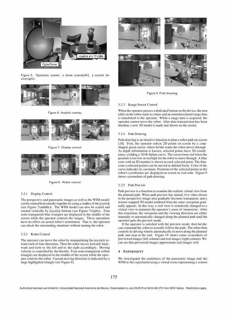
Figure 8: Robot control.
3.2.1 Display Control
The perspective and panoramic images as well as the WIM modelcan be rotated horizontally together by using a rudder of the joystick (see Figure 7(middle)). The WIM model can also be scaled androtated vertically by joystick buttons (see Figure 7(right)). Foursemi-transparent blue triangles are displayed in the middle of thescreen while the operator controls the images. These operationshave no effect on actual robot’s orientation. That is, the operator
can check the surrounding situations without turning the robot.
3.2.2 Robot Control
The operator can move the robot by manipulating the joystick to-ward each of four directions. Then the robot moves forward, back-ward and turns to the left and to the right accordingly. Movingvelocity is controlled by the throttle. Four semi-transparent yellowtriangles are displayed in the middle of the screen while the oper-ator controls the robot. Current moving direction is indicated by alarge highlighted triangle (see Figure 8).
Figure 9: Path drawing.
3.2.3 Range Sensor Control
When the operator presses a dedicated button on the device, the turntable on the robot starts to rotate and an omnidirectional range datais transferred to the operator. While a range data is acquired, theoperator cannot move the robot. After data transmission has beenfinished, a new 3D model is made and shown on the screen.
3.2.4 Path Drawing
Path drawing is an intuitive function to plan a robot path on screen[10]. First, the operator selects 2D points on screen by a cone-shaped, green cursor, where he/she wants the robot moves through.As depth information is known, selected points have 3D coordi-nates, yielding a 3D B-Spline curve. The cursor turns red when theposition is too low or too high for the robot to move through. A bluecone with an ID number is shown at each selected point. The bluecones (selected points) can be moved or deleted freely. Color of the
curve indicates its curvature. Positions of the selected points in therobot’s coordinates are displayed on screen in real-time. Figure 9shows screenshots of path drawing.
3.2.5 Path Preview
Path preview is a function to examine the realistic virtual view fromthe planned path. When path preview has started, live video shownin the perspective image area gradually becomes transparent, and atexture-mapped 3D model rendered from the same viewpoint grad-ually appears. In this way, a real view is seamlessly changed to avirtual view to maintain the operator’s sense of immersion. Afterthis transition, the viewpoint and the viewing direction are eithermanually or automatically changed along the planned path until theoperator quits the preview mode.
If the operator is satisfied with the preview result, then he/shecan command the robot to actually follow the path. The robot thencontrols its driving wheels automatically to move along the plannedpath and stop at the end. Figure 10 shows some screenshots of previewed images (left column) and real images (right column). Wecan see that previewed images approximate real images well.
4 EXPERIMENT
We investigated the usefulness of the panoramic image and theWIM in the experiment using a virtual scene representing a remote
Authorized licensed use limited to: Universidad Nacional Autonoma de Mexico. Downloaded on July 28,2010 at 04:03:48 UTC from IEEE Xplore. Restrictions apply.

8/12/2019 A 2D-3D Integrated Interface for Mobile Robot Control Using Omnidirectional Images and 3D Geometric Models
http://slidepdf.com/reader/full/a-2d-3d-integrated-interface-for-mobile-robot-control-using-omnidirectional 4/4
176
Figure 10: Preview (left column )and real view (right coloumn).
environment. In this experiment, nine subjects in their early twen-ties took part in two tasks with four visualization conditions. Thefirst task (operation task) is to move the robot from a start point toa goal as fast as possible. The second task (search task) is to col-lect items in the environment as many as possible in a limited time.Four conditions consist of combinations of with and without thepanoramic image and the WIM. Each of the subjects performed thetwo tasks with four conditions (totally eight trials) in a randomizedorder. After the experiment, subjects were asked to evaluate oper-ability and searchability of each visualization condition in a scaleof 1 (worst) to 5 (best).
Figure 11 shows average scores of the questionnaire. It wasconfirmed through a one-way ANOVA that the panoramic imageimproved searchability but not operability. In the operation task,rear and side images were rarely used because forward moving was
mostly sufficient to complete the task. In the search task, on theother hand, rear and side information was highly necessary for ef-ficient searching and for backward moving from a dead end. As adrawback of the panoramic image, however, some subjects felt itdifficult to estimate the distance to obstacles in rear and side direc-tions. It was also confirmed through a one-way ANOVA that theWIM improved both operability and searchability. It was clear thatthe 3D map was useful in both tasks to grasp the robot position,distance to obstacles, and the robot’s progress through the environ-ment. Experimental results show that our visualization technique ismore useful than traditional visualization techniques with forward
Figure 11: Subjective evaluation.
images only in both robot operation and information gathering.
5 CONCLUSION
In this paper, we have proposed a 2D-3D integrated interface formobile robot control. Omnidirectional images provide real-time vi-sual information at the remote environment, while a miniaturized3D geometric model intuitively shows the robot’s position and ori-
entation, and 3D structure of the remote environment. With depthinformation of the remote environment, a variety of 3D visualiza-tion and interaction techniques are available on 2D live video im-age in a manner of omnidirectional video see-through AR. Futurework includes improvement of 3D model quality and rigorous userstudies to validate the effectiveness of the proposed remote control
system.
REFERENCES
[1] H. Nagahara, Y. Yagi, and M. Yachida. Super Wide View Tele-
operation System. In Proc. IEEE Int. Conf. Multisensor Fusion and
Integration for Intelligent Systems (MFI2003), pp.149–154, 2003.
[2] H. K. Keskinpala, J. A. Adams, and K. Kawamura. Pda-Based
Human-Robotic Interface. In Proc. IEEE Conf. on SMC , 2003.
[3] M. Sugimoto, G. Kagotani, H. Nii, N. Shiroma, M. Inami, and F. Mat-suno. Time Follower’s Vision: A Teleoperation Interface with Past
Images. In IEEE CG&A, Vol.25, No.1, pp.54–63, 2005.
[4] B. Ricks, C. W. Nielsen, and M. A. Goodrich. Ecological Displays
for Robot Interaction: A New Perspective. In Proc. IEEE/RSJ Inter-
national Conference on Intelligent Robots and Systems (IROS), 2004.
[5] P. Milgram and F. Kishino. A taxonomy of mixed reality visual
display. In IEICE Trans. on Information and Systems, E77-D(12),
pp.1321–1329, 1994.
[6] R. Stoakley, M. J. Conway, and R. Pausch. Virtual Reality on a WIM:
Interactive Worlds in Miniature. In Proc. of SIGCHI ’95, pp.265–272,
1995.
[7] K. Yamazawa, Y. Yagi, and M. Yachida. Omnidirectional Image Sen-
sor - Hyper Omni Vision -. In Proc. Int. Conf. on Automation Tech-
nology, 1994.
[8] P. J. Besl and N. D. McKay. A method for registration of 3-d shapes.
In IEEE Trans. PAMI , Vol.14, No.2, pp.239–256, 1992.
[9] N. Shibano, P. V. Hareesh, M. Kashiwagi, K. Sawada, and H. Take-
mura. Development of VR Experiencing System with Hemi-Spherical
Immersive Projection Display. In Proc. Int. Display Research
Conf./Int. Display Workshops (Asia Display/IDW), 2001.
[10] T. Igarashi, R. Kadobayashi, K. Mase, and H. Tanaka. Path Drawing
for 3D Walkthrough. In 11th Annual Symposium on User Interface
Software and Technology (UIST ’98), pp.173–174, 1998.
Authorized licensed use limited to: Universidad Nacional Autonoma de Mexico. Downloaded on July 28,2010 at 04:03:48 UTC from IEEE Xplore. Restrictions apply.
Recommended