1
CCP
Dept. of Orthodontics
CEPHALOMETRICS
Lateral cephalogram:- morphology- cephalometrics:
- diagnosis- growth analysis- treatment evaluation
2
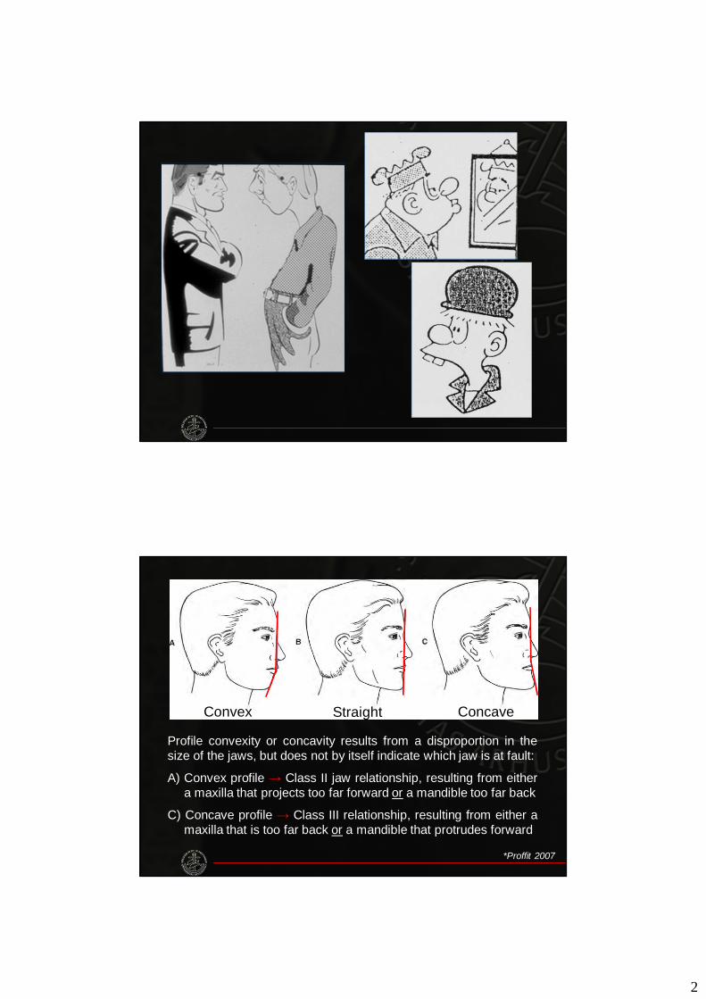
Convex Straight Concave
Profile convexity or concavity results from a disproportion in thesize of the jaws, but does not by itself indicate which jaw is at fault:
A) Convex profile → Class II jaw relationship, resulting from eithera maxilla that projects too far forward or a mandible too far back
C) Concave profile → Class III relationship, resulting from either amaxilla that is too far back or a mandible that protrudes forward
*Proffit 2007
3
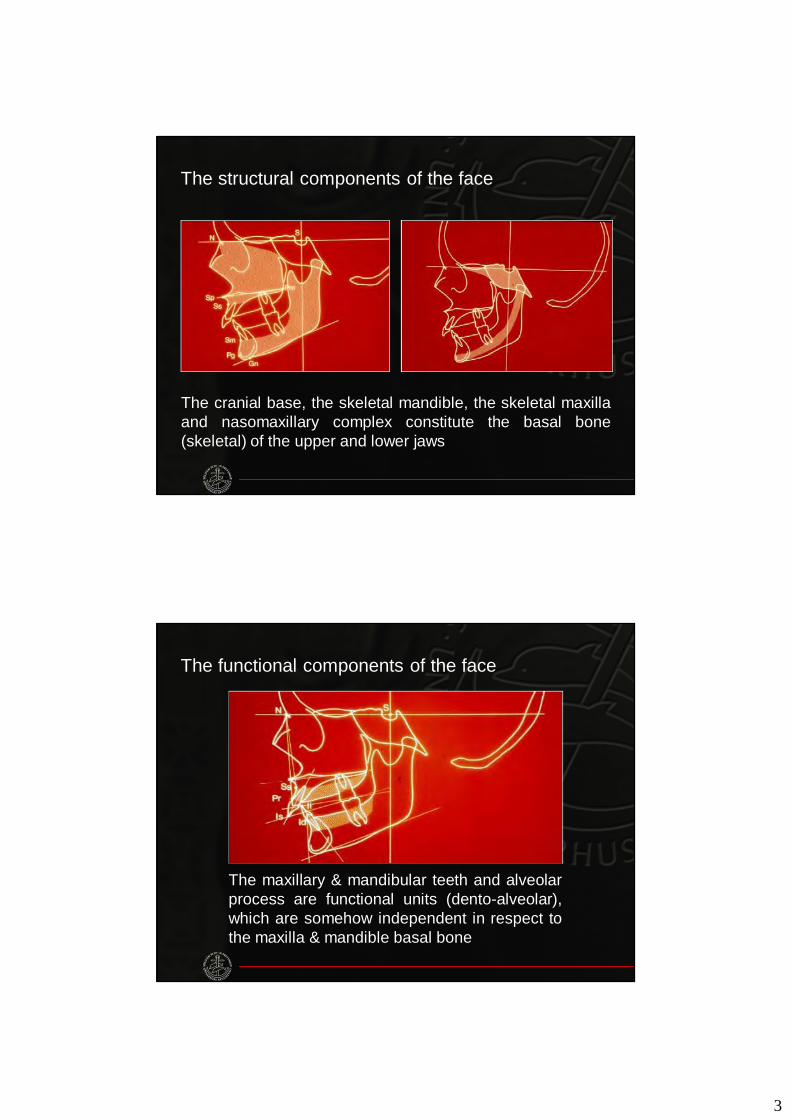
The cranial base, the skeletal mandible, the skeletal maxillaand nasomaxillary complex constitute the basal bone(skeletal) of the upper and lower jaws
The structural components of the face
The maxillary & mandibular teeth and alveolarprocess are functional units (dento-alveolar),which are somehow independent in respect tothe maxilla & mandible basal bone
The functional components of the face
4
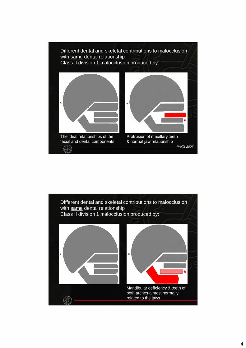
Different dental and skeletal contributions to malocclusion with same dental relationshipClass II division 1 malocclusion produced by:
*Proffit 2007
Protrusion of maxillary teeth& normal jaw relationship
The ideal relationships of the facial and dental components
*
Different dental and skeletal contributions to malocclusion with same dental relationshipClass II division 1 malocclusion produced by:
Mandibular deficiency & teeth of both arches almost normally related to the jaws
*
5
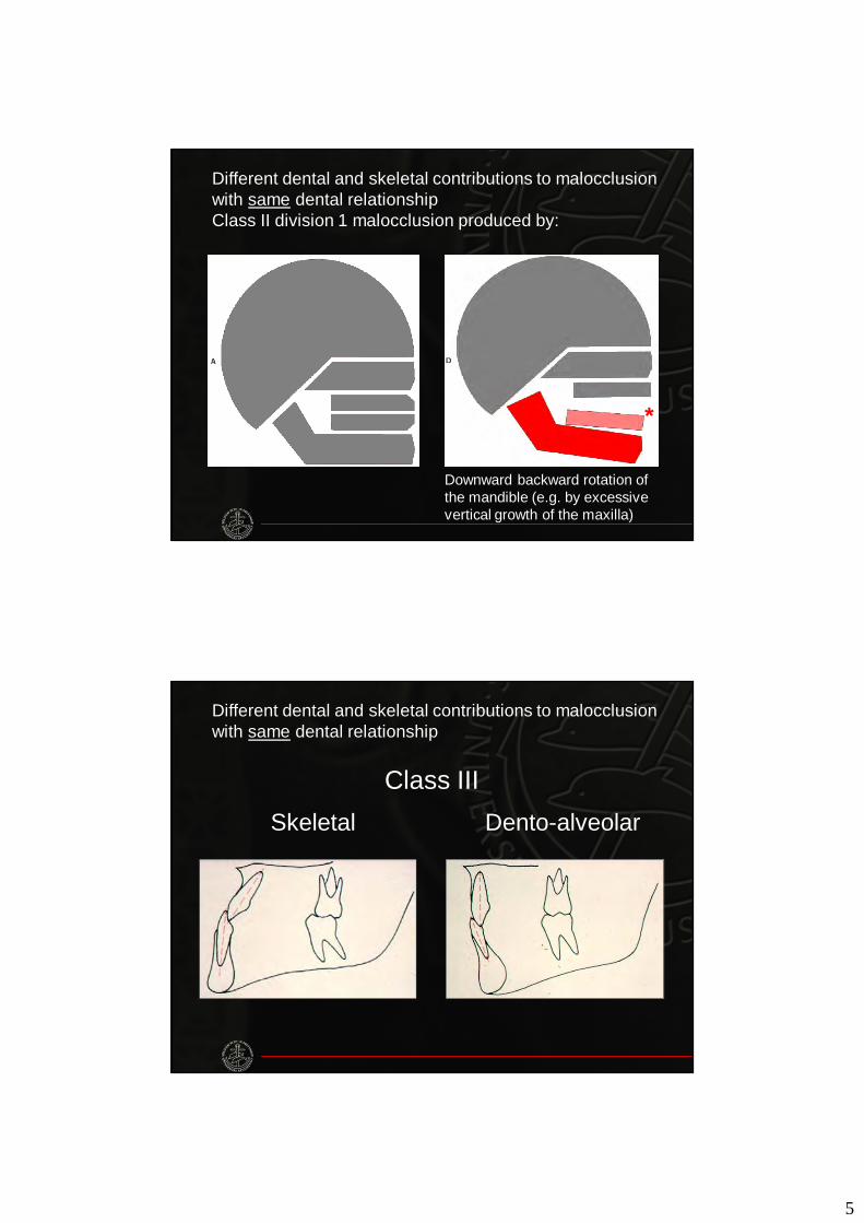
Different dental and skeletal contributions to malocclusion with same dental relationshipClass II division 1 malocclusion produced by:
Downward backward rotation of the mandible (e.g. by excessive vertical growth of the maxilla)
*
Dento-alveolarSkeletal
Class III
Different dental and skeletal contributions to malocclusion with same dental relationship
6
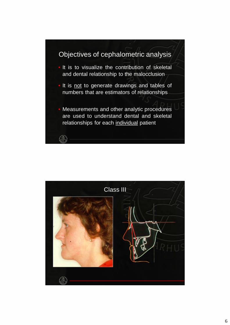
Objectives of cephalometric analysis
• It is to visualize the contribution of skeletaland dental relationship to the malocclusion
• It is not to generate drawings and tables ofnumbers that are estimators of relationships
• Measurements and other analytic proceduresare used to understand dental and skeletalrelationships for each individual patient
Class III
7
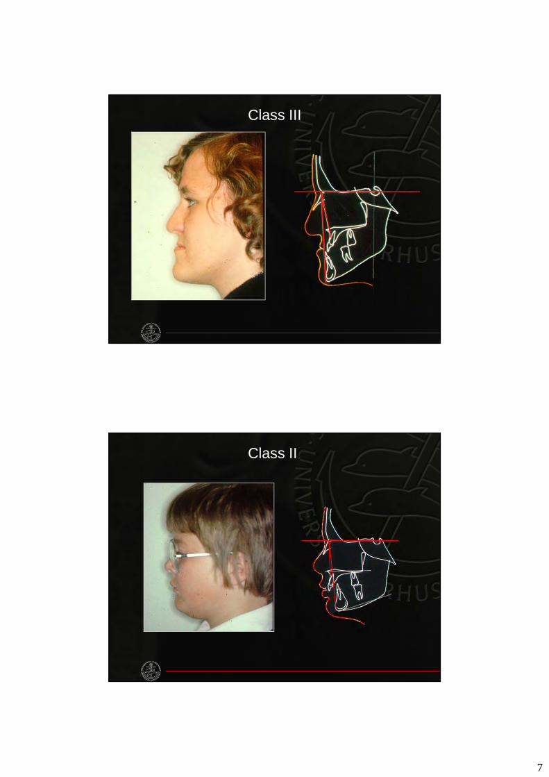
Class III
Class II
8
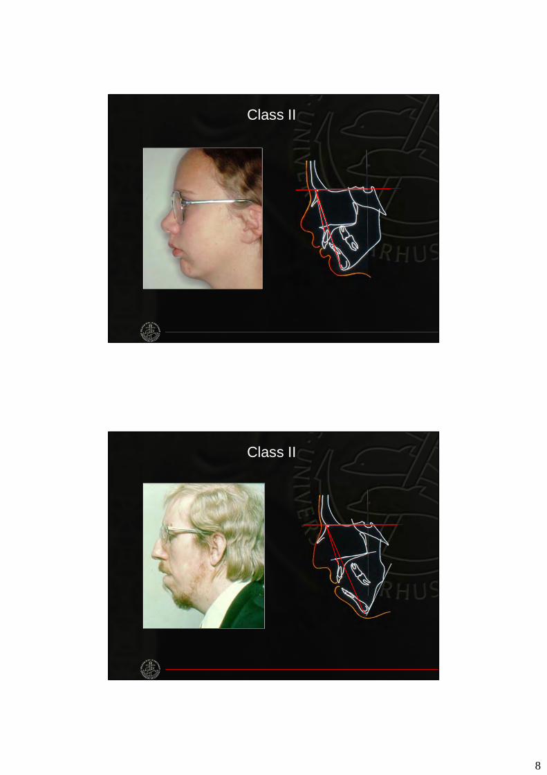
Class II
Class II
9
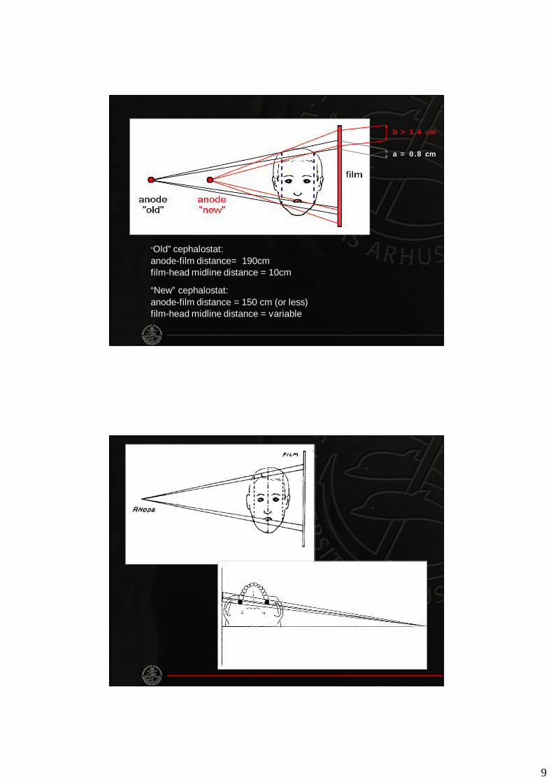
“Old” cephalostat:anode-film distance= 190cmfilm-head midline distance = 10cm
“New” cephalostat:anode-film distance = 150 cm (or less)film-head midline distance = variable
a = 0.8 cm
b > 1.4 cm
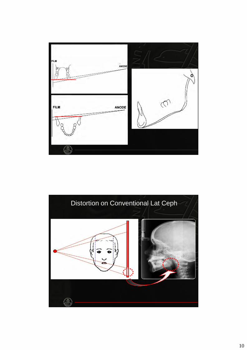
10
Distortion on Conventional Lat Ceph
11
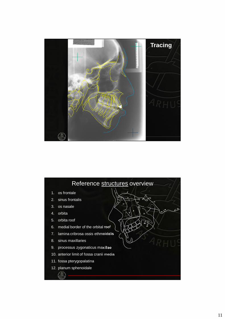
Tracing
1. os frontale
2. sinus frontalis
3. os nasale
4. orbita
5. orbita roof
6. medial border of the orbital roof
7. lamina cribrosa ossis ethmoidalis
8. sinus maxillaries
9. processus zygonaticus maxillae
10. anterior limit of fossa cranii media
11. fossa pterygopalatina
12. planum sphenoidale
Reference structures overview
12
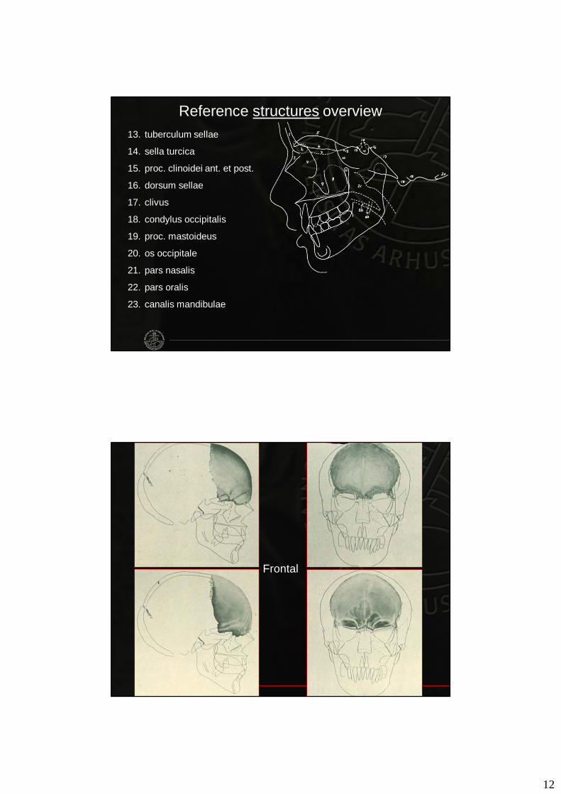
13. tuberculum sellae
14. sella turcica
15. proc. clinoidei ant. et post.
16. dorsum sellae
17. clivus
18. condylus occipitalis
19. proc. mastoideus
20. os occipitale
21. pars nasalis
22. pars oralis
23. canalis mandibulae
Reference structures overview
Frontal
13
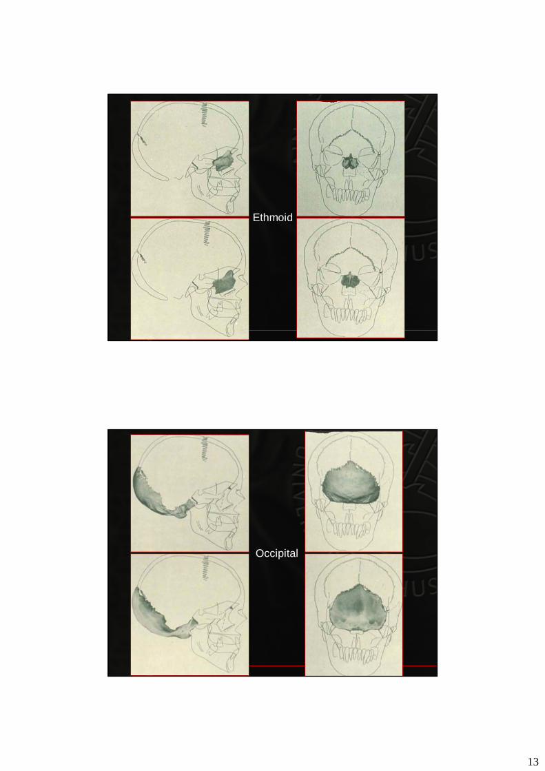
Ethmoid
Occipital
14
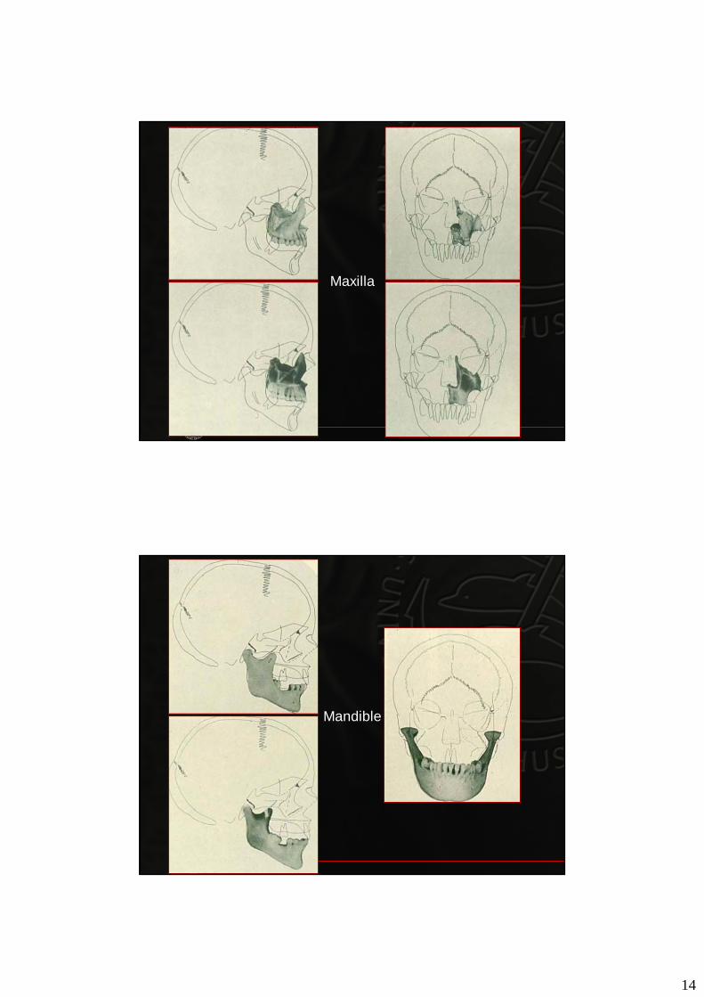
Maxilla
Mandible
15
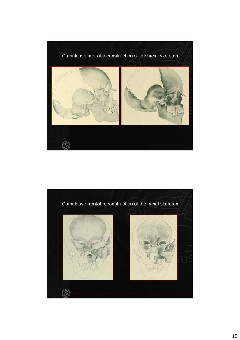
Cumulative lateral reconstruction of the facial skeleton
Cumulative frontal reconstruction of the facial skeleton
16
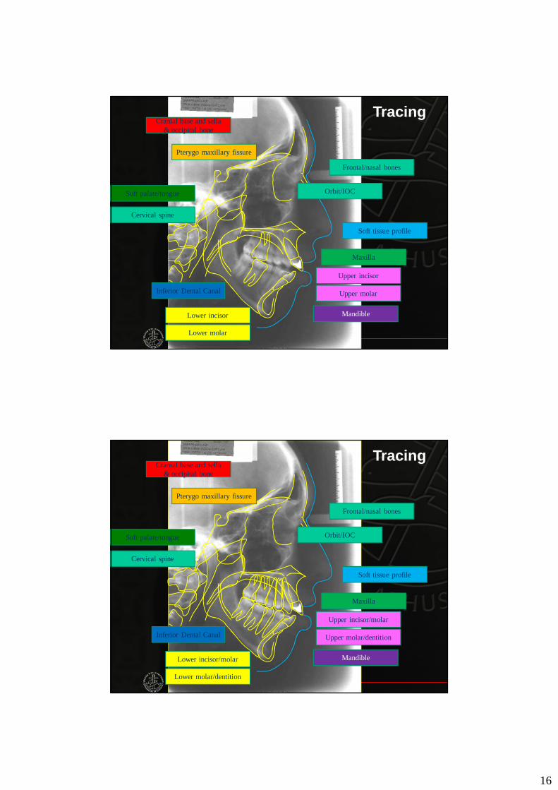
Soft palate/tongue
Soft tissue profile
Cranial base and sella& occipital bone
Maxilla
Mandible
Frontal/nasal bones
Upper incisor
Lower incisor
Orbit/IOC
Pterygo maxillary fissure
Cervical spine
Upper molar
Lower molar
Inferior Dental Canal
Tracing
Soft palate/tongue
Soft tissue profile
Cranial base and sella& occipital bone
Maxilla
Mandible
Frontal/nasal bones
Upper incisor/molar
Lower incisor/molar
Orbit/IOC
Pterygo maxillary fissure
Cervical spine
Upper molar/dentition
Lower molar/dentition
Inferior Dental Canal
Tracing
17
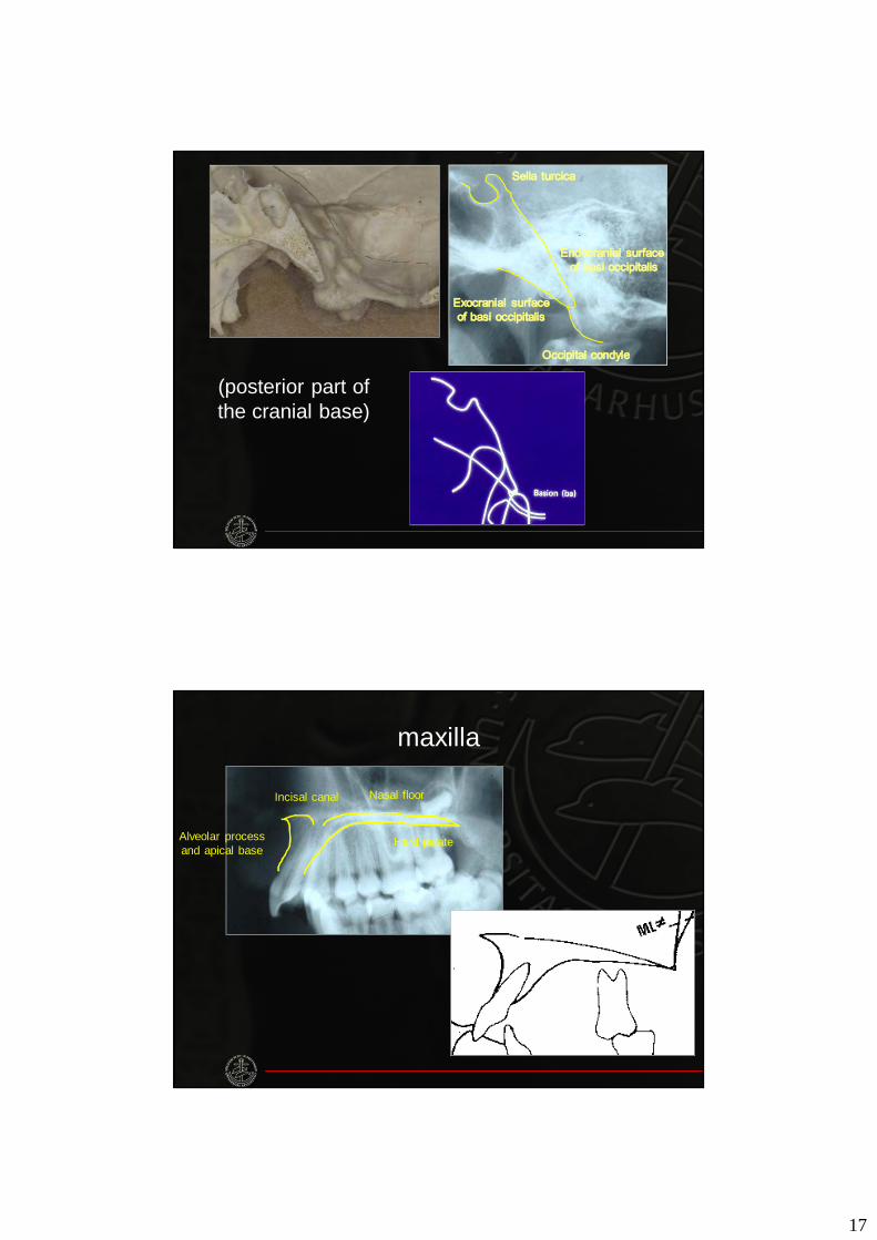
(posterior part of the cranial base)
Alveolar process and apical base
Hard palate
Nasal floorIncisal canal
maxilla
18
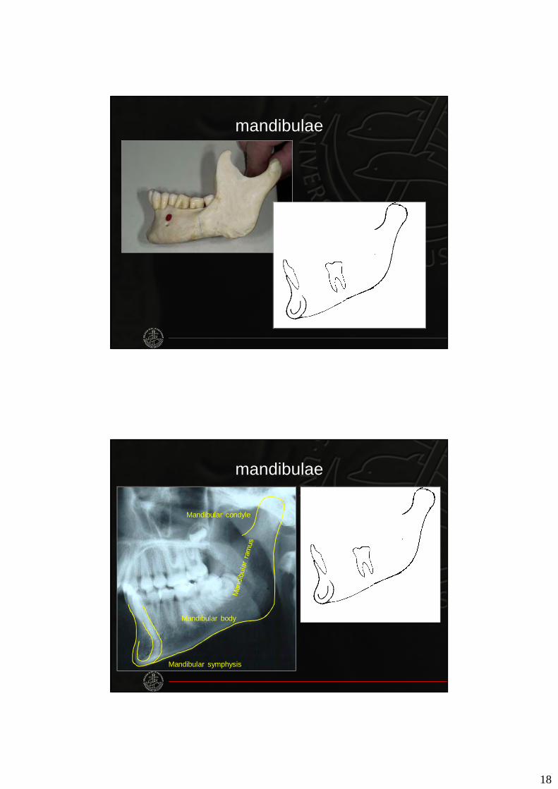
mandibulae
Mandibular symphysis
Mandibular body
Mandibular condyle
mandibulae
19
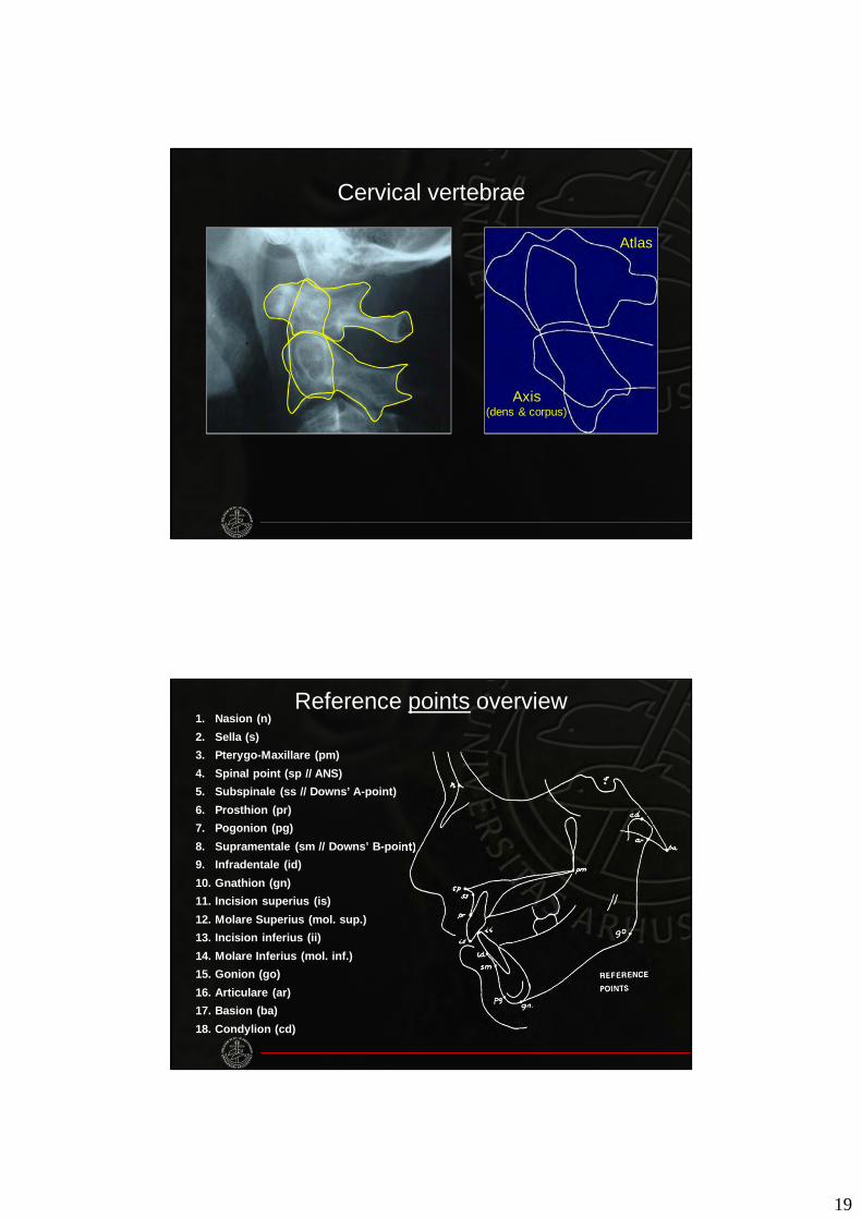
Cervical vertebrae
Axis(dens & corpus)
Atlas
Reference points overview1. Nasion (n)2. Sella (s)3. Pterygo-Maxillare (pm)4. Spinal point (sp // ANS)5. Subspinale (ss // Downs’ A-point)6. Prosthion (pr)7. Pogonion (pg)8. Supramentale (sm // Downs’ B-point)9. Infradentale (id)10. Gnathion (gn)11. Incision superius (is)12. Molare Superius (mol. sup.)13. Incision inferius (ii)14. Molare Inferius (mol. inf.)15. Gonion (go)16. Articulare (ar)17. Basion (ba)18. Condylion (cd)
20
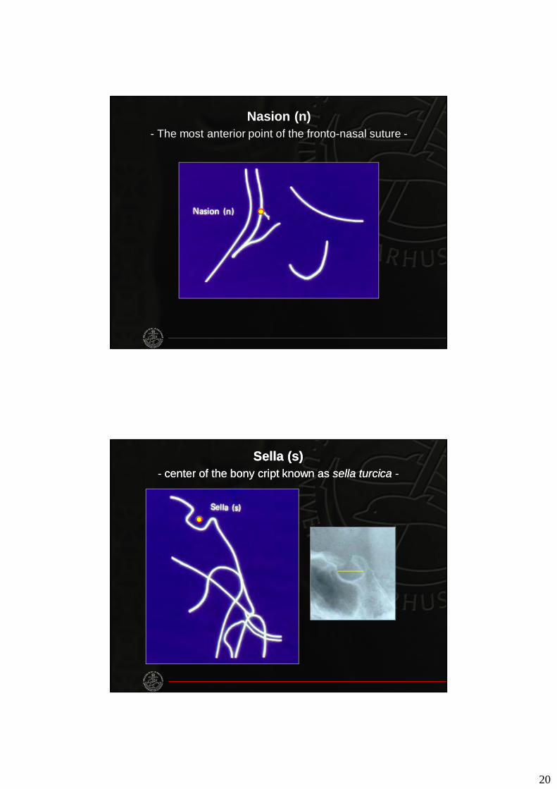
Nasion (n)- The most anterior point of the fronto-nasal suture -
Sella (s)- center of the bony cript known as sella turcica -
Sella (s)- center of the bony cript known as sella turcica -
21
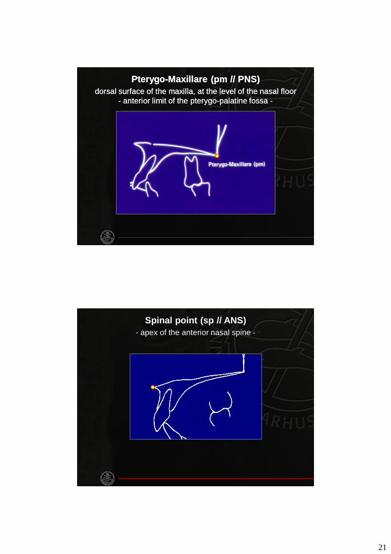
Pterygo-Maxillare (pm // PNS)dorsal surface of the maxilla, at the level of the nasal floor
- anterior limit of the pterygo-palatine fossa -
Pterygo-Maxillare (pm // PNS)dorsal surface of the maxilla, at the level of the nasal floor
- anterior limit of the pterygo-palatine fossa -
Spinal point (sp // ANS)- apex of the anterior nasal spine -
22
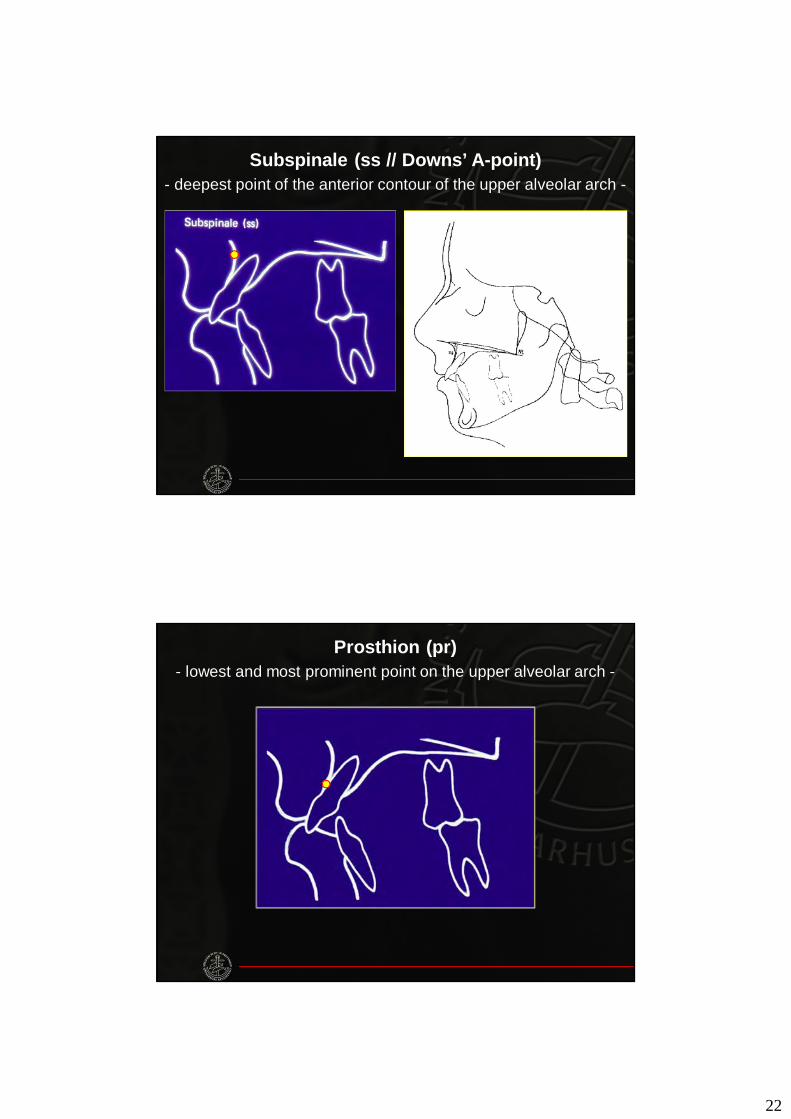
Subspinale (ss // Downs’ A-point)- deepest point of the anterior contour of the upper alveolar arch -
Prosthion (pr)- lowest and most prominent point on the upper alveolar arch -
23
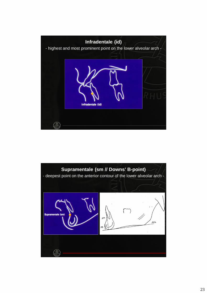
Infradentale (id)- highest and most prominent point on the lower alveolar arch -
Supramentale (sm // Downs’ B-point)- deepest point on the anterior contour of the lower alveolar arch -
24
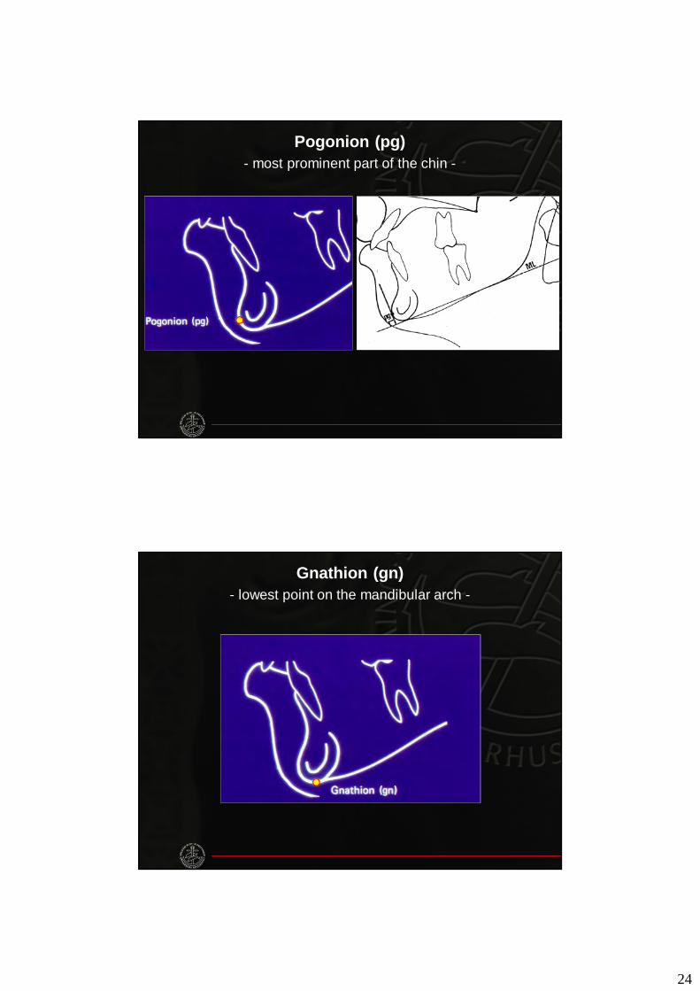
Pogonion (pg)- most prominent part of the chin -
Gnathion (gn)- lowest point on the mandibular arch -
25
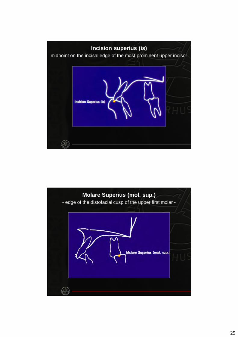
Incision superius (is)midpoint on the incisal edge of the most prominent upper incisor
Molare Superius (mol. sup.)- edge of the distofacial cusp of the upper first molar -
26
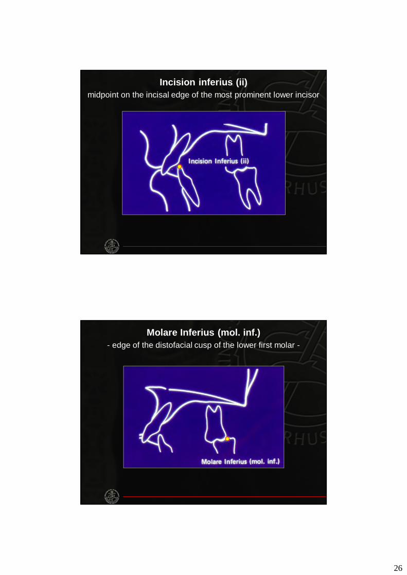
Incision inferius (ii)midpoint on the incisal edge of the most prominent lower incisor
Molare Inferius (mol. inf.)- edge of the distofacial cusp of the lower first molar -
27
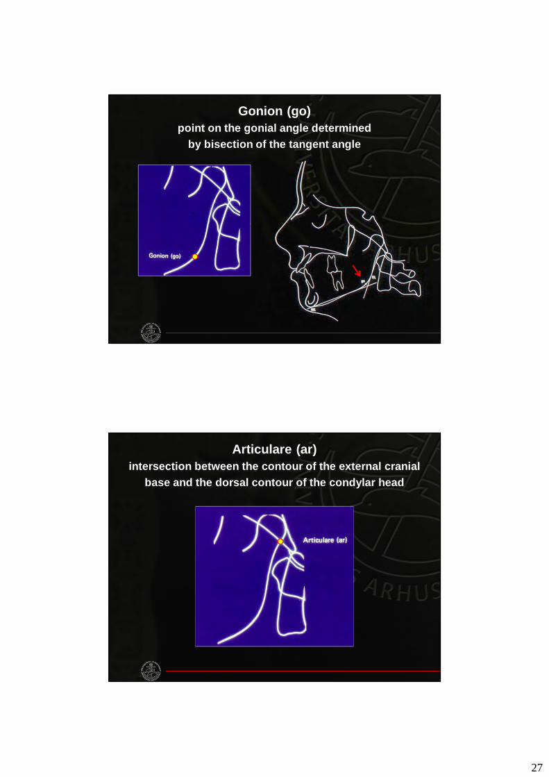
Gonion (go)point on the gonial angle determined
by bisection of the tangent angle
Articulare (ar)intersection between the contour of the external cranial
base and the dorsal contour of the condylar head
28
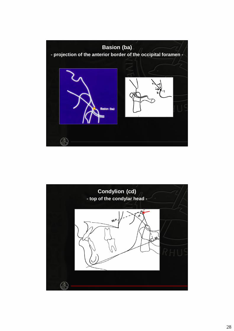
Basion (ba)- projection of the anterior border of the occipital foramen -
Condylion (cd)- top of the condylar head -
29
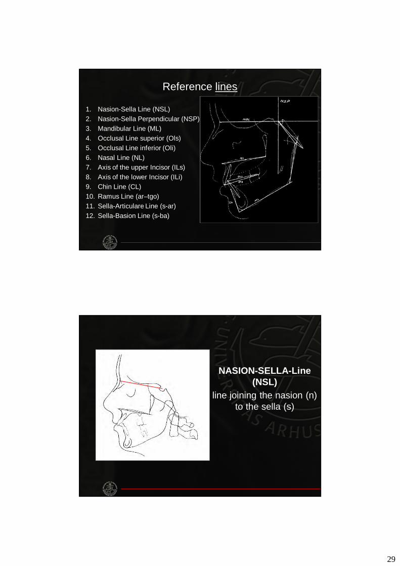
Reference lines
1. Nasion-Sella Line (NSL)2. Nasion-Sella Perpendicular (NSP)3. Mandibular Line (ML)4. Occlusal Line superior (Ols)5. Occlusal Line inferior (Oli)6. Nasal Line (NL)7. Axis of the upper Incisor (ILs)8. Axis of the lower Incisor (ILi)9. Chin Line (CL)10. Ramus Line (ar–tgo)11. Sella-Articulare Line (s-ar)12. Sella-Basion Line (s-ba)
NASION-SELLA-Line (NSL)
line joining the nasion (n) to the sella (s)
30
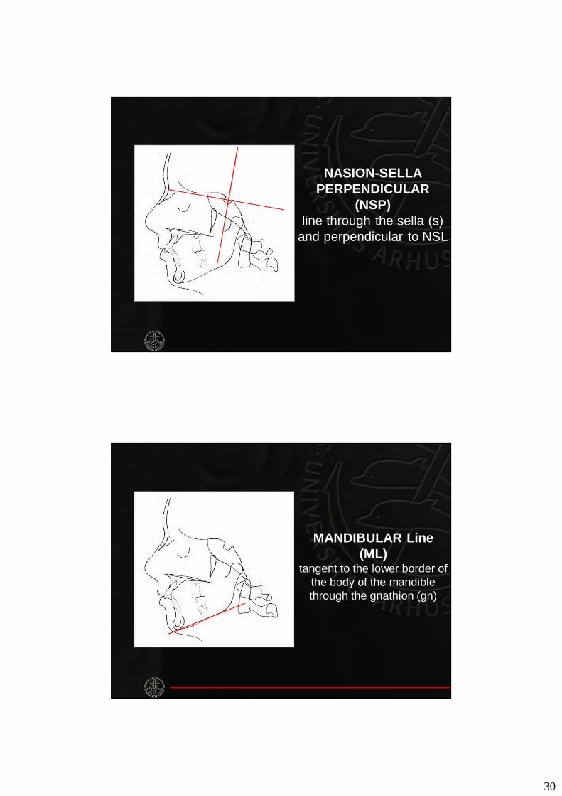
NASION-SELLA PERPENDICULAR
(NSP)line through the sella (s)
and perpendicular to NSL
MANDIBULAR Line(ML)
tangent to the lower border of the body of the mandible through the gnathion (gn)
31
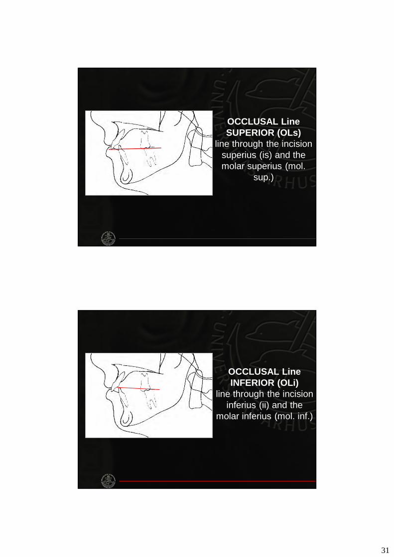
OCCLUSAL Line SUPERIOR (OLs)
line through the incisionsuperius (is) and the molar superius (mol.
sup.)
OCCLUSAL Line INFERIOR (OLi)
line through the incisioninferius (ii) and the
molar inferius (mol. inf.)

32
NASAL Line (NL)line through the spinal
point (sp) and the pterygomaxillare (pm)
AXIS of the UPPER INCISOR (ILs)
line connecting the incision superius (is)
to the apex of the upper incisor
33
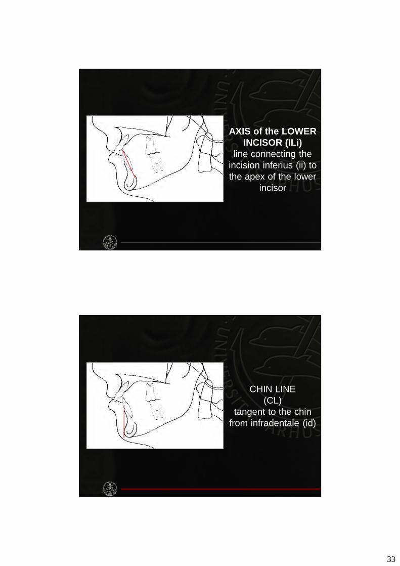
AXIS of the LOWER INCISOR (ILi)
line connecting the incision inferius (ii) to the apex of the lower
incisor
CHIN LINE(CL)
tangent to the chin from infradentale (id)
34
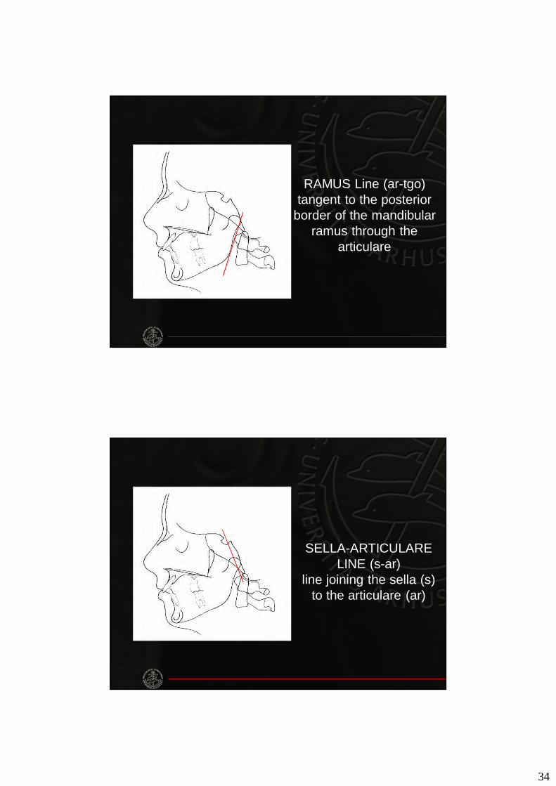
RAMUS Line (ar-tgo)tangent to the posterior
border of the mandibular ramus through the
articulare
SELLA-ARTICULARE LINE (s-ar)
line joining the sella (s)to the articulare (ar)
35
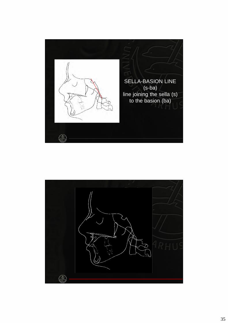
SELLA-BASION LINE(s-ba)
line joining the sella (s) to the basion (ba)
36
Dept. of Orthodontics
CEPHALOMETRICS- Part II -
37
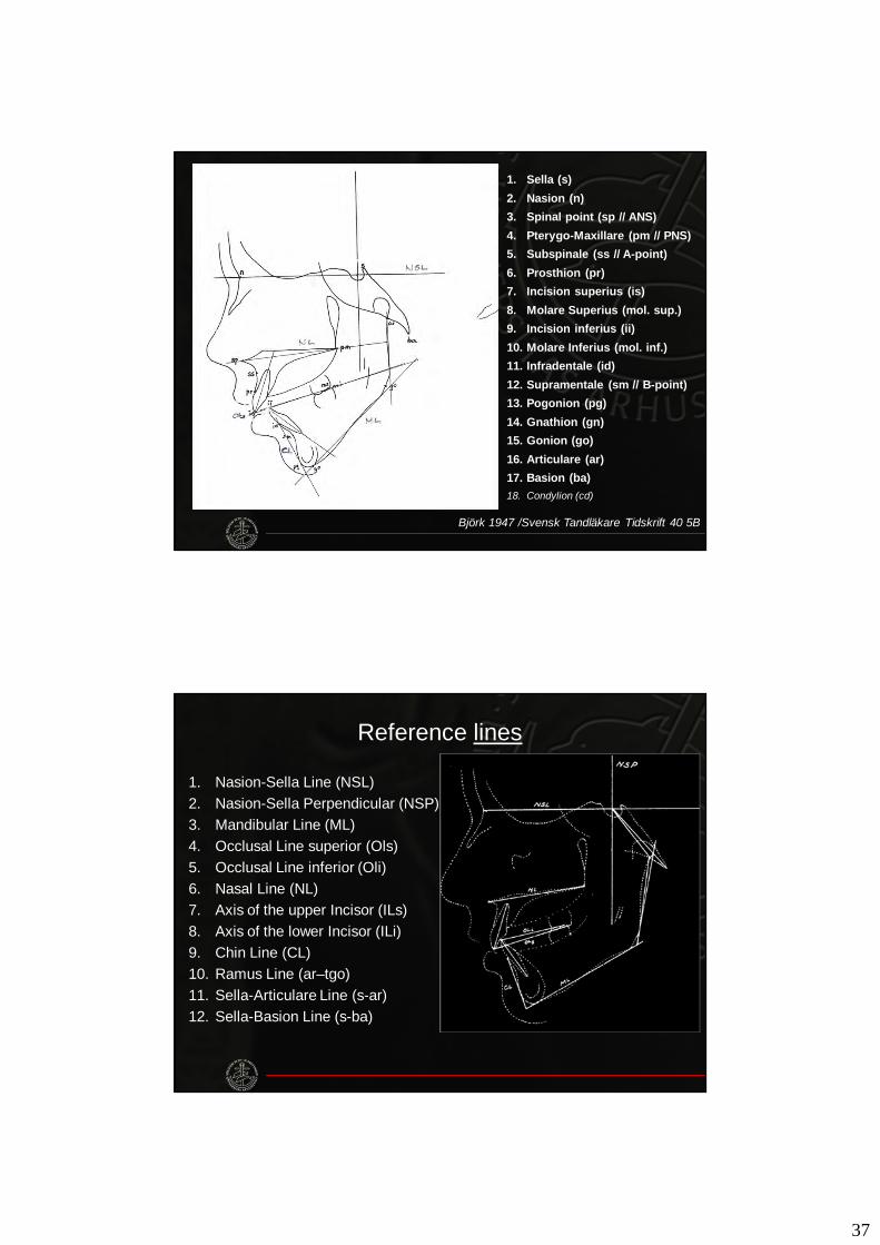
1. Sella (s)2. Nasion (n)3. Spinal point (sp // ANS) 4. Pterygo-Maxillare (pm // PNS)5. Subspinale (ss // A-point)6. Prosthion (pr)7. Incision superius (is)8. Molare Superius (mol. sup.)9. Incision inferius (ii)10. Molare Inferius (mol. inf.)11. Infradentale (id)12. Supramentale (sm // B-point)13. Pogonion (pg)14. Gnathion (gn)15. Gonion (go)16. Articulare (ar)17. Basion (ba)18. Condylion (cd)
Björk 1947 /Svensk Tandläkare Tidskrift 40 5B
Reference lines
1. Nasion-Sella Line (NSL)2. Nasion-Sella Perpendicular (NSP)3. Mandibular Line (ML)4. Occlusal Line superior (Ols)5. Occlusal Line inferior (Oli)6. Nasal Line (NL)7. Axis of the upper Incisor (ILs)8. Axis of the lower Incisor (ILi)9. Chin Line (CL)10. Ramus Line (ar–tgo)11. Sella-Articulare Line (s-ar)12. Sella-Basion Line (s-ba)
38
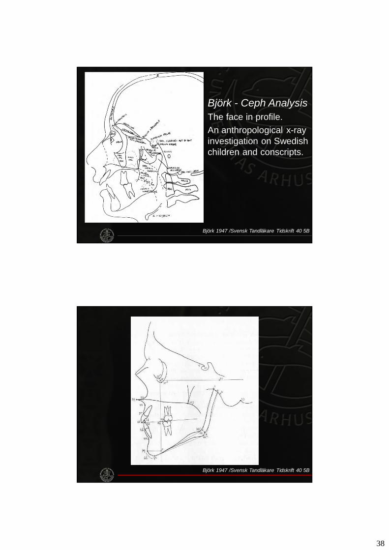
Björk - Ceph AnalysisThe face in profile.An anthropological x-ray investigation on Swedish children and conscripts.
Björk 1947 /Svensk Tandläkare Tidskrift 40 5B
Björk 1947 /Svensk Tandläkare Tidskrift 40 5B
39
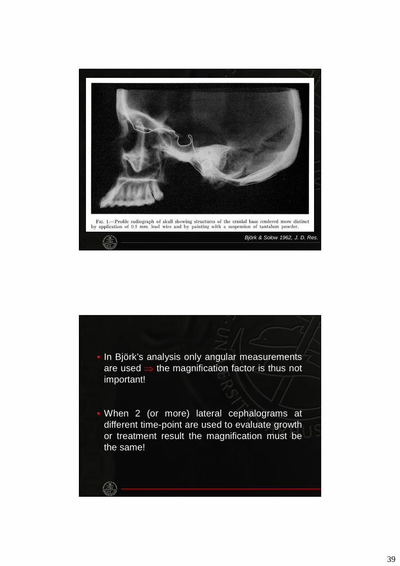
Björk & Solow 1962, J. D. Res.
• In Björk’s analysis only angular measurementsare used ⇒ the magnification factor is thus notimportant!
• When 2 (or more) lateral cephalograms atdifferent time-point are used to evaluate growthor treatment result the magnification must bethe same!
40
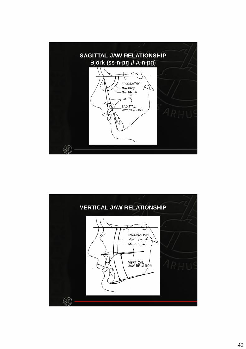
SAGITTAL JAW RELATIONSHIPBjörk (ss-n-pg // A-n-pg)
VERTICAL JAW RELATIONSHIP
41
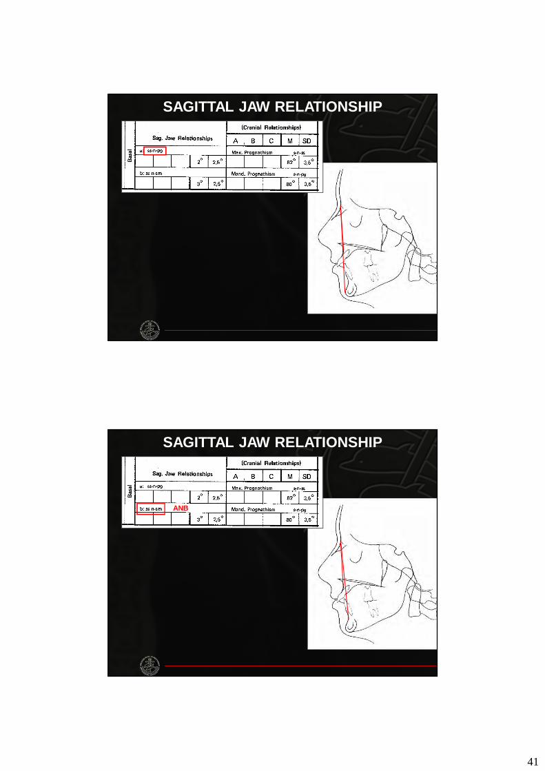
SAGITTAL JAW RELATIONSHIP
SAGITTAL JAW RELATIONSHIP
ANB
42
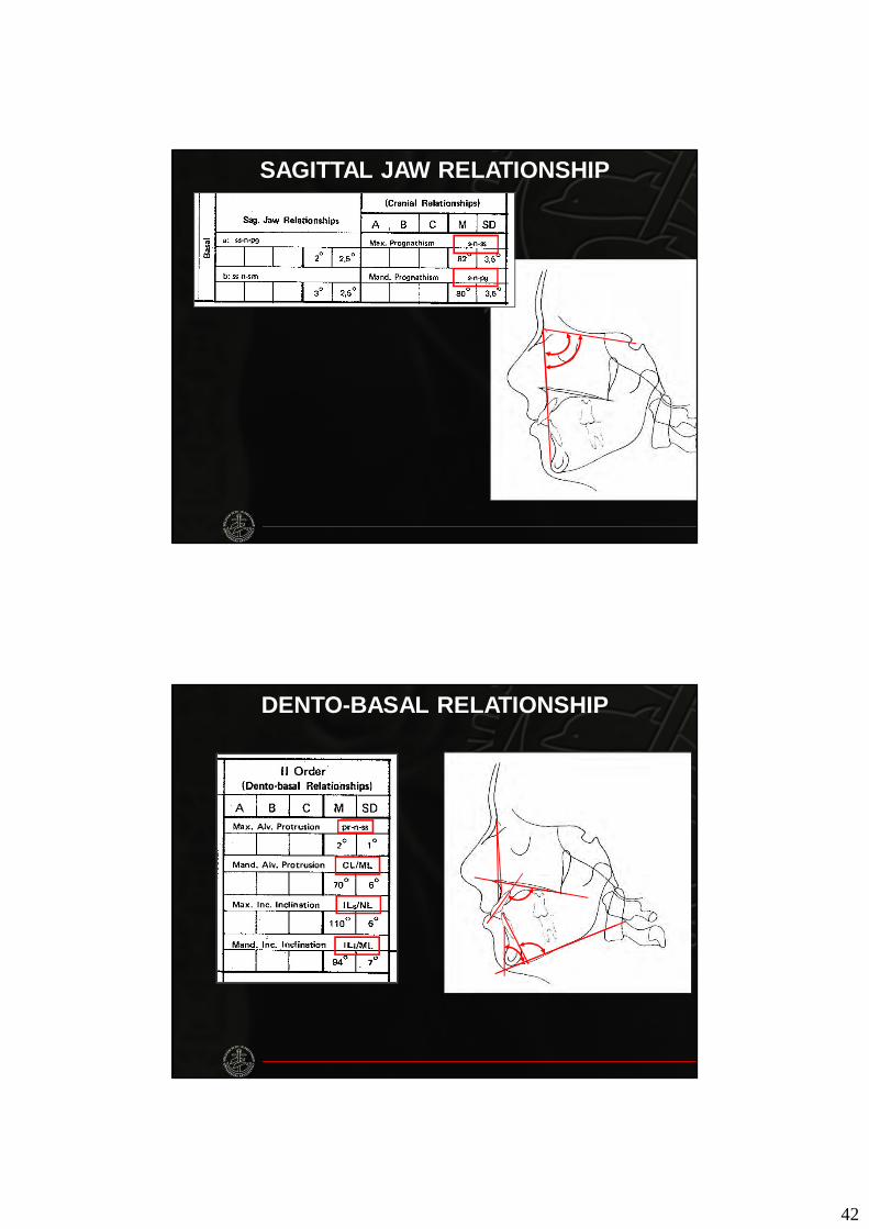
SAGITTAL JAW RELATIONSHIP
DENTO-BASAL RELATIONSHIP
43
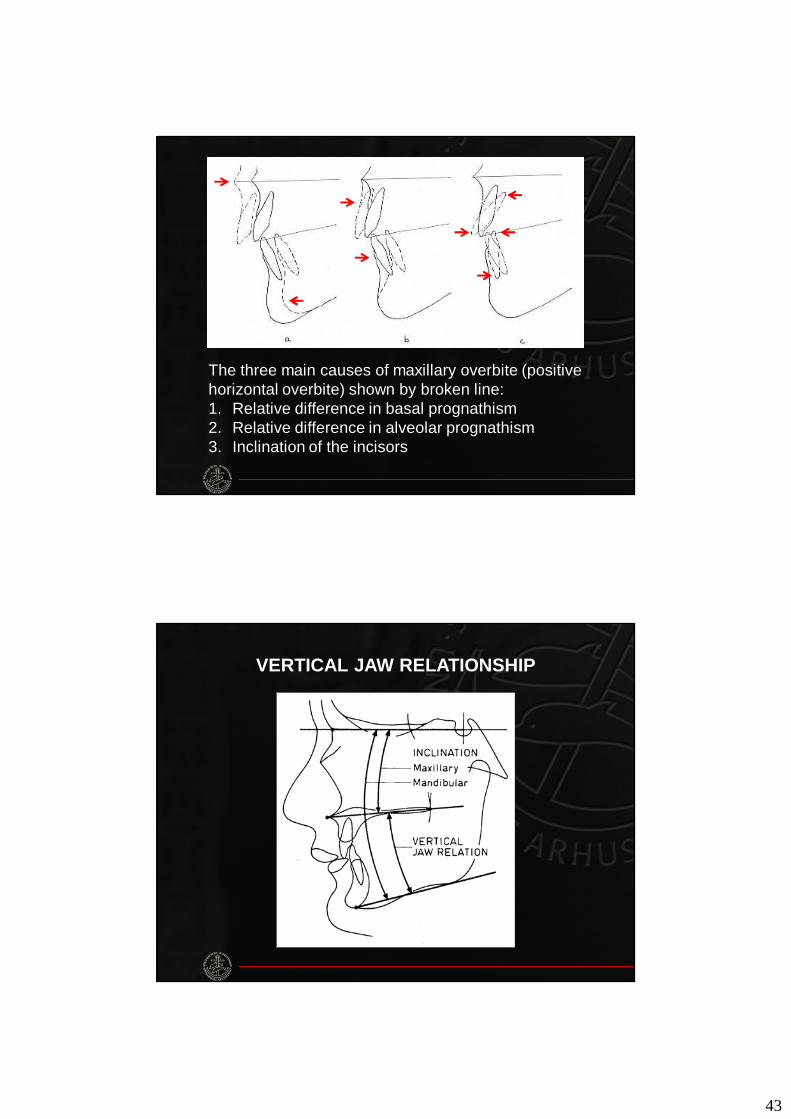
The three main causes of maxillary overbite (positive horizontal overbite) shown by broken line:1. Relative difference in basal prognathism2. Relative difference in alveolar prognathism3. Inclination of the incisors
VERTICAL JAW RELATIONSHIP
44
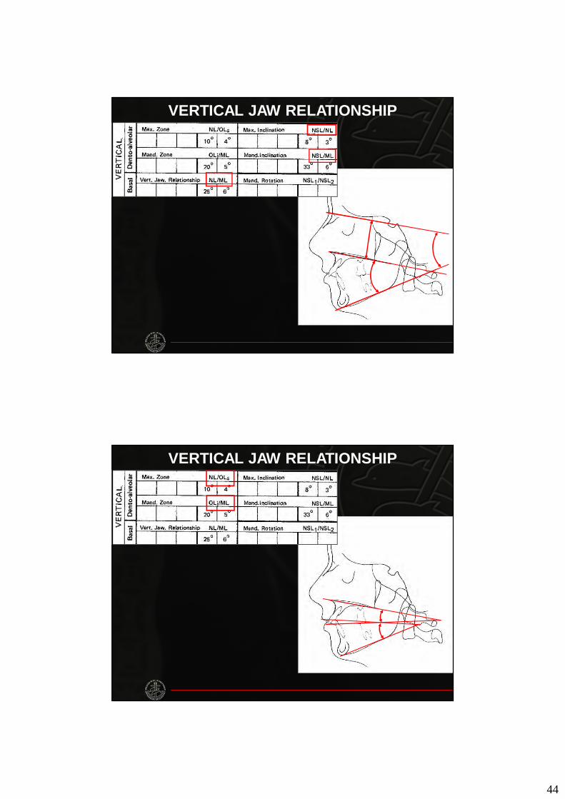
VERTICAL JAW RELATIONSHIP
VERTICAL JAW RELATIONSHIP
45
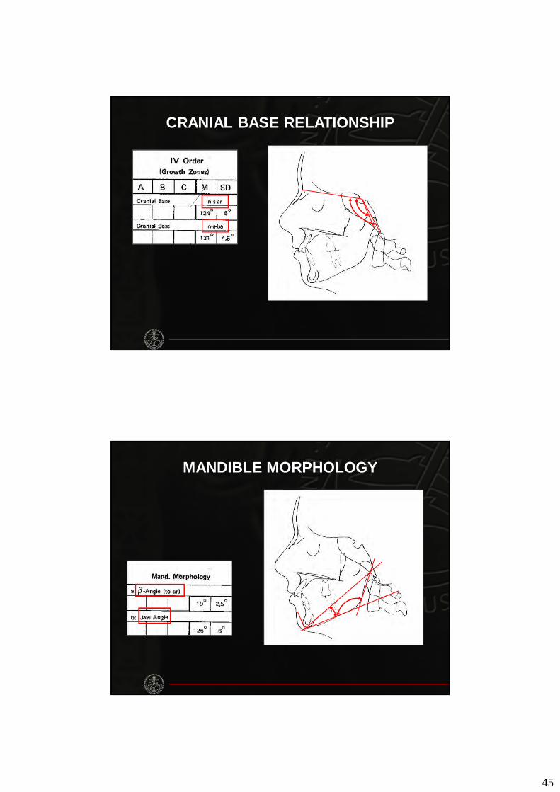
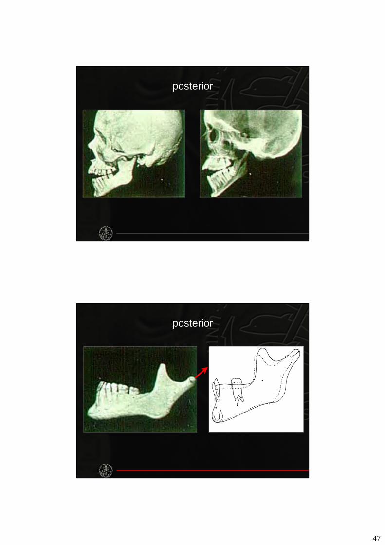
CRANIAL BASE RELATIONSHIP
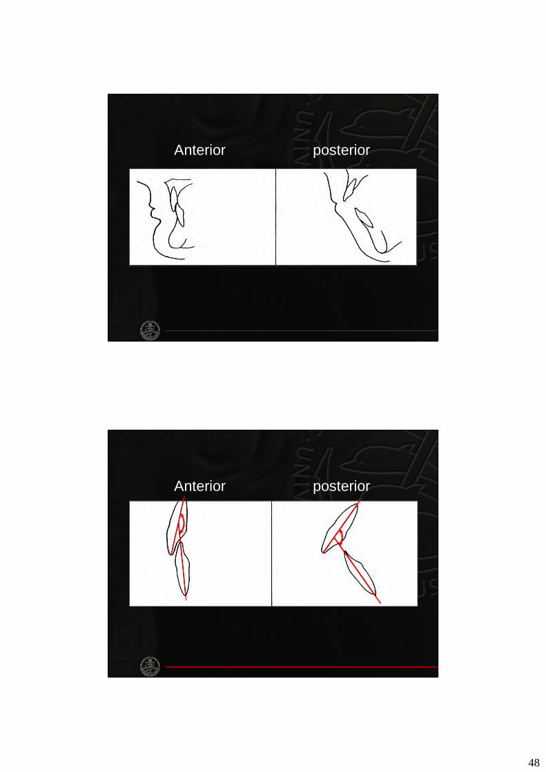
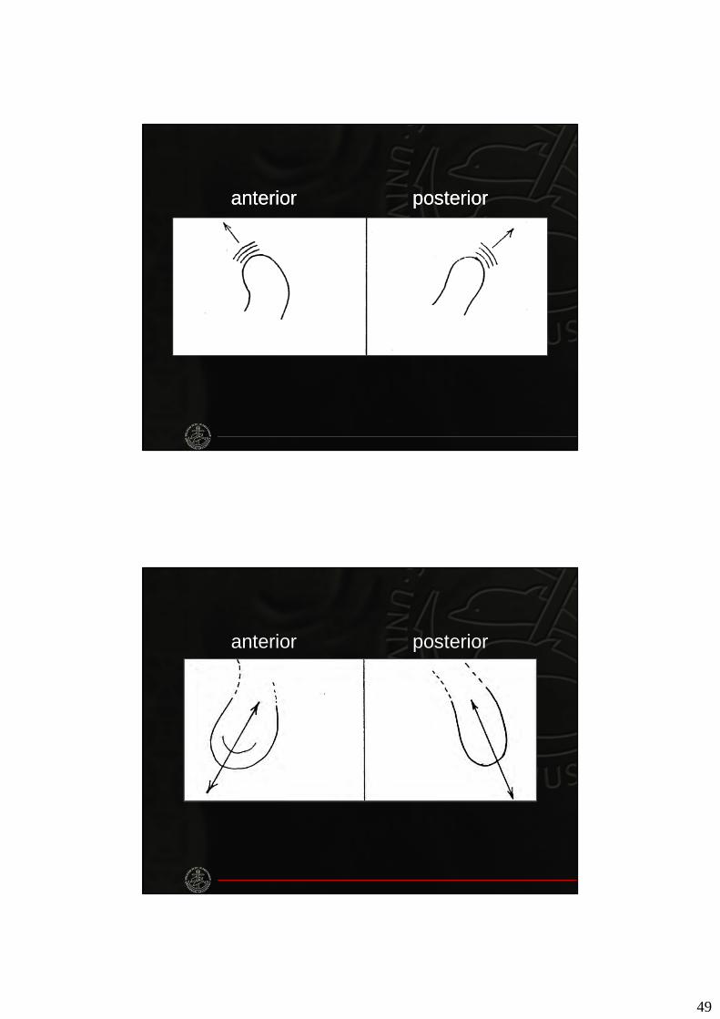
MANDIBLE MORPHOLOGY
46
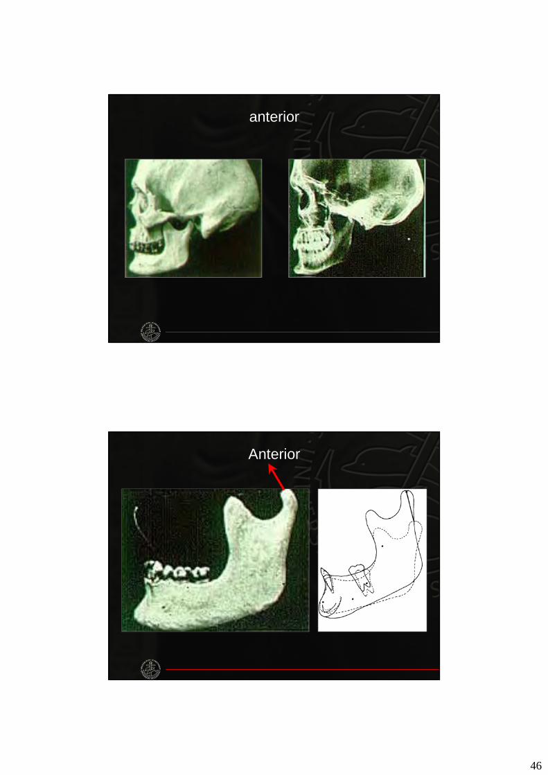
anterior
Anterior
47
posterior
posterior
48
Anterior posterior
Anterior posterior
49
anterioranterior posteriorposterior
anterior posterior

50
diminished n-s-ar diminished jaw angle
BJØRK ANALYSIS
• Column M: gives the mean value, inwhole degrees, taken from Björk’sinvestigations.
Standard deviation (σ):
• Results in the range ± 1σ include68% of the individuals in a normalpopulation.
• Results ranging from M-2σ up toM+2σ include 95% of the population.
• Results of the order M±3σ willinclude 99.7% of the population.
51
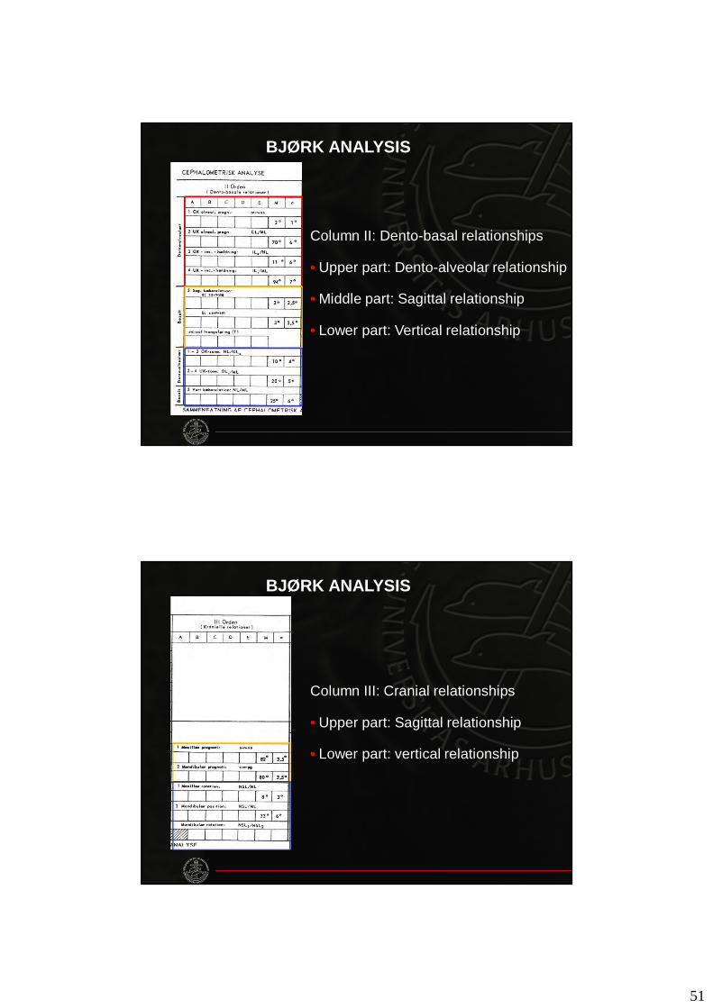
BJØRK ANALYSIS
Column II: Dento-basal relationships
• Upper part: Dento-alveolar relationship
• Middle part: Sagittal relationship
• Lower part: Vertical relationship
BJØRK ANALYSIS
Column III: Cranial relationships
• Upper part: Sagittal relationship
• Lower part: vertical relationship
52
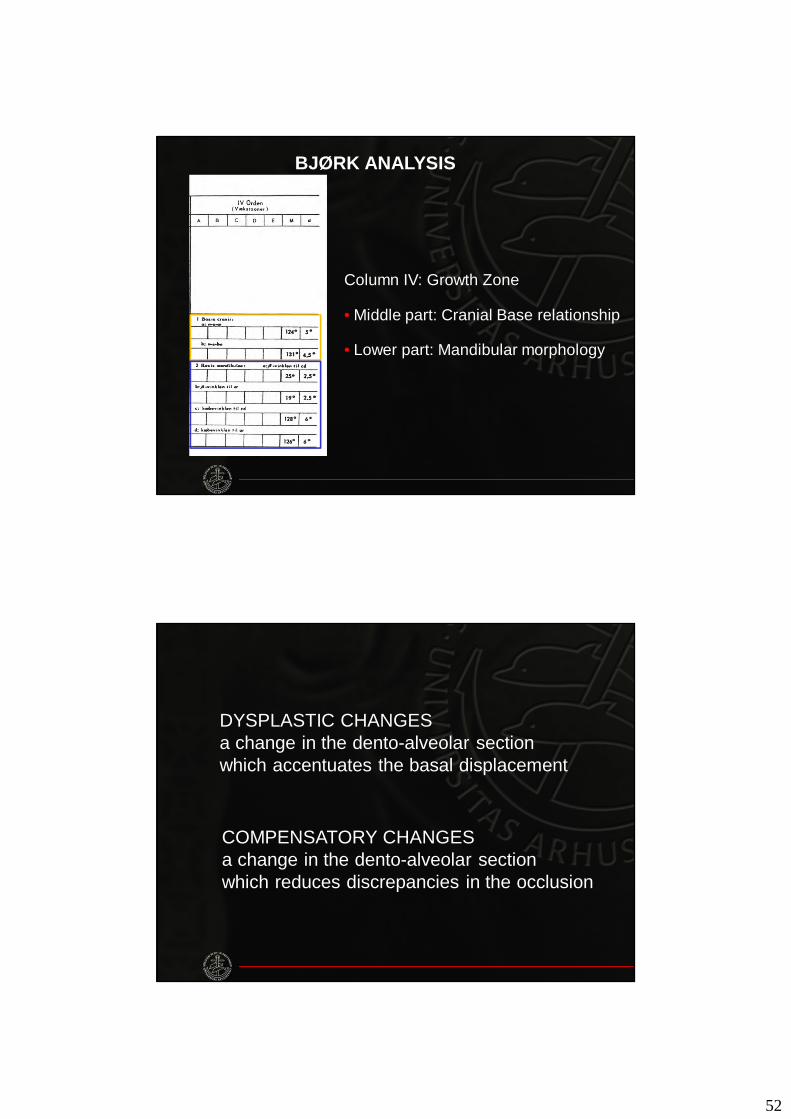
BJØRK ANALYSIS
Column IV: Growth Zone
• Middle part: Cranial Base relationship
• Lower part: Mandibular morphology
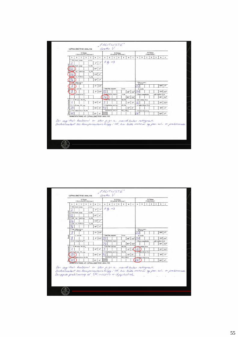
DYSPLASTIC CHANGESa change in the dento-alveolar sectionwhich accentuates the basal displacement
COMPENSATORY CHANGESa change in the dento-alveolar sectionwhich reduces discrepancies in the occlusion
53
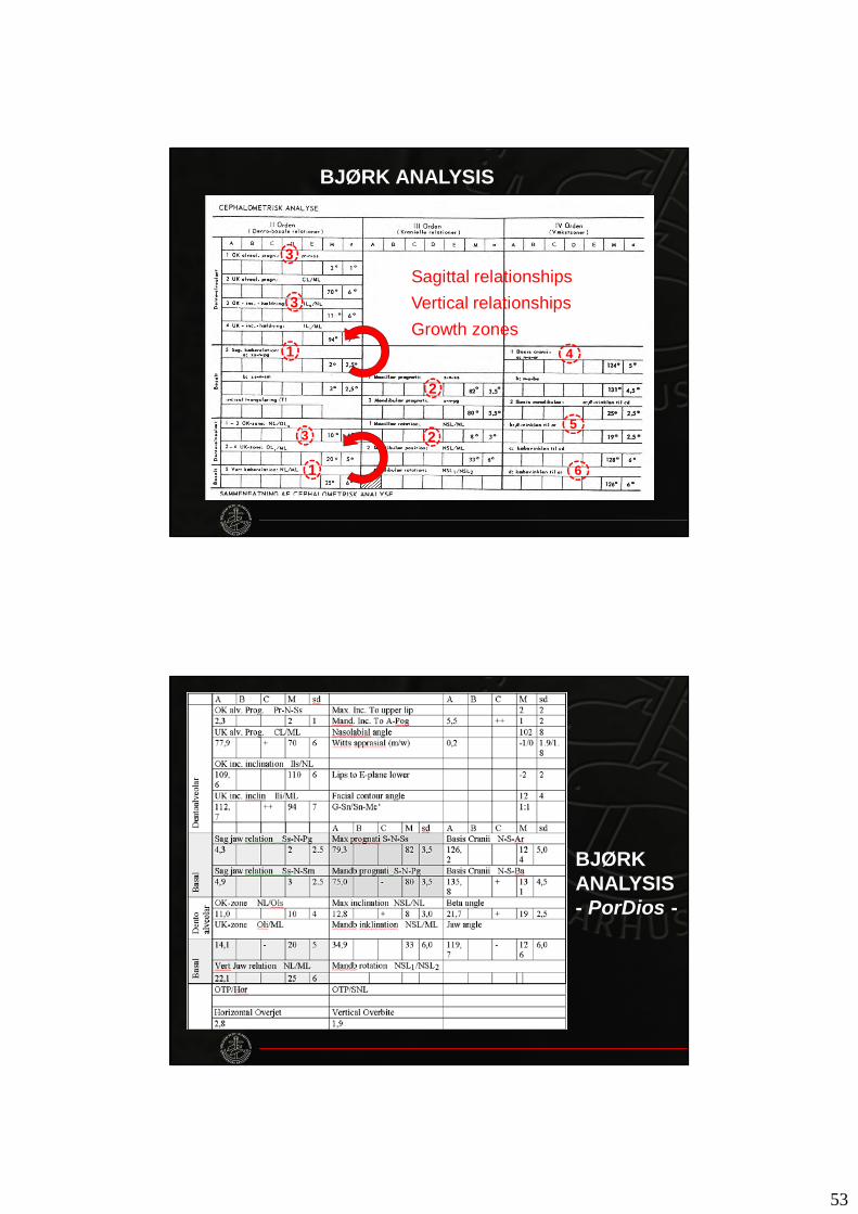
BJØRK ANALYSIS
1
2
3
1
23
4
5
6
3Sagittal relationshipsVertical relationshipsGrowth zones
BJØRKANALYSIS- PorDios -
54
55
Recommended