1
Assign a static IP address 192.168.1.100 for your computer. Please refer tothe T3 in Troubleshooting guide if you need assistance.
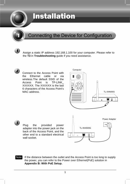
Connect to the Access Point with the Ethernet cable or via wireless.The default SSID of the Access Point is TP-LINK_XXXXXX. The XXXXXX is the last 6 characters of the Access Point’s MAC address.
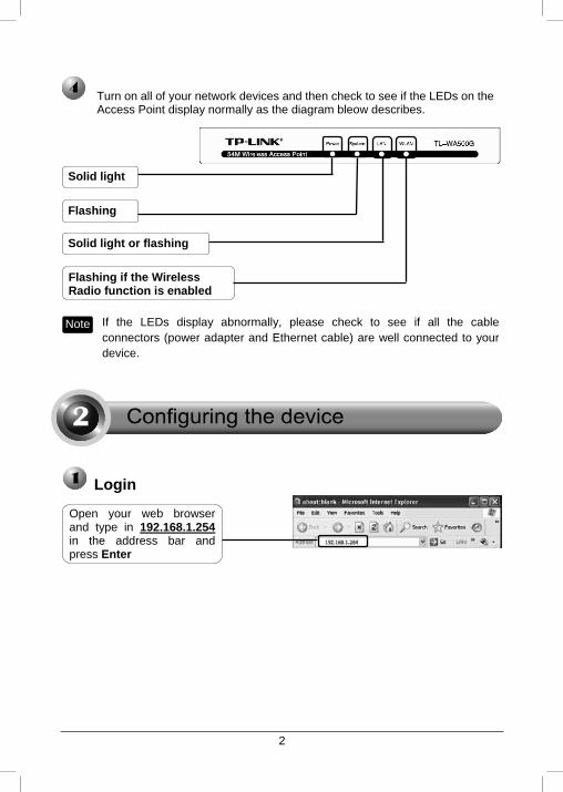
Plug the provided power adapter into the power jack on theback of the Access Point, and the other end to a standard electricalwall socket.
Note If the distance between the outlet and the Access Point is too long to supply the power, you can refer to the Power over Ethernet(PoE) solution in Appendix B: With PoE Setup.
2
Login
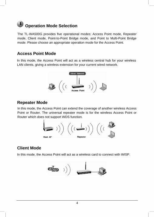
Open your web browser and type in 192.168.1.254 in the address bar and press Enter
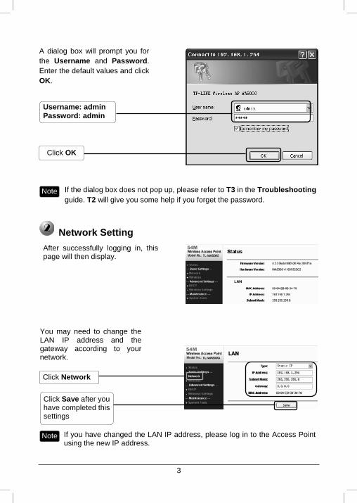
Note If the LEDs display abnormally, please check to see if all the cable connectors (power adapter and Ethernet cable) are well connected to your device.
Turn on all of your network devices and then check to see if the LEDs on the Access Point display normally as the diagram bleow describes.
Solid light
Flashing
Solid light or flashing
Flashing if the Wireless Radio function is enabled
3
Click OK
Network Setting
A dialog box will prompt you for the Username and Password.Enter the default values and click OK.
Note If the dialog box does not pop up, please refer to T3 in the Troubleshooting guide. T2 will give you some help if you forget the password.
Username: admin Password: admin
After successfully logging in, this page will then display.
You may need to change the LAN IP address and the gateway according to your network.
Click Save after you have completed this settings
Click Network
Note If you have changed the LAN IP address, please log in to the Access Point using the new IP address.
4
Operation Mode Selection
Access Point Mode
Repeater Mode
Client Mode
The TL-WA500G provides five operational modes: Access Point mode, Repeater mode, Client mode, Point-to-Point Bridge mode, and Point to Multi-Point Bridge mode. Please choose an appropriate operation mode for the Access Point.
In this mode, the Access Point will act as a wireless central hub for your wireless LAN clients, giving a wireless extension for your current wired network.
In this mode, the Access Point can extend the coverage of another wireless Access Point or Router. The universal repeater mode is for the wireless Access Point or Router which does not support WDS function.
In this mode, the Access Point will act as a wireless card to connect with WISP.
5
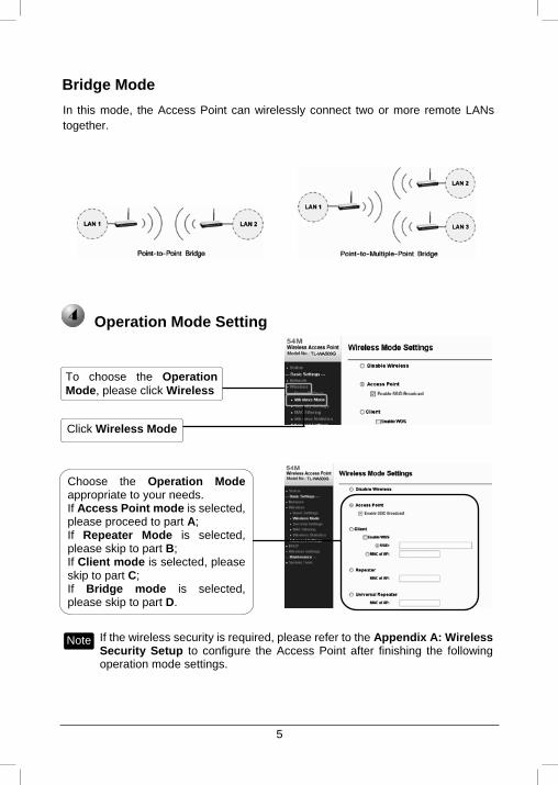
Bridge Mode
Operation Mode Setting
Click Wireless Mode
To choose the Operation Mode, please click Wireless
Choose the Operation Mode appropriate to your needs. If Access Point mode is selected, please proceed to part A; If Repeater Mplease skip to part B; If Client mode is selecskip to part C; If Bridge mplease skip to part D.
ode is selected,
ted, please
ode is selected,
Note If the wireless security is required, please refer to the Appendix A: Wireless Security Setup to configure the Access Point after finishing the following operation mode settings.
In this mode, the Access Point can wirelessly connect two or more remote LANs together.
6
Click Save
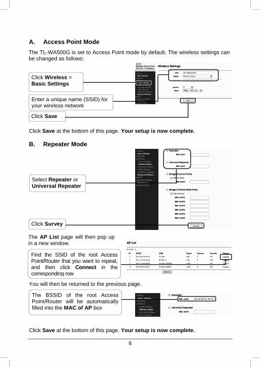
A. Access Point Mode
Click Save at the bottom of this page. Your setup is now complete.
B. Repeater Mode
Click Save at the bottom of this page. Your setup is now complete.
Select Repeater or Universal Repeater
Click Survey
Enter a unique name (SSID) for your wireless network
Click Wireless > Basic Settings
The TL-WA500G is set to Access Point mode by default. The wireless settings can be changed as follows:
The AP List page will then pop upin a new window.
Find the SSID of the root Access Point/Router that you want to repeat, and then click Connect in the corresponding row
The BSSID of the root Access Point/Router will be automatically filled into the MAC of AP box
You will then be returned to the previous page.
7
Click Survey at the bottom of the page
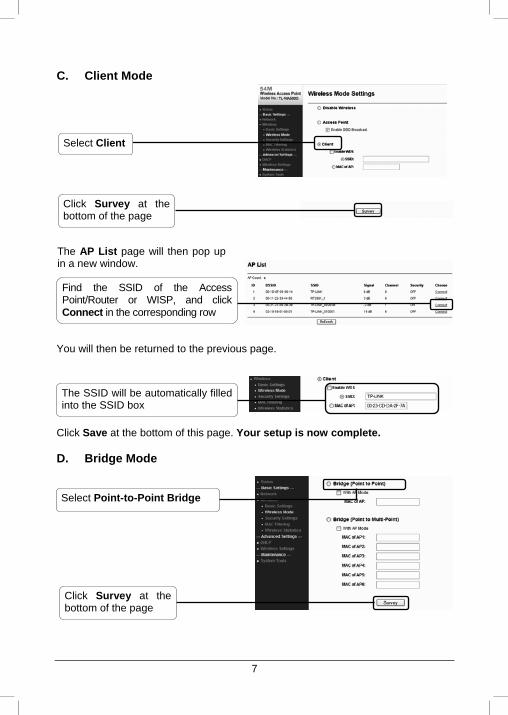
C. Client Mode
Click Save at the bottom of this page. Your setup is now complete.
D. Bridge Mode
Select Client
Find the SSID of the Access Point/Router or WISP, and click Connect in the corresponding row
The SSID will be automatically filled into the SSID box
You will then be returned to the previous page.
Select Point-to-Point Bridge
Click Survey at the bottom of the page
The AP List page will then pop upin a new window.
8
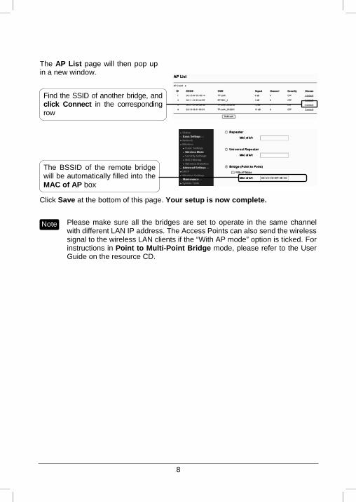
Click Save at the bottom of this page. Your setup is now complete.
Note Please make sure all the bridges are set to operate in the same channel with different LAN IP address. The Access Points can also send the wireless signal to the wireless LAN clients if the “With AP mode” option is ticked. For instructions in Point to Multi-Point Bridge mode, please refer to the User Guide on the resource CD.
The BSSID of the remote bridge will be automatically filled into the MAC of AP box
Find the SSID of another bridge, and click Connect in the corresponding row
The AP List page will then pop up in a new window.
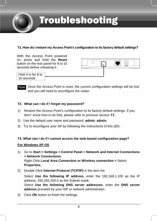
T1. How do I restore my Access Point’s configuration to its factory default settings?
With the Access Point powered on, press and hold the Reset button on the rear panel for 8 to 10 seconds before releasing it.
9
Hold it in for 8 to 10 seconds
Once the Access Point is reset, the current configuration settings will be lost and you will need to reconfigure the router.
Note
T2. What can I do if I forget my password?
1) Restore the Access Point’s configuration to its factory default settings. If you don’t know how to do that, please refer to previous section T1;
2) Use the default user name and password: admin, admin;
3) Try to reconfigure your AP by following the instructions of this QIG.
T3. What can I do if I cannot access the web-based configuration page?
For Windows XP OS
1) Go to Start > Settings > Control Panel > Network and Internet Connections > Network Connections; Right Click Local Area Connection or Wireless connection > Select Properties;
2) Double Click Internet Protocol (TCP/IP) in the item list.
Select Use the following IP address, enter the 192.168.1.100 as the IP address, 255.255.255.0 as the Subnet mask; Select Use the following DNS server addresses, enter the DNS server address provided by your ISP or network administrator;
3) Click OK button to finish the settings.
10
For Windows Vista OS
1) Go to Start > Settings > Control Panel > View network status and tasks; Click View Status at the right side > Properties;
2) Double Click Internet Protocol Version 4 (TCP/IPv4) in the item list;
Select Use the following IP address, enter the 192.168.1.100 as the IP address, 255.255.255.0 as the Subnet mask; Select Use the following DNS server addresses, enter the DNS server address provided by your ISP or network administrator;
3) Click OK button to finish the settings.
Now, try to log on to the Web-based configuration page again after the above settings have been configured. If you still cannot access the configuration page, please restore your Access Point’s factory default settings and reconfigure your Access Point following the instructions of this QIG. Please feel free to contact our Technical Support if the problem persists.
More detailed instructions for the IP address settings can be found in the User Guide on the resource CD.
Note
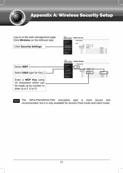
Log on to the web management page. Click Wireless on the leftmost side.
Click Security Settings
11
Select WEP
Select 64bit type for Key 1
Enter a WEP Key using 10 characters which can be made up by number or letter (a to f, A to F)
The WPA-PSK/WPA2-PSK encryption type is more secure and recommended, but it is only available for Access Point mode and client mode.
Note
Appendix A: Wireless Security Setup
12
Appendix B: With PoE Setup
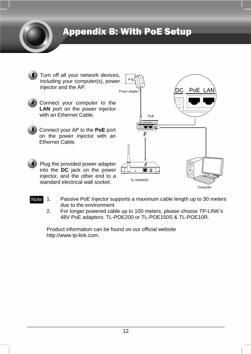
urn off all your network devices, cluding your computer(s), powe
Tin r
injector and the AP.
Connect your computer to the LAN port on the power injectorwith an Ethernet Cable.
Plug the provided power adapter into the DC jack on the power injector, and the other end to a standard electrical wall socket.
Connect your AP to the PoE port on the power injector with an Ethernet Cable.
Note 1. Passive PoE Injector supports a maximum cable length up to 30 meters due to the environment.
2. For longer powered cable up to 100 meters, please choose TP-LINK's 48V PoE adapters: TL-POE200 or TL-POE150S & TL-POE10R.
Product information can be found on our official website http://www.tp-link.com.
Technical Support For more troubleshooting help, go to:
www.tp-link.com/support/faq.asp
To download the latest Firmware, Driver, Utility and User Guide, go to: www.tp-link.com/support/download.asp
For all other technical support, please contact us by using the following details:
Global Tel: +86 755 26504400 E-mail: [email protected] Service time: 24hrs, 7days a week
Australia & New Zealand Tel: AU 1300 87 5465 NZ 0800 87 5465 E-mail: [email protected] Service time: 24hrs, 7days a week
Singapore Tel: +65 62840493 E-mail: [email protected] Service time: 24hrs, 7days a week Switzerland Tel: +41 (0)848 800998 (German service) E-mail: [email protected] Fee: 4-8 Rp/min, depending on rate of different time Service Time: Monday to Friday 9:00 AM to 6:00 PM. GMT+1 or GMT+2 (Daylight Saving Time) Malaysia Tel: 1300 88 875465 (1300 88TPLINK) Email: [email protected] 24 hours a day, 7 days a week
USA/Canada Toll Free: +1 866 225 8139 E-mail: [email protected] Service time: 24hrs, 7days a week UK Tel: +44 (0) 845 147 0017 E-mail: [email protected] Service time: 24hrs, 7days a week
Germany/Austria Tel: +49 1805 875465 (German Service) / +49 1805 TPLINK E-mail: [email protected] Fee: 0.14 EUR/min from the German fixed phone network and up to 0.42 EUR/min from mobile phone Service time: GMT+ 1 or GMT+ 2 (Daylight Saving Time in Germany) Except bank holidays in Hesse
Recommended