Santa Clara UniversityScholar Commons
Civil Engineering Senior Theses Engineering Senior Theses
6-2017
Garbage BeamPaula BackSanta Clara University, [email protected]
Mariela MurilloSanta Clara University, [email protected]
Follow this and additional works at: https://scholarcommons.scu.edu/ceng_senior
Part of the Civil and Environmental Engineering Commons
This Thesis is brought to you for free and open access by the Engineering Senior Theses at Scholar Commons. It has been accepted for inclusion in CivilEngineering Senior Theses by an authorized administrator of Scholar Commons. For more information, please contact [email protected].
Recommended CitationBack, Paula and Murillo, Mariela, "Garbage Beam" (2017). Civil Engineering Senior Theses. 54.https://scholarcommons.scu.edu/ceng_senior/54

i

ii
Garbage Beam
By Paula Back
Mariela Murillo
SENIOR DESIGN PROJECT REPORT
Submitted to The Department of Civil Engineering
of SANTA CLARA UNIVERSITY
In partial fulfillment of the requirements for the degree of Bachelor of Science in Civil Engineering
Santa Clara, California Spring 2017
iii
Paula Back Mariela Murillo
Department of Civil Engineering Santa Clara University
June 2017
ACKNOWLEDGMENTS
We would like to give a huge thank you to Dr. Tonya Nilsson who has advised and guided us
throughout this whole project. We would like to thank Brent Woodcock with the Structures Lab
for helping us throughout testing. This involved helping us order material, prepare the testing
samples and then test. And finally we would like to thank the Civil Engineering Department for
helping fund this project. Without that help we would not be able to try different things in the
search for the right material.

iv
ABSTRACT
Located in a hot desert climate area prone to strong winds, Egypt is made up of many homes
with little to no roofing leaving civilians exposed to the harsh elements. The overarching goal of
this project is to provide these homes with efficient and affordable roofing using concrete with
common garbage materials as reinforcement. Through preliminary testing and tensile testing it
was possible to narrow the focus down to two reinforcement materials: fish netting and plastic
grocery bags. From there final beam testing and pull out testing successfully demonstrated the
promise of these materials. With this, however, it is still important to continue research on the
materials and improve on the design in order to eventually create a one-way slab roof and pass
that design over to an NGO that can successfully implement it.

v
Table Of Contents Certificate of Approval i Title Page ii Acknowledgments iii Abstract iv Table of Contents v
I. Background 1 II. Materials Used 3
III. Design Criteria and Standards 7 A. Preliminary Testing 7 B. Tensile Testing 9 C. Design Specifications 10 D. Load Calculations 11 E. Design Calculations 12
IV. Description of the Designed Beam 15 A. Construction Process 15 B. Final Testing 17 C. Results 17 D. Compressive Strength Testing 20 E. Pull-Out Testing 21
V. Cost Estimate 24 VI. Relevant Non-Technical Issues 25
A. Political Constraints 25 B. Financial Constraints 25 C. Architectural Constraints 25 D. Possible Code Constraints 26
VII. Conclusion 27 VIII. References 28
Appendixes Appendix A A-1 Appendix B B-1 Appendix C C-1 Appendix D D-1

I. Background
Marginalized citizens of Egypt often have homes with little to no roofing while living in
a hot desert climate area prone to strong winds. Civilians are often left exposed to the harsh
elements. Construction with concrete in Egypt is very common, however, roofing systems made
of concrete require steel reinforcement that is expensive and usually inaccessible to the
impoverished. The residents often end up turning to quick fixes like plywood, pieces of sheet
metal or tarp as seen in Figure 1 . 1
Figure 1: Residents in a home in Egypt utilizing tarp as protection.
The overarching goal of this project was to provide these homes with efficient and
affordable roofing by designing for a one-way slab that an NGO or organization could
successfully implement. Initially the project was focused on using bamboo as the prime material.
After further research, it was discovered that all of the time, cost and energy saved in using
bamboo would be used toward the transportation of the material from a different country or
1 “Housing Poverty in Egypt,” https://www.habitatforhumanity.org.uk/what-we-do/where-we-work/europe-middle-east-and-africa/egypt
1

continent. The focus of the project, therefore, shifted to replacing the existing steel reinforcement
found in concrete with something more accessible: garbage.
Given that approximately 24 percent of the Egyptian population lives in substandard
housing conditions, one of the main constraints throughout design is cost . It is crucial that all 2
materials selected are easily found in a local dumpster or landfill and will not require any sort of
transportation from an outside provider. The concrete beams reinforced with the product also
must be effective in protecting residents from the harsh conditions while remaining intact.
2 “Housing Poverty in Egypt,” https://www.habitatforhumanity.org.uk/what-we-do/where-we-work/europe-middle-east-and-africa/egypt
2

II. Materials Used
Initially the project was focused on designing connections between the bamboo roofing
system and the existing house made of either concrete masonry unit (CMU) blocks or cob. These
roofing systems would look similar to that found in Figure 2 . Working with bamboo would 3
come with both advantages and disadvantages as can be seen in Table 1.
Figure 2: Initial roofing design possibility using bamboo.
Table 1: Advantages and disadvantages of using bamboo . 4
Bamboo
Advantages Disadvantages
● Low cost of production ● Compares in strength to concrete and
steel ● Lightweight ● Handles shear very well ● Fast growth
● Flammable ● Difficult to connect separate pieces ● Not local to Egypt ● Requires an expensive treatment
process to avoid rotting
3 “Good Home Design” http://cdn.goodshomedesign.com/wp-content/uploads/2015/05/Bamboo-Roof-5.jpg 4 Roach, Mary, “The Bamboo Solution,” http://discovermagazine.com/1996/jun/thebamboosolutio784 (June 1, 1996).
3

While bamboo is an exceptional material in terms of physical properties, the application
of it to this specific project was not optimal. Bamboo is a material that requires extensive
knowledge and experience in order to use it effectively and safely . It is not guaranteed that these 5
requirements will be met during construction in the marginalized areas of focus, especially
considering that resources such as an inspector are not widely available.
One of the most important pieces of this entire project was affordability. The closest
known supplier of bamboo is a farm in Nairobi, Kenya . That transportation process would not 6
only be expensive but would also leave a negative environmental impact.
The next option was to improve the existing design using concrete but since the high
costing steel reinforcement was the most inaccessible piece of the design, it was key to try to
replace that aspect with a material much more affordable and easy to find. In Cairo, the largest
city in Egypt, more than 15,000 tons of solid waste are produced every day and that number
continues to grow . With this fact came the idea to incorporate that garbage into the concrete as 7
the tensile reinforcement.
In some cases, plastic has been incorporated into concrete as a replacement to aggregate.
In one specific test it was found that there was a significant decrease in strength but also a
significant decrease in bulk density. One advantage of using the plastic as aggregate in this case,
was that the plastic did not absorb any water, reducing excess water . While the results of this 8
test were not ideal with respect to the strength of the concrete, they did offer promise in how the
5 Myers, Evan, “Structural Design of Bamboo in East Africa”, http://www.academia.edu/5108420/Structural_Design_of_Bamboo_in_East_Africa (2013). 6 Fielder Zack, et. al., “Bamboo Roofing System for Egyptian Houses” (2016), page 22 7 Zafar, Salman, “Garbage Woes in Cairo,” http://www.ecomena.org/tag/waste-management-in-egypt/ (November 2, 2016). 8 Maqbool Sadiq, Muhammad and Rafique Khattak, Muhammad, “Literature Review on Different Plastic Waste Materials Used in Concrete,” http://www.jetir.org/papers/JETIR1506020.pdf (June 2015).
4

plastic positively reacts to the concrete. Plastic is workable with concrete while still offering
some strength. More research simply needs to be done with respect to how much more plastic is
needed and how best this material should be incorporated into the concrete.
Along with plastic based materials, rubber from old tires was a viable alternative.
Recycled rubber tires have also been tested for their strength as an aggregate but not for their
tensile reinforcing strength. Similar to that of the plastic aggregate previously mentioned, the
strength of the concrete decreased. One published test noted losses of up to 85% in compressive
strength and up to 50% of the tensile strength. These cylinders, however, did not experience
brittle failure but instead a gradual failure . This fact offered promising data in that using the 9
material in its entirety could possibly help hold the concrete together for a longer time period.
Another material that is commonly found in everyday garbage are throwing nets for
fishing. It is estimated that approximately 10% of all marine debris is made up of “ghost nets” or
nets that are lost at sea . These nets are a material that can withstand the weight of hundreds of 10
fish at a time in some cases. It was therefore determined that this material could successfully
exhibit some sort of tensile strength.
As a result of these findings, the materials selected to test as tensile reinforcement were
plastic grocery bags, plastic soda bottles, plastic soda can rings, fish netting and rubber tires, as
can be seen below in Figure 3.
9 Eldin, Niel N., Senouci, Ahmed B., “Rubber-Tire Particles as Concrete Aggregate,” http://ascelibrary.org/doi/pdf/10.1061/(ASCE)0899-1561(1993)5:4(478) (1993). 10 “What are Ghost Nets?” http://www.marinemammalcenter.org/Get-Involved/events/ghost-below/ghost-nets.html?referrer=https://www.google.com/
5

Figure 3: Materials selected for testing.
6

III. Design Criteria and Standards
When designing the concrete beam, certain criteria and standards needed to be met before
final design and testing were complete. Five different types of materials were initially
investigated and tested but only two types were chosen for the final designs. Certain tests and
calculations were done in order to narrow down the selection.
A. Preliminary Testing
The first type of testing done was preliminary testing of a simple reinforced concrete
beam in order to better understand constructability, how the material would react with concrete,
and what kinds of peak loads each material would have. As seen in Figure 4 below, the molds
used were pre-fabricated with dimensions of 4”x4”x24”. The materials were placed in the beam
and held in place using dobies, which are tiny blocks of concrete with wiring.
Figure 4: Pre-fabricated molds using in preliminary testing.
Testing was done 14 days after the concrete was poured. Using the Tinius Olsen
Hydraulic Universal Testing Machine in the SCU structure lab, the five material beams were
7

tested, as well as a control beam using two No. 3 rebar. A three-point load test was used during
this testing because the primary focus was to look at behavior of material, constructability and
the peak load.
Figure 5 shows the embedment of the plastic soda can rings as reinforcing with concrete
after failure. The material had no problem binding with the concrete and was very difficult to
remove once testing was complete. This behavior was a good indicator of how the material could
easily be used as a reinforcement without the worry that it would just “slip out.”
Figure 5: The result of preliminary testing with the soda can rings.
Although soda bottles and soda can rings had some of the highest values in terms of peak
loads, as can be seen in Table 2, both were eliminated as testing materials because of challenges
with constructability. A great deal of caution was taken when dealing with the soda bottles and
rings to avoid damaging the materials, but realistically, materials pulled out of a dumpster,
8

landfill or off the streets will already be damaged in some way. For that reason, it was
determined that these materials would not perform as initially expected.
Table 2: Results from preliminary testing.
Material Tested Max Load (lbf)
Control (w/ (2) no. 3 rebar) 3430
Fish Net 1288
Soda Rings 983
Bottles + Rings 955
Grocery Bags 729
Tire 617
B. Tensile Testing
Tests on the tensile strength of the remaining three (3) materials (tire, fish netting and
plastic grocery bags) were performed. This testing process entailed securing both ends of the
material on the 10 Kip machine and pulling until failure. Values for Force vs. Deformation were
recorded during the test. This data was converted to Stress vs. Strain and plotted as shown in
Appendix A. The values for Modulus of Elasticity (E) from these plots can be found in Table 3.
Table 3: Values for Modulus of Elasticity and yield stresses found from tensile testing.
9

Given the results of this test, rubber tire was eliminated from the list of materials tested.
The Modulus of Elasticity was too small in comparison to that of concrete which is 2,850,000
psi. This meant that the rubber tires were too flexible, resulting in a mismatch of stiffnesses. The
rubber tire would not even be engaged before the concrete failed. Following this test, the only
materials remaining were fish netting and plastic grocery bags.
C. Design Specifications
Before beginning to calculate and design the final beams for testing, there were certain
specifications that needed to be followed. The International Building Code (IBC) of 2015, is a
set of code and standards that multiple countries use in order to design commercial, residential
and other types of buildings. This code is used in both the United States and Egypt, our country
of focus. The IBC was also recommended by a faculty member, Dr. Hisham Said, who is from
Egypt. The IBC was used to find certain live loads were applied to the beam, which can be found
in Appendix B.
Another standard used was the ACI 318-14, which contains the building code
requirements for structural concrete. This report was used to calculate the moment capacity of
each beam. Though the code moment capacity formulas are based on using steel reinforcement,
it is a starting point because no equations or formulas currently exist for waste.
During testing, the ASTM four-point load test was used in order to find the maximum
moment. The reason this test was used was because the maximum moment is constant over a
larger area. This helps in identifying stress where the failure initiated. The test setup can be seen
in Figure 6.
10

Figure 6: Diagram of a four-point load test.
D. Load Calculations
Before calculating how much material was needed for a concrete beam, the first step was
to calculate how much load each beam needed to hold. Using the IBC of 2015 and the tables
found in Appendix B, there were two types of live loads roofs were expected to withstand; one
being a uniform load of 20 psf and the other being a concentrated load of 300 pounds.
The dimensions of the beams built were 7” x 10” x 60”. Using these dimensions, the
moment of each beam per load was calculated. Below, Equation 1 and 2 were used to find
moment of the beam with concentrated and uniform loads respectively. In Appendix D, the hand
calculations can be found.
Equation 1: Moment Demand of a Beam With a Concentrated Load.
oment (concentrated load)M : 4P L (1)
P= Concentrated load (lbs)
L= Length of beam (ft) w= weight of uniform load (lb/ft)
Equation 2: Moment Demand of a Beam With an Uniform Load.
oment (uniform load)M : 8wL2
(2)
L= Length of beam (ft) w= weight of uniform load (lb/ft)
11

The moment for concentrated load was found to be 375 lb-ft and the uniform load was 36
lb-ft. The beams designed would be for the extreme case which is the concentrated load. In order
to calculate the total moment demand, the moment of the dead load had to be found. To be
conservative, the self-weight of concrete was assumed to be 150 pcf, and using Equation 2, the
moment was calculated to be 228 lbs-ft, and therefore the total moment demand equaled 603
lb-ft.
E. Design Calculations
The method of transformed sections was used in order to determine the proper placement
of materials in the beam that maximized its tensile strength capacity. Since the concrete and
material used were expected to act as a single member, this method was used to transform the
“waste” materials into concrete. Using this method, variables such as d and a were found. In
Figure 7 below, d is shown being the depth from the outer compression fiber, meaning the top of
the beam, to the centroid of reinforcement. The variable a, is shown as the approximate length of
the compression zone, assuming that the distribution of the compressive stress in the concrete is
shaped more like a block than a curve.
Figure 7: Diagram of a compression stress block . 11
11 “Strength of Reinforced Concrete Beams” http://www.ce.memphis.edu/1112/notes/project_2/beam/reinforced_concrete_beams.pdf
12

A value for a was solved for in order to calculate the moment capacity of each beam.
Equations 3 and 4 below were combined to get the final moment capacity, Equation 5.
Equation 3: Compression Zone Length.
a = A ×fmat y
0.85×f ×b′c(3)
Amat=Area of material (in 2) fy= stress of material (psi)
f’ c= stress of concrete (2500 psi) b= base (in.)
Equation 4: Moment Capacity of Beam with respect to a.
d )M = Amat × f y × ( − 2a (4)
Amat=Area of material (in 2)
a= length of compression zone (in.) d= depth from the compression fiber to centroid of material (in.)
fy= stress of material (psi)
Equation 5: Final Moment Capacity of a Beam.
d .59 )M = Amat × f y × ( − 0 ×f ×b′c
A ×fmat y (5)
Amat=Area of material (in 2) fy= stress of material (psi)
d= depth from the compression fiber to centroid of material (in.) f’ c= stress of concrete (2500 psi)
b= base (in.)
Once all the variables and formulas were found, it was then a process of trial and error.
Appendix D shows all of the hand calculations that were done in order to solve for moment
capacity. The main goal was to find out how many pieces of material it took to calculate a
13

moment capacity greater than the demand. In Table 4 below, the results for plastic grocery bags
are shown, and in Appendix C, the results of the fish netting are shown.
Table 4: Example of the iteration process with plastic grocery bags.
Plastic Grocery Bag Iterations
# of pieces 2 3 4
Area with number of pieces 0.02 0.03 0.04
Allowable Stress (psi) 25,000 25,000 25,000
d (in) 8 8 8
Moment Capacity (lb-ft) 315 470 625
Check N.G. N.G. OK
The final results of design calculations were that four (4) plastic grocery bags would be
needed to attain a moment capacity greater than the demand. What this result means is that the
cross-sectional area of four (4) plastic bags was needed. For fish netting, the amount of material
needed was eight (8) pieces. Now that calculations were complete, the next step was building the
beams.
14

IV. Description of the Designed Beam
A. Construction Process
With the remaining two materials, fish netting and plastic grocery bags, six beams (three
with each material) were constructed using concrete with a 2500 psi mix design. For both
materials, a drill was used to twist the pieces into rods.
For the grocery bags, one rod consisted of 16 bags of which a cross-section had two (2)
bags, leaving a total of 32 bags in the concrete beam, as seen in Figure 8. Two rods were then
placed into the form and kept taut by drilling holes in the formwork and running a string through
to hold the bags.
Figure 8: The plastic grocery bag rods set into the formwork.
The fish netting consisted of four (4) pieces of material (each 10 inches wide) per rod.
Once the fish netting was twisted together, the rods were placed in the beam and kept taut using
dobies as shown in Figure 9.
15

Figure 9: Fish netting rod set into the formwork.
The concrete was then poured and the beams were left to cure for 28 days. During this
time period, the beams were sprayed with water at least once per week to ensure the concrete did
not dry out. Figure 10 shows the poured concrete beams sitting in the formwork.
Figure 10: Poured concrete beams sitting in the formwork.
16
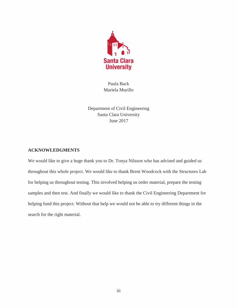
B. Final Testing
On April 25, 2017 the beams were removed from the molds. Testing was done using a
four-point test on the Tinius Olsen. The testing apparatus can be seen in Figure 11.
Figure 11: Example of the testing apparatus for the full size beams.
Load was carefully applied at about 150 pounds/second with the help of Brent Woodcock
in the Structures Lab. All six beams were tested until failure.
C. Results
In all of the tests except one, the tensile reinforcement remained intact while the concrete
failed around it. One of the plastic grocery bags snapped during the test, resulting in full failure.
An example of both materials are shown in Figures 12 and 13.
17

Figure 12: Failed beam with fish netting reinforcement.
Figure 13: Failed beam with grocery bag reinforcement.
The results of this test were then used to determine the maximum moment of each beam.
Equation 6, below, was used in order to find the maximum moment using the maximum load.
That result would then be compared to the moment demand of 603 lb-ft, as well as the theoretical
moment capacity. These values can be found in Tables 5 and 6 below.
18

Equation 6: Maximum Moment Using Maximum Load.
aximum MomentM = 4P ×(S −S )O I (6)
P= maximum load (lbs)
SO= spacing of furthest pins (in.) SI= spacing of closest pins (in.)
Table 5: Resulting calculated values from final beam test for fish netting.
Fish Netting Max Load (lbf) Moment (lb-ft) Stress at Failure (psi)
Beam 1 3970 3220 2.44x10⁵
Beam 2 3970 3230 2.44x10⁵
Beam 3 1560 1270 0.96x10⁵
Average 3170 2570 1.95x10⁵
Standard Deviation 1390 1130 0.86x10⁵
Theoretical Moment 994
Table 6: Resulting calculated values from final beam test for plastic grocery bags.
Plastic Bag Max Load (lbf) Moment (lb-ft) Stress at Failure (psi)
Beam 1 2110 1710 1.06x10⁵
Beam 2 2820 2300 1.42x10⁵
Beam 3 2080 1690 1.04x10⁵
Average 2340 1900 1.17x10⁵
Standard Deviation 420 340 0.21x10⁵
Theoretical Moment 625
19

D. Compressive Strength Testing
All of the beams, even the weakest one that failed at approximately 1500 lbs, exceeded
the theoretical moment capacities. The beams did better than expected or calculated, and could
have potentially done better if the concrete had not failed first. This fact led to further testing to
determine the actual compressive strength of the concrete used.
Three concrete cylinders were tested, and the the compressive strength was found.
Through calculations and design, the compressive strength was assumed to be 2500 psi.
However tests showed an average compressive strength of 1,020 psi as shown in Table 7.
Table 7: Results from Cylinder Testing.
Concrete Cylinders Max Load (lbf) f'c (psi)
1 12,515 1,000
2 18,000 1,400
3 8,300 660
Average 13,000 1,020
Since the compressive strength was less than expected, the theoretical moment capacities
of each type of material were recalculated. These capacities can be seen in Table 8 and 9 below.
Table 8: Calculated moment capacity values from cylinder testing for grocery bags.
Plastic Grocery Bags
Original Theoretical Moment Capacity (lb-ft) 625
Recalculated Theoretical Moment Capacity (lb-ft) 622
20

Table 9: Calculated moment capacity values from cylinder testing for fish netting.
Fish Netting
Original Theoretical Moment Capacity (lb-ft) 994
Recalculated Theoretical Moment Capacity (lb-ft) 984
The recalculated theoretical moments decreased, and therefore it does not affect
calculations or design due to the fact that the actual beams tested exceeded the theoretical
capacities.
E. Pull-Out Testing
Steel reinforcement bars are often ribbed in order to facilitate adhesion with the concrete.
This grip keeps the rebar from being pulled out when a load is applied. This pull out strength was
a concern when dealing with the plastic grocery bags and fish netting because of this issue with
adhesion. In order to test the pull-out strength of these materials, six (6) cylinders were created,
three (3) for each material. Both the fish netting and the plastic grocery bags were embedded
about six (6) inches into a 2500 psi concrete cylinder, leaving about two (2) inches of cover,
while another six (6) inches were sticking out. One (1) knot was placed inside the concrete at the
bottom. A piece of No. 3 steel reinforcing bar was placed horizontally along the bottom to
facilitate testing. The cylinders were then placed in a lime bath for 28 days to allow for curing.
Pull-out testing was done using the 10-kip machine in the structures lab at Santa Clara
University. The rebar placed through the cylinder was attached to the machine while the material
was fastened at the opposite end. An example using the fish netting test can be found in Figure
14.
21

Figure 14: Testing Apparatus for pull-out test using fish netting.
The results of the pull-out tests can be found in Tables 10 and 11.
Table 10: Pull-Out Test results for fish netting.
Fish Netting Pull-Out Test
Test # Pull-Out Load (lbs) Pulled Out?
1 260 NO
2 260 NO
3 300 NO
Average 273
22

Table 11: Pull-Out Test results for grocery bag.
Grocery Bag Pull-Out Test
Test # Pull-Out Load Pulled Out?
1 90 NO
2 30 YES
3 75 YES
Average 65
In all tests, both materials were substantially pulled out. For the fish netting, the material
did not entirely pull out from the concrete cylinder in any test. On the other hand, for two out of
the three grocery bag tests, the material was entirely pulled out. For tests 1,2 and 3 of the fish
netting tests and test 1 of the plastic grocery bag test in which the material stayed in the cylinder,
the test was stopped because the machine had hit its full capacity in terms of distance to pull.
Given the values in Tables 10 and 11, fish netting proved to be stronger in terms of
pull-out strength. A theory for this result is that because fish netting has more “ribbing” or is
more coarse, it creates more adhesion with the concrete. Plastic grocery bags, even though they
were twisted and not completely smooth, were more smooth than fish netting.
23

V. Cost Estimate
For the purposes of this project, different materials were purchased for the different
phases of testing. The costs of these materials can be found in Table 12 below.
Table 12: Materials purchased and used for testing.
Item Purchased Project Cost Typical Cost
Throwing Net for Fishing $150 $0
Plastic Grocery Bags $50 $0
Rubber Tires $0 $0
Plastic Soda Bottles $20 $0
Plastic Soda Rings $0 $0
Portland Cement (4-94 lb bags)
$0 $40
Plywood/Lumber $100 $100
Total = $320 = $140
Most of these materials were purchased new to determine how the tests would result
when the materials were in the best condition. Materials like the used rubber tires, however, were
donated from a local bike shop.
Realistically the only materials that should be purchased when implementing this project
would be the Portland Cement and any lumber needed for formwork. As of May 2017, the cost
of cement in Egypt is about 735 Egyptian Pounds per ton, equivalent to about $40 US Dollars
per ton . The remaining materials are to be pulled (in the best condition possible) from local 12
landfills, dumpsters or off the streets, free of charge.
12 “Cement Egypt,” http://cementegypt.com/en/price (May, 2017).
24
VI. Relevant Non-Technical Issues
A. Political Constraints
Egypt is a country currently led by Abdel Fattah al-Sisi who removed his predecessor,
President Mohammed Morsi, from office through a coup. Throughout its history, Egypt has been
the setting of many political uprisings with one of the most memorable being “Arab Spring” in
2011. The U.S. Department of State warns on their website for tourists to be cautious of political
protests that can begin out of nowhere and often become violent. With such heated political
conditions and possible aversion towards foreigners, it was not possible to actually travel to the
country to get a first hand look at the issue. Instead, research was done in the United States using
first hand accounts and existing knowledge and documentation.
B. Financial Constraints
Funding of $800 was granted from the Engineering Department at Santa Clara University
in order to pay for materials for this project. Budgeting was also crucial because affordability is
such a large part of the design. It was important to mimic the fact that those implementing this
project abroad would have limited money and resources.
C. Architectural Constraints
In order to create an efficient design that will be welcomed by the communities that are
being served, it is crucial to look at existing architecture in these areas. Implementing a roof that
stands out may call unwanted attention and lead to conflict within the community in some way.
The idea is to create something that will blend in as much as possible and keep to the existing
architectural culture of the area.
25

D. Possible Building Code Constraints
In this case, the International Building Code was used as the primary source for codes
mainly due to the fact that it is used in Egypt as well. The American Society for Testing and
Materials (ASTM) standards were also used as a guide. More research, however, is needed to
determine how applicable these guides are in Egypt and adapt as necessary.
26

VII. Conclusion
Following testing, there were promising results for the fish netting and plastic grocery
bags as tensile reinforcement in concrete to be used for roofing systems in Egypt. The materials
surpassed the theoretical moments while also meeting the moment demand. In terms of pull out
strength, however, both materials have some more work that needs to be done with respect to
how to improve on the adhesion to the concrete.
Unfortunately it was not possible to calculate the one-way slab roof because more
research needed to be done in order to comfortably and responsibly do so.
It would be of great interest for a group in the coming years to take on this project and
continue research. The hope is to eventually give a fully functioning and safe design to an NGO
or organization that can successfully implement this project not only in Egypt but in many
developing countries.
27

VIII. References
[1-2]. “Housing Poverty in Egypt,” https://www.habitatforhumanity.org.uk/what-we-do/where-we-work/europe-middle-east-and-africa/egypt [3] “Good Home Design” http://cdn.goodshomedesign.com/wp-content/uploads/2015/05/Bamboo-Roof-5.jpg [4] Roach, Mary, “The Bamboo Solution,” http://discovermagazine.com/1996/jun/thebamboosolutio784 (June 1, 1996). [5] Myers, Evan, “Structural Design of Bamboo in East Africa”, http://www.academia.edu/5108420/Structural_Design_of_Bamboo_in_East_Africa (2013). [6] Fielder Zack, et. al., “Bamboo Roofing System for Egyptian Houses” (2016), page 22 [7] Zafar, Salman, “Garbage Woes in Cairo,” http://www.ecomena.org/tag/waste-management-in-egypt/ (November 2, 2016). [8] Maqbool Sadiq, Muhammad and Rafique Khattak, Muhammad, “Literature Review on Different Plastic Waste Materials Used in Concrete,” http://www.jetir.org/papers/JETIR1506020.pdf (June 2015). [9] Eldin, Niel N., Senouci, Ahmed B., “Rubber-Tire Particles as Concrete Aggregate,” http://ascelibrary.org/doi/pdf/10.1061/(ASCE)0899-1561(1993)5:4(478) (1993). [10] “What are Ghost Nets?” http://www.marinemammalcenter.org/Get-Involved/events/ghost-below/ghost-nets.html?referrer=https://www.google.com/ [11] “Strength of Reinforced Concrete Beams” http://www.ce.memphis.edu/1112/notes/project_2/beam/reinforced_concrete_beams.pdf [12] “Cement Egypt,” http://cementegypt.com/en/price (May, 2017).
28

Appendix A
Tensile Testing Graphs
A-1

A-2

Appendix B
Standards and Code Requirements
B-1

Appendix C Calculation Results
grocery bag fish net
length (in) 12 length (in) 5 base(width) (in) 12 base(width) (in) 2.5 thickness (in) 0.0008 diameter (in) 0.01
area (in^2) 0.0096 area (in^2) 0.00337
7 Yield Stress (psi) 24,528 Yield Stress (psi) 55,809
E (psi) 150,805 E (psi) 222,719 number of pieces 4 number of pieces 8
area with number of pieces 0.0384
area with number of pieces 0.0270
n 0.0529 n 0.0781 A'mat 0.00203 A'mat (in^2) 0.00211
d 8.00 d (in) 7.96 x (in) 0.068 x (in) 0.069
yt 7.93 yt (in) 7.89 I(transformed) in^4 0.129 I(transformed) in^4 0.132
Moment in Beam (lb-in) 7,504 Moment in Beam (lb-in) 11,926 Moment in Beam (lb-ft) 625 Moment in Beam (lb-ft) 994
Check compared to charts good Check compared to charts good
C-1

Appendix D
Detailed Calculations A. Modulus of Elasticity Formulas:
E = σ ÷ ε
E= Young’s Modulus (psi) σ= Tensile Stress (psi) ε= Tensile Strain Grocery Bag:
est 1 0, 00 psiT : 0.07349833.3 = 9 0
est 2 44, 79 psiT : 0.05669944.4 = 1 2
est 3 07, 50 psiT : 0.04179555.6 = 2 6
Rubber Tire: est 1 , 06 psiT : 576.7
0.1129 = 7 5 est 2 , 99 psiT : 190.6
0.0501 = 5 4 est 3 , 06 psiT : 428.6
0.0554 = 9 3 Fish Netting:
est 1 , 34, 91 psiT : 0.053354000 = 6 5 0
est 2 , 65, 09 psiT : 0.084265000 = 2 4 9
est 3 , 33, 33 psiT : 0.065176000 = 3 0 3
B. Moment Demand Formula:
oment (concentrated load)M : 4P L
oment (uniform load)M : 8wL2
P= Concentrated load (lbs) L= Length of beam (ft) w= weight of uniform load (lb/ft)
D-1
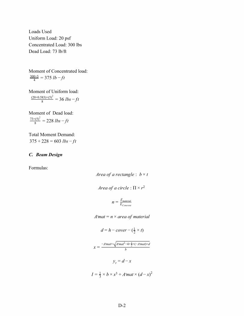
Loads Used Uniform Load: 20 psf Concentrated Load: 300 lbs Dead Load: 73 lb/ft Moment of Concentrated load:
75 lb t4300×5 = 3 − f
Moment of Uniform load:
6 lbs t 8(20×0.583)×(5)2
= 3 − f Moment of Dead load:
28 lbs t873×(5)2
= 2 − f Total Moment Demand:
75 28 03 lbs t3 + 2 = 6 − f C. Beam Design Formulas:
rea of a rectangle bA : × t
rea of a circle A : Π × r2
n = EmaterialEConcrete
mat rea of materialA′ = n × a
over )d = h − c − ( 2
1 × t
x = b−A mat+′ √A mat −4× ×(−A mat)×d′ 2
2b ′
yt = d − x
matI = 31 × b × x3 + A′ × (d )− x 2
D-2

d .59 )M = Amat × f y × ( − 0 ×f ×b′c
A ×fmat y
b= base (in.) t= thickness (in.) r= radius (in) n= factor Ematerial= modulus of elasticity of material (psi) Econcrete= modulus of elasticity of concrete (2,850,000 psi) d= depth from the compression fiber to centroid of material (in.) h= height (in.) cover= 2 in. x= length of compression zone (in.) I= moment of inertia (in.4) M= moment capacity of beam (lbs-in) fy= stress of material (psi) f’c= stress of concrete (2500 psi) Grocery Bags:
rea of one piece of material 2 .0008 .0096 in.A = 1 × 0 = 0 2
otal area (4 pieces) .0096 .0384 in.T = 4 × 0 = 0
.0529n = 150,8052,850,000 = 0
mat .0529 .0384 .00203 in.A′ = 0 × 0 = 0 2
0 5 .0008) in.d = 1 − 2 − 2
1 × ( × 0 = 8
.068 in.x = 7−0.00203+√0.00203 −4× ×(−0.00203)×82
27
= 0
.068 .93 in.yt = 8 − 0 = 7
.00203 .129 in.I = 31 × 7 × 0.0683 + 0 × (8 .068)− 0 2 = 0 4
.0384 4, 28 8 .59 ) , 04 lb n 25 lb tM = 0 × 2 5 × ( − 0 ×
2500×7
0.00203×24,528 = 7 5 − i → 6 − f
D-3

Fish Netting:
rea of one piece of material 3 .0034 in.A = Π × 0.0052 × 4 = 0 2
otal area (8 pieces) .0034 .0270 in.T = 8 × 0 = 0 2
.0781n = 222,7192,850,000 = 0
mat .0781 .0270 .00211 in.A′ = 0 × 0 = 0 2
0 8 .01) .96 in.d = 1 − 2 − 2
1 × ( × 0 = 7
.069 in.x = 7−0.00211+√0.00211 −4× ×(−0.00211)×7.962
27
= 0
.96 .069 .89 in.yt = 7 − 0 = 7
.00211 .132 in.I = 31 × 7 × 0.0693 + 0 × (7.96 .069)− 0 2 = 0 4
.0270 5, 09 7.96 .59 ) 1, 26 lb n 94 lb tM = 0 × 5 8 × ( − 0 ×
2500×7
0.00211×55,809 = 1 9 − i → 9 − f
D. Final Beam Maximum Moment Calculations
aximum MomentM = 4P ×(S −S )O I
P= maximum load (lbs) SO= spacing of furthest pins (in.) SI= spacing of closest pins (in.) Grocery Bags:
(beam 1) 0543 lbs n. 712 lbs tM = 42107×(48−9) = 2 − i → 1 − f
(beam 2) 7554 lbs n. 296 lbs tM = 4
2826×(48−9) = 2 − i → 2 − f
(beam 3) 0319 lbs n. 693 lbs tM = 42084×(48−9) = 2 − i → 1 − f
D-4

Fish Netting:
(beam 1) 8659 lbs n. 222 lbs tM = 43965×(48−9) = 3 − i → 3 − f
(beam 2) 8747 lbs n. 229 lbs tM = 4
3974×(48−9) = 3 − i → 3 − f
(beam 3) 5210 lbs n. 268 lbs tM = 41560×(48−9) = 1 − i → 1 − f
E. Concrete Cylinders Compressive Strength
F ′c = AP
F’c= compressive strength of concrete (psi) P= maximum load (lbs) A= Area of cylinder (in.2)
(cylinder 1) 96 psiF ′c = 12.5712514 = 9
(cylinder 2) 384 psiF ′c = 12.57
17393 = 1
(cylinder 2) 59 psiF ′c = 827812.57 = 6
F. Recalculated Theoretical Moment Capacities
d .59 )M = Amat × f y × ( − 0 ×f ×b′c
A ×fmat y
Grocery Bag:
.0384 4, 28 8 .59 ) , 60 lb n 22 lb tM = 0 × 2 5 × ( − 0 ×1013×7
0.00203×24,528 = 7 4 − i → 6 − f
Fish Netting:
.0270 5, 09 7.96 .59 ) 1, 13 lb n 84 lb tM = 0 × 5 8 × ( − 0 ×1013×7
0.00211×55,809 = 1 8 − i → 9 − f
D-5
Recommended