8/12/2019 59811139 CCNA Quick Reference Sheets
http://slidepdf.com/reader/full/59811139-ccna-quick-reference-sheets 1/311
CCNAQuick Reference Sheets
ICND1
1 Building a Simple Network .....................................3
2 Understanding TCP/IP ..........................................17
3 Understanding Ethernet........................................32
4 LAN Network Topologies......................................42
5 Operating Cisco IOS..............................................51
6 Configuring a Cisco Switch..................................57
7 Extending the LAN.................................................78
8 Exploring the Functions of Routing......................88
9 Configuring a Cisco Router................................105
10 Understanding WAN Technologies.................130
11 RIP Routing........................................................153
12 Managing Your Network Environment ...........164
ICND2
1 Implementing VLANS and Trunks .....................1722 Redundant Switching and STP..........................183
3 Troubleshooting Switched Networks...............203
4 Routing Operations and VLSM ..........................210
5 Implementing OSPF in a Single Area................230
6 Implementing EIGRP...........................................247
7 Managing Traffic with ACLs...............................257
8 Managing Address Space withNAT and IPv6 .......................................................270
9 Establishing SerialPoint-to-Point Connections ...............................281
10 Establishing Frame Relay Connections..........291
11 Introducing VPN Solutions...............................302
Eric RivardJim Doherty
ciscopress.comFrom the Library of MARCO A. ZUNIGA C.

8/12/2019 59811139 CCNA Quick Reference Sheets
http://slidepdf.com/reader/full/59811139-ccna-quick-reference-sheets 2/311
About the AuthorsEric Rivard , A+, MCSE, CCNP, CCSE, is an IT manager at Valley Center Municipal Water District. Over the pastseveral years, he has taught professionals in both academic and industry settings topics on SCADA, Windows, network-ing, and IT security. Before joining Valley Center MWD, Eric was a network and security consultant in the San Diegoarea. He is the author of the first and second edition of the CCNA Flash Cards and Exam Practice Pack . He holds a B.S.in information technology from the University of Phoenix. He lives with his wife and two children in Oceanside, CA.
Jim Doherty is currently the director of strategic marketing with Symbol Technologies. Prior to joining Symbol, Jimworked at Cisco Systems, where he led marketing campaigns for IP telephony, and routing and switching. Over the pastseveral years, he has taught professionals in both academic and industry settings on a broad range of topics, includingnetworking, electric circuits, statistics, and wireless communication methods. Jim is the coauthor of Cisco Networking
Simplified and wrote the “Study Notes” section of the CCNA Flash Cards and Exam Practice Pack . Jim holds a B.S. inelectrical engineering from N.C. State University and an MBA from Duke University. Jim also served in the United StatesMarine Corps, where he earned the rank of sergeant before leaving to pursue an education.
[ 2 ]
© 2008 Cisco Systems, Inc. All rights reserved. This publication is protected by copyright. Please see page 311 for more details.
CCNA Quick Reference Sheets by Eric Rivard and Jim Doherty
From the Library of MARCO A. ZUNIGA C.

8/12/2019 59811139 CCNA Quick Reference Sheets
http://slidepdf.com/reader/full/59811139-ccna-quick-reference-sheets 3/311
SECTION 1
Building a Simple Network
ICND1Part I: Summarizing Network Technology
Section 1Building a Simple Network
Exploring the Functions of NetworkingA network is a collection of devices and end systems.
Networks consist of computers, servers, and network devices, such as switches and routers, that can communicate witheach other.
Common Physical Components of a NetworkFigure 1-1 shows the four major categories of physical components on a network:
n Personal computers (PCs): Send and receive data and are the endpoints of the network.
n Interconnections: Are the components that provide a means for data to travel across the network. This includesnetwork interface cards (NIC), network media, and connectors.
n Switches: Provide network access for the PCs.
n Routers: Interconnect networks.
[ 3 ]
© 2008 Cisco Systems, Inc. All rights reserved. This publication is protected by copyright. Please see page 311 for more details.
CCNA Quick Reference Sheets by Eric Rivard and Jim Doherty
From the Library of MARCO A. ZUNIGA C.
8/12/2019 59811139 CCNA Quick Reference Sheets
http://slidepdf.com/reader/full/59811139-ccna-quick-reference-sheets 4/311
SECTION 1
Building a Simple Network
Networking FundamentalsNetworking has its own jargon and common terms. The following terms are used throughout the industry and appearmany times in this study guide:
n Network interface card (NIC): Connects a computer to a LAN.
n Medium: The physical transport used to carry data. Most of the time, this can be just a cable (twisted-pair or fiber),but it also includes air (for wireless transmission).
n Protocol: A set of communication rules used by computer or network devices.
n Cisco IOS Software: The most widely deployed network system software. Cisco IOS services include basic connec-tivity, security, network management, and other advanced services.
n Client: A computer or program that requests information from a server.
n Server: A computer or program that provides services of information to clients.
n Network operating system (NOS): Refers to the operating system running on servers. This includes Windows 2003Server, Novell NetWare, UNIX, and Linux.
n Connectivity device: Any device that connects cable segments, connects two or more small networks into a largerone, or divides a large network into small ones.
[ 4 ]
© 2008 Cisco Systems, Inc. All rights reserved. This publication is protected by copyright. Please see page 311 for more details.
CCNA Quick Reference Sheets by Eric Rivard and Jim Doherty
InterconnectionInterconnection
Router Switch
PCInternet
PC
FIGURE 1-1Network Components
From the Library of MARCO A. ZUNIGA C.

8/12/2019 59811139 CCNA Quick Reference Sheets
http://slidepdf.com/reader/full/59811139-ccna-quick-reference-sheets 5/311
SECTION 1
Building a Simple Network
n Local-area network (LAN): A network confined to a small geographic area. This can be a room, building, orcampus.
n Wide-area network (WAN): Interconnects LANs using leased carrier lines or satellite technology over a largegeographic location.
n Physical topology: A network’s physical shape. These shapes include linear bus, ring, star, and mesh.
n Logical topology: The path that data takes from one computer to another.
Why Network Computers?One of the primary functions of a network is to increase productivity by linking computers and computer networks.
Corporate networks are typically divided into user groups, which are usually based on groups of employees. Remote-access locations, such as branches, home offices, and mobile workers, usually connect to the corporate LAN using aWAN service.
Resource-Sharing Functions and BenefitsNetworks allow users to share resources and data. Major resources that are shared are as follows:
n Data and applications: Consist of computer data and network-aware applications such as e-mail.
n Resources: Include input and output devices such as cameras and printers.
n Network storage: Consists of directly attached storage devices (physical storage that is directly attached to acomputer and shared server), network attached storage, and storage area networks.
n Backup devices: Devices that back up files and data from multiple computers.
[ 5 ]
© 2008 Cisco Systems, Inc. All rights reserved. This publication is protected by copyright. Please see page 311 for more details.
CCNA Quick Reference Sheets by Eric Rivard and Jim Doherty
From the Library of MARCO A. ZUNIGA C.

8/12/2019 59811139 CCNA Quick Reference Sheets
http://slidepdf.com/reader/full/59811139-ccna-quick-reference-sheets 6/311
SECTION 1
Building a Simple Network
Networking ApplicationsNetworking applications are computer programs that run over networks.
Network User ApplicationsNetwork user applications include the following:
n E-mail
n Web browsers
n Instant messaging
n Collaboration
n Databases
Categories of Network ApplicationsNetwork applications function in one of three ways, with each application function affecting the network in different ways:
n Batch applications: Started by a human and complete on their own without further interaction. FTP and TFTP areexamples.
n Interactive applications: Include database updates and queries. A person requests data from the server and waits fora reply. Response time is typically more dependent on the server than the network.
n Real-time applications: Include Voice over IP (VoIP) and video. Network bandwidth is critical because these appli-cations are time critical. Quality of service (QoS) and sufficient network bandwidth are mandatory for these applications.
[ 6 ]
© 2008 Cisco Systems, Inc. All rights reserved. This publication is protected by copyright. Please see page 311 for more details.
CCNA Quick Reference Sheets by Eric Rivard and Jim Doherty
From the Library of MARCO A. ZUNIGA C.

8/12/2019 59811139 CCNA Quick Reference Sheets
http://slidepdf.com/reader/full/59811139-ccna-quick-reference-sheets 7/311
SECTION 1
Building a Simple Network
Network Administration ApplicationsNetwork administration applications help manage a network. These applications configure, monitor, and troubleshoot a
network. Network administration applications fall into two general categories:n Network monitoring: Examples are protocol analyzers and network sniffers. Protocol analyzers capture network
packets between computers and decode the packets for easy reading. Sniffers allow you to view not only thecommunication between computers but also the data that is being transmitted.
n Network management: Helps make managing a network easier by providing device inventory, remote control of devices, software license compliance, and notifications of network problems.
Characteristics of a NetworkNetworks are characterized using the following terms:
n Speed: Also called data rate, speed is how fast data is transmitted over the network.
n Cost: The general cost of network components, installation, and maintenance.
n Security: Defines how secure the network and network data are.
n Availability: The measure of the likelihood that the network will be available for use when required. Calculatedusing the following formula: [(525,600 – Minutes downtime) / 525,600] * 100. 525,600 is the number of minutes ina year.
n Scalability: How well the network can accommodate more users and more data.
n Reliability: The dependability of the devices that make up the network (for example, switches, routers, PCs, andso on).
n Topology: Defines the design of the network. Physical topology defines the physical components of the network:cables, network devices, and so on. Logical topology defines the data path of the network.
[ 7 ]
© 2008 Cisco Systems, Inc. All rights reserved. This publication is protected by copyright. Please see page 311 for more details.
CCNA Quick Reference Sheets by Eric Rivard and Jim Doherty
From the Library of MARCO A. ZUNIGA C.

8/12/2019 59811139 CCNA Quick Reference Sheets
http://slidepdf.com/reader/full/59811139-ccna-quick-reference-sheets 8/311
SECTION 1
Building a Simple Network
Network SecurityNetwork security involves securing the network from external and internal threats. External threats are threats external tothe company or network. Internal threats are threats that originate from within the company network and might be inten-tional or unintentional.
Network security involves finding a balance between open and evolving networks and protecting company and private data.
Classes of AttacksThe following five classes of network attacks exist:
n Passive: Attacks that include capturing and monitoring unprotected communication and capturing passwords. Theattacker gains access to information or data without the consent or knowledge of users.
n Active: Attacks that actively try to break or bypass security devices, introduce malicious code, and steal and modifydata.
n Close-in: Attacks attempted by an individual in close physical proximity to networks or facilities, with the intent of gathering or changing data.
n Insider: Attacks that occur from authorized users inside a network. Can be either malicious or nonmalicious.
n
Distribution: Attacks that focus on malicious changes to hardware or software at the factory or during distributionto introduce malicious code to unsuspecting users.
[ 8 ]
© 2008 Cisco Systems, Inc. All rights reserved. This publication is protected by copyright. Please see page 311 for more details.
CCNA Quick Reference Sheets by Eric Rivard and Jim Doherty
From the Library of MARCO A. ZUNIGA C.

8/12/2019 59811139 CCNA Quick Reference Sheets
http://slidepdf.com/reader/full/59811139-ccna-quick-reference-sheets 9/311
SECTION 1
Building a Simple Network
Network Security ProcessNetwork security is an ongoing process that continually evolves. Figure 1-2 shows the network security wheel; the four
facets are as follows:
n Secure: Involves installing and configuring devices for security.
n Monitor: After the network has been secured, it must be monitored to ensure security.
n Test: Involves testing systems to ensure that they function properly.
n Improve: After monitoring and testing, you might need to improve the security of the network.
[ 9 ]
© 2008 Cisco Systems, Inc. All rights reserved. This publication is protected by copyright. Please see page 311 for more details.
CCNA Quick Reference Sheets by Eric Rivard and Jim Doherty
CorporateSecurity
Policy
Secure
Test
Manage andImprove
Monitor andRespond
FIGURE 1-2
Network SecurityWheel
From the Library of MARCO A. ZUNIGA C.

8/12/2019 59811139 CCNA Quick Reference Sheets
http://slidepdf.com/reader/full/59811139-ccna-quick-reference-sheets 10/311
SECTION 1
Building a Simple Network
Mitigating Physical and Environmental Threats Low-risk devices are typically low-end devices where access to the physical devices and cabling does not present a high
risk to the network.
High-risk devices are mission-critical devices that route and control large amounts of data, voice, and video traffic.
The four classes of physical threats are as follows:
n Hardware: Physical damage to the router or switch. Mitigation involves restricting access to the hardware device toonly authorized personnel.
n Environmental: Room-temperature extremes or humidity extremes. Mitigation involves providing climate-controlled rooms for critical network devices.
n Electrical: Voltage spikes, brownouts, noise, and power losses. Mitigation includes using uninterruptible powersupplies (UPS) and backup generators.
n Maintenance: Electrostatic discharge, poor cabling, and lack of critical spares.
Reconnaissance AttacksReconnaissance attacks are attacks that gather information about the target. These types of attacks include sniffers, pingsweeps, port scans, and Internet Domain Name System (DNS) queries.
[ 10 ]
© 2008 Cisco Systems, Inc. All rights reserved. This publication is protected by copyright. Please see page 311 for more details.
CCNA Quick Reference Sheets by Eric Rivard and Jim Doherty
From the Library of MARCO A. ZUNIGA C.

8/12/2019 59811139 CCNA Quick Reference Sheets
http://slidepdf.com/reader/full/59811139-ccna-quick-reference-sheets 11/311
SECTION 1
Building a Simple Network
Access AttacksAccess attacks exploit known web services, databases, operating systems, and authentication services. The five types of
access attacks are as follows:
n Password attacks: Attacks that try to compromise passwords. These include brute-force attacks, Trojan horseprograms, IP spoofing, and packet sniffers. Mitigation of these attacks includes disabling accounts after a specificnumber of unsuccessful login attempts, having complex password requirements, and not using plain-text passwords.
n Trust exploitation: Attacks that occur when a trusted source on a network takes advantage of its trust. For example,if a trusted system on a network is compromised, it can lead to other systems being compromised on the samenetwork.
n
Port redirection: Attacks that use a compromised host to pass traffic through a firewall that would otherwise bedropped.
n Man-in-the-middle attacks: Attacks that occur when an attacker, using sniffers, captures and modifies informationas it is transmitted from one network to another. These attacks require access to the network media or devicesbetween the source and destination.
n Buffer overflow: These attacks exploit programming errors that can result in a memory-access exception andprogram termination or a breach of system security.
Application Layer AttacksApplication layer attacks try to exploit well-known vulnerabilities and passwords. They have the following characteristics:
n Exploiting well-known weaknesses in software found on servers such as send mail, HTTP, and FTP to gain elevatedaccess rights to the computer running the software.
[ 11 ]
© 2008 Cisco Systems, Inc. All rights reserved. This publication is protected by copyright. Please see page 311 for more details.
CCNA Quick Reference Sheets by Eric Rivard and Jim Doherty
From the Library of MARCO A. ZUNIGA C.

8/12/2019 59811139 CCNA Quick Reference Sheets
http://slidepdf.com/reader/full/59811139-ccna-quick-reference-sheets 12/311
SECTION 1
Building a Simple Network
n Trojan horse programs that monitor login attempts and capture account information. These programs then send theinformation to the attacker.
n Password stealing by prompting the user to enter the system password to gain access to the user’s system oraccounts.
n Java and ActiveX attacks that pass malicious programs to users through a web browser.
Application Layer Attacks and MitigationSeveral ways to mitigate application layer attacks are as follows:
n Read system and device logs.
n Subscribe to mailing lists that publicize current software vulnerabilities and attacks.
n Patch computers and devices regularly.
n Use intrusion detection systems/intrusion prevention systems (IDS/IPS) to scan and stop network attacks.
Management Protocol and VulnerabilitiesProtocols used to manage network devices, such as Telnet, can be a vulnerability because Telnet sends all session data inclear text. Instead, use Secure Shell (SSH), Secure Socket Layer (SSL), or IPsec.
Other network protocols that can be compromised and should be secured and monitored are as follows:
n Simple Network Management Protocol (SNMP)
n Syslog
n TFTP
n Network Time Protocol (NTP)
[ 12 ]
© 2008 Cisco Systems, Inc. All rights reserved. This publication is protected by copyright. Please see page 311 for more details.
CCNA Quick Reference Sheets by Eric Rivard and Jim Doherty
From the Library of MARCO A. ZUNIGA C.

8/12/2019 59811139 CCNA Quick Reference Sheets
http://slidepdf.com/reader/full/59811139-ccna-quick-reference-sheets 13/311
SECTION 1
Building a Simple Network
Host-to-Host Communication ModelFor different vendor hosts to communicate with each other, a consistent model or standard is needed.
OSI Reference ModelThe OSI model is a standardized framework for network functions and schemes. It breaks otherwise complex network interaction into simple elements, which lets developers modularize design efforts. This method allows many independentdevelopers to work on separate network functions, which can be applied in a “plug-and-play” manner.
The OSI model consists of seven layers, as outlined in Table 1-1.
TABLE 1-1 OSI ModelLayer Function Examples
Application (Layer 7) User interface. Telnet, HTTP
Presentation (Layer 6) Handles encrypt ion and other processing. ASCII/EBCDIC, JPEG/MP3
Session (Layer 5) Manages multiple applications. Operating systems, scheduling
Transport (Layer 4) Provides reliable or best-effort delivery TCP, UDPand some error correction.
Network (Layer 3) Provides logical addressing used by routers IPand the network hierarchy.
Data link (Layer 2) Creates frames from bits of data, uses 802.3, 802.2, HDLC, Frame RelayMAC addresses to access endpoints,and provides error detection but no correction.
Physical (Layer 1) Specifies voltage, wire speed, EIA/TIA, V.35and cable pin-outs.
[ 13 ]
© 2008 Cisco Systems, Inc. All rights reserved. This publication is protected by copyright. Please see page 311 for more details.
CCNA Quick Reference Sheets by Eric Rivard and Jim Doherty
From the Library of MARCO A. ZUNIGA C.

8/12/2019 59811139 CCNA Quick Reference Sheets
http://slidepdf.com/reader/full/59811139-ccna-quick-reference-sheets 14/311
SECTION 1
Building a Simple Network
Encapsulation and De-encapsulationProtocol data units (PDU) communicate between layers. Encapsulation is the method of adding headers and trailers. As
the data moves down the communication stack, the receiving device strips the header, which contains information for thatlayer (de-encapsulation).
A PDU can include different information as it goes up or down the OSI model. It is given a different name according tothe information it is carrying (the layer it is at). When the transport layer receives upper-layer data, it adds a TCP or UserDatagram Protocol (UDP) header to the data; this is called a segment. The segment is then passed to the network layer,and an IP header is added; thus, the data becomes a packet. The packet is passed to the data link layer, thus becoming aframe. This frame is then converted into bits and is passed across the network medium. This is data encapsulation. For theICND exam, you should know the following:
n Application layer: Data
n Transport layer: Segment
n Network layer: Packet
n Data link layer: Frame
n Physical layer: Bits
Peer-to-Peer CommunicationFor packets to travel from a source to a destination, each OSI layer of the source computer must communicate with itspeer at the destination. As shown in Figure 1-3, each part of the message is encapsulated by the layer below it, and it isunwrapped at the destination for use by the corresponding layer.
[ 14 ]
© 2008 Cisco Systems, Inc. All rights reserved. This publication is protected by copyright. Please see page 311 for more details.
CCNA Quick Reference Sheets by Eric Rivard and Jim Doherty
From the Library of MARCO A. ZUNIGA C.

8/12/2019 59811139 CCNA Quick Reference Sheets
http://slidepdf.com/reader/full/59811139-ccna-quick-reference-sheets 15/311
SECTION 1
Building a Simple Network
TCP/IP StackThe TCP/IP suite of protocols communicates across any set of interconnected networks. These protocols, initially devel-oped by the Defense Advanced Research Projects Agency (DARPA), are well suited for communication across bothLANs and WANs. The protocol suite defines the following four layers:
n Network access layer: Consists of the physical and data link OSI model layers
n Internet layer: Provides routing of data from the source to a destination and defines addressing schemes
n Transport layer: The core of the TCP/IP suite, providing communication services directly to the application layer
n Application layer: Provides specifications of applications such as e-mail, file transfer, and network management
[ 15 ]
© 2008 Cisco Systems, Inc. All rights reserved. This publication is protected by copyright. Please see page 311 for more details.
CCNA Quick Reference Sheets by Eric Rivard and Jim Doherty
FIGURE 1-3Data Encapsulation
ApplicationPresentation
Session
Transport
Network
Data Link
Physical
PDU
Segment
Packet
Frame
Bits0101110101001000010
Upper Layer Data
TCP Header Upper Layer Data
IP Header Data
LLC Header Data
DataMAC Header
FCS
FCS
}}}}
From the Library of MARCO A. ZUNIGA C.

8/12/2019 59811139 CCNA Quick Reference Sheets
http://slidepdf.com/reader/full/59811139-ccna-quick-reference-sheets 16/311
SECTION 1
Building a Simple Network
TCP/IP Stack Versus OSI ModelFigure 1-4 shows the TCP/IP model. The TCP/IP protocol stack closely follows the OSI reference model. All standard
Layer 1 and Layer 2 protocols are supported (called the network interface layer in TCP/IP).
[ 16 ]
© 2008 Cisco Systems, Inc. All rights reserved. This publication is protected by copyright. Please see page 311 for more details.
CCNA Quick Reference Sheets by Eric Rivard and Jim Doherty
FIGURE 1-4OSI VersusTCP/IP Model
Application
TCP/IP Stack OSI Reference Model
Presentation
Session
Network
Application
Transport Transport
Internet
Data Link Network Access
Physical
Data Link
Physical
From the Library of MARCO A. ZUNIGA C.

8/12/2019 59811139 CCNA Quick Reference Sheets
http://slidepdf.com/reader/full/59811139-ccna-quick-reference-sheets 17/311

8/12/2019 59811139 CCNA Quick Reference Sheets
http://slidepdf.com/reader/full/59811139-ccna-quick-reference-sheets 18/311
SECTION 2
Understanding TCP/IP
IP AddressingIn a TCP/IP environment, each node must have a unique 32-bit logical IP address. Each IP datagram includes the sourceand destination IP address in the header.
As shown in Figure 2-2, IP addresses consist of two parts: the network address portion (network ID) and the host addresscomponent (host ID). A two-part addressing scheme allows the IP address to identify both the network and the host:
n All the endpoints within a network share a common network number.
n The remaining bits identify each host within that network.
[ 18 ]
© 2008 Cisco Systems, Inc. All rights reserved. This publication is protected by copyright. Please see page 311 for more details.
CCNA Quick Reference Sheets by Eric Rivard and Jim Doherty
FIGURE 2-1IP Header
Bit 0 Bit 15 Bit 16 Bit 31
20Bytes
Version
(4)
HeaderLength (4)
Priority & Typeof Service (8)
Identification (16)Flags
(3)
Header checksum (16)Time to live (8)
Source IP Address (32)
Destination IP Address (32)
Options (0 or 32 if any)
Data (varies if any)
Protocol (8)
Fragment offset (13)
Total Length (16)
From the Library of MARCO A. ZUNIGA C.

8/12/2019 59811139 CCNA Quick Reference Sheets
http://slidepdf.com/reader/full/59811139-ccna-quick-reference-sheets 19/311
SECTION 2
Understanding TCP/IP
IP Address ClassesFive classes of IP addresses exist: classes A through E. Classes A, B, and C are the most common. Class A has 8 network bits and 24 host bits. Class B has 16 network bits and 16 host bits. Class C addresses allow many more networks, eachwith fewer hosts (24 network bits and 8 host bits). This scheme was based on the assumption that the world would havemany more small networks than large networks. Class D addresses are used for multicast purposes, and Class E addressesare used for research. Figure 2-3 shows the address range for classes A–D.
[ 19 ]
© 2008 Cisco Systems, Inc. All rights reserved. This publication is protected by copyright. Please see page 311 for more details.
CCNA Quick Reference Sheets by Eric Rivard and Jim Doherty
FIGURE 2-2Two-Part IPAddresses
32 Bits
8 bits=octet
Binary
Dotted Decimal 255 255 255 255• • •
Network Portion
HostPortion
11111111 11111111 11111111 11111111
FIGURE 2-3A Through D IPAddress Classes
Bits:
Bits:
Bits:
Bits:
Class A:
Class B:
Class C:
Class D:
1 8 9 16 17 24 25 32
Range (224-239)
1110 MMMM MulticastGroup
MulticastGroup
MulticastGroup
1 8 9 16 17 24 25 32
Range (192-223)
110 NNNNN Network Network Host
1 8 9 16 17 24 25 32
Range (128-191)
10 NNNNNN Network Host Host
1 8 9 16 17 24 25 32
Range (1-126)
0NNNNNNN Host Host Host
From the Library of MARCO A. ZUNIGA C.

8/12/2019 59811139 CCNA Quick Reference Sheets
http://slidepdf.com/reader/full/59811139-ccna-quick-reference-sheets 20/311
SECTION 2
Understanding TCP/IP
Reserved IP AddressesSome IP addresses in TCP/IP are reserved for specific purposes. These addresses cannot be assigned to individual devices
on a network. The reserved addresses are as follows:n Network address: An IP address that has all binary 0s in the host bit portion of the address. For example,
172.16.0.0/16.
n Directed broadcast address: An IP address that has all binary 1s in the host bit portion of the address. Used to senddata to all devices on the network. For example, 172.16.255.255/16.
n Local broadcast address: An address used if a device wants to communicate with all devices on the local network.The address is 255.255.255.255.
n Loopback address: Used by the TCP/IP stack to test TCP/IP by sending a message internally to itself. The addressis 127.0.0.1.
Private IP AddressesRFC 1918 defines IP addresses that are reserved for use in private networks. The IP addresses are not routed on theInternet. Three blocks of IP addresses are reserved for private networks:
n 10.0.0.0 to 10.255.255.255
n 172.16.0.0 to 172.31.255.255n 192.168.0.0 to 192.168.255.255
Networks using private addresses can still connect to the Internet if they use Network Address Translation (NAT).
[ 20 ]
© 2008 Cisco Systems, Inc. All rights reserved. This publication is protected by copyright. Please see page 311 for more details.
CCNA Quick Reference Sheets by Eric Rivard and Jim Doherty
From the Library of MARCO A. ZUNIGA C.

8/12/2019 59811139 CCNA Quick Reference Sheets
http://slidepdf.com/reader/full/59811139-ccna-quick-reference-sheets 21/311
SECTION 2
Understanding TCP/IP
Tools to Determine the IP Address of a Hostn Windows OS: ipconfig is a command-line tool in Windows operating systems that finds the TCP/IP parameters
assigned to a host.n UNIX/Linux: ifconfig determines the TCP/IP information of a host.
TCP/IP Transport LayerThe TCP/IP model transport layer is responsible for the following:
n Session multiplexing
n Segmentationn Flow control
n Connection-oriented or connectionless transport
n Reliable or unreliable data transport
Two protocols function at the transport layer: UDP and TCP. UDP is a connectionless, best-effort delivery protocol. TCPis a connection-oriented, reliable protocol.
UDPUDP is a connectionless, best-effort protocol used for applications that provide their own error-recovery process. It tradesreliability for speed. UDP is simple and efficient but unreliable. UDP does not check for segment delivery. Figure 2-4shows the UDP header.
[ 21 ]
© 2008 Cisco Systems, Inc. All rights reserved. This publication is protected by copyright. Please see page 311 for more details.
CCNA Quick Reference Sheets by Eric Rivard and Jim Doherty
From the Library of MARCO A. ZUNIGA C.

8/12/2019 59811139 CCNA Quick Reference Sheets
http://slidepdf.com/reader/full/59811139-ccna-quick-reference-sheets 22/311
SECTION 2
Understanding TCP/IP
TCPTCP is a connection-oriented, reliable protocol that is responsible for breaking messages into segments and reassemblingthem at the destination (resending anything not received). TCP also provides virtual circuits between applications. Figure2-5 shows the TCP header.
[ 22 ]
© 2008 Cisco Systems, Inc. All rights reserved. This publication is protected by copyright. Please see page 311 for more details.
CCNA Quick Reference Sheets by Eric Rivard and Jim Doherty
FIGURE 2-4UDP Header
Bit 0 Bit 15 Bit 16 Bit 31
Source port (16) Destination port (16)
Length (16) Checksum (16)
Data (if any)
8Bytes
FIGURE 2-5TCP Header
Bit 0 Bit 15 Bit 16 Bit 31
Source port (16) Destination port (16)
Sequence number (32)
Acknowledgment number (32)
HeaderLength (4)
Reserved(6)
Code bits(6)
Window (16)
Checksum (16) Urgent (16)
Options (0 or 32 if any)
Data (varies)
20Bytes
From the Library of MARCO A. ZUNIGA C.

8/12/2019 59811139 CCNA Quick Reference Sheets
http://slidepdf.com/reader/full/59811139-ccna-quick-reference-sheets 23/311
SECTION 2
Understanding TCP/IP
TCP/IP ApplicationsSome of the most common TCP/IP applications are as follows:
n File Transfer Protocol (FTP): A TCP-based protocol that supports bidirectional binary and ASCII file transfers
n Trivial File Transfer Protocol (TFTP): A UDP-based protocol that can transfer configuration files and Cisco IOSSoftware images between systems
n Simple Mail Transfer Protocol (SMTP): An e-mail delivery protocol
n Terminal Emulation (Telnet): Allows remote command-line access to another computer
n Simple Network Management Protocol (SNMP): Provides the means to monitor and control network devices
n Dynamic Host Configuration Protocol (DHCP): Assigns IP addresses and other TCP/IP parameters such as subnetmask, DNS/WINS server addresses, and default gateways automatically to hosts
n Domain Name Service (DNS): Translates domain names into IP addresses
Port NumbersBoth TCP and UDP can send data from multiple upper-layer applications at the same time. Port (or socket) numbers keeptrack of different conversations crossing the network at any given time. Well-known port numbers are controlled by the
Internet Assigned Numbers Authority (IANA). Applications that do not use well-known port numbers have themrandomly assigned from a specific range. Figure 2-6 shows the TCP/UDP port numbers from common applications.
[ 23 ]
© 2008 Cisco Systems, Inc. All rights reserved. This publication is protected by copyright. Please see page 311 for more details.
CCNA Quick Reference Sheets by Eric Rivard and Jim Doherty
NOTEOther examples includeHTTP, HTTPS, and SSH.
From the Library of MARCO A. ZUNIGA C.

8/12/2019 59811139 CCNA Quick Reference Sheets
http://slidepdf.com/reader/full/59811139-ccna-quick-reference-sheets 24/311
SECTION 2
Understanding TCP/IP
Port number ranges are as follows:
n Numbers 1 through 1024 are considered well-known ports.
n Numbers 1025 through 49151 are registered.
n Numbers 49152 through 65535 are private vendor assigned and are dynamic.
Establishing a TCP ConnectionEnd stations use control bits called SYNs (for synchronize) and Initial Sequence Numbers (ISNs) to synchronize duringconnection establishment.
[ 24 ]
© 2008 Cisco Systems, Inc. All rights reserved. This publication is protected by copyright. Please see page 311 for more details.
CCNA Quick Reference Sheets by Eric Rivard and Jim Doherty
FIGURE 2-6Port Numbers
ApplicationLayer
TransportLayer TCP UDP
PortNumbers
F
TP
T
ELNET
SMTP
DNS
T
FTP
S
NMP
R
IP
21 23 25 69 161 52053
From the Library of MARCO A. ZUNIGA C.

8/12/2019 59811139 CCNA Quick Reference Sheets
http://slidepdf.com/reader/full/59811139-ccna-quick-reference-sheets 25/311
SECTION 2
Understanding TCP/IP
Three-Way HandshakeThe synchronization requires each side to send its own initial sequence number and to receive a confirmation of it in
acknowledgment (ACK) from the other side. Figure 2-7 outlines the steps in the TCP three-way handshake, which arefurther defined in the following list:
Step 1. Host A sends a SYN segment with sequence number 100.
Step 2. Host B sends an ACK and confirms the SYN it received. Host B also sends a SYN. Note that the ACK fieldin host B is now expecting to hear sequence 101.
Step 3. In the next segment, host A sends data. Note that the sequence number in this step is the same as the ACK inStep 2.
[ 25 ]
© 2008 Cisco Systems, Inc. All rights reserved. This publication is protected by copyright. Please see page 311 for more details.
CCNA Quick Reference Sheets by Eric Rivard and Jim Doherty
FIGURE 2-7TCP Three-WayHandshake
Host A Host B
SYN Received
SYN Received
Send SYN(seq=100 ctl=SYN)
Established(seq=101 ack=301ctl=ack)
Send SYN, ACK(seq=300 ack=101ctl=syn,ack)
1
3
2
From the Library of MARCO A. ZUNIGA C.

8/12/2019 59811139 CCNA Quick Reference Sheets
http://slidepdf.com/reader/full/59811139-ccna-quick-reference-sheets 26/311

8/12/2019 59811139 CCNA Quick Reference Sheets
http://slidepdf.com/reader/full/59811139-ccna-quick-reference-sheets 27/311
SECTION 2
Understanding TCP/IP
A TCP/IP session can have different window sizes for each node.
Exploring the Packet Delivery Process
Layer 1 Devices
Layer 1 devices operate at the physical layer and are only involved in transmitting signals (moving bits). Examplesinclude Ethernet segments, serial links, repeaters, and hubs.
Repeaters (see Figure 2-9) are necessary because a signal’s quality degrades over distance, eventually becoming unread-able. Repeaters regenerate and retime (or clean up) the signal, allowing it to travel a longer distance over a given medium.Repeaters can be single-port (one in, one out) or multiport.
[ 27 ]
© 2008 Cisco Systems, Inc. All rights reserved. This publication is protected by copyright. Please see page 311 for more details.
CCNA Quick Reference Sheets by Eric Rivard and Jim Doherty
FIGURE 2-8TCP WindowingExample
Sender ReceiverWindow Size = 3Send 1
Window Size = 3Send 2
Window Size = 3Send 3
Window Size = 3Send 3
Window Size = 3Send 4
Packet 3 IsDropped
ACK 3Window Size = 2
ACK 5Window Size = 2
From the Library of MARCO A. ZUNIGA C.

8/12/2019 59811139 CCNA Quick Reference Sheets
http://slidepdf.com/reader/full/59811139-ccna-quick-reference-sheets 28/311
SECTION 2
Understanding TCP/IP
Hubs are similar to repeaters and are often called multiport repeaters (usually having from 4 to 20 ports). Hubs provide
no filtering or intelligence; they simply clean up signals. Hubs also increase network reliability by isolating endpoints.Using a hub, if a single cable fails, the network continues to operate. A group of devices connected to the same physicalmedium is known as a collision domain. If two devices transmit a signal at the same time, a collision results. Ethernetdevices use a method called carrier sense multiple access collision detect (CSMA/CD) when sending bits. When a colli-sion occurs, both stations resend the signal after a random period. Collisions increase with the number of stations andreduce usable bandwidth (see Figure 2-10).
[ 28 ]
© 2008 Cisco Systems, Inc. All rights reserved. This publication is protected by copyright. Please see page 311 for more details.
CCNA Quick Reference Sheets by Eric Rivard and Jim Doherty
FIGURE 2-9Repeater
FIGURE 2-10Hub
From the Library of MARCO A. ZUNIGA C.

8/12/2019 59811139 CCNA Quick Reference Sheets
http://slidepdf.com/reader/full/59811139-ccna-quick-reference-sheets 29/311
SECTION 2
Understanding TCP/IP
Layer 2 DevicesLayer 2 devices operate at the data link layer and, in most cases, isolate endpoints, avoiding data collisions (discussed
later). Devices such as bridges and switches use MAC addresses to switch data frames.Network interface cards (NICs) are considered Layer 2 devices because they provide MAC addresses used by other Layer2 devices.
Figure 2-11 shows that bridges connect LAN segments and isolate collision domains, which increases bandwidth. Bridgeskeep local traffic from going to other LAN segments but can filter traffic intended for other LAN segments using theMAC address of the destination endpoint. Bridges keep track of destinations in MAC address tables.
Switches (or LAN switches) are similar to bridges and have the same functionality as bridges but are typically much
faster than bridges. This is because the switching functions are performed in hardware, whereas bridges use software.Switches proved more ports than bridges and also support virtual LANs (VLANs, discussed later).
Layer 3 DevicesLayer 3 devices operate at the network layer of the OSI model, which uses a different addressing scheme than Layer 2devices. IP addresses are one type of Layer 3 address; other Layer 3 protocols exist, but they are outside the scope of theICND1 and ICND2 exams. The two most common Layer 3 devices are routers and multilayer switches. As shown in
[ 29 ]
© 2008 Cisco Systems, Inc. All rights reserved. This publication is protected by copyright. Please see page 311 for more details.
CCNA Quick Reference Sheets by Eric Rivard and Jim Doherty
FIGURE 2-11Bridge
Bridge
From the Library of MARCO A. ZUNIGA C.
[ 30 ]

8/12/2019 59811139 CCNA Quick Reference Sheets
http://slidepdf.com/reader/full/59811139-ccna-quick-reference-sheets 30/311
SECTION 2
Understanding TCP/IP
Figure 2-12, routers pass data packets between networks based on their IP (or possibly other Layer 3) address. Routerscan make intelligent decisions about the best path a packet can take across the network. Routers can also connect differ-ent types of Layer 2 networks. Routers regulate traffic and make up the backbone of most IP networks.
Multilayer switches are the same as regular Layer 2 switches but can process and make switching decisions based onLayer 3 addresses. This advance was enabled because of high-speed software embedded in hardware ASICs. This hasreduced the bottleneck that used to occur with software-based Layer 3 devices. Using Layer 3 addresses allows multilayerswitches to implement quality and security policies.
[ 30 ]
© 2008 Cisco Systems, Inc. All rights reserved. This publication is protected by copyright. Please see page 311 for more details.
CCNA Quick Reference Sheets by Eric Rivard and Jim Doherty
FIGURE 2-12Routers
Internet
172.16.1.0
172.16.4.0
172.16.2.0 172.16.3.0
From the Library of MARCO A. ZUNIGA C.
[ 31 ]

8/12/2019 59811139 CCNA Quick Reference Sheets
http://slidepdf.com/reader/full/59811139-ccna-quick-reference-sheets 31/311
SECTION 2
Understanding TCP/IP
Mapping Layer 2 Addressing to Layer 3 AddressingFor IP hosts to communicate on Ethernet networks, the IP host must know the IP address and MAC address of the desti-
nation computer. To find the MAC address of the destination, IP uses a protocol called Address Resolution Protocol(ARP).
ARP maps a known IP address to a MAC sublayer address. An ARP cache table is checked when looking for a destina-tion. If the address is not in the ARP table, ARP sends a broadcast looking for the destination address.
[ 31 ]
© 2008 Cisco Systems, Inc. All rights reserved. This publication is protected by copyright. Please see page 311 for more details.
CCNA Quick Reference Sheets by Eric Rivard and Jim Doherty
From the Library of MARCO A. ZUNIGA C.
[ 32 ]

8/12/2019 59811139 CCNA Quick Reference Sheets
http://slidepdf.com/reader/full/59811139-ccna-quick-reference-sheets 32/311
SECTION 3
Understanding Ethernet
Section 3
Understanding EthernetEthernet was developed in the 1970s by Digital Equipment Corporation (DEC), Intel, and Xerox. Later, the IEEE definednew standards for Ethernet called Ethernet 802.3. The 802.3 standard is the standard that is in use today.
Definition of a LANLocal-area networks (LAN) are high-speed, low-error data networks that cover a small geographic area.
LANs are usually located in a building or campus and do not cover a large distance. They are relatively inexpensive todevelop and maintain. LANs connect computers, printer, terminals, and other devices in a single building or a limitedarea.
LANs consist of the following components:
n Computers: Examples include PCs and servers.
n Interconnections: Provide a means for data to travel. Also include NICs and network media.
n Network devices: Examples include hubs, routers, and switches.
n Protocols: Examples include Ethernet protocols, IP, ARP, and DHCP.
EthernetEthernet is one of the most widely used LAN standards. As Figure 3-1 shows, Ethernet operates at Layers 1 and 2 of theOSI model.
[ 32 ]
© 2008 Cisco Systems, Inc. All rights reserved. This publication is protected by copyright. Please see page 311 for more details.
CCNA Quick Reference Sheets by Eric Rivard and Jim Doherty
From the Library of MARCO A. ZUNIGA C.
[ 33 ]
8/12/2019 59811139 CCNA Quick Reference Sheets
http://slidepdf.com/reader/full/59811139-ccna-quick-reference-sheets 33/311
SECTION 3
Understanding Ethernet
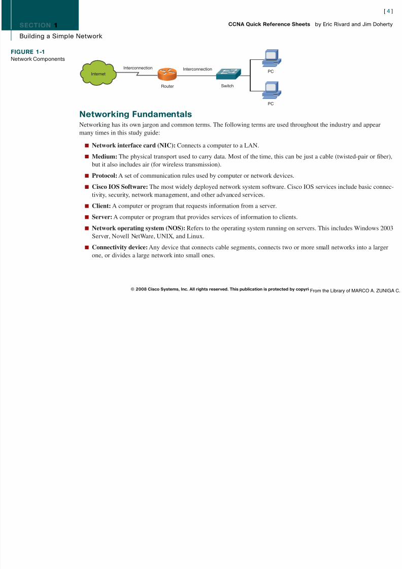
The physical layer (Layer 1) defines cabling, connection specifications, and topology.
The data link layer (Layer 2) has the following functions:
n Provides physical addressing
n Provides support for connection-oriented and connectionless services
n Provides frame sequencing and flow control
Two sublayers perform data-link functions: the MAC layer and the Logical Link Control (LLC) layer.
Figure 3-2 shows the Media Access Control (MAC) sublayer (802.3). The MAC sublayer is responsible for how data issent over the wire. The MAC address is a 48-bit address expressed as 12 hex digits.
[ 33 ]
© 2008 Cisco Systems, Inc. All rights reserved. This publication is protected by copyright. Please see page 311 for more details.
CCNA Quick Reference Sheets by Eric Rivard and Jim Doherty
FIGURE 3-1Physical and DataLink Layers
EIA/TIA-232v.35
802.2
802.3
H D L C
F r a m e
R e
l a y
E t h e r n e
t
P h y s
i c a
l
D a
t a L
i n k
From the Library of MARCO A. ZUNIGA C.
[ 34 ]

8/12/2019 59811139 CCNA Quick Reference Sheets
http://slidepdf.com/reader/full/59811139-ccna-quick-reference-sheets 34/311
SECTION 3
Understanding Ethernet
The MAC sublayer defines the following:
n Physical addressing
n Network topology
n Line discipline
n Error notification
n
Orderly delivery of framesn Optional flow control
The LLC sublayer (802.2) is responsible for identifying and encapsulating different protocol types. Two types of LLCframes exist: service access points (SAP) and Subnetwork Access Protocol (SNAP). SNAP is used to support non-802protocols. Figure 3-3 shows the LLC sublayer frame.
[ 34 ]
© 2008 Cisco Systems, Inc. All rights reserved. This publication is protected by copyright. Please see page 311 for more details.
CCNA Quick Reference Sheets by Eric Rivard and Jim Doherty
FIGURE 3-2MAC Sublayer
MAC Layer - 802.3
#Bytes 8 6 6 2 Variable 4
Ethernet IIUses "Type"Here andDoes Not Use802.2.0000.0C xx.xxxx
IEEE Assigned VendorAssigned
MAC Address
Preamble Dest Add Source Add Length Data FCS
From the Library of MARCO A. ZUNIGA C.
[ 35 ]

8/12/2019 59811139 CCNA Quick Reference Sheets
http://slidepdf.com/reader/full/59811139-ccna-quick-reference-sheets 35/311
SECTION 3
Understanding Ethernet
Role of CSMA/CD in EthernetAll stations on an Ethernet segment are connected to the same media. Therefore, all devices receive all signals. Whendevices send signals at the same time, a collision occurs. A scheme is needed to detect and compensate for collisions.
Ethernet uses a method called carrier sense multiple access collision detect (CSMA/CD) to detect collisions.
In CSMA/CD, many stations can transmit on the Ethernet media, and no station has priority over any other. Before astation transmits, it listens to the network (carrier sense) to make sure that no other station is transmitting. If no otherstation is transmitting, the station transmits across the media. If a collision occurs, the transmitting stations detect thecollision and run a backoff algorithm. The backoff algorithm computes a random time that each station waits beforeretransmitting.
[ 35 ]
© 2008 Cisco Systems, Inc. All rights reserved. This publication is protected by copyright. Please see page 311 for more details.
CCNA Quick Reference Sheets by Eric Rivard and Jim Doherty
FIGURE 3-3LLC Sublayer
802.2 (SNAP)
1
1 1
1 1 or 2
1 or 2
3 2 Variable
Variable
802.2 (SAP)Or
Dest SAPAA
Source SAPAA
Ctrl03
OUIID Type Data
DataDestSAP
SourceSAP Ctrl
MAC Layer - 802.3
Preamble Dest add Source add Length Data FCS
From the Library of MARCO A. ZUNIGA C.
[ 36 ]

8/12/2019 59811139 CCNA Quick Reference Sheets
http://slidepdf.com/reader/full/59811139-ccna-quick-reference-sheets 36/311
SECTION 3
Understanding Ethernet
Ethernet LAN TrafficThree major types of network traffic exist on a LAN:
n Unicasts: The most common type of LAN traffic. A unicast frame is a frame intended for only one host.
n Broadcasts: Intended for all hosts. Stations view broadcast frames as public service announcements. All stationsreceive and process broadcast frames.
n Multicasts: Traffic in which one transmitter tries to reach only a subset, or group, of the entire segment.
Ethernet AddressesThe Ethernet address, or MAC address, is the Layer 2 address of the network adapter of the network device. Typicallyburned into the adapter, the MAC address is usually displayed in a hexadecimal format such as 00-0d-65-ac-50-7f.
As shown in Figure 3-4, the MAC address is 48 bits and consists of the following two components:
n Organizational Unique Identifier (OUI): 24 bits. This is IEEE assigned and identifies the manufacturer ofthe card.
n Vendor-assigned: 24 bits. Uniquely identifies the Ethernet hardware.
[ 36 ]
© 2008 Cisco Systems, Inc. All rights reserved. This publication is protected by copyright. Please see page 311 for more details.
CCNA Quick Reference Sheets by Eric Rivard and Jim Doherty
FIGURE 3-4MAC Addresses OUI
24-Bits
48-bit MAC Address
Vendor
Assigned24-bits
From the Library of MARCO A. ZUNIGA C.
[ 37 ]

8/12/2019 59811139 CCNA Quick Reference Sheets
http://slidepdf.com/reader/full/59811139-ccna-quick-reference-sheets 37/311
SECTION 3
Understanding Ethernet
Connecting to an Ethernet LANThe term Ethernet encompasses several LAN implementations. Physical layer implementations vary, and all support
various cabling structures. The following four main categories of Ethernet exist:n Ethernet (DIX) and IEEE 802.3: Operate at 10 Mbps over coaxial cable, unshielded twisted-pair (UTP) cable,
or fiber. The standards are referred to as 10BASE2, 10BASE5, 10BASE-T, and 10BASE-F.
n Fast Ethernet or 100-Mbps Ethernet: Operates over UTP or fiber.
n Gigabit Ethernet: An 802.3 extension that operates over fiber and copper at 1000 Mbps, or 1 gigabit per second (Gbps).
n 10-Gigabit Ethernet: Defined in 802.3ae, runs in full-duplex mode only, over fiber.
Table 3-1 compares cable and connecter specifications. Fast Ethernet and Gigabit Ethernet require UTP Category 5e (orhigher) or fiber cabling.
TABLE 3-1 Ethernet Media and Connection Requirements10BASE-T 100BASE-TX 100BASE-FX 1000BASE-CX 1000BASE-T 1000BASE-SX 1000BASE-LX
Media EIA/TIA Cat EIA/TIA Cat 5 62.5/125 micro- STP EIA/TIA Cat 5 62.5/50 micro- 9-micron single-3, 4, 5 UTP UTP 2-pair multimode fiber UTP 4-pair multimode fiber mode fiber2-pair
Maximum 100 m 100 m 400 m 25 m 100 m 275 m 3–10 kmSegmentLength
Connector ISO 8877 ISO 8877 Duplex media ISO 8877 ISO 8877 — —(RJ-45) (RJ-45) interface (RJ-45) (RJ-45)
connector(MIC) ST
[ 37 ]
© 2008 Cisco Systems, Inc. All rights reserved. This publication is protected by copyright. Please see page 311 for more details.
CCNA Quick Reference Sheets by Eric Rivard and Jim Doherty
From the Library of MARCO A. ZUNIGA C.
[ 38 ]

8/12/2019 59811139 CCNA Quick Reference Sheets
http://slidepdf.com/reader/full/59811139-ccna-quick-reference-sheets 38/311
SECTION 3
Understanding Ethernet
A Gigabit Interface Converter (GBIC) is a hot-swappable I/O device that plugs into a Cisco Gigabit Ethernet port. GBICsare interchangeable, and they allow you to deploy different types of 1000BASE-X technology without having to changethe physical interface of the switch. GBICs support UTP and fiber media.
Network Media TypesNetwork media refers to the physical path that signals take across a network. The most common types of media are asfollows:
n Twisted-pair cable: Used for telephony and most Ethernet networks. Each pair makes up a circuit that can transmitsignals. The pairs are twisted to prevent interference (crosstalk). The two categories of twisted-pair cables areunshielded twisted-pair (UTP) and shielded twisted-pair (STP), defined as follows:
n UTP cable: Usually connected to equipment with an RJ-45 connector. UTP has a small diameter that can be anadvantage when space for cabling is at a minimum. It is prone to electrical noise and interference because of thelack of shielding. Seven categories of UTP cable exist: CAT 1, CAT 2, CAT 3, CAT 4, CAT 5, CAT 5e, andCAT 6.
[ 38 ]
© 2008 Cisco Systems, Inc. All rights reserved. This publication is protected by copyright. Please see page 311 for more details.
CCNA Quick Reference Sheets by Eric Rivard and Jim Doherty
FIGURE 3-5UTP
Outer Jacket
Color-Coded PlasticInsulation
Twisted Pair
Unshielded Twisted Pairs
From the Library of MARCO A. ZUNIGA C.
[ 39 ]

8/12/2019 59811139 CCNA Quick Reference Sheets
http://slidepdf.com/reader/full/59811139-ccna-quick-reference-sheets 39/311
SECTION 3
Understanding Ethernet
n STP cable: Provides much better protection against electrical noise and interference than UTP but is thicker andmore expensive. The cable speed and maximum length are the same as for UTP (speed is 10 to 100 Mbps, andmaximum length is 100 m).
n Fiber-optic cable: Allows the transmission of light signals. This offers a large jump in bandwidth over other typesof cables (1 Gbps or greater). The two types of fiber-optic cables are multimode and single-mode, defined asfollows:
n Multimode: With this type of fiber, several modes (or wavelengths) propagate down the fiber, each taking aslightly different path. Multimode fiber is used primarily in systems with short transmission distances (less than2 km).
n Single-mode: This type of fiber has only one mode in which light can propagate. Single-mode fiber is typicallyused for long-distance and high-bandwidth applications.
UTP ImplementationAn RJ-45 connector is use with UTP cabling. Figure 3-7 shows an RJ-45 connector and its pin connections.
[ ]
© 2008 Cisco Systems, Inc. All rights reserved. This publication is protected by copyright. Please see page 311 for more details.
CCNA Quick Reference Sheets by Eric Rivard and Jim Doherty
FIGURE 3-6STP Outer
JacketOverallShield
PairShields Twisted Pair
Color-CodedPlastic
Insulation
Shielded Twisted Pairs
From the Library of MARCO A. ZUNIGA C.
[ 40 ]

8/12/2019 59811139 CCNA Quick Reference Sheets
http://slidepdf.com/reader/full/59811139-ccna-quick-reference-sheets 40/311
SECTION 3
Understanding Ethernet
The two types of connections are straight-through and crossover. Straight-through cables are typically used to connectdifferent devices (data terminal equipment [DTE] to data communications equipment [DCE]), such as switch-to-routerconnections. Figure 3-8 shows the pins for a straight-through cable.
[ ]
© 2008 Cisco Systems, Inc. All rights reserved. This publication is protected by copyright. Please see page 311 for more details.
CCNA Quick Reference Sheets by Eric Rivard and Jim Doherty
FIGURE 3-7RJ-45 Connector
Bits:
Bits:
Bits:
Bits:
Class A:
Class B:
Class C:
Class D:
1 8 9 16 17 24 25 32
Range (224-239)
1110 MMMM MulticastGroup
MulticastGroup
MulticastGroup
1 8 9 16 17 24 25 32
Range (192-223)
110 NNNNN Network Network Host
1 8 9 16 17 24 25 32
Range (128-191)
10 NNNNNN Network Host Host
1 8 9 16 17 24 25 32
Range (1-126)
0NNNNNNN Host Host Host
FIGURE 3-8Straight-ThroughWiring
Cable 10 BASE-TX100BASE-T Straight-Through
Pin Label Pin Label
Hub/Switch Server/Router
1 RD+2 RD–3 TD+
4 NC5 NC6 TD–7 NC8 NC
1 TD+2 TD–3 RD+
4 NC5 NC6 RD–7 NC8 NC
From the Library of MARCO A. ZUNIGA C.
[ 41 ]

8/12/2019 59811139 CCNA Quick Reference Sheets
http://slidepdf.com/reader/full/59811139-ccna-quick-reference-sheets 41/311
SECTION 3
Understanding Ethernet
Crossover cables are typically used to connect similar devices, such as switch-to-switch connections. The primary excep-tion to this rule is switch-to-hub connections, which use a crossover cable. Figure 3-9 shows the pins for a crossover cable.
© 2008 Cisco Systems, Inc. All rights reserved. This publication is protected by copyright. Please see page 311 for more details.
CCNA Quick Reference Sheets by Eric Rivard and Jim Doherty
FIGURE 3-9Crossover Wiring
Cable 10 BASE-T/ 100BASE-T Crossover
Hub/Switch
1 RD+2 RD–3 TD+4 NC5 NC6 TD–7 NC8 NC
Pin Label Pin Label
Hub/Switch
1 RD+2 RD–3 TD+4 NC5 NC6 TD–7 NC8 NC
From the Library of MARCO A. ZUNIGA C.

8/12/2019 59811139 CCNA Quick Reference Sheets
http://slidepdf.com/reader/full/59811139-ccna-quick-reference-sheets 42/311
[ 43 ]
8/12/2019 59811139 CCNA Quick Reference Sheets
http://slidepdf.com/reader/full/59811139-ccna-quick-reference-sheets 43/311
SECTION 4
LAN Network Topologies
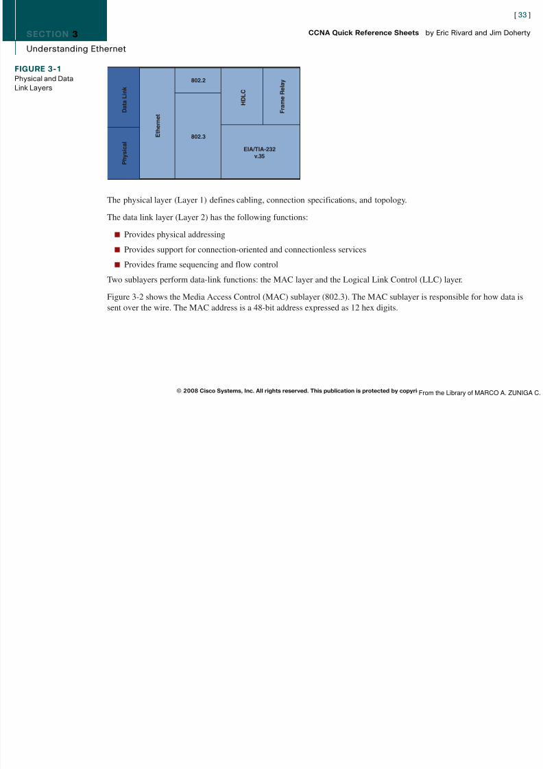
Figure 4-2 shows a ring topology. In a ring topology, a frame travels in a logical order around the ring, going from oneend station to the next. If an end station wants to send data, it is added to the frame. The frame continues around the ring,and the data is removed at the intended destination. The frame, however, continues. In a single ring, data travels in a
single direction. In a dual ring, each ring sends data in a different direction. Two rings create redundancy, or fault toler-ance, which means that if one ring fails, the system can still operate. If parts of both rings fail, a “wrap” (a connectionbetween the two rings) can heal the fault.
Star topologies are the most common physical topology in Ethernet LANs. As shown in Figure 4-3, stars have a centralconnection (hub, switch, or router) where all end devices meet. Stars cost more than other topologies but are more faulttolerant because a cable failure usually affects only one end device, or host. The disadvantage of a star is that if thecentral device fails, the entire system fails.
In an extended star, the central networking device connects to other networking devices, which then connect to endstations. Figure 4-4 shows an extended star topology.
In a full-mesh topology, all devices are connected to all other devices. Great redundancy exists on full-mesh networks, butfor networks with more than a few devices, it becomes overly expensive and complicated. Partial-mesh topologies, whichhave at least one device with multiple connections, provide good redundancy without the expense of full meshes. Figure4-5 shows a full-mesh topology.
© 2008 Cisco Systems, Inc. All rights reserved. This publication is protected by copyright. Please see page 311 for more details.
CCNA Quick Reference Sheets by Eric Rivard and Jim Doherty
FIGURE 4-1
Bus Topology
FIGURE 4-2
Ring Topology
FIGURE 4-3
Star Topology
FIGURE 4-4Extended StarTopology
From the Library of MARCO A. ZUNIGA C.
[ 44 ]

8/12/2019 59811139 CCNA Quick Reference Sheets
http://slidepdf.com/reader/full/59811139-ccna-quick-reference-sheets 44/311
SECTION 4
LAN Network Topologies
The last type of network topology is one that does not require the use of traditional cable connections, such as wirelessnetworks. Wireless communications use radio frequencies (RF) or infrared (IR) waves to transmit data over a LAN.Wireless adapters must be installed on a laptop (wireless NIC) to communicate with the network. Wireless gives network designers many new options, because no physical medium is required to connect end stations (which is great for installa-tion in old buildings or offices with inadequate space for cabling). See Figure 4-6.
© 2008 Cisco Systems, Inc. All rights reserved. This publication is protected by copyright. Please see page 311 for more details.
CCNA Quick Reference Sheets by Eric Rivard and Jim Doherty
FIGURE 4-5Full-Mesh Topology
FIGURE 4-6Wireless Topology
From the Library of MARCO A. ZUNIGA C.

8/12/2019 59811139 CCNA Quick Reference Sheets
http://slidepdf.com/reader/full/59811139-ccna-quick-reference-sheets 45/311
[ 46 ]

8/12/2019 59811139 CCNA Quick Reference Sheets
http://slidepdf.com/reader/full/59811139-ccna-quick-reference-sheets 46/311
SECTION 4
LAN Network Topologies
disabling the network but do not create additional collision domains. Hubs provide no filtering and forward all traffic outall ports regardless of where they are destined.
Switches are Layer 2 devices that amplify a signal and use Layer 2 information to route traffic.
Collisions and Collision DomainsIn traditional Ethernet segments, all devices compete for the same bandwidth. The network segments that share the samebandwidth are called collision domains. All devices on the same network segment receive all signals sent on the segment.Collisions occur when two or more end stations “listen” for traffic on the segment, hear nothing, and then transmit at thesame time. The simultaneous transmissions collide, and all are destroyed and must be resent. Each end station resendsafter a random time (called a backoff algorithm). As the number of end stations increases, collisions increase to the pointwhere the system is virtually unusable because collisions are constantly occurring. Collisions are by-products of CSMA/CD. As networks grow, the chances that devices transmit at the same time increase, resulting in more collisions.
Repeaters and hubs amplify a signal and increase segment distance limitations; however, they cannot decrease collisions.
A collision domain is a group of devices connected to the same network segment such that if two devices access themedium at the same time, a collision results.
Solving Network Challenges with Switched LANTechnologyAs networks grow and evolve, network congestion increases. The most common causes of network congestion are asfollows:
n Increases in PC speed and performance
n Increases in network data
n Bandwidth-intensive applications
© 2008 Cisco Systems, Inc. All rights reserved. This publication is protected by copyright. Please see page 311 for more details.
CCNA Quick Reference Sheets by Eric Rivard and Jim Doherty
From the Library of MARCO A. ZUNIGA C.
[ 47 ]

8/12/2019 59811139 CCNA Quick Reference Sheets
http://slidepdf.com/reader/full/59811139-ccna-quick-reference-sheets 47/311
SECTION 4
LAN Network Topologies
BridgesBridges were used as an early solution for network congestion. Bridges used the concept of segmentation to allow more
end stations to be added to a LAN (called scaling). Segmentation is a method of breaking up collision domains. Bridgesare more intelligent than hubs and can forward or block traffic based on the data frame’s destination address (whereashubs just send the frame to every port and end station). Segmentation is shown in Figure 4-7.
SwitchesLayer 2 switches are really just high-speed, multiport, very smart bridges. Unlike bridges that process frames using soft-ware, switches process frames in hardware through the use of application-specific integrated circuits (ASICs). Switches
also have the following features:n High-speed backplane: A circuit board that allows the switch to monitor multiple conversations, which increases
the network’s overall speed.
n Data buffering: A buffer is memory storage. This function allows the switch to store frames and forward them tothe correct port.
n Higher port density: Port density is the number of ports available on a single device. A switch can have hundredsof ports.
© 2008 Cisco Systems, Inc. All rights reserved. This publication is protected by copyright. Please see page 311 for more details.
CCNA Quick Reference Sheets by Eric Rivard and Jim Doherty
FIGURE 4-7Segmenting aNetwork ThroughBridges
Bridge
Only Data Frames Intended forSegment A Are Allowed Throughfrom Segment B.
Collision Domain A Collision Domain B
From the Library of MARCO A. ZUNIGA C.
[ 48 ]

8/12/2019 59811139 CCNA Quick Reference Sheets
http://slidepdf.com/reader/full/59811139-ccna-quick-reference-sheets 48/311
SECTION 4
LAN Network Topologies
n High port speeds: Switches can support a mixture of port speeds from 10 Mbps to 10 Gbps.
n Lower latency: Latency is the measure of the time it takes an incoming frame to come back out of a switch.
n Virtual LANs (VLAN): Switches can logically segment networks into separate broadcast domains .All these features (particularly port density) allow microsegmentation, which means that each end station has a dedicatedswitch port. This eliminates collisions, because each collision domain has only a single end station. Although thesefeatures can reduce some network congestion, faster PCs can flood a network with traffic. Broadcasts and multicasts alsocontribute to network congestion.
Switch Frame Transmission ModesThe following three primary frame switching modes exist:
n Cut-through: The switch checks the destination address and immediately begins forwarding the frame. This candecrease latency but can also transmit frames containing errors.
n Store and forward: The switch waits to receive the entire frame before forwarding. The entire frame is read, and acyclic redundancy check (CRC) is performed. If the CRC is bad, the frame is discarded. Latency increases as a func-tion of frame length.
n Fragment-free (modified cut-through): The switch reads the first 64 bytes before forwarding the frame. Theminimum number of bytes necessary to detect and filter out collision frames is 64 bytes.
How Switches Segment the Ethernet Network Ethernet switches perform three major functions in segmenting a network: forwarding, filtering, and flooding.
Switches perform these functions by the following methods:
n MAC address learning: Switches learn the MAC addresses of devices attached to each of their ports. Theseaddresses are stored in a MAC database.
© 2008 Cisco Systems, Inc. All rights reserved. This publication is protected by copyright. Please see page 311 for more details.
CCNA Quick Reference Sheets by Eric Rivard and Jim Doherty
From the Library of MARCO A. ZUNIGA C.
[ 49 ]

8/12/2019 59811139 CCNA Quick Reference Sheets
http://slidepdf.com/reader/full/59811139-ccna-quick-reference-sheets 49/311
SECTION 4
LAN Network Topologies
n Forwarding and filtering: Switches determine which port a frame must be sent out to reach its destination. If theaddress is known, the frame is sent only on that port. If it’s unknown, the frame is flooded to all ports except the onefrom which it originated.
n Flooding: Switches flood all unknown frames, broadcasts, and multicasts to all ports on the switch except the onefrom which it originated.
Switches in ActionA switch uses its MAC address table when forwarding frames to devices. When a switch is first powered on, it has anempty MAC address table. With an empty MAC address table, the switch must learn the MAC addresses of attacheddevices. This learning process is outlined below using Figure 4-8:
Step 1.Initially, the switch MAC address table is empty.
Step 2. Station A with the MAC address sends a frame to station C. When the switch receives this frame, it does thefollowing:
n Because the MAC table is empty, the switch must flood the frame to all other ports (except E0, the frameorigin).
n The switch notes the source address of the originating device and associates it with port E0 in its MACaddress table entry.
Step 3. The switch continues to learn addresses in this manner, continually updating the table. As the MAC tablebecomes more complete, the switching becomes more efficient, because frames are forwarded to specificports rather than being flooded out all ports.
© 2008 Cisco Systems, Inc. All rights reserved. This publication is protected by copyright. Please see page 311 for more details.
CCNA Quick Reference Sheets by Eric Rivard and Jim Doherty
From the Library of MARCO A. ZUNIGA C.
[ 50 ]

8/12/2019 59811139 CCNA Quick Reference Sheets
http://slidepdf.com/reader/full/59811139-ccna-quick-reference-sheets 50/311
SECTION 4
LAN Network Topologies
© 2008 Cisco Systems, Inc. All rights reserved. This publication is protected by copyright. Please see page 311 for more details.
CCNA Quick Reference Sheets by Eric Rivard and Jim Doherty
FIGURE 4-8Frame Forwardingby a Switch
MAC Address Table
E0: 0260.8c01.1111
E3: 0260.8c01.4444
E0 E1
E2 E3
0260.8c01.1111
0260.8c01.3333
0260.8c01.2222
0260.8c01.4444
A
B
C
D
From the Library of MARCO A. ZUNIGA C.
[ 51 ]

8/12/2019 59811139 CCNA Quick Reference Sheets
http://slidepdf.com/reader/full/59811139-ccna-quick-reference-sheets 51/311
SECTION 5
Operating Cisco IOS
Section 5
Operating Cisco IOSCisco IOS enables network services in switches and routers. It provides the following features:
n Carries network protocols and functions
n Connectivity
n Security
n Scalability
n Reliability
The Cisco IOS command-line interface (CLI) can be accessed through a console connection, modem connection, orTelnet/SSH sessions. These connections are called EXEC sessions.
Cisco Device StartupWhen a Cisco device starts up, it goes through the following steps:
Step 1. Completes power-on self test (POST)
Step 2. Finds and loads Cisco IOS Software image
Step 3. Finds and applies device configuration
© 2008 Cisco Systems, Inc. All rights reserved. This publication is protected by copyright. Please see page 311 for more details.
CCNA Quick Reference Sheets by Eric Rivard and Jim Doherty
From the Library of MARCO A. ZUNIGA C.
[ 52 ]

8/12/2019 59811139 CCNA Quick Reference Sheets
http://slidepdf.com/reader/full/59811139-ccna-quick-reference-sheets 52/311
SECTION 5
Operating Cisco IOS
External Configuration SourcesAn IOS device can be configured from any of the following external sources:
n Console terminal
n Remote terminal (aux port)
n Telnet
n TFTP
n CiscoWorks
n SSH
Only a console connection or remote terminal connection can be used to initially configure a router or switch.
Console ConnectionTo establish a connection through a console port, you need a rollover cable to connect a console port to a PC. To set upthe connection, follow these steps:
Step 1. Cable the device using a rollover cable. You might need an adapter for the PC.
Step 2. Configure the terminal emulation application with the following COM port settings: 9600 bps, 8 data bits, noparity, 1 stop bit, and no flow control.
© 2008 Cisco Systems, Inc. All rights reserved. This publication is protected by copyright. Please see page 311 for more details.
CCNA Quick Reference Sheets by Eric Rivard and Jim Doherty
From the Library of MARCO A. ZUNIGA C.
[ 53 ]

8/12/2019 59811139 CCNA Quick Reference Sheets
http://slidepdf.com/reader/full/59811139-ccna-quick-reference-sheets 53/311
SECTION 5
Operating Cisco IOS
Cisco IOS Software Command-Line InterfaceFunctionsCisco IOS uses a hierarchy of commands in its command-mode structure. For security, Cisco IOS separates EXECsessions into these two access levels:
n User EXEC mode (user mode)
n Privileged EXEC mode (enable mode)
User EXEC mode is the first mode you enter when you log in to the IOS. This mode is limited and is mostly used to viewstatistics. You cannot change a router’s configuration in this mode. By default, the greater-than sign (>) indicates that youare in user mode. This is how the router prompt looks in user mode:
Router>
In privileged EXEC mode, you can view and change the configuration in a router; you have access to all the router’scommands and the powerful debug commands.
To enter privileged mode, enter the enable command while in user mode. By default, the pound symbol (#) indicates thatyou are in privileged mode. This mode is usually protected with a password. Here is an example of how to enter privi-leged mode. You also see the output of the prompt:
Router> enable
Password:
Router#
Keyboard Help in the CLISeveral commands built into IOS provide help when you enter configuration commands:
n ? displays a list of commonly used commands.
© 2008 Cisco Systems, Inc. All rights reserved. This publication is protected by copyright. Please see page 311 for more details.
CCNA Quick Reference Sheets by Eric Rivard and Jim Doherty
From the Library of MARCO A. ZUNIGA C.
[ 54 ]

8/12/2019 59811139 CCNA Quick Reference Sheets
http://slidepdf.com/reader/full/59811139-ccna-quick-reference-sheets 54/311
SECTION 5
Operating Cisco IOS
n -More appears at the bottom of the screen when additional information exists. Display the next available screen bypressing the spacebar. Display the next line by pressing Enter. Press any other key to return to the user-mode prompt.
n s? lists all commands that start with s .
n show ? lists all variants of the show command.
Enhanced Editing CommandsEnabled by default, enhanced editing commands allow shortcuts to speed the editing process. Table 5-1 shows theenhanced editing commands available in Cisco IOS Software.
TABLE 5-1 Enhanced Editing Commands
Command ActionCtrl-A Moves the cursor to the beginning of the line
Ctrl-E Moves the cursor to the end of the line
Esc-B Moves the cursor back one word
Esc-F Moves the cursor forward one word
Ctrl-B Moves the cursor back one character
Ctrl-F Moves the cursor forward one character
Ctrl-D Deletes a single characterBackspace Removes one character to the left of the cursor
Ctrl-R Redisplays a line
Ctrl-U Erases from the cursor to the beginning of the line
© 2008 Cisco Systems, Inc. All rights reserved. This publication is protected by copyright. Please see page 311 for more details.
CCNA Quick Reference Sheets by Eric Rivard and Jim Doherty
continues
From the Library of MARCO A. ZUNIGA C.

8/12/2019 59811139 CCNA Quick Reference Sheets
http://slidepdf.com/reader/full/59811139-ccna-quick-reference-sheets 55/311
[ 56 ]

8/12/2019 59811139 CCNA Quick Reference Sheets
http://slidepdf.com/reader/full/59811139-ccna-quick-reference-sheets 56/311
SECTION 5
Operating Cisco IOS
TABLE 5-2 Console Error MessagesError Message Meaning How to Get Help
% Ambiguous command: "show con" Not enough characters were entered Reenter the command, fol lowed by ato define a specific command. question mark (?), with no space
between the command and thequestion mark.
% Incomplete command. Keywords or values are missing. Reenter the command, followed by aquestion mark (?), with a space betweenthe command and the question mark.
% Invalid input detected at '̂ ' marker. The command was entered incorrectly. Enter a question mark (?) toThe caret (^) marks the point of display all the commands orthe error. parameters that are available in
this mode.
© 2008 Cisco Systems, Inc. All rights reserved. This publication is protected by copyright. Please see page 311 for more details.
CCNA Quick Reference Sheets by Eric Rivard and Jim Doherty
From the Library of MARCO A. ZUNIGA C.
[ 57 ]

8/12/2019 59811139 CCNA Quick Reference Sheets
http://slidepdf.com/reader/full/59811139-ccna-quick-reference-sheets 57/311
SECTION 6
Configuring a Cisco Switch
Section 6
Configuring a Cisco SwitchStarting a SwitchWhen a Catalyst switch is started for the first time, a default configuration is loaded. Three main operations areperformed during normal startup:
1. A power-on self test (POST) checks the hardware.
2. A startup routine initiates the operating system.
3. Software configuration settings are loaded.
Initial startup procedure:
Step 1. Before you start the switch, verify the following:
n All network cable connections are secure.
n A terminal is connected to the console port.
n A terminal application is selected.
Step 2. Attach the switch to the power source to start the switch (there is no on/off switch).Step 3. Observe the boot sequence.
© 2008 Cisco Systems, Inc. All rights reserved. This publication is protected by copyright. Please see page 311 for more details.
CCNA Quick Reference Sheets by Eric Rivard and Jim Doherty
From the Library of MARCO A. ZUNIGA C.
[ 58 ]

8/12/2019 59811139 CCNA Quick Reference Sheets
http://slidepdf.com/reader/full/59811139-ccna-quick-reference-sheets 58/311
SECTION 6
Configuring a Cisco Switch
Switch LED IndicatorsFigure 6-1 shows the LEDs on the front panel of the switch. These LEDs provide information on switch status during
startup, normal operation, and fault conditions. Pressing the Mode button toggles through the following LED displaymodes:
n Port status
n Bandwidth utilization
n Full-duplex support
Table 6-1 details switch LED status indications for the Catalyst 2960.
© 2008 Cisco Systems, Inc. All rights reserved. This publication is protected by copyright. Please see page 311 for more details.
CCNA Quick Reference Sheets by Eric Rivard and Jim Doherty
FIGURE 6-1Catalyst 2960 LEDs
Port Status LEDs
Port Mode LEDs
System LED
Mode Button
From the Library of MARCO A. ZUNIGA C.
[ 59 ]

8/12/2019 59811139 CCNA Quick Reference Sheets
http://slidepdf.com/reader/full/59811139-ccna-quick-reference-sheets 59/311
SECTION 6
Configuring a Cisco Switch
TABLE 6-1 Catalyst 2960 LEDsLED Status
System LED Green: System powered and operational
Amber: System malfunction; one or more POST errors
Redundant power supply (RPS) Green: RPS operationalFlashing green: RPS connected but is powering another deviceAmber: RPS installed but not operationalFlashing amber: The internal power supply and RPS have power and are poweringthe switch
Port status (STAT) Green: Link presentFlashing green: Link present with traffic activityAlternating green and amber: Link fault
Amber: Port not forwardingBandwidth utilization (UTL) Green: Bandwidth utilization displayed over the amber LED on a
logarithmic scaleAmber: Maximum backplane utilization since the switch was powered onGreen and amber: Depends on the model
Full-duplex (FDUP) Green: Ports are configured in full-duplex modeOff: Ports are half-duplex
Configuring a Switch from the Command LineThe following two configuration modes are available:
n Global configuration: Configures global parameters on a switch, such as IP address and host name
n Interface configuration: Configures parameters specific to a switch port
© 2008 Cisco Systems, Inc. All rights reserved. This publication is protected by copyright. Please see page 311 for more details.
CCNA Quick Reference Sheets by Eric Rivard and Jim Doherty
From the Library of MARCO A. ZUNIGA C.
[ 60 ]

8/12/2019 59811139 CCNA Quick Reference Sheets
http://slidepdf.com/reader/full/59811139-ccna-quick-reference-sheets 60/311
SECTION 6
Configuring a Cisco Switch
The IOS command to enter global configuration mode is configure terminal .
The IOS command to enter interface configuration mode is interface interface-id .
To enter interface mode, you first need to be in global configuration mode. The interface-id parameter identifies the typeand number of the interface you want to configure, as follows:
switch(config)# interface g0
switch(config-if)#
Configuring a Host NameTo give the switch a host name or identify it, use the hostname privileged IOS command, as follows:
switch(config)#hostname Admin-SW Admin-Sw(config)#
Configuring the Switch IP Address and Default GatewayTo assign an IP address on a Catalyst 2960 switch, follow these steps:
Step 1. Enter the VLAN 1 interface. This is a logical interface used for management.
Step 2. Assign the IP address and subnet masks.
Step 3. Enable the interface by issuing the no shutdown command.
The following example shows the necessary command syntax for all three steps:
Admin-Sw(config)# interface vlan1
Admin-Sw(config-if)# ip address 192.168.0.10 255.255.255.0
Admin-Sw(config-if)# no shutdown
© 2008 Cisco Systems, Inc. All rights reserved. This publication is protected by copyright. Please see page 311 for more details.
CCNA Quick Reference Sheets by Eric Rivard and Jim Doherty
From the Library of MARCO A. ZUNIGA C.
[ 61 ]

8/12/2019 59811139 CCNA Quick Reference Sheets
http://slidepdf.com/reader/full/59811139-ccna-quick-reference-sheets 61/311
SECTION 6
Configuring a Cisco Switch
To configure the default gateway, use the ip default-gateway ip-address global configuration command, as follows:
Switch(config)# ip default-gateway 192.168.0.1
Showing Switch StatusTo display the status of a switch, use one of the following commands:
n show running-configuration displays the currently active configuration in memory, including any changes made inthe session that have not yet been saved.
n show startup-config displays the last saved configuration.
n show version displays information about the system hardware and software.
n show interfaces displays information on connections and ports that connect with other devices.
Managing MAC AddressesMAC address tables contain the following three types of addresses:
n Dynamic addresses are learned by the switch and then are dropped when they are not in use.
n Permanent and static addresses are assigned by an administrator.
MAC Address ConfigurationThe mac-address-table static global configuration command associates a MAC address with a particular switched portinterface. The syntax for the mac-address-table command is as follows:
mac-address-table static mac-address vlan vlan-id interface interface-id
You verify the MAC address table settings using the show mac-address-table command.
© 2008 Cisco Systems, Inc. All rights reserved. This publication is protected by copyright. Please see page 311 for more details.
CCNA Quick Reference Sheets by Eric Rivard and Jim Doherty
NOTESome switches can beconfigured to dynami-cally learn MACaddresses associated witha port and automaticallycreate a static entry for
the learned MAC addressin the MAC addresstable. This type of address is called asticky address.
From the Library of MARCO A. ZUNIGA C.
[ 62 ]
8/12/2019 59811139 CCNA Quick Reference Sheets
http://slidepdf.com/reader/full/59811139-ccna-quick-reference-sheets 62/311
SECTION 6
Configuring a Cisco Switch
Understanding Switch SecuritySecuring a switch includes physical, environmental, and access security. Physical and environmental security is outlined
in Chapter 2.Some basic security suggestions for network devices are as follows:
n Use complex passwords for all devices.
n Limit Telnet access using access lists.
n Use SSH instead of Telnet.
n Physically secure access to the switch.
nUse banners to warn against unauthorized access.
n Set up and monitor syslog.
n Configure port security.
n Disable unused ports.
Configuring Password SecurityThe CLI is used to configure password security. You configure passwords to secure access to the switch. You can config-
ure the following passwords using the CLI:
n Console: Password that accesses the console port
n Telnet: Password that accesses the virtual terminal ports on the switch
n Enable: Nonencrypted password that accesses privileged EXEC mode
n Secret: Encrypted password that accesses privileged EXEC mode
© 2008 Cisco Systems, Inc. All rights reserved. This publication is protected by copyright. Please see page 311 for more details.
CCNA Quick Reference Sheets by Eric Rivard and Jim Doherty
From the Library of MARCO A. ZUNIGA C.
[ 63 ]

8/12/2019 59811139 CCNA Quick Reference Sheets
http://slidepdf.com/reader/full/59811139-ccna-quick-reference-sheets 63/311
SECTION 6
Configuring a Cisco Switch
If the enable password and the enable secret password are both set on the switch, the enable secret password will overridethe enable password.
The console, Telnet, and enable passwords are displayed unencrypted. To encrypt them, use theservice password-
encryption global command, as follows:
Cat2960(config)# service password-encryption
Configuring Console PasswordTo configure the console password, enter the following:
Cat2960(config)# line console 0
Cat2960(config-line)# login
Cat2960(config-line)# password CCNA
Configuring Telnet PasswordTo configure the Telnet password, enter the following:
Cat2960(config)# line vty 0 15
Cat2960(config-line)# login
Cat2960(config-line)# password CCNA
Configuring Enable and Secret Passwords
To configure enable and secret passwords, enter the following:Cat2960(config)# enable password CiscoCat2960(config)# enable secret cisco
© 2008 Cisco Systems, Inc. All rights reserved. This publication is protected by copyright. Please see page 311 for more details.
CCNA Quick Reference Sheets by Eric Rivard and Jim Doherty
From the Library of MARCO A. ZUNIGA C.
[ 64 ]

8/12/2019 59811139 CCNA Quick Reference Sheets
http://slidepdf.com/reader/full/59811139-ccna-quick-reference-sheets 64/311
SECTION 6
Configuring a Cisco Switch
Configuring Login Banner and MOTDThe login banner is displayed before the username and password login prompts on a Catalyst switch. The login banner isconfigured using the banner login global command, as follows:
Cat2960# config t
Enter configuration commands, one per line. End with CNTL/Z.
Cat2960(config)# banner login #
Enter TEXT message. End with the character ‘#’.
Notice! Only Authorized Personnel Are Allowed to Access This Device
#
The message of the day (MOTD) is displayed before the login banner. It is displayed to anyone who connects to theCisco IOS device through Telnet, console port, or auxiliary port. Use the banner motd # text # global configuration
command to configure the MOTD. In the previous command, the # character is a delimiting character and can be anycharacter.
Cat2960(config)# banner motd # <ENTER>
Enter TEXT message. End with the character ‘#’.
Warning only authorized users many access this switch. <ENTER>#
Cat2960(config)#
SSH AccessCisco recommends using SSH to encrypt communication between the Cisco device and the host. Telnet is unsecure, and allcommunication between the Cisco device and the host is sent in clear text. Use the following steps to configure SSH access:
Step 1. Create a local username and password on the device.
Step 2. Assign a domain name to the device.
© 2008 Cisco Systems, Inc. All rights reserved. This publication is protected by copyright. Please see page 311 for more details.
CCNA Quick Reference Sheets by Eric Rivard and Jim Doherty
From the Library of MARCO A. ZUNIGA C.
[ 65 ]
k f h b d d h

8/12/2019 59811139 CCNA Quick Reference Sheets
http://slidepdf.com/reader/full/59811139-ccna-quick-reference-sheets 65/311
SECTION 6
Configuring a Cisco Switch
Step 3. Generate a security key.
Step 4. Enable SSH.
Step 5. Configure vty ports to authenticate using SSH.The following commands demonstrate how to configure SSH access:
switch(config)# username eric password 0 ciscopress
switch(config)# ip domain-name cisco.com
switch(config)# crypto key generate rsa
The name for the keys will be: switch.cisco.comChoose the size of the key modulus in the range of 360 to 2048 for your
General Purpose Keys. Choosing a key modulus greater than 512 may take
a few minutes.
How many bits in the modulus [512]:
% Generating 512 bit RSA keys ...[OK]
switch(config)# ip ssh ver 2
switch(config)# line vty 0 15switch(config-line)# login localswitch(config-line)# transport input telnet ssh
Securing vty Access
By default, any IP address can connect to a vty line. Recommended practice dictates restricting access to vty lines by IPaddress. This is done through standard access lists.
Standard access lists allow you to permit or deny traffic based on the source IP address. To restrict access to vty lines,you would create a standard access list that permits each authorized IP address to connect to vty and apply the access listto the vty lines.
© 2008 Cisco Systems, Inc. All rights reserved. This publication is protected by copyright. Please see page 311 for more details.
CCNA Quick Reference Sheets by Eric Rivard and Jim Doherty
From the Library of MARCO A. ZUNIGA C.
[ 66 ]
CCNA Q i k R f Sh b E i Ri d d Ji D h

8/12/2019 59811139 CCNA Quick Reference Sheets
http://slidepdf.com/reader/full/59811139-ccna-quick-reference-sheets 66/311
SECTION 6
Configuring a Cisco Switch
At the end of each access list is an implicit deny any statement. So, if a host is not specifically permitted, it will bedenied.
Wildcard MasksWildcard masks define the subset of the 32 bits in the IP address that must be matched.
Wildcards are used with access lists to specify a host, network, or part of a network. Wildcard masks work exactly theopposite of subnet masks.
In wildcard masks, when 0s are present, the octet address must match. Mask bits with a binary value of 1 are wildcards.For example, if you have an IP address 172.16.0.0 with a wildcard mask of 0.0.255.255, the first two portions of the IPaddress must match 172.16, but the last two octets can be in the range of 1 to 255.
Configuring and Applying vty Access ListsThe command syntax to create a standard IP access list is as follows:
access-list access-list-number {permit | deny } source-address
[ wildcard-mask ]
The access-list-number parameter is a number from 1 to 99 or 1300 to 1999.
The command syntax to apply an access list to an interface is as follows:
access-class access-list-number { in | out }The following commands create access list number 10, permitting Telnet access to the vty lines from IP network 192.168.10.0/24:
SwitchA(config)# access list 10 permit ip 192.168.10.0 0.0.0.255
SwitchA(config)# line vty 0 15
SwitchA(config-if)# access-class 10 in This applies the access list to telnet ports
© 2008 Cisco Systems, Inc. All rights reserved. This publication is protected by copyright. Please see page 311 for more details.
CCNA Quick Reference Sheets by Eric Rivard and Jim Doherty
From the Library of MARCO A. ZUNIGA C.
6
[ 67 ]
CCNA Q i k R f Sh t b E i Ri d d Ji D h t

8/12/2019 59811139 CCNA Quick Reference Sheets
http://slidepdf.com/reader/full/59811139-ccna-quick-reference-sheets 67/311
SECTION 6
Configuring a Cisco Switch
Implementing and Verifying Port SecurityPort security limits the number of MAC address allowed per port and can also limit which MAC addresses are allowed.Allowed MAC addresses can be manually configured or dynamically learned by the switch. The interface command toconfigure port security is as follows:
switchport port-security [ mac-address mac-address | mac-address sticky [ mac-address ] | maximum value |
violation {restrict | shutdown }
n switchport port-security mac-address mac-address : Manually configures the port to use a specific MAC address.
n switchport port-security mac-address sticky: Configures the switch to dynamically learn the MAC address of thedevice attached to the port.
n switchport port-security maximum value : Configures the maximum number of MAC addresses allowed on the
port. The default value is 1.n switchport port-security violation {restrict | shutdown }: Configures the action to be taken when the maximum
number of MAC addresses is reached and when MAC addresses not associated with the port try to access the port.The restrict keyword tells the switch to restrict access to learned MAC addresses that are above the maximumdefined addresses. The shutdown keyword tells the switch to shut down all access to the port if a violation occurs.
The following example demonstrates how to configure port security:
Cat2960(config)# int f0/1
Cat2960(config-if)# switchport mode access
Cat2960(config-if)# switchport port-securityCat2960(config-if)# switchport port-security max 1
Cat2960(config-if)# switchport port-security mac-address sticky
Cat2960(config-if)# switchport port-sec violation restrict
© 2008 Cisco Systems, Inc. All rights reserved. This publication is protected by copyright. Please see page 311 for more details.
CCNA Quick Reference Sheets by Eric Rivard and Jim Doherty
From the Library of MARCO A. ZUNIGA C.
SECTION 6
[ 68 ]
CCNA Quick Reference Sheets by Eric Rivard and Jim Doherty

8/12/2019 59811139 CCNA Quick Reference Sheets
http://slidepdf.com/reader/full/59811139-ccna-quick-reference-sheets 68/311
SECTION 6
Configuring a Cisco Switch
To verify port security use the show port-security command, as follows:
Cat2960# show port-security
Secure Port MaxSecureAddr CurrentAddr SecurityViolation Security Action
(Count) (Count) (Count)
—————————————————————————————————————-
Fa0/1 1 0 0 Restrict—————————————————————————————————————-
Total Addresses in System (excluding one mac per port) : 0
Max Addresses limit in System (excluding one mac per port) : 8320
Securing Unused Ports
To secure unused ports, either disable the port or place the port in an unused VLAN.A switch port is disabled by issuing the shutdown interface command.
VLANsUsers of shared LANs are usually grouped based on where people are located rather than how they use the network (physical rather than logical). Shared LANs have little embedded security, because all traffic can be seen by all endstations. It is also expensive to make moves or changes in the network setup. Virtual LANs solve these problems.
The virtual LAN (VLAN) organizes physically separate users into the same broadcast domain. The use of VLANsimproves performance, security, and flexibility. The use of VLANs also decreases the cost of arranging users, because noextra cabling is required.
© 2008 Cisco Systems, Inc. All rights reserved. This publication is protected by copyright. Please see page 311 for more details.
CCNA Quick Reference Sheets by Eric Rivard and Jim Doherty
From the Library of MARCO A. ZUNIGA C.
SECTION 6
[ 69 ]
CCNA Quick Reference Sheets by Eric Rivard and Jim Doherty

8/12/2019 59811139 CCNA Quick Reference Sheets
http://slidepdf.com/reader/full/59811139-ccna-quick-reference-sheets 69/311
SECTION 6
Configuring a Cisco Switch
VLAN CharacteristicsVLANs are logical broadcast domains that can span multiple physical LAN segments.
VLANs allow logically defined user groups rather than user groups defined by their physical locations. For example, youcan arrange user groups such as accounting, engineering, and finance, rather than everyone on the first floor, everyone onthe second floor, and so on.
VLANs are characterized as follows:
n VLANs define broadcast domains that can span multiple LAN segments.
n VLANs improve segmentation, flexibility, and security.
n VLAN segmentation is not bound by the physical location of users.
n Only ports assigned to a specific VLAN share broadcasts; other VLANs do not see other VLANs’ broadcasts.
n A VLAN can exist on one or several switches.
Figure 6-2 shows a typical VLAN design.
© 2008 Cisco Systems, Inc. All rights reserved. This publication is protected by copyright. Please see page 311 for more details.
CCNA Quick Reference Sheets by Eric Rivard and Jim Doherty
FIGURE 6-2VLAN Design
3rd Floor
2nd Floor
1st Floor
SALES HR ENG
From the Library of MARCO A. ZUNIGA C.
SECTION 6
[ 70 ]
CCNA Quick Reference Sheets by Eric Rivard and Jim Doherty

8/12/2019 59811139 CCNA Quick Reference Sheets
http://slidepdf.com/reader/full/59811139-ccna-quick-reference-sheets 70/311
SECTION 6
Configuring a Cisco Switch
VLAN OperationEach VLAN on a switch behaves as if it were a separate physical bridge. The switch forwards packets (including unicasts,multicasts, and broadcasts) only to ports assigned to the same VLAN from which they originated. This drastically reducesnetwork traffic.
VLANs require a trunk or physical connection for each VLAN to span multiple switches. Each trunk can carry traffic formultiple VLANs.
VLAN AssignmentA port can be assigned (configured) to a given VLAN. VLAN membership can be either static or dynamic:
n Static assignment: The VLAN port is statically configured by an administrator.n Dynamic assignment: The switch uses a VMPS (VLAN Membership Policy Server). The VMPS is a database that
maps MAC addresses to VLANs. A port can belong to only one VLAN at a time. VLANs can also be assigned basedon MAC addresses. This method offers flexibility but increases switching overhead (computer processing require-ments).
Adding and Assigning VLANs
Thevlan vlan-id global
command adds a VLAN to a Catalyst 2960 switch, as demonstrated here:Cat2960(config)# vlan 10
Cat2960(config-vlan)# name Admin
Cat2960(config-vlan)# vlan 20
Cat2960(config-vlan)# name Sales
© 2008 Cisco Systems, Inc. All rights reserved. This publication is protected by copyright. Please see page 311 for more details.
CCNA Quick Reference Sheets by Eric Rivard and Jim Doherty
From the Library of MARCO A. ZUNIGA C.
SECTION 6
[ 71 ]
CCNA Quick Reference Sheets by Eric Rivard and Jim Doherty

8/12/2019 59811139 CCNA Quick Reference Sheets
http://slidepdf.com/reader/full/59811139-ccna-quick-reference-sheets 71/311
SECTION 6
Configuring a Cisco Switch
The switchport access vlan vlan-id interface command assigns a port to a specific VLAN, as demonstrated here:
Cat2960(config)# int f0/1
Cat2960(config-if)# switchport access vlan 10
Cat2960(config-if)# int f0/2Cat2960(config-if)# switchport access vlan 20
Verifying VLANsThe commands to verify VLAN configurations are as follows:
n show vlan id vlan# : Displays information about a specific VLAN
n show vlan brief: Displays one line for each VLAN that displays the VLAN name, the status, and the switch ports
assigned to that VLANn show vlan: Displays information on all configured VLANs
Maximizing the Benefits of Switching
MicrosegmentationMicrosegmentation is a network design (functionality) where each workstation or device on a network gets its own dedi-
cated segment (collision domain) to the switch. Each network device gets the full bandwidth of the segment and does nothave to share the segment with other devices. Microsegmentation reduces and can even eliminate collisions because eachsegment is its own collision domain.
Microsegmentation is implemented by installing LAN switches. Benefits of microsegmentation are as follows:
n Collision-free domains from one larger collision domain
n Efficient use of bandwidth by enabling full-duplex communication
n Low latency and high frame-forwarding rates at each interface port
© 2008 Cisco Systems, Inc. All rights reserved. This publication is protected by copyright. Please see page 311 for more details.
CCNA Quick Reference Sheets by Eric Rivard and Jim Doherty
From the Library of MARCO A. ZUNIGA C.
SECTION 6
[ 72 ]
CCNA Quick Reference Sheets by Eric Rivard and Jim Doherty

8/12/2019 59811139 CCNA Quick Reference Sheets
http://slidepdf.com/reader/full/59811139-ccna-quick-reference-sheets 72/311
SECTION 6
Configuring a Cisco Switch
Duplex CommunicationDuplexing is the mode of communication in which both ends can send and receive information. With full-duplex, bidirec-tional communication can occur at the same time. Half-duplex is also bidirectional communication, but signals can flowin only one direction at a time. Simplex runs in a single direction only. Table 6-1 provides a comparative summary of full-duplex, half-duplex, and simplex communication.
TABLE 6-1 Full-Duplex, Half-Duplex, and Simplex CommunicationFull-Duplex Half-Duplex Simplex
Can send and receive data at the same time. — Data is sent in one direction only andcan never return to the source over thesame link.
Collision-free. CSMA/CD is susceptible to collisions. —Point-to-point connection only. Multipoint attachments. Satellite TV downlink is an example.
Uses a dedicated switched port with Can connect with both —separate circuits. half- and full-duplex devices.
Efficiency is rated at 100 percent in Efficiency is typically 100 percent efficiencyboth directions. rated at 50 to 60 percent. in one direction.
Both ends must be configured to run in The duplex setting must Not used very often infull-duplex mode. match on devices sharing internetworking.
a segment.
Configuring and Verifying Port DuplexThe default port settings on a Catalyst 2960 switch are as follows:
n Duplex: auto
n Speed: auto
© 2008 Cisco Systems, Inc. All rights reserved. This publication is protected by copyright. Please see page 311 for more details.
CCNA Quick Reference Sheets by Eric Rivard and Jim Doherty
From the Library of MARCO A. ZUNIGA C.
SECTION 6
[ 73 ]
CCNA Quick Reference Sheets by Eric Rivard and Jim Doherty

8/12/2019 59811139 CCNA Quick Reference Sheets
http://slidepdf.com/reader/full/59811139-ccna-quick-reference-sheets 73/311
SECTION 6
Configuring a Cisco Switch
To change the default settings, use the following commands:
Switch(config)# interface f0/1
Switch(config-if)# duplex {auto | full | half}
Switch(config-if)# speed {10 | 100 | 1000 | auto}
To view duplex and speed settings, use the show interface interface-id command, as follows:
Cat2960# show interface f0/1
FastEthernet0/1 is up, line protocol is up
Hardware is Fast Ethernet, address is 0019.e81a.4801 (bia 0019.e81a.4801)
MTU 1500 bytes, BW 10000 Kbit, DLY 1000 usec,
reliability 255/255, txload 1/255, rxload 1/255
Encapsulation ARPA, loopback not set
Keepalive set (10 sec)
Auto-duplex, Auto-speed, media type is 10/100BaseTXinput flow-control is off, output flow-control is unsupported
ARP type: ARPA, ARP Timeout 04:00:00
Physical Redundancy in an Ethernet LANA redundant topology has multiple connections to switches or other devices. Redundancy ensures that a single point of failure does not cause the entire switched network to fail. Layer 2 redundancy, however, can cause problems in a network,including broadcast storms, multiple copies of frames, and MAC address table instability. Figure 6-3 depicts a redundanttopology.
© 2008 Cisco Systems, Inc. All rights reserved. This publication is protected by copyright. Please see page 311 for more details.
CCNA Quick Reference Sheets by Eric Rivard and Jim Doherty
From the Library of MARCO A. ZUNIGA C.

8/12/2019 59811139 CCNA Quick Reference Sheets
http://slidepdf.com/reader/full/59811139-ccna-quick-reference-sheets 74/311
SECTION 6
[ 75 ]
CCNA Quick Reference Sheets by Eric Rivard and Jim Doherty

8/12/2019 59811139 CCNA Quick Reference Sheets
http://slidepdf.com/reader/full/59811139-ccna-quick-reference-sheets 75/311
SECTION 6
Configuring a Cisco Switch
Identifying and Resolving Media IssuesCommon switch Layer 1 issues include the following:
n Bad wires or damaged wires.n EMI is introduced.
n New equipment is installed.
Bad wiring and EMI commonly show up as excessive collisions and noise. This is displayed by excessive collisions andrunts when issuing the show interface command, as follows:
SwitchA# show interface g0/1GigabitEthernet0/1 is up, line protocol is up (connected)
Hardware is Gigabit Ethernet Port, address is 000d.65ac.5040 (bia 000d.65ac.5040)
MTU 1500 bytes, BW 1000000 Kbit, DLY 10 usec,
reliability 255/255, txload 1/255, rxload 1/255
<Text-Ommited>
5 minute output rate 10000 bits/sec, 7 packets/sec
1476671 packets input, 363178961 bytes, 0 no bufferReceived 20320 broadcasts (12683 multicast)
0 runts, 0 giants, 0 throttles
3 input errors, 3 CRC, 0 frame, 0 overrun, 0 ignored
0 input packets with dribble condition detected
1680749 packets output, 880704302 bytes, 0 underruns8 output errors, 1874 collisions, 15 interface resets
0 babbles, 0 late collision, 0 deferred0 lost carrier, 0 no carrier
0 output buffer failures, 0 output buffers swapped out
© 2008 Cisco Systems, Inc. All rights reserved. This publication is protected by copyright. Please see page 311 for more details.
Q y y
From the Library of MARCO A. ZUNIGA C.
SECTION 6
[ 76 ]
CCNA Quick Reference Sheets by Eric Rivard and Jim Doherty

8/12/2019 59811139 CCNA Quick Reference Sheets
http://slidepdf.com/reader/full/59811139-ccna-quick-reference-sheets 76/311
SECTION 6
Configuring a Cisco Switch
Identifying and Resolving Access Port IssuesCommon port access issues are as follows:
n Media-related issuesn Duplex mismatch
n Speed mismatch
Media-Related IssuesMedia-related issues might be reported as an access issue; for example, a user might say that she cannot access thenetwork. Media issues should be isolated and resolved as indicated in the previous topic.
Duplex IssuesThe following items can create duplex issues:
n One end set to full-duplex and the other set to half-duplex results in a duplex mismatch.
n One end set to full-duplex and auto-negotiation on the other:
n Auto-negotiation will fail, and the end reverts to half-duplex.
n Results in a duplex mismatch.
n One end set to half-duplex and auto-negotiation on the other:
n Auto-negotiation will fail, and the end reverts to half-duplex.
n Both ends set to half-duplex causes no mismatch.
© 2008 Cisco Systems, Inc. All rights reserved. This publication is protected by copyright. Please see page 311 for more details.
Q y y
From the Library of MARCO A. ZUNIGA C.
SECTION 6
[ 77 ]
CCNA Quick Reference Sheets by Eric Rivard and Jim Doherty

8/12/2019 59811139 CCNA Quick Reference Sheets
http://slidepdf.com/reader/full/59811139-ccna-quick-reference-sheets 77/311
SECTION 6
Configuring a Cisco Switch
Speed Issuesn One end set to one speed and the other set to another results in a mismatch.
n
One end set to a higher speed and auto-negotiation on the other:n Auto-negotiation will fail, and the end will revert to a lower speed.
n Results in a mismatch.
© 2008 Cisco Systems, Inc. All rights reserved. This publication is protected by copyright. Please see page 311 for more details.
y y
From the Library of MARCO A. ZUNIGA C.
SECTION 7
[ 78 ]
CCNA Quick Reference Sheets by Eric Rivard and Jim Doherty

8/12/2019 59811139 CCNA Quick Reference Sheets
http://slidepdf.com/reader/full/59811139-ccna-quick-reference-sheets 78/311
S C O
Extending the LAN
Section 7
Extending the LANExploring Wireless NetworkingIn recent years, business’s need for network mobility has made wireless LANs (WLANs) common in today’s networks.Unlike wired LANs, wireless devices transmit and receive data using radio frequencies (RF) or infrared signals. Thesefrequencies or signals are sent through an access point (AP).
The AP is like a hub or switch on a wired LAN and is the connectivity point for all wireless devices to access thenetwork.
WLANs are based on IEEE standards that define physical and data-link specifications. Because the standards defineLayer 1 and Layer 2 specifications, higher-layer protocols such as IP and IPsec can function on WLANs.
The IEEE standards on WLANs, such as 802.11a/b/g, use unlicensed radio frequencies. As such, an RF license is notneeded to implement WLANs.
Difference Between WLANs and LANs
The following are some of the differences between WLANs and LANs:n WLANs use radio waves as the physical layer.
n WLANs use carrier sense multiple access collision avoidance (CSMA/CA) instead of CSMA/CD for media access.
n WLANs operate in half-duplex.
© 2008 Cisco Systems, Inc. All rights reserved. This publication is protected by copyright. Please see page 311 for more details.From the Library of MARCO A. ZUNIGA C.
SECTION 7
[ 79 ]
CCNA Quick Reference Sheets by Eric Rivard and Jim Doherty

8/12/2019 59811139 CCNA Quick Reference Sheets
http://slidepdf.com/reader/full/59811139-ccna-quick-reference-sheets 79/311
Extending the LAN
n WLANs use a different frame type than Ethernet.
n Radio waves have problems that are not found on wires, such as
n
Connectivity issues such as coverage problems, interference, and noisen Privacy issues
n An access point is a shared device similar to an Ethernet hub for shared bandwidth.
n WLANs must adhere to each country’s RF standards.
n WLAN devices have no physical network connection. They are often mobile and battery powered.
Radio Frequency TransmissionRadio frequencies are radiated into the air through an antenna, creating radio waves. Higher frequencies allow higher datarates but also have a shorter distance. Outside objects can affect radio waves, resulting in the following:
n Reflection: Occurs when RF waves bounce off objects like metal or glass
n Scattering: Occurs when RF waves strike uneven surfaces
n Absorption: Occurs when RF waves are absorbed by objects such as water
As shown in Table 7-1, several unlicensed bands are used by the ITU-R local FCC Wireless.
TABLE 7-1 ITU-R Local FCC Wireless BandsBand Range
900 MHz 902 to 928 MHz
2.4 GHz 2.400 to 2.483 GHz
5 GHz 5.150 to 5.350 GHz, 5.725 to 5.825 GHz
© 2008 Cisco Systems, Inc. All rights reserved. This publication is protected by copyright. Please see page 311 for more details.From the Library of MARCO A. ZUNIGA C.
SECTION 7
[ 80 ]
CCNA Quick Reference Sheets by Eric Rivard and Jim Doherty

8/12/2019 59811139 CCNA Quick Reference Sheets
http://slidepdf.com/reader/full/59811139-ccna-quick-reference-sheets 80/311
Extending the LAN
Although these three frequencies do not require licenses, local country code regulations still exist inside the frequenciesto limit characteristics such as transmission power, antenna gain, and the total summation of transmitter, cable, andantenna.
Effective Isotropic Radiated Power (EIRP) is the final unit of measurement monitored by local regulatory agencies. EIRPis calculated using the following formula:
EIRP = Transmitter power + Antenna gain – Cable loss
802.11 StandardsTable 7-2 shows the different 802.11 standards.
TABLE 7-2 802.11 Standards802.11 802.11b 802.11a 802.11g
Ratified 1997 1999 1999 2003
Frequency Band (GHz) 2.4 2.4 5 2.5
No. of Channels 3 3 Up to 23 3
Transmission IR, FHSS, DSSS DSSS OFDM DSSS-OFDM
Data Rates (Mbps) 1, 2 1, 2, 5.5, 11 6, 9, 12, 18, 24, 36, 1, 2, 5.5, 11 and 6,48, 54 9, 12, 18, 24, 36,
48, 54
© 2008 Cisco Systems, Inc. All rights reserved. This publication is protected by copyright. Please see page 311 for more details.From the Library of MARCO A. ZUNIGA C.
SECTION 7
[ 81 ]
CCNA Quick Reference Sheets by Eric Rivard and Jim Doherty
8/12/2019 59811139 CCNA Quick Reference Sheets
http://slidepdf.com/reader/full/59811139-ccna-quick-reference-sheets 81/311
Extending the LAN
These standards are described as follows:
n 802.11b uses Direct Sequence Spread Spectrum (DSSS). It has four data rates: 1, 2, 5.5, and 11 Mbps. 802.11bprovides up to 14 channels, but only 3 channels have nonoverlapping frequencies: 1, 6, and 11.
n 802.11a uses Orthogonal Frequency-Division Multiplexing (OFDM). It has eight data rates: 6, 9, 12, 18, 24, 36, 48,and 54 Mbps. 802.11a provides from 12 to 23 nonoverlapping channels.
n 802.11g uses three nonoverlapping channels: 1, 6, and 11. It uses DSSS to provide 1-, 2-, 5.5-, and 11-Mbps speedsfor backward compatibility to 802.11b. It uses OFDM to provide the following rates: 6, 9, 12, 18, 24, 36, 48, and54 Mbps.
WLAN SecurityWith the increase of low-cost APs, hackers are finding it easier to compromise WLANs.
WLAN Security ThreatsWLANs security threats include the following:
n War driving: A term used to describe when someone is driving around with a laptop and wireless card/antenna,looking for wireless access points to exploit.
n Hackers: Most hackers start by war driving. When an access point is identified, hackers try to exploit weak securitykeys and passwords to gain access to the network.
n Rogue APs: Access points installed on a WLAN that can be used to interfere with day-to-day network operation.Rogue APs are also unauthorized APs installed on the network by employees.
© 2008 Cisco Systems, Inc. All rights reserved. This publication is protected by copyright. Please see page 311 for more details.From the Library of MARCO A. ZUNIGA C.
SECTION 7
[ 82 ]
CCNA Quick Reference Sheets by Eric Rivard and Jim Doherty

8/12/2019 59811139 CCNA Quick Reference Sheets
http://slidepdf.com/reader/full/59811139-ccna-quick-reference-sheets 82/311
Extending the LAN
Mitigating Security ThreatsThree steps a network administrator can take to mitigate security threats are as follows:
n Use authentication to ensure that only authorized clients access the WLAN.n Encrypt wireless data.
n Use intrusion detection/prevention systems to monitor, identify, and prevent WLAN attacks.
Evolution of Wireless LAN SecurityWireless security methods have evolved over time to increase security. Wireless security methods, listed from weakest tostrongest, include the following:
n Wired Equivalent Privacy (WEP): Uses basic encryption, weak authentication, and static keys and is not scalable.
n 802.1x EAP: Uses dynamic keys, stronger encryption, and user authentication.
n Wi-Fi Protected Access (WPA): Created by the Wi-Fi Alliance as a standard. Uses Temporal Key Integrity Protocol(TKIP) for encryption, dynamic keys, and 802.1x user authentication.
n WPA2 (802.11i): Uses Advanced Encryption Standard (AES) for strong encryption, 802.1x authentication, anddynamic keys.
Wireless Client AssociationWireless clients associate with APs as follows:
1. APs send out beacons announcing the service set identifier (SSID) and data rates.
2. The client scans all changes and sends out probe requests.
© 2008 Cisco Systems, Inc. All rights reserved. This publication is protected by copyright. Please see page 311 for more details.From the Library of MARCO A. ZUNIGA C.
SECTION 7
[ 83 ]
CCNA Quick Reference Sheets by Eric Rivard and Jim Doherty

8/12/2019 59811139 CCNA Quick Reference Sheets
http://slidepdf.com/reader/full/59811139-ccna-quick-reference-sheets 83/311
Extending the LAN
3. The AP sends a probe response, and the client listens for the response from the APs.
4. The client associates to the AP with the strongest signal. Authentication and other security information is sent tothe AP.
5. The AP accepts the association.
802.1x on a WLANFigure 7-1 shows how 802.1x works on a WLAN.
1. The client becomes active on the medium and associates to the access point. The access point detects the client asso-ciation and enables the client’s port. It forces the port into an unauthorized state, so only 802.1x traffic is forwarded.
2. The access point replies with an EAP-Request Identity message to the client to obtain the client’s identity. Theclient’s EAP-Response packet, which contains the client’s identity, is forwarded to the authentication server.
© 2008 Cisco Systems, Inc. All rights reserved. This publication is protected by copyright. Please see page 311 for more details.
FIGURE 7-1802.1x
AP blocks all requests untilauthentication completes.
Client(Supplicant) AP
(Authenticator)
Authentication Server
Start
Request Identity
Identity Identity
From the Library of MARCO A. ZUNIGA C.
SECTION 7
[ 84 ]
CCNA Quick Reference Sheets by Eric Rivard and Jim Doherty
8/12/2019 59811139 CCNA Quick Reference Sheets
http://slidepdf.com/reader/full/59811139-ccna-quick-reference-sheets 84/311
Extending the LAN
3. The authentication server authenticates the client and sends an ACCEPT or REJECT packet from the authenticationserver to the access point.
4. Upon receiving the ACCEPT packet, the access point transitions the client’s port to an authorized state and traffic isforwarded.
WPA and WPA2 ModesWPA and WPA2 support these two modes:
n Enterprise: Products that are interoperable with both Pre-Shared Key (PSK) and IEEE 802.1x/EAP for authentication
n Personal: Products tested to be interoperable in the PSK-only authentication mode
Implementing a WLAN802.11 supports the following two topologies:
n Ad hoc mode: Wireless clients connect directly to each other without an access point.
n Infrastructure mode: Wireless clients connect through an access point. The following two modes of infrastructuremode exist:
n Basic Service Set (BSS): Wireless clients connect to each other and the wireless network through one accesspoint.
n Extended Service Set (ESS): More than one access point exists, with all APs configured with a common SSIDto allow roaming.
© 2008 Cisco Systems, Inc. All rights reserved. This publication is protected by copyright. Please see page 311 for more details.From the Library of MARCO A. ZUNIGA C.
SECTION 7
[ 85 ]
CCNA Quick Reference Sheets by Eric Rivard and Jim Doherty
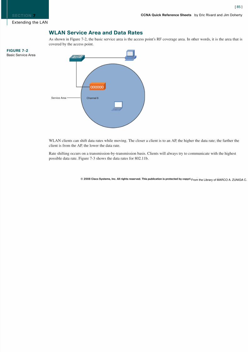
8/12/2019 59811139 CCNA Quick Reference Sheets
http://slidepdf.com/reader/full/59811139-ccna-quick-reference-sheets 85/311
Extending the LAN
WLAN Service Area and Data RatesAs shown in Figure 7-2, the basic service area is the access point’s RF coverage area. In other words, it is the area that iscovered by the access point.
WLAN clients can shift data rates while moving. The closer a client is to an AP, the higher the data rate; the farther theclient is from the AP, the lower the data rate.
Rate shifting occurs on a transmission-by-transmission basis. Clients will always try to communicate with the highestpossible data rate. Figure 7-3 shows the data rates for 802.11b.
© 2008 Cisco Systems, Inc. All rights reserved. This publication is protected by copyright. Please see page 311 for more details.
FIGURE 7-2Basic Service Area
Channel 6Service Area
From the Library of MARCO A. ZUNIGA C.
SECTION 7
[ 86 ]
CCNA Quick Reference Sheets by Eric Rivard and Jim Doherty

8/12/2019 59811139 CCNA Quick Reference Sheets
http://slidepdf.com/reader/full/59811139-ccna-quick-reference-sheets 86/311
Extending the LAN
Access Point ConfigurationAPs can be configured through a command-line interface or a browser GUI. APs should be configured with the followingparameters:
n IP address, subnet mask, and default gateway
n Wireless protocol (802.11g, 802.11a/b/g, 802.11a)n RF channel
n SSID
n Authentication method
n Encryption method
n Optional power adjustment
© 2008 Cisco Systems, Inc. All rights reserved. This publication is protected by copyright. Please see page 311 for more details.
FIGURE 7-3802.11b Data Rates
1 Mbps DSSS
2 Mbps DSSS
5.5 Mbps DSSS
11 Mbps DSSS
From the Library of MARCO A. ZUNIGA C.
8/12/2019 59811139 CCNA Quick Reference Sheets
http://slidepdf.com/reader/full/59811139-ccna-quick-reference-sheets 87/311
SECTION 8
[ 88 ]
CCNA Quick Reference Sheets by Eric Rivard and Jim Doherty
8/12/2019 59811139 CCNA Quick Reference Sheets
http://slidepdf.com/reader/full/59811139-ccna-quick-reference-sheets 88/311
Exploring the Functions of Routing
Part III: Connecting LANs
Section 8Exploring the Functions of Routing
Router OverviewRouting is the act of finding a path to a destination and moving data across this path from source to destination. Therouting process uses network routing tables, protocols, and algorithms to determine the most efficient path for forwardingthe IP packet.
Router FunctionRouters have the following two key functions:
n Path determination: Routing tables and network addresses transmit packets through the network. The process of routing includes determining the optimum path through the network. Routers do this by using a routing protocol tocommunicate the network information from the router’s own routing table with neighboring router’s.
n Packet forwarding: After the path is determined, a router forwards the packets through its network interface towardthe destination.
© 2008 Cisco Systems, Inc. All rights reserved. This publication is protected by copyright. Please see page 311 for more details.From the Library of MARCO A. ZUNIGA C.
SECTION 8
[ 89 ]
CCNA Quick Reference Sheets by Eric Rivard and Jim Doherty

8/12/2019 59811139 CCNA Quick Reference Sheets
http://slidepdf.com/reader/full/59811139-ccna-quick-reference-sheets 89/311
Exploring the Functions of Routing
Key Information a Router NeedsIn Figure 8-1, for hosts in network 10.120.2.0 to communicate with hosts in network 172.16.1.0, a router needs thefollowing key information:
n Destination address: The destination (typically an IP address) of the information being sent
n Sources of information: Where the information came from (typically an IP address)
n Possible routes: The likely routes to get from source to destination
n Best route: The best path to the intended destination
n Status of routes: The known paths to destination
© 2008 Cisco Systems, Inc. All rights reserved. This publication is protected by copyright. Please see page 311 for more details.
FIGURE 8-1
Routing Tables
172.17.3.0
S1
S0 S0
Connected
EIGRP
RIP
Routed Protocol: IPRouting Protocol: RIP, EIGRP
Network Protocol
DestinationNetwork
ExitInterface
10.120.2.0 E0
172.17.3.0
172.16.2.0
S1
E0 S0
10.120.2.0172.16.1.0
From the Library of MARCO A. ZUNIGA C.
SECTION 8
[ 90 ]
CCNA Quick Reference Sheets by Eric Rivard and Jim Doherty

8/12/2019 59811139 CCNA Quick Reference Sheets
http://slidepdf.com/reader/full/59811139-ccna-quick-reference-sheets 90/311
Exploring the Functions of Routing
Routing Versus RoutedNetwork layer protocols are either routed protocols or routing protocols. These are defined as follows:
n A routed protocol:n Is any network layer protocol that provides enough information within its address to allow the packet to direct
user traffic.
n Defines the address format and use of fields within the packet.
Routed protocols include IP, Internetwork Packet Exchange (IPX), AppleTalk, and others.
n Routing protocols determine how routed protocols are used by:
n Providing mechanisms for sharing routing information.
n Allowing routers to update each other about network changes.
Routing Information Protocol (RIP), Enhanced IGRP (EIGRP), Open Shortest Path First (OSPF), and BorderGateway Protocol (BGP) are examples of routing protocols.
Path DeterminationRouting tables and network addresses transmit packets through the network. The process of routing includes determiningthe optimum path through the network and then moving the packets along the path.
A router can use the following types of entries in the routing table to select the best path:
n Static routes: Manually entered routes in the routing table
n Dynamic routes: Routes dynamically learned from a routing protocol
n Default routes: A static or dynamic route that tells the router where to route packets not explicitly in the router’srouting table
© 2008 Cisco Systems, Inc. All rights reserved. This publication is protected by copyright. Please see page 311 for more details.From the Library of MARCO A. ZUNIGA C.
SECTION 8
[ 91 ]
CCNA Quick Reference Sheets by Eric Rivard and Jim Doherty

8/12/2019 59811139 CCNA Quick Reference Sheets
http://slidepdf.com/reader/full/59811139-ccna-quick-reference-sheets 91/311
Exploring the Functions of Routing
Routing TableA router is constantly learning about routes in the network and storing this information in its routing table. The routeruses its table to make forwarding decisions. The router learns about routes in one of three ways:
n Directly connected networks
n Statically (routing information entered by the network administrator)
n Dynamically (a routing process running in the network)
Information stored in a routing table includes destination/next-hop and routing metrics. Destination/next-hop tells therouter whether the destination is directly connected or is available through an adjacent router.
Dynamic Routing ProtocolsRouting protocols use their own rules and metrics to build and update routing tables automatically. Routing metrics aremeasures of path desirability. Different protocols use different metrics. Some common metrics are as follows:
n Bandwidth: The link’s data capacity.
n Delay: The time required to move the packet from the current router to the destination. This depends on the band-width of intermediate links, port delays at each router, congestion, and distance.
n Load: The amount of activity on the network.
n Reliability: The error rate of each network link.
n Hop count: The number of routers the packet must travel through before reaching the destination.
n Cost: An arbitrary value based on bandwidth, expense, and other metrics assigned by the administrator.
© 2008 Cisco Systems, Inc. All rights reserved. This publication is protected by copyright. Please see page 311 for more details.From the Library of MARCO A. ZUNIGA C.
SECTION 8
[ 92 ]
CCNA Quick Reference Sheets by Eric Rivard and Jim Doherty

8/12/2019 59811139 CCNA Quick Reference Sheets
http://slidepdf.com/reader/full/59811139-ccna-quick-reference-sheets 92/311
Exploring the Functions of Routing
Routing MethodsRouting protocols are designed around one of the following routing methods:
n Distance vector routing: Routers using distance vector–based routing share routing table information with eachother. This method of updating is called “routing by rumor.” Each router receives updates from its direct neighbor. InFigure 8-2, Router B shares information with Routers A and C. Router C shares routing information with Routers Band D. In this case, the routing information is distance vector metrics (such as the number of hops). Each routerincrements the metrics as they are passed on (incrementing hop count, for example). Distance accumulation keepstrack of the routing distance between any two points in the network, but the routers do not know the exact topologyof an internetwork. RIP is an example of a distance vector routing protocol.
n Link-state routing: The link-state–based routing algorithm (also known as shortest path first [SPF]) maintains adatabase of topology information. Unlike the distance vector algorithm, link-state routing maintains full knowledge
© 2008 Cisco Systems, Inc. All rights reserved. This publication is protected by copyright. Please see page 311 for more details.
FIGURE 8-2Distance VectorRouting Protocols
Vector—In Which Direction?Distance—How Far?
RoutingTable
RoutingTable
RoutingTable
RoutingTable
D
AC
B
D AC B
From the Library of MARCO A. ZUNIGA C.
SECTION 8
[ 93 ]
CCNA Quick Reference Sheets by Eric Rivard and Jim Doherty

8/12/2019 59811139 CCNA Quick Reference Sheets
http://slidepdf.com/reader/full/59811139-ccna-quick-reference-sheets 93/311
Exploring the Functions of Routing
of distant routers and how they interconnect. Network information is shared in the form of link-state advertisements(LSA). See Figure 8-3. Link-state routing provides better scaling than distance vector routing for the followingreasons:
n Link-state sends only topology changes. Distance vector sends complete routing tables.n Link-state updates are sent less often than distance vector updates.
n Link-state uses a two-state hierarchy (areas and autonomous systems), which limits the scope of route changes.
n Link-state supports classless addressing and summarization.
n Link-state routing converges fast and is robust against routing loops, but it requires a great deal of memory andstrict network designs.
OSPF and Intermediate System–to–Intermediate System (IS-IS) are examples of link-state routing protocols.
© 2008 Cisco Systems, Inc. All rights reserved. This publication is protected by copyright. Please see page 311 for more details.
FIGURE 8-3Link-State RoutingProtocols
TopologicalDatabase
Link-State Packets
SPF
Algorithm
Shortest Path F irst Tree
RoutingTable
A
B
D
C
From the Library of MARCO A. ZUNIGA C.
SECTION 8
[ 94 ]
CCNA Quick Reference Sheets by Eric Rivard and Jim Doherty

8/12/2019 59811139 CCNA Quick Reference Sheets
http://slidepdf.com/reader/full/59811139-ccna-quick-reference-sheets 94/311
Exploring the Functions of Routing
n Advanced distance vector: Combines aspects of both distance vector and link-state protocols. Balanced hybridrouting uses distance vectors with more accurate metrics, but unlike distance vector routing protocols, it updatesonly when there is a topology change. Balanced hybrid routing provides faster convergence while limiting the use of
resources such as bandwidth, memory, and processor overhead. Cisco Enhanced IGRP (EIGRP) is an example of abalanced hybrid protocol.
Understanding Binary BasicsComputers use a numbering system based on only 1s and 0s. This type of system is called binary or base 2. This number-ing system might seem awkward at first glance, but it uses the same logic as the base 10 system we use every day. Aswith base 10, binary counting starts with the “ones” column until all the numbers are exhausted, and then it rolls over tothe next column, which is a power of the base. For example, base 10 has ten numbers (0 through 9). When counting, you
start in the “ones” column and count until you reach the highest unit. Then you move to the “tens” column. This contin-ues with successive powers (1, 10 1, 10 2, 10 3). The binary system’s columns or placeholders are 2 0, 21, 22, 23, and so on.Table 8-1 shows the values for the first seven places.
Table 8-1 BinaryBase 2 Numbering System
Number of Symbols 2
Symbols 0, 1
Base Exponent 2 7 26 25 24 23 22 21 20
Place Value 128 64 32 16 8 4 2 1
Example: Convert 47 to Binary 0 0 1 0 1 1 1 1
© 2008 Cisco Systems, Inc. All rights reserved. This publication is protected by copyright. Please see page 311 for more details.From the Library of MARCO A. ZUNIGA C.
SECTION 8
[ 95 ]
CCNA Quick Reference Sheets by Eric Rivard and Jim Doherty
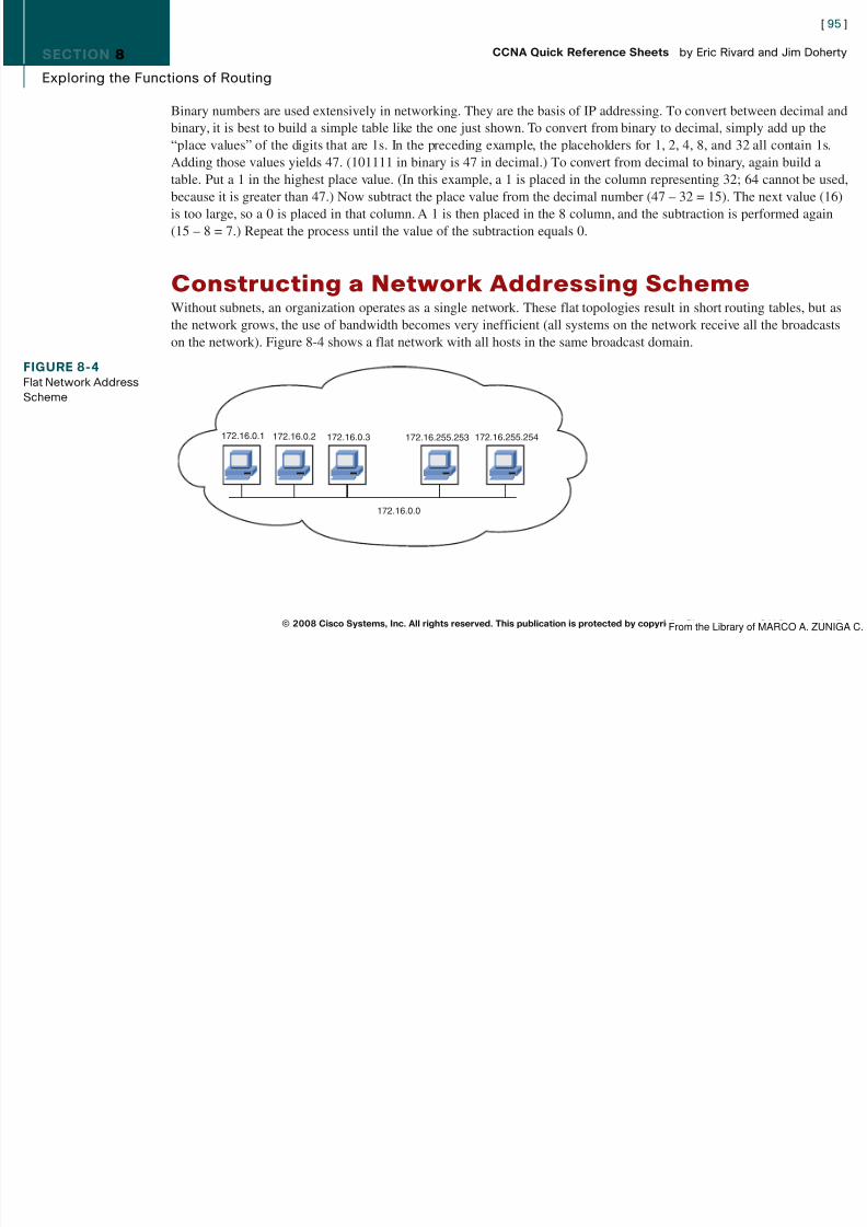
8/12/2019 59811139 CCNA Quick Reference Sheets
http://slidepdf.com/reader/full/59811139-ccna-quick-reference-sheets 95/311
Exploring the Functions of Routing
Binary numbers are used extensively in networking. They are the basis of IP addressing. To convert between decimal andbinary, it is best to build a simple table like the one just shown. To convert from binary to decimal, simply add up the“place values” of the digits that are 1s. In the preceding example, the placeholders for 1, 2, 4, 8, and 32 all contain 1s.
Adding those values yields 47. (101111 in binary is 47 in decimal.) To convert from decimal to binary, again build atable. Put a 1 in the highest place value. (In this example, a 1 is placed in the column representing 32; 64 cannot be used,because it is greater than 47.) Now subtract the place value from the decimal number (47 – 32 = 15). The next value (16)is too large, so a 0 is placed in that column. A 1 is then placed in the 8 column, and the subtraction is performed again(15 – 8 = 7.) Repeat the process until the value of the subtraction equals 0.
Constructing a Network Addressing SchemeWithout subnets, an organization operates as a single network. These flat topologies result in short routing tables, but asthe network grows, the use of bandwidth becomes very inefficient (all systems on the network receive all the broadcastson the network). Figure 8-4 shows a flat network with all hosts in the same broadcast domain.
© 2008 Cisco Systems, Inc. All rights reserved. This publication is protected by copyright. Please see page 311 for more details.
FIGURE 8-4Flat Network AddressScheme
172.16.0.1 172.16.0.2 172.16.0.3 172.16.255.253 172.16.255.254
172.16.0.0
From the Library of MARCO A. ZUNIGA C.
SECTION 8
l h f
[ 96 ]
CCNA Quick Reference Sheets by Eric Rivard and Jim Doherty

8/12/2019 59811139 CCNA Quick Reference Sheets
http://slidepdf.com/reader/full/59811139-ccna-quick-reference-sheets 96/311
Exploring the Functions of Routing
Network addressing can be made more efficient by breaking the addresses into smaller segments, or subnets. Subnettingprovides additional structure to an addressing scheme without altering the addresses.
In Figure 8-5, the network address 172.16.0.0 is subdivided into four subnets: 172.16.1.0, 172.16.2.0, 172.16.3.0, and172.16.4.0. If traffic were evenly distributed to each end station, the use of subnetting would reduce the overall trafficseen by each end station by 75 percent.
Subnet MaskAs shown in Figure 8-6, a subnet mask is a 32-bit value written as four octets. In the subnet mask, each bit is used to
© 2008 Cisco Systems, Inc. All rights reserved. This publication is protected by copyright. Please see page 311 for more details.
FIGURE 8-5Subnetted AddressScheme
172.16.3.0
172.16.4.0
172.16.1.0 172.16.2.0
From the Library of MARCO A. ZUNIGA C.
SECTION 8
E l i h F i f R i
[ 97 ]
CCNA Quick Reference Sheets by Eric Rivard and Jim Doherty

8/12/2019 59811139 CCNA Quick Reference Sheets
http://slidepdf.com/reader/full/59811139-ccna-quick-reference-sheets 97/311
Exploring the Functions of Routing
determine how the corresponding bit in the IP address should be interpreted (network, subnet, or host). The subnet mask bits are coded as follows:
n Binary 1 for the network bits
n Binary 1 for the subnet bits
n Binary 0 for the host bits
Although dotted-decimal is most common, the subnet can be represented in several ways:
n Dotted-decimal: 172.16.0.0 255.255.0.0
n Bit count: 172.16.0.0/16
n Hexadecimal: 172.16.0.0 0xFFFF0000
© 2008 Cisco Systems, Inc. All rights reserved. This publication is protected by copyright. Please see page 311 for more details.
FIGURE 8-6IP Address andSubnet Mask IP
Address
DefaultSubnet
Mask
8-bitSubnet
Mask
Subnet
Also Written as "/16" Where 16 Represents the Number of 1s in the Mask.
Also Written as "/24" Where 24 Represents the Number of 1s in the Mask.
Network Host
172 16 0 0
Network Host
25511111111
25511111111
000000000
000000000
Network Host
255 255 255 0
From the Library of MARCO A. ZUNIGA C.
SECTION 8
E l i th F ti f R ti
[ 98 ]
CCNA Quick Reference Sheets by Eric Rivard and Jim Doherty

8/12/2019 59811139 CCNA Quick Reference Sheets
http://slidepdf.com/reader/full/59811139-ccna-quick-reference-sheets 98/311
Exploring the Functions of Routing
The ip netmask-format command can specify the display format of network masks for the router. Dotted-decimal is thedefault.
Default Subnet MasksEach address class has a default subnet mask. The default subnet masks only the network portion of the address, theeffect of which is no subnetting. With each bit of subnetting beyond the default, you can create 2 n–2 subnets. Figure 8-7and Table 8-2 show the effect of increasing the number of subnet bits.
© 2008 Cisco Systems, Inc. All rights reserved. This publication is protected by copyright. Please see page 311 for more details.
FIGURE 8-7Default Subnet Masks Bits:
Bits:
Bits:
Bits:
Class A:
Class B:
Class C:
Class D:
1 8 9 16 17 24 25 32
Range (224-239)
1110 MMMM MulticastGroup
MulticastGroup
MulticastGroup
1 8 9 16 17 24 25 32
Range (192-223)
110 NNNNN Network Network Host
1 8 9 16 17 24 25 32
Range (128-191)
10 NNNNNN Network Host Host
1 8 9 16 17 24 25 32
Range (1-126)
0NNNNNNN Host Host Host
From the Library of MARCO A. ZUNIGA C.
SECTION 8
E l i g th F ti f R ti g
[ 99 ]
CCNA Quick Reference Sheets by Eric Rivard and Jim Doherty

8/12/2019 59811139 CCNA Quick Reference Sheets
http://slidepdf.com/reader/full/59811139-ccna-quick-reference-sheets 99/311
Exploring the Functions of Routing
Table 8-2 SubnettingAddress Subnet Address Number of Subnets Comments
10.5.22.5/8 255.0.0.0 0 This is the default Class A subnet address. The
mask includes only the network portion of theaddress and provides no additional subnets.
10.5.22.5/16 255.255.0.0 254 This Class A subnet address has 16 bits ofsubnetting, but only the bits in the second octet(those beyond the default) contribute to thesubnetting.
155.13.22.11/16 255.255.0.0 0 In this case, 16 bits are used for subnetting, butbecause the default for a Class B address is 16 bits,no additional subnets are created.
155.13.10.11/26 255.255.255.192 1022 This case has a total of 26 bits of subnetting, butthe Class B address can use only 10 of them tocreate subnets. The result creates 1024 subnets.
How Routers Use Subnet MasksTo determine the subnet of the address, a router performs a logical AND operation with the IP address and subnet mask.Recall that the host portion of the subnet mask is all 0s. The result of this operation is that the host portion of the addressis removed, and the router bases its decision only on the network portion of the address.
In Figure 8-8, the host bits are removed, and the network portion of the address is revealed. In this case, a 10-bit subnetaddress is used, and the network (subnet) number 172.16.2.128 is extracted.
© 2008 Cisco Systems, Inc. All rights reserved. This publication is protected by copyright. Please see page 311 for more details.From the Library of MARCO A. ZUNIGA C.
SECTION 8
Exploring the Functions of Routing
[ 100 ]
CCNA Quick Reference Sheets by Eric Rivard and Jim Doherty

8/12/2019 59811139 CCNA Quick Reference Sheets
http://slidepdf.com/reader/full/59811139-ccna-quick-reference-sheets 100/311
Exploring the Functions of Routing
Broadcast AddressesBroadcast messages are sent to every host on the network. Two kinds of broadcasts exist:
n Directed broadcasts can broadcast to all hosts within a subnet and to all subnets within a network. (170.34.2.255sends a broadcast to all hosts in the 170.34.2.0 subnet.)
n Flooded broadcasts (255.255.255.255) are local broadcasts within a subnet.
Identifying Subnet AddressesGiven an IP address and subnet mask, you can identify the subnet address, broadcast address, first usable address, andlast usable address using the following method, which is displayed in Figure 8-9:
Step 1. Write the 32-bit address, and write the subnet mask below that.
Step 2. Draw a vertical line just after the last 1 bit in the subnet mask.
© 2008 Cisco Systems, Inc. All rights reserved. This publication is protected by copyright. Please see page 311 for more details.
FIGURE 8-8Identifying Network Portion of Address
Network Subnet Host
10101100 00010000 00000010 10100000
11111111 11111111 11111111 11000000
10101100 00010000 00000010 10000000
Network Number
1 2 8
1 9 2
2 2 4
2 4 0
2 4 8
2 5 2
2 5 4
2 5 5
1 2 8
1 9 2
2 2 4
2 4 0
2 4 8
2 5 2
2 5 4
2 5 5
16172 2 128
255.255. 255 .192
172.16.2.160
From the Library of MARCO A. ZUNIGA C.
SECTION 1
Introduction
[ 101 ]
CCNA Quick Reference Sheets by Eric Rivard and Jim Doherty

8/12/2019 59811139 CCNA Quick Reference Sheets
http://slidepdf.com/reader/full/59811139-ccna-quick-reference-sheets 101/311
Introduction
Step 3. Copy the portion of the IP address to the left of the line. Place all 0s for the remaining free spaces to theright. This is the subnet number.
Step 4. Copy the portion of the IP address to the left of the line. Place all 1s for the remaining free spaces to the
right. This is the broadcast address.Step 5. Copy the portion of the IP address to the left of the line. Place all 0s in the remaining free spaces until you
reach the last free space. Place a 1 in that free space. This is your first usable address.
Step 6. Copy the portion of the IP address to the left of the line. Place all 1s in the remaining free spaces until youreach the last free space. Place a 0 in that free space. This is your last usable address.
How to Implement Subnet PlanningSubnetting decisions should always be based on growth estimates rather than current needs.
To plan a subnet, follow these steps:
Step 1. Determine the number of subnets and hosts per subnet required.
© 2008 Cisco Systems, Inc. All rights reserved. This publication is protected by copyright. Please see page 311 for more details.
FIGURE 8-9Identifying SubnetAddresses
174.24.4.176
255.255.255.192
174.24.4.128
174.24.4.191
174.24.4.129
174.24.4.190
10101110 00011000 00000100 10110000
11111111 11111111 11111111 11000000
10101110 00011000 00000100 10000000
10101110 00011000 00000100 10111111
10101110 00011000 00000100 10000001
10101110 00011000 00000100 10111110
Host
Mask
Subnet
Broadcast
First
Last
174 24 4 176
From the Library of MARCO A. ZUNIGA C.
SECTION 1
Introduction
[ 102 ]
CCNA Quick Reference Sheets by Eric Rivard and Jim Doherty

8/12/2019 59811139 CCNA Quick Reference Sheets
http://slidepdf.com/reader/full/59811139-ccna-quick-reference-sheets 102/311
Introduction
Step 2. The address class you are assigned, and the number of subnets required, determine the number of subnettingbits used. For example, with a Class C address and a need for 20 subnets, you have a 29-bit mask (255.255.255.248). This allows the Class C default 24-bit mask and 5 bits required for 20 subnets. (The
formula 2n
–2 yields only 14 subnets for 4 bits, so 5 bits must be used.)Step 3. The remaining bits in the last octet are used for the host field. In this case, each subnet has 2 3–2, or 6, hosts.
Step 4. The final host addresses are a combination of the network/subnet plus each host value. In Figure 8-10, thehosts on the 192.168.5.32 subnet would be addressed as 192.168.5.33, 192.168.5.34, 192.168.5.35, and soforth.
Configuring Static RoutesTo configure a static route on a Cisco router, enter the following global command:
ip route destination-network [ mask ] { next-hop-address | outbound- interface } [ distance ] [ permanent ]
© 2008 Cisco Systems, Inc. All rights reserved. This publication is protected by copyright. Please see page 311 for more details.
FIGURE 8-10Subnetting a Network
192.168.5.16
192.168.5.48
OtherSubnets
192.168.5.32
20 Subnets5 Hosts per SubnetClass C Address:192.168.5.0
From the Library of MARCO A. ZUNIGA C.
SECTION 1
Introduction
[ 103 ]
CCNA Quick Reference Sheets by Eric Rivard and Jim Doherty

8/12/2019 59811139 CCNA Quick Reference Sheets
http://slidepdf.com/reader/full/59811139-ccna-quick-reference-sheets 103/311
Introduction
Here’s an example:
RouterB(config)# ip route 172.17.0.0 255.255.0.0 172.16.0.1
This example instructs the router to route to 172.16.0.1 any packets that have a destination of 172.17.0.0 to
172.17.255.255.
The distance parameter defines the administrative distance or the route. The value for distance is a number from 1 to 254(1 is the default if not defined) that rates the distance in hops of the destination. For example, a distance of 1 means thatthe destination is one hop away. If a router has two routes to the same destination, the route with the lowest distance isused.
The permanent statement specifies that the route will not be removed even if the router interface shuts down.
Default RouteA default route is a special type of route with an all-0s network and network mask. The default route directs any packetsfor which a next hop is not specifically listed in the routing table. By default, if a router receives a packet to a destinationnetwork that is not in its routing table, it drops the packet. When a default route is specified, the router does not drop thepacket. Instead, it forwards the packet to the IP address specified in the default route.
To configure a static default route on a Cisco router, enter the following global configuration command:
ip route 0.0.0.0 0.0.0.0 [ ip-address-of-the-next-hop-router | outbound-interface ]
For example, the following command configures the router to route all packets with destinations not in its routing table toIP 172.16.0.2:
RouterB(config)# ip route 0.0.0.0 0.0.0.0 172.16.0.2
© 2008 Cisco Systems, Inc. All rights reserved. This publication is protected by copyright. Please see page 311 for more details.From the Library of MARCO A. ZUNIGA C.
SECTION 1
Introduction
[ 104 ]
CCNA Quick Reference Sheets by Eric Rivard and Jim Doherty

8/12/2019 59811139 CCNA Quick Reference Sheets
http://slidepdf.com/reader/full/59811139-ccna-quick-reference-sheets 104/311
Introduction
Verifying RoutingThe show ip route command, as follows, verifies routing tables:
RouterA# show ip routeCodes: C - connected, S - static, R - RIP, M - mobile, B - BGP
D - EIGRP, EX - EIGRP external, O - OSPF, IA - OSPF inter area
N1 - OSPF NSSA external type 1, N2 - OSPF NSSA external type 2
E1 - OSPF external type 1, E2 - OSPF external type 2
i - IS-IS, su - IS-IS summary, L1 - IS-IS level-1, L2 - IS-IS level-2
ia - IS-IS inter area, * - candidate default, U - per-user static route
o - ODR, P - periodic downloaded static route
Gateway of last resort is 10.1.10.1 to network 0.0.0.0
10.0.0.0/8 is variably subnetted, 9 subnets, 2 masks
D 10.1.10.0/24 [90/28416] via 10.1.10.254, 2w0d, FastEthernet0/0
D 10.1.20.0/24 [90/28416] via 10.1.10.254, 2w0d, FastEthernet0/0
C 10.1.10.0/24 is directly connected, FastEthernet0/0
S 10.0.0.0/8 [1/0] via 10.1.10.0
D 10.1.60.0/24 [90/28416] via 10.1.10.254, 2w0d, FastEthernet0/0D 10.1.50.0/24 [90/28416] via 10.1.10.254, 2w0d, FastEthernet0/0
D 10.1.40.0/24 [90/28416] via 10.1.10.254, 2w0d, FastEthernet0/0
D 10.1.100.0/24 [90/28416] via 10.1.10.254, 2w0d, FastEthernet0/0D 10.1.254.0/24 [90/28416] via 10.1.10.254, 2w0d, FastEthernet0/0
D 192.168.0.0/24 [90/2172416] via 192.168.1.2, 1w6d, Serial0/0/0
192.168.1.0/24 is variably subnetted, 2 subnets, 2 masks
C 192.168.1.0/30 is directly connected, Serial0/0/0D 192.168.1.0/24 is a summary, 1w6d, Null0
S* 0.0.0.0/0 [1/0] via 10.1.10.1
© 2008 Cisco Systems, Inc. All rights reserved. This publication is protected by copyright. Please see page 311 for more details.From the Library of MARCO A. ZUNIGA C.

8/12/2019 59811139 CCNA Quick Reference Sheets
http://slidepdf.com/reader/full/59811139-ccna-quick-reference-sheets 105/311
SECTION 9
Configuring a Cisco Router
[ 106 ]
CCNA Quick Reference Sheets by Eric Rivard and Jim Doherty

8/12/2019 59811139 CCNA Quick Reference Sheets
http://slidepdf.com/reader/full/59811139-ccna-quick-reference-sheets 106/311
Configuring a Cisco Router
© 2008 Cisco Systems, Inc. All rights reserved. This publication is protected by copyright. Please see page 311 for more details.
FIGURE 9-1Router BootFlow Chart
Router Boot Flowchart
NO
YES
YES
YES
NO
YES
YES
NO
NO
YES
NO
YES
NO YES
NO
YES
NO
RunROM
Monitor
SetupDialog
NormalStart Up
Complete
ValidConfig
?
ValidIOS inFlash
?
NO
Config RegBit 6=1
?
Load IOS
Use IOS in ROM
x
Do What
Use IOS from
Use File fromSuccess
?
Config RegBit 13=1
BootField=1
0x1
5Failures
Run
Load
BootField=0
0x0
STARTCheck Start-up
BootSystem
Commands
Attempt to Get
Network
(RXBoot mode)
POST
Bootstrap
Config They Say
Network
Flash
IOS from
From the Library of MARCO A. ZUNIGA C.
SECTION 9
Configuring a Cisco Router
[ 107 ]
CCNA Quick Reference Sheets by Eric Rivard and Jim Doherty

8/12/2019 59811139 CCNA Quick Reference Sheets
http://slidepdf.com/reader/full/59811139-ccna-quick-reference-sheets 107/311
Co gu g a C sco oute
When the setup mode configuration process is completed, the setup command gives you the following options:
n [0]: Go to the EXEC prompt without saving the created configuration.
n [1]: Go back to the beginning of setup without saving the created configuration.
n [2]: Accept the created configuration, save it to NVRAM, and exit to EXEC mode.
Default answers appear in square brackets ([]). Pressing Enter accepts the defaults. At the first setup prompt, you canenter No to discontinue the setup. The setup process can be aborted at any time by pressing Ctrl-C.
Router ComponentsThe major router components are as follows:
n RAM: Random-access memory contains key software (IOS).
n ROM: Read-only memory contains startup microcode.
n NVRAM: Nonvolatile RAM stores the configuration.
n Configuration register: Controls the bootup method.
n Interfaces: The interface is the physical connection to the external devices.
n Flash memory: Flash contains the Cisco IOS Software image.
Logging In to the RouterCisco IOS Software provides a command interpreter called the EXEC. The EXEC interprets the commands that areentered and carries out the corresponding operations. To access EXEC mode, you must log in to the router through the
© 2008 Cisco Systems, Inc. All rights reserved. This publication is protected by copyright. Please see page 311 for more details.From the Library of MARCO A. ZUNIGA C.
SECTION 9
Configuring a Cisco Router
[ 108 ]
CCNA Quick Reference Sheets by Eric Rivard and Jim Doherty

8/12/2019 59811139 CCNA Quick Reference Sheets
http://slidepdf.com/reader/full/59811139-ccna-quick-reference-sheets 108/311
g g
command line. Two EXEC modes exist, as shown in Figure 9-2:
n User EXEC level provides a limited number of basic commands.
n Privileged EXEC (enable mode) level allows you to access all router commands. This level can be password-protected. The enable command allows access to this mode (disable exits to user mode).
Displaying Router StatusOutput from the following show commands provides valuable information about the router status:
n show running-configuration displays the currently active configuration in memory, including any changes made inthe session that have not yet been saved.
n show startup-config displays the last saved configuration.
n show version displays information about the system hardware and software.
n show interfaces displays information on connections and ports that connect with other devices.
© 2008 Cisco Systems, Inc. All rights reserved. This publication is protected by copyright. Please see page 311 for more details.
FIGURE 9-2Cisco IOS SoftwareEXEC Modes
Console
wg_ro_c con0 is now available
Press RETURN to get started
wg_ro_c>wg_ro_c> enable
wg_ro_c#
wg_ro_c# disable
wg_ro_c>
wg_ro_c> logout
User-Mode Prompt
Privileged-Mode Prompt
From the Library of MARCO A. ZUNIGA C.
SECTION 9
Configuring a Cisco Router
[ 109 ]
CCNA Quick Reference Sheets by Eric Rivard and Jim Doherty

8/12/2019 59811139 CCNA Quick Reference Sheets
http://slidepdf.com/reader/full/59811139-ccna-quick-reference-sheets 109/311
g g
Configuring a RouterFrom privileged EXEC mode, the configure terminal command provides access to global configuration mode. Fromglobal configuration mode, you can access these specific configuration modes:
n Interface: Configures operations on a per-interface basis
n Subinterface: Configures multiple virtual interfaces
n Controller: Supports commands that configure controllers (such as E1 and T1)
n Line: Configures the operation of a terminal line
n Router: Configures IP routing protocols
Major Command/Subcommand RelationshipFigure 9-3 shows the major command and subcommand relationships. Commands that indicate a process or interface thatwill be configured are called major commands.
Major commands cause the CLI to enter a specific configuration mode.
Major commands have no effect unless they are immediately followed by a subcommand that supplies the configurationentry, as follows:
Router(config)# interface serial 0
Router(config-if)# shutdown
Router(config)# router rip
Router(config-router)# network 10.0.0.0
© 2008 Cisco Systems, Inc. All rights reserved. This publication is protected by copyright. Please see page 311 for more details.From the Library of MARCO A. ZUNIGA C.
SECTION 9
Configuring a Cisco Router
[ 110 ]
CCNA Quick Reference Sheets by Eric Rivard and Jim Doherty
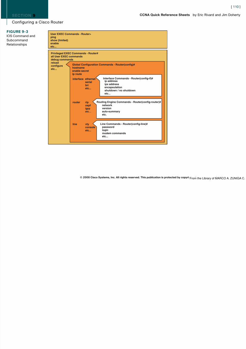
8/12/2019 59811139 CCNA Quick Reference Sheets
http://slidepdf.com/reader/full/59811139-ccna-quick-reference-sheets 110/311
g g
© 2008 Cisco Systems, Inc. All rights reserved. This publication is protected by copyright. Please see page 311 for more details.
FIGURE 9-3IOS Command andSubcommandRelationships
Privileged EXEC Commands - Router#all User EXEC commandsdebug commandsreloadconfigureetc...
Global Configuration Commands - Router(config)#hostnameenable secretip route
interface ethernet serial bri etc...
Interface Commands - Router(config-if)#ip addressipx addressencapsulation
shutdown / no shutdownetc...
Routing Engine Commands - Router(config-router)#network versionauto-summaryetc.
line vty console etc...
Line Commands - Router(config-line)#passwordloginmodem commandsetc...
User EXEC Commands - Router>pingshow (limited)enableetc...
router rip ospf igrp etc...
From the Library of MARCO A. ZUNIGA C.
SECTION 9
Configuring a Cisco Router
[ 111 ]
CCNA Quick Reference Sheets by Eric Rivard and Jim Doherty

8/12/2019 59811139 CCNA Quick Reference Sheets
http://slidepdf.com/reader/full/59811139-ccna-quick-reference-sheets 111/311
Assigning a Router Name ExampleThe hostname command, as follows, names a router (or a switch):
Router> enable
Router# configure terminal
Router(config)# hostname Dallas
Configuring a Serial InterfaceThe following example demonstrates the command syntax needed to configure a serial interface on a router:
Router# configure terminalRouter(config)# interface s1Router(config-if)# clock rate 64000
Router(config-if)# bandwidth 64
Router# show interface serial 1
Router# show controller displays the information about the physical interface and if it is a DTE or DCE.
Enabling or Disabling an Interface ExampleBy default, all interfaces on a router are initially disabled. The following commands show you how to enable or disable arouter interface:
Router# configure terminal
Router(config)# interface s1
Router(config)# no shutdown enables the interface
Router(config)# shutdown disables the interface
© 2008 Cisco Systems, Inc. All rights reserved. This publication is protected by copyright. Please see page 311 for more details.
NOTEUnambiguous abbrevia-tions of commands areallowed. Abbreviations of
delimiters are notallowed. For example, aclock rate of 64,000cannot be abbreviated as64. The bandwidthcommand overrides thedefault bandwidth. Thebandwidth entered has noeffect on the line’s actualspeed; however, itchanges the metric of thelink as seen by routingprotocols.
From the Library of MARCO A. ZUNIGA C.

8/12/2019 59811139 CCNA Quick Reference Sheets
http://slidepdf.com/reader/full/59811139-ccna-quick-reference-sheets 112/311
SECTION 9
Configuring a Cisco Router
[ 113 ]
CCNA Quick Reference Sheets by Eric Rivard and Jim Doherty

8/12/2019 59811139 CCNA Quick Reference Sheets
http://slidepdf.com/reader/full/59811139-ccna-quick-reference-sheets 113/311
Exploring the Packet-Delivery ProcessFor hosts on an IP network to communicate with each other, they need a Layer 2 address (MAC address) and an IPaddress.
IP-enabled hosts use ARP to map the MAC address to the IP address when communicating with hosts on a local segment.Each host maintains an ARP table that contains the IP–to–MAC address mappings (see Figure 9-5).
© 2008 Cisco Systems, Inc. All rights reserved. This publication is protected by copyright. Please see page 311 for more details.
FIGURE 9-4Displaying InterfaceLine and Data-Link Status
Router# sh int s0Serial10 is up, line protocol is up Hardware is PQUICC with Fractional T1 CSU/DSU Internet address is 192.168.1.1/30
Serial0 is up, line protocol is upSerial0 is up, line protocol is downSerial0 is down, line protocol is downSerial0 is administratively down, line protocol is down
Operational–Connection Problem-Interface Problem-Disabled-
Carrier Detect(Layer 1)
Keepalives(Layer 2)
FIGURE 9-5Host-to-Host PacketDelivery
A B
L2 = 1111.1111.1111L3 = 192.168.1.2
L2 = 1111.3333.3333L3 = 192.168.1.3
DST MAC:1111.3333.3333
SRC MAC:1111.1111.1111
DST IP:192.168.1.3
SRC IP:192.168.1.2
From the Library of MARCO A. ZUNIGA C.
SECTION 9
Configuring a Cisco Router
[ 114 ]
CCNA Quick Reference Sheets by Eric Rivard and Jim Doherty

8/12/2019 59811139 CCNA Quick Reference Sheets
http://slidepdf.com/reader/full/59811139-ccna-quick-reference-sheets 114/311
When an IP host wants to communicate with a host on a remote network, the local host will send an ARP request to findthe MAC address of the host’s default gateway. Because the remote host is on a remote network, the router will respondwith its local MAC address and the IP address of the remote host. In Figure 9-6, host A wants to communicate with hostB. Host A sends a packet with the destination MAC address of the router’s Ethernet interface and the IP address of hostB. The source MAC address and IP will be that of host A. When the router receives the packet, the router will take thepacket, strip off the MAC address information, and rewrite the MAC address with the source MAC address of the router’sexiting Ethernet interface and the destination MAC address of host B. The IP information does not change.
Using Common IOS ToolsYou can verify connectivity using the ping command. The ping command also tells you the minimum, average, andmaximum times for packets that make the round trip to the target system and back. You can assess the path’s reliabilityusing this command, as follows:
Router# ping 10.1.1.10Type escape sequence to abort.
Sending 5, 100-byte ICMP Echos to 10.1.1.10, timeout is 2 seconds:
!!!!!
Success rate is 100 percent (5/5), round-trip min/avg/max = 4/4/4 ms
© 2008 Cisco Systems, Inc. All rights reserved. This publication is protected by copyright. Please see page 311 for more details.
FIGURE 9-6Host-to-Host PacketDelivery Through aRouter
A B
L2 = 1111.1111.1111L3 = 192.168.1.2 L2 = 1111.3333.3333
L3 = 192.168.1.1L2 = 2222.3333.4444L3 = 192.168.10.1
L2 = 2222.4444.5555L3 = 192.168.10.3
DST MAC:1111.3333.3333
SRC MAC:1111.1111.1111
DST IP:192.168.10.3
SRC IP:192.168.1.2
DST MAC:3333.4444.5555
SRC MAC:2222.3333.4444
DST IP:192.168.10.3
SRC IP:192.168.1.2
From the Library of MARCO A. ZUNIGA C.
SECTION 9
Configuring a Cisco Router
[ 115 ]
CCNA Quick Reference Sheets by Eric Rivard and Jim Doherty

8/12/2019 59811139 CCNA Quick Reference Sheets
http://slidepdf.com/reader/full/59811139-ccna-quick-reference-sheets 115/311
You can use the trace command, as follows, to view the actual routes that packets take between devices:
Router# trace 10.1.1.10
Type escape sequence to abort.
Tracing the route to 10.1.1.10
1 10.1.1.10 4 msec 4 msec 4 msecRouter#
The show ip arp command displays the router’s ARP cache.
Router Security
Configuring Router Passwords: Console and TelnetThe following example configures passwords on the console and vty lines of a router to homer and bart:
Router(config)# line console 0
Router(config-line)# login
Router(config-line)# password homer
Router(config)# line vty 0 4
Router(config-line)# login
Router(config-line)# password bart
The numbers 0 through 4 in the line vty command specify the number of Telnet sessions allowed in the router. You canalso set up a different password for each line by using the line vty port number command.
© 2008 Cisco Systems, Inc. All rights reserved. This publication is protected by copyright. Please see page 311 for more details.From the Library of MARCO A. ZUNIGA C.
SECTION 9
Configuring a Cisco Router
[ 116 ]
CCNA Quick Reference Sheets by Eric Rivard and Jim Doherty

8/12/2019 59811139 CCNA Quick Reference Sheets
http://slidepdf.com/reader/full/59811139-ccna-quick-reference-sheets 116/311
Configuring Router Passwords: Enable and Secret PasswordsThe following configures an enable password of apu and an enable secret password of flanders:
Router(config)# enable password apu
Router(config)# enable secret flanders
The no enable password command disables the privileged EXEC mode password.
The no enable secret command disables the encrypted password.
The console, Telnet, and enable passwords are displayed unencrypted. To encrypt them, use the service password-encryp-tion global command, as follows:
Router(config)# service password-encryption
Configuring Login Banner and MOTDThe login banner is displayed before the username and password login prompts on a Cisco router. The login banner isconfigured using the banner login global command, as follows:
Router# config t
Enter configuration commands, one per line. End with CNTL/Z.Router(config)# banner login #
Enter TEXT message. End with the character ‘#’.
Notice! Only Authorized Personnel Are Allowed to Access This Device
#The MOTD is displayed before the login banner. It is displayed to anyone connecting to the router through Telnet, consoleport, or auxiliary port. Use the banner motd # text # global configuration command to configure the MOTD, as follows:
Router(conf ig)#banner m otd # <ENTER>Enter TEXT message. End with the character ‘#’.
Warning only authorized users many access this switch. <ENTER>
#
Router(config)#
© 2008 Cisco Systems, Inc. All rights reserved. This publication is protected by copyright. Please see page 311 for more details.
NOTEWhen the enable secretpassword is set, it is usedinstead of the enablepassword.
From the Library of MARCO A. ZUNIGA C.
SECTION 9
Configuring a Cisco Router
[ 117 ]
CCNA Quick Reference Sheets by Eric Rivard and Jim Doherty

8/12/2019 59811139 CCNA Quick Reference Sheets
http://slidepdf.com/reader/full/59811139-ccna-quick-reference-sheets 117/311
SSH AccessCisco recommends using SSH to encrypt communication between the Cisco device and the host. Telnet is unsecure, andall communication between the Cisco device and host is sent in clear text. Use the following steps to configure SSH
access:Step 1. Create a local username and password on the device.
Step 2. Assign a domain name to the device.
Step 3. Generate a security key.
Step 4. Enable SSH.
Step 5. Configure vty ports to authenticate using SSH.
Router(config)# username eric password 0 ciscopress
Router(config)# ip domain-name cisco.com
Router(config)# crypto key generate rsa
The name for the keys will be: router.cisco.com
Choose the size of the key modulus in the range of 360 to 2048 for yourGeneral Purpose Keys. Choosing a key modulus greater than 512 may take
a few minutes.
How many bits in the modulus [512]:
% Generating 512 bit RSA keys ...[OK]
Router(config)# ip ssh ver 2
Router(config)# line vty 0 15Router(config-line)# login local
Router(config-line)# transport input telnet ssh
© 2008 Cisco Systems, Inc. All rights reserved. This publication is protected by copyright. Please see page 311 for more details.From the Library of MARCO A. ZUNIGA C.
SECTION 9
Configuring a Cisco Router
[ 118 ]
CCNA Quick Reference Sheets by Eric Rivard and Jim Doherty

8/12/2019 59811139 CCNA Quick Reference Sheets
http://slidepdf.com/reader/full/59811139-ccna-quick-reference-sheets 118/311
Securing vty AccessBy default, after a vty password has been applied, any IP address can connect to vty ports. You should restrict access tovty ports to only specific IP address. This is done through standard access lists.
Standard access lists allow you to permit or deny traffic based on the source IP address. To restrict access to vty ports,you would create a standard access list that permits each authorized IP address to connect to vty and apply the access listto the vty ports.
At the end of each access list is an implicit deny any statement. So, if a host is not specifically permitted, it will bedenied.
Wildcard Masks
Wildcard masks define the subset of the 32 bits in the IP address that must be matched.Wildcards are used with access lists to specify a host, network, or part of a network.
In wildcard masks, when 0s are present, the octet address must match. Mask bits with a binary value of 1 are wildcards.For example, if you have an IP address of 172.16.0.0 with a wildcard mask of 0.0.255.255, the first two portions of the IPaddress must match 172.16, but the last two octets can be in the range of 1 to 255.
Configuring and Applying vty Access ListsThe command syntax to create a standard IP access list is as follows:
access-list access-list-number {permit | deny } source-address [ wildcard-mask ]
The access-list-number parameter is a number from 1 to 99 or 1300 to 1999.
SwitchA(config)# access list 10 permit ip 192.168.10.0 0.0.0.255Router(config)# line vty 0 15Router(config-if)# access-class 10 in This applies the access list to vty lines
© 2008 Cisco Systems, Inc. All rights reserved. This publication is protected by copyright. Please see page 311 for more details.From the Library of MARCO A. ZUNIGA C.
SECTION 9
Configuring a Cisco Router
[ 119 ]
CCNA Quick Reference Sheets by Eric Rivard and Jim Doherty

8/12/2019 59811139 CCNA Quick Reference Sheets
http://slidepdf.com/reader/full/59811139-ccna-quick-reference-sheets 119/311
Cisco Router and Security Device ManagerThe Cisco Security Device Manager (SDM) is a web-based tool that configures Cisco routers (see Figure 9-7). SDMhelps simplify router deployments and troubleshoot complex network and Virtual Private Network (VPN) connectivity
issues. SDM is supported on all Cisco routers and is a free tool that provides built-in wizards to help simply routerconfiguration.
© 2008 Cisco Systems, Inc. All rights reserved. This publication is protected by copyright. Please see page 311 for more details.
FIGURE 9-7Cisco Security DeviceManager
From the Library of MARCO A. ZUNIGA C.
SECTION 9
Configuring a Cisco Router
[ 120 ]
CCNA Quick Reference Sheets by Eric Rivard and Jim Doherty

8/12/2019 59811139 CCNA Quick Reference Sheets
http://slidepdf.com/reader/full/59811139-ccna-quick-reference-sheets 120/311
SDM has the following features:
n Is an embedded web-based management tool
n Provides intelligent wizards to enable quicker and easier deployments and does not required Cisco IOS CLIknowledge
n Provides tools for advanced users such as
n ACL editor
n VPN crypto map editor
n IOS CLI preview
Cisco SDM User InterfaceTo access SDM on your Cisco router, perform the following steps:
Step 1. Enable HTTP/HTTPS server on the router:
Router(config)# ip http server
Router(config)# ip http secure-server
Router(config)# ip http authentication local
Step 2. Create a user account with enable privileges:
Router(config)# username admin priviledge 15 password 0 password
Step 3. Configure SSH and Telnet for local login and privilege level 15:
Router(config)# line vty 0 4
Router(config-line)# privilege level 15
Router(config-line)# login local
Router(config-line)# transport input telnet
Router(config-line)# transport input telnet ssh
© 2008 Cisco Systems, Inc. All rights reserved. This publication is protected by copyright. Please see page 311 for more details.From the Library of MARCO A. ZUNIGA C.
SECTION 9
Configuring a Cisco Router
[ 121 ]
CCNA Quick Reference Sheets by Eric Rivard and Jim Doherty

8/12/2019 59811139 CCNA Quick Reference Sheets
http://slidepdf.com/reader/full/59811139-ccna-quick-reference-sheets 121/311
After SDM is installed on a router, you can access it by typing in the IP address of the router’s interface in a web browser.
For example, if the router’s Fast Ethernet interface IP is 192.168.10.1, you would type https://192.168.10.1 .
If you are configuring a router for the first time that has SDM installed, you need to connect to the router’s Fast Ethernetinterface through a crossover cable. After being connected, change the IP address of your computer to 10.10.10.2255.255.255.248. Next, open your web browser, disable any pop-up blockers, and connected to SDM through webaddress http://10.10.10.1. The default username is cisco , and the password is cisco . After you connect, SDM will run andyou will be guided through the SDM Express Setup Wizard to configure the router for the first time.
To download the latest version of SDM, go to the following URL:
http://www.cisco.com/pcgi-bin/tablebuild.pl/sdm
SDM WizardsSDM contains several wizards to simply router configuration tasks. Some of these wizards are as follows:
n LAN Wizard: Configures LAN interfaces and DHCP.
n WAN Wizard: Configures WAN interfaces.
n Firewall Wizard: Configures firewall policies on a router that has Cisco Security IOS Software.
n VPN Wizard: Configures site-to-site or remote VPN access.
n
Security Audit Wizard: Audits the router and disables any unused or insecure service running on the router.n IPS Wizard: Configures IPS policies. Requires the Advanced Security IOS Software.
n QoS Wizard: Configures quality of service.
© 2008 Cisco Systems, Inc. All rights reserved. This publication is protected by copyright. Please see page 311 for more details.From the Library of MARCO A. ZUNIGA C.
SECTION 9
Configuring a Cisco Router
[ 122 ]
CCNA Quick Reference Sheets by Eric Rivard and Jim Doherty

8/12/2019 59811139 CCNA Quick Reference Sheets
http://slidepdf.com/reader/full/59811139-ccna-quick-reference-sheets 122/311
Configuring a Router as a DHCP ServerDHCP is a protocol that leases IP addresses to IP hosts. DHCP is built on a client-server model. The DHCP server hostsallocated network addresses and other IP configuration parameters. The DHCP client is a host that requests initialization
parameters from a DHCP server.
DHCP supports the following three mechanisms for IP address allocation:
n Automatic allocation: Assigns a permanent IP address to a client
n Dynamic allocation: Assigns an IP address to a client for a set period of time
n Manual allocation: Assigns a specific IP address to a client as defined by the administrator using the client’s MACaddress
DHCPFigure 9-8 shows the DHCP process as outlined here:
1. When a client boots up, it broadcasts a DHCPDISCOVER message on its local physical segment using IP address255.255.255.255.
2. A DHCP server receives the DHCPDISCOVER message and responds with a DHCPOFFER message. This messagecontains IP configuration information such as DNS and default gateway.
3. After the client receives the DHCPOFFER, it responds with a DHCPREQUEST, indicating that it accepted theDHCPOFFER.
4. The server receives the DHCPREQUEST and sends a DHCPACK, acknowledging the process.
© 2008 Cisco Systems, Inc. All rights reserved. This publication is protected by copyright. Please see page 311 for more details.From the Library of MARCO A ZUNIGA C
SECTION 9
Configuring a Cisco Router
[ 123 ]
CCNA Quick Reference Sheets by Eric Rivard and Jim Doherty

8/12/2019 59811139 CCNA Quick Reference Sheets
http://slidepdf.com/reader/full/59811139-ccna-quick-reference-sheets 123/311
Using a Router as a DHCP ServerCisco IOS Software includes a full DHCP server implementation that assigns IP addresses from specified address poolsin the router and outer IP parameters such as DNS server and default router.
You have three ways to configure a Cisco router as a DHCP server: with the CLI, with the SDM Express Wizard, or inSDM after the router is configured.
If you are configuring a router for the first time using SDM, the SDM Express Wizard will run; one of the tasks the
wizard allows you to do is configure the router as a DHCP server.If a router is preconfigured and you want to configure it as DHCP server, follow these steps:
Step 1. Log on to the router using SDM.
Step 2. Click the Configure button, as shown in Figure 9-9.
© 2008 Cisco Systems, Inc. All rights reserved. This publication is protected by copyright. Please see page 311 for more details.
FIGURE 9-8DHCP Process
Client DHCP Server
DHCPACK
DHCPREQUEST
DHCPOFFER
DHCPDISCOVER
From the Library of MARCO A ZUNIGA C
SECTION 9
Configuring a Cisco Router
[ 124 ]
CCNA Quick Reference Sheets by Eric Rivard and Jim Doherty

8/12/2019 59811139 CCNA Quick Reference Sheets
http://slidepdf.com/reader/full/59811139-ccna-quick-reference-sheets 124/311
Step 3. Click the Additional Task button, as shown in Figure 9-10.
© 2008 Cisco Systems, Inc. All rights reserved. This publication is protected by copyright. Please see page 311 for more details.
FIGURE 9-9Cisco SDM
From the Library of MARCO A ZUNIGA C
SECTION 9
Configuring a Cisco Router
[ 125 ]
CCNA Quick Reference Sheets by Eric Rivard and Jim Doherty

8/12/2019 59811139 CCNA Quick Reference Sheets
http://slidepdf.com/reader/full/59811139-ccna-quick-reference-sheets 125/311
Step 4. Expand the DHCP folder and select DHCP Pools , as shown in Figure 9-11. Click the Add button.
© 2008 Cisco Systems, Inc. All rights reserved. This publication is protected by copyright. Please see page 311 for more details.
FIGURE 9-10Configuring DHCP
From the Library of MARCO A ZUNIGA C

8/12/2019 59811139 CCNA Quick Reference Sheets
http://slidepdf.com/reader/full/59811139-ccna-quick-reference-sheets 126/311
SECTION 9
Configuring a Cisco Router
[ 127 ]
CCNA Quick Reference Sheets by Eric Rivard and Jim Doherty

8/12/2019 59811139 CCNA Quick Reference Sheets
http://slidepdf.com/reader/full/59811139-ccna-quick-reference-sheets 127/311
DHCP/Bootp Relay Agent
When a DHCP-enabled client requests an IP address through a DHCPDISCOVER message, this message is broadcast tothe local segment. By default, routers do not forward broadcasts. If the DHCP server is on a different segment than theDHCP client, the DHCP server will not see the DHCPDISCOVER messages from clients. The router needs to be config-ured to forward the DHCPDISCOVER broadcasts to the DHCP server. This is done through the following interfacecommand:
ip helper-address [ global ] address
© 2008 Cisco Systems, Inc. All rights reserved. This publication is protected by copyright. Please see page 311 for more details.
FIGURE 9-12Configure DHCPOptions
From the Library of MARCO A ZUNIGA C
SECTION 9
Configuring a Cisco Router
[ 128 ]
CCNA Quick Reference Sheets by Eric Rivard and Jim Doherty

8/12/2019 59811139 CCNA Quick Reference Sheets
http://slidepdf.com/reader/full/59811139-ccna-quick-reference-sheets 128/311
The address parameter is the IP address of the DHCP server.
The ip helper-address command enables forwarding of UDP broadcasts received on the configured interface to a specificIP address, as follows:
Router(config)# int f0/0
Router(config-if)# ip helper-address 192.168.11.200
Monitoring DHCP Server FunctionThe DHCP server on the router can be monitored through the SDM or CLI.
In Figure 9-13, the DHCP Pool Status button in SDM monitors the DHCP pool status in SDM.
© 2008 Cisco Systems, Inc. All rights reserved. This publication is protected by copyright. Please see page 311 for more details.
FIGURE 9-13SDM DHCP PoolStatus
From the Library of MARCO A ZUNIGA C
SECTION 9
Configuring a Cisco Router
[ 129 ]
CCNA Quick Reference Sheets by Eric Rivard and Jim Doherty

8/12/2019 59811139 CCNA Quick Reference Sheets
http://slidepdf.com/reader/full/59811139-ccna-quick-reference-sheets 129/311
The show ip dhcp conflicts command displays any conflicts found by the DHCP server.
Accessing Remote Devices with Telnet or SSHTo establish a Telnet session, use the telnet command. Both the router’s IP address and host name (when DNS or the hostentry is present) can be used as an argument, as follows:
RouterA# telnet 10.2.2.2
To establish a SSH session, use the ssh command, as follows:
RouterA# ssh 10.2.2.2
The show sessions command displays a list of hosts to which you are connected. The show ssh command displays thelist of hosts that are connected through SSH.
Pressing Ctrl-Shift-6 followed by X suspends the current session.
The resume command or pressing Enter resumes the last active session.
The resume session-number command reconnects to a specific session. Use the show session command to find thesession number.
A Telnet or SSH session can be ended with the exit , logout , disconnect, and clear commands.
© 2008 Cisco Systems, Inc. All rights reserved. This publication is protected by copyright. Please see page 311 for more details.From the Library of MARCO A ZUNIGA C
SECTION 10
Understanding WAN Technologies
[ 130 ]
CCNA Quick Reference Sheets by Eric Rivard and Jim Doherty

8/12/2019 59811139 CCNA Quick Reference Sheets
http://slidepdf.com/reader/full/59811139-ccna-quick-reference-sheets 130/311
Section IV: Connecting Networks
Section 10Understanding WAN Technologies
WAN Technologies OverviewWANs connect networks, users, and services across a broad geographic area. Figure 10-1 shows that companies use theWAN to connect company sites and mobile users for information exchange.
WANs Versus LANsLANs connect computers, peripherals, and other devices in a building or small geographic area. WANs connect LANsacross a wide geographic area. LANs and all devices in the LAN are usually owned by the local organization. Outsideservice providers own the WAN and WAN devices.
© 2008 Cisco Systems, Inc. All rights reserved. This publication is protected by copyright. Please see page 311 for more details.
FIGURE 10-1WAN Connections
ServiceProvider
From the Library of MARCO A ZUNIGA C

8/12/2019 59811139 CCNA Quick Reference Sheets
http://slidepdf.com/reader/full/59811139-ccna-quick-reference-sheets 131/311
SECTION 10
Understanding WAN Technologies
[ 132 ]
CCNA Quick Reference Sheets by Eric Rivard and Jim Doherty
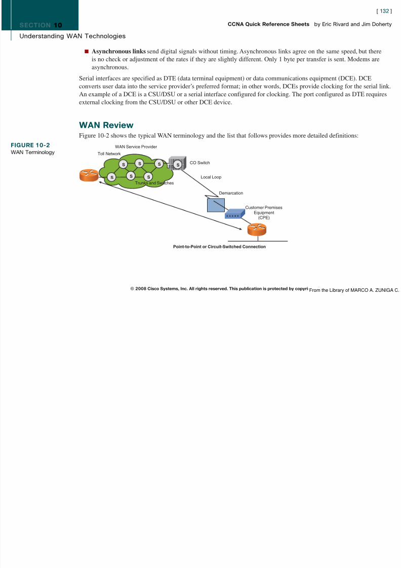
8/12/2019 59811139 CCNA Quick Reference Sheets
http://slidepdf.com/reader/full/59811139-ccna-quick-reference-sheets 132/311
n Asynchronous links send digital signals without timing. Asynchronous links agree on the same speed, but thereis no check or adjustment of the rates if they are slightly different. Only 1 byte per transfer is sent. Modems areasynchronous.
Serial interfaces are specified as DTE (data terminal equipment) or data communications equipment (DCE). DCEconverts user data into the service provider’s preferred format; in other words, DCEs provide clocking for the serial link.An example of a DCE is a CSU/DSU or a serial interface configured for clocking. The port configured as DTE requiresexternal clocking from the CSU/DSU or other DCE device.
WAN ReviewFigure 10-2 shows the typical WAN terminology and the list that follows provides more detailed definitions:
© 2008 Cisco Systems, Inc. All rights reserved. This publication is protected by copyright. Please see page 311 for more details.
FIGURE 10-2WAN Terminology
Point-to-Point or Circuit-Switched Connection
WAN Service Provider
Toll Network
CO Switch
Local Loop
Demarcation
Customer PremisesEquipment
(CPE)
Trunks and Switches
S
S
S
S
S
S
S
From the Library of MARCO A ZUNIGA C
SECTION 10
Understanding WAN Technologies
[ 133 ]
CCNA Quick Reference Sheets by Eric Rivard and Jim Doherty

8/12/2019 59811139 CCNA Quick Reference Sheets
http://slidepdf.com/reader/full/59811139-ccna-quick-reference-sheets 133/311
n Customer premises equipment (CPE): Located on the subscriber’s premises and includes both equipment ownedby the subscriber and devices leased by the service provider.
n Demarcation (or demarc): Marks the point where CPE ends and the local loop begins. It is usually located in the
telecommunications closet.n Local loop (or last mile): The cabling from the demarc into the WAN service provider’s central office.
n Central office (CO): A switching facility that provides a point of presence for WAN service. The central office isthe entry point to the WAN cloud, the exit point from the WAN for called devices, and a switching point for calls.
n Toll network: A collection of trunks inside the WAN cloud.
WAN CablingSeveral ways exist to carry traffic across the WAN. The implementation depends on distance, speed, and the type of service required. Connection speeds typically vary from 56 kbps to T1/E1 (1.544/2.048 Mbps, but can be as high as 10Gbps). WANs use serial communication for long-distance communications.
Layer 2 Encapsulation Protocolsn High-Level Data Link Control (HDLC): The default encapsulation type for Cisco routers on point-to-point dedi-
cated links and circuit-switched connections.
n Point-to-Point Protocol (PPP): Provides connections between devices over several types of physical interfaces,such as asynchronous serial, High-Speed Serial Interface (HSSI), ISDN, and synchronous. PPP works with manynetwork layer protocols, including IP and IPX. PPP can use either Password Authentication Protocol (PAP) orChallenge Handshake Authentication Protocol (CHAP) for authentication.
n X.25/Link Access Procedure, Balanced (LAPB): Defines connections between DTE and DCE for remote terminalaccess. LAPB is a data link layer protocol specified by X.25.
© 2008 Cisco Systems, Inc. All rights reserved. This publication is protected by copyright. Please see page 311 for more details.From the Library of MARCO A ZUNIGA C
SECTION 10
Understanding WAN Technologies
[ 134 ]
CCNA Quick Reference Sheets by Eric Rivard and Jim Doherty
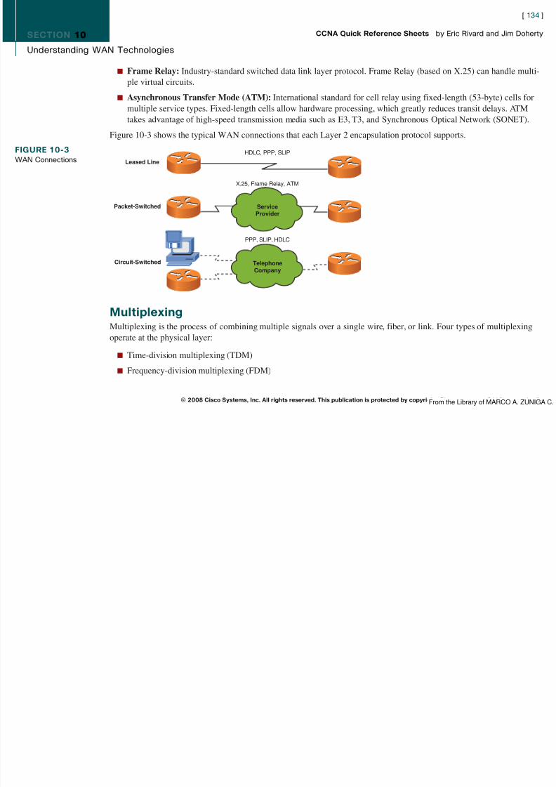
8/12/2019 59811139 CCNA Quick Reference Sheets
http://slidepdf.com/reader/full/59811139-ccna-quick-reference-sheets 134/311
n Frame Relay: Industry-standard switched data link layer protocol. Frame Relay (based on X.25) can handle multi-ple virtual circuits.
n Asynchronous Transfer Mode (ATM): International standard for cell relay using fixed-length (53-byte) cells for
multiple service types. Fixed-length cells allow hardware processing, which greatly reduces transit delays. ATMtakes advantage of high-speed transmission media such as E3, T3, and Synchronous Optical Network (SONET).
Figure 10-3 shows the typical WAN connections that each Layer 2 encapsulation protocol supports.
MultiplexingMultiplexing is the process of combining multiple signals over a single wire, fiber, or link. Four types of multiplexingoperate at the physical layer:
n Time-division multiplexing (TDM)
n Frequency-division multiplexing (FDM)
© 2008 Cisco Systems, Inc. All rights reserved. This publication is protected by copyright. Please see page 311 for more details.
FIGURE 10-3WAN Connections Leased Line
Packet-Switched
Circuit-Switched
HDLC, PPP, SLIP
X.25, Frame Relay, ATM
ServiceProvider
PPP, SLIP, HDLC
TelephoneCompany
From the Library of MARCO A ZUNIGA C
SECTION 10
Understanding WAN Technologies
[ 135 ]
CCNA Quick Reference Sheets by Eric Rivard and Jim Doherty

8/12/2019 59811139 CCNA Quick Reference Sheets
http://slidepdf.com/reader/full/59811139-ccna-quick-reference-sheets 135/311
n Wave-division multiplexing (WDM) and dense WDM (DWDM)
n Statistical-division multiplexing
In TDM, each data channel is allocated bandwidth based on time slots, regardless of whether data is transferred; thus
bandwidth is wasted when there is no data to transfer.
In FDM, information of each data channel is allocated bandwidth based on the signal frequency of the traffic. An exampleof this is FM radio.
In WDM and DWDM, each data channel is allocated bandwidth based on wavelength (inverse of frequency).
In statistical multiplexing, bandwidth is dynamically allocated to data channels.
WAN Communication Link OptionsWAN services are generally leased from service providers on a subscription basis. The following three main types of WAN connections (services) exist:
n Leased line: A leased line (or point-to-point dedicated connection) provides a preestablished connection through theservice provider’s network (WAN) to a remote network. Leased lines provide a reserved connection for the client butare costly. Leased-line connections are typically synchronous serial connections. Figure 10-4 shows an example of aleased line WAN topology.
n Circuit-switched: Circuit switching provides a dedicated circuit path between sender and receiver for the durationof the call. Circuit switching is used for basic telephone service or Integrated Services Digital Network (ISDN).Figure 10-5 shows an example of a circuit-switched WAN topology.
© 2008 Cisco Systems, Inc. All rights reserved. This publication is protected by copyright. Please see page 311 for more details.
FIGURE 10-4Leased-Line WAN
Synchronous Serial
From the Library of MARCO A ZUNIGA C
SECTION 10
Understanding WAN Technologies
[ 136 ]
CCNA Quick Reference Sheets by Eric Rivard and Jim Doherty

8/12/2019 59811139 CCNA Quick Reference Sheets
http://slidepdf.com/reader/full/59811139-ccna-quick-reference-sheets 136/311
n Packet-switched: With packet switching, devices transport packets using virtual circuits (VCs) that provide end-to-end connectivity. Programmed switching devices provide physical connections. Packet headers identify the destina-tion. Packet switching offers leased line–type services over shared lines, but at a much lower cost. Figure 10-6 showsan example of a packet-switched WAN topology.
Enabling the Internet ConnectionAlmost every business today connects to the Internet. It has become common for remote sites to connect to the centraloffice through the Internet using VPNs. Usually, these remote sites connect to the Internet using digital subscriber line(DSL) or a packet-switching technology such as cable.
© 2008 Cisco Systems, Inc. All rights reserved. This publication is protected by copyright. Please see page 311 for more details.
FIGURE 10-5Circuit-Switched WAN
Asynchronous SerialISDN Layer 1
TelephoneCompany
FIGURE 10-6Packet-SwitchedWAN
ServiceProvider
Synchronous Serial
From the Library of MARCO A ZUNIGA C
8/12/2019 59811139 CCNA Quick Reference Sheets
http://slidepdf.com/reader/full/59811139-ccna-quick-reference-sheets 137/311
SECTION 10
Understanding WAN Technologies
[ 138 ]
CCNA Quick Reference Sheets by Eric Rivard and Jim Doherty

8/12/2019 59811139 CCNA Quick Reference Sheets
http://slidepdf.com/reader/full/59811139-ccna-quick-reference-sheets 138/311
DSL StandardsSeveral international DSL standards exist, all of which are supported by DSL providers. They are listed in Table 10-1.
Table 10-1 DSL StandardsDSL Type Speed Distance Limit (ft)
Full-rate ADSL 384 kbps to 8 Mbps downlink and up to 1.024 Mbps uplink 18,000
G.lite 1.544 to 6 Mbps downlink and 640 kbps uplink 18,000
Very high data rate DSL (VDSL) 12.96 to 52.8 Mbps for both downlink and uplink 4,500
ISDN DSL (IDSL) 768 kbps for both downlink and uplink 22,000
High data rate DSL (HDSL) 1.544 to 2.048 Mbps for both downlink and uplink 12,000
G.SHDSL 192 kbps to 2.36 Mbps for both downlink and uplink 28,000
DSL Limitations and AdvantagesAdvantages:
n DSL offers speeds up to and exceeding T1 for a fraction of the cost.
n DSL supports data and voice.
n DSL is an always-on technology.
n DSL service providers can add circuits as needed.
Limitations:
n Availability.
n The telephone company must install DSL equipment.
n DSL has some distance limitations, and the signals cannot be amplified.
© 2008 Cisco Systems, Inc. All rights reserved. This publication is protected by copyright. Please see page 311 for more details.From the Library of MARCO A ZUNIGA C
SECTION 10
Understanding WAN Technologies
[ 139 ]
CCNA Quick Reference Sheets by Eric Rivard and Jim Doherty
8/12/2019 59811139 CCNA Quick Reference Sheets
http://slidepdf.com/reader/full/59811139-ccna-quick-reference-sheets 139/311
CableCable uses the same basic principles as DSL in that the bandwidth needed to accomplish the primary function (providingTV programming) is only a fraction of the available bandwidth on the wire or, in this case, cable.
Like DSL, cable modems provide always-on connectivity. This gives you the convenience of not having to dial up withevery use, but it does make a system more vulnerable to hackers (which is why routers and firewalls should be installedbehind a cable modem). Cable also offers speeds well over those of T1 (some claim up to six times T1 speed). Cablemodems use quadrature amplitude modulation (QAM) to encode digital data into an analog signal to deliver 30 to 40Mbps in one 6-MHz cable channel. A headend facility at the local cable office manages traffic flows and performs thefollowing functions:
n Receives programming from networks
n Converts signals and places them on the proper channel frequency
n Combines all channels into one broadband analog channel
n Broadcasts the combined analog signal to subscribers
Cable Limitations and AdvantagesAdvantages:
n Cable offers very high speeds in both upstream and downstream directions.
n
Cable is fairly widespread in the United States, so access is generally available.n Many cable providers deploy hybrid-fiber coaxial (HFC) cable, which provides greater bandwidth and less noise
than standard coaxial.
© 2008 Cisco Systems, Inc. All rights reserved. This publication is protected by copyright. Please see page 311 for more details.From the Library of MARCO A ZUNIGA C

8/12/2019 59811139 CCNA Quick Reference Sheets
http://slidepdf.com/reader/full/59811139-ccna-quick-reference-sheets 140/311

8/12/2019 59811139 CCNA Quick Reference Sheets
http://slidepdf.com/reader/full/59811139-ccna-quick-reference-sheets 141/311
SECTION 10
Understanding WAN Technologies
NAT T i l
[ 142 ]
CCNA Quick Reference Sheets by Eric Rivard and Jim Doherty

8/12/2019 59811139 CCNA Quick Reference Sheets
http://slidepdf.com/reader/full/59811139-ccna-quick-reference-sheets 142/311
NAT TerminologyTable 10-2 lists the Cisco NAT terminology.
Table 10-2NAT TerminologyName Description
Inside local address The IP address assigned to a host on the inside, private network. Usually a private IP address.
Inside global address A legal routable IP address that represents one or more inside local IP addresses to the outside world.
Outside local address The IP address of an outside host as it appears to the inside, private network. This is usually a privateIP address.
Outside global address The IP address assigned to a host on the outside network by the host’s owner. Usually a routable IP address.
Configuring the DHCP Client and PAT Using SDMTo configure a router to be a DHCP client and accept an IP address from an ISP provider, use the following steps:
Step 1. Log on to the router using SDM. Click the Configure button, and then click the Interfaces and Connectionsbutton. Select the Ethernet (PPPoE or Unencapsulated Routing) option, and click the Create NewConnection button, as shown in Figure 10-9.
Step 2. The WAN Wizard appears. Click the Next button. If your ISP is using PPP over Ethernet (PPPoE), select theEnable PPPoE check box, and then click the Next button. Select the Dynamic (DHCP Client) option and
enter the router’s host name, as shown in Figure 10-10. Click the Next button.
© 2008 Cisco Systems, Inc. All rights reserved. This publication is protected by copyright. Please see page 311 for more details.F th Lib f MARCO A ZUNIGA C
SECTION 10
Understanding WAN Technologies
[ 143 ]
CCNA Quick Reference Sheets by Eric Rivard and Jim Doherty
FIGURE 10 9

8/12/2019 59811139 CCNA Quick Reference Sheets
http://slidepdf.com/reader/full/59811139-ccna-quick-reference-sheets 143/311
© 2008 Cisco Systems, Inc. All rights reserved. This publication is protected by copyright. Please see page 311 for more details.
FIGURE 10-9SDM Router DHCPClient Configuration
F th Lib f MARCO A ZUNIGA C
SECTION 10
Understanding WAN Technologies
[ 144 ]
CCNA Quick Reference Sheets by Eric Rivard and Jim Doherty
FIGURE 10-10

8/12/2019 59811139 CCNA Quick Reference Sheets
http://slidepdf.com/reader/full/59811139-ccna-quick-reference-sheets 144/311
Step 3. Select the Port Address Translation check box and select the inside interface, as shown in Figure 10-11.Click the Next button.
© 2008 Cisco Systems, Inc. All rights reserved. This publication is protected by copyright. Please see page 311 for more details.
FIGURE 10 10SDM WAN Wizard
F th Lib f MARCO A ZUNIGA C
SECTION 10
Understanding WAN Technologies
[ 145 ]
CCNA Quick Reference Sheets by Eric Rivard and Jim Doherty
FIGURE 10-11

8/12/2019 59811139 CCNA Quick Reference Sheets
http://slidepdf.com/reader/full/59811139-ccna-quick-reference-sheets 145/311
Step 4. Verify the configuration and click the Finish button.
Verifying NAT and PAT Configuration
The clear ip nat translation * command clears all dynamic translation tables.The clear ip nat translation inside global-ip local-ip command clears a specific entry from a dynamic inside translation table.
The clear ip nat translation outside local-ip global-ip command clears a specific outside translation address.
The show ip nat translations command lists all active translations.
The show ip nat statistics command shows all translation statistics.
© 2008 Cisco Systems, Inc. All rights reserved. This publication is protected by copyright. Please see page 311 for more details.
FIGURE 10 11SDM WAN WizardAdvanced Options
F th Lib f MARCO A ZUNIGA C
SECTION 10
Understanding WAN Technologies
C fig i g S i l E l ti
[ 146 ]
CCNA Quick Reference Sheets by Eric Rivard and Jim Doherty

8/12/2019 59811139 CCNA Quick Reference Sheets
http://slidepdf.com/reader/full/59811139-ccna-quick-reference-sheets 146/311
Configuring Serial Encapsulation
Configuring HDLCHDLC is a data-link protocol used on synchronous serial data links. HDLC cannot support multiple protocols on a singlelink, because it lacks a mechanism to indicate which protocol it is carrying.
The Cisco version of HDLC uses a proprietary field that acts as a protocol field. This field makes it possible for a singleserial link to accommodate multiple network-layer protocols. Cisco HDLC is a point-to-point protocol that can be usedon leased lines between two Cisco devices. PPP should be used when communicating with non-Cisco devices. Figure 10-12shows the frame format of HDLC.
Because HDLC is the default encapsulation type on serial links, you don’t need to configure HDLC. However, if theencapsulation type has been changed to another protocol, the following command changes the serial interface encapsula-tion back to HDLC:
Router(config-if)# encapsulation hdlc
Configuring PPPAs shown in Figure 10-13, PPP uses a Network Control Protocol (NCP) component to encapsulate multiple protocols andthe Link Control Protocol (LCP) to set up and negotiate control options on the data link.
© 2008 Cisco Systems, Inc. All rights reserved. This publication is protected by copyright. Please see page 311 for more details.
FIGURE 10-12
HDLC Frame
Cisco HDLC
Flag Address Control Proprietary Data FCS Flag
F h Lib f MARCO A ZUNIGA C
SECTION 10
Understanding WAN Technologies
[ 147 ]
CCNA Quick Reference Sheets by Eric Rivard and Jim Doherty
FIGURE 10-13

8/12/2019 59811139 CCNA Quick Reference Sheets
http://slidepdf.com/reader/full/59811139-ccna-quick-reference-sheets 147/311
PPP Configuration OptionsCisco routers using PPP encapsulation include the LCP options shown in Table 10-3.
Table 10-3 PPP Configuration OptionsFeature How It Operates Protocol
Authentication Requires a password; performs PAP, CHAPchallenge handshake
Compression Compresses data at source; reproduces Stacker or Predictordata at destination
Error detection Monitors data dropped on link; avoids Magic Numberframe looping
Multilink Provides load balancing across Multilink Protocol (MP)multiple links
© 2008 Cisco Systems, Inc. All rights reserved. This publication is protected by copyright. Please see page 311 for more details.
FIGURE 10 13Point-to-Point Protocol IP IPX Layer 3 Protocols
IPCP IPXCP Many Others
Network Control Protocol
Network Layer
Data Link Layer
PhysicalLayer
PPP
Authentication, Other OptionsLink Control Protocol
Synchronous or AsynchronousPhysical Media
From the Library of MARCO A. ZUNIGA C.
SECTION 10
Understanding WAN Technologies
Establishing a PPP Session
[ 148 ]
CCNA Quick Reference Sheets by Eric Rivard and Jim Doherty
8/12/2019 59811139 CCNA Quick Reference Sheets
http://slidepdf.com/reader/full/59811139-ccna-quick-reference-sheets 148/311
Establishing a PPP SessionThe three phases of PPP session establishment are described as follows:
1. Link establishment: Each PPP device sends LCP packets to configure and test the link (Layer 2).
2. Authentication phase (optional): If authentication is configured, either PAP or CHAP is used to authenticate thelink. This must take place before the network layer protocol phase can begin (Layer 2).
3. Network layer protocol phase: PPP sends NCP packets to choose and configure one or more network layer proto-cols to be encapsulated and sent over the PPP data link (Layer 3).
Enabling PPPTo enable PPP encapsulation on a serial interface, enter the encapsulation ppp interface command, as follows:
RouterB(config-if)# encapsulation ppp
PPP Authentication ProtocolsThe two methods of authentication on PPP links are as follows:
n Password Authentication Protocol (PAP): The less-secure of the two methods; passwords are sent in clear text andare exchanged only upon initial link establishment.
n Challenge Handshake Authentication Protocol (CHAP): Used upon initial link establishment and periodically tomake sure that the router is still communicating with the same host. CHAP passwords are exchanged as message
digest algorithm 5 (MD5) hash values. CHAP uses a three-way handshake process to perform one-way authentica-tion on a PPP serial interface.
© 2008 Cisco Systems, Inc. All rights reserved. This publication is protected by copyright. Please see page 311 for more details.From the Library of MARCO A. ZUNIGA C.
SECTION 10
Understanding WAN Technologies
Configuring PPP Authentication
[ 149 ]
CCNA Quick Reference Sheets by Eric Rivard and Jim Doherty

8/12/2019 59811139 CCNA Quick Reference Sheets
http://slidepdf.com/reader/full/59811139-ccna-quick-reference-sheets 149/311
Configuring PPP AuthenticationThe three steps to enable PPP authentication on a Cisco router are as follows:
Step 1. Make sure that each router has a host name assigned to it using the hostname command.
Step 2. On each router, define the username of the remote router and the password that both routers will use with theusername remote-router-name password password command.
Step 3. Configure PPP authentication with the ppp authentication {chap | chap pap | pap chap | pap } interfacecommand. (If both PAP and CHAP are enabled, the first method you specify in the command is used. If thepeer suggests the second method or refuses the first method, the second method is used.)
The following commands configure CHAP and PAP for authentication with the password of cisco. The remote router’shost name is RouterA:
RouterB(config)# hostname RouterBRouterB(config)# username RouterA password cisco
RouterB(config)# int s0
RouterB(config-if)# ppp authentication chap pap
Verifying the Serial Encapsulation ConfigurationThe show interface interface-number command shows the encapsulation type configured on the router’s serial interfaceand the LCP and NCP states of an interface if PPP encryption is enabled:
RouterA# show int s0Serial0 is up, line protocol is up
Hardware is HD64570
Internet address is 192.168.1.2/24
MTU 1500 bytes, BW 1544 Kbit, DLY 20000 usec, rely 255/255, load 1/255
Encapsulation PPP, loopback not set, keepalive set (10sec)
© 2008 Cisco Systems, Inc. All rights reserved. This publication is protected by copyright. Please see page 311 for more details.From the Library of MARCO A. ZUNIGA C.
SECTION 10
Understanding WAN Technologies
LCP Open
[ 150 ]
CCNA Quick Reference Sheets by Eric Rivard and Jim Doherty

8/12/2019 59811139 CCNA Quick Reference Sheets
http://slidepdf.com/reader/full/59811139-ccna-quick-reference-sheets 150/311
Open: IPCP, CDPCP
Last input 00:00:02, output 00:00:02, output hang never
Last clearing of “show interface” counters never
Input queue: 0/75/0 (size/max/drops); Total output drops: 0(text omitted)
The IOS debug ppp authentication command shows successful CHAP or PAP authentication.
The debug ppp negotiation command shows PPP-enabled routers performing negotiation.
Frame RelayFrame Relay is a connection-oriented Layer 2 protocol that allows several data connections (virtual circuits) to be multi-
plexed onto a single physical link. Frame Relay relies on upper-layer protocols for error correction. Frame Relay specifiesonly the connection between a router and a service provider’s local access switching equipment.
A connection identifier maps packets to outbound ports on the service provider’s switch. When the switch receives aframe, a lookup table maps the frame to the correct outbound port. The entire path to the destination is determined beforethe frame is sent.
Frame Relay Terminologyn VC (virtual circuit): A logical circuit between two network devices. A VC can be permanent (PVC) or switched
(SVC). PVCs save bandwidth (no circuit establishment or teardown) but can be expensive. SVCs are established ondemand and are torn down when transmission is complete. VC status can be active, inactive, or deleted. Today, mostFrame Relay circuits are PVCs.
© 2008 Cisco Systems, Inc. All rights reserved. This publication is protected by copyright. Please see page 311 for more details.From the Library of MARCO A. ZUNIGA C.
SECTION 10
Understanding WAN Technologies
n DLCI (data-link connection identifier): Identifies the logical connection between two directly connected sets of
[ 151 ]
CCNA Quick Reference Sheets by Eric Rivard and Jim Doherty

8/12/2019 59811139 CCNA Quick Reference Sheets
http://slidepdf.com/reader/full/59811139-ccna-quick-reference-sheets 151/311
( ) g ydevices. The DLCI is locally significant.
n CIR (committed information rate): The minimum guaranteed data transfer rate agreed to by the Frame Relayswitch.
n Inverse ARP: Routers use inverse ARP to discover the network address of a device associated with a VC.
n LMI (Local Management Interface): A signaling standard that manages the connection between the router and theFrame Relay switch. LMIs track and manage keepalive mechanisms, multicast messages, and DLCI status. Routersautosense LMI types by sending a status request to the Frame Relay switch. The router configures itself to match theLMI type response. The three types of LMIs supported by Cisco Frame Relay switches are Cisco (developed byCisco, StrataCom, Northern Telecom, and DEC), ANSI Annex D (ANSI standard T1.617), and Q933a (ITU-T Q.933Annex A).
n FECN (forward explicit congestion notification ): A message sent to a destination device when a Frame Relayswitch senses congestion in the network.
n BECN (backward explicit congestion notification): A message sent to a source router when a Frame Relay switchrecognizes congestion in the network. A BECN message requests a reduced data transmission rate.
ATM and Cell SwitchingAsynchronous Transfer Mode (ATM) was originally developed as a high-speed public WAN transport for voice, video,
and data. ATM was later modified by the ATM Forum to include transport over private networks.ATM networks are composed of ATM switches interconnected by point-to-point ATM links. The links connecting theswitches come in two forms: User-Network Interfaces (UNI), which connect ATM endpoints to ATM switches, andNetwork Node Interfaces (NNI), which connect ATM switches.
© 2008 Cisco Systems, Inc. All rights reserved. This publication is protected by copyright. Please see page 311 for more details.From the Library of MARCO A. ZUNIGA C.

8/12/2019 59811139 CCNA Quick Reference Sheets
http://slidepdf.com/reader/full/59811139-ccna-quick-reference-sheets 152/311

8/12/2019 59811139 CCNA Quick Reference Sheets
http://slidepdf.com/reader/full/59811139-ccna-quick-reference-sheets 153/311
SECTION 11
RIP Routing
Classes of Routing Protocols
[ 154 ]
CCNA Quick Reference Sheets by Eric Rivard and Jim Doherty

8/12/2019 59811139 CCNA Quick Reference Sheets
http://slidepdf.com/reader/full/59811139-ccna-quick-reference-sheets 154/311
C asses o out g otoco sAs mentioned in Chapter 8, “Exploring the Functions of Routing,” three classes or methods of routing protocols exist:
n Distance vector
n Link-state
n Advanced distance vector (also called balanced hybrid)
Routing Ranges with Administrative DistanceSeveral routing protocols can be used at the same time in the same network. When more than a single source of routinginformation exists for the same destination prefix, the source with the lowest administrative distance value is preferred.
Table 11-1 shows the default administrative distance of learned routes.
Table 11-1 ADRoute Source Default Distance Values
Connected interface 0
Static route 1
EIGRP 5
BGP 20
Internal EIGRP 90IGRP 100
IS-IS 115
RIP 120
EGP 140
© 2008 Cisco Systems, Inc. All rights reserved. This publication is protected by copyright. Please see page 311 for more details.
continues
From the Library of MARCO A. ZUNIGA C.
SECTION 11
RIP Routing
Table 11-1 AD continued
[ 155 ]
CCNA Quick Reference Sheets by Eric Rivard and Jim Doherty
8/12/2019 59811139 CCNA Quick Reference Sheets
http://slidepdf.com/reader/full/59811139-ccna-quick-reference-sheets 155/311
Route Source Default Distance Values
ODR 160
External EIGRP 170
Internal BGP 200
Unknown 255
Classless Versus Classful RoutingClassless routing protocols include subnet mask information in routing advertisements and support variable-length subnetmask (VLSM). In classless routing, summarization is controlled manually. RIP v2, OSPF, IS-IS, and EIGRP are classlessrouting protocols.
Classful routing protocols do not include the subnet mask in routing advertisements. As a result, all subnetworks of thesame major network must use the same subnet mask. Routers using classful routing protocols automatically perform routesummarization across network boundaries. RIPv1 is an example of a classful routing protocol.
The ip classless command prevents a router from dropping packets for an unknown subnetwork of a directly attachednetwork if a default route is configured. The ip classless command is enabled by default.
Distance Vector Route SelectionRouters using distance vector–based routing share routing table information with each other. This method of updating iscalled “routing by rumor.” Each router receives updates from its direct neighbor. In Figure 11-2, Router B shares informa-tion with Routers A and C. Router C shares routing information with Routers B and D. In this case, the routing information
© 2008 Cisco Systems, Inc. All rights reserved. This publication is protected by copyright. Please see page 311 for more details.From the Library of MARCO A. ZUNIGA C.
SECTION 11
RIP Routing
is distance vector metrics (such as the number of hops). Each router increments the metrics as they are passed on (incre-
[ 156 ]
CCNA Quick Reference Sheets by Eric Rivard and Jim Doherty

8/12/2019 59811139 CCNA Quick Reference Sheets
http://slidepdf.com/reader/full/59811139-ccna-quick-reference-sheets 156/311
menting hop count, for example).
Distance accumulation keeps track of the routing distance between any two points in the network, but the routers do notknow the exact topology of an internetwork.
How Information Is Discovered with Distance VectorsNetwork discovery is the process of learning about nondirectly connected destinations. As the network discovery
proceeds, routers accumulate metrics and learn the best paths to various destinations. In Figure 11-3, each directlyconnected network has a distance of 0. Router A learns about other networks based on information it receives fromRouter B. Router A increments the distance metric for any route learned by Router B. For example, Router B knowsabout the networks to Router C, which is directly connected. Router B then shares this information with Router A, whichincrements the distance to these networks by 1.
© 2008 Cisco Systems, Inc. All rights reserved. This publication is protected by copyright. Please see page 311 for more details.
FIGURE 11-2Distance Vector
Routing Protocols
Vector—In Which Direction?Distance—How Far?
D
AC
B
D AC B
RoutingTable
RoutingTable
RoutingTable
RoutingTable
From the Library of MARCO A. ZUNIGA C.
SECTION 11
RIP Routing
[ 157 ]
CCNA Quick Reference Sheets by Eric Rivard and Jim Doherty
FIGURE 11-3 10.1.0.0 10.2.0.0 10.3.0.0 10.4.0.0

8/12/2019 59811139 CCNA Quick Reference Sheets
http://slidepdf.com/reader/full/59811139-ccna-quick-reference-sheets 157/311
During updates, routing loops can occur if the network has inconsistent routing entries. Slow convergence on a newconfiguration is one cause of this phenomenon. The network is converged when all routers have consistent routing tables.
Routing MetricsRouting protocols use their own rules and metrics to build and update routing tables automatically. Routing metrics aremeasures of path desirability. Different protocols use different metrics. Some common metrics are as follows:
n Bandwidth: The link’s data capacity.
n Delay: The time required to move the packet from the current router to the destination. This depends on bandwidth,port delays, congestion, and distance.
n Load: The amount of activity on the interface.
n Reliability: The error rate of each network link.
n Hop count: The number of routers the packet must travel through before reaching the destination.
n Cost: An arbitrary value based on bandwidth, expense, and other metrics assigned by the administrator.
© 2008 Cisco Systems, Inc. All rights reserved. This publication is protected by copyright. Please see page 311 for more details.
Distance VectorRoute-LearningProcess
E0 S0 S0 S1 S0 E0
10.1.0.0 E0 010.2.0.0 S0 010.3.0.0 S0 110.4.0.0 S0 2
Routing Table Routing Table10.2.0.0 S0 010.3.0.0 S1 010.4.0.0 S1 110.1.0.0 S0 1
Routing Table10.3.0.0 S0 010.4.0.0 E0 010.2.0.0 S0 110.1.0.0 S0 2
A CB
From the Library of MARCO A. ZUNIGA C.
SECTION 11
RIP Routing
Techniques to Eliminate Routing Loops
[ 158 ]
CCNA Quick Reference Sheets by Eric Rivard and Jim Doherty

8/12/2019 59811139 CCNA Quick Reference Sheets
http://slidepdf.com/reader/full/59811139-ccna-quick-reference-sheets 158/311
Techniques to Eliminate Routing LoopsA routing loop prevents some packets from being properly routed because of incorrect routing information circulating inthe network. Routing loops usually occur when unreachable networks are incorrectly replaced by older routing informa-
tion from other devices in the network. Routing protocols have some mechanisms to prevent routing loops.
Split HorizonSplit horizon is one way to eliminate routing loops and speed convergence. The idea behind split horizon is that it isnever useful to send information about a route back in the direction from which the update came. If the router has novalid alternative path to the network, it is considered inaccessible. Split horizon also eliminates unnecessary routingupdates, thus speeding convergence. In Figure 11-4, Router A, using split horizon, will not send route advertisements thatcontain routes learned on serial interface 0 out serial interface 0.
Hold-Down TimersHold-down timers dictate that when a route is invalid, no new route with the same or a worse metric will be accepted forthe same destination for some period of time. This allows network updates to propagate throughout the network.
© 2008 Cisco Systems, Inc. All rights reserved. This publication is protected by copyright. Please see page 311 for more details.
FIGURE 11-4Split Horizon
10.1.0.0 10.2.0.0 10.3.0.0 10.4.0.0
E0 S0 S0 S1 S0 E0
10.1.0.0 E0 010.2.0.0 S0 010.3.0.0 S0 110.4.0.0 S0 2
Routing Table Routing Table10.2.0.0 S0 010.3.0.0 S1 010.4.0.0 S1 110.1.0.0 S0 1
Routing Table10.3.0.0 S0 010.4.0.0 E0 010.2.0.0 S0 110.1.0.0 S0 2
X X
A CB
From the Library of MARCO A. ZUNIGA C.
SECTION 11
RIP Routing
Route poisoning (part of split horizon) also eliminates routing loops caused by inconsistent updates. Route poisoningb i ll “ h bl ” d l k h bl ( i h ld d i ) il h k h d
[ 159 ]
CCNA Quick Reference Sheets by Eric Rivard and Jim Doherty

8/12/2019 59811139 CCNA Quick Reference Sheets
http://slidepdf.com/reader/full/59811139-ccna-quick-reference-sheets 159/311
basically sets a route to “unreachable” and locks the table (using hold-down timers) until the network has converged.
Route PoisoningIn Figure 11-5, when network 10.4.0.0 goes down, Router C “poisons” its link to network 10.4.0.0 by sending an updatefor network 10.4.0.0 that indicates it has an infinite metric and a hop count of 16 (that is, it is unreachable). The routeradvertises the poisoned route to its neighbors.
Router C is no longer susceptible to incorrect updates about network 10.4.0.0 coming from neighboring routers that mightclaim to have a valid alternative path. After the hold-down timer expires (which is just longer than the time to conver-gence), Router C begins accepting updates again.
Poison ReverseIn Figure 11-6, when Router B sees the metric to 10.4.0.0 jump to infinity, it sends a return message (overriding splithorizon) called a poison reverse back to Router C, stating that network 10.4.0.0 is inaccessible. This message ensures thatall routers on that segment have received information about the poisoned route.
© 2008 Cisco Systems, Inc. All rights reserved. This publication is protected by copyright. Please see page 311 for more details.
FIGURE 11-5Routing Poisoning
C
10.1.0.0 10.2.0.0 10.3.0.0 10.4.0.0
E0 S0 S0 S1 S0 E0
10.1.0.0 E0 010.2.0.0 S0 010.3.0.0 S0 110.4.0.0 S0 2
Routing Table Routing Table10.2.0.0 S0 010.3.0.0 S1 010.4.0.0 S1 110.1.0.0 S0 1
Routing Table10.3.0.0 S0 010.4.0.0 E0 Down10.2.0.0 S0 110.1.0.0 S0 2
XA CB
From the Library of MARCO A. ZUNIGA C.
SECTION 11
RIP Routing
[ 160 ]
CCNA Quick Reference Sheets by Eric Rivard and Jim Doherty
FIGURE 11-6P i R
10.1.0.0 10.2.0.0 10.3.0.0 10.4.0.0

8/12/2019 59811139 CCNA Quick Reference Sheets
http://slidepdf.com/reader/full/59811139-ccna-quick-reference-sheets 160/311
Triggered UpdatesAlso known as flash updates, triggered updates are routing updates sent immediately out a router’s interface when it
notices that a directly connected subnet has changed state.
RIPRIP is a true distance vector routing protocol that sends its complete routing table out all active interfaces every 30seconds. RIP is subject to the split horizon rule.
RIP uses a hop count as its metric to determine the best path to a remote network. The maximum allowable hop count is15; thus a hop count of 16 is unreachable.
Two versions of RIP exist: version 1 and version 2.
RIP can load-balance over as many as 16 equal-cost paths; the default is 4.
© 2008 Cisco Systems, Inc. All rights reserved. This publication is protected by copyright. Please see page 311 for more details.
Poison ReverseE0 A S0 S0 S1 S0 E0
CB
10.1.0.0 E0 010.2.0.0 S0 010.3.0.0 S0 110.4.0.0 S0 2
Routing Table Routing Table10.2.0.0 S0 010.3.0.0 S1 010.4.0.0 S110.1.0.0 E1 2
Routing Table10.3.0.0 S0 010.4.0.0 S0 Infinity10.2.0.0 S0 110.1.0.0 S0 2
PoisonReverse
Possibly Down
From the Library of MARCO A. ZUNIGA C.
SECTION 11
RIP Routing
RIPv1 and RIPv2 Comparisons
[ 161 ]
CCNA Quick Reference Sheets by Eric Rivard and Jim Doherty

8/12/2019 59811139 CCNA Quick Reference Sheets
http://slidepdf.com/reader/full/59811139-ccna-quick-reference-sheets 161/311
RIP version 1 is a classful protocol, meaning that it does not send its subnet mask in routing updates. As a result, RIPv1does not support variable-length subnet mask.
RIP version 2 is a classless protocol that supports VLSM and sends its subnet mask in routing updates.
RIP version 2 also sends routing updates through multicast. RIP v1 broadcasts updates. RIP v2 also supports manualroute summarization and authentication. RIP v1 does not.
RIP TimersRIP uses four timers to regulate performance and route updates:
n Route update timer:The time between router updates. Default is 30 seconds.
n Route invalid timer: The time that must expire before a route becomes invalid. Default is 180 seconds.
n Route hold-down timer: If RIP receives an update with a hop count higher than the metric recording in the routingtable, RIP goes into a hold-down for 180 seconds.
n Route flush timer: The time from when a route becomes invalid to when it is removed from the routing table.Default is 240 seconds.
Configuring and Verifying RIPThe commands to enable RIP on a Cisco router are as follows:
n router rip global command
n network connected-network-address configuration command
© 2008 Cisco Systems, Inc. All rights reserved. This publication is protected by copyright. Please see page 311 for more details.From the Library of MARCO A. ZUNIGA C.

8/12/2019 59811139 CCNA Quick Reference Sheets
http://slidepdf.com/reader/full/59811139-ccna-quick-reference-sheets 162/311
SECTION 11
RIP Routing
Displaying the Routing Table
[ 163 ]
CCNA Quick Reference Sheets by Eric Rivard and Jim Doherty

8/12/2019 59811139 CCNA Quick Reference Sheets
http://slidepdf.com/reader/full/59811139-ccna-quick-reference-sheets 163/311
The show ip route command, as follows, displays the Cisco routing table’s contents:
RouterA# show ip route
Codes: C - connected, S - static, I - IGRP, R - RIP, M - mobile,B - BGPD - EIGRP, EX - EIGRP external, O - OSPF, IA - OSPF interarea
N1 - OSPF NSSA external type 1, N2 - OSPF NSSA external type 2
E1 - OSPF external type 1, E2 - OSPF external type 2, E - EGP
i - IS-IS, L1 - IS-IS level-1, L2 - IS-IS level-2, * - candidate default
U - per-user static route, o - ODR
Gateway of last resort is 192.168.1.1 to network 0.0.0.0
1.0.0.0/32 is subnetted, 1 subnets
C 1.1.1.1 is directly connected, Loopback0
R 192.168.0.0/24 [120/1] via 192.168.1.1, 00:00:21, Serial0
C 192.168.1.0/24 is directly connected, Serial0
C 192.168.2.0/24 is directly connected, Ethernet0R* 0.0.0.0/0 [120/1] via 192.168.1.1, 00:00:21, Serial0
The [120/1] indicates that 120 is the AD and 1 is the number of hops to the remote network. R indicates that RIP haslearned paths to networks 192.168.0.0/24 and 0.0.0.0/0.
Troubleshooting RIPThe debug ip rip command displays routing updates as they are sent and received, thus allowing you to troubleshoot RIP.
© 2008 Cisco Systems, Inc. All rights reserved. This publication is protected by copyright. Please see page 311 for more details.From the Library of MARCO A. ZUNIGA C.

8/12/2019 59811139 CCNA Quick Reference Sheets
http://slidepdf.com/reader/full/59811139-ccna-quick-reference-sheets 164/311
SECTION 12
Managing Your Network Environment
Implementation of CDP
[ 165 ]
CCNA Quick Reference Sheets by Eric Rivard and Jim Doherty
8/12/2019 59811139 CCNA Quick Reference Sheets
http://slidepdf.com/reader/full/59811139-ccna-quick-reference-sheets 165/311
n cdp enable enables CDP on an interface.
n no cdp enable disables CDP on an interface.
n cdp run allows other CDP devices to get information about your device.n no cdp run disables CDP on a device.
n show cdp displays the CDP output.
n show cdp neighbors displays the CDP updates received on the local interfaces and information about CDP neigh-bors. For each CDP neighbor, the following is displayed:
n Neighbor device ID
n Local interface
n Holdtime value in seconds
n Neighbor device capability code (router, switch)
n Neighbor hardware platform
n Neighbor remote port ID
n show cdp neighbors detail displays updates received on the local interfaces. This command displays the same infor-mation as the show cdp entry * command. The show cdp neighbors detail command shows the same information
as sh cdp neighbors , in addition to the network layer address of the CDP neighbor.
© 2008 Cisco Systems, Inc. All rights reserved. This publication is protected by copyright. Please see page 311 for more details.From the Library of MARCO A. ZUNIGA C.
SECTION 12
Managing Your Network Environment
n show cdp entry displays the following information about neighboring devices:
[ 166 ]
CCNA Quick Reference Sheets by Eric Rivard and Jim Doherty

8/12/2019 59811139 CCNA Quick Reference Sheets
http://slidepdf.com/reader/full/59811139-ccna-quick-reference-sheets 166/311
n Neighbor device ID
n Layer 3 protocol information
n Device platform
n Device capabilities
n Local interface type and outgoing remote port ID
n Holdtime value in seconds
n Cisco IOS Software type and release
n show cdp traffic displays information about interface traffic.
n show cdp interface displays interface status and configuration information.
Managing Router Startup and ConfigurationWhen a router is booted up, it goes through the following sequence:
1. The router checks its hardware with a power-on self test (POST).
2. The router loads a bootstrap code.
3. The Cisco IOS Software is located and loaded using the information in the bootstrap code.4. The configuration is located and loaded.
© 2008 Cisco Systems, Inc. All rights reserved. This publication is protected by copyright. Please see page 311 for more details.From the Library of MARCO A. ZUNIGA C.
SECTION 12
Managing Your Network Environment
Router Components
[ 167 ]
CCNA Quick Reference Sheets by Eric Rivard and Jim Doherty
8/12/2019 59811139 CCNA Quick Reference Sheets
http://slidepdf.com/reader/full/59811139-ccna-quick-reference-sheets 167/311
The major router components are as follows:
n RAM: Random-access memory contains key software (IOS).
n ROM: Read-only memory contains startup microcode.
n NVRAM: Nonvolatile RAM stores the configuration.
n Configuration register: Controls the bootup method.
n Interfaces: The interface is the physical connection to the external devices. Physical connections can include TokenRing and FDDI.
n Flash memory: Flash contains the Cisco IOS Software image. Some routers run the IOS image directly from flashand do not need to transfer it to RAM.
ROM FunctionsROM contains the startup microcode and consists of the following four areas:
n Bootstrap code: Brings the router up during initialization. Reads the configuration register to determine howto boot.
n POST: Tests the basic function of the router hardware and determines the hardware present.
nROMMON: A low-level operating system normally used for manufacturing, testing, troubleshooting, and passwordrecovery.
n Mini Cisco IOS Software file: Loads a new Cisco IOS image into flash memory from a TFTP server.
© 2008 Cisco Systems, Inc. All rights reserved. This publication is protected by copyright. Please see page 311 for more details.From the Library of MARCO A. ZUNIGA C.
SECTION 12
Managing Your Network Environment
How a Cisco Device Locates and Loads IOS Images
[ 168 ]
CCNA Quick Reference Sheets by Eric Rivard and Jim Doherty

8/12/2019 59811139 CCNA Quick Reference Sheets
http://slidepdf.com/reader/full/59811139-ccna-quick-reference-sheets 168/311
The bootstrap code locates and loads the Cisco IOS image. It does this by first looking at the configuration register. Thedefault value for the configuration register is 0x2102. Changing the configuration register changes the location of the IOSload.
If the configuration register’s fourth character is from 0x2 to 0xF, the bootstrap parses the startup-config file in NVRAMfrom the boot system command that specifies the name and location of the Cisco IOS Software image to load.
After the IOS is loaded, the router must be configured. Configurations in NVRAM are executed. If one does not exist inNVRAM, the router initiates an auto-install or setup utility. The auto-install routine attempts to download a configurationfile from a TFTP server.
The Configuration RegisterThe config register includes information that specifies where to locate the Cisco IOS Software image.
Before changing the configuration register, use the show version command to determine the current image. The last linecontains the register value. Changing this value changes the location of the IOS load (and many other things). A reloadcommand must be used for the new configuration to be set. The register value is checked only during the boot process.
Table 12-1 shows the configuration register values and meanings.
Table 12-1 Configuration Register ValuesConfiguration Register Boot Field Value Meaning
0x0 Use ROM monitor mode (manually boot using the boot command)
0x1 Automatically boot from ROM (provides IOS subset)
0x2 to 0xF Examine NVRAM for boot system commands (0x2 is the default if router has flash)
© 2008 Cisco Systems, Inc. All rights reserved. This publication is protected by copyright. Please see page 311 for more details.From the Library of MARCO A. ZUNIGA C.
SECTION 12
Managing Your Network Environment
The show version command verifies changes in the configuration register setting.
[ 169 ]
CCNA Quick Reference Sheets by Eric Rivard and Jim Doherty

8/12/2019 59811139 CCNA Quick Reference Sheets
http://slidepdf.com/reader/full/59811139-ccna-quick-reference-sheets 169/311
The show flash command displays contents in flash memory, including the image filenames and sizes.
The show running-config command shows the current running configuration in RAM.
The show startup-config command shows the configuration file saved in NVRAM. This is the configuration that will beused if the router is reloaded and the running-config is not saved.
Managing IOS ImagesThe Cisco IOS File System (IFS) feature provides an interface to the router file systems. The uniform resource locator(URL) convention allows you to specify files on network devices.
URL prefixes for Cisco network devices are as follows:n bootflash: Boot flash memory
n flash: Available on all platforms
n flh: Flash load helper log files
n ftp: File Transfer Protocol (FTP) network server
n nvram: NVRAM
n
rcp: Remote Copy Protocol (RCP) network servern slot0: First PCMCIA flash memory card
n slot1: Second PCMCIA flash memory card
n system: Contains the system memory and the running configuration
n tftp: Trivial File Transfer Protocol (TFTP) network server
© 2008 Cisco Systems, Inc. All rights reserved. This publication is protected by copyright. Please see page 311 for more details.From the Library of MARCO A. ZUNIGA C.
SECTION 12
Managing Your Network Environment
Backing Up and Upgrading IOS Imageswg ro a# show flash
[ 170 ]
CCNA Quick Reference Sheets by Eric Rivard and Jim Doherty

8/12/2019 59811139 CCNA Quick Reference Sheets
http://slidepdf.com/reader/full/59811139-ccna-quick-reference-sheets 170/311
wg_ro_a# show flash
wg_ro_a# copy flash tftpwg_ro_a# copy tftp flash
When using the copy flash command, you must enter the IP address of the remote host and the name of the source anddestination system image file.
The router prompts you for the IP address of the remote host and the name of the source and destination system image file.
Cisco IOS copy CommandAs shown in Figure 12-2, the copy commands are used to move configuration from one component or device to another.The syntax is as follows:
copy object source destination
For example:
copy running-config startup-config
© 2008 Cisco Systems, Inc. All rights reserved. This publication is protected by copyright. Please see page 311 for more details.
FIGURE 12-2IOS copy Command
RAMcopy running startup
copy startup running ( merge )
NVRAM
config term (merge )
copy tftp run(merge )
copy run tftp
TFTPserver
copy tftp start
copy start tftp
erasestart
Blank 000000000000
Console
Config ConfigNOTEWhen a configuration iscopied into RAM, itmerges with the existingconfiguration in RAM. Itdoes not overwrite theexisting configuration. InCisco IOS Release 12.3Tand later, the configurereplace command allowsyou to overwrite therunning configuration.
From the Library of MARCO A. ZUNIGA C.

8/12/2019 59811139 CCNA Quick Reference Sheets
http://slidepdf.com/reader/full/59811139-ccna-quick-reference-sheets 171/311
SECTION 1
Implementing VLANs and Trunks
ICND2
[ 172 ]
CCNA Quick Reference Sheets by Eric Rivard and Jim Doherty

8/12/2019 59811139 CCNA Quick Reference Sheets
http://slidepdf.com/reader/full/59811139-ccna-quick-reference-sheets 172/311
Part I: LAN Switching
Section 1Implementing VLANS and Trunks
VLANsThe virtual LAN (VLAN) organizes physically separate users into the same broadcast domain. The use of VLANs
improves performance, security, and flexibility. The use of VLANs also decreases the cost of arranging users, because noextra cabling is required.
VLAN CharacteristicsVLANs allow logically defined user groups rather than user groups defined by their physical locations. For example, youcan arrange user groups such as accounting, engineering, and finance, rather than everyone on the first floor, everyone onthe second floor, and so on.
n VLANs define broadcast domains that can span multiple LAN segments.n VLANs improve segmentation, flexibility, and security.
n VLAN segmentation is not bound by the physical location of users.
© 2008 Cisco Systems, Inc. All rights reserved. This publication is protected by copyright. Please see page 311 for more details.From the Library of MARCO A. ZUNIGA C.
SECTION 1
Implementing VLANs and Trunks
n Each switch port can be assigned to an access VLAN, a voice VLAN, or a trunk.
n Ports assigned to the same VLAN share broadcasts and are in the same broadcast domain
[ 173 ]
CCNA Quick Reference Sheets by Eric Rivard and Jim Doherty

8/12/2019 59811139 CCNA Quick Reference Sheets
http://slidepdf.com/reader/full/59811139-ccna-quick-reference-sheets 173/311
n Ports assigned to the same VLAN share broadcasts and are in the same broadcast domain.
n A VLAN can exist on one or several switches.
Figure 1-1 shows a VLAN design. Note that VLANs are defined by user functions rather than locations.
© 2008 Cisco Systems, Inc. All rights reserved. This publication is protected by copyright. Please see page 311 for more details.
FIGURE 1-1VLAN Design
3rd Floor
2nd Floor
1s t Floor
S ALES HR EN G
From the Library of MARCO A. ZUNIGA C.

8/12/2019 59811139 CCNA Quick Reference Sheets
http://slidepdf.com/reader/full/59811139-ccna-quick-reference-sheets 174/311

8/12/2019 59811139 CCNA Quick Reference Sheets
http://slidepdf.com/reader/full/59811139-ccna-quick-reference-sheets 175/311
SECTION 1
Implementing VLANs and Trunks
How VTP WorksWhenever a change occurs in the VLAN database the VTP server increments its configuration revision number and then
[ 176 ]
CCNA Quick Reference Sheets by Eric Rivard and Jim Doherty

8/12/2019 59811139 CCNA Quick Reference Sheets
http://slidepdf.com/reader/full/59811139-ccna-quick-reference-sheets 176/311
Whenever a change occurs in the VLAN database, the VTP server increments its configuration revision number and thenadvertises the new revision throughout the VTP domain. A VTP domain is one or more interconnected switches that sharethe same VTP environment. When a switch receives the VTP advertisement, it overwrites its configuration with the newinformation if the new revision number is higher than the one it already has. If the revision number is the same, theswitch ignores the advertisement. If the revision number is lower, the switch replies with the more up-to-date revisionnumber. VTP cannot cross a Layer 3 boundary.
VTP ExampleIn Figure 1-3, the VTP server notifies all switches in its VTP domain that a new VLAN, named “ICND,” has been added.The server advertises VLAN configuration information to maintain domain consistency.
© 2008 Cisco Systems, Inc. All rights reserved. This publication is protected by copyright. Please see page 311 for more details.
FIGURE 1-3Advertising VLANConfigurationInformation
VTP Domain "ICND"
3. Sync to the latest vlan information
1."new vlan added"
2
From the Library of MARCO A. ZUNIGA C.
SECTION 1
Implementing VLANs and Trunks
VTP ModesA Catalyst switch can operate in three different modes: server client or transparent The default mode is server mode
[ 177 ]
CCNA Quick Reference Sheets by Eric Rivard and Jim Doherty

8/12/2019 59811139 CCNA Quick Reference Sheets
http://slidepdf.com/reader/full/59811139-ccna-quick-reference-sheets 177/311
A Catalyst switch can operate in three different modes: server, client, or transparent. The default mode is server mode.VLAN configurations are not advertised until a management domain name is specified or learned. Following are the VTPmodes:
n Server: Switch can add, delete, and modify VLANs and other configuration parameters for the VTP domain.
n Client: Switch cannot create, delete, or modify VLANs. Transmits and receives VTP updates over trunk links.
n Transparent: Switch does not participate in the VTP domain. Switch can add, delete, and modify VLANs locally. InVTP version 2, transparent switches forward VTP advertisements they receive.
VLAN Database
VLAN information is stored in a file located in flash called vlan.dat. If this file is deleted, all switch VLAN informationis deleted.
VTP AdvertisementsVTP advertisements are only sent over trunk links. They are flooded over the native VLAN (VLAN1 by default) everyfive minutes or whenever a change occurs. VTP advertisements include
n VTP domain name
n VTP configuration revision numbern Update identity and update timestamp
n Message digest algorithm 5 (MD5) VLAN configuration
n Frame format
n VLAN ID, name, type, and state
© 2008 Cisco Systems, Inc. All rights reserved. This publication is protected by copyright. Please see page 311 for more details.From the Library of MARCO A. ZUNIGA C.
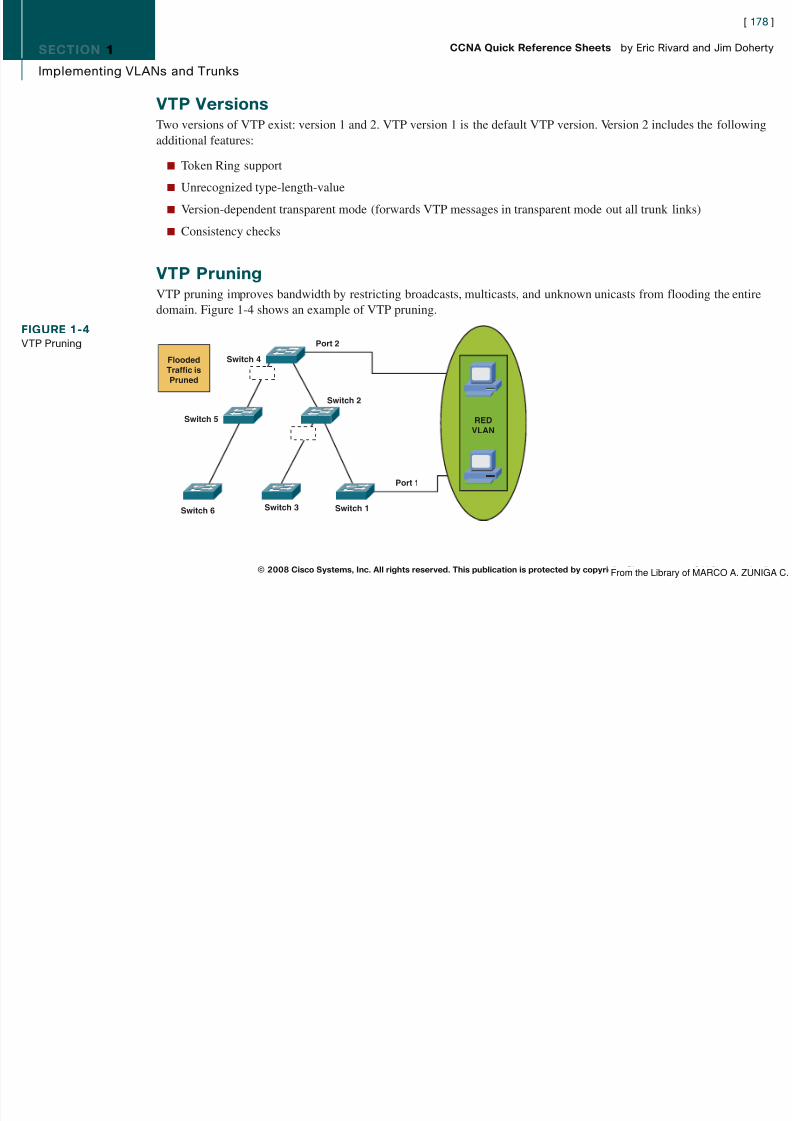
8/12/2019 59811139 CCNA Quick Reference Sheets
http://slidepdf.com/reader/full/59811139-ccna-quick-reference-sheets 178/311
SECTION 1
Implementing VLANs and Trunks
By default, a trunk carries traffic for all VLANs in the VTP management domain. With VTP pruning enabled, updatetraffic from station A is not forwarded to switches 3, 5, and 6, because traffic for the red VLAN has been pruned on the
[ 179 ]
CCNA Quick Reference Sheets by Eric Rivard and Jim Doherty

8/12/2019 59811139 CCNA Quick Reference Sheets
http://slidepdf.com/reader/full/59811139-ccna-quick-reference-sheets 179/311
links indicated on switches 2 and 4.
Default VTP ConfigurationThe default VTP configuration on a Catalyst 2960 switch is as follows:
n VTP domain: Null
n VTP mode: Server
n VTP version: Version 1
n VTP password: None
n VTP pruning: Disabled
Configuring VTP, VLANs, and TrunksThe steps to configure VLANs on a Catalyst 2960 switch are as follows:
Step 1. Configure VTP.
Step 2. Add VLANs and assign port membership modes.
Step 3. Define trunks.
© 2008 Cisco Systems, Inc. All rights reserved. This publication is protected by copyright. Please see page 311 for more details.From the Library of MARCO A. ZUNIGA C.
SECTION 1
Implementing VLANs and Trunks
VTP Commandvtp [ mode {server | client | transparent }] [ domain domain-name ] [ password password ] [ pruning {enable | dis-
[ 180 ]
CCNA Quick Reference Sheets by Eric Rivard and Jim Doherty
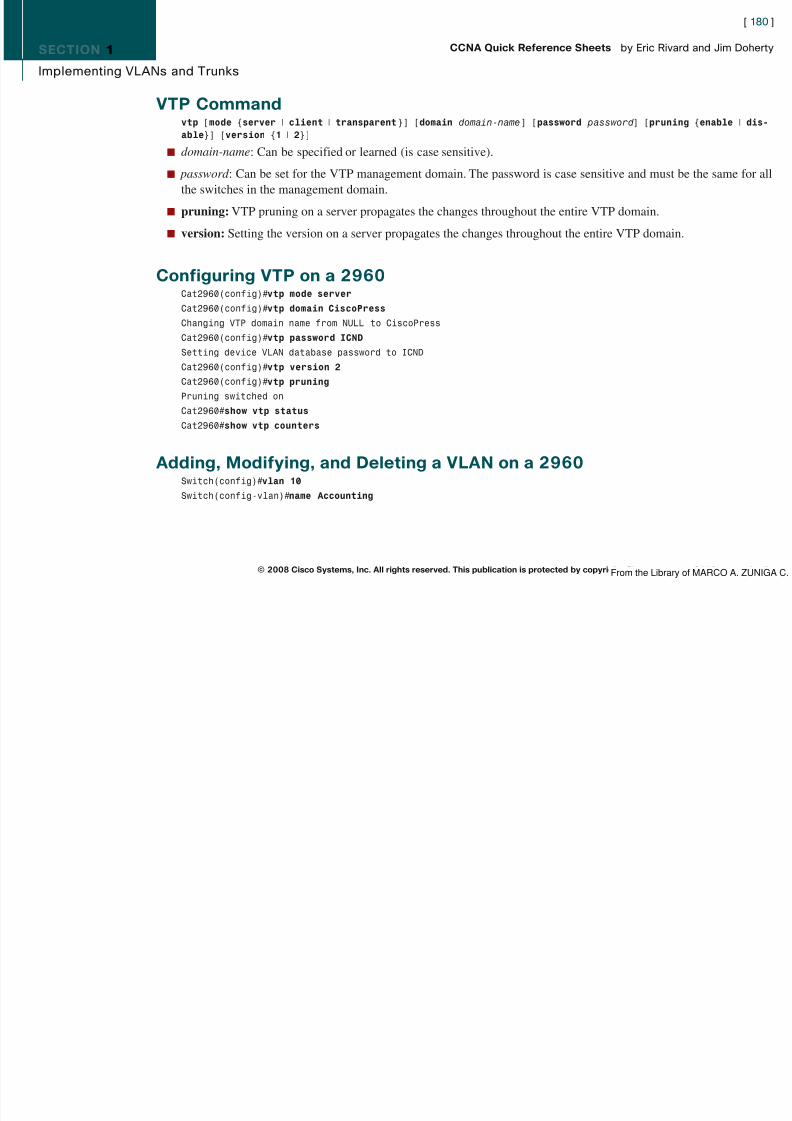
8/12/2019 59811139 CCNA Quick Reference Sheets
http://slidepdf.com/reader/full/59811139-ccna-quick-reference-sheets 180/311
able }] [ version {1 | 2 }]
n domain-name : Can be specified or learned (is case sensitive).
n password : Can be set for the VTP management domain. The password is case sensitive and must be the same for allthe switches in the management domain.
n pruning: VTP pruning on a server propagates the changes throughout the entire VTP domain.
n version: Setting the version on a server propagates the changes throughout the entire VTP domain.
Configuring VTP on a 2960Cat2960(config)# vtp mode server
Cat2960(config)# vtp domain CiscoPressChanging VTP domain name from NULL to CiscoPress
Cat2960(config)# vtp password ICND
Setting device VLAN database password to ICND
Cat2960(config)# vtp version 2Cat2960(config)# vtp pruningPruning switched on
Cat2960# show vtp status
Cat2960# show vtp counters
Adding, Modifying, and Deleting a VLAN on a 2960Switch(config)# vlan 10
Switch(config-vlan)# name Accounting
© 2008 Cisco Systems, Inc. All rights reserved. This publication is protected by copyright. Please see page 311 for more details.From the Library of MARCO A. ZUNIGA C.
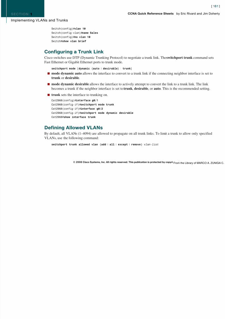
8/12/2019 59811139 CCNA Quick Reference Sheets
http://slidepdf.com/reader/full/59811139-ccna-quick-reference-sheets 181/311
SECTION 1
Implementing VLANs and Trunks
The following command allows only VLANs 10–50 on a trunk link:
Cat2960(config-if)# switchport trunk allowed vlan 10-50
[ 182 ]
CCNA Quick Reference Sheets by Eric Rivard and Jim Doherty

8/12/2019 59811139 CCNA Quick Reference Sheets
http://slidepdf.com/reader/full/59811139-ccna-quick-reference-sheets 182/311
Assigning Ports to a VLAN on a 2960Assigning a single port:
Cat2960(config)# interface fastethernet 0/1Cat2960(config-if-range)# switchport mode access
Cat2960(config-if-range)# switchport access vlan 10
Assigning a range of ports:
Cat2960(config)# interface range fastethernet 0/1 - 12
Cat2960(config-if-range)# switchport mode access
Cat2960(config-if-range)# switchport access vlan 10
© 2008 Cisco Systems, Inc. All rights reserved. This publication is protected by copyright. Please see page 311 for more details.From the Library of MARCO A. ZUNIGA C.

8/12/2019 59811139 CCNA Quick Reference Sheets
http://slidepdf.com/reader/full/59811139-ccna-quick-reference-sheets 183/311

8/12/2019 59811139 CCNA Quick Reference Sheets
http://slidepdf.com/reader/full/59811139-ccna-quick-reference-sheets 184/311
SECTION 2
Redundant Switching and STP
1. Host X sends a frame to Router Y. One copy is received over the direct Ethernet connection, segment 1. Switch Aalso receives a copy.
[ 185 ]
CCNA Quick Reference Sheets by Eric Rivard and Jim Doherty

8/12/2019 59811139 CCNA Quick Reference Sheets
http://slidepdf.com/reader/full/59811139-ccna-quick-reference-sheets 185/311
2. Switch A checks the destination address. If the switch does not find an entry in the MAC address table for Router Y,it floods the frame on all ports except the originating port.
3. Switch B receives the frame on segment 2 and forwards it to segment 1.
Note that Router Y has now received the same frame twice.
MAC Database InstabilityDatabase instability occurs when a switch receives the same frame on different ports. Figure 2-4 shows how this occurs:
1. Host X sends a frame to Router Y. When the frame arrives at switches A and B, they both learn the MAC address forhost X and associate it with port 0.
2. The frame is flooded out port 1 of each switch (assuming that Router Y’s address is unknown).3. Switches A and B receive the frame on port 1 and incorrectly associate host X’s MAC address with that port.
This process repeats indefinitely.
© 2008 Cisco Systems, Inc. All rights reserved. This publication is protected by copyright. Please see page 311 for more details.
FIGURE 2-3Multiple FrameTransmission
Router Y
Segmen t 1
Server /Ho s t X
Swi tch ASwi tch B
From the Library of MARCO A. ZUNIGA C.
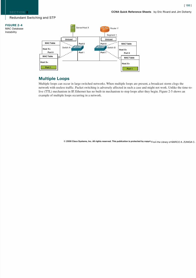
8/12/2019 59811139 CCNA Quick Reference Sheets
http://slidepdf.com/reader/full/59811139-ccna-quick-reference-sheets 186/311
SECTION 2
Redundant Switching and STP
[ 187 ]
CCNA Quick Reference Sheets by Eric Rivard and Jim Doherty
FIGURE 2-5Network ExperiencingMultiple Loops
S er ver/Ho s t
LoopBroad ca s t
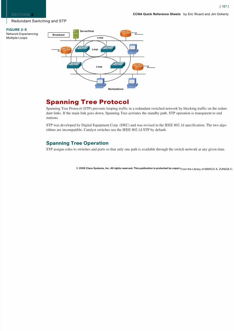
8/12/2019 59811139 CCNA Quick Reference Sheets
http://slidepdf.com/reader/full/59811139-ccna-quick-reference-sheets 187/311
Spanning Tree ProtocolSpanning Tree Protocol (STP) prevents looping traffic in a redundant switched network by blocking traffic on the redun-dant links. If the main link goes down, Spanning Tree activates the standby path. STP operation is transparent to endstations.
STP was developed by Digital Equipment Corp. (DEC) and was revised in the IEEE 802.1d specification. The two algo-rithms are incompatible. Catalyst switches use the IEEE 802.1d STP by default.
Spanning Tree OperationSTP assigns roles to switches and ports so that only one path is available through the switch network at any given time.
© 2008 Cisco Systems, Inc. All rights reserved. This publication is protected by copyright. Please see page 311 for more details.
Loop
Loop
Work s tat ion s
From the Library of MARCO A. ZUNIGA C.

8/12/2019 59811139 CCNA Quick Reference Sheets
http://slidepdf.com/reader/full/59811139-ccna-quick-reference-sheets 188/311
SECTION 2
Redundant Switching and STP
Spanning Tree must select the following:
n One root bridge
[ 189 ]
CCNA Quick Reference Sheets by Eric Rivard and Jim Doherty

8/12/2019 59811139 CCNA Quick Reference Sheets
http://slidepdf.com/reader/full/59811139-ccna-quick-reference-sheets 189/311
n One root port per nonroot bridge
n One designated port per network segment
Selecting the Root BridgeSwitches running STP exchange information at regular intervals using a frame called the bridge protocol data unit(BPDU). Each bridge has a unique bridge ID. The bridge ID contains the bridge MAC address and a priority number. Themidrange value of 32768 is the default priority. The bridge with the lowest bridge ID is selected as the root bridge. Whenswitches have the same priority, the one with the lowest MAC address is the root bridge. Figure 2-7 shows switch X asthe root bridge.
Spanning Tree Election CriteriaSpanning Tree builds paths from the root bridge along the fastest links. It selects paths according to the following criteria:
1. Lowest path cost to the root bridge
2. Lowest sender bridge ID
3. Lowest sender port ID
© 2008 Cisco Systems, Inc. All rights reserved. This publication is protected by copyright. Please see page 311 for more details.
FIGURE 2-7Root Bridge Selection
Swi tch XDefa u lt Pr ior ity 327 68
(8000 hex)MAC 0 c 0011111111
Swi tch YDefa u lt Pr ior ity 327 68(8000 hex)MAC 0 c 0022222222
BPDU
From the Library of MARCO A. ZUNIGA C.
SECTION 2
Redundant Switching and STP
Port StatesFrames take a finite amount of time to travel or propagate through the network. This delay is known as propagation delay.
[ 190 ]
CCNA Quick Reference Sheets by Eric Rivard and Jim Doherty

8/12/2019 59811139 CCNA Quick Reference Sheets
http://slidepdf.com/reader/full/59811139-ccna-quick-reference-sheets 190/311
When a link goes down, Spanning Tree activates previously blocked links. This information is sent throughout thenetwork, but not all switches receive it at the same time. To prevent temporary loops, switches wait until the entire
network is updated before setting any ports to the forwarding state. Each switch port in a network running STP is in oneof the following states listed in Table 2-2.
Table 2-2 Spanning Tree Port StatesPort State Timer Actions
Blocking Max Age (20 sec) Receives BPDUs, discards frames, does not learn MAC addresses
Listening Forward Delay (15 sec) Receives BPDUs to determine its role in STP, discards frames and MAC addresses
Learning Forward Delay Receives and transmits BPDUs, does not learn MAC addresses, discards frames
Forwarding — Forwards frames, learns MAC addresses, receives and transmits BPDUs
The forward delay is the time it takes for a port to go to a higher state. It usually takes 50 seconds for a port to go fromthe blocking state to the forwarding state, but the timers can be adjusted.
Spanning Tree RecalculationWhen a link fails, the network topology must change. Connectivity is reestablished by placing key blocked ports in theforwarding state.
In Figure 2-8, if switch X fails, switch Y does not receive the BPDU. If the BPDU is not received before the MAXAGEtimer expires, Spanning Tree begins recalculating the network. In the figure, switch Y is now the root bridge. If switch Xcomes back up, Spanning Tree recalculates the network, and switch X is once again the root bridge.
© 2008 Cisco Systems, Inc. All rights reserved. This publication is protected by copyright. Please see page 311 for more details.From the Library of MARCO A. ZUNIGA C.

8/12/2019 59811139 CCNA Quick Reference Sheets
http://slidepdf.com/reader/full/59811139-ccna-quick-reference-sheets 191/311

8/12/2019 59811139 CCNA Quick Reference Sheets
http://slidepdf.com/reader/full/59811139-ccna-quick-reference-sheets 192/311

8/12/2019 59811139 CCNA Quick Reference Sheets
http://slidepdf.com/reader/full/59811139-ccna-quick-reference-sheets 193/311

8/12/2019 59811139 CCNA Quick Reference Sheets
http://slidepdf.com/reader/full/59811139-ccna-quick-reference-sheets 194/311

8/12/2019 59811139 CCNA Quick Reference Sheets
http://slidepdf.com/reader/full/59811139-ccna-quick-reference-sheets 195/311

8/12/2019 59811139 CCNA Quick Reference Sheets
http://slidepdf.com/reader/full/59811139-ccna-quick-reference-sheets 196/311

8/12/2019 59811139 CCNA Quick Reference Sheets
http://slidepdf.com/reader/full/59811139-ccna-quick-reference-sheets 197/311
SECTION 2
Redundant Switching and STP
Aging Time 300
Interface Role Sts Cost Prio.Nbr Type
————- —— —- —— ———— ——
Gi0/1 D FWD 4 128 1 P2
[ 198 ]
CCNA Quick Reference Sheets by Eric Rivard and Jim Doherty

8/12/2019 59811139 CCNA Quick Reference Sheets
http://slidepdf.com/reader/full/59811139-ccna-quick-reference-sheets 198/311
Gi0/1 Desg FWD 4 128.1 P2p
Gi0/2 Desg FWD 4 128.2 P2p
EtherChannelEtherChannel is a Cisco feature that allows combining of up to eight physical links into one logical connection. Thislogical connection load-balances traffic between the physical links and is seen by Spanning Tree as one link. Thus withEtherChannel, instead of a redundant link not being used, all physical links are forwarding traffic.
EtherChannel provides an easy way to increase network bandwidth. Fast Ethernet, Gigabit Ethernet, and 10 GigabitEthernet links can be configured for EtherChannel. If one of the physical links in the EtherChannel group fails, the other
links still forward traffic.
Securing the Expanded NetworkAs also mentioned in ICND1, you must ensure that the network is secure from unauthorized activity. Ways to secure thenetwork include
n Physical security
n
Switch security (switch authentication)n Port-based authentication
© 2008 Cisco Systems, Inc. All rights reserved. This publication is protected by copyright. Please see page 311 for more details.From the Library of MARCO A. ZUNIGA C.

8/12/2019 59811139 CCNA Quick Reference Sheets
http://slidepdf.com/reader/full/59811139-ccna-quick-reference-sheets 199/311

8/12/2019 59811139 CCNA Quick Reference Sheets
http://slidepdf.com/reader/full/59811139-ccna-quick-reference-sheets 200/311
SECTION 2
Redundant Switching and STP
To verify port security, use the show port-security command, as follows:
Cat2960# show port-security
Secure Port MaxSecureAddr CurrentAddr SecurityViolation Security Action
[ 201 ]
CCNA Quick Reference Sheets by Eric Rivard and Jim Doherty

8/12/2019 59811139 CCNA Quick Reference Sheets
http://slidepdf.com/reader/full/59811139-ccna-quick-reference-sheets 201/311
(Count) (Count) (Count)
—————————————————————————————————————-Fa0/1 1 0 0 Restrict
—————————————————————————————————————-
Total Addresses in System (excluding one mac per port) : 0
Max Addresses limit in System (excluding one mac per port) : 8320
Securing Unused PortsTo secure unused ports, either disable the port or place the port in an unused VLAN.
A switch port is disabled by issuing the shutdown interface command.
Port-Based AuthenticationPort-based authentication prevents unauthorized devices from gaining access to the network. Based on 802.1x, port-basedauthentication requires a client to be authenticated to a server before it is allowed on the LAN.
802.1x is a standards-based method that defines client-server–based access control and has the following device roles, asdisplayed in Figure 2-10:
n Client: The device (workstation) that requests access to the LAN. Must be running 802.1x-compliant client software.
n Authentication server: Performs the authentication of the client, validating the identity of the client. Currently, aRADIUS server with Extensible Authentication Protocol (EAP) is the only supported authentication server.
n Switch: Controls the physical access to the network based on the authentication status of the client. Acts as a proxybetween the client and authentication server.
© 2008 Cisco Systems, Inc. All rights reserved. This publication is protected by copyright. Please see page 311 for more details.From the Library of MARCO A. ZUNIGA C.
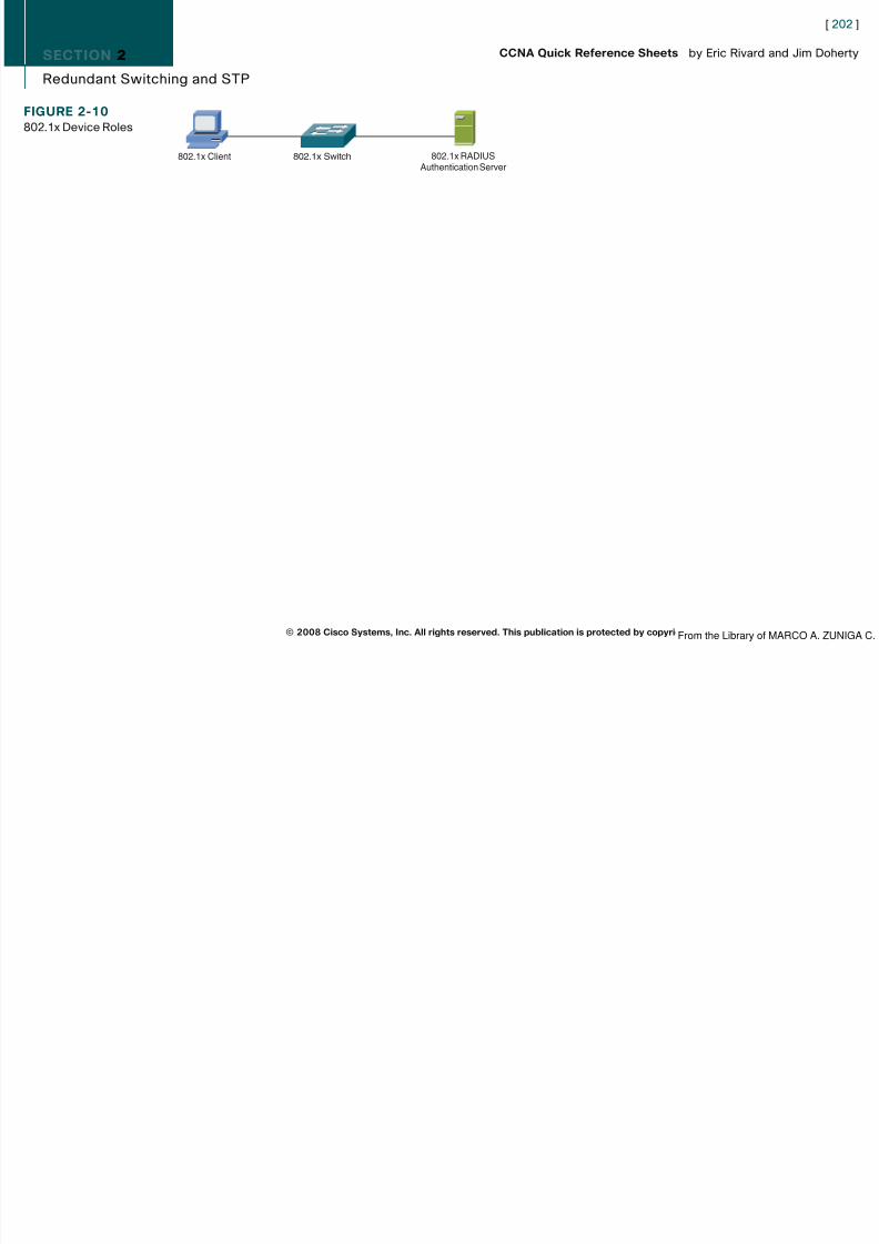
8/12/2019 59811139 CCNA Quick Reference Sheets
http://slidepdf.com/reader/full/59811139-ccna-quick-reference-sheets 202/311
SECTION 3
Troubleshooting Switched Networks
Section 3Troubleshooting Switched Networks
[ 203 ]
CCNA Quick Reference Sheets by Eric Rivard and Jim Doherty
8/12/2019 59811139 CCNA Quick Reference Sheets
http://slidepdf.com/reader/full/59811139-ccna-quick-reference-sheets 203/311
Troubleshooting Switched NetworksIn a switched environment, typical issues include physical issues or hardware problems, Layer 2 issues, and configurationissues. Physical issues can include port failures, network interface card (NIC) failures, and port configuration issues.
Layer 2 issues can include links not properly trunking, CAM table inconsistencies (the CAM table is the table that storesall the MAC addresses and the ports associated with the MAC addresses), or spanning-tree issues.
Configuration issues can include these issues and inconsistencies in configuration such as VTP, VLANs, or Spanning Tree.
General Troubleshooting SuggestionsThe following are three suggestions to general switch troubleshooting:
n Become familiar with normal switch operation.
n Have an accurate physical and logical map of the network.
n Do not assume a component is working without checking it first.
Troubleshooting Port Connectivity ProblemsCommon causes for port connectivity problems include hardware issues, configuration issues, and traffic issues.
© 2008 Cisco Systems, Inc. All rights reserved. This publication is protected by copyright. Please see page 311 for more details.From the Library of MARCO A. ZUNIGA C.

8/12/2019 59811139 CCNA Quick Reference Sheets
http://slidepdf.com/reader/full/59811139-ccna-quick-reference-sheets 204/311

8/12/2019 59811139 CCNA Quick Reference Sheets
http://slidepdf.com/reader/full/59811139-ccna-quick-reference-sheets 205/311

8/12/2019 59811139 CCNA Quick Reference Sheets
http://slidepdf.com/reader/full/59811139-ccna-quick-reference-sheets 206/311
SECTION 3
Troubleshooting Switched Networks
VLAN problems are classified into two categories: intraVLAN and interVLAN connectivity. Problems within each cate-gory are as follows:
n Slow collision domain connectivity
[ 207 ]
CCNA Quick Reference Sheets by Eric Rivard and Jim Doherty

8/12/2019 59811139 CCNA Quick Reference Sheets
http://slidepdf.com/reader/full/59811139-ccna-quick-reference-sheets 207/311
n Slow broadcast domain connectivity (slow VLAN)
n Slow broadcast domain interVLAN connectivity
Troubleshooting Collision Domain IssuesCauses for collision domain issues include the following:
n The segment is overloaded or oversubscribed.
n Bad cabling on the segment.
n NICs on the segment do not have compatible settings.
n Faulty NICs.
Troubleshooting Slow IntraVLANsCause for slowness between hosts on the same VLAN can be caused by
n Traffic loops
n Overloaded or oversubscribed VLANn Switch congestion
n Misconfiguration
n Hardware problems
© 2008 Cisco Systems, Inc. All rights reserved. This publication is protected by copyright. Please see page 311 for more details.From the Library of MARCO A. ZUNIGA C.
SECTION 3
Troubleshooting Switched Networks
Troubleshooting InterVLAN ConnectivityMost interVLAN connectivity issues are caused by misconfiguration. InterVLAN routing was probably not properlyconfigured and needs to be configured to route between the VLANs.
[ 208 ]
CCNA Quick Reference Sheets by Eric Rivard and Jim Doherty

8/12/2019 59811139 CCNA Quick Reference Sheets
http://slidepdf.com/reader/full/59811139-ccna-quick-reference-sheets 208/311
Troubleshooting TrunkingMost trunking problems occur because of misconfiguration on the trunking links. However, first verify that the interfacesare physically working. Here are some common trunking issues:
n Both sides of the links are not set to the correct trunking mode. For example, both sides of the link are set to auto.
n The same trunking encapsulation is not used on both sides.
n A native VLAN mismatch exists.
Troubleshooting VTPVTP problems occur when a misconfiguration exists between the switches and VTP information is not propagating. Acommon indication that a switch is experiencing a VTP problem is when the switch is not receiving or updating itsVLAN information.
The following are common things to check when troubleshooting VTP problems:
n Make sure that trunking is configured between the switches. VTP information is sent over trunk links.
n Make sure that the domain name matches on both switches. The domain name is case sensitive.
n If using a VTP password, make sure that the password is the same on both switches. The password is case sensitive.
n Verify that the switch is in the proper mode: server, client, or transparent.
© 2008 Cisco Systems, Inc. All rights reserved. This publication is protected by copyright. Please see page 311 for more details.From the Library of MARCO A. ZUNIGA C.

8/12/2019 59811139 CCNA Quick Reference Sheets
http://slidepdf.com/reader/full/59811139-ccna-quick-reference-sheets 209/311
SECTION 4
Routing Operations and VLSM
Part II: Routing
S ti 4
[ 210 ]
CCNA Quick Reference Sheets by Eric Rivard and Jim Doherty

8/12/2019 59811139 CCNA Quick Reference Sheets
http://slidepdf.com/reader/full/59811139-ccna-quick-reference-sheets 210/311
Section 4Routing Operations and VLSM
Routing OverviewRouting is the process of getting packets and messages from one location to another.
A router needs the following key information, as displayed in Figure 4-1:
n Destination address: The destination (typically an IP address) of the information being sent. This includes thesubnet address.
n Possible routes: Likely routes to get from source to destination.
n Best route: The best path to the intended destination.
n Status of routes: Known paths to destinations.
A router is constantly learning about routes in the network and storing this information in its routing table. The routeruses its table to make forwarding decisions. The router learns about routes in one of two ways:
n
Manually (routing information entered by the network administrator)n Dynamically (a routing process running in the network)
© 2008 Cisco Systems, Inc. All rights reserved. This publication is protected by copyright. Please see page 311 for more details.From the Library of MARCO A. ZUNIGA C.
SECTION 4
Routing Operations and VLSM
[ 211 ]
CCNA Quick Reference Sheets by Eric Rivard and Jim Doherty
FIGURE 4-1Information Neededby Router for Routing 10.120.2.0 172.16.1.0

8/12/2019 59811139 CCNA Quick Reference Sheets
http://slidepdf.com/reader/full/59811139-ccna-quick-reference-sheets 211/311
Dynamic Routing OverviewRouting protocols determine paths between routers and maintain routing tables. Dynamic routing uses routing protocolsto disseminate knowledge throughout the network. A routing protocol defines communication rules and interprets network layer address information. Routing protocols describe the following:
n Routing update methods
n Information contained in updates
n When updates are sent
n Paths to other routers
© 2008 Cisco Systems, Inc. All rights reserved. This publication is protected by copyright. Please see page 311 for more details.
Routed Protocol: IP
E0
S0
Network Protocol
DestinationNetwork
ExitInterface
Connected
Learned
10.120.2.0
172.16.1.0
E0
S0
From the Library of MARCO A. ZUNIGA C.

8/12/2019 59811139 CCNA Quick Reference Sheets
http://slidepdf.com/reader/full/59811139-ccna-quick-reference-sheets 212/311
SECTION 4
Routing Operations and VLSM
[ 213 ]
CCNA Quick Reference Sheets by Eric Rivard and Jim Doherty
FIGURE 4-3AdministrativeDistance DeterminesPath
I need to senda packet toNetwork E.Both Router Band C will get
EIGRPAdministrativeDistance=100

8/12/2019 59811139 CCNA Quick Reference Sheets
http://slidepdf.com/reader/full/59811139-ccna-quick-reference-sheets 213/311
Table 4-1 shows the default administrative distance values.
Table 4-1 Default Administrative Distance ValuesRoute Source Default Distance
Connected interface 0
Static route 1
EIGRP 90
IGRP 100
OSPF 110
RIP 120
External EIGRP 170
Unknown 255
© 2008 Cisco Systems, Inc. All rights reserved. This publication is protected by copyright. Please see page 311 for more details.
it there.Which routeis best?
Distance 100
RIPAdministrativeDistance=120 E
C
A B
D
From the Library of MARCO A. ZUNIGA C.
8/12/2019 59811139 CCNA Quick Reference Sheets
http://slidepdf.com/reader/full/59811139-ccna-quick-reference-sheets 214/311
SECTION 4
Routing Operations and VLSM
[ 215 ]
CCNA Quick Reference Sheets by Eric Rivard and Jim Doherty
FIGURE 4-4Router on a Stick
802.1 QRouter On a Stick

8/12/2019 59811139 CCNA Quick Reference Sheets
http://slidepdf.com/reader/full/59811139-ccna-quick-reference-sheets 215/311
Dividing Physical Interfaces into SubinterfacesInterVLAN routing using router on a stick requires the use of subinterfaces. A subinterface is a logical, addressable inter-face on the router’s physical port. A single port can have many subinterfaces. Router on a stick requires a Fast Ethernet(or Gigabit Ethernet) port, with one subinterface configured per VLAN.
In Figure 4-5, the FastEthernet 0/0 interface is divided into multiple subinterfaces (FastEthernet 0.1, FastEthernet 0.2, andso on).
© 2008 Cisco Systems, Inc. All rights reserved. This publication is protected by copyright. Please see page 311 for more details.
VLAN 1 VLAN 2
10.2.2.210.1.1.2
FIGURE 4-5Using Subinterfaces FastEthernet 0/0.1
FastEthernet 0/0.2FastEthernet 0/0.3
FastEthernet 0/0
From the Library of MARCO A. ZUNIGA C.

8/12/2019 59811139 CCNA Quick Reference Sheets
http://slidepdf.com/reader/full/59811139-ccna-quick-reference-sheets 216/311
SECTION 4
Routing Operations and VLSM
[ 217 ]
CCNA Quick Reference Sheets by Eric Rivard and Jim Doherty
FIGURE 4-6Distance Vector RouteInformation
AC
B

8/12/2019 59811139 CCNA Quick Reference Sheets
http://slidepdf.com/reader/full/59811139-ccna-quick-reference-sheets 217/311
Distance accumulation keeps track of the routing distance between any two points in the network, but the routers do notknow the exact topology of an internetwork.
How Information Is Discovered with Distance VectorsNetwork discovery is the process of learning about nondirectly connected destinations. As the network discoveryproceeds, routers accumulate metrics and learn the best paths to various destinations. In Figure 4-7, each directlyconnected network has a distance of 0. Router A learns about other networks based on information it receives fromRouter B. Router A increments the distance metric for any route learned by Router B. For example, Router B knows
about the networks to Router C, which is directly connected. Router B increments its distance metrics by 1 and sendsthem to Router A.
© 2008 Cisco Systems, Inc. All rights reserved. This publication is protected by copyright. Please see page 311 for more details.
Vector—In Which Direction?
Distance—How Far?
RoutingTable
RoutingTable
RoutingTable
RoutingTable
D
D AC B
From the Library of MARCO A. ZUNIGA C.

8/12/2019 59811139 CCNA Quick Reference Sheets
http://slidepdf.com/reader/full/59811139-ccna-quick-reference-sheets 218/311

8/12/2019 59811139 CCNA Quick Reference Sheets
http://slidepdf.com/reader/full/59811139-ccna-quick-reference-sheets 219/311

8/12/2019 59811139 CCNA Quick Reference Sheets
http://slidepdf.com/reader/full/59811139-ccna-quick-reference-sheets 220/311
SECTION 4
Routing Operations and VLSM
[ 221 ]
CCNA Quick Reference Sheets by Eric Rivard and Jim Doherty
FIGURE 4-10Counting to Infinity
C
10.1.0.0 10.2.0.0 10.3.0.0 10.4.0.0
E0 S0 S0 S1 S0 E0
X
A CB
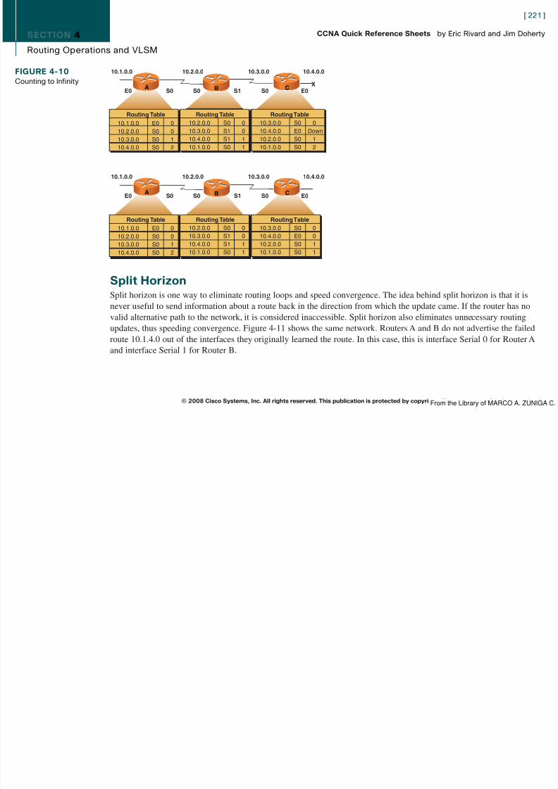
8/12/2019 59811139 CCNA Quick Reference Sheets
http://slidepdf.com/reader/full/59811139-ccna-quick-reference-sheets 221/311
Split HorizonSplit horizon is one way to eliminate routing loops and speed convergence. The idea behind split horizon is that it isnever useful to send information about a route back in the direction from which the update came. If the router has no
valid alternative path to the network, it is considered inaccessible. Split horizon also eliminates unnecessary routingupdates, thus speeding convergence. Figure 4-11 shows the same network. Routers A and B do not advertise the failedroute 10.1.4.0 out of the interfaces they originally learned the route. In this case, this is interface Serial 0 for Router Aand interface Serial 1 for Router B.
© 2008 Cisco Systems, Inc. All rights reserved. This publication is protected by copyright. Please see page 311 for more details.
10.1.0.0 E0 010.2.0.0 S0 010.3.0.0 S0 110.4.0.0 S0 2
Routing Table Routing Table
10.2.0.0 S0 010.3.0.0 S1 010.4.0.0 S1 110.1.0.0 S0 1
Routing Table
10.3.0.0 S0 010.4.0.0 E0 Down10.2.0.0 S0 110.1.0.0 S0 2
C
10.1.0.0 10.2.0.0 10.3.0.0 10.4.0.0
E0 S0 S0 S1 S0 E0
10.1.0.0 E0 010.2.0.0 S0 010.3.0.0 S0 110.4.0.0 S0 2
Routing Table Routing Table10.2.0.0 S0 010.3.0.0 S1 010.4.0.0 S1 110.1.0.0 S0 1
Routing Table10.3.0.0 S0 010.4.0.0 E0 010.2.0.0 S0 110.1.0.0 S0 1
A CB
From the Library of MARCO A. ZUNIGA C.

8/12/2019 59811139 CCNA Quick Reference Sheets
http://slidepdf.com/reader/full/59811139-ccna-quick-reference-sheets 222/311

8/12/2019 59811139 CCNA Quick Reference Sheets
http://slidepdf.com/reader/full/59811139-ccna-quick-reference-sheets 223/311

8/12/2019 59811139 CCNA Quick Reference Sheets
http://slidepdf.com/reader/full/59811139-ccna-quick-reference-sheets 224/311

8/12/2019 59811139 CCNA Quick Reference Sheets
http://slidepdf.com/reader/full/59811139-ccna-quick-reference-sheets 225/311

8/12/2019 59811139 CCNA Quick Reference Sheets
http://slidepdf.com/reader/full/59811139-ccna-quick-reference-sheets 226/311
SECTION 4
Routing Operations and VLSM
Variable-Length Subnet Mask (VLSM)VLSMs were developed to allow multiple levels of subnetting in an IP network. This allows network administrators toovercome the limitations of fixed-sized subnets within a network and, in effect, subnet a subnet. VLSMs are not availablein RIPv1.
[ 227 ]
CCNA Quick Reference Sheets by Eric Rivard and Jim Doherty
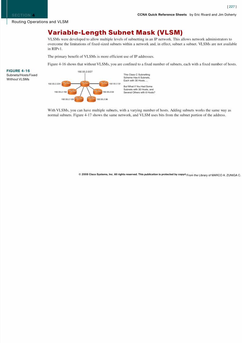
8/12/2019 59811139 CCNA Quick Reference Sheets
http://slidepdf.com/reader/full/59811139-ccna-quick-reference-sheets 227/311
in RIPv1.
The primary benefit of VLSMs is more efficient use of IP addresses.
Figure 4-16 shows that without VLSMs, you are confined to a fixed number of subnets, each with a fixed number of hosts.
With VLSMs, you can have multiple subnets, with a varying number of hosts. Adding subnets works the same way asnormal subnets. Figure 4-17 shows the same network, and VLSM uses bits from the subnet portion of the address.
© 2008 Cisco Systems, Inc. All rights reserved. This publication is protected by copyright. Please see page 311 for more details.
FIGURE 4-16Subnets/Hosts FixedWithout VLSMs
192.55.2.0/27
192.55.2.224
192.55.2.192
192.55.2.128 192.55.2.96
192.55.2.32
192.55.2.64
This Class C SubnettingScheme Has 6 Subnets,Each with 30 Hosts….
But What I f You Had SomeSubnets with 30 Hosts, andSeveral Others with 6 Hosts?
From the Library of MARCO A. ZUNIGA C.
SECTION 4
Routing Operations and VLSM
[ 228 ]
CCNA Quick Reference Sheets by Eric Rivard and Jim Doherty
FIGURE 4-17VLSMs Increase theNumber ofSubnet/HostPossibilities
192.55.2.0/27
192 .55 . 2. 011
192 .55 . 2. 01
Network Subnet Host
00000

8/12/2019 59811139 CCNA Quick Reference Sheets
http://slidepdf.com/reader/full/59811139-ccna-quick-reference-sheets 228/311
Summarizing RoutesIn large networks, it is impractical for a router to maintain tables with hundreds of thousands of routes. Route summariza-tion (also called route aggregation or supernetting) reduces the number of routes that a router must maintain by represent-ing a series of network numbers in a single summary address.
Router summarization is most effective within a subnetted environment when the network addresses are in contiguousblocks in powers of 2.
© 2008 Cisco Systems, Inc. All rights reserved. This publication is protected by copyright. Please see page 311 for more details.
192 .55 . 2. 011192 .55 . 2. 01
Network Host
Subnet VLSM
192.55.2.224
192.55.2.192
192.55.2.128 192.55.2.29
192.55.2.32
192.55.2.64
The New SubnetsCreated Using VLSMNow Each Have 6 Hosts
192.55.2.112 192.55.2.104
From the Library of MARCO A. ZUNIGA C.

8/12/2019 59811139 CCNA Quick Reference Sheets
http://slidepdf.com/reader/full/59811139-ccna-quick-reference-sheets 229/311
SECTION 5
Implementing OSPF in a Single Area
Section 5Implementing OSPF in a Single AreaOSPF is an interior gateway protocol based on link state rather than distance vectors. OSPF uses Dijkstra’s shortest path
[ 230 ]
CCNA Quick Reference Sheets by Eric Rivard and Jim Doherty

8/12/2019 59811139 CCNA Quick Reference Sheets
http://slidepdf.com/reader/full/59811139-ccna-quick-reference-sheets 230/311
g y p j p
first (SPF) algorithm to determine the best path to each network. OSPF was developed in the 1980s as an answer to RIP’sinability to scale well in large IP networks.
OSPF is an open-standard, classless protocol that converges quickly and uses costs as a metric. Cisco IOS automaticallycalculates cost based on the interface bandwidth.
When a router is configured for OSPF, the first thing the router does is create a topology table of the network. OSPF doesthis by sending Hellos out each OSPF interface, while listening for Hellos from other routers. If the routers share acommon data link and agree on certain parameters set in their Hello packets, they become neighbors. If these parametersare different, they do not become neighbors and communication stops. OSPF routers can form adjacencies with certainneighbor routers. The routers that OSPF routers build adjacencies with are determined by the data link media type.
After adjacencies have been formed, each router sends link-state advertisements (LSA) to all adjacent routers. TheseLSAs describe the state of each of the router’s links. Because of the varying types of link-state information, OSPF definesmultiple LSA types.
Finally, routers receiving an LSA from neighbors record the LSA in a link-state database and flood a copy of the LSA toall other neighbors. When all databases are complete, each router uses the SPF algorithm to calculate a loop-free, best-path topology and builds its routing table based on this topology.
© 2008 Cisco Systems, Inc. All rights reserved. This publication is protected by copyright. Please see page 311 for more details.From the Library of MARCO A. ZUNIGA C.

8/12/2019 59811139 CCNA Quick Reference Sheets
http://slidepdf.com/reader/full/59811139-ccna-quick-reference-sheets 231/311
SECTION 5
Implementing OSPF in a Single Area
Each Hello packets contains the following:
n Router ID of the originating router
n Area ID of the originating router interface
Add k f h i i i i f
[ 232 ]
CCNA Quick Reference Sheets by Eric Rivard and Jim Doherty

8/12/2019 59811139 CCNA Quick Reference Sheets
http://slidepdf.com/reader/full/59811139-ccna-quick-reference-sheets 232/311
n Address mask of the originating router interface
n Authentication type and information of the originating router interface
n HelloInterval
n RouterDeadInterval
n Router priority
n DR and BDR
n 5 flag bits for optional capabilities
n Router IDs of the originating router’s neighbors
Hello packets are periodically sent out each interface using IP multicast address 224.0.0.5 (AllSPFRouters). TheHelloInterval each router uses to send out the Hello protocol is based on the media type. The default HelloInterval of broadcast, point-to-point, and point-to-multipoint networks is 10 seconds. On NBMA networks the default HelloIntervalis 30 seconds.
For OSPF-enabled routers to become neighbors, certain parameters in the Hello packet must match. These parameters areas follows:
n Subnet mask used on the subnet
n Subnet number
© 2008 Cisco Systems, Inc. All rights reserved. This publication is protected by copyright. Please see page 311 for more details.From the Library of MARCO A. ZUNIGA C.

8/12/2019 59811139 CCNA Quick Reference Sheets
http://slidepdf.com/reader/full/59811139-ccna-quick-reference-sheets 233/311

8/12/2019 59811139 CCNA Quick Reference Sheets
http://slidepdf.com/reader/full/59811139-ccna-quick-reference-sheets 234/311

8/12/2019 59811139 CCNA Quick Reference Sheets
http://slidepdf.com/reader/full/59811139-ccna-quick-reference-sheets 235/311
SECTION 5
Implementing OSPF in a Single Area
Transmit Delay is 1 sec, State BDR, Priority 1
Designated Router (ID) 172.16.0.1, Interface address 10.1.1.2
Backup Designated router (ID) 172.16.0.2, Interface address 10.1.1.1
Timer intervals configured, Hello 10, Dead 40, Wait 40, Retransmit 5
Hello due in 00:00:06
[ 236 ]
CCNA Quick Reference Sheets by Eric Rivard and Jim Doherty

8/12/2019 59811139 CCNA Quick Reference Sheets
http://slidepdf.com/reader/full/59811139-ccna-quick-reference-sheets 236/311
Index 1/1, flood queue length 0Next 0x0(0)/0x0(0)
Last flood scan length is 2, maximum is 2
Last flood scan time is 0 msec, maximum is 4 msec
Neighbor Count is 1, Adjacent neighbor count is 1
Adjacent with neighbor 172.16.0.1 (Designated Router)
Suppress hello for 0 neighbor(s)
To analyze the OSPF events, use the debug ip ospf events command.
Load Balancing with OSPFLoad balancing is a function of Cisco IOS router software and is supported for static routes, RIP, RIPv2, IGRP, EIGRP,OSPF, IS-IS, and BGP.
When a router has multiple paths with the same AD and cost to a destination, packets are load-balanced across the paths.OSPF only supports equal-cost load balancing. EIGRP also supports unequal-cost load balancing.
Per-Destination and Per-Packet Load BalancingIn per-destination load balancing, the router distributes packets based on the destination address.
In per-packet load balancing, the router sends one packet for one destination over the first path, and the second packet forthe same destination over the second path.
© 2008 Cisco Systems, Inc. All rights reserved. This publication is protected by copyright. Please see page 311 for more details.From the Library of MARCO A. ZUNIGA C.
SECTION 5
Implementing OSPF in a Single Area
Load Balancing with Different CostsOSPF does not support unequal-cost load balancing. If OSPF has two unequal links to a destination, only the lowest-costpath is used. The other path remains idle. To use the other link for load balancing, you need to manually change the costof the interface.
[ 237 ]
CCNA Quick Reference Sheets by Eric Rivard and Jim Doherty
8/12/2019 59811139 CCNA Quick Reference Sheets
http://slidepdf.com/reader/full/59811139-ccna-quick-reference-sheets 237/311
Because OSPF’s metric is based on cost, to load-balance between two links with different costs, you have to manuallyconfigure each interface with the same cost. The ip ospf cost interface-cost interface command sets the OSPF cost of aninterface. In the example that follows, you would enter the following commands to make both interfaces have the samecost:
RouterA(config)# interface serial 0/0RouterA(config-if)# ip ospf cost 10
RouterA(config-if)# interface serial 0/1
RouterA(config-if)# ip ospf cost 10
Authentication with OSPFOSPF authentication prevents unauthorized routers from forming adjacencies with OSPF-enabled routers.
OSPF supports three types of authentication:
n Null authentication
n Plain-text authentication
nMD5 authentication
© 2008 Cisco Systems, Inc. All rights reserved. This publication is protected by copyright. Please see page 311 for more details.From the Library of MARCO A. ZUNIGA C.
SECTION 5
Implementing OSPF in a Single Area
Configuring Plain-Text AuthenticationThe following steps configure OSPF plain-text authentication:
Step 1. Assign a password to be used with the ip ospf authentication-key password interface command.
Step 2 Specify the authentication type with the ip ospf authentication interface command
[ 238 ]
CCNA Quick Reference Sheets by Eric Rivard and Jim Doherty

8/12/2019 59811139 CCNA Quick Reference Sheets
http://slidepdf.com/reader/full/59811139-ccna-quick-reference-sheets 238/311
Step 2. Specify the authentication type with the ip ospf authentication interface command.
Step 3. Configure authentication under the OSPF area using the area area-id authentication command.
The following enables plain-text authentication using the password of cisco on interface serial 0/0:
RouterA(config)# interface serial 0/0RouterA(config-if)# ip ospf authentication-key ciscoRouterA(config-if)# ip ospf authentication
RouterA(config-if)# !
RouterA(config)# router ospf 1
RouterA(config-if)# area 0 authentication
Verifying Plain-Text AuthenticationThe show ip ospf interface command shows whether OSPF authentication is enabled. The highlighted item in thefollowing example shows that plain-text authentication is enabled:
RouterA# show ip ospf interface serial0
Serial0 is up, line protocol is up
Internet Address 192.16.0.1/24, Area 0
Process ID 10, Router ID 172.16.0.1, Network Type POINT_TO_POINT, Cost: 64Transmit Delay is 1 sec, State POINT_TO_POINT,
Timer intervals configured, Hello 10, Dead 40, Wait 40, Retransmit 5Hello due in 00:00:04
Index 2/2, flood queue length 0
Next 0x0(0)/0x0(0)
© 2008 Cisco Systems, Inc. All rights reserved. This publication is protected by copyright. Please see page 311 for more details.From the Library of MARCO A. ZUNIGA C.
SECTION 5
Implementing OSPF in a Single Area
Last flood scan length is 1, maximum is 1
Last flood scan time is 0 msec, maximum is 4 msec
Neighbor Count is 0, Adjacent neighbor count is 0
Suppress hello for 0 neighbor(s)
Simple password authentication enabled
[ 239 ]
CCNA Quick Reference Sheets by Eric Rivard and Jim Doherty

8/12/2019 59811139 CCNA Quick Reference Sheets
http://slidepdf.com/reader/full/59811139-ccna-quick-reference-sheets 239/311
Configuring MD5 AuthenticationConfiguring MD5 authentication between two OSPF routers is similar to configuring plain-text authentication, except youneed to have a key ID and a password.
The ip ospf message-digest-key key-id md5 password interface command sets the password between the two routers.The area area-id authentication message-digest command enables MD5 for the OSPF area. The following commandsenable MD5 authentication for key 1 with the password of cisco:
RouterA(config)# interface serial 0/0
RouterA(config-if)# ip ospf message-digest-key 1 md5 cisco
RouterA(config-if)# ip ospf authentication message-digest
RouterA(config-if)#
RouterA(config)# router ospf 1
RouterA(config-router)# area 0 authentication message-digest
Verifying MD5 AuthenticationThe show ip ospf interface command shows whether OSPF authentication is enabled. The highlighted item in thefollowing example shows that MD5 authentication is enabled:
RouterA# show ip ospf interface serial0
Serial0 is up, line protocol is up
Internet Address 192.16.0.1/24, Area 0
Process ID 10, Router ID 172.16.0.1, Network Type POINT_TO_POINT, Cost: 64
© 2008 Cisco Systems, Inc. All rights reserved. This publication is protected by copyright. Please see page 311 for more details.
NOTEThe key-id and password parameters must be thesame between neighbor-ing devices.
From the Library of MARCO A. ZUNIGA C.

8/12/2019 59811139 CCNA Quick Reference Sheets
http://slidepdf.com/reader/full/59811139-ccna-quick-reference-sheets 240/311
SECTION 5
Implementing OSPF in a Single Area
[ 241 ]
CCNA Quick Reference Sheets by Eric Rivard and Jim Doherty
FIGURE 5-1OSPFTroubleshootingFlow Chart
Main

8/12/2019 59811139 CCNA Quick Reference Sheets
http://slidepdf.com/reader/full/59811139-ccna-quick-reference-sheets 241/311
© 2008 Cisco Systems, Inc. All rights reserved. This publication is protected by copyright. Please see page 311 for more details.
See Figure 5-3.OSPF Route Check
See Figure 5-2.
OSPF NeighborStates
What is the OSPFproblem?
Receiving “ospf-4 badlas type error”message
Receiving “can’t allocate router-id”message when configuring OSPF
Receiving “ospf unknown protocol”message when configuring OSPF
The OSPF packet is being corruptedlayer-2 software.
For the OSPF process to begin, therouter must have an interface with avalid IP address in the UP/UP state.
IOS feature set does not support OSPFor you are configuring OSPF on a 1600
or 1800 series router.
OSPF routers not establishing FULLneighbors
OSPF routes missing from routingtable
From the Library of MARCO A. ZUNIGA C.

8/12/2019 59811139 CCNA Quick Reference Sheets
http://slidepdf.com/reader/full/59811139-ccna-quick-reference-sheets 242/311

8/12/2019 59811139 CCNA Quick Reference Sheets
http://slidepdf.com/reader/full/59811139-ccna-quick-reference-sheets 243/311
SECTION 5
Implementing OSPF in a Single Area
Troubleshooting Commandsn show ip ospf interface: Lists the area in which the interface belongs, and neighbors adjacent on the interface.
n show ip ospf neighbor: Lists neighbors and current neighbor status.
n debug ip ospf events: Shows messages for each OSPF packet.
[ 244 ]
CCNA Quick Reference Sheets by Eric Rivard and Jim Doherty

8/12/2019 59811139 CCNA Quick Reference Sheets
http://slidepdf.com/reader/full/59811139-ccna-quick-reference-sheets 244/311
n debug ip ospf packet: Shows log messages that describe the contents of all OSPF packets.
n debug ip ospf hello: Shows messages describing Hello packets and Hello failures.
n debug ip ospf adj: Shows the authentication process if OSPF authentication is configured.
The debug ip ospf adj command is an important command for troubleshooting OSPF adjacencies. OSPF routersexchange Hello packets to create neighbor adjacencies. For an OSPF adjacency to occur, the following four items in anOSPF Hello packet must match:
n
Area IDn Hello/dead intervals
n Authentication password
n Stub area flag
To determine whether any of these Hello packet options do not match, use the debug ip ospf adj command. The followingoutput shows a successful adjacency on the serial 0 interface:
RouterA# debug ip ospf adj
00:50:57: %LINK-3-UPDOWN: Interface Serial0, changed state to down00:50:57: OSPF: Interface Serial0 going Down00:50:57: OSPF: 172.16.10.36 address 192.16.64.1 on Serial0 is dead,
state DOWN
© 2008 Cisco Systems, Inc. All rights reserved. This publication is protected by copyright. Please see page 311 for more details.From the Library of MARCO A. ZUNIGA C.
SECTION 5
Implementing OSPF in a Single Area
00:50:57: OSPF: 70.70.70.70 address 192.16.64.2 on Serial0 is dead,
state DOWN
00:50:57: %OSPF-5-ADJCHG: Process 10, Nbr 70.70.70.70 on Serial0 from
FULL to DOWN, Neighbor Down: Interface down or detached
00:50:58: OSPF: Build router LSA for area 0, router ID 172.16.10.36,seq 0x80000009
[ 245 ]
CCNA Quick Reference Sheets by Eric Rivard and Jim Doherty

8/12/2019 59811139 CCNA Quick Reference Sheets
http://slidepdf.com/reader/full/59811139-ccna-quick-reference-sheets 245/311
seq 0x80000009
00:50:58: %LINEPROTO-5-UPDOWN: Line protocol on Interface Serial0,
changed state to down
00:51:03: %LINK-3-UPDOWN: Interface Serial0, changed state to up
00:51:03: OSPF: Interface Serial0 going Up
00:51:04: OSPF: Build router LSA for area 0, router ID 172.16.10.36,
seq 0x8000000A
00:51:04: %LINEPROTO-5-UPDOWN: Line protocol on Interface Serial0,changed state to up
00:51:13: OSPF: 2 Way Communication to 70.70.70.70 on Serial0,
state 2WAY00:51:13: OSPF: Send DBD to 70.70.70.70 on Serial0 seq 0x2486 opt 0x42
flag 0x7 len 32
00:51:13: OSPF: Rcv DBD from 70.70.70.70 on Serial0 seq 0x19A4 opt 0x42
flag 0x7 len 32 mtu 1500 state EXSTART
00:51:13: OSPF: First DBD and we are not SLAVE00:51:13: OSPF: Rcv DBD from 70.70.70.70 on Serial0 seq 0x2486 opt 0x42
flag 0x2 len 72 mtu 1500 state EXSTART
00:51:13: OSPF: NBR Negotiation Done. We are the MASTER
00:51:13: OSPF: Send DBD to 70.70.70.70 on Serial0 seq 0x2487 opt 0x42flag 0x3 len 72
00:51:13: OSPF: Database request to 70.70.70.70
00:51:13: OSPF: sent LS REQ packet to 192.16.64.2, length 12
© 2008 Cisco Systems, Inc. All rights reserved. This publication is protected by copyright. Please see page 311 for more details.From the Library of MARCO A. ZUNIGA C.

8/12/2019 59811139 CCNA Quick Reference Sheets
http://slidepdf.com/reader/full/59811139-ccna-quick-reference-sheets 246/311
SECTION 6
Implementing EIGRP
Section 6Implementing EIGRPEnhanced IGRP (EIGRP) is a Cisco-proprietary routing protocol. EIGRP is a classless routing protocol, meaning that it
[ 247 ]
CCNA Quick Reference Sheets by Eric Rivard and Jim Doherty

8/12/2019 59811139 CCNA Quick Reference Sheets
http://slidepdf.com/reader/full/59811139-ccna-quick-reference-sheets 247/311
sends the subnet mask of its interfaces in routing updates, which use a complex metric based on bandwidth and delay.EIRGP is an advanced distance vector protocol with some link-state features. As such, EIGRP is classified as a balancedhybrid protocol.
EIGRP Featuresn Protocol-independent modules: EIGRP supports IP, IPv6, Internetwork Packet Exchange (IPX), and AppleTalk.
n Reliable Transport Protocol: RTP controls sending, tracking, and acknowledging updates and EIGRP messages.
n Neighbor discovery/recovery: EIGRP discovers neighboring devices using periodic Hello messages.
n Diffusing Update Algorithm (DUAL): EIGRP uses DUAL to calculate and maintain loop-free paths and provide fastconvergence.
n Partial updates: EIGRP sends partial triggered updates instead of periodic updates.
EIGRP Terminologyn Neighbor table: Lists all adjacent routers. Includes the neighbor’s address and the interface through which it can be
reached. EIGRP routers keep a neighbor table for each routed Layer 3 protocol (IP, IPX, AppleTalk).
n Topology table: Contains all learned routes to a destination. The topology table holds all successor and feasiblesuccessor routes in its table.
n Routing table: Holds the best routes (the successor routes) to each destination.
© 2008 Cisco Systems, Inc. All rights reserved. This publication is protected by copyright. Please see page 311 for more details.From the Library of MARCO A. ZUNIGA C.

8/12/2019 59811139 CCNA Quick Reference Sheets
http://slidepdf.com/reader/full/59811139-ccna-quick-reference-sheets 248/311
SECTION 6
Implementing EIGRP
Load Balancing with EIGRPLoad balancing is a router’s ability to balance traffic over all its network’s ports that are the same metric from the destina-tion address.
EIGRP uses a complex metric based on bandwidth, delay, load, reliability, and MTU to select the best path to a destina-
[ 249 ]
CCNA Quick Reference Sheets by Eric Rivard and Jim Doherty

8/12/2019 59811139 CCNA Quick Reference Sheets
http://slidepdf.com/reader/full/59811139-ccna-quick-reference-sheets 249/311
tion. By default, EIGRP only uses bandwidth and delay to calculate its metric.
By default, EIGRP can automatically load-balance up to 4 equal-cost routes (16 routes being the maximum); this is calledequal-cost load balancing.
Unequal-cost load balancing is when a router can load-balance traffic to a destination through links of different cost orspeeds. In Figure 6-1, Router A has two unequal paths to network 10.1.2.x.
Because the path through Router B has a lower cost than the path through Router C, Router A will route all traffic tonetwork 10.1.2.x through Router B.
To configure Router A to perform unequal-cost load balancing, you need to use the variance multiplier command onRouter A. The multiplier is a variance value between 1 and 128, with the default set to 1.
© 2008 Cisco Systems, Inc. All rights reserved. This publication is protected by copyright. Please see page 311 for more details.
FIGURE 6-1EIGRP Unequal-Cost
Load BalancingRouter A
10 10
20 20
Router B
Router C
10.1.2x
From the Library of MARCO A. ZUNIGA C.

8/12/2019 59811139 CCNA Quick Reference Sheets
http://slidepdf.com/reader/full/59811139-ccna-quick-reference-sheets 250/311
SECTION 6
Implementing EIGRP
Troubleshooting EIGRPFigure 6-2 shows a basic flow chart with the steps to take to approach EIGRP troubleshooting.
[ 251 ]
CCNA Quick Reference Sheets by Eric Rivard and Jim Doherty
FIGURE 6-2EIGRPTroubleshooting
EIGRP Main

8/12/2019 59811139 CCNA Quick Reference Sheets
http://slidepdf.com/reader/full/59811139-ccna-quick-reference-sheets 251/311
© 2008 Cisco Systems, Inc. All rights reserved. This publication is protected by copyright. Please see page 311 for more details.
Flow Chart
See Figure 6-3 EIGRPNeighbor Check
See Figure 6-5 EIGRPRoute Check
EIGRP router is receivinga hello packet that is
sourced from an IP addresson a subnet that is not
configured on the EIGRPreceiving interface.
Verify the variancecommand is configured
correctly
Queries are notreturning to the routerwhen running DUAL
Which best describes theproblem?
Local EIGRP route notestablishing EIGRP neighbors
with neighboring router
Routes missing from routingtable
Receiving “Not on CommonSubnet” error
Load balancing not working
Seeing routes Stuck inActive (SIA)
From the Library of MARCO A. ZUNIGA C.
SECTION 6
Implementing EIGRP
EIGRP Neighbor TroubleshootingWhen EIGRP is not forming neighbor relationships with other EIGRP routers, use the flow charts from Cisco.com inFigures 6-3 and 6-4 to troubleshoot the issue.
[ 252 ]
CCNA Quick Reference Sheets by Eric Rivard and Jim Doherty
FIGURE 6-3EIGRP Neighbor
EIGRP Neighbor Check

8/12/2019 59811139 CCNA Quick Reference Sheets
http://slidepdf.com/reader/full/59811139-ccna-quick-reference-sheets 252/311
© 2008 Cisco Systems, Inc. All rights reserved. This publication is protected by copyright. Please see page 311 for more details.
Check: Part I
Y
Areneighboring routers
attached via the sameprimary network?
(continue with next chart)
Can yousuccessfully ping
between neighbors withpacket sizes up to the
interface MTUsize?
Are the neighborsattached via Frame
Relay Netwokr?
Arebroadcast
packets dropped
from the frame relaybroadcastqueue? 2
Y
Is theframe-relay map
command being usedfor manualmappings?
Y
N
Y
Y
N
N
N
N
N
Ensure tha the frame-relay mapcommand has been configured withthe broadcast keyword. This allows
EIGRP multicast packet deliveryacross the Frame Relay Network.
Check the MTU selling for theneighboring interfaces. Makethem the same, if they are notalready. If they are the same,
there is a Layer 2 problemthat must be fixed. Check
cabling, interfaces, and so on.
EIGRP will not form neighbors over secondary networks:therefore, the neighboring routers should be on the same
primary network.
The primary addressassigned to the interface
must be part of thenetwork used by the
network configurationcommand under EIGRP.
Y
Your frame-relaybroadcast queue may
need to be tuned.Refer to OSPF and
EIGRP Neighbor Loss,RIP and IGRP Update
Loss after Upgrading toCisco IOS 11.2 or later.
Is EIGRPenabled for
appropriate networkson both the local andneighboring router? 1
From the Library of MARCO A. ZUNIGA C.
SECTION 6
Implementing EIGRP
[ 253 ]
CCNA Quick Reference Sheets by Eric Rivard and Jim Doherty
FIGURE 6-4EIGRP NeighborCheck: Part II
EIGRP Neighbor Check(continued)
(return to previous chart)

8/12/2019 59811139 CCNA Quick Reference Sheets
http://slidepdf.com/reader/full/59811139-ccna-quick-reference-sheets 253/311
© 2008 Cisco Systems, Inc. All rights reserved. This publication is protected by copyright. Please see page 311 for more details.
Are youmanually changing
the EIGRP hello intervalor hold timers?
YY
Y
N
NN
Temporarilyremove the ACLs.
Does thishelp?
The inbound ACLis not permitting
the EIGRP hellosfrom the neighborto be processed.
Modify the ACL topermit EIGRP
packets from theneighbor.
Your problem isnot a common
problem. Checkthe physical
cabling. I f a LANswitch separatesthe neighboring
routers, verify theswitch settings.
It is recommendedthat the hold timervalue be at leastthree times the
value of the hellointerval.
Are thereany inbound accesscontrol lists (ACLs)
configured on the neighboringinterface for either
route? 3
From the Library of MARCO A. ZUNIGA C.

8/12/2019 59811139 CCNA Quick Reference Sheets
http://slidepdf.com/reader/full/59811139-ccna-quick-reference-sheets 254/311

8/12/2019 59811139 CCNA Quick Reference Sheets
http://slidepdf.com/reader/full/59811139-ccna-quick-reference-sheets 255/311

8/12/2019 59811139 CCNA Quick Reference Sheets
http://slidepdf.com/reader/full/59811139-ccna-quick-reference-sheets 256/311
SECTION 7
Managing Traffic with ACLs
Part III: Access Lists and Managing Address Spaces
Section 7ff h
[ 257 ]
CCNA Quick Reference Sheets by Eric Rivard and Jim Doherty

8/12/2019 59811139 CCNA Quick Reference Sheets
http://slidepdf.com/reader/full/59811139-ccna-quick-reference-sheets 257/311
Managing Traffic with ACLsAs a network grows, it becomes more important to manage the increased traffic going across the network. Access listshelp limit traffic by filtering based on packet characteristics. Access lists define a set of rules that routers use to identifyparticular types of traffic. Access lists can be used to filter both incoming and outgoing traffic on a router’s interface. Anaccess list applied to a router specifies only rules for traffic going through the router. Traffic originating from a router isnot affected by that router’s access lists. (It is subject to access lists within other routers as it passes through them.)
Access lists are used for many reasons. Cisco security devices like firewalls and VPN concentrators use access lists todefine access to the network. Access lists are used to define the traffic that a firewall or VPN concentrator will encrypt.Cisco routers also use access lists for quality of service (QoS), route filters, Network Address Translation, and packetprioritization.
Packet FilteringAccess lists can be configured to permit or deny incoming and outgoing packets on an interface. By following a set of conventions, the network administrator can exercise greater control over network traffic by restricting network use bycertain users or devices.
© 2008 Cisco Systems, Inc. All rights reserved. This publication is protected by copyright. Please see page 311 for more details.From the Library of MARCO A. ZUNIGA C.
SECTION 7
Managing Traffic with ACLs
Types of Access ListsThe following two methods identify access control lists (ACL):
n Numbered ACLs: Use a number for identification
n Named ACLs: Use a descriptive name or number for identification
[ 258 ]
CCNA Quick Reference Sheets by Eric Rivard and Jim Doherty

8/12/2019 59811139 CCNA Quick Reference Sheets
http://slidepdf.com/reader/full/59811139-ccna-quick-reference-sheets 258/311
Numbered and named ACLs can be categorized further into the following types of ACLs:
n Standard access lists check packets’ source addresses. Standard IP access lists permit or deny output for an entireprotocol suite based on the source network/subnet/host IP address. Standard ACLs should be placed as close to thedestination as possible. Figure 7-1 shows the standard access list processes.
n Extended access lists check both source and destination packet addresses. Extended lists specify protocols, portnumbers, and other parameters, allowing admins more flexibility and control. Extended ACLs should be placed asclose to the source as possible.
© 2008 Cisco Systems, Inc. All rights reserved. This publication is protected by copyright. Please see page 311 for more details.
FIGURE 7-1Standard AccessList Processes E0
S tandard A cc e ss Lis t Pro c ess es
Ou tg o in gPa cket
Yes
S 0
NO
Incom in gPa cket So u rc e
Perm it?
From the Library of MARCO A. ZUNIGA C.
SECTION 7
Managing Traffic with ACLs
Table 7-1 shows the difference between standard and extended access lists.
TABLE 7-1 Types of Access ListsStandard Extended
Filter based on source Filter based on source and destination
Permit or deny the entire TCP/IP protocol suite Specify a specific IP protocol and port number
[ 259 ]
CCNA Quick Reference Sheets by Eric Rivard and Jim Doherty

8/12/2019 59811139 CCNA Quick Reference Sheets
http://slidepdf.com/reader/full/59811139-ccna-quick-reference-sheets 259/311
Permit or deny the entire TCP/IP protocol suite Specify a specific IP protocol and port number
Range: 1 to 99, 1300 to 1999 Range: 100 to 199, 2000 to 2699
Access List OperationsAccess list statements are operated on one at a time from top to bottom. Figure 7-2 shows the process of ACLs.
© 2008 Cisco Systems, Inc. All rights reserved. This publication is protected by copyright. Please see page 311 for more details.
FIGURE 7-2ACL Process
Pa cke ts to Inter fa ce (s )in the Acc ess Group
Des tina tion
Inter fa ce (s )
Pa cke tDiscardBucke t
If no ma tch ,den y a ll
ImplicitDen y
N
Y
N
Y
N
Y Y
Y Y
Den y
4
Den y
Den y
Den y
Permi t
Permi t
Permi t
MatchFirstTes t
?
MatchNext
Tes t(s )?
MatchLas t
Tes t?
From the Library of MARCO A. ZUNIGA C.
SECTION 7
Managing Traffic with ACLs
As soon as a packet header match is found, the packet is operated on (permitted or denied), and the rest of the statementsare skipped.
If no match is found, the packet is tested against the next statement until a match is found or the end of the list is reached.An implicit deny statement is present at the end of the list (all remaining packets are dropped). Unless at least one permitstatement exists in an access list, all traffic is blocked.
[ 260 ]
CCNA Quick Reference Sheets by Eric Rivard and Jim Doherty

8/12/2019 59811139 CCNA Quick Reference Sheets
http://slidepdf.com/reader/full/59811139-ccna-quick-reference-sheets 260/311
Access List Process Optionsn Inbound access lists: Incoming packets are processed before they are sent to the outbound interface. If the packet is
to be discarded, this method reduces overhead (no routing table lookups). If the packet is permitted, it is processedin the normal way.
n Outbound access lists: Outgoing packets are processed by the router first and then are tested against the access listcriteria.
Protocol Access List IdentifiersThe access list number entered by the administrator determines how the router handles the access list. The arguments inthe statement follow the number. The types of conditions allowed depend on the type of list (defined by the access listnumber). Conditions for an access list vary by protocol. You can have several different access lists for any given protocol,but only one protocol, per direction, per interface is allowed on any access list.
Testing Against Access List StatementsFor TCP/IP packets, access lists check the packet and upper-layer headers for different items (depending on the type of access list [standard or extended]).
© 2008 Cisco Systems, Inc. All rights reserved. This publication is protected by copyright. Please see page 311 for more details.From the Library of MARCO A. ZUNIGA C.
SECTION 7
Managing Traffic with ACLs
Standard IP access lists are assigned the range of numbers 1 to 99 and 1300 to 1999. Extended IP access lists use therange 100 to 199 and 2000 to 2699. After a packet is checked for a match with the access list statement, it is eitherpermitted through an interface or discarded.
Wildcard Masking
[ 261 ]
CCNA Quick Reference Sheets by Eric Rivard and Jim Doherty

8/12/2019 59811139 CCNA Quick Reference Sheets
http://slidepdf.com/reader/full/59811139-ccna-quick-reference-sheets 261/311
Wildcard MaskingIt is not always necessary to check every bit within an address. Wildcard masking identifies which bits should be checkedor ignored (see Figure 7-3). Administrators can use this tool to select one or more IP addresses for filtering. Wildcardmask bits are defined as follows:
n A wildcard mask bit of 0 means to check the corresponding bit value.
n A wildcard mask bit of 1 means do not check (ignore) that corresponding bit value.
© 2008 Cisco Systems, Inc. All rights reserved. This publication is protected by copyright. Please see page 311 for more details.
FIGURE 7-3Wildcard Masking 12 8 64 32 16 8 4 2 1
1 1 1 1 1 1 1 1 =
Exam ples
Oc tet Bit Po si tion andAddre ss Val u e for Bit
Ch eck All address Bits(Ma tch All)
Ign ore Las t 6 Address Bits
Ign ore Las t 4 Address Bits
Ch e ck Las t 2 Address Bits
Do Not Ch e ck Address(Ign ore Bits in Oct e t)
1 1 1 1 1 1 0 0 =
0 0 0 0 1 1 1 1 =
0 0 1 1 1 1 1 1 =
0 0 0 0 0 0 0 0 =
From the Library of MARCO A. ZUNIGA C.
SECTION 7
Managing Traffic with ACLs
To specify an IP host address within a permit or deny statement, enter the full address followed by a mask of all 0s(0.0.0.0).
To specify that all destination addresses are permitted in an access list, enter 0.0.0.0 as the address, followed by a mask of all 1s (255.255.255.255).
A shortcut to find the wildcard mask is to subtract the subnet mask from 255 255 255 255 For example 172 16 0 0/22
[ 262 ]
CCNA Quick Reference Sheets by Eric Rivard and Jim Doherty

8/12/2019 59811139 CCNA Quick Reference Sheets
http://slidepdf.com/reader/full/59811139-ccna-quick-reference-sheets 262/311
A shortcut to find the wildcard mask is to subtract the subnet mask from 255.255.255.255. For example, 172.16.0.0/22has the following subnet mask: 255.255.252.0. If you subtract this subnet mask from 255.255.255.255 you get the wild-card mask to use:
255.255.255.255– 255.255.252.0
0. 0. 03.255
Abbreviations can be used instead of entering an entire wildcard mask.
n Check all addresses: To match a specific address, use the word host : 172.30.16.29 0.0.0.0 can be written as host172.30.16.29 .
n Ignore all addresses: Use the word any to specify all addresses: 0.0.0.0 255.255.255.255 can be written as any .
IP Access List Entry Sequence NumberingIP access list entry sequence numbering allows you to edit the order of ACL statements using sequence numbers. Prior toIP access list entry sequence numbering, if you wanted to edit one line in an access list, the entire access list had to beremoved and replaced with the new updated access list.
IP access list entry sequence numbering requires Cisco IOS Software Release 12.3 and allows you to add access-list entrysequence numbers to the beginning standard and extended access-list rules to allow you to make additions and changes toindividual rules in the access list.
© 2008 Cisco Systems, Inc. All rights reserved. This publication is protected by copyright. Please see page 311 for more details.From the Library of MARCO A. ZUNIGA C.
SECTION 7
Managing Traffic with ACLs
Guidelines for Placing Access ListsExtended IP access lists can block traffic from leaving the source and should be as close as possible to the source of thetraffic to be denied.
Standard IP access lists block traffic at the destination and should be as close as possible to the destination of the traffic
to be denied
[ 263 ]
CCNA Quick Reference Sheets by Eric Rivard and Jim Doherty

8/12/2019 59811139 CCNA Quick Reference Sheets
http://slidepdf.com/reader/full/59811139-ccna-quick-reference-sheets 263/311
to be denied.
Additional Types of ACLsStandard and extended ACLs can become the basis for other types of ACLs that provide additional functionality. Theseother types of ACLS include the following:
n Dynamic ACLs (lock-and-key)
nReflective ACLs
n Time-based ACLs
Dynamic ACLsDynamic ACLs (lock-and-key) dynamically create access-list entries on the router to allow a user that has authenticatedto the router through Telnet to access resources that are blocked behind the router.
Dynamic ACLs depend on the user authenticating to the router and an extended access list. Considered lock-and-key, the
configuration starts with an extended ACL that blocks traffic through the router. A user who wants to traverse through therouter is blocked by the extended ACL until he authenticates to the router through Telnet with a username and password.After being authenticated, the Telnet connection is dropped and a single-entry dynamic ACL entry is added to theextended ACL to permit the user to traverse through the router.
© 2008 Cisco Systems, Inc. All rights reserved. This publication is protected by copyright. Please see page 311 for more details.From the Library of MARCO A. ZUNIGA C.

8/12/2019 59811139 CCNA Quick Reference Sheets
http://slidepdf.com/reader/full/59811139-ccna-quick-reference-sheets 264/311
SECTION 7
Managing Traffic with ACLs
n Additions are always added to the end of the access list. You cannot selectively add or remove statements in themiddle of standard or extended access lists unless you are using named ACLs or extended sequence entries (IOS12.3).
n Without an explicit permit, the implicit deny at the end of every list causes all packets to be denied. Every access listshould include at least one permit statement.
n An interface with an empty access list applied to it allows (permits) all traffic Create your statements before apply
[ 265 ]
CCNA Quick Reference Sheets by Eric Rivard and Jim Doherty

8/12/2019 59811139 CCNA Quick Reference Sheets
http://slidepdf.com/reader/full/59811139-ccna-quick-reference-sheets 265/311
n An interface with an empty access list applied to it allows (permits) all traffic. Create your statements before apply-ing the list to an interface.
n Access lists filter only traffic going through the router.
Configuring Standard IP Access ListsThe command syntax to create a standard IP access list is as follows:
access-list access-list-number {permit | deny } source-address [ wildcard-mask ]
where access-list-number is a number from 1 to 99 or 1300 to 1999.
For example, the following command creates access list number 10, which denies any IP address between 192.168.0.1and 192.168.255.255:
RouterA(config)# access-list 10 deny 192.168.0.0 0.0.255.255
RouterA(config)# access-list 10 permit any any
Configuring Extended IP Access ListsThe Cisco IOS command syntax to create an extended access list is as follows:
access-list access-list-number {permit | deny } protocol source-address
source-wildcard [ operator port ] destination-address destination-wildcard
[ operator port ]
© 2008 Cisco Systems, Inc. All rights reserved. This publication is protected by copyright. Please see page 311 for more details.From the Library of MARCO A. ZUNIGA C.
SECTION 7
Managing Traffic with ACLs
where:
n protocol examples include IP, TCP, User Datagram Protocol (UDP), Internet Control Message Protocol (ICMP),generic routing encapsulation (GRE), and IGRP.
n operator port can be lt (less than), gt (greater than), eq (equal to), or neq (not equal to) and a protocol port number.
The following example creates an extended access list that blocks FTP traffic from network 172.16.4.0/24 to network
[ 266 ]
CCNA Quick Reference Sheets by Eric Rivard and Jim Doherty

8/12/2019 59811139 CCNA Quick Reference Sheets
http://slidepdf.com/reader/full/59811139-ccna-quick-reference-sheets 266/311
The following example creates an extended access list that blocks FTP traffic from network 172.16.4.0/24 to network 172.16.3.0/24 and applies the ACL to interface Ethernet 0:
RouterA> enable
RouterA# config term
RouterA(config)# access-list 101 deny tcp 172.16.4.0 0.0.0.255 172.16.3.0 0.0.0.255 eq 21
RouterA(config)# access-list 101 permit ip any any
RouterA(config)# interface ethernet 0RouterA(config-if)# access group 101 in
Using IP Access List Entry Sequence NumbersTo use entry sequence numbers, you first create the access list. Then you add the access list rules by first defining theentry sequence where you want the rule to be added in the access list. The following example creates an extended ACL,using entry sequence numbers, that permits HTTP and FTP traffic from network 192.168.1.0/24 to network 172.16.0.0/16:
RouterA(config)# ip access list extended 100RouterA(config-ext-nacl)# 1 permit tcp 192.168.1.0 0.0.0.255 172.16.0.0 0.0.255.255 eq http
RouterA(config-ext-nacl)# 10 permit tcp 192.168.1.0 0.0.0.255 172.16.0.0 0.0.255.255 eq ftp
In the preceding example, if you want to add a rule in between rule 1 and 10, you give it a sequence number between 1and 10. If you want to edit only one line in the ACL, you would enter the ACL you want to edit and then use thesequence number to identify which line you want to edit.
© 2008 Cisco Systems, Inc. All rights reserved. This publication is protected by copyright. Please see page 311 for more details.From the Library of MARCO A. ZUNIGA C.
SECTION 7
Managing Traffic with ACLs
Configuring Named Access ListsWhen you create a named access list, you use the ip access-list extended name global command, where name is thename of the access list. Issuing this command places you in named IP access list subcommand mode, which then allowsyou to enter the access list parameters.
The following creates a named access list that blocks ping from networks 172.160.0.0/22 to host 192.168.0.101:
[ 267 ]
CCNA Quick Reference Sheets by Eric Rivard and Jim Doherty
8/12/2019 59811139 CCNA Quick Reference Sheets
http://slidepdf.com/reader/full/59811139-ccna-quick-reference-sheets 267/311
The following creates a named access list that blocks ping from networks 172.160.0.0/22 to host 192.168.0.101:RouterA(config)# ip access-list extended block-ping
RouterA(config-ext-nacl)# deny icmp 172.16.0.0 0.0.3.255 host 192.168.0.101 echo
RouterA(config-ext-nacl)# permit ip any any
Applying Access ListsTo apply an access list to an interface on a Cisco router, use the ip access-group interface command, as follows:
ip access-group access-list-number { in | out }
For example, the following applies access list 10 to serial interface 0 as an inbound access list:
RouterA(config)# int s0
RouterA(config-if)# ip access-group 10 in
To remove an access list from a router, first remove it from the interface by entering the no ip access-group access-list-number direction command. Then remove the access list by entering the no access-list access-list-number global command.
© 2008 Cisco Systems, Inc. All rights reserved. This publication is protected by copyright. Please see page 311 for more details.From the Library of MARCO A. ZUNIGA C.
SECTION 7
Managing Traffic with ACLs
Creating Dynamic Access ListsFollow these steps to create a dynamic ACL:
Step 1. Create a user authentication method on the router. This can either be local or remote using a AAA orRADIUS server.
The following example enables local authentication on the router:
[ 268 ]
CCNA Quick Reference Sheets by Eric Rivard and Jim Doherty

8/12/2019 59811139 CCNA Quick Reference Sheets
http://slidepdf.com/reader/full/59811139-ccna-quick-reference-sheets 268/311
g p
RouterA(config)# username remote password 0 cisco
RouterA(config)# username remote autocommand access-enable host timeout 10
This creates a user named remote with a password of cisco and configures the router to time out after 10minutes of idle traffic.
Step 2. Define an extended ACL to permit vty access but block all other traffic. For example:
RouterA(config)# access-list 101 permit tcp any host 192.168.1.1 eq telnet
RouterA(config)# interface s0
RouterA(config-if)# ip access-group 101 in
Step 3. Create a dynamic ACL that applies to the extended ACL you created after it is authenticated. For example,the following command creates the dynamic ACL that is applied to ACL 101:
RouterA(config)# access-list 101 dynamic remoteaccess timeout 15 permit ip 192.168.1.0 0.0.0.25510.1.1.0 0.0.0.255
Because this example is using local authentication, the router needs to be configured to locally authenticate when a usertries to connect to the vty ports:
RouterA(config)# line vty 0 4
RouterA(config-line)# login local
© 2008 Cisco Systems, Inc. All rights reserved. This publication is protected by copyright. Please see page 311 for more details.From the Library of MARCO A. ZUNIGA C.
SECTION 7
Managing Traffic with ACLs
Verifying Access List ConfigurationThe show ip interface interface-type interface-number command displays whether an IP access list is applied to an interface.
The show running-config and show access-list commands display all access lists configured on a router.
Vi t l T i l ( t ) A Li t
[ 269 ]
CCNA Quick Reference Sheets by Eric Rivard and Jim Doherty

8/12/2019 59811139 CCNA Quick Reference Sheets
http://slidepdf.com/reader/full/59811139-ccna-quick-reference-sheets 269/311
Virtual Terminal (vty) Access ListsIn addition to physical ports, devices also have virtual ports (called virtual terminal lines). Most current Cisco devicessupport 16 virtual terminal lines, numbered vty 0 through vty 15. Standard and extended access lists applied to physicalinterfaces do not prevent router-initiated Telnet sessions.
Virtual terminal access lists can block vty access to the router or block access to other routers on allowed vty sessions.Restrictions on vty access should include all virtual ports, because users can connect through any vty port. The syntax fora vty access list is as follows:
line vty {v ty# | vty-range }
access-class { IP access list # } in
After the vty statements are added, they are assigned to the router with the following command:
access-class access-list-number { in | out }
Specifying in prevents incoming Telnet connections, and out prevents Telnet connections to other routers from the vty ports.
Troubleshooting Access ListsAccess lists are processed from the top down. Most access list errors are due to an incorrect statement entry that denies traffic.
To troubleshoot access lists, verify that the statements are correct and applied to the proper interface and direction. Also,remember that at the end of each access list is an implicit deny any statement.
© 2008 Cisco Systems, Inc. All rights reserved. This publication is protected by copyright. Please see page 311 for more details.From the Library of MARCO A. ZUNIGA C.
SECTION 8Managing Address Space with NAT and IPv6
Section 8Managing Address Space with NAT and IPv6Network Address Translation (NAT) was initially developed as an answer to the diminishing number of IP addresses.When the IP address scheme was originally developed, it was believed that the address space would not run out. Thecombination of the PC explosion and the emergence of other network-ready devices quickly consumed many of the avail-
[ 270 ]
CCNA Quick Reference Sheets by Eric Rivard and Jim Doherty

8/12/2019 59811139 CCNA Quick Reference Sheets
http://slidepdf.com/reader/full/59811139-ccna-quick-reference-sheets 270/311
combination of the PC explosion and the emergence of other network ready devices quickly consumed many of the available addresses.
An additional (and equally important) benefit of NAT is that it hides private addresses from public networks, makingcommunication more secure from hackers. Figure 8-1 shows how NAT translates the inside address of 10.0.0.1 to theoutside address 172.2.34.21. Properties of NAT are as follows:
n NAT is configured on a router, firewall, or other network device.
n Static NAT uses one-to-one private-to-public address translation.
n Dynamic NAT matches private addresses to a pool of public addresses on an as-needed basis. The address translationis still one-to-one.
© 2008 Cisco Systems, Inc. All rights reserved. This publication is protected by copyright. Please see page 311 for more details.
FIGURE 8-1NAT
Outside
10.0.0.1
10.0.0.2
Internet
NAT TableInside LocalIP Address
Inside GlobalIP Address
10.0.0.110.0.0.2
172.2.34.21172.2.34.22
Inside
SA172.2.34.22
SA10.0.0.2
From the Library of MARCO A. ZUNIGA C.
SECTION 8Managing Address Space with NAT and IPv6
Port Address Translation (PAT) is a form of dynamic address translation that uses many (private addresses) to few or one(public address). This is called overloading and is accomplished by assigning port numbers, as shown in Figure 8-2.Details of PAT are as follows:
n Because the port number is 16 bits, PAT can theoretically map 65,536 sessions to a single public address.
n
PAT continues to look for available port numbers. If one is not found, PAT increments the IP address (if available).
[ 271 ]
CCNA Quick Reference Sheets by Eric Rivard and Jim Doherty

8/12/2019 59811139 CCNA Quick Reference Sheets
http://slidepdf.com/reader/full/59811139-ccna-quick-reference-sheets 271/311
p ( )
© 2008 Cisco Systems, Inc. All rights reserved. This publication is protected by copyright. Please see page 311 for more details.
FIGURE 8-2PAT
Outside
10.0.0.1
10.0.0.2
Internet
NAT TableInside LocalIP Address
Inside GlobalIP Address
10.0.0.1:261010.0.0.2:1533
172.2.34.21:2610172.2.34.22:1533
Inside
SA10.0.0.1: 2610
SA10.0.0.2: 1533
SA10.0.0.1: 2610
SA10.0.0.1: 2610
PAT
From the Library of MARCO A. ZUNIGA C.
SECTION 8Managing Address Space with NAT and IPv6
NAT TerminologyTable 8-1 lists the Cisco NAT terminology.
TABLE 8-1 NAT TerminologyName Description
Inside local address The IP address assigned to a host on the inside, private network. Usually a private IP address.
[ 272 ]
CCNA Quick Reference Sheets by Eric Rivard and Jim Doherty

8/12/2019 59811139 CCNA Quick Reference Sheets
http://slidepdf.com/reader/full/59811139-ccna-quick-reference-sheets 272/311
Inside local address The IP address assigned to a host on the inside, private network. Usually a private IP address.
Inside global address A legal routable IP address that represents one or more inside local IP addresses to the outside world.
Outside local address The IP address of an outside host as it appears to the inside, private network. This is usually is a privateIP address.
Outside global address The IP address assigned to a host on the outside network by the host’s owner. Usually a routable IPaddress.
Configuring Static NATTo configure static NAT, you must first create the static mapping table and then define which interfaces on your routerconnect to the inside network and the outside network. The following example creates the static mapping and definesinterface s0 as connecting to the outside network and interface e0 as connecting to the inside network:
RouterB(config)# ip nat inside source static 192.168.10.5 216.1.1.3
RouterB(config)# int s0
RouterB(config-if)# ip nat outside
RouterB(config-if)# int e0
RouterB(config-if)# ip nat inside
© 2008 Cisco Systems, Inc. All rights reserved. This publication is protected by copyright. Please see page 311 for more details.From the Library of MARCO A. ZUNIGA C.
SECTION 8Managing Address Space with NAT and IPv6
Configuring Dynamic NATTo configure dynamic NAT, you first have to create a NAT pool of external IP addresses that internal hosts can drawfrom. Then create an access list that defines the internal hosts to be translated. Finally, enable the translation to occur. Aswith static NAT, you have to define which interface is internal and which interface is external:
RouterB(config)# ip nat pool cisco 216.1.1.1 216.1.1.14 netmask 255.255.255.240 (creates a NAT pool called cisco)RouterB(config)# access list 10 permit 192 168 10 0 0 0 0 255 (defines the IP addresses that will be translated)
[ 273 ]
CCNA Quick Reference Sheets by Eric Rivard and Jim Doherty

8/12/2019 59811139 CCNA Quick Reference Sheets
http://slidepdf.com/reader/full/59811139-ccna-quick-reference-sheets 273/311
RouterB(config)# access-list 10 permit 192.168.10.0 0.0.0.255 (defines the IP addresses that will be translated)
RouterB(config)# ip nat inside source list 10 pool cisco (establishes dynamic translation of access list 10with the NAT pool named cisco)
Configuring PATTo configure PAT, you first define an access list that permits the internal hosts to be translated. You then use the ip natinside source list access-list-number interface interface-type overload global command, as follows:
RouterA> enableRouterA# config term
RouterA(config)# acess-list 99 permit 10.0.0.1
RouterA(config)# ip nat inside source list 99 interface fa0/1 overload
RouterA(config)# interface ethernet 0
RouterA(config-if)# ip nat insideRouterA(config-if)# exit
RouterA(config)# interface fa 0/1
RouterA(config-if)# ip nat ouside
RouterA(config-if)# exit
RouterA(config)# exit
© 2008 Cisco Systems, Inc. All rights reserved. This publication is protected by copyright. Please see page 311 for more details.From the Library of MARCO A. ZUNIGA C.
SECTION 8Managing Address Space with NAT and IPv6
Verifying NAT and Resolving Translation TableIssuesThe clear ip nat translation * command clears all dynamic translation tables.
The clear ip nat translation inside global-ip local-ip command clears a specific entry from a dynamic translation table.
Th l i l i id l l i l b l i d l ifi id l i dd
[ 274 ]
CCNA Quick Reference Sheets by Eric Rivard and Jim Doherty

8/12/2019 59811139 CCNA Quick Reference Sheets
http://slidepdf.com/reader/full/59811139-ccna-quick-reference-sheets 274/311
The clear ip nat translation outside local-ip global-ip command clears a specific outside translation address.
The show ip nat translations command lists all active translations.
The show ip nat statistics command shows all translation statistics.
Transitioning to IPv6IPv6 is an updated version of IP with the following features:
n Larger address space (128 bits)
n Simplified header
n Autoconfiguration
n Security with mandatory IPsec for all IPv6 devices
n Mobility
n
Enhanced multicast supportn Extensions headers
n Flow labels
© 2008 Cisco Systems, Inc. All rights reserved. This publication is protected by copyright. Please see page 311 for more details.From the Library of MARCO A. ZUNIGA C.
SECTION 8Managing Address Space with NAT and IPv6
n Improved address allocation
n Address aggregation
Although IPv6 has many advanced features, the primary reason for the move to IPv6 is because of the depletion of IPv4addresses.
[ 275 ]
CCNA Quick Reference Sheets by Eric Rivard and Jim Doherty

8/12/2019 59811139 CCNA Quick Reference Sheets
http://slidepdf.com/reader/full/59811139-ccna-quick-reference-sheets 275/311
Format of IPv6 AddressesIPv6 addresses are 128 bits long and are represented in eight 16-bit hexadecimal segments. An example of an IPv6address is as follows:
2001:0D02:0000:0000:0000:C003:0001:F00D
Figure 8-3 shows the IPv6 address structure.
Two rules for reducing the size of written IPv6 address are as follows:
n Rule 1: The leading 0s in any segment do not have to be written. If any segment has fewer than four hexadecimaldigits, it is assumed that the missing digits are leading 0s. For example,
2001:0D02:0000:0000:0000:C003:0001:F00D
can be written as
2001:D02:0:0:0:C003:1:F00D
© 2008 Cisco Systems, Inc. All rights reserved. This publication is protected by copyright. Please see page 311 for more details.
FIGURE 8-3
IPv6 AddressStructure F o r m
a t
3 - b i t s
R s v
d
8 - b i t sTop-Level
Aggregation13-bits
Next-Level
Aggregation24-bits
Site-Level
Aggregation16-bits
Interface ID64-bits
From the Library of MARCO A. ZUNIGA C.
SECTION 8Managing Address Space with NAT and IPv6
n Rule 2: Any single, consecutive fields of all 0s can be represented with a double colon (::). For example,2001:D02:0:0:0:C003:1:F00D can be further reduced to
2001:D02::C003:1:F00D
The double colon can only be used once.
[ 276 ]
CCNA Quick Reference Sheets by Eric Rivard and Jim Doherty

8/12/2019 59811139 CCNA Quick Reference Sheets
http://slidepdf.com/reader/full/59811139-ccna-quick-reference-sheets 276/311
Types of IPv6 AddressesThe three types of IPv6 addresses are as follows:
n Unicast: A global unicast address is an address that is globally unique and can be routed globally. Link-local unicastaddresses are addresses that are confined to a single link.
n Anycast: An address that represents a service instead of a device. Features one-to-nearest mapping.
n Multicast: An address that identifies a set of devices. Features one-to-many mapping. Replicates IPv4 broadcastaddresses.
Assigning IPv6 AddressesIPv6 addresses can be assigned in one of the following ways:
n Statically
n Stateless autoconfiguration
n DHCPv6In static assignment, the network administrator assigns an IPv6 address to a host.
© 2008 Cisco Systems, Inc. All rights reserved. This publication is protected by copyright. Please see page 311 for more details.From the Library of MARCO A. ZUNIGA C.
SECTION 8Managing Address Space with NAT and IPv6
Hosts use stateless autoconfiguration by waiting for a router to advertise the local prefix. If the end system has a 64-bitMAC address, the host joins the prefix and its MAC address to form an IPv6 address. If the end system has a 48-bit MACaddress, the host flips the global/local bit and inserts 0XFFEE in the middle of the MAC address. This is called theEUI-64 address, and it is joined to the prefix to form the IPv6 address.
DHCPv6 works that same way that DHCPv4 works.
[ 277 ]
CCNA Quick Reference Sheets by Eric Rivard and Jim Doherty
8/12/2019 59811139 CCNA Quick Reference Sheets
http://slidepdf.com/reader/full/59811139-ccna-quick-reference-sheets 277/311
Routing with IPv6IPv6 supports the following routing protocols:
n Static
n RIPng
n OSPFv3
n EIGRP for IPv6
n IS-IS for IPv6
n MP-BGP
Static RoutingStatic routing with IPv6 is configured the same way as with IPv4. However, IPv6 has one specific requirement: Therouter must be able to determine the link-local address of each neighboring router. In other words, do not use a global
unicast address as a next-hop address when configuring IPv6 static routes.
© 2008 Cisco Systems, Inc. All rights reserved. This publication is protected by copyright. Please see page 311 for more details.From the Library of MARCO A. ZUNIGA C.
SECTION 8Managing Address Space with NAT and IPv6
RIPngRIPng is the IPv6 of RIP, a distance vector protocol. RIPng is defined in RFC 2080 and is based on RIPv2. RIPng useshop count as its metric and has a maximum hop count of 15. However, some changes to RIPng include the following:
n Uses IPv6 for transport.
n Uses multicast group FF02::09 to advertise routes every 30 seconds.
[ 278 ]
CCNA Quick Reference Sheets by Eric Rivard and Jim Doherty

8/12/2019 59811139 CCNA Quick Reference Sheets
http://slidepdf.com/reader/full/59811139-ccna-quick-reference-sheets 278/311
n Updates are sent on UDP port 521.
OSPFv3OSPFv3 is based on the current version of OSPF, which is version 2. Like version 2, OSPFv3 sends Hellos to neighbors,and exchanges LSAs and database descriptors (DBD). However, OSPFv3 runs directly over IPv6 and advertises usingmulticast groups FF02::5 and FF02::06, but uses its link-local address as the source address of its advertisements.
FF02::5 is the “all OSPF routers” address, and FF02::06 is the “all OSPF DRs” address.
OSPFv3 does not include authentication because authentication in IPv6 is handled through IPsec.
EIGRP for IPv6EIGRP for IPv6 is the same EIGRP protocol as used with IPv4. It uses the same metric but includes a protocol-dependentmodule for IPv4 and IPv6.
Strategies for Implementing IPv6Several strategies exist for migrating from IPv4 to IPv6. These strategies are called transition mechanisms, and they allowIPv4 hosts to communicate with IPv6 hosts. Three current IPv6 transition mechanisms are as follows:
© 2008 Cisco Systems, Inc. All rights reserved. This publication is protected by copyright. Please see page 311 for more details.From the Library of MARCO A. ZUNIGA C.
SECTION 8Managing Address Space with NAT and IPv6
n Dual stack: A network interface that is configured with an IPv4 address and an IPv6 address
n Tunneling: Consists of encapsulating IPv6 packets within IPv4 packets
n Proxying and translation: A device that can translate IPv6 addresses to IPv4 addresses to communicate with IPv4servers.
Configuring IPv6
[ 279 ]
CCNA Quick Reference Sheets by Eric Rivard and Jim Doherty

8/12/2019 59811139 CCNA Quick Reference Sheets
http://slidepdf.com/reader/full/59811139-ccna-quick-reference-sheets 279/311
Configuring IPv6IPv6 is not enabled by default on Cisco routers. The ipv6 unicast-routing global command enables IPv6 on the router.
The following are steps for configuring IPv6:
Step 1. Obtain IPv6 prefixes.
Step 2. Allocate IPv6 addresses to devices.
Step 3. Configure router interfaces.
Step 4. Configure tunnels (if communicating over an IPv4 network).
Step 5. Configure routing (static, RIPng, OSPF, EIGRP).
Step 6. Configure name servers.
The following example configures a router with IPv6, assigns an IPv6 address, configures a tunnel, enables RIPng, andconfigures a name server:
RouterA# config term
RouterA(config)# ipv6 unicast-routingRouterA(config)# interface ethernet 0
RouterA(config-if)# ipv6 address 2001:0d02::2:0100/64
RouterA(config-if)# interface tunnel 0 (create the tunnel interface)
© 2008 Cisco Systems, Inc. All rights reserved. This publication is protected by copyright. Please see page 311 for more details.From the Library of MARCO A. ZUNIGA C.
SECTION 8Managing Address Space with NAT and IPv6
RouterA(config-if)# ipv6 unnumbered ethernet 0 (identify the tunnel)
RouterA(config-if)# tunnel source ethernet 0 (configure tunnel source as e0)
RouterA(config-if)# tunnel desitnation 192.168.10.2 (the IPv4 address the tunnel terminates)
RouterA(config-if)# tunnel mode ipv6ip (configure the tunnel mode as IPv6)
RouterA(config-if)# exitRouterA(config)# ipv6 router rip cisco (enable rip with the process called cisco)
RouterA(config-rtr)# interface s0RouterA(config if)# ipv6 rip cisco enable (enable rip for the interface)
[ 280 ]
CCNA Quick Reference Sheets by Eric Rivard and Jim Doherty

8/12/2019 59811139 CCNA Quick Reference Sheets
http://slidepdf.com/reader/full/59811139-ccna-quick-reference-sheets 280/311
RouterA(config-if)# ipv6 rip cisco enable (enable rip for the interface)
RouterA(config-if)# ip name-server 2001:d02::c003:1::f00d (enable name servers)
© 2008 Cisco Systems, Inc. All rights reserved. This publication is protected by copyright. Please see page 311 for more details.From the Library of MARCO A. ZUNIGA C.
SECTION 9Establishing Serial Point-to-Point Connections
Part IV: Extending the Network into the WAN
Section 9
Establishing Serial Point-to-Point ConnectionsWAN k d i b d hi C i h WAN
[ 281 ]
CCNA Quick Reference Sheets by Eric Rivard and Jim Doherty

8/12/2019 59811139 CCNA Quick Reference Sheets
http://slidepdf.com/reader/full/59811139-ccna-quick-reference-sheets 281/311
Establishing Serial Point to Point ConnectionsWANs connect networks, users, and services across a broad geographic area. Companies use the WAN to connectcompany sites for information exchange (see Figure 9-1).
Understanding Serial WAN InterfacesWAN serial interfaces, defined as follows, are either synchronous or asynchronous:
n Synchronous links have identical frequencies and contain individual characters encapsulated in control bits, calledstart/stop bits, which designate the beginning and end of each character. Synchronous links try to use the same speedas the other end of a serial link. Synchronous transmission occurs on V.35 and other interfaces, where one set of wires carries data and a separate set of wires carries clocking for that data.
© 2008 Cisco Systems, Inc. All rights reserved. This publication is protected by copyright. Please see page 311 for more details.
FIGURE 9-1WAN Connections
ServiceProvider
From the Library of MARCO A. ZUNIGA C.
SECTION 9Establishing Serial Point-to-Point Connections
n Asynchronous links send digital signals without timing. Asynchronous links agree on the same speed, but no check oradjustment of the rates occurs if they are slightly different. Only 1 byte per transfer is sent. Modems are asynchronous.
Serial interfaces are specified as DTE (data terminal equipment) or data communications equipment (DCE). DCEconverts user data into the service provider’s preferred format; in other words, DCEs provide clocking for the serial link.An example of a DCE is a channel service unit/data service unit (CSU/DSU) or a serial interface configured for clocking.
The port configured as DTE requires external clocking from the CSU/DSU or other DCE device.
[ 282 ]
CCNA Quick Reference Sheets by Eric Rivard and Jim Doherty

8/12/2019 59811139 CCNA Quick Reference Sheets
http://slidepdf.com/reader/full/59811139-ccna-quick-reference-sheets 282/311
WAN ReviewFigure 9-2 shows the typical WAN topology with explanations as follows:
n Customer premises equipment (CPE): Located on the subscriber’s premises and includes both equipment ownedby the subscriber and devices leased by the service provider.
© 2008 Cisco Systems, Inc. All rights reserved. This publication is protected by copyright. Please see page 311 for more details.
FIGURE 9-2Typical WANTopology
Po int-to-Po int or C ircui t-Swi tched Conne c tion
WAN Servi ce P rovider
Toll Ne twork
CO Swi tch
Loc a l Loop
Demar ca tion
Cus tomer P remisesEquipmen t
(CPE)
Trun ks and Swi tch es
S
S
S
S
S
S
S
From the Library of MARCO A. ZUNIGA C.
SECTION 9Establishing Serial Point-to-Point Connections
n Demarcation (or demarc): Marks the point where CPE ends and the local loop begins. Usually it is located in thetelecommunications closet.
n Local loop (or last mile): The cabling from the demarc into the WAN service provider’s central office.
n Central office (CO): A switching facility that provides a point of presence for WAN service. The central office isthe entry point to the WAN cloud, the exit point from the WAN for called devices, and a switching point for calls.
n Toll network: A collection of trunks inside the WAN cloud.
[ 283 ]
CCNA Quick Reference Sheets by Eric Rivard and Jim Doherty

8/12/2019 59811139 CCNA Quick Reference Sheets
http://slidepdf.com/reader/full/59811139-ccna-quick-reference-sheets 283/311
WAN Connection TypesWAN services are generally leased from service providers on a subscription basis. The following three main types of WAN connections (services) exist:
n Leased-line: A leased line (or point-to-point dedicated connection) provides a preestablished connection through theservice provider’s network (WAN) to a remote network. Leased lines provide a reserved connection for the client butare costly. Leased-line connections typically are synchronous serial connections.
n Circuit-switched: Circuit switching provides a dedicated circuit path between sender and receiver for the durationof the call. Circuit switching is used for basic telephone service or ISDN.
© 2008 Cisco Systems, Inc. All rights reserved. This publication is protected by copyright. Please see page 311 for more details.
FIGURE 9-3Leased-Line WAN
Synchronous Serial
From the Library of MARCO A. ZUNIGA C.
SECTION 9Establishing Serial Point-to-Point Connections
[ 284 ]
CCNA Quick Reference Sheets by Eric Rivard and Jim Doherty
FIGURE 9-4Circuit-Switched WAN
Asynch ronous Seria l
TelephoneCompany

8/12/2019 59811139 CCNA Quick Reference Sheets
http://slidepdf.com/reader/full/59811139-ccna-quick-reference-sheets 284/311
n Packet-switched: With packet switching, devices transport packets using virtual circuits (VC) that provide end-to-end connectivity. Programmed switching devices provide physical connections. Packet headers identify the destina-tion. Packet switching offers leased line–type services over shared lines, but at a much lower cost.
Layer 2 Encapsulation Protocolsn High-Level Data Link Control (HDLC): The default encapsulation type on point-to-point dedicated links and
circuit-switched connections.
© 2008 Cisco Systems, Inc. All rights reserved. This publication is protected by copyright. Please see page 311 for more details.
Asynch ronous Seria lIS DN Layer 1
FIGURE 9-5
Packet-SwitchedWAN
S er vic ePro vider
S ynch ronous Seria l
From the Library of MARCO A. ZUNIGA C.
SECTION 9Establishing Serial Point-to-Point Connections
n Point-to-Point Protocol (PPP): Provides connections between devices over several types of physical interfaces,such as asynchronous serial, High-Speed Serial Interface (HSSI), ISDN, and synchronous. PPP works with manynetwork layer protocols, including IP and IPX. PPP uses Password Authentication Protocol (PAP) and ChallengeHandshake Authentication Protocol (CHAP) for basic security.
n Frame Relay: Industry-standard switched data link layer protocol. Frame Relay (based on X.25) can handle multi-
ple virtual circuits.A h T f M d (ATM) I t ti l t d d f ll l i fi d l th (53 b t ) ll f
[ 285 ]
CCNA Quick Reference Sheets by Eric Rivard and Jim Doherty

8/12/2019 59811139 CCNA Quick Reference Sheets
http://slidepdf.com/reader/full/59811139-ccna-quick-reference-sheets 285/311
n Asynchronous Transfer Mode (ATM): International standard for cell relay using fixed-length (53-byte) cells formultiple service types. Fixed-length cells allow hardware processing, which greatly reduces transit delays. ATMtakes advantage of high-speed transmission media such as E3, T3, and Synchronous Optical Network (SONET).
Figure 9-6 shows the typical WAN connections that each Layer 2 encapsulation protocol supports.
© 2008 Cisco Systems, Inc. All rights reserved. This publication is protected by copyright. Please see page 311 for more details.
FIGURE 9-6WAN ConnectionSupport by Layer 2
EncapsulationProtocols
Lea s ed L ine
Pa cket- Swi tched
Circui t-Swi tc hed
HDLC, PPP , S LIP
X.25 , Frame Re lay, ATM
S er vic ePro vider
PPP , S LIP, HDLC
TelephoneCompany
From the Library of MARCO A. ZUNIGA C.
SECTION 9Establishing Serial Point-to-Point Connections
Configuring Serial Point-to-Point Encapsulation
Configuring HDLCHDLC is a data-link protocol used on synchronous serial data links. HDLC cannot support multiple protocols on a single
link, because it lacks a mechanism to indicate which protocol it is carrying.Th Ci i f HDLC i fi ld h l fi ld Thi fi ld k i ibl f i l
[ 286 ]
CCNA Quick Reference Sheets by Eric Rivard and Jim Doherty

8/12/2019 59811139 CCNA Quick Reference Sheets
http://slidepdf.com/reader/full/59811139-ccna-quick-reference-sheets 286/311
The Cisco version of HDLC uses a proprietary field that acts as a protocol field. This field makes it possible for a singleserial link to accommodate multiple network-layer protocols. Cisco HDLC is a point-to-point protocol that can be usedon leased lines between two Cisco devices. PPP should be used when communicating with non-Cisco devices. Figure 9-7shows the frame format of HDLC.
Because HDLC is the default encapsulation type on serial links, you don’t need to configure HDLC. However, if theencapsulation type has been changed to another protocol, the following command changes the serial interface encapsula-tion back to HDLC:
Router(config-if)# encapsulation hdlc
Configuring PPPAs shown in Figure 9-8, PPP uses a Network Control Protocol (NCP) component to encapsulate multiple protocols andthe Link Control Protocol (LCP) to set up and negotiate control options on the data link.
© 2008 Cisco Systems, Inc. All rights reserved. This publication is protected by copyright. Please see page 311 for more details.
FIGURE 9-7HDLC Frame Format
Cisco HDLC
Flag Address Control Proprietary Data FCS Flag
From the Library of MARCO A. ZUNIGA C.
SECTION 9Establishing Serial Point-to-Point Connections
[ 287 ]
CCNA Quick Reference Sheets by Eric Rivard and Jim Doherty
FIGURE 9-8Point-to-Point Protocol IP IPX Layer 3 Proto c ol s
IPCP IPXCP Man y Oth ers
Net work Control Proto c ol
Net work Layer
Data L ink
PPP

8/12/2019 59811139 CCNA Quick Reference Sheets
http://slidepdf.com/reader/full/59811139-ccna-quick-reference-sheets 287/311
PPP Configuration OptionsCisco routers using PPP encapsulation include the LCP options shown in Table 9-1.
Table 9-1 PPP Configuration OptionsFeature How It Operates Protocol
Authentication Requires a password; performs challenge handshake PAP, CHAP
Compression Compresses data at the source; reproduces data Stacker orat the destination Predictor
Error detection Monitors data dropped on a link; avoids frame looping Magic Number
Multilink Load balancing across multiple links Multilink Protocol (MP)
© 2008 Cisco Systems, Inc. All rights reserved. This publication is protected by copyright. Please see page 311 for more details.
Data L ink Layer
Phy sic alLayer
Authen tica tion, Oth er Opt ionsLink Co ntrol P rotocol
Synch ronous o r Asynch ronousPhy sica l Media
From the Library of MARCO A. ZUNIGA C.
SECTION 9Establishing Serial Point-to-Point Connections
Establishing a PPP SessionThe three phases of PPP session establishment are link establishment, authentication, and the network protocol phase:
Step 1. Link establishment: Each PPP device sends LCP packets to configure and test the link (Layer 2).
Step 2. Authentication phase (optional): If authentication is configured, either PAP or CHAP is used to authenti-
cate the link. This must take place before the network layer protocol phase can begin (Layer 2).Step 3 Network layer protocol phase: PPP sends NCP packets to choose and configure one or more network layer
[ 288 ]
CCNA Quick Reference Sheets by Eric Rivard and Jim Doherty

8/12/2019 59811139 CCNA Quick Reference Sheets
http://slidepdf.com/reader/full/59811139-ccna-quick-reference-sheets 288/311
Step 3. Network layer protocol phase: PPP sends NCP packets to choose and configure one or more network layerprotocols to be encapsulated and sent over the PPP data link (Layer 3).
Enabling PPPTo enable PPP encapsulation on a serial interface, enter the encapsulation ppp interface command, as follows:
RouterB(config-if)# encapsulation ppp
PPP Authentication ProtocolsThe two methods of authentication on PPP links are as follows:
n Password Authentication Protocol (PAP): The less-secure of the two methods. Passwords are sent in clear text andare exchanged only upon initial link establishment.
n Challenge Handshake Authentication Protocol (CHAP): Used upon initial link establishment and periodically tomake sure that the router is still communicating with the same host. CHAP passwords are exchanged as MD5 hashvalues. CHAP uses a three-way handshake process to perform one-way authentication on a PPP serial interface.
© 2008 Cisco Systems, Inc. All rights reserved. This publication is protected by copyright. Please see page 311 for more details.From the Library of MARCO A. ZUNIGA C.
SECTION 9Establishing Serial Point-to-Point Connections
Configuring PPP AuthenticationThe three steps to enable PPP authentication on a Cisco router are as follows:
Step 1. Make sure that each router has a host name assigned to it using the hostname command.
Step 2. On each router, define the username of the remote router and password that both routers will use with the
username remote-router-name password password command.Step 3 Configure PPP authentication with the ppp authentication {chap | chap pap | pap chap | pap } interface
[ 289 ]
CCNA Quick Reference Sheets by Eric Rivard and Jim Doherty
8/12/2019 59811139 CCNA Quick Reference Sheets
http://slidepdf.com/reader/full/59811139-ccna-quick-reference-sheets 289/311
Step 3. Configure PPP authentication with the ppp authentication {chap | chap pap | pap chap | pap } interfacecommand. (If both PAP and CHAP are enabled, the first method you specify in the command is used. If thepeer suggests the second method or refuses the first method, the second method is used.)
The following commands configure CHAP and PAP for authentication with the password of cisco. The remote router’shost name is RouterA:
RouterB(config)# hostname RouterB
RouterB(config)# username RouterA password cisco
RouterB(config)# int s0
RouterB(config-if)# ppp authentication chap pap
Verifying the Serial Encapsulation ConfigurationThe show interface interface-number command, as follows, shows the encapsulation type configured on the router’sserial interface and the LCP and NCP states of an interface if PPP encryption is enabled:
RouterA# show int s0
Serial0 is up, line protocol is upHardware is HD64570Internet address is 192.168.1.2/24
MTU 1500 bytes, BW 1544 Kbit, DLY 20000 usec, rely 255/255, load 1/255
© 2008 Cisco Systems, Inc. All rights reserved. This publication is protected by copyright. Please see page 311 for more details.From the Library of MARCO A. ZUNIGA C.
SECTION 9Establishing Serial Point-to-Point Connections
Encapsulation PPP, loopback not set, keepalive set (10sec)
LCP Open
Open: IPCP, CDPCP
Last input 00:00:02, output 00:00:02, output hang never
Last clearing of “show interface” counters neverInput queue: 0/75/0 (size/max/drops); Total output drops: 0
(text omitted)
[ 290 ]
CCNA Quick Reference Sheets by Eric Rivard and Jim Doherty

8/12/2019 59811139 CCNA Quick Reference Sheets
http://slidepdf.com/reader/full/59811139-ccna-quick-reference-sheets 290/311
© 2008 Cisco Systems, Inc. All rights reserved. This publication is protected by copyright. Please see page 311 for more details.From the Library of MARCO A. ZUNIGA C.
SECTION 10Establishing Frame Relay Connections
Section 10Establishing Frame Relay ConnectionsFrame Relay is a connection-oriented Layer 2 protocol that allows several data connections (virtual circuits) to be multi-plexed onto a single physical link. Frame Relay relies on upper-layer protocols for error correction. Frame Relay specifiesonly the connection between a router and a service provider’s local access switching equipment.
[ 291 ]
CCNA Quick Reference Sheets by Eric Rivard and Jim Doherty

8/12/2019 59811139 CCNA Quick Reference Sheets
http://slidepdf.com/reader/full/59811139-ccna-quick-reference-sheets 291/311
A connection identifier maps packets to outbound ports on the service provider’s switch. When the switch receives aframe, a lookup table maps the frame to the correct outbound port. The entire path to the destination is determined beforethe frame is sent.
Frame Relay StackAs Figure 10-1 shows, the bulk of Frame Relay functions exist at the lower two layers of the OSI reference model. FrameRelay is supported on the same physical serial connections that support point-to-point connections. Cisco routers supportthe EIA/TIA-232, EIA/TIA-449, V.35, X.21, and EIA/TIA-530 serial connections. Upper-layer information (such as IPdata) is encapsulated by Frame Relay and is transmitted over the link.
© 2008 Cisco Systems, Inc. All rights reserved. This publication is protected by copyright. Please see page 311 for more details.
FIGURE 10-1Frame RelayFunctions at Layer 1and 2 of the OSIReference Model
OS I Referen ceModel Frame Relay
7
6
5
4
3
2
1
Appl ica tion
P resen ta tion
Sessi on
Trans po rt
Ne twork
Da ta Link
Phy sica l
IP/IPX/ AppleTa lk, e tc .
Frame Re lay
EIA /TIA-232,EIA /TIA-44 9, V.35,X.21 , EIA /TIA-530
From the Library of MARCO A. ZUNIGA C.
SECTION 10Establishing Frame Relay Connections
Frame Relay Terminologyn VC (virtual circuit): A logical circuit between two network devices. A VC can be a permanent virtual circuit (PVC)
or a switched virtual circuit (SVC). PVCs save bandwidth (no circuit establishment or teardown) but can be expen-sive. SVCs are established on demand and are torn down when transmission is complete. VC status can be active,inactive, or deleted. Today, most Frame Relay circuits are PVCs.
n DLCI (data-link connection identifier): Identifies the logical connection between two directly connected sets of d i Th DLCI i l ll ig ifi t
[ 292 ]
CCNA Quick Reference Sheets by Eric Rivard and Jim Doherty
8/12/2019 59811139 CCNA Quick Reference Sheets
http://slidepdf.com/reader/full/59811139-ccna-quick-reference-sheets 292/311
devices. The DLCI is locally significant.
n CIR (committed information rate): The minimum guaranteed data transfer rate agreed to by the Frame Relayswitch.
n Inverse ARP (Inverse Address Resolution Protocol): Routers use Inverse ARP to discover the network address of a device associated with a VC.
n LMI (Local Management Interface): A signaling standard that manages the connection between the router and the
Frame Relay switch. LMIs track and manage keepalive mechanisms, multicast messages, and status. LMI is config-urable (in Cisco IOS Software Release 11.2 and later), but routers can autosense LMI types by sending a statusrequest to the Frame Relay switch. The router configures itself to match the LMI type response. The three types of LMIs supported by Cisco Frame Relay switches are Cisco (developed by Cisco, StrataCom, Northern Telecom, andDEC), ANSI Annex D (ANSI standard T1.617), and q933a (ITU-T Q.933 Annex A).
n FECN (forward explicit congestion notification ): A message sent to a destination device when a Frame Relayswitch senses congestion in the network.
n BECN (backward explicit congestion notification): A message sent to a source router when a Frame Relay switch
recognizes congestion in the network. A BECN message requests a reduced data transmission rate.
© 2008 Cisco Systems, Inc. All rights reserved. This publication is protected by copyright. Please see page 311 for more details.From the Library of MARCO A. ZUNIGA C.
SECTION 10Establishing Frame Relay Connections
Frame Relay TopologiesFrame Relay networks can be designed using star, full-mesh, and partial-mesh topologies. Figure 10-2 shows the threetopologies in Frame Relay.
[ 293 ]
CCNA Quick Reference Sheets by Eric Rivard and Jim Doherty
FIGURE 10-2Frame RelayTopologies

8/12/2019 59811139 CCNA Quick Reference Sheets
http://slidepdf.com/reader/full/59811139-ccna-quick-reference-sheets 293/311
A star topology, also known as a hub-and-spoke configuration, is the common network topology. Remote sites areconnected to a central site, which usually provides services. Star topologies require the fewest PVCs, making them rela-tively inexpensive. The hub router provides a multipoint connection using a single interface to interconnect multiplePVCs.
In a full-mesh topology, all routers have virtual circuits to all other destinations. Although it is expensive, this methodprovides redundancy, because all sites are connected to all other sites. Full-mesh networks become very expensive as thenumber of nodes increases. The number of links required in a full-mesh topology that has n nodes is [ n * (n – 1)]/2.
© 2008 Cisco Systems, Inc. All rights reserved. This publication is protected by copyright. Please see page 311 for more details.
Full Mesh
Partial Mesh
Star (Hub and Spoke)
From the Library of MARCO A. ZUNIGA C.
SECTION 10Establishing Frame Relay Connections
In a partial-mesh topology, not all sites have direct access to all other sites. Connections usually depend on the trafficpatterns within the network.
By default, a Frame Relay network provides nonbroadcast multiaccess (NBMA) connectivity between remote sites. AnNBMA environment is treated like other broadcast media environments, such as Ethernet, where all the routers are on thesame subnet.
However, to reduce costs, NBMA clouds are usually built in a hub-and-spoke topology. With this topology, the physicalt k d t id th lti biliti th t Eth t d h t ight t h t PVC t
[ 294 ]
CCNA Quick Reference Sheets by Eric Rivard and Jim Doherty

8/12/2019 59811139 CCNA Quick Reference Sheets
http://slidepdf.com/reader/full/59811139-ccna-quick-reference-sheets 294/311
network does not provide the multiaccess capabilities that Ethernet does, so each router might not have a separate PVC toreach the other remote routers on the same subnet. When running Frame Relay with multiple PVCs over a single inter-face, you can encounter split horizon when running a routing protocol.
Frame Relay Address MappingBecause Frame Relay is an NBMA, it needs to have a way to map Layer 2 information with Layer 3. In typical multiac-cess networks, broadcasts perform this functionality. Because Frame Relay is nonbroadcast, another mechanism isneeded. To correctly route packets, each DLCI must be mapped to a next-hop address. These addresses can be manuallyconfigured or dynamically mapped using Inverse ARP. After the address is mapped, it is stored in the router’s FrameRelay map table. Figure 10-3 shows how Inverse ARP maps a DLCI to an IP address.
© 2008 Cisco Systems, Inc. All rights reserved. This publication is protected by copyright. Please see page 311 for more details.
FIGURE 10-3Inverse ARP MapsDLCIs to IP Addresses
DLCI: 500 PVC 10.1.1.1
Inverse ARP orFrame Relay Map
DSU/CSU
FrameRelay DLCI (500)
IP(10.1.1.1)
From the Library of MARCO A. ZUNIGA C.
SECTION 10Establishing Frame Relay Connections
LMI Signaling Process1. The router connects to a Frame Relay switch through a channel service unit/data service unit (CSU/DSU).
2. The router sends a VC status inquiry to the Frame Relay switch.
3. The switch responds with a status message that includes DLCI information for the usable PVCs.
4. The router advertises itself by sending an Inverse ARP to each active DLCI.
5 Th i i h h l l DLCI d k l dd f h S i
[ 295 ]
CCNA Quick Reference Sheets by Eric Rivard and Jim Doherty

8/12/2019 59811139 CCNA Quick Reference Sheets
http://slidepdf.com/reader/full/59811139-ccna-quick-reference-sheets 295/311
5. The routers create map entries with the local DLCI and network layer address of the remote routers. Static mapsmust be configured if Inverse ARP is not supported.
6. Inverse ARP messages are sent every 60 seconds.
7. LMI information is exchanged every 10 seconds.
How Service Providers Map Frame Relay DLCIsDLCIs are numbers that identify the logical connection between the router and the Frame Relay switch. The DLCI is theFrame Relay Layer 2 address, and it is locally significant. DLCIs are usually assigned by the Frame Relay serviceprovider. A Frame Relay router learns about a remote router’s DLCI by either Inverse ARP (which is automaticallyenabled on Cisco routers) or by static mappings.
Configuring Frame RelayThe three commands used to configure basic Frame Relay on a router select the Frame Relay encapsulation type, estab-lish the LMI connection, and enable Inverse ARP. The commands used are as follows:
encapsulation frame-relay [ cisco | ietf ]
frame-relay lmi-type {ansi | cisco | q933i }
frame-relay inverse-arp [ protocol ] [ dlci ]
© 2008 Cisco Systems, Inc. All rights reserved. This publication is protected by copyright. Please see page 311 for more details.From the Library of MARCO A. ZUNIGA C.

8/12/2019 59811139 CCNA Quick Reference Sheets
http://slidepdf.com/reader/full/59811139-ccna-quick-reference-sheets 296/311
SECTION 10Establishing Frame Relay Connections
Resolving Reachability Issues in Frame RelayIn any Frame Relay topology, when a single interface must be used to interconnect multiple sites, you can have reachabil-ity issues because of the NBMA nature of Frame Relay.
Two problems that the Frame Relay NBMA topology can cause are routing update problems because of split horizon and
broadcast replications issues.In Figure 10-4, Router A receives a routing update from Router B. Because Router A received the update on its serial
[ 297 ]
CCNA Quick Reference Sheets by Eric Rivard and Jim Doherty

8/12/2019 59811139 CCNA Quick Reference Sheets
http://slidepdf.com/reader/full/59811139-ccna-quick-reference-sheets 297/311
g , g p pinterface, and because of the split horizon rule, Router A cannot send the updated route information to Routers C and D,causing Routers C and D to not learn about Router B.
These reachability issues can be solved by disabling split horizon or configuring subinterfaces on the router.
Disabling split horizon increase the chances of routing loops in a network. The best option is to configure subinterfaces.These logically assigned interfaces let the router forward broadcast updates in a Frame Relay network.
© 2008 Cisco Systems, Inc. All rights reserved. This publication is protected by copyright. Please see page 311 for more details.
FIGURE 10-4Frame RelayReachability Issues
1
A
B
C
D
From the Library of MARCO A. ZUNIGA C.
SECTION 10Establishing Frame Relay Connections
As Figure 10-5 shows, subinterfaces are logical subdivisions of a physical interface. Routing updates received on onesubinterface can be sent out another subinterface without violating split horizon rules. By configuring virtual circuits aspoint-to-point connections, the subinterface acts similar to a leased line. It is also possible (and sometimes recommended)to turn off split horizon to solve this problem.
[ 298 ]
CCNA Quick Reference Sheets by Eric Rivard and Jim Doherty
FIGURE 10-5Subinterface Example Routing
Update1
2
B

8/12/2019 59811139 CCNA Quick Reference Sheets
http://slidepdf.com/reader/full/59811139-ccna-quick-reference-sheets 298/311
Configuring SubinterfacesTo enable Frame Relay on a subinterface, you must remove the IP address from the primary interface with the no ipaddress ip-address subnet-mask interface command, enable Frame Relay encapsulation on the serial interface, and thenconfigure each subinterface with the IP address.
Subinterfaces can be configured as either point-to-point or multipoint.
With point-to-point configuration, one PVC connection is established with another physical interface or subinterface on aremote router using a single subinterface. In other words, each point-to-point subinterface is a different subnet.
With multipoint configuration, multiple PVC connections are established with multiple physical interfaces or subinter-faces on remote routers on a single subinterface. All interfaces involved use the same subnet, and each interface has itsown local DLCI.
© 2008 Cisco Systems, Inc. All rights reserved. This publication is protected by copyright. Please see page 311 for more details.
RoutingUpdate
RoutingUpdate
2
3
AC
D
From the Library of MARCO A. ZUNIGA C.
SECTION 10Establishing Frame Relay Connections
To select a subinterface, use the following command:
interface serial-number.subinterface-number {multipoint | point-to-point }
To configure a subinterface, use the following command:
frame-relay interface-dlci dlci-number
The range of subinterface numbers is 1 to 4,294,967,293. The number that precedes the period (.) must match the physi-cal interface number to which this subinterface belongs.
[ 299 ]
CCNA Quick Reference Sheets by Eric Rivard and Jim Doherty

8/12/2019 59811139 CCNA Quick Reference Sheets
http://slidepdf.com/reader/full/59811139-ccna-quick-reference-sheets 299/311
The dlci-number option binds the local DLCI to the Layer 3 protocol configured on the subinterface, as evidenced by theshow frame-relay map command. This is the only way to link an LMI-derived PVC to a subinterface (LMI does notknow about subinterfaces).
Configuring Point-to-Point SubinterfacesTo configure point-to-point subinterfaces, enter the following sample commands:
West-SD(config-if)# no ip address 192.168.1.5 255.255.255.0
West-SD(config-if)# encap frame-relay
West-SD(config-if)# int s0.1 point-to-point
West-SD(config-if)# ip address 192.168.1.5 255.255.255.0
West-SD(config-if)# frame-relay interface-dlci 10
West-SD(config-if)# int s0.2 point-to-point West-SD(config-if)# ip address 192.168.2.5 255.255.255.0
West-SD(config-if)# frame-relay interface-dlci 20
Configuring Multipoint SubinterfacesTo configure multipoint subinterfaces, enter the following sample commands:
West-SD(config-if)# no ip address 192.168.1.5 255.255.255.0
© 2008 Cisco Systems, Inc. All rights reserved. This publication is protected by copyright. Please see page 311 for more details.From the Library of MARCO A. ZUNIGA C.
SECTION 10Establishing Frame Relay Connections
West-SD(config-if)# encap frame-relay
West-SD(config-if)# int s0.1 multipoint
West-SD(config-if)# ip address 192.168.1.5 255.255.255.0
West-SD(config-if)# frame-relay interface-dlci 10
Verifying Frame RelayYou can use the following commands to verify and display Frame Relay information:
[ 300 ]
CCNA Quick Reference Sheets by Eric Rivard and Jim Doherty

8/12/2019 59811139 CCNA Quick Reference Sheets
http://slidepdf.com/reader/full/59811139-ccna-quick-reference-sheets 300/311
n show interface: Displays Layer 1 and Layer 2 status, DLCI information, and the LMI DLCIs used for the localmanagement interface.
n show frame-relay lmi: Displays LMI traffic statistics (LMI type, status messages sent, and invalid LMI messages).
n show frame-relay pvc: Displays the status of all configured connections, traffic statistics, and BECN and FECNpackets received by the router.
n show frame-relay map: Displays the current map entries for static and dynamic routes. The frame-relay-inarpcommand clears all dynamic entries.
Troubleshooting Frame RelayThe show interface command provides a wealth of information for troubleshooting Frame Relay. What follows aredifferent examples of output from the show interface command and possible reasons for the Frame Relay link failures:
RouterA# show int s0
Serial0 is down, line protocol is downHardware is HD64570
Internet address is 192.168.1.2/24
© 2008 Cisco Systems, Inc. All rights reserved. This publication is protected by copyright. Please see page 311 for more details.From the Library of MARCO A. ZUNIGA C.
SECTION 10Establishing Frame Relay Connections
If the show interface command shows that the interface is down and the line protocol is down, the error is at the physicallayer. This means that the problem is with the cable, the CSU/DSU, or the serial line. To troubleshoot the problem,perform the following:
n Check the cable to make sure that it is a DTE serial cable and that the cables are securely attached.
n If the cable is correct, try a different serial port.
n If the cable does not work on the second port, try replacing the cable. If replacing the cable does not work, theproblem lies with your carrier
[ 301 ]
CCNA Quick Reference Sheets by Eric Rivard and Jim Doherty

8/12/2019 59811139 CCNA Quick Reference Sheets
http://slidepdf.com/reader/full/59811139-ccna-quick-reference-sheets 301/311
problem lies with your carrier.
RouterA# show int s0
Serial0 is up, line protocol is down
Hardware is HD64570
Internet address is 192.168.1.2/24
In the preceding example, the line is up but the line protocol is down. This means that the router is getting carrier signalfrom the CSU/DSU, and the problem is with the data link layer. Causes for the line protocol being down include the
following:
n Frame Relay provider not activating its port
n LMI mismatch
n Encapsulation mismatch
n DLCI is inactive or has been deleted
© 2008 Cisco Systems, Inc. All rights reserved. This publication is protected by copyright. Please see page 311 for more details.From the Library of MARCO A. ZUNIGA C.
SECTION 11Introducing VPN Solutions
Section 11Introducing VPN Solutions
What Is a VPN?Virtual Private Networks (VPN) provide an Internet-based WAN infrastructure of connecting branch offices, homeffi d t l t t th t k I th d VPN ll ffi l ti d t t i t t
[ 302 ]
CCNA Quick Reference Sheets by Eric Rivard and Jim Doherty

8/12/2019 59811139 CCNA Quick Reference Sheets
http://slidepdf.com/reader/full/59811139-ccna-quick-reference-sheets 302/311
offices, and telecommuters to the network. In other words, VPNs allow office locations and remote users to interconnectwith each other, securely through the Internet. After they are connected through the secure VPN connection, the intercon-nected networks become part of the network as if they were connected through a leased line such as a classic WAN link.
Benefits of VPNsVPNs provide the following benefits:
n Cost savings: VPNs enable organizations to use the Internet to interconnect offices.
n Security: VPNs use advanced encryption and authentication protocols to protect data from unauthorized access.
n Scalability: Because VPNs use the Internet, adding new users or organizations is easily done without changing theorganization’s network infrastructure.
Types of VPNs
The following two types of VPN networks exist:n Site-to-site
n Remote access
© 2008 Cisco Systems, Inc. All rights reserved. This publication is protected by copyright. Please see page 311 for more details.From the Library of MARCO A. ZUNIGA C.
SECTION 11Introducing VPN Solutions
Site-to-site VPNs are an extension of a classic WAN network. They connect entire networks to each other. All traffic issent and received through a VPN “gateway.” The VPN gateway is responsible for encapsulating and encrypting outboundtraffic for all traffic from a particular site to the destination site. The destination VPN gateway decrypts the traffic andforwards it to the private network. A VPN gateway can be a router, a firewall, a VPN concentrator, or a Cisco ASA seriesadaptive security appliance. Figure 11-1 shows an example of a site-to-site VPN.
[ 303 ]
CCNA Quick Reference Sheets by Eric Rivard and Jim Doherty
FIGURE 11-1Site-to-Site VPN
Remote site
Central site

8/12/2019 59811139 CCNA Quick Reference Sheets
http://slidepdf.com/reader/full/59811139-ccna-quick-reference-sheets 303/311
Remote-access VPNs are used for telecommuters, mobile users, and extranet traffic. They connect individual hosts’ secu-rity to the company private network. Remote VPNs can use any Internet-based medium to connect to the VPN, and eachhost connects through VPN client software. Figure 11-2 shows an example of remote-access VPNs.
© 2008 Cisco Systems, Inc. All rights reserved. This publication is protected by copyright. Please see page 311 for more details.
Remote site
DSL
Intranet ExtranetBusiness-to-Business
cable
Router
or
or
POP Internet
From the Library of MARCO A. ZUNIGA C.
SECTION 11Introducing VPN Solutions
[ 304 ]
CCNA Quick Reference Sheets by Eric Rivard and Jim Doherty
FIGURE 11-2Remote-Access VPNs
or
or
Remote access client Central site
DSLCable
POP Internet

8/12/2019 59811139 CCNA Quick Reference Sheets
http://slidepdf.com/reader/full/59811139-ccna-quick-reference-sheets 304/311
Cisco Easy VPNCisco Easy VPN is a cost-effective solution for deploying VPNs that is ideal for remote offices that have little IT support.
As shown in Figure 11-3, two components of Cisco Easy VPN exist:
n Cisco Easy VPN Servern Cisco Easy VPN Remote
© 2008 Cisco Systems, Inc. All rights reserved. This publication is protected by copyright. Please see page 311 for more details.
or
ExtranetBusiness-to-Business
Telecommuter
Mobile
Router
POP
From the Library of MARCO A. ZUNIGA C.
SECTION 11Introducing VPN Solutions
[ 305 ]
CCNA Quick Reference Sheets by Eric Rivard and Jim Doherty
FIGURE 11-3Cisco Easy VPNComponents
InternetHeadquarters
Easy VPNClients
Easy VPNServer

8/12/2019 59811139 CCNA Quick Reference Sheets
http://slidepdf.com/reader/full/59811139-ccna-quick-reference-sheets 305/311
The VPN server is a dedicated VPN gateway like a Cisco VPN concentrator, Cisco PIX firewall, Cisco ASA adaptive
security appliance, or a Cisco IOS router. The VPN server can terminate VPN tunnels initiated by mobile and remoteworkers running Cisco VPN client software. It also terminates VPN tunnels in site-to-site VPNs.
The Cisco VPN remote enables Cisco IOS routers, PIX firewalls, Cisco ASA appliances, and Cisco VPN hardware clientsto receive security polices from a Cisco Easy VPN server to minimize VPN configuration requirements at remote locations.
Cisco IOS IPsec/SSL VPNsCisco IOS IPsec/SSL–based VPNs, or WebVPNs, provide remote-access connectivity from almost any Internet-enabledlocation using a web browser and its native SSL encryption. A WebVPN does not require client software to be installedon the endpoint host.
Because no client software is needed, WebVPNs allow an organization to extend secure remote access to almost anyInternet-enabled host.
© 2008 Cisco Systems, Inc. All rights reserved. This publication is protected by copyright. Please see page 311 for more details.
WorkplaceResources
Remote Office
From the Library of MARCO A. ZUNIGA C.
SECTION 11Introducing VPN Solutions
VPN ComponentsThe hardware and software components that usually make up a VPN are as follows:
n Cisco VPN-enabled IOS routers
n Cisco ASA adaptive security appliances
n VPN clients
[ 306 ]
CCNA Quick Reference Sheets by Eric Rivard and Jim Doherty

8/12/2019 59811139 CCNA Quick Reference Sheets
http://slidepdf.com/reader/full/59811139-ccna-quick-reference-sheets 306/311
Introducing IPsecIPsec is an industry-standard protocol that acts at the network layer, protecting and authenticating IP packets betweenIPsec peers (devices). IPsec secures a path between a pair of gateways, a pair of hosts, or a gateway and a host.
IPsec is not bound to any specific encryption or authentication algorithm, keying or technology, or security algorithms,thus allowing IPsec to support newer and better algorithms.
IPsec provides the following four functions:
n Confidentiality (encryption): Packets are encrypted before being transmitting across a network.
n Data integrity: The receiver can verify that the transmitted data was not altered or changed. This is done throughchecksums.
n Authentication: Ensures that the connection is made with the desired communication partner.
n Antirelay protection: Verifies that each packet is unique and not duplicated. This is done by comparing the
sequence number of the received packets with a sliding window to the destination host or gateway.
© 2008 Cisco Systems, Inc. All rights reserved. This publication is protected by copyright. Please see page 311 for more details.From the Library of MARCO A. ZUNIGA C.
SECTION 11
Introducing VPN Solutions
ConfidentialityIPsec provides confidentiality by encrypting the data. The data is digitally scrambled, rendering it unreadable.
As shown in Figure 11-4, for encryption to work, both the sender and receiver must know the rules to transform the origi-nal message into its coded form. These rules are based on an algorithm.
[ 307 ]
CCNA Quick Reference Sheets by Eric Rivard and Jim Doherty
FIGURE 11-4EncryptionConfidentiality Pay to Terry Smith $100.00
One Hundred and xx/100 DollarsPay to Terry Smith $100.00
One Hundred and xx/100 DollarsEncryption Encryption

8/12/2019 59811139 CCNA Quick Reference Sheets
http://slidepdf.com/reader/full/59811139-ccna-quick-reference-sheets 307/311
Encryption AlgorithmsEncryption rules are based on an algorithm and key. The degree of security depends on the length of the key of theencryption algorithm; the shorter the key, the easier it is to break. IPsec supports the following encryption algorithms:
n Data Encryption Standard (DES): Uses a 56-bit key that ensures high-performance encryption. Uses a symmetrickey cryptosystem.
n Triple DES (3DES): A variant of DES that breaks data into 64-bit blocks. 3DES then processes each block threetimes, each time with an independent 56-bit key, thus providing signification encryption strength over DES. Uses asymmetric key cryptosystem.
© 2008 Cisco Systems, Inc. All rights reserved. This publication is protected by copyright. Please see page 311 for more details.
Internet4ehIDx67NMop9eRU78IOPotVBn45TR
4ehIDx67NMop9eRU78IOPotVBn45TR
ypAlgorithm
ypAlgorithm
Hmmm…I cannot
read a thing.
From the Library of MARCO A. ZUNIGA C.
SECTION 11Introducing VPN Solutions
n Advanced Encryption Standard (AES): Provides stronger encryption than DES and is more efficient than 3DES.Key lengths can be 128-, 192-, and 256-bit keys.
Diffie-Hellman Key ExchangeEncryption algorithms such as DES and 3DES require a symmetric shared secret key to perform encryption and decryp-tion. The Diffie-Hellman (DH) Key Exchange is a public key exchange that exchanges symmetric shared secret keys usedfor encryption and decryption over an insecure channel.
[ 308 ]
CCNA Quick Reference Sheets by Eric Rivard and Jim Doherty
8/12/2019 59811139 CCNA Quick Reference Sheets
http://slidepdf.com/reader/full/59811139-ccna-quick-reference-sheets 308/311
Data IntegrityTo ensure data integrity, IPsec uses a data integrity algorithm that adds a hash to the message. The hash guarantees theintegrity of the original message. If the transmitted hash matches the received hash, the message has not been tamperedwith.
The data integrity algorithm is called the Hash-based Message Authentication Code (HMAC). HMAC is a type of message authentication code that uses a cryptographic hash function in combination with a secret key. Two commonHMAC algorithms used by IPsec are as follows:
n HMAC - Message Digest Algorithm 5 (MD5): Uses a 128-bit shared secret key. The message and 128-bit sharedsecret key are combined and run through the MD5 hash algorithm, producing a 128-bit hash. This hash is added tothe original message and forwarded to the remote host.
n HMAC - Secure Hash Algorithm-1 (SHA-1): Uses a 160-bit secret key. The message and 160-bit shared secret keyare combined and run through the SHA-1 hash algorithm, producing a 160-bit hash. This hash is added to the origi-nal message and forwarded to the remote host.
© 2008 Cisco Systems, Inc. All rights reserved. This publication is protected by copyright. Please see page 311 for more details.From the Library of MARCO A. ZUNIGA C.
SECTION 11Introducing VPN Solutions
AuthenticationIn a VPN, before a communication path is considered secure, the end devices must be authenticated. The two peerauthentication methods are as follows:
n Pre-Shared Keys (PSK): Pre-Shared Keys are a secret key value entered into each peer manually that authenticatesthe peer.
n Rivest, Shamir, and Adelman (RSA) signatures: RSA signatures use the exchange of digital certifications toauthenticate the peers.
[ 309 ]
CCNA Quick Reference Sheets by Eric Rivard and Jim Doherty

8/12/2019 59811139 CCNA Quick Reference Sheets
http://slidepdf.com/reader/full/59811139-ccna-quick-reference-sheets 309/311
p
IPsec Protocol FrameworkIPsec is a framework of open standards that spells out the rules for secure communications. To do this, IPsec relies onexisting algorithms to implement encryption, authentication, and key exchange. As shown in Figure 11-5, the two mainIPsec framework protocols are as follows:
n Authentication Header (AH): AH provides authentication and data integrity for IPsec using the authentication anddata integrity algorithms. AH does not encrypt packets and, used alone, provides weak protection. As such, AH canbe used with ESP to provide data encryption and tamper-aware security features.
n Encapsulation Security Protocol (ESP): ESP provides encryption, authentication, and integrity. ESP encrypts theIP packet and the ESP header, thus concealing the data payload and the identities of the source and destination.
© 2008 Cisco Systems, Inc. All rights reserved. This publication is protected by copyright. Please see page 311 for more details.From the Library of MARCO A. ZUNIGA C.
SECTION 11Introducing VPN Solutions
[ 310 ]
CCNA Quick Reference Sheetsby Eric Rivard and Jim Doherty
FIGURE 11-5IPsec Framework Protocols Router A
Authentication Header
Router BAll data in clear text
AH provides the following: • Authentication • Integrity
Router A
Encapsulating Security Payload
Router BData payload is encrypted
ESP provides the following: • Encryption
• Authentication • Integrity

8/12/2019 59811139 CCNA Quick Reference Sheets
http://slidepdf.com/reader/full/59811139-ccna-quick-reference-sheets 310/311
Figure 11-6 shows the standard algorithms that IPsec uses.
© 2008 Cisco Systems, Inc. All rights reserved. This publication is protected by copyright. Please see page 311 for more details.
FIGURE 11-6IPsec Frameworkand AuthenticationProtocols Choices:
IPsecFramework
IPsec Protocol
Encryption
Authentication
Diffie-Hellman
ESP ESP+AH AH
MD5 SHA
DES AES3
DES
DH1 DH2 DH5
From the Library of MARCO A. ZUNIGA C.
[ 311 ]
CCNAQuick Reference SheetsEric RivardJim DohertyCopyright © 2008 Cisco Systems, Inc.
Published by:Cisco Press800 East 96th StreetIndianapolis, Indiana 46240 USA
All rights reserved. No part of this digital Short Cut may be reproduced or transmitted
in any form or by any means, electronic or mechanical, including photocopying,recording, or by any information storage and retrieval system, without writtenpermission from the publisher, except for the inclusion of brief quotations in a review.
First Digital Edition July 2007
Feedback InformationAt Cisco Press, our goal is to create in-depth technical Short Cuts of the highest quality and value. Each Short Cut is craftedwith care and precision, undergoing rigorous development that involves the unique expertise of members of the professionaltechnical community.
Reader feedback is a natural continuation of this process. If you have any comments on how we could improve the quality of this digital Short Cut, or otherwise alter it to better suit your needs, you can contact us through e-mail at [email protected]. Please be sure to include the digital Short Cut title and ISBN in your message.
We greatly appreciate your assistance.
Corporate and Government SalesThe publisher offers excellent discounts on this digital Short Cut when ordered in quantity for bulk purchases or specialsales, which may include electronic versions and/or custom covers and content particular to your business, training goals,marketing focus, and branding interests. For more information, please contact: U.S. Corporate and Government Sales 1-800-382-3419 [email protected].
For sales outside the United States please contact: International Sales [email protected]

8/12/2019 59811139 CCNA Quick Reference Sheets
http://slidepdf.com/reader/full/59811139-ccna-quick-reference-sheets 311/311
First Digital Edition July 2007
ISBN-10: 1-58705-460-4
ISBN-13: 978-1-58705-460-0
Warning and DisclaimerThis digital Short Cut is designed to provide information about the CCNA exam.Every effort has been made to make this digital Short Cut as complete and accurateas possible, but no warranty or fitness is implied.
The information is provided on an “as is” basis. The authors, Cisco Press, and CiscoSystems, Inc. shall have neither liability nor responsibility to any person or entitywith respect to any loss or damages arising from the information contained in this
Recommended

![CCNP BCMSN Quick Reference Sheets - Lagout Quick Reference... · CCNP BCMSN Quick Reference Sheets Exam 642-812 ... [ 4 ] CCNP BCMSN Quick Reference Sheets. ... switch would be used](https://img.pdfslide.us/doc/110x75/5a7a6ec87f8b9a05538dccf5/ccnp-bcmsn-quick-reference-sheets-lagout-quick-referenceccnp-bcmsn-quick-reference.jpg)


![Cisco Press 2007 CCNA Quick Reference Sheets[1].pdf](https://img.pdfslide.us/doc/110x75/577c7c991a28abe0549b3e7f/cisco-press-2007-ccna-quick-reference-sheets1pdf.jpg)