Owner's Manual/Manual Del Propietario
1/2 HP
GARAGE DOOR OPENERABRIDOR DE PUERTA DE COCHERAFor Residential Use Oniy/Sbio para uso residencial
Model/Modelo 139.53910
m
I11o_
Z_
Read and follow all safety rulesand operating instructions beforefirst use of this product.
Fasten the manual near the garagedoor after installation.
Periodic checks of the opener arerequired to ensure safe operation.
Leer y seguir todas ias regias deseguridad y las instrucciones deoperacibn antes de usar esteproducto por primera vez.
Guardar este manual cerca de lapuerta de la cochera.
Se deben realizar revisionesperibdicas del abridor de puertaspara asegurar su operacibnsegura.
Sears, Roebuck and Co., Hoffman Estates, IL 60179 U.S.Awww.sears.com/craftsman
TABLE OF CONTENTS
Introduction 2.7
Safety symbol and signal word review ........................ 2
Preparing your garage door ........................................ 3Tools needed ............................................................... 3
Planning .................................................................. 4-5
Carton inventory .......................................................... 6
Hardware inventory ..................................................... 7
Assembly 8-11Assemble the rail and install the trolley ...................... 8Fasten the rail to the motor unit andinstall the idler pulley ................................................... 9install the chain/cable ................................................ 10
Tighten the chain ....................................................... 11
Installation 11.26
installation safety instructions .................................... 11Determine the header bracket location ..................... 12
install the header bracket .......................................... 13
Attach the rail to the header bracket ......................... 14
Position the opener ................................................... 15
Hang the opener ....................................................... 16install the door control ............................................... 17
install the light ........................................................... 18
Attach the emergency release rope and handle ....... 18
Electrical requirements .............................................. 19
install The Protector System ®.............................. 20-22Fasten the door bracket ....................................... 23-24
Connect the door arm to the trolley ..................... 25-26
Adjustment 27.29
Adjust the travel limits ............................................... 27
Adjust the force ......................................................... 28
Test the safety reversal system ................................. 29
Test The Protector System ® ...................................... 29
Operation 30.34
Operation safety instructions ..................................... 30
Using your garage door opener ................................ 30
Using the walt-mounted Door Control ....................... 31
To open the door manually ........................................ 31
Care of your garage door opener .............................. 32
Having a problem? .................................................... 33
Diagnostic chart ......................................................... 34
Programming 35-36
To add or reprogram a hand-held remote control .....35To erase all codes ..................................................... 35
3-Function Remotes .................................................. 35
To add, reprogram or changea Keyless Entry PIN .................................................. 36
Repair Parts 37.38
Rail assembly parts ................................................... 37
installation parts ........................................................ 37
Motor unit assembly parts ......................................... 38
Accessories 39
Warranty
Repair Parts and Service
39
40
INTRODUCTION
Safety Symboland Signal Word Review
This garage door opener has been designed and tested to offer safe service provided it is installed, operated,maintained and tested in strict accordance with the instructions and warnings contained in this manual.
Mechanical
Electrical
When you see these Safety Symbols and SignalWords on the following pages, they will alert you tothe possibility of serious injury or death if you donot comply with the warnings that accompany them.The hazard may come from something mechanicalor from electric shock. Read the warnings carefully.
When you see this Signal Word on the followingpages, it will alert you to the possibility of damage toyour garage door and/or the garage door opener ifyou do not comply with the cautionary statementsthat accompany it. Read them carefully.
2
Preparing your garage door
Before you begin:• Disable locks
• Remove any ropes connected to garage door
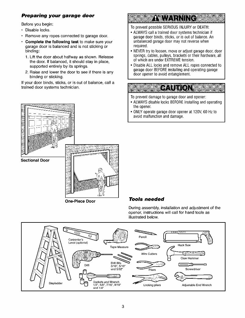
• Complete the following test to make sure yourgarage door is balanced and is not sticking orbinding:
1 Lift the door about halfway as shown. Releasethe door. If balanced, it should stay in place,supported entirely by its springs.
2 Raise and lower the door to see if there is anybinding or sticking
If your door binds, sticks, or is out of balance, call atrained door systems technician.
Sectional Door
To prevent possibleSERIOUSINJURY or DEATH:• ALWAYScall a trained door systems technician if
garage door binds, sticks, or is out of balance.Anunbalancedgaragedoor may not reversewhenrequired
• NEVERtry to loosen, move or adjust garage door, doorsprings, cables, pulleys, brackets or their hardware, allof which are under EXTREMEtension.
• DisableALL locks and remove ALL ropes connected togarage door BEFOREinstalling and operating garagedoor opener to avoid entanglement.
To preventdamage to garagedoor and opener:• ALWAYSdisable locks BEFOREinstalling and operating
the opener.• ONLYoperate garagedoor openerat 120V,60 Hz to
avoid malfunction and damage
One-Piece Door Tools needed
During assembly, installation and adjustment of theopener, instructions will call for hand tools asillustrated below.
Stepladder
Pencil
Level (optionml)
Tape MeasureHack Smw
Screwdriver
o)
Adjustable End Wrench
3
Planning
Identify the type and height of your garage door.Survey your garage area to see if any of theconditions below apply to your installation. Additionalmaterials may be required. You may find it helpful torefer back to this page and the accompanyingillustrations as you proceed with the installation ofyour opener.
Depending on your requirements, there are severalinstallation steps which may call for materials orhardware not included in the carton.
• Installation Step 1 - Look at the wall or ceilingabove the garage door. The header bracket mustbe securely fastened to structural supports.
• Installation Step 5 - Do you have a finished ceilingin your garage? If so, a support bracket andadditional fastening hardware may be required.
• Installation Step 10 - Depending upon garageconstruction, extension brackets or wood blocksmay be needed to install sensors.
• Installation Step 10 -Alternate floor mounting ofthe safety reversing sensor will require hardwarenot provided.
Do you have an access door in addition to thegarage door? If not, Model 53702 Emergency KeyRelease is required. See Accessories page.
Look at the garage door where it meets the floor.Any gap between the floor and the bottom of thedoor must not exceed 1/4" (6 mm). Otherwise, thesafety reversal system may not work properly. SeeAdjustment Step 3. Floor or door should berepaired.
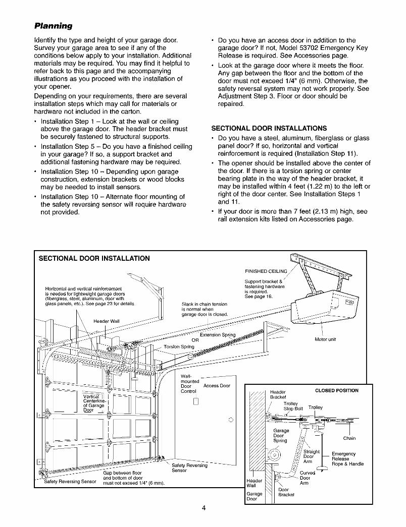
SECTIONAL DOOR INSTALLATIONS
Do you have a steel, aluminum, fiberglass or glasspanel door? If so, horizontal and verticalreinforcement is required (Installation Step 11).
The opener should be installed above the center ofthe door. If there is a torsion spring or centerbearing plate in the way of the header bracket, itmay be installed within 4 feet (1.22 m) to the left orright of the door center. See Installation Steps 1and 11.
• If your door is more than 7 feet (2.13 m) high, seerail extension kits listed on Accessories page.
SECTIONAL DOOR INSTALLATION
FINISHED CEILING
Horizontal and vertical reinforcement
is needed for lightweight garage doors(fiberglass, steel, aluminum, door withglass panels, etc.). See page 23 for details.
Header Wall
Slack in chain tensionis normal when
garage door is closed.
fastening hardwareis required.See page 16.
OR
f Torsion Spring
Motor unit
Wall-
DoorContro
Gap between floorand bottom of doormust not exceed 1/4" (6 mm).
Safety ReversingSensor
Access Door
}aderall
Header CLOSED POSITIONBracket
TrolleyStop Bolt Trolley
Garage
sOOn g ChainP g 2
o Straig Emergency_i_g _m °el Release
_ _id _ Rope& Handle
DoorArm
Door_rage)or
4
Planning (Continued)
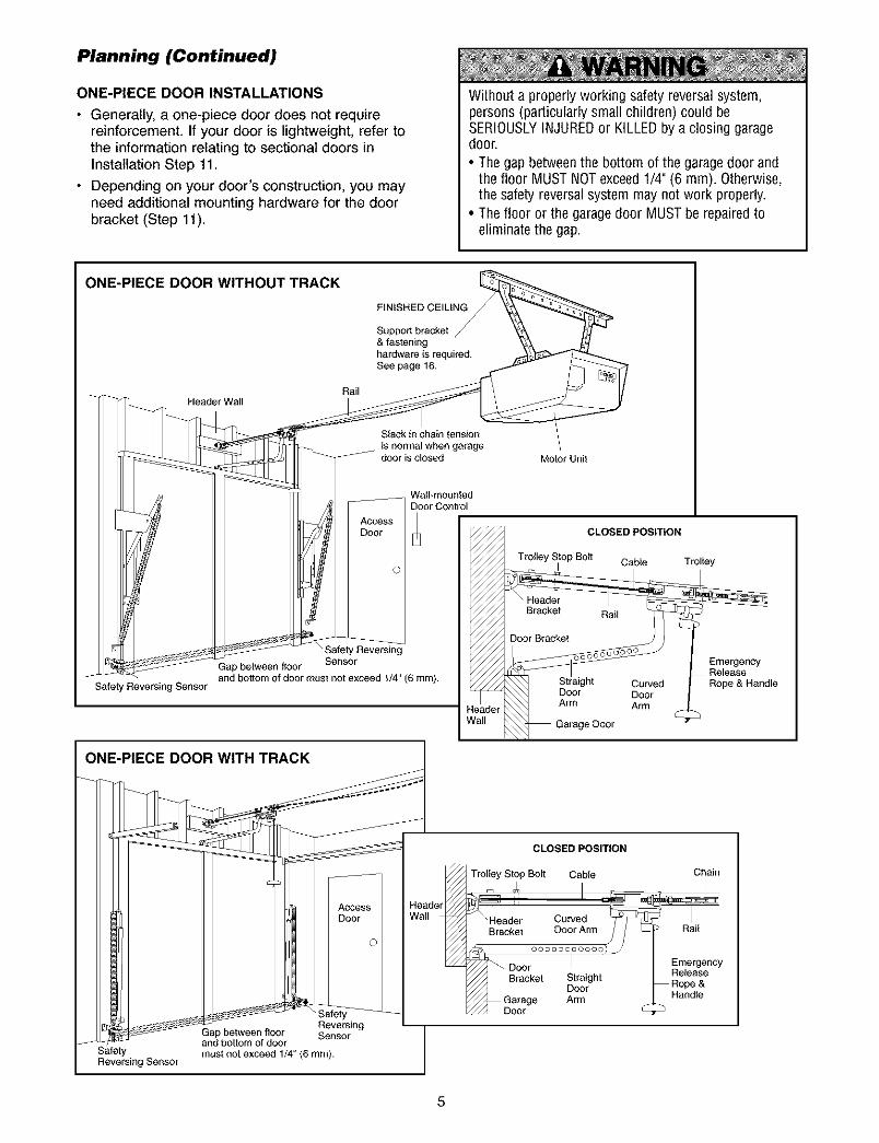
ONE-PIECE DOOR INSTALLATIONS
• Generally, a one-piece door does not requirereinforcement. If your door is lightweight, refer tothe information relating to sectional doors inInstallation Step 11.
• Depending on your door's construction, you mayneed additional mounting hardware for the doorbracket (Step 11).
Without a properly working safety reversalsystem,persons (particularly small children) could beSERIOUSLYINJUREDor KILLEDby a closing garagedoor.
• The gap betweenthe bottom of the garagedoor andthe floor MUST NOTexceed 1/4" (6 ram). Otherwise,the safety reversalsystem may not work properly.
• The floor or the garagedoor MUST be repairedtoeliminate the gap.
ONE-PIECE DOOR WITHOUT TRACK
FINISHED CEILING
Support bracket& fasteninghardware is required.See page 16.
Safety Reversing Sensor
Rail
Slack in chain tension
is normal when garagedoor is closed
Wail-mountedDoor Control
Safety Reversing
Gap between floor Sensor
and bottom of door must not exceed 1/4" (6 rnm).
Motor Unit
Trolley Stop Bolt
eader/atl
CLOSED POSITION
cable Trolley
EmergencyRelease
Rope & Handle
ONE-PIECE DOOR WITH TRACK
SafetyReversing Sensor
Access IDoor I
()1
Revel*singGap between floor Sensorand bottom of doormust not exceed 1/4" (6 mm).
CLOSED POSITION
Trolley Stop Bolt Cable
Header Cu_'edBracket Door Ar
_D °°°°°°°©°
Door I
Bracket StraightDoor
Garage Armoct
Chain
Rail
Eme_encyReleaseRope &Handle
5
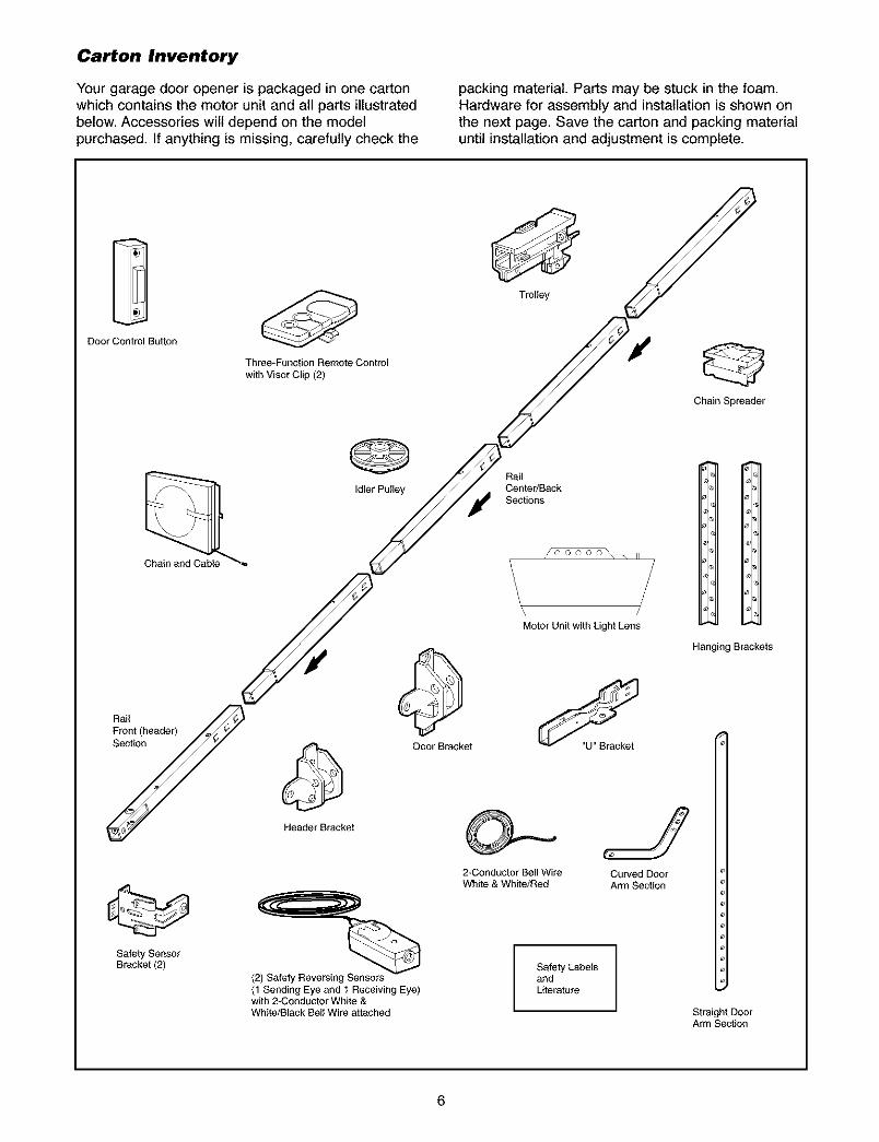
Carton Inventory
Your garage door opener is packaged in one cartonwhich contains the motor unit and all parts illustratedbelow. Accessories wilt depend on the modelpurchased. If anything is missing, carefully check the
packing material. Parts may be stuck in the foam.Hardware for assembly and installation is shown onthe next page. Save the carton and packing materialuntil installation and adjustment is complete.
Door Control Button
Three*Function Remote Control
with Visor Clip (2)
Trolley
Chain Spreader
Idler Pulley
RailCentedBackSections
H
Motor Unit with Light Lens
Hanging Brackets
Rraoln!(header)._
YSafety SensorBracket (2)
Door Bracket
HeaderBracket
(2) Safety Reversing_
(1 Sending Eye and I Receiving Eye)with 2-Conductor White &White/Black Bell Wire attached
2-Conductor Bell WireWhite & White/Red
"U" Bracket
Curved DoorArm Section
Safety LabelsandLiterature
Straight DoorArm Section
6
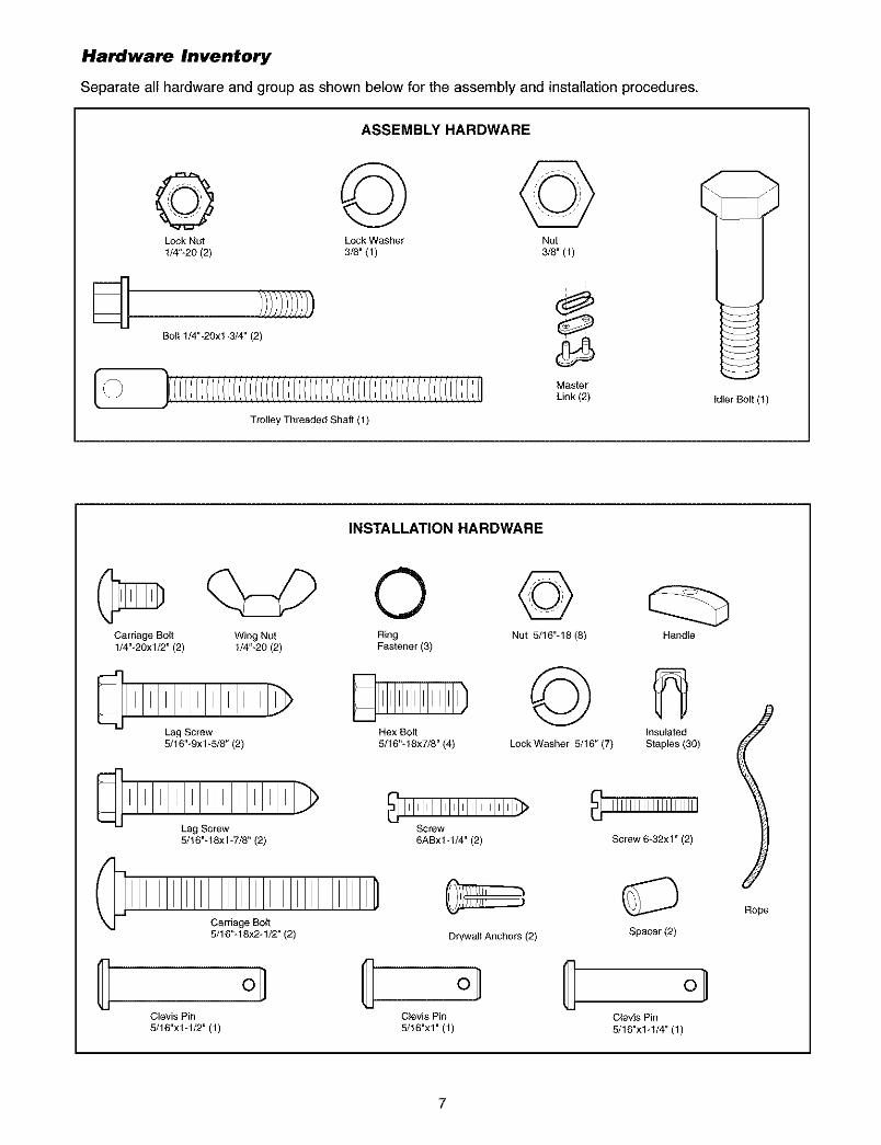
Hardware Inventory
Separate all hardware and group as shown below for the assembly and installation procedures.
ASSEMBLY HARDWARE
© @ ©Lock Nut Lock Washer Nut
1/4"-20 (2) 3/8" (1) 3/8" (1)
Bolt 1/4"-20x1-314" (2)
Trolley Threaded Shaft (1)
INSTALLATION HARDWARE
i
Master
Link (2) Idler Bolt (1)
Carriage Bolt1/4"-20xl/2" (2)
Wing Nut Ring Nut 5/16"q8 (8)1/4"-20 (2) Fastener (3)
Lag Screw Hex Bolt5/16"_9x1_5/8" (2) 5/16"_18x7/8" (4)
Lag Screw Screw5/16"-18x1_7/8" (2) 6ABxl-1/4" (2)
©LockWasher 5/16" (7)
Handle
InsulatedStaples (30)
Screw 6-32xl" (2)
Carriage Bolt5/16"q 8x2q/2" (2) Drywall Anchors (2) Spacer (2)
Clevis Pin Clevis Pin Clevis Pin
5/16"x1-1/2" (1) 5/16"x1" (1) 5/16"x1-1/4" (1)
lRope
7
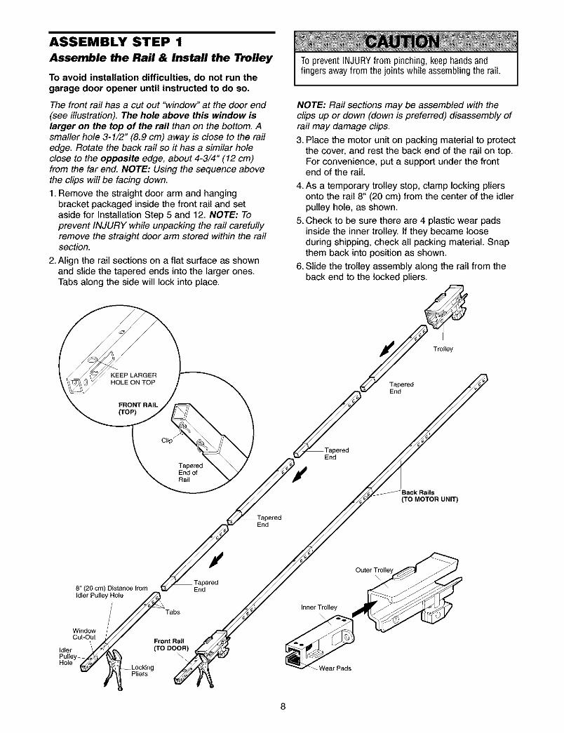
ASSEMBLY STEP 1
Assemble the Rail & Install the l_olley
To avoid installation difficulties, do not run thegarage door opener until instructed to do so.
The front rail has a cut out "window" at the door end(see illustration). The hole above this window islarger on the top of the rail than on the bottom. Asmaller hole 3-1/2" (8.9 cm) away is close to the railedge. Rotate the back rail so it has a similar holeclose to the opposite edge, about 4-3/4" (12 cm)from the far end. NOTE: Using the sequence abovethe clips will be facing down.
1. Remove the straight door arm and hangingbracket packaged inside the front rail and setaside for Installation Step 5 and 12. NOTE: Toprevent INJURY while unpacking the rail carefullyremove the straight door arm stored within the railsection.
2. Align the rail sections on a flat surface as shownand slide the tapered ends into the larger ones.Tabs along the side will lock into place.
To prevent INJURYfrom pinching, keep hands andfingers away from the joints while assembling the rail.
NOTE: Rail sections may be assembled with theclips up or down (down is preferred) disassembly ofrail may damage clips.
3. Place the motor unit on packing material to protectthe cover, and rest the back end of the rail on top.For convenience, put a support under the frontend of the rail.
4. As a temporary trolley stop, clamp locking pliersonto the rail 8" (20 cm) from the center of the idlerpulley hole, as shown.
5. Check to be sure there are 4 plastic wear padsinside the inner trolley. If they became looseduring shipping, check all packing material. Snapthem back into position as shown.
6. Slide the trolley assembly along the rail from theback end to the locked pliers.
KEEP LARGERHOLE ON TOP
FRONT RAIL(TOP)
Clip"
TaperedEnd ofRail
End
Trolley
TaperedEnd
(TO MOTOR UNIT)
End
8" (20 cm) Distance from Endidler Pulley Hole
Tabs
WindowCutOut
\ Front RailIdler (TO DOOR)
Inner Trolley
Wear Pads
Outer Trolley
8
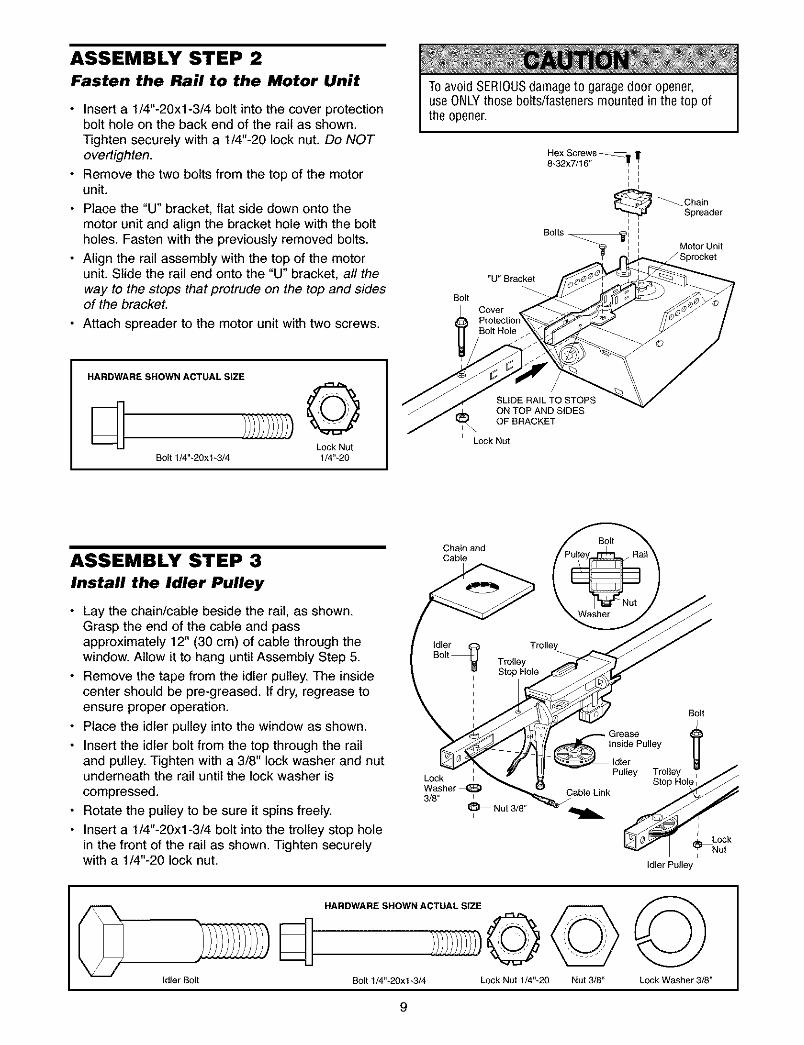
ASSEMBLY STEP 2Fasten the Rail to the Motor Unit
• Insert a 1/4"-20xl-3/4 bolt into the cover protectionbolt hole on the back end of the rail as shown.Tighten securely with a 1/4"-20 lock nut. Do NOTovertighten.
• Remove the two bolts from the top of the motorunit.
• Place the "U" bracket, flat side down onto themotor unit and align the bracket hole with the boltholes. Fasten with the previously removed bolts.
• Align the rail assembly with the top of the motorunit. Slide the rail end onto the "U" bracket, all theway to the stops that protrude on the top and sidesof the bracket.
• Attach spreader to the motor unit with two screws.
To avoid SERIOUSdamage to garagedoor opener,use ONLYthose bolts/fasteners mounted in the top ofthe opener.
Bolt
Hex Screws _==_o8-32x7/16" 11I"
I II i
Bolts -
"U" Bracket
Cover
I _ Chain
Spreader
Motor Unit_Sprecket
HARDWARE SHOWN ACTUAL SIZE
©Lock Nut
Bolt 1/4"-20x1-3/4 1/4"-20
SLIDE RAIL TO STOPSON TOP AND SIDESOF BRACKET
Lock Nut
ASSEMBLY STEP 3
Install the Idler Pulley
• Lay the chain/cable beside the rail, as shown.Grasp the end of the cable and passapproximately 12" (30 cm) of cable through thewindow. Allow it to hang until Assembly Step 5.
• Remove the tape from the idler pulley. The insidecenter should be pre-greased. If dry, regrease toensure proper operation.
• Place the idler pulley into the window as shown.
• Insert the idler bolt from the top through the railand pulley. Tighten with a 3/8" lock washer and nutunderneath the rail until the lock washer iscompressed.
• Rotate the pulley to be sure it spins freely.
• Insert a 1/4"-20xl-3/4 bolt into the trolley stop holein the front of the rail as shown. Tighten securelywith a 1/4"-20 lock nut.
Chain andCable
Trolley
LockWasher3/8"
I_1 Nut 3/8"
Bolt
GreaseInside Pulley
Idler
Pulley Trolley
Stop HOl,
Cable Link /
I
Lock
_utIdler Pulley
Idler Bolt
HARDWARE SHOWN ACTUAL SIZE
Bolt 1/4"-20xl-3/4 Lock Nut 1/4"-20 Nut 3/8" Lock Washer 3/8"
9
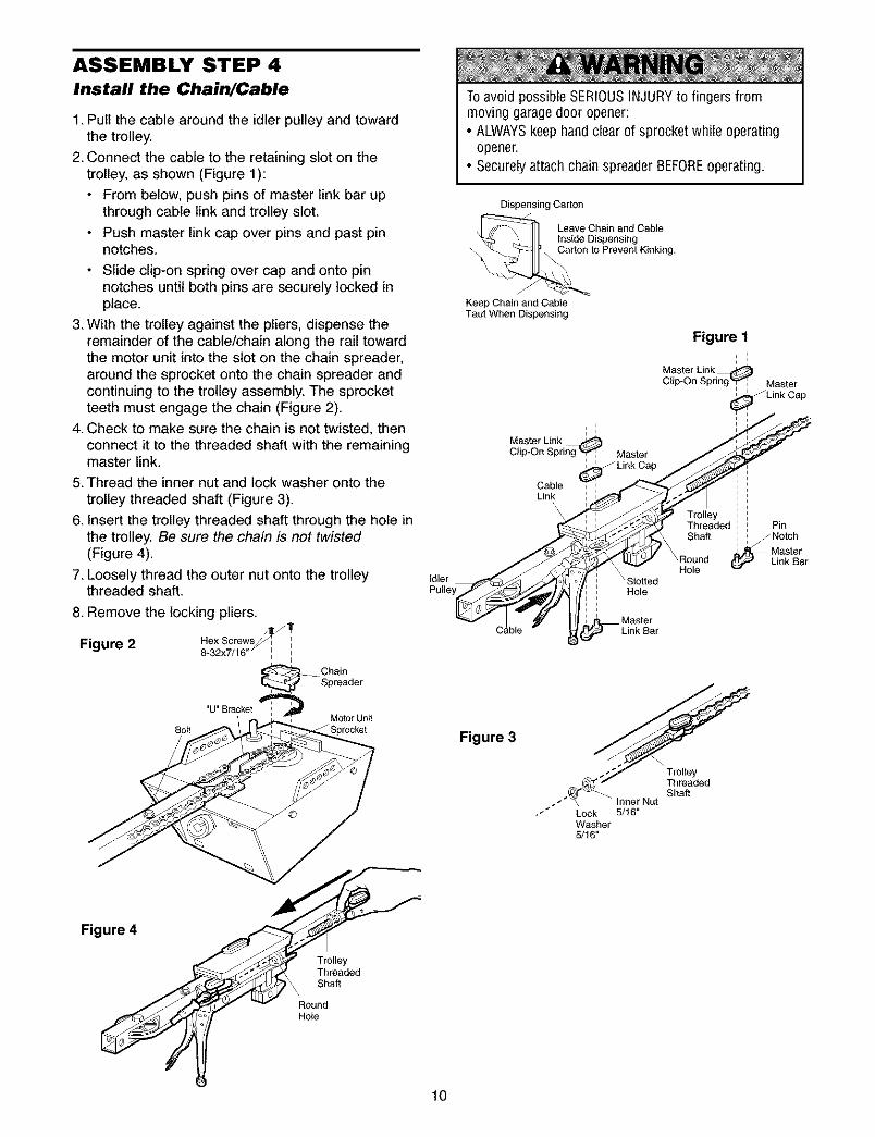
ASSEMBLY STEP 4Install the Chain/Cable
1. Pull the cable around the idler pulley and towardthe trolley.
2. Connect the cable to the retaining slot on thetrolley, as shown (Figure 1):
• From below, push pins of master link bar upthrough cable link and trolley slot.
• Push master link cap over pins and past pinnotches.
• Slide clip-on spring over cap and onto pinnotches until both pins are securely locked inplace.
3. With the trolley against the pliers, dispense theremainder of the cable/chain along the rail towardthe motor unit into the slot on the chain spreader,around the sprocket onto the chain spreader andcontinuing to the trolley assembly. The sprocketteeth must engage the chain (Figure 2).
4. Check to make sure the chain is not twisted, thenconnect it to the threaded shaft with the remainingmaster link.
5. Thread the inner nut and lock washer onto thetrolley threaded shaft (Figure 3).
6. insert the trolley threaded shaft through the hole inthe trolley. Be sure the chain is not twisted(Figure 4).
7. Loosely thread the outer nut onto the trolleythreaded shaft.
8. Remove the locking pliers.
Figure 2 RexScrews_8-32x7/16" :
ChainSpreader
"U" Bracket :MOtOrUnit
Bolt
To avoid possible SERIOUSINJURYto fingers frommoving garage door opener:• ALWAYSkeep handclear of sprocket while operating
opener.• Securely attach chain spreader BEFOREoperating.
Dispensing Carton
Leave Chain and CableInside Dispensing
to Prevent Kinking.
Keep Chain and CableTaut When Dispensing
Figure 1, :i
Master Link _LinkClip-On Spring_ Master
Capo j
clip.onSpri Master
Cable : :Link : , /
, , Trolley_ : , Threaded : P n
_ Shaft , _ Notch_ __ Master
" Hole Link Bar
Idler _,__ F _ Sl-otted Hole '
o,ey O : r
Figure 3
,eadedShaft" Inner Nut
•J Lock 5/16"Washer5/16"
Figure 4
TrolleyThreadedShaft
RoundHole
lO
ASSEMBLY STEP 5
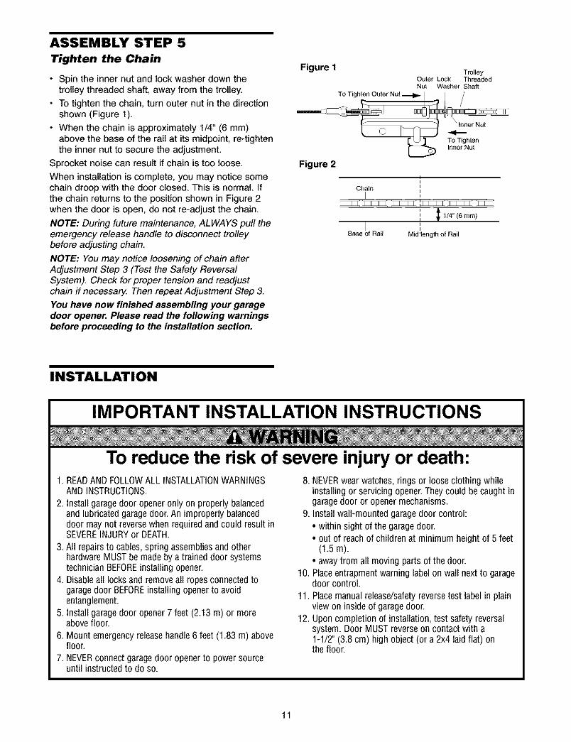
Tighten the Chain
• Spin the inner nut and lock washer down thetrolley threaded shaft, away from the trolley.
• To tighten the chain, turn outer nut in the directionshown (Figure 1).
• When the chain is approximately 1/4" (6 mm)above the base of the rail at its midpoint, re-tightenthe inner nut to secure the adjustment.
Sprocket noise can result if chain is too loose.
When installation is complete, you may notice somechain droop with the door closed. This is normal. Ifthe chain returns to the position shown in Figure 2when the door is open, do not re-adjust the chain.
NOTE: During future maintenance, ALWAYS pull theemergency release handle to disconnect trolleybefore adjusting chain.
NOTE: You may notice loosening of chain afterAdjustment Step 3 (Test the Safety ReversalSystem). Check for proper tension and readjustchain if necessar_ Then repeat Adjustment Step 3.
You have now finished assembling your garagedoor opener. Please read the following warningsbefore proceeding to the installation section.
Figure I TrolleyOuter Lock ThreadedNut Washer Shaft
TO Tighten Outer Nut
Figure 2
TO TightenInner Nut
Chain i
I
Base of Rail Mid!length of Rail
INSTALLATION
IMPORTANT INSTALLATION INSTRUCTIONS
To reduce the risk of severe injury or death:1. READAND FOLLOWALL INSTALLATIONWARNINGS
AND INSTRUCTIONS.
2. Install garage door opener only on properly balancedand lubricated garagedoor. An improperly balanceddoor may not reversewhen required and could result inSEVEREINJURY or DEATH.
3. All repairs to cables, spring assembliesand otherhardware MUST be made by a trained door systemstechnician BEFOREinstalling opener.
4. Disableall locks and remove all ropes connected togaragedoor BEFOREinstalling opener to avoidentanglement.
5. Install garage door opener 7 feet (2.13 m) or moreabove floor.
6. Mount emergency releasehandle 6 feet (1.83 m) abovefloor.
7. NEVERconnect garage door opener to power sourceuntil instructed to do so.
8. NEVERwear watches, rings or loose clothing whileinstalling or servicing opener.Theycould be caught ingarage door or opener mechanisms.
9. Install wall-mounted garagedoor control:• within sight of the garage door.• out of reach of children at minimum height of 5 feet
(1.5m).• away from all moving parts of the door.
10. Placeentrapment warning label on wall next to garagedoor control.
11. Place manual release/safetyreversetest label in plainview on inside of garage door.
12. Upon completion of installation, test safety reversalsystem. Door MUST reverseon contact with a1-1/2" (3.8 cm) high object (or a 2x4 laid flat) onthe floor.
11
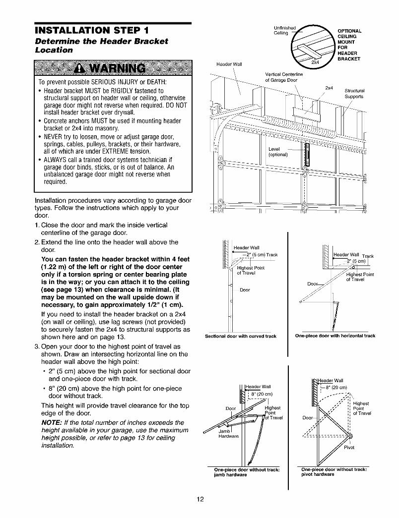
INSTALLATION STEP 1Determine the Header BracketLocation
To prevent possible SERIOUSINJURY or DEATH:• Header bracket MUST be RIGIDLYfastened to
structural support on headerwall or ceiling, otherwisegarage door might not reversewhen required. DONOTinstall header bracket over drywall.
• Concrete anchors MUST be used if mounting headerbracket or 2x4 into masonry.
• NEVERtry to loosen, move or adjust garage door,springs, cables, pulleys, brackets, or their hardware,all of which are under EXTREMEtension.
• ALWAYScall a trained door systems technician ifgarage door binds, sticks, or is out of balance.Anunbalanced garagedoor might not reversewhenrequired.
Installation procedures vary according to garage doortypes. Follow the instructions which apply to yourdoor.
1. Close the door and mark the inside verticalcenterline of the garage door.
2. Extend the line onto the header wall above thedoor.
You can fasten the header bracket within 4 feet(1.22 m) of the left or right of the door centeronly if a torsion spring or center bearing plateis in the way; or you can attach it to the ceiling(see page 13) when clearance is minimal. (Itmay be mounted on the wall upside down ifnecessary, to gain approximately 1/2" (1 cm).
If you need to install the header bracket on a 2x4(on wall or ceiling), use lag screws (not provided)to securely fasten the 2x4 to structural supports asshown here and on page 13.
3. Open your door to the highest point of travel asshown. Draw an intersecting horizontal line on theheader walt above the high point:
• 2" (5 cm) above the high point for sectional doorand one-piece door with track.
• 8" (20 cm) above the high point for one-piecedoor without track.
This height wilt provide travel clearance for the topedge of the door.NOTE: If the total number of inches exceeds theheight available in your garage, use the maximumheight possible, or refer to page 13 for ceilinginstallation.
Header Wall
Unfinishe_
Ceilin OPTIONALg CEILING
MOUNTFORHEADER
BRACKET
Vertical Centerline
of Garage Door
2x4Structural
Suppods
Header Wal_"--'--2" (5 cm) Track
of Travel
Door
Sectional door with curved track
4eader Wall Track
/f Highest Pointof Travel
One-piece door with horizontal track
_0 ci_)HeaderWall
Doer __ _!igihl!;tel
One-piece door without track:jamb hardware
Header Wall
Pivot
One-piece door without track:pivot hardware
12
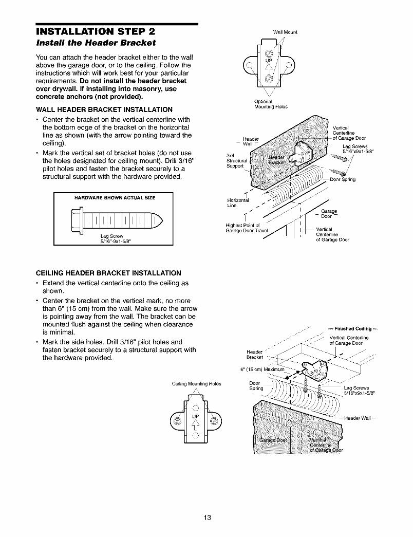
INSTALLATION STEP 2Install the Header Bracket
You can attach the header bracket either to the wallabove the garage door, or to the ceiling. Follow theinstructions which will work best for your particularrequirements. Do not install the header bracketover drywall. If installing into masonry, useconcrete anchors (not provided).
WALL HEADER BRACKET INSTALLATION
• Center the bracket on the vertical centerline withthe bottom edge of the bracket on the horizontalline as shown (with the arrow pointing toward theceiling).
• Mark the vertical set of bracket holes (do not usethe holes designated for ceiling mount). Drill 3/16"pilot holes and fasten the bracket securely to astructural support with the hardware provided.
HARDWARESHOWNACTUALSIZE
Lag Screw5/16"-9xl-5/8"
Wall Mount
OptionalMounting Holes
HeaderWall
2x4StructuralSupport
/
HorizontalLine / /
/
Highest Point ofGarage Door Travel
Ve_icalCenterline
Door
Lag Screws5/16"x9x1-5/8"
DoorSp#ng
f
GarageDoor
Centetline
of Garage Door
CEILING HEADER BRACKET INSTALLATION
• Extend the vertical centerline onto the ceiling asshown.
• Center the bracket on the vertical mark, no morethan 6" (15 cm) from the walt. Make sure the arrowis pointing away from the wall. The bracket can bemounted flush against the ceiling when clearanceis minimal.
• Mark the side holes. Drill 3/16" pilot holes andfasten bracket securely to a structural support withthe hardware provided.
Ceiling Mounting Holes
Header /
Bracket
6" (15 cm) Maximum
DoorSpring
_J
Lag Screws
5/16"x9x1-5/8"
Header Wall
13
Header Bracket
Idler Pulley
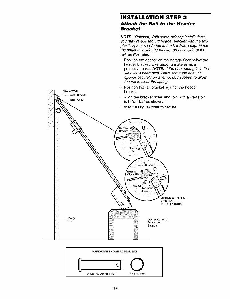
INSTALLATION STEP 3Attach the Rail to the HeaderBracket
NOTE: (Optional) With some existing installations,you may re-use the old header bracket with the twoplastic spacers included in the hardware bag. Placethe spacers inside the bracket on each side of therail, as illustrated.
• Position the opener on the garage floor below theheader bracket. Use packing material as aprotective base. NOTE: If the door spring is in theway you'll need help. Have someone hold theopener securely on a temporary support to allowthe rail to clear the spring.
• Position the rail bracket against the headerbracket.
• Align the bracket holes and join with a clevis pin5/16"xl-1/2" as shown.
• Insert a ring fastener to secure.
0
MountingHole
Header Bracket
0
MountingHote
OPTION WITH SOMEEXISTINGINSTALLATIONS
GarageDoor Opener Carton or
Suppod
HARDWARE SHOWN ACTUAL SIZE
C 0Clevis Pin 5/16" x 1-1/2" Ring fastener
14
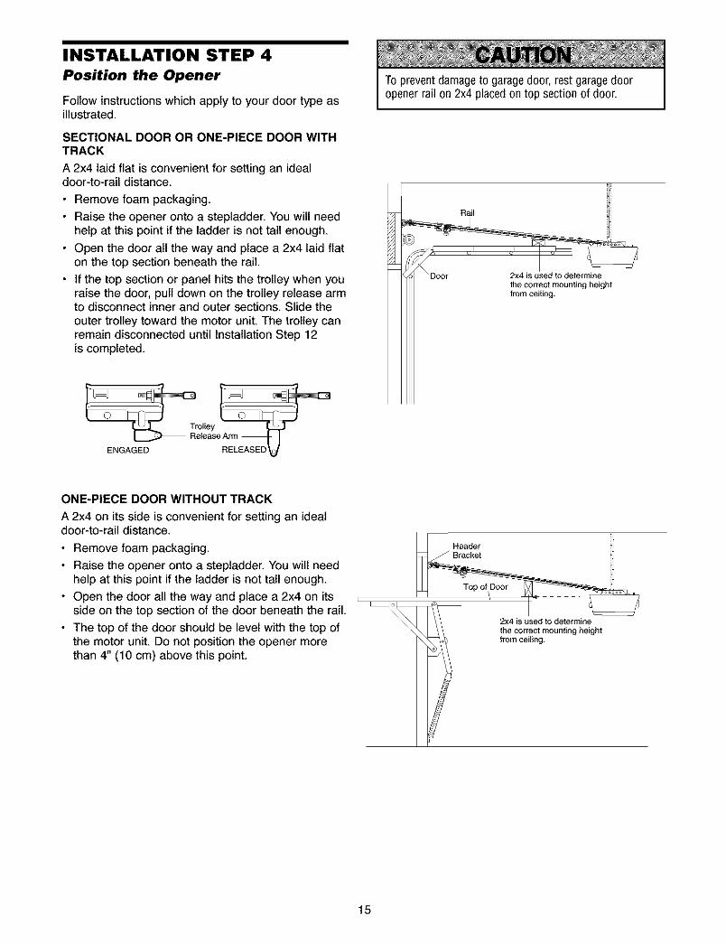
INSTALLATION STEP 4Position the Opener
Follow instructions which apply to your door type asillustrated.
SECTIONAL DOOR OR ONE-PIECE DOOR WITHTRACK
A 2x4 laid flat is convenient for setting an idealdoor-to-rail distance.
• Remove foam packaging.
• Raise the opener onto a stepladder. You will needhelp at this point if the ladder is not tall enough.
• Open the door all the way and place a 2x4 laid flaton the top section beneath the rail.
• If the top section or panel hits the trolley when youraise the door, pull down on the trolley release armto disconnect inner and outer sections. Slide theouter trolley toward the motor unit. The trolley canremain disconnected until Installation Step 12is completed.
To prevent damage to garage door, rest garage dooropener rail on 2x4 placed on top section of door.
Rail
2x4 is used to determine
the correct mounting heightfrom ceiling.
ENGAGED
ONE-PIECE DOOR WITHOUT TRACK
A 2x4 on its side is convenient for setting an idealdoor-to-rail distance.
• Remove foam packaging.
• Raise the opener onto a stepladder. You will needhelp at this point if the ladder is not tall enough.
• Open the door all the way and place a 2x4 on itsside on the top section of the door beneath the rail.
• The top of the door should be level with the top ofthe motor unit. Do not position the opener morethan 4" (10 cm) above this point.
_ 2x4 is used to determine
the correct mounting heightfrom ceiling.
15
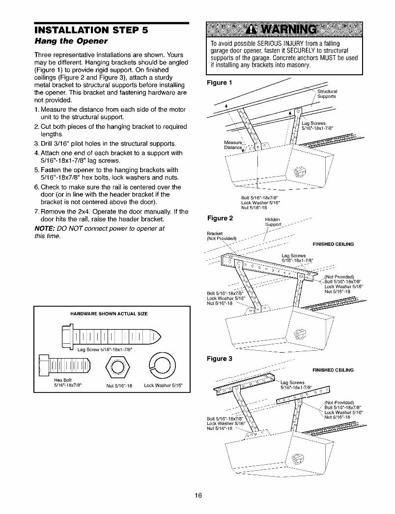
INSTALLATION STEP 5Hang the Opener
Three representative installations are shown. Yoursmay be different. Hanging brackets should be angled(Figure 1) to provide rigid support. On finishedceilings (Figure 2 and Figure 3), attach a sturdymetal bracket to structural supports before installingthe opener. This bracket and fastening hardware arenot provided.1. Measure the distance from each side of the motor
unit to the structural support.
2. Cut both pieces of the hanging bracket to requiredlengths.
3. Drill 3/16" pilot holes in the structural supports.
4. Attach one end of each bracket to a support with5/16"-18xl -7/8" lag screws.
5. Fasten the opener to the hanging brackets with5/16"-18x7/8" hex bolts, lock washers and nuts.
6. Check to make sure the rail is centered over thedoor (or in line with the header bracket if thebracket is not centered above the door).
7. Remove the 2x4. Operate the door manually. If thedoor hits the rail, raise the header bracket.
NOTE: DO NOT connect power to opener atthis time.
HARDWARE SHOWN ACTUAL SIZE
Hex Bolt5/16"- 18x7/6"
©©Nut 5/16"q8 Lock Washer 5/16"
To avoid possible SERIOUSINJURYfrom a fallinggarage door opener,fasten it SECURELYto structuralsupports of the garage. Concrete anchors MUST be usedif installing any brackets into masonry.
Figure 1
/ Suppo_s
Measure_Distance
Lag Screws5/16"-18xl-7/8"
Bolt 5/16"-18x7/6"Lock Washer 5/16"Nut 5/16"-16
Figure 2 Hidden __"
Bracket z _ - -(Not Provided) _ _--"" - _ _ .- _
FINISHED CEIUNG
Lag Screws5/16"-18x 1-7/8"
Bott 5/16"- 18x7/8"Lock Washer 5/16"Nut 5/16"-18
%I%--
/(Not Provided)Bolt 5/! 6"-18x7/8"
r 5/16"Nut 6/16"-18
Figure 3
-" -- _ -- -_" FINISHED CEILING
X ,_ _L_.,_- _ _(NotProvided)
_ Oo _ Lock Washer 6/16"Bott 5/16"-18x7/8" ° Nut 5/16"-18
Livou_k_/_sher 5/16 ....
16
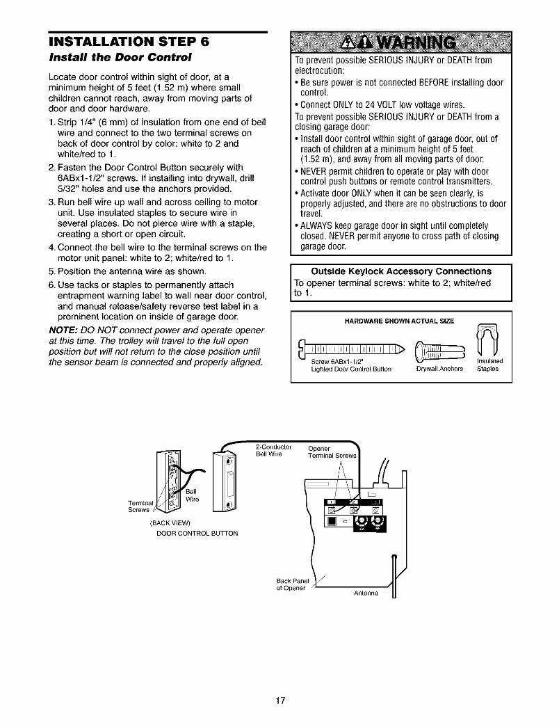
INSTALLATION STEP 6Install the Door Control
Locate door control within sight of door, at aminimum height of 5 feet (1.52 m) where smallchildren cannot reach, away from moving parts ofdoor and door hardware.
1. Strip 1/4" (6 mm) of insulation from one end of bellwire and connect to the two terminal screws onback of door control by color: white to 2 andwhite/red to 1.
2. Fasten the Door Control Button securely with6ABx1-1/2" screws. If installing into drywall, drill5/32" holes and use the anchors provided.
3. Run bell wire up walt and across ceiling to motorunit. Use insulated staples to secure wire inseveral places. Do not pierce wire with a staple,creating a short or open circuit.
4. Connect the bell wire to the terminal screws on themotor unit panel: white to 2; white/red to 1.
5. Position the antenna wire as shown.
6. Use tacks or staples to permanently attachentrapment warning label to wall near door control,and manual release/safety reverse test label in aprominent location on inside of garage door.
NOTE: DO NOT connect power and operate openerat this time. The trolley will travel to the full openposition but will not return to the close position untilthe sensor beam is connected and properly aligned.
To prevent possible SERIOUSINJURY or DEATHfromelectrocution:
• Be sure power is not connected BEFOREinstalling doorcontrol.
• Connect ONLYto 24 VOLTlow voltage wires.To prevent possible SERIOUSINJURY or DEATHfrom aclosing garagedoor:• Install door control within sight of garage door, out of
reach of children at a minimum height of 5 feet
• (1.52 m), and away from all moving parts of door.NEVERpermit children to operate or play with doorcontrol push buttons or remote control transmitters.
• Activate door ONLYwhen it can be seen clearly, isproperly adjusted, and there are no obstructions to doortravel.
• ALWAYSkeep garagedoor in sight until completelyclosed. NEVERpermit anyone to cross path of closinggaragedoor.
Outside Keylock Accessory Connections
To lo.pener terminal screws: white to 2; white/red
HARDWARE SHOWN ACTUAL SIZE
''''''''''''> n oatedLighted Door Control Button D_ywatl Anchors Staples
Bell
Tern_inat WireScrews
(BACK VIEW)
DOOR CONTROL BUTTON
2*ConductorBell Wire
OpenerTerminal Screws
Back Panel J
of Opener
17
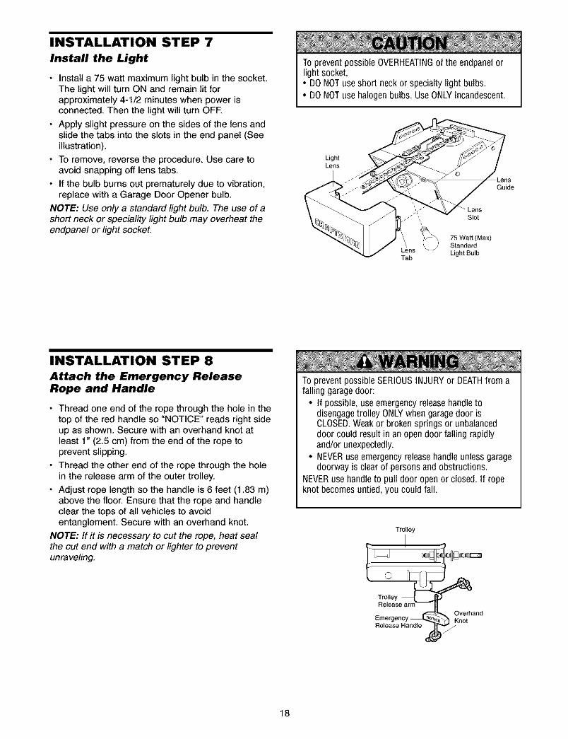
INSTALLATION STEP 7
Install the Light
• Install a 75 watt maximum light bulb in the socket.The light will turn ON and remain lit forapproximately 4-1/2 minutes when power isconnected. Then the light will turn OFR
• Apply slight pressure on the sides of the lens andslide the tabs into the slots in the end panel (Seeillustration).
• To remove, reverse the procedure. Use care toavoid snapping off lens tabs.
• If the bulb burns out prematurely due to vibration,replace with a Garage Door Opener bulb.
NOTE: Use only a standard light bulb. The use of ashort neck or speciality light bulb may overheat theendpanel or light socket.
To prevent possible OVERHEATINGof the endpanel orlight socket,• DONOTuse short neck or specialty light bulbs.• DONOTuse halogen bulbs. UseONLYincandescent.
LightLens
Guide
Lens_" Slot
75 Watt (Max)
StandardLens Light BulbTab
INSTALLATION STEP 8
Attach the Emergency ReleaseRope and Handle
• Thread one end of the rope through the hole in thetop of the red handle so "NOTICE" reads right sideup as shown. Secure with an overhand knot atleast 1" (2.5 cm) from the end of the rope toprevent slipping.
• Thread the other end of the rope through the holein the release arm of the outer trolley.
• Adjust rope length so the handle is 6 feet (1.83 m)above the floor. Ensure that the rope and handleclear the tops of all vehicles to avoidentanglement. Secure with an overhand knot.
NOTE: If it is necessary to cut the rope, heat sealthe cut end with a match or lighter to preventunraveling.
To prevent possible SERIOUSINJURYor DEATHfrom afalling garage door:
• If possible, use emergency releasehandletodisengage trolley ONLYwhen garagedoor isCLOSED.Weak or broken springs or unbalanceddoor could result in an open door falling rapidlyand/or unexpectedly.
• NEVERuse emergency releasehandle unless garagedoorway is clear of persons and obstructions.
NEVERuse handle to pull door open or closed. If ropeknot becomes untied, you could fall.
Trolley
Enlergency _ _) KOnVe[band
Release Handle _,
18
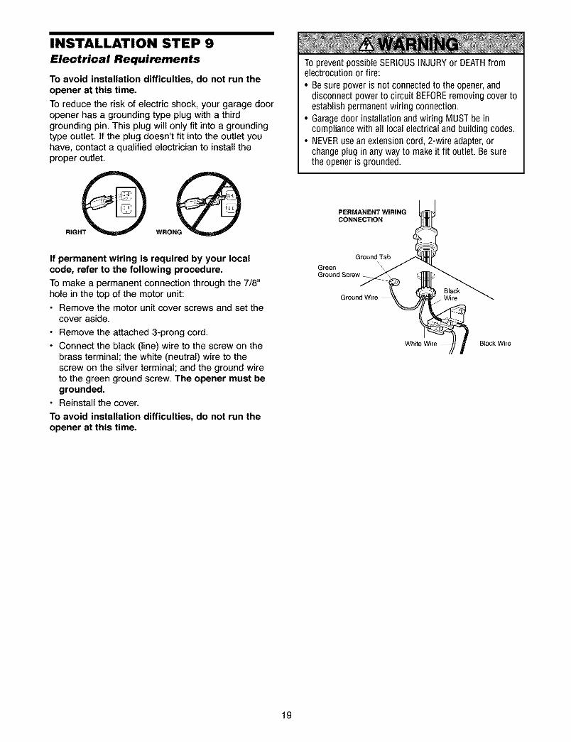
INSTALLATION STEP 9
Electrical Requirements
To avoid installation difficulties, do not run theopener at this time.
To reduce the risk of electric shock, your garage dooropener has a grounding type plug with a thirdgrounding pin. This plug will only fit into a groundingtype outlet. If the plug doesn't fit into the outlet youhave, contact a qualified electrician to install theproper outlet.
RIGHT
To prevent possible SERIOUSINJURY or DEATHfromelectrocution or fire:
• Be sure poweris not connected to the opener,anddisconnect power to circuit BEFOREremoving cover toestablish permanent wiring connection.
• Garagedoor installation and wiring MUST be incompliance with all local electrical and building codes.
• NEVERuse an extension cord, 2-wire adapter, orchange plug in any way to make it fit outlet. Be surethe opener is grounded.
PERMANENT WIRINGCONNECTION
If permanent wiring is required by your localcode, refer to the following procedure.
To make a permanent connection through the 7/8"hole in the top of the motor unit:• Remove the motor unit cover screws and set the
cover aside.
• Remove the attached 3-prong cord.
• Connect the black (line) wire to the screw on thebrass terminal; the white (neutral) wire to thescrew on the silver terminal; and the ground wireto the green ground screw. The opener must begrounded.
• Reinstall the cover.
To avoid installation difficulties, do not run theopener at this time.
Ground Tab
GreenGround Screw
Ground Wire
19
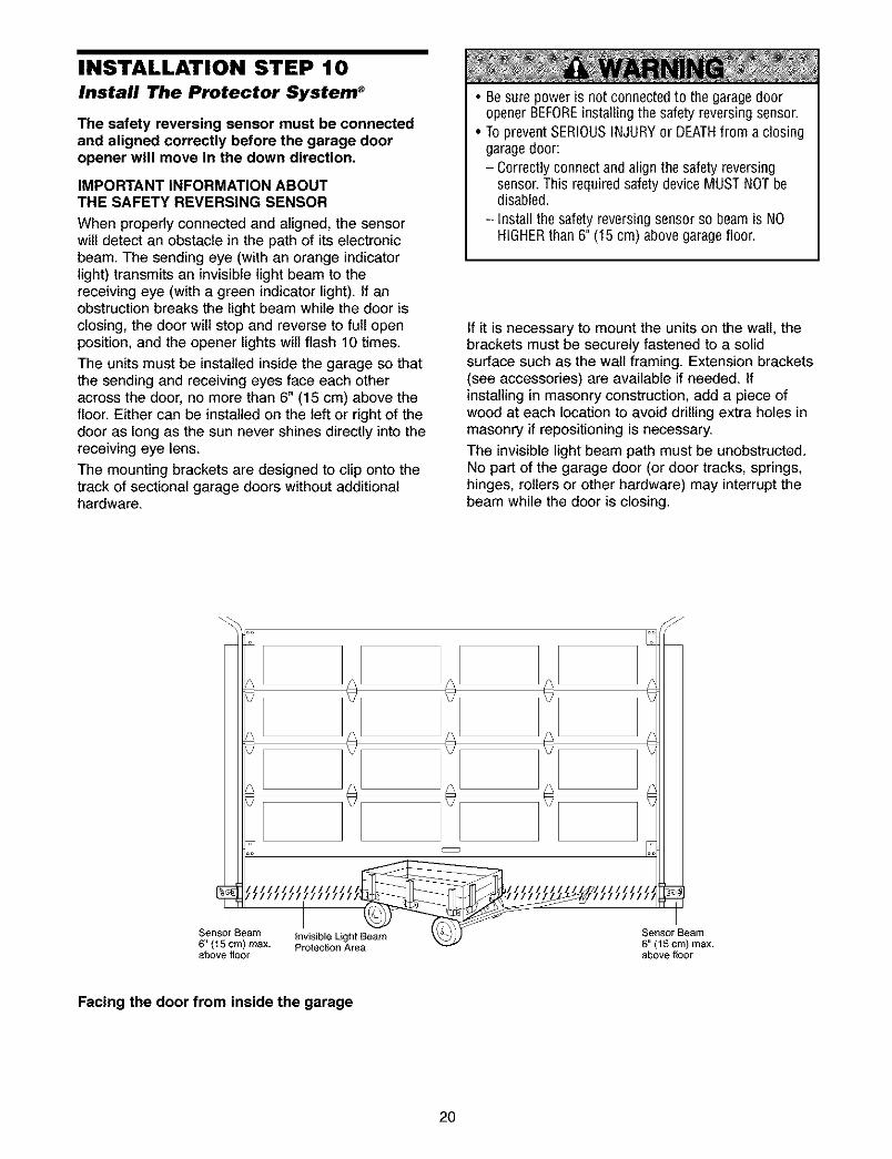
INSTALLATION STEP 10Install The Protector System _
The safety reversing sensor must be connectedand aligned correctly before the garage dooropener will move in the down direction.
IMPORTANT INFORMATION ABOUTTHE SAFETY REVERSING SENSOR
When properly connected and aligned, the sensorwill detect an obstacle in the path of its electronicbeam. The sending eye (with an orange indicatorlight) transmits an invisible light beam to thereceiving eye (with a green indicator light). If anobstruction breaks the light beam while the door isclosing, the door will stop and reverse to full openposition, and the opener lights will flash 10 times.
The units must be installed inside the garage so thatthe sending and receiving eyes face each otheracross the door, no more than 6" (15 cm) above thefloor. Either can be installed on the left or right of thedoor as long as the sun never shines directly into thereceiving eye lens.
The mounting brackets are designed to clip onto thetrack of sectional garage doors without additionalhardware.
• Besure poweris not connected to the garagedooropener BEFOREinstalling the safety reversing sensor.
• To prevent SERIOUSINJURYor DEATHfrom a closinggaragedoor:- Correctly connect and align the safety reversing
sensor. This required safety device MUST NOTbedisabled.
- Install the safety reversing sensor so beam is NOHIGHERthan 6" (15 cm) above garage floor.
If it is necessary to mount the units on the wall, thebrackets must be securely fastened to a solidsurface such as the wall framing. Extension brackets(see accessories) are available if needed. Ifinstalling in masonry construction, add a piece ofwood at each location to avoid drilling extra holes inmasonry if repositioning is necessary.
The invisible light beam path must be unobstructed.No part of the garage door (or door tracks, springs,hinges, rollers or other hardware) may interrupt thebeam while the door is closing.
6" (15 crn) max. Protection Areaabove floor
Sensor Beam
6" (15 cm) max.above f_oor
Facing the door from inside the garage
2O
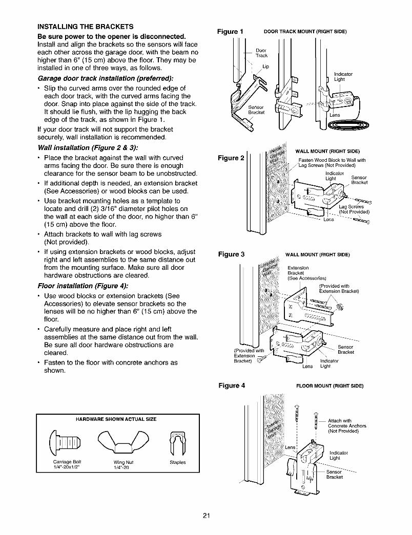
INSTALLING THE BRACKETS
Be sure power to the opener is disconnected.Install and align the brackets so the sensors will faceeach other across the garage door, with the beam nohigher than 6" (15 cm) above the floor. They may beinstalled in one of three ways, as follows.
Garage door track installation (preferred):
• Slip the curved arms over the rounded edge ofeach door track, with the curved arms facing thedoor. Snap into place against the side of the track.It should lie flush, with the lip hugging the backedge of the track, as shown in Figure 1.
If your door track wilt not support the bracketsecurely, wall installation is recommended.
Wall installation (Figure 2 & 3):
• Place the bracket against the wall with curvedarms facing the door. Be sure there is enoughclearance for the sensor beam to be unobstructed.
• If additional depth is needed, an extension bracket(See Accessories) or wood blocks can be used.
• Use bracket mounting holes as a template tolocate and drill (2) 3/16" diameter pilot holes onthe walt at each side of the door, no higher than 6"(15 cm) above the floor.
• Attach brackets to wall with lag screws(Not provided).
• if using extension brackets or wood blocks, adjustright and left assemblies to the same distance outfrom the mounting surface. Make sure all doorhardware obstructions are cleared.
Floor installation (Figure 4):
• Use wood blocks or extension brackets (SeeAccessories) to elevate sensor brackets so thelenses will be no higher than 6" (15 cm) above thefloor.
• Carefully measure and place right and leftassemblies at the same distance out from the wall.Be sure all door hardware obstructions arecleared.
• Fasten to the floor with concrete anchors asshown.
Figure 1 DOORTRACKMOUNT
DoorTrack
Sensor _ ::_Bracket
RIGHT SIDE)
IndicatorLight
Figure 2WALL MOUNT (RIGHT SIDE)
Fasten Wood Block to Wall with/Lag Screws (Not Provided)
IndicatorLight Sensor
Bracket
Figure 3 WALL MOUNT (RIGHT SIDE)
ExtensionBracket(See Accessories)
(Provided withExtension Bracket)
(Provided withExtensionBracket) _" Indicator
Lens Light
SeRsorBracket
Figure 4 FLOOR MOUNT (RIGHT SIDE)
HARDWARE SHOWN ACTUAL SIZE
Carriage Bolt Wing Nut Staples1/4"-20xl/2" 1/4"-20
J
i Attach withConcrete Anchors
; (Not Provided)
Indicator
Light
21
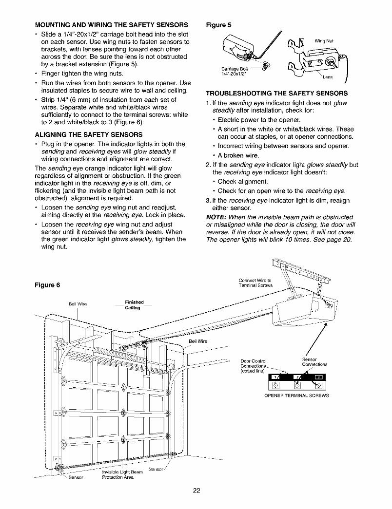
MOUNTING AND WIRING THE SAFETY SENSORS
• Slide a 1/4"-20xl/2" carriage bolt head into the sloton each sensor. Use wing nuts to fasten sensors tobrackets, with lenses pointing toward each otheracross the door. Be sure the lens is not obstructedby a bracket extension (Figure 5).
• Finger tighten the wing nuts.
• Run the wires from both sensors to the opener. Useinsulated staples to secure wire to wall and ceiling.
• Strip 1/4" (6 mm) of insulation from each set ofwires. Separate white and white/black wiressufficiently to connect to the terminal screws: whiteto 2 and white/black to 3 (Figure 6).
ALIGNING THE SAFETY SENSORS
• Plug in the opener. The indicator lights in both thesending and receiving eyes will glow steadily ifwiring connections and alignment are correct.
The sending eye orange indicator light will glowregardless of alignment or obstruction. If the greenindicator light in the receiving eye is off, dim, orflickering (and the invisible light beam path is notobstructed), alignment is required.
• Loosen the sending eye wing nut and readjust,aiming directly at the receiving eye. Lock in place.
• Loosen the receiving eye wing nut and adjustsensor until it receives the sender's beam. Whenthe green indicator light glows steadily, tighten thewing nut.
Figure 5
TROUBLESHOOTING THE SAFETY SENSORS
1. If the sending eye indicator light does not glowsteadily after installation, check for:
• Electric power to the opener.• A short in the white or white/black wires. These
can occur at staples, or at opener connections.
• Incorrect wiring between sensors and opener.• A broken wire.
2. If the sending eye indicator light glows steadily butthe receiving eye indicator light doesn't:
• Check alignment.
• Check for an open wire to the receiving eye.
3. If the receiving eye indicator light is dim, realigneither sensor.
NOTE: When the invisible beam path is obstructedor misaligned while the door is closing, the door willreverse. If the door is already open, it will not close.The opener lights will blink 10 times. See page 20.
Figure 6Connect Wire toTerminal Screws
Bell Wire Finished
Ceiling
Bell Wire
DoorControlConnections
(do_edline) _
/SensorConnections
OPENER TERMINAL SCREWS
\ Sensor
Sensor_Invisible Light BeamProtec_onArea
22
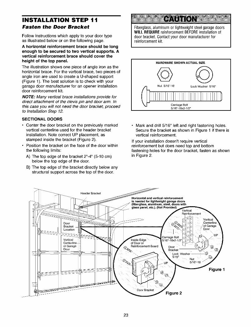
INSTALLATION STEP 11Fasten the Door Bracket
Follow instructions which apply to your door typeas illustrated below or on the following page.
A horizontal reinforcement brace should be longenough to be secured to two vertical supports. Avertical reinforcement brace should cover theheight of the top panel.
The illustration shows one piece of angle iron as thehorizontal brace. For the vertical brace, two pieces ofangle iron are used to create a U-shaped support(Figure 1). The best solution is to check with yourgarage door manufacturer for an opener installationdoor reinforcement kit.
NOTE: Many vertical brace installations provide fordirect attachment of the clevis pin and door arm. Inthis case you will not need the door bracket; proceedto Installation Step 12.
SECTIONAL DOORS
• Center the door bracket on the previously markedvertical centerline used for the header bracketinstallation. Note correct UP placement, asstamped inside the bracket (Figure 2).
• Position the bracket on the face of the door withinthe following limits:
A) The top edge of the bracket 2"-4" (5-10 cm)below the top edge of the door.
B) The top edge of the bracket directly below anystructural support across the top of the door.
Fiberglass,aluminum or lightweight steel garagedoorsWill. REQUIREreinforcement BEFOREinstallation ofdoor bracket. Contactyour door manufacturer forreinforcement kit.
HARDWARE SHOWN ACTUAL SIZE
© ©Nut 5/16"_18 LockWasher 5/16"
Carnage Bolt5/16"_18x2-1/2"
• Mark and drill 5/16" left and right fastening holes.Secure the bracket as shown in Figure 1 if there isvertical reinforcement.
If your installation doesn't require verticalreinforcement but does need top and bottomfastening holes for the door bracket, fasten as shownin Figure 2.
HeaderBracket
Horizontal and vertical reinforcement
is needed for lightweight garage doors(fiberglass, aluminum, steel, doors with
Vertical
Figure 1
ure 2
23
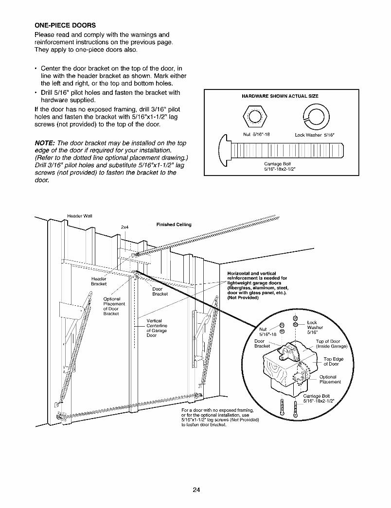
ONE-PIECE DOORS
Please read and comply with the warnings andreinforcement instructions on the previous page.They apply to one-piece doors also.
• Center the door bracket on the top of the door, inline with the header bracket as shown. Mark eitherthe left and right, or the top and bottom holes.
• Drill 5/16" pilot holes and fasten the bracket withhardware supplied.
If the door has no exposed framing, drill 3/16" pilotholes and fasten the bracket with 5/16"x1-1/2" lagscrews (not provided) to the top of the door.
NOTE: The door bracket may be installed on the topedge of the door if required for your installation.(Refer to the dotted line optional placement drawing.)Drill 3/16" pilot holes and substitute 5/16"xl- 1/2" lagscrews (not provided) to fasten the bracket to thedoor.
HARDWARE SHOWN ACTUAL SIZE
© ©Nut 5/16"-18 LockWasher 5/f6"
Carriage Bolt5/16"-18x2*f/2"
Header Wall
2x4 Finished Ceiling
Horizontal and verticalreinforcement is needed for
doors(fiberglass, aluminum, steel,door with glass panel, etc.).(Not Provided)
For a door with no exposed framing,or for the optional installation, use5/16"x1-f/2" lag screws (Not Provided)to fasten door bracket.
24
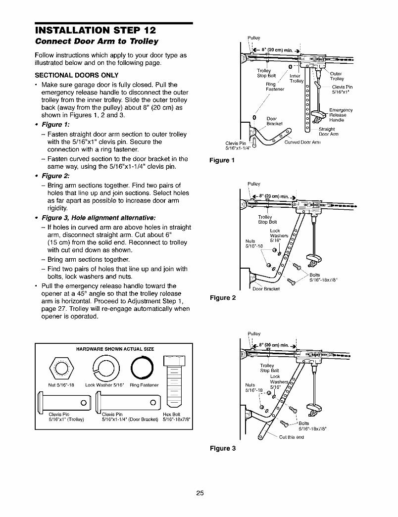
INSTALLATION STEP 12Connect Door Arm to Trolley
Follow instructions which apply to your door type asillustrated below and on the following page.
SECTIONAL DOORS ONLY
• Make sure garage door is fully closed. Pull theemergency release handle to disconnect the outertrolley from the inner trolley. Slide the outer trolleyback (away from the pulley) about 8" (20 cm) asshown in Figures 1, 2 and 3.
• Figure 1:
- Fasten straight door arm section to outer trolleywith the 5/16"xl" clevis pin. Secure theconnection with a ring fastener.
- Fasten curved section to the door bracket in thesame way, using the 5/16"xl-1/4" clevis pin.
• Figure 2:
- Bring arm sections together. Find two pairs ofholes that line up and join sections. Select holesas far apart as possible to increase door armrigidity.
• Figure 3, Hole alignment alternative:
- If holes in curved arm are above holes in straightarm, disconnect straight arm. Cut about 6"(15 cm) from the solid end. Reconnect to trolleywith cut end down as shown.
- Bring arm sections together.
- Find two pairs of holes that line up and join withbolts, lock washers and nuts.
• Pull the emergency release handle toward theopener at a 45° angle so that the trolley releasearm is horizontal. Proceed to Adjustment Step 1,page 27. Trolley wilt re-engage automatically whenopener is operated.
Pulley
L.- 'i i
8" (20 cm) rain. -)1
....Trolley /Stop Bolt Inner
/ Tr°llr Y I _ii121
Ring Clevis PinFastener 5/t6"xt"
Emergency
Door Handle
: Bracket oLoLo_¢_St j:: dIe_ Door Arm
Clevis Pin Curved Door Arm5/t6°xt.i__
Figure 1
Figure 2
Pulley
Bolts5/t6"-t8x7/8"
DoorBracket
HARDWARE SHOWN ACTUAL SIZE
©©0Nut 5/16"-18 Lock Washer 5/16" Ring Fastener
C °lC olClevis Pin Clevis Pin Hex Bolt5/16"x1" (Trolley) 5/16"x1-t/4" (Door Bracket) 5/16"-18x7/8"
Figure 3
Pulley
/ 4[..8" (20 cm) min...)i
%FP / '
5%.t8x,,8.
25
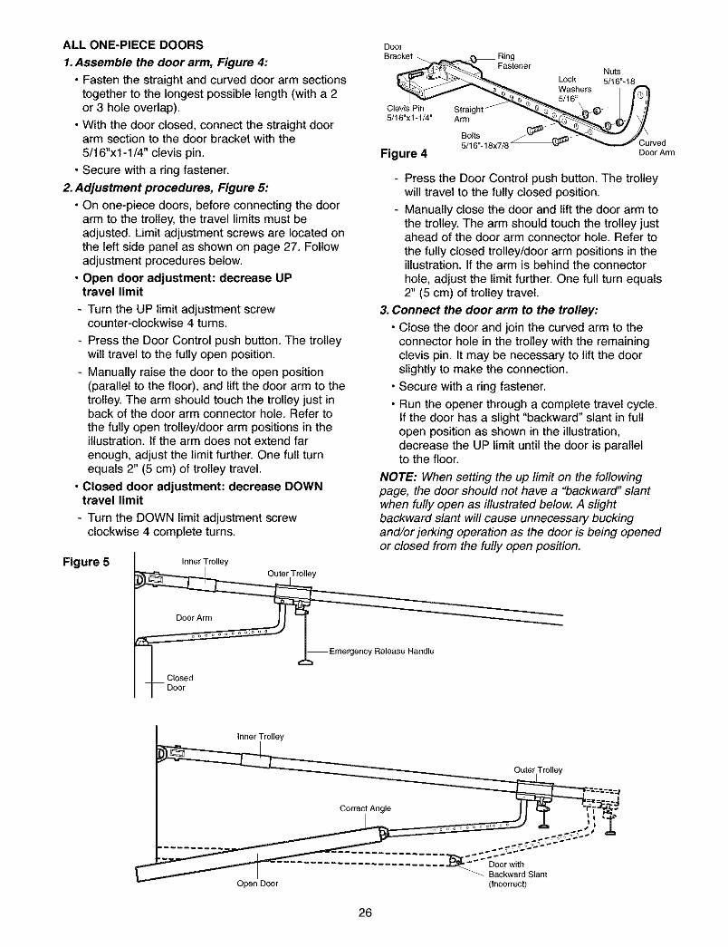
ALL ONE-PIECE DOORS
1.Assemble the door arm, Figure 4:
• Fasten the straight and curved door arm sectionstogether to the longest possible length (with a 2or 3 hole overlap).
• With the door closed, connect the straight doorarm section to the door bracket with the5/16"xl -1/4" clevis pin.
• Secure with a ring fastener.
2. Adjustment procedures, Figure 5:
• On one-piece doors, before connecting the doorarm to the trolley, the travel limits must beadjusted. Limit adjustment screws are located onthe left side panel as shown on page 27. Followadjustment procedures below.
• Open door adjustment: decrease UPtravel limit
- Turn the UP limit adjustment screwcounter-clockwise 4 turns.
- Press the Door Control push button. The trolleywilt travel to the fully open position.
- Manually raise the door to the open position(parallel to the floor), and lift the door arm to thetrolley. The arm should touch the trolley just inback of the door arm connector hole. Refer tothe fully open trolley/door arm positions in theillustration. If the arm does not extend farenough, adjust the limit further. One full turnequals 2" (5 cm) of trolley travel.
• Closed door adjustment: decrease DOWNtravel limit
- Turn the DOWN limit adjustment screwclockwise 4 complete turns.
Figure 5
DoorBracket
Clevis Pin Straight5/16"x1-1/4" Arm
Fastener
LockWashers5/16"
Nuts5/16"-18
Figure 4
Bolts5/16"_18x7/8 Cuwed
DoorArm
- Press the Door Control push button. The trolleywill travel to the fully closed position.
- Manually close the door and lift the door arm tothe trolley. The arm should touch the trolley justahead of the door arm connector hole. Refer tothe fully closed trolley/door arm positions in theillustration. If the arm is behind the connectorhole, adjust the limit further. One full turn equals2" (5 cm) of trolley travel.
3. Connect the door arm to the trolley:
• Close the door and join the curved arm to theconnector hole in the trolley with the remainingclevis pin. It may be necessary to lift the doorslightly to make the connection.
• Secure with a ring fastener.
• Run the opener through a complete travel cycle.If the door has a slight "backward" slant in fullopen position as shown in the illustration,decrease the UP limit until the door is parallelto the floor.
NOTE: When setting the up limit on the followingpage, the door should not have a "backward' slantwhen fully open as illustrated below. A slightbackward slant will cause unnecessary buckingand/or jerking operation as the door is being openedor closed from the fully open position.
Inner Trolley
Outer Trolley
Door Arm
Emergency Release Handle
Closed
Inner Trolley
Outer Trolley
± _.ii-]:
Backward Slant
Open Door (Incorrect)
26
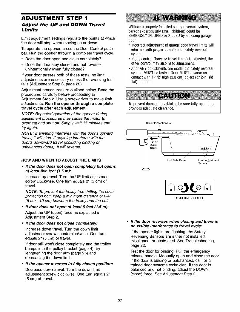
ADJUSTMENT STEP 1
Adjust the UP and DOWN TravelLimits
Limit adjustment settings regulate the points at whichthe door wilt stop when moving up or down.
To operate the opener, press the Door Control pushbar. Run the opener through a complete travel cycle.
• Does the door open and close completely?
• Does the door stay closed and not reverseunintentionally when fully closed?
If your door passes both of these tests, no limitadjustments are necessary unless the reversing testfails (Adjustment Step 3, page 29).
Adjustment procedures are outlined below. Read theprocedures carefully before proceeding toAdjustment Step 2. Use a screwdriver to make limitadjustments. Run the opener through a completetravel cycle after each adjustment.
NOTE: Repeated operation of the opener duringadjustment procedures may cause the motor tooverheat and shut oft Simply wait 15 minutes andtry again.
NOTE: If anything interferes with the door's upwardtravel, it will stop. If anything interferes with thedoor's downward travel (including binding orunbalanced doors), it will reverse.
HOW AND WHEN TO ADJUST THE LIMITS
• If the door does not open completely but opensat least five feet (1.5 m):
Increase up travel. Turn the UP limit adjustmentscrew clockwise. One turn equals 2" (5 cm) oftravel.
NOTE: To prevent the trolley from hitting the coverprotection bolt, keep a minimum distance of 2-4"(5 cm - 10 cm) between the trolley and the bolt.
• If door does not open at least 5 feet (1.5 m):
Adjust the UP (open) force as explained inAdjustment Step 2.
• If the door does not close completely:Increase down travel. Turn the down limitadjustment screw counterclockwise. One turnequals 2" (5 cm) of travel.
If door still won't close completely and the trolleybumps into the pulley bracket (page 4), trylengthening the door arm (page 25) anddecreasing the down limit.
• If the opener reverses in fully closed position:Decrease down travel. Turn the down limitadjustment screw clockwise. One turn equals 2"(5 cm) of travel.
Without a properlyinstalled safety reversal system,persons (particularly small children) could beSERIOUSLYINJUREDor KILLEDby a closing garagedoor.
• Incorrect adjustment of garagedoor travel limits willinterfere with proper operation of safety reversalsystem.
• If one control (force or travel limits) is adjusted, theother control mayalso needadjustment.
• After ANY adjustments are made, the safety reversalsystem MUST be tested. Door MUST reverseoncontact with 1-1/2" high (3.8 cm) object (or 2x4 laidflat) on floor.
To prevent damageto vehicles, besure fully open doorprovides adequateclearance.
Cover Protection Bolt
L _ _oo_ I
(5cm- I \t°cm) I \ *
/ vLeft Side Panel Limit Adjustment
Screws
If the door reverses when closing and there isno visible interference to travel cycle:
If the opener lights are flashing, the SafetyReversing Sensors are either not installed,misalgned, or obstructed. See Troubleshooting,page 22.
Test the door for binding: Pull the emergencyrelease handle. Manually open and close the door.If the door is binding or unbalanced, call for atrained door systems technician. If the door isbalanced and not binding, adjust the DOWN(close) force. See Adjustment Step 2.
27
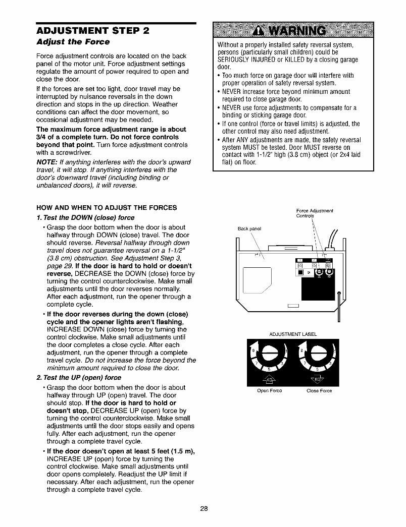
ADJUSTMENT STEP 2
Adjust the Force
Force adjustment controls are located on the backpanel of the motor unit. Force adjustment settingsregulate the amount of power required to open andclose the door.
If the forces are set too light, door travel may beinterrupted by nuisance reversals in the downdirection and stops in the up direction. Weatherconditions can affect the door movement, sooccasional adjustment may be needed.
The maximum force adjustment range is about3/4 of a complete turn. Do not force controlsbeyond that point. Turn force adjustment controlswith a screwdriver.
NOTE: If anything interferes with the door's upwardtravel, it will stop. If anything interferes with thedoor's downward travel (including binding orunbalanced doors), it will reverse.
Without a properly installed safety reversal system,persons (particularly small children) could beSERIOUSLYINJUREDor KILLEDby a closing garagedoor.
• Too much force on garagedoor will interfere withproper operation of safety reversalsystem.
• NEVERincreaseforce beyond minimum amountrequired to close garagedoor.
• NEVERuse force adjustments to compensatefor abinding or sticking garage door.
• If one control (force or travel limits) is adjusted, theother control may also needadjustment.
• After ANY adjustments are made, the safety reversalsystem MUST be tested. Door MUST reverseoncontact with 1-1/2" high (3.8 cm) object (or 2x4 laidflat) on floor.
HOW AND WHEN TO ADJUST THE FORCES
1. Test the DOWN (close) force
• Grasp the door bottom when the door is abouthalfway through DOWN (close) travel. The doorshould reverse. Reversal halfway through downtravel does not guarantee reversal on a 1-1/2"(3.8 cm) obstruction. See Adjustment Step 3,page 29. If the door is hard to hold or doesn'treverse, DECREASE the DOWN (close) force byturning the control counterclockwise. Make smalladjustments until the door reverses normally.After each adjustment, run the opener through acomplete cycle.
• If the door reverses during the down (close)cycle and the opener lights aren't flashing,INCREASE DOWN (close) force by turning thecontrol clockwise. Make small adjustments untilthe door completes a close cycle. After eachadjustment, run the opener through a completetravel cycle. Do not increase the force beyond theminimum amount required to close the door.
2. Test the UP (open) force
• Grasp the door bottom when the door is abouthalfway through UP (open) travel. The doorshould stop. If the door is hard to hold ordoesn't stop, DECREASE UP (open) force byturning the control counterclockwise. Make smalladjustments until the door stops easily and opensfully. After each adjustment, run the openerthrough a complete travel cycle.
• If the door doesn't open at least 5 feet (1.5 m),INCREASE UP (open) force by turning thecontrol clockwise. Make small adjustments untildoor opens completely. Readjust the UP limit ifnecessary. After each adjustment, run the openerthrough a complete travel cycle.
Force AdjustmentControls
Back panel
\
\l
ADJUSTMENT LABEL
Open Force Close Force
28
ADJUSTMENT STEP 3
Test the Safety Reversal System
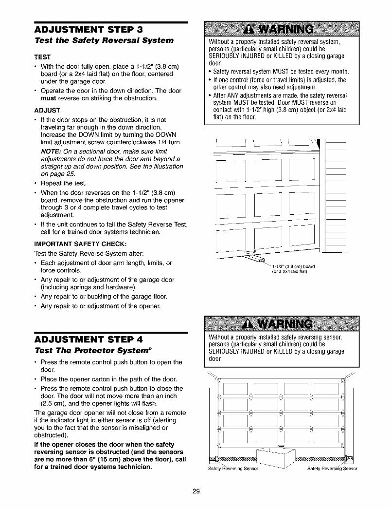
TEST
• With the door fully open, place a 1-1/2" (3.8 cm)board (or a 2x4 laid flat) on the floor, centeredunder the garage door.
• Operate the door in the down direction. The doormust reverse on striking the obstruction.
ADJUST
• If the door stops on the obstruction, it is nottraveling far enough in the down direction.Increase the DOWN limit by turning the DOWNlimit adjustment screw counterclockwise 1/4 turn.
NOTE: On a sectional door, make sure limitadjustments do not force the door arm beyond astraight up and down position. See the illustrationon page 25.
• Repeat the test.
• When the door reverses on the 1-1/2" (3.8 cm)board, remove the obstruction and run the openerthrough 3 or 4 complete travel cycles to testadjustment.
• If the unit continues to fail the Safety Reverse Test,call for a trained door systems technician.
IMPORTANT SAFETY CHECK:
Test the Safety Reverse System after:
• Each adjustment of door arm length, limits, orforce controls.
• Any repair to or adjustment of the garage door(including springs and hardware).
• Any repair to or buckling of the garage floor.
• Any repair to or adjustment of the opener.
Without a properly installed safety reversal system,persons (particularly small children) could beSERIOUSLYINJUREDor KILLEDby a closing garagedoor.
• Safety reversalsystem MUST be tested every month.• If one control (force or travel limits) is adjusted, the
other control may also needadjustment.• After ANY adjustments are made, the safety reversal
system MUST be tested. Door MUST reverseoncontact with 1-1/2" high (3.8 cm) object (or 2x4 laidflat) on the floor.
/, _1 _&
J
I 1/2 (38cm)board(or a 2x4 laid fiat)
ADJUSTMENT STEP 4
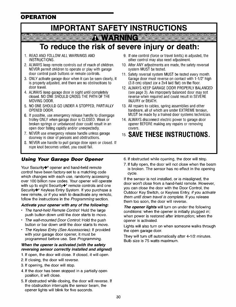
Test The Protector System _
• Press the remote control push button to open thedoor.
• Place the opener carton in the path of the door.
• Press the remote control push button to close thedoor. The door will not move more than an inch(2.5 cm), and the opener lights will flash.
The garage door opener will not close from a remoteif the indicator light in either sensor is off (alertingyou to the fact that the sensor is misaligned orobstructed).
If the opener closes the door when the safetyreversing sensor is obstructed (and the sensorsare no more than 6" (15 cm) above the floor), callfor a trained door systems technician.
Without a properly installed safety reversing sensor,persons (particularly small children) could beSERIOUSLYINJUREDor KILLEDby a closing garagedoor.
Safety Reversing Sensor
29
OPERATION
IMPORTANT SAFETY INSTRUCTIONS
To reduce the risk of severe injury or death:1. READAND FOLLOWALL WARNINGSAND
INSTRUCTIONS.
2. ALWAYSkeep remote controls out of reach of children.NEVERpermit children to operate or play with garagedoor control push buttons or remote controls.
3. ONLYactivategarage door when it can be seen clearly, itis properly adjusted, and there are no obstructions todoor travel.
4. ALWAYSkeep garagedoor in sight until completelyclosed. NO ONESHOULDCROSSTHEPATHOFTHEMOVINGDOOR.
5. NO ONESHOULDGOUNDERA STOPPED,PARTIALLYOPENEDDOOR.
6. If possible, use emergency release handleto disengagetrolley ONLYwhen garagedoor is CLOSED.Weakorbroken springs or unbalanced door could result in anopen door falling rapidly and/or unexpectedly.
7. NEVERuse emergency releasehandle unless garagedoorway is clear of personsand obstructions.
8. NEVERuse handleto pull garagedoor open or closed. Ifrope knot becomes untied, you could fall.
9. If one control (force or travel limits) is adjusted, theother control mayalso needadjustment.
10. After ANY adjustments are made, the safety reversalsystem MUST betested.
11. Safety reversalsystem MUST be tested every month.Garagedoor must reverseon contact with 1-1/2" high(3.8 cm) object (or a 2x4 laid flat) on the floor.
12. ALWAYSKEEPGARAGEDOORPROPERLYBALANCED(see page3). An improperly balanceddoor may notreversewhen required and could result in SEVEREINJURYor DEATH.
13. All repairs to cables, spring assemblies and otherhardware,all of which are under EXTREMEtension,MUST be made by a trained door systems technician.
14. ALWAYSdisconnect electric power to garage dooropenerBEFOREmaking any repairs or removingcovers.
15.SAVETHESEINSTRUCTIONS.
Using Your Garage Door Opener
Your Security÷ ®opener and hand-held remotecontrol have been factory-set to a matching codewhich changes with each use, randomly accessingover 100 billion new codes. Your opener will operatewith up to eight Security4 ,_ remote controls and oneSecurity÷ ® Keyless Entry System. If you purchase anew remote, or if you wish to deactivate any remote,follow the instructions in the Programming section.
Activate your opener with any of the following:• The hand-held Remote Control: Hold the large
push button down until the door starts to move.• The wall-mounted Door Control: Hold the push
button or bar down until the door starts to move.
• The Keyless Entry (See Accessories): If providedwith your garage door opener, it must beprogrammed before use. See Programming.
When the opener is activated (with the safetyreversing sensor correctly installed and aligned)
1. If open, the door will close. If closed, it wilt open.2. If closing, the door will reverse.
3. If opening, the door will stop.
4. If the door has been stopped in a partially openposition, it will close.
5. If obstructed while closing, the door will reverse, ifthe obstruction interrupts the sensor beam, theopener lights will blink for five seconds.
6. If obstructed while opening, the door will stop.7. If fully open, the door will not close when the beam
is broken. The sensor has no effect in the openingcycle.
If the sensor is not installed, or is misaligned, thedoor won't close from a hand-held remote. However,you can close the door with the Door Control, theOutdoor Key Switch, or Keyless Entry, if you activatethem until down travel is complete. If you releasethem too soon, the door will reverse.
The opener lights will turn on under the followingconditions: when the opener is initially plugged in;when power is restored after interruption; when theopener is activated.
Lights will also turn on when someone walks throughthe open garage door.
They will turn off automatically after 4-1/2 minutes.Bulb size is 75 watts maximum.
3O
Using the Wall.MountedDoor Control
Press the lighted push button to open or i_close the door. Press again to reverse I_] Ithe door during the closing cycle or to Istop the door while it's opening. ILl I
To Open the Door Manually
To prevent possible SERIOUSINJURYor DEATHfrom afalling garage door:
• If possible, use emergency releasehandletodisengage trolley ONLYwhen garagedoor isCLOSED.Weakor broken springs or unbalanceddoor could result in an open door falling rapidlyand/or unexpectedly.
• NEVERuse emergency releasehandle unless garagedoorway is clear of persons and obstructions.
NEVERuse handleto pull door open or closed. If ropeknot becomes untied, yOu could fall.
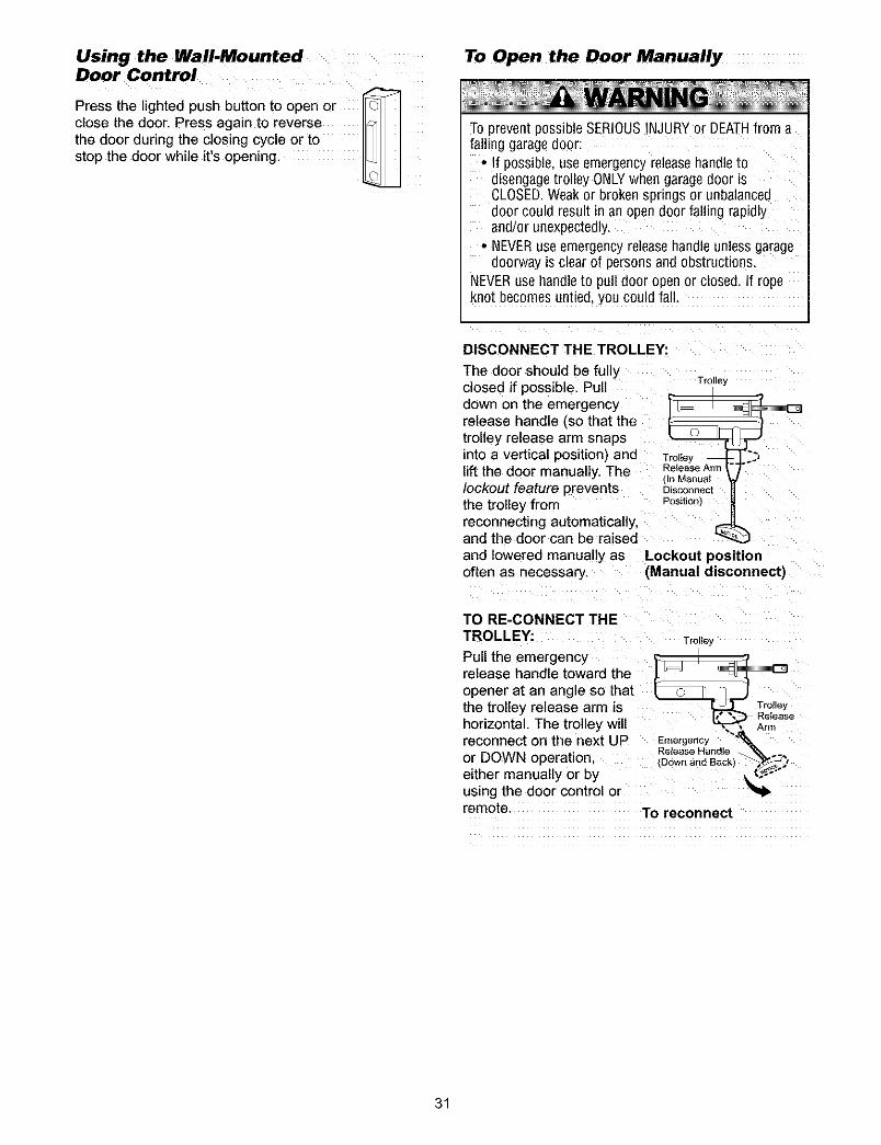
DISCONNECT THE TROLLEY:
The door should be fullyclosed if possible. Pulldown on the emergencyrelease handle (so that thetrolley release arm snapsinto a vertical position) andlift the door manually. Thelockout feature preventsthe trolley fromreconnecting automatically,and the door can be raised
and lowered manually asoften as necessary.
mrOll6j
Release ArmIn Manual
DisconnectPositiont
Lockout position(Manual disconnectl
TO RE-CONNECT THETROLLE_
Pull the emergencyrelease handle toward the
opener at an angle so thatthe trolley release arm ishorizontal. The trolley willreconnect on the next UPor DOWN operation.either manually or byusing the door control or
Trolle_
Emergency _,F_
remote. To reconnect
31
CARE OF YOUR OPENER
LIMIT AND FORCE ADJUSTMENTS:
Weather conditions may FORCECONTROLS
cause some minor changes _
in door operation requiringsome re-adjustments,particularly during the firstyear of operation.
Pages 27 and 28 refer to the LIMITCONTROLSlimit and force adjustments, z\ ,= =, z\Only a screwdriver is _ Q '_ _r (_)requ red. Fo ow the " _instructions carefully.
Repeat the safety reverse test (AdjustmentStep 3, page 29) after any adjustment of limits orforce.
THE REMOTE CONTROL BATTERY
,!f battery is swallowed, immediately notify doctor.
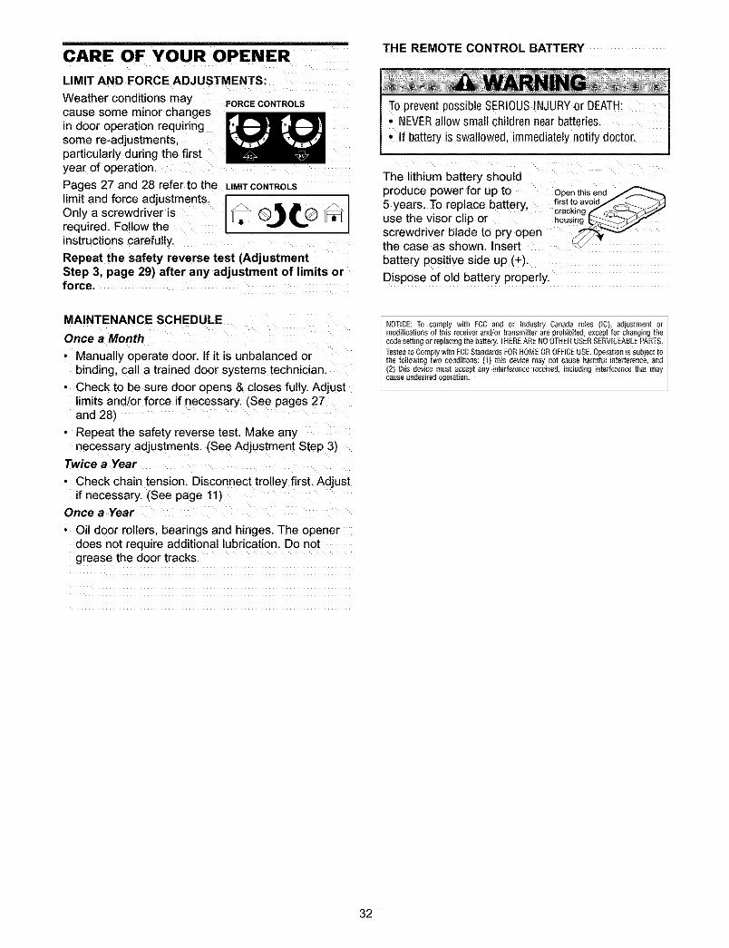
Z Z Z ZThe lithium battery shouldproduce power for up to Openthisend
5 years. To replace battery, firstt?avoidJ C_• . crackmg
use the visor chp or housing g _J
screwdriver blade to pry openthe case as shownl Insert _ "
battery positive side up (+).
Dispose of old battery properly.
MAINTENANCE SCHEDULE
Once a Month
• Manually operate door. If it is unbalanced orbinding, call a trained door systems technician.
• Check to be sure door opens & closes fully. Adjustlimits and/or force if necessary. (See pages 27and 28)
• Repeat the safety reverse test. Make anynecessary adjustments. (See Adjustment Step 3)
Twice a Year
• Check chain tension. Disconnect trolley first. Adjustif necessary. (See page 11)
Once a Year
• Oil door rollers, bearings and hinges. The openerdoes not require additional lubrication. Do notgrease the door tracks.
1NOTICE:To comply with FCC and or h]dusti_ Canada rules ([C), adjustment or [modifications of this receiverand/or transmitter are prohibited, exceptfor changingthecede setting or r_pl_cg_gthe battery.THEREARENO OTHERUSERSERVICEABLEPARTS.
the following two co_]ditiong:(f) this device may _]otcause harmful int_fere_]ce, a_dTestedto Complywith FCCStandardsFORNOMEOR OFFICEUSE.Operation issubject to
(2) this device must _ccept any intederence received, including interference that may
cause undes_edopela ion.
32
HAVING A PROBLEM?
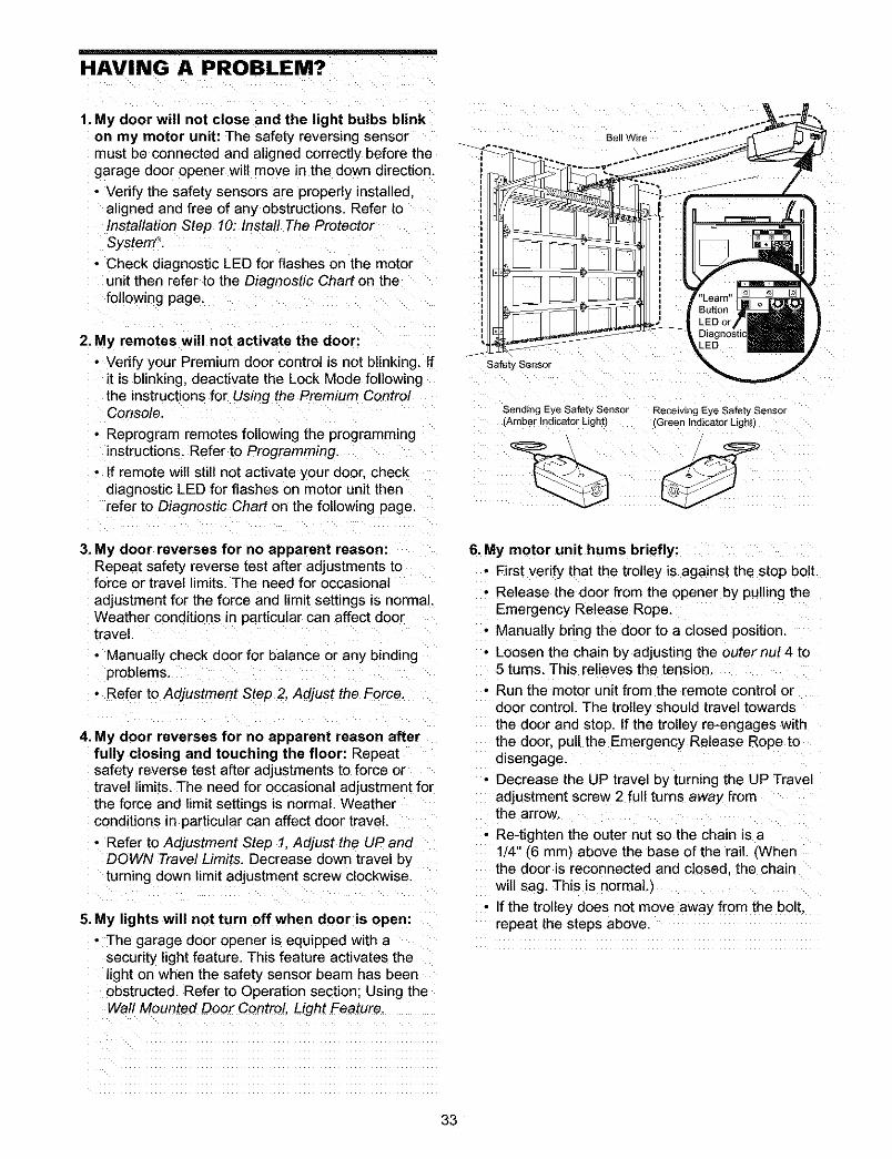
1. My door will not close and the light bulbs blinkon my motor unit: The safety reversing sensormust be connected and aligned correctly before thegarage door opener will move in the down direction.
• Verify the safety sensors are properly installedaligned and free of any obstructions. Refer toInstallation Step 10: Install The ProtectorSystem _.
• Check diagnostic LED for flashes on the motorunit then refer to the Diagnostic Chart on thefollowing page.
2. My remotes will not activate the door:
• Verify your Premium door control is not blinking. If SafetySensorit is blinking, deactivate the Lock Mode followingthe instructions for Using the Premium ControlConsole.
• Reprogram remotes following the programminginstructions. Refer to Programming.
• If remote will still not activate your door. checkdiagnostic LED for flashes on motor unit thenrefer to Diagnostic Chart on the following page.
Sending Eye Safety Sensor Receiving Eye Safety Sensor(Amber Indicator Light) (Green Indicator Light)
/
3. My door reverses for no apparent reason:Repeat safety reverse test after adjustments toforce or travel limits. The need for occasional
adjustment for the force and limit settings is normal.Weather conditions in particular can affect doortravel.
• Manually check door for balance or any bindingproblems.
• Refer to Adjustment Step 2, Adjust the Force.
4. My door reverses for no apparent reason afterfully closing and touching the floor: Repeatsafety reverse test after adjustments to force ortravel limits. The need for occasional adjustment forthe force and limit settings is normal. Weatherconditions in particular can affect door travel.
• Refer to Adjustment Step 1, Adjust the UP andDOWN Travel Limits. Decrease down travel byturning down limit adjustment screw clockwise.
5. My lights will not turn off when door is open:
• The garage door opener is equipped with asecurity light feature. This feature activates thelight on when the safety sensor beam has beenobstructed Refer to Operation section; Using theWall Mounted Door Control Light Feature
6. My motor unit hums briefly:
• First verify that the trolley is against the stop bolt.
• Release the door from the opener by pulling theEmergency Release Rope.
• Manually bring the door to a closed position.
, Loosen the chain by adjusting the outer nut 4 to5 turns. This relieves the tension.
• Run the motor unit from the remote control ordoor control. The trolley should travel towardsthe door and stop. If the trolley re-engages withthe door, pull the Emergency Release Rope todisengage.
, Decrease the UP travel by turning the UP Traveladjustment screw 2 fu!l turns away from
the arrow.• Re-tighten the outer nut so the chain is a
1/4" (6 mm) above the base of the rail. (Whenthe door is reconnected and closed, the chainwill sag. This is normal,)
• If the trolley does not move away from the bolt,repeat the steps above.
33
Bell Wire
Safe_ Sensor
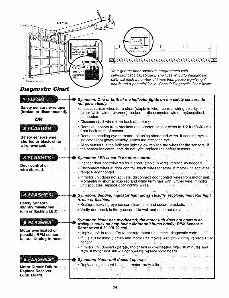
Diagnostic Chart
Your garage door opener is programmed withself-diagnostic capabilities. The "Learn" button/diagnosticLED will flash a number of times then pause signifying ithas found a potential issue. Consult Diagnostic Chart below.
Safety sensors wire open(broken or disconnected).
OR
Safety sensors w=reshorted or black/whitewire reversed
Door control orwire shorted.
Safety Sensorsslightly misaligned(dim or flashing LED).
"-0 Symptom: One or both of the Indicator lights on the safety sensors donot glow steady.• Inspect sensor wires for a short (staple in wire), correct wiring polarity
/black/white wires reversed'L broken or disconnected wires, replace/attachas needed.
• Disconnect all wires from back of motor unit
• Remove sensors from brackets and shorten sensor wires to 1-2 fl (30-60 cm;from back each of sensor.
• Reattach sending eye to motor unit using shortened wires. If sending eyeindicator light glows steadily, attach the receiving eye.
• Align sensors if the indicator lights glow replace the wires for the sensors. Ifthe sensor indicator lights do not light, replace the safety sensors
-0 Symptom: LED is not lit on door control• Inspect door control/wires for a short (staple in wire), replace as needed.
• Disconnect wires at door control, touch wires together. If motor unit activates.replace door control.
• If motor unit does not activate, disconnect door control wires from motor unit.Momentarily short across red and white terminals with jumper wire. If motorunit activates replace door control wires.
_ymptom: Sending indicator light glows steadily, receiving indicator lightis dim or flashing.• Realign receiving eye sensor, clean lens and secure brackets.
• Verify door track is firmly secured to wall and does not move.
| == Symptom: Motor has overheated; the motor unit does not operate or..............T"'w trolley is stuck on stop bolt = Motor unit hums briefly; RPM Sensor =
Motor overheated orpossible RPM sensorfailure. Unplug to reset.
Motor Circuit Failure.Replace ReceiverLogic Board.
Short travel 6-8" (15-20 cm).• Unplug unit to reset. Try to operate motor unit, check diagnostic code.• If it is still flashing 5 times and motor unit moves 6-8" (15-20 cm), replace RPM
sensor.
• If motor unit doesn't operate, motor unit is overheated. Wait 30 minutes andretry. If motor unit still wilt not operate replace logic board.
)tom: Motor unit doesn't operate.• Replace logic board because motor rarely fails.
34
PROGRAMMING
NOTICE: If this Security,l_ garage door opener is operated with a non-rolling code transmitter, the technicalmeasure in the receiver of the garage door opene_ which provides security against code-theft devices, will becircumvented. The owner of the copyright in the garage door opener does not authorize the purchaser orsupplier of the non-rolling code transmitter to circumvent that technical measure.
Your garage door opener has already been programmed at the factory to operate with your hand-held remotecontrol. The door will open and close when you press the large push button.
Below are instructions for programming your opener to operate with additional Security÷ _ remote controls.
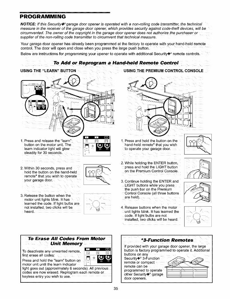
To Add or Reprogram a Hand.held Remote Control
USING THE "LEARN" BUTTON USING THE PREMIUM CONTROL CONSOLE
1. Press and release the "learn"button on the motor unit. Thelearn indicator light will glowsteadily for 30 seconds.
1. Press and hold the button on thehand-held remote* that you wishto operate your garage door.
2. Within 30 seconds press and2. While holding [he ENTER 3utton.
press and hold the LIGHT buttonon the Premium Control Console.hold the button on the hand-held
remote* that you wish to operateyour garage door. 3,
3. Release the button when themotor unit lights blink. It haslearned the code. If light bulbs arenot installed. [wo clicks will beheard
4,
Continue holding [he ENTER andLIGHT buttons while you pressthe push bar on the PremiumControl Console (all three buttonsare heldL
Release buttons when the motorunit lights blink. It has learned thecode. If light bulbs are notinstalled, two clicks will be heard.
To Erase All Codes From Motor
Unit Memory
To deactivate any unwanted remote,first erase all codes:
Press and hold the "learn" button onmotor unit until the learn indicatorlight goes out (approximately 6 seconds). All previouscodes are now erased. Reprogram each remote orkeyless entry you wish to use.
*3.Function Remotes
If provided with your garage door opener, the largebutton is factory programmed to operate it. Additionalbuttons on anySecurity÷ _ 3-Function _remote or compact _'_remote Can be _ _programmed to operate _ __other Security.l._garage ___door openers.
35
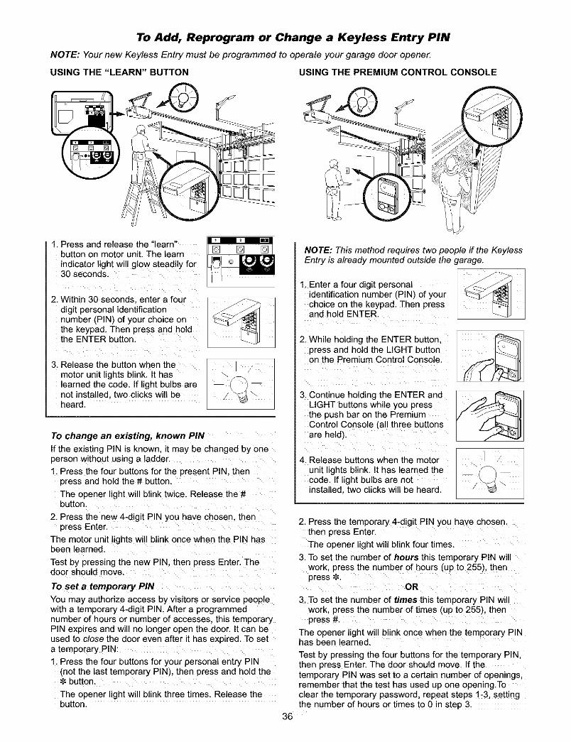
To Add, Reprogram or Change a Keyless Entry PIN
NOTE: Your new Keyless Entry must be programmed to operate your garage door opener.
USING THE "LEARN" BUTTON USING THE PREMIUM CONTROL CONSOLE
[]
1. Press and release the "learn"button on motor unit. The learnindicator lightwill glow steadily for30 seconds.
[] []
2. Within 30 seconds enter a fourdigit personal identificationnumber (PIN) of your choice onthe keypad. Then press and holdthe ENTER button.
3. Release the button when themotor unit lights blink. It haslearned the code. If light bulbs arenot installed, two clicks will beheard.
To change an existing, known PIN
if the existing PIN is known, it may be changed by oneperson without using a ladder.1. Press the four buttons for the present PIN. then
press and hold the # butter
The opener lightwill blink twice. Release the #button.
2. Press the new4-digit PIN you have chosen. Lhenpress Enter.
The motor unitlightswill blink once when the PIN has_eenlearned.
Test by pressing the new PIN. then press Enter. Thedoor should move.
To set a temporary PIN
You may authorize access by visitors or service peoplewith a temporary 4-digit PIN. After a programmedqumber of hours or number of accesses, this temporaryPIN expires and will no longer open the door. It can beused to close the door even after it has expired. To seta temporary PIN:1. Press the four buttons for your personal entry PIN
(nat the last temporary PIN), then press and hold thebutter
The opener lightwill blink three times. Release thebutton.
NOTE: This method requires two people if the KeylessEntry is already mounted outside the garage.
1. Enter a four digit personalidentification number (PIN) of yourchoice on the keypad. Then pressand hold ENTER.
2. While holding the ENTER button,press and hold the LIGHT buttonon the Premium Control Console.
3. Continue holding the ENTER andLIGHT buttons while you pressthe push bar on the Premium
Control Console (all three buttonsare held).
4, Release buttons when the motorunit lights blink. It has learned the
code. If light bulbs are netinstalled, two clicks will be heard.
2. Press the temporary 4-digit PIN you have chosen,then press Enter.The opener light will blink four times.
3. To set the number of hours this temporary PIN willwork, press the number of hours (up to 255), thenpress _.
OR
3, To set the number of times this temporary PIN willwork, press the number of times (up to 255), thenpress #.
The opener lightwill blink once when the temporary PINhas been Jearned.
Test by pressing the four buttons for the temporary PIN,then press Enter. The door should move. If thetemporary PIN was set to a certain number of openings,remember that the test has used up one opening.Toclear the temporary password, repeat steps 1-3, settingthe number of hours or times to 0 in step 3,
36
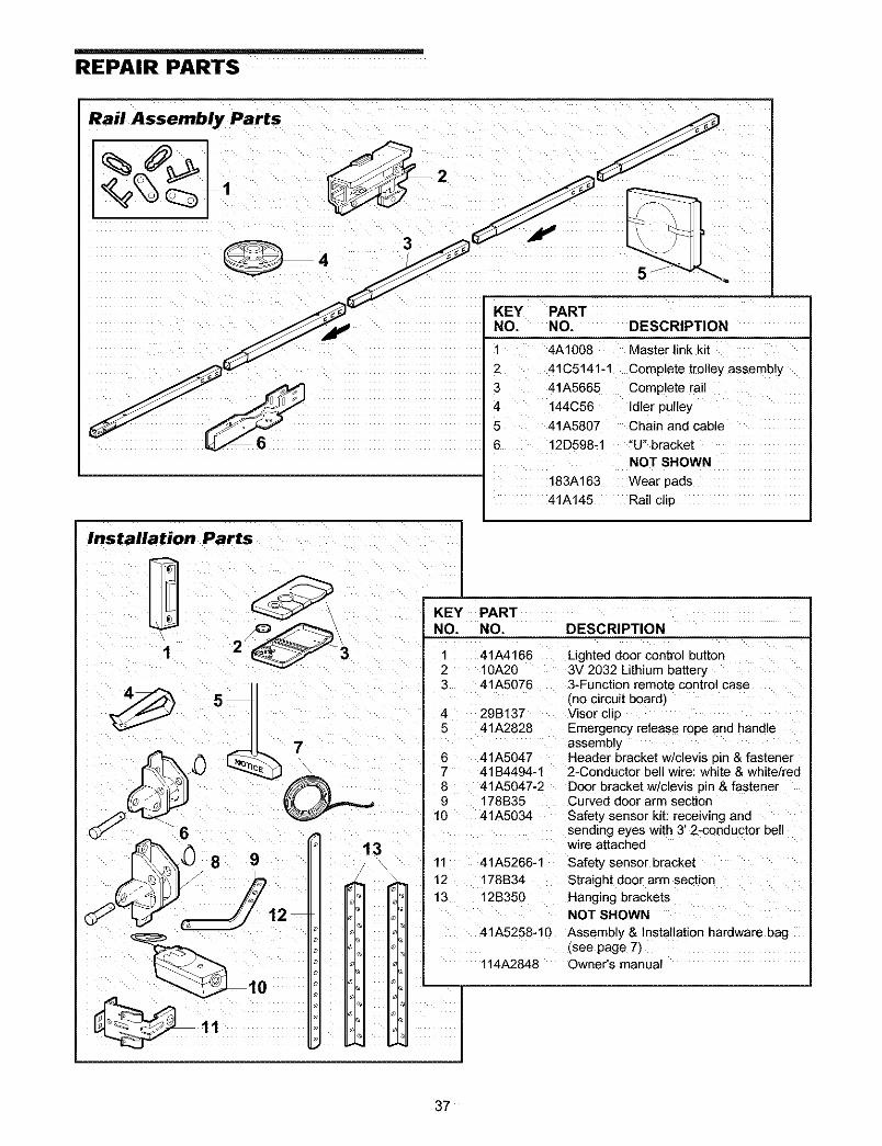
REPAIR PARTS
Rail Assembly Parts
5 .
KEY PARTNO. NO. DESCRIPTION
1 4A1008 Master link kit
2 41C5141-1 Complete trolie
3 41A5665 Complete rail4 144C56 Idler pulley
5 41A5807 Chain and cable
6 12D598-1 "U" bracketNOT SHOWN
183A163 Wear pads
41A145 Rail clip
Installation Parts
I 2
KEY PARTNO. NO. DESCRIPTION
1 41A41662 10A203 41A5076
4 29B1375 41A2828
6 41A50477 41B4494-18 41A5047-29 178B35
10 41A5034
Lighted door control button3V 2032 Lithium battery3-Function remote control case(no circuit board_Visor clipEmergency release rope and handleassemblyHeader bracket w/clevis pin & fastener2-Conductor bell wire: white & white/redDoor bracket w/clevis pin & fastenerCurved door arm section
Safety sensor kit: receiwng andsending eyes with 3' 2-conductor bellwire attached
11 41A5266-1 Safety sensor bracket
12 178B34 Straight door arm section
13 12B350 Hanging bracketsNOT SHOWN
41A5258-10 Assembly & Installation hardware bag(see page 7_
114A2848 Owner s manual
137
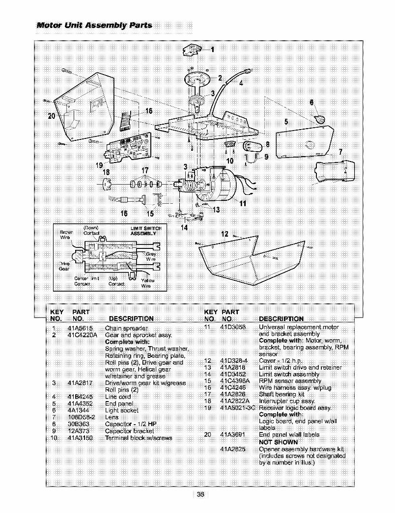
MotorUnitAs_mblyPa_s
iiiiiiiiiiiiiiiiiiiiiiiiiiiiiiiiiiiiiiiiiiiiiiiiiiiiiiiiiiiiiiiiiiiiiiiiiiiiiiiiiiiiiiiiiiiiiiiiiiiiiiiiiiiiiiiiN_T8H_Niiiiiiiiiiiiiiiiiiiiiiiiiiiiii
iiiiiiiiiiiiiiiiiiiiiiiiiiiiiiiiiiiiiiiiiiiiiiiiiiiiiiiiiiiiiiiiiiiiiiiiiiiiiiiiiiiiiiiiiiiiiiiiiiiiiiiiiiiiiiiiiiiiiiiiiiiiiiiiiiiiiiiiiiiiiiiiiiiiiiiiiiiiiiiiiii
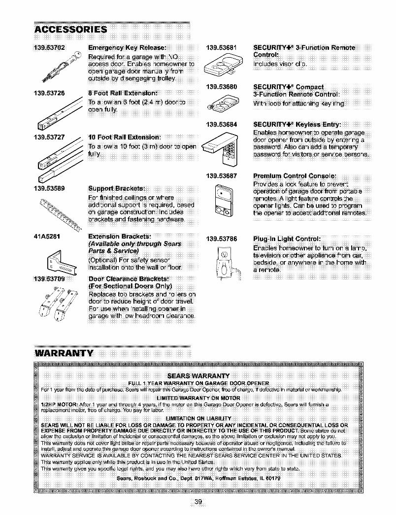
ACCESSORIES___________________________________________________________________________________
139i53702
139.53726
EmergenCY KeY Re!_a_i 139.53681 SECURi_4,_ _Fd n_io, Remo_e
........................................................... 139.53680 SECURI_4,_ Compact
139.53727
139.53684SEaCbURIT_or_K:y/e_so_ert_at:eg_rageii .....
139.53687
139.53589 SUFpo_ B_cketSi
41A5281 ExtemsiOn Bracketsi 139.53786{Avaitable on_ _Ugh Sea_
139i53709 DO_ Glea_an_ Bra_ke_ i
dO0_:_0redu_ I_e!gh_O_dO0__:ravel:
P emlum Control Gonsole
iiiiiiiiiiiiiiiiiiiiiiiiiiiiiiiiiiiiiiiiiiiiiiiiiiiiiiiiiiiiiii
WA R RJ_
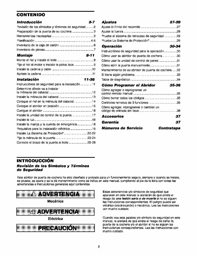
CONTENIDO
Introducci6n 2-7
Revisi6n de lossfmbolos y t6rminos de seguridad .........2
Preparaci6n de la puerta de su cochera ......................... 3Herramientas necesarias ................................................. 3
Planificaci6n ................................................................. 4-5
Inventario de la caja de cart6n ........................................ 6
Inventario de piezas......................................................... 7
Montaje 8-11
Monte el riel y instale el trole ........................................... 8
Fije el riel al motor e instale la polea Ioca ....................... 9
Instale la cadena y cable .............................................. 10
Apriete la cadena ........................................................... 1.1
Instalaci6n 11.26
Instrucoi6nes de seguridad para letinstalaci6n .............. .11Determine dSnde va a instalarla m6nsula del cabezal .................................................. .12
Instale la m6nsula del cabezal ...................................... .13
Coloque el riel en la m6nsula del cabezal ..................... .14
Coloque el abridor en posici6n ...................................... .15
Cuelgue el abridor ......................................................... .16
Instale la unidad de control de la puerta ....................... .17Instale la luz ................................................................... 18
Instale la manija y la cuerda de emergencia ................. .18
F_equisitospara la instalaci6n el6ctrica ......................... .19Instale La Sistema de Protecoi6n_ ........................... 20-22
Fije la m6nsula de la puerta ..................................... 23-24
Conecte el braze de la puerta al trole ...................... 25-26
Ajustes 27-29
Aju_e el Ifmite del recorrido.......................................... 27
Aju_e la fuerza .............................................................. 28
F_ruebeel sistema de retroceso de seguridad ............... 29F_ruebeLa Sistema de ProtecciSn_................................ 29
Operaci6n 30-34
Instrucci6nesde seguridad para la operaci6n ............... 30
C6mo usar su abridor de puerta de cochera ................. 30
C6mo usar la unidad de control de pared ..................... 3"i
C6mo abrir la puerta manualmente ............................... 3.1
Mantenimiento de su abridor de puerta de cochera.,..,.32
Si tiene alg=3nproblema ................................................. 33
Tabla de diagn6stico ...................................................... 34
C6mo Programar el Abridor 35-36
C6mo agregar o reprogramar uncontrol remote manual ................................................... 35
C6mo borrar redes los cSdigos ...................................... 35Controles remotos de 3 funciones ................................. 35
C6mo agregar, reprogramar o cambiar uncSdigo de entrada sin Ilave............................................ 36
Accesorios 37
Garantia 37
N_meros de Servicio Contratapa
INTRODUCCION
Revisi6n de los Simbolos y T_rminosde Seguridad
Este abridor de puerta de cochera ha side disefiado y probado para un funcionamiento seguro, siempre y coando se instale,se pruebe, se opere y se le d_ mantenimiento come se indica en este manual, cumpliendo al pie de la letra con todas lasadvertencias e instrucoiones generales aqufcontenidas.
Mecdnica
Eldctrica
Estas advertencias y/e stmboles de seguridad queaparecen en este manual le alertar_.nde que existe elriesgo de una lesl6n serla o de muerte si nose siguenlas instrucoionescorrespondientes. El peligropuedeserel_ctrico (electrocucibn)o mec_.nico.Lea las instrucoionescon muchocuidado.
Cuando yea esta palabra y/o stmbolo de seguridad en estemanual, le alertar_,de que existe el riesgo de dafiar lapuerta de la cochera y/o el abridor si no se siguen lasinstrucoionescorrespondientes. Lea las instrucoionescontouche cuidado.
2
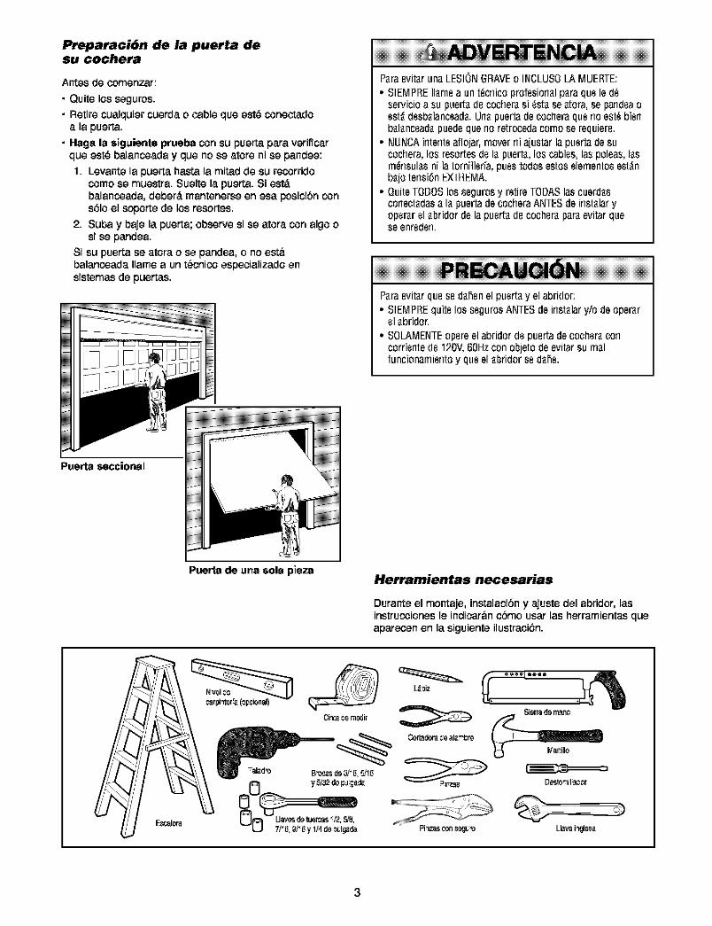
Preparaci6n de !,,1puerta desu cochera
Antes de comenzar:
• Quite los seguros.• Retire cualquier cuerda o cableque est_ conectado
a la puerta.• Haga la $iguiente prueba consu puerta para verificar
que est_ balancoada y que no se atore ni se pandee:
1. Levante la puerta basra la mitad de su recorridocome se muestra. Suelte la puerta. Si est,.balancoada, deber_, mantenerse en esa posicibn cons61oel soporte de los resortes.
2. Suba y baje la puerta;observe si se atora con algoosi se pandea.
Si su puertase atora o se pandea,o no estabalancoada Ilamea unt_cnicoespecializado ensistemasde puertas.
Puerta $ecoional
Paraevit_runaLESIONGRAVEo INCLUSOLAMUERTE:
• SIEMPREIlamea un t_cnicoprofesionalparaquele(1_servicioa supuertadecocher_si _stase_tora,se pan(leaoest_(lesbalanceada.Urlapuertadecocheraquerioest_bier1balanceadapuedequeno retrocedacomose requiere.
• NUNCAintenteaflojar,movernia[ustarla puertadesucochera,los resortesdela puem, los cables,las poleas,lasm_nsulasni la tornillerfa,puestodosestoselementosest_nba[oterlsi_nEXTREMA.
• QuiteTODOSlos segurosy retireTODASlas cuerdasconeciadasa la puertadecocheraANTESdeinstalaryoperarelabridordela puertade cocheraparaevitarqueseenreden.
Paraevit_rquesedahenel puertayel abridor:° SIEMPREquitelos segurosANTESdeinstalaryiodeoperar
el abridor.= SOLAMEN_Eopereelabridordepuertadecocheracon
corrientede 120V,60Hzcon ob[etodeevitarsu realfuncionamierltoy queel abridorse dahe.
PuePm de una sole piezaHerramientas necesarias
Durante el montaje, instalacibn y ajuste del abridor, lasinstrucoiones le indicar&n ¢bmo usar las herramientas queaparecen en la siguiente ilustraci6n.
E_iz
C._r_dora_o_.-br_
Sierrado m_n¢
3
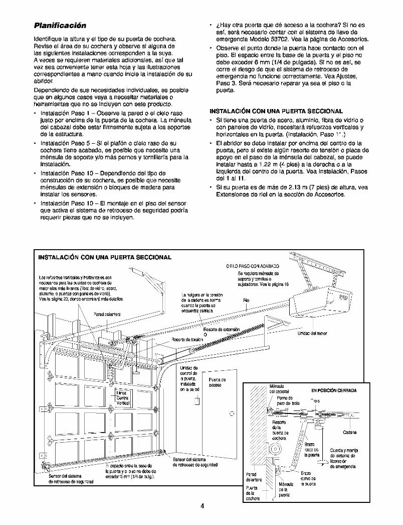
Planificaci6n
Identifiquela altura y el ripe de su puerta de coohera.Revise el _.reade su oechera y observe si alguna delas siguientes instalaoiones corresponden a la suya.A vecos se requieren materiales adicionales, asf que talvez sea conveniente tenor esta hoja y los ilustracienesoerrespendientes a mane coando inicie la instalacibnde suabridor.
Dependiendo de sus necesidades individuales,es posiblequeen algunoscasesvaya a necositar materiales oherramientas que nose incluyen coneste producto.
• InstalacibnPaso 1 - Obsewe la paredo el oielo rasojustoper encima de la puertade la coohera. La m_nsuladel cabezal debe estar firmemente sujetaa lossoportesde la estructura.
• InstalacibnPaso 5 - Si el plafSno cielo rose de sucoohera tiene aoabado, es posible que necosite unam_nsula de soporte y/o m_.spernos y tornillerfa para lainstalaoi6n.
• InstalacibnPaso 10 - Dependiendodel ripe deconstrucoi6n de su oochera, es posible que necositem_nsulas de extensi6n o blcques de madera parainstalar los sensores.
• InstalacibnPaso 10 - El montaje en el piso del sensorque activa el sistema de retrocoso de seguridad podrfarequerir piezas que no se incluyen.
i,Hay otra puerto que d_ accoso a la cochera? Si no esasf, set&necosario contar con el sistema de Ilave deemergencia Modelo 53702. Yea la p_gina de Acoesorios.Obsewe el punto donde la puerto haco contacto con elpiso. El espaoio entre la base de la puerto y el piso nodebe excoder 6 mm (1/4 de pulgada). Si no es asf, secorre el riesgo de que el sistema de retrocoso deemergencia no funoione correotamente. Vea Ajustes,Paso 3. Ser&neoesario reparar ya sea el piso o lapuerta.
INSTALACI(_N CON UNA PUERTA SECCIONAL
Si tiene una puerto de acoro, aluminio, libra de vidrio ocon paneles de vidrio, necositar_, re1_uerzosverticales yhorizontales en la puerta. (Instalaoi6n, Paso 11.)
El abridor se debe instalar per enoima del centre de lapuerta, pore si existe algOn resorte de tensibn o plaoa deapoyo en el paso de la m_nsula del cabezal, se puedeinstalar hasta a 1.22 rn (4 pies) a la derecha o a laizquierda del centre de la puerto. Yea Instalaoi6n, Posesdel 1 a111.
• Si su puerta es de m&s de 2.13 m (7 pies) de altura, yeaExtensiones de riel en la secoi6n de Acoesorios.
INSTALACI(_N CON UNA PUERTA SECCIONAL
Uride_ del rno_or
©
4
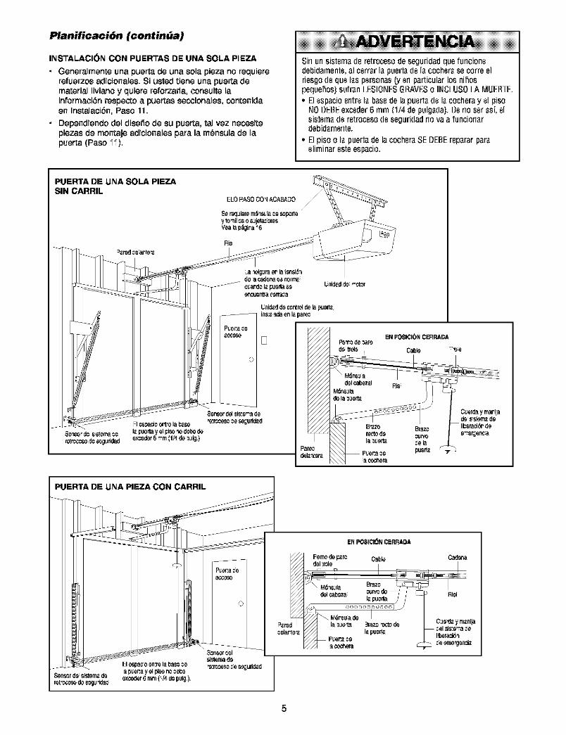
Planificaci6n (continUa)
INSTALACI6N CON PUERTAS DE UNA SOLA PIEZA
• Generalmenteuna puertade una sola pJezano requJere
refuerzosadicionales.Si usted tiene unapuertademateriallivianoy quierereforzarla,oonsulte lainformaoi6nrespectoa puertassecoionales,contenidaen Instalacibn,Paso 11.
• Dependiendodel disefiode su puerta,tal vez necesitepiezas de montaje adicionalespara la m_nsula de lapuerta(Paso 11).
Sinurlsistemaderetrocesodeseguridadquefurlcionedebidamente,al cerrarlapuem delacocherasecorreelriesgodequelas pen_onas(y erlparticularlos nihospequehos)sultan LESIONESGRAVESo INCLUSOLA MUER_E.• Elespacioentrela basedelapuertadelacocheray el piso
NODEBEexceder6 turn (1/4depulgada).Benoser ast,elsistemade retrocesodeseguridadriovaa funcionardebidarnente.
= Elpiso o lapuertadela cocheraSEDEBErepararparaelirninaresteespacio.
PUERTA DE UNA SOLA PIEZASIN CARRIL
PUERTA DE UNA PIEZA CON CARRIL
Oadena
Rill
5
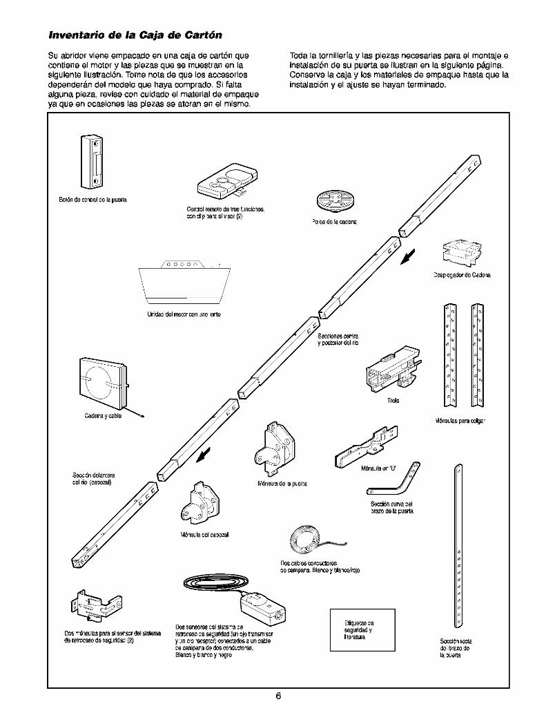
Inventario de la Caja de Cart6n
Su abridor viena ampacado an unacaja de cartbnquacontiene el motor y las plazas qua sa muastran an lasiguianta ilustraci6n. Tome norade qua los accasoriosdependarbn del modelo qua haya comprado. Si faltaalguna plaza, revise con cuidado el material de ampaqueya qua an ocasioneslas plazas se atoran an al mismo.
Toda la tornillarfay las plazas nacesarias para el montaje ainstalacibn de su puerta se ilustranan la siguiantap_gina.Conserve la caja y los matarialas de empaqua basra qua lainstalacibn y el ajusta sa hayan tarminado.
6
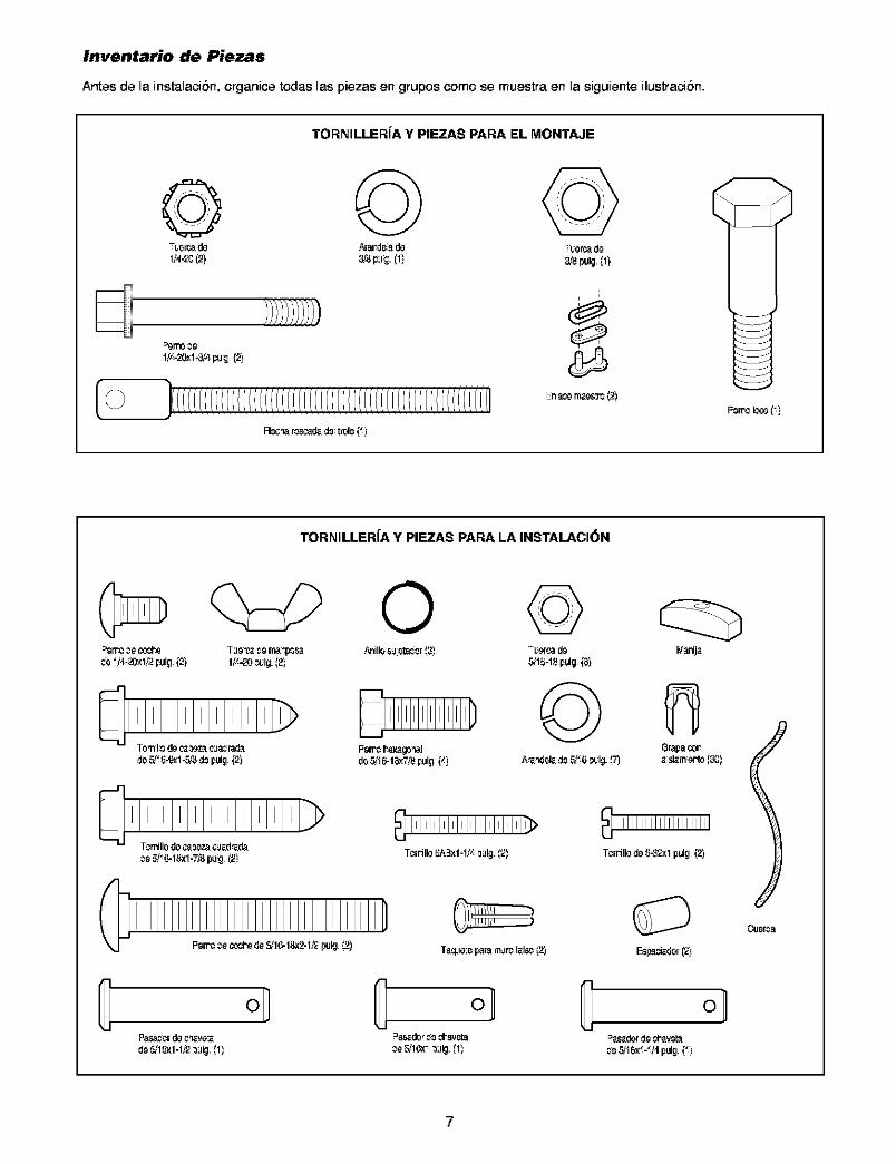
Inventario de Piezas
Antes de la instalacibn, organice todas las piezas en grupos¢omo se muestra en la siguiente ilustracibn.
TORNILLERfA Y PIEZAS PARA EL MONTAJE
© © ©
1/x.L_<l-_d pu,_ (2]
R_c_ar_scad_d_trol_(_]
TORNILLERfA Y PIEZAS PARA LA INSTALACI_N
O_o _/,I120-xl12pulg (2) 1/x.20 _ulg. _2)
do5/_54_1 -_'8 d_pulg (2) do_16-18_ pulg (_)
Taq_le:_papam_lmf_.ls¢(2}
©_l;Gr_ do
©_anija
Grapaco_
TcrrJllodo5.-'J_ 1pulg(2)
Esp_dor(_)
oldo_'1_1-1_2 _ iIg._1_ _ _16x_ _ iIg._1_ _ _16x_-_/4 pulg (_)
7
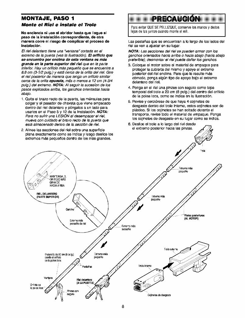
MONTAJE, PASO 1Monte el Riel e instale el Trole
No encienda ni use el abridor haste que Ilegue elpaso de la instalaci6n cor_spondiente, de otramanera corre el rieago de complicar el proceso deinetalaci6n,
El riel delantero tiene una "ventana" ¢ortada en et
extreme de ta puerta {yea ta ilustreciSn). E! otlf!¢!o quese eneuentra pot enelma de esta ventana es m_,$grande en la parte super!or del tie! queen ta parteinferio_ Hay un orificio m_s peque_o que se encuentre a8.9 cm (3-1/2 putg.) y est_ osrea de la orilta del rieL Gireel riel posterior de manera clue tenga un orificio similarosrca de ta oritla opuesta, m_s o menos a 12 cm (4-3/4pulg.) del extreme. NOTA: AI seguir la suces[on de lospesos explicados arriba, los ganchos orientados haciaabajo.
I. Quite el braze recto de la puerta, las m_nsulas paracolgar y el pasador de ohaveta que viene empaoadodentro del riel delantero y p6ngalos a un lade pareusarlos en el Paso 5 y 12 de la Instalaoi6n. NOTA:Pare no sufrir una LESI6N at desempacar el riel,mueva con cuidedo et brezo recto de ta pueria Clueest_ almacenado dentro de ta secoiSn de rieL
2. Alinee las secoiones del riel sobre una superficieplane exactamente come se indicay luego deslioe losextremes mds pequeffos dentro de los m&s grandes.
Par_evitarQUESEPELLIZQUE,conservelos manosy de(loslejos(le I_s[urlt_ScuarldOmonteel reil.
Las pesta5as que se encuentran a Io largode los lades delriel se van a ajustar en su lugar.
NOTA: Lee secoionesdel riel se pueden armar con losganchos orientados hacia amba o hacia abajo (hacia abajopreferibte); desmontar et riet puede der}ar los ganchos.3. Coleque el motor sebre el material de empaque para
proteger la cubierta del mismo y apeye el extremeposterior del riel encima. Pare que le resulte m_.so6modo, penga alg0n tipe de apeyo baje el extremedelantero del riel.
4. Pongaen el riel una pinzas consegurocome topetemporal del trole a 20 om (8 pulg.) del centre del ofifioiode la pelea leca, come se indioa en la ilustraci6n.
5. Revise y oerci6rese de que haya 4 cojinetes dedesgaste dentro del trele interne, estos cojinetes sen depl&stico. Si los cojinetes se hen soltadodurante eltransperte, revise rode el material de empaque. Pongalos cojinetes de desgaste en su lugar come se indica.
6. Deslico el trole a Io largo del riel desdeel extreme posterior hacia las pinzas.
8
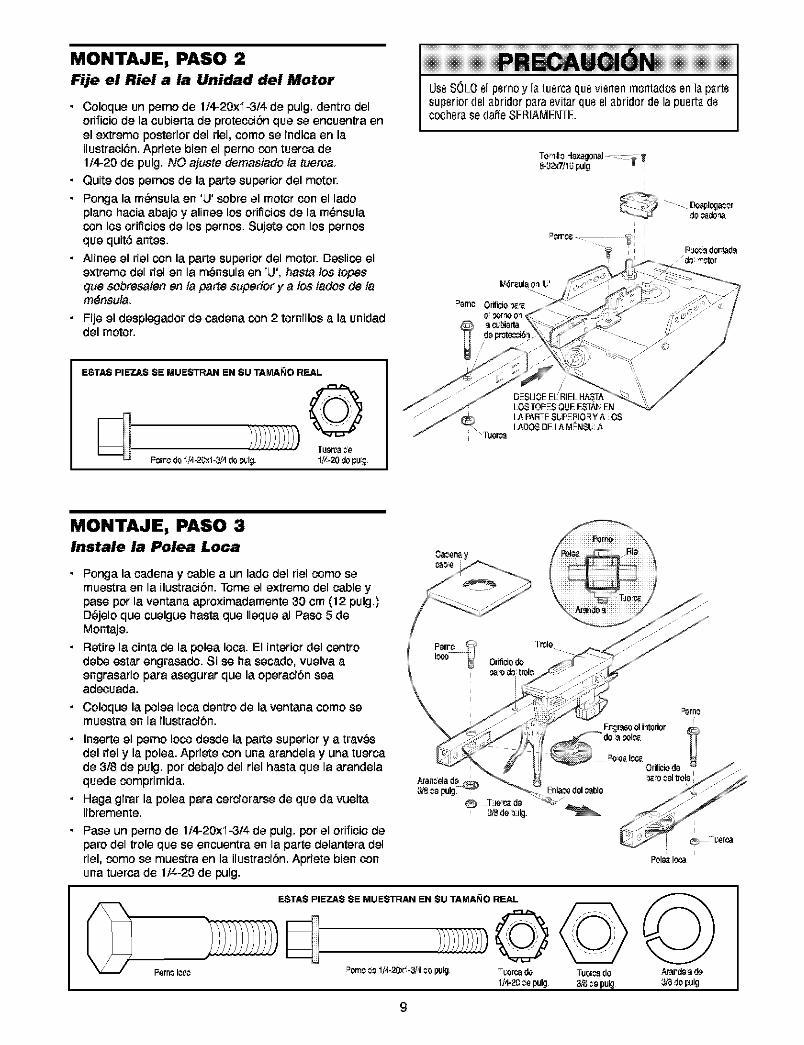
MONTAJE, PASO 2
Fije el Riel a la Unidad del Motor
• Coloque un perno de 1/4-20xi-3/4 de pulg. dentro delorificio de la cubierta de proteccibn que se encuentra enel extremo posterior del riel, como se indica en lailustraci6n. Apdete bien el perno con tuerca de1,4-20 de pulg. NO ajuste demasiado ia tueroa.
• Quite dos pernos de la parte superior del motor.
• Ponga la m_nsula en %!' sobre el motor con el ladopiano hacia abajo y alinee los orificios de la m_nsulacon los orificios de los pernos. Sujete con los pernosque quit6 antes.
• Alinee el riel con la parte superior del motor. Deslico elextremo del riel en la m_nsula eft 'L!', hasta los topesclue sobresaien en ta parte superior y a los tados de tam6nsuia.
• Fije el desplegador de cadena con 2 tornillos a la unidaddel motor.
ESTAS PIEZAS SE MUESTRAN EN SU TAMANO REAL
//li/i/i//),°o °o0P_rr¢ de _J4-2_1-_4 de _lg. 1/x.20 dopu;.
do_do_a
MONTAJE, PASO 3Instale la Polea Loca
• Ponga la cadena y cable a un lado del riel como semuestra en la ilustracibn. Tome el extremo del cable ypase por la ventana aproximadamente 30 cm (12 pulg.)D_jelo que cuelgue basra que Ileque al Paso 5 deMontaje.
• Retire la cinta de la polea Iota. El interior del centrodebe estar engrasado. Si se ha Secado, vuelva aengrasarlo para asegurar que la operaciSn seaad_cuada.
• Coloque la polea Iooa dentro de la ventana como semuestra en la ilustraci6n.
• Inserte el perno Ioco desde la parte superior y a trav_sdel riel y la polea. Apriete con una arandela y una tuercade 3/8 de pulg. por debajo del riel basra que la arandelaquede comprimida.
• Haga girar la polea para cerciorarse de que da vueltalibremente.
• Pase un perno de 1f4-20x'i-3/4 de pulg. por el orificio deparo del trole que se encuentra en la parte delantera delriel, como se muestra en la ilustraciSn. Apriete bien conuna tuerca de 1f4-20 de pulg.
Fern_lcc¢
ESTA$ PIEZA$ SE MUESTRAN EN SU TAMANO REAL
9
POI_ I_,a
,_ard__ de3/_dopulg
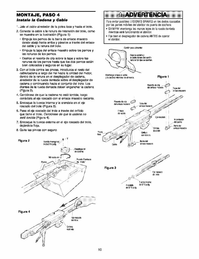
MONTAJE, PASO 4Instale la Cadena y Cable
I. Ja.le el ca.ble a.lrededor de la. polea. Ioca. y ha.cia,el trole.
2. Conecte la. cable a. la. ra.nura,de retenci6n del trole, comese muestra, en la. ilustra.ci6n (Figura. 1):
• Empuje los pernos de la. ba.rra,de enla.co maestrodesde a.ba.joha.cia, a.rriba,y p&selos a. tra.v_s del enla.cedel cable y la.ra.nura, del trole.
• Empuje la.ta.pa,del enla.ce maestro sobre los pernos yla.s ra.nura.sde los pemos.
• Deslico el resorte de clip sobre la. ta.pa,y sobre la.sra.nura.s de los pernos ha.sta,que los dos pernos est_nbien coloca.dos y seguros en su luga.r.
3. Con el trole contra, la.s pinza.s, introduzca, el resto delca.ble/ca.dena, a. largo del riel ha.cia, la.unida.d del motor,dentro de la. ra.nura,en el desplega.dor de ca.dena.,a.lrededor de la.rueda, denta.da, sobre el desplega.dor deca.dena, y continua.ndo ha.cia,el conjunto del trole. Losdientes de la. rueda, dentada, deben enga.ncha.r la.ca.dena.(Figura 2).
4. Cercibrese de que la.cadena no est_ torcida, luegocon_.,ctela,a.I eje rosca.do con el enla.co maestro resta.nte.
5. Enrosque la.tuerca, interna, y la. a.ra.ndela,en el ejerosca.do del trole (Figura. 3).
6. Pa.se el eje rosca.do del trole a. tra.v_s del orificioque tiene el trole. Cercidrese de clue/a ca.dena, noest6 torcida (Figura. 4).
7. Enrosque la.tuerca, externa, en el eje rosca.do del trole,dej&ndola, floja..
8. Quite la.s pinzas con seguro.
Figure 2 T_milloI-ex_l _-
!iii!iii!iii!iii!iii!iii!iii!iii!iii!iii!iii!iii!iii!iii iii!iiA TEIA!!!!!!!!!!!!!!!!!!!!!!!!!!!!!!!!!!!!!!!!!!!!!!!!!!!!!!!!!!!!!!!P_raevit_rposiblesLESIONESGRAVESerl los (ledosc_usad_spor I_spartesm6vilesdel_bridor(le puertadecochera:• SIEMPREmanteng_las m_noslejosdeI_ ruedadentad_
mientrasest_funcionandoelabridor.
• Filebienel despleg_dordec_denaAN_ESdeoper_rel _bridor.
C_.rt6rpar_a imont_r
Dojela_der_ yol cablod_'itsodel_E_
W9_ten,;._:o'isos o ¢_.bl0y la m_r_ mimosas_ _1m_m_. Figura 1
R6scrt_d_ _pdel erl_.ce_a_'tro ; T_.padel
Figure 3
Figure 4
r_dc_Jo
lO
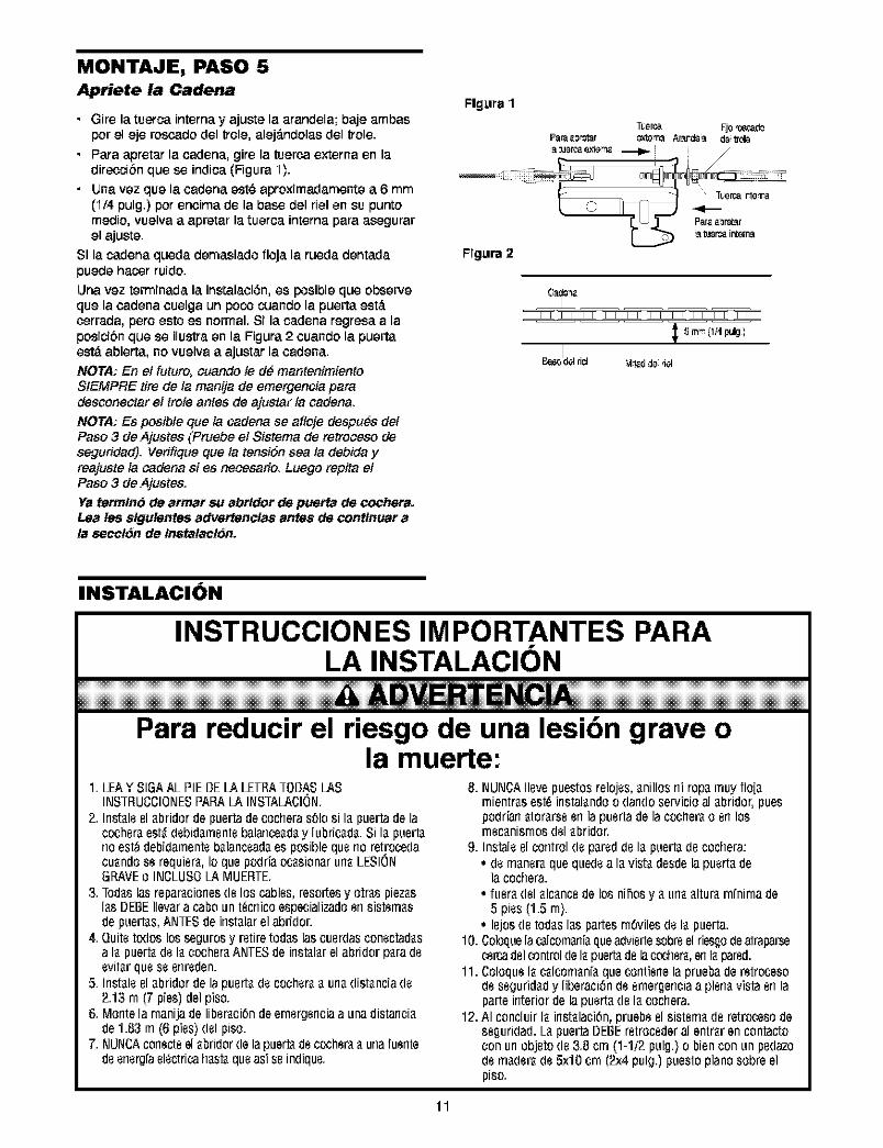
MONTAJE, PASO 5
Apriete la Cadena
• Gire la tuerca interna y ajuste la arandela; baje ambasper el eje rescade del trole, alej_.ndelas del trele.
• Para apretar la cadena, gire la tuerca externa en ladireccibn que ea indica (Figura I ).
• tJna vez que la ¢adena est_ aproximadamente a 6 mm(I/4 pulg.) per encima de la base del riel en su puntomealie, vuelva a apretar la tuerca interna para aeagurarel ajuste.
Si la cadena queda demasiado floja la rueda dentadapuede hacer ruido.
Llna vez terminada la instalaci6n, es posible que observeque la cadena cuelga un poco cuando la puerta est,.terraria, pete esto es normal. Si la cadena regresa a laposicibn que ea ilustra en la Figura 2 cuando la puertaest,. abierta, no vuelva a ajustar la ¢adena.
NOTA: En el future: cuando te d_ mantenimientoSIEMPRE tire de la manija de emergencia paradeseanectar el trote antes de ajustar ta cadena.
NOTA: Es peaibte que la cadena ea afloje despu_s de/Paso 3 de Ajustea (Pruebe el Sistema de retroceao deeagurided). Verifique clue ta tensiSn sea la debida yreajuste la cadena si es neoeaado. Luego repita elPaso 3 de Ajustea.
Ye terrain6 de ermer su ebrldor de puerta de cochera.Lee lea $!gulentes edvettencle$ antes de continuer ete eacc!6n de Instatec!6n.
Flgura 1
Flgura 2
ii
0_o_ i
, _3m_ (1/4 pulg_iI
Bas_del rill _d do del
INSTALACION
INSTRUCCION ES IMPORTANTES PARALA INSTALAClON
ERTEN¢!Para reducir el riesgo de una lesibn grave o
la muerte:1. LEAYSIGAALPIEBELALETRATOBAS/AS
INSTRUCCIONESPAPALA INSTA/ACION.2. Irlst_leel_bridordepuertadecocheras61osi I_ puertadela
cocher_est_debid_mentepalance_d_y lubric_d_.Si I_ puert_rioest_debidamenteb_lancead_es posiblequerioretrocedacu_ndose requier_,Io quepodriaoc_sionarurl_LESIONGRAVEo INCLUSO/AMUERTE.
3.Ted,s las repar_ciorles(le los cables,resortesy orris piez_sI_sDEBEIlevara caDoun t_crlicoespacializadoerlsistem_sdepuert_s,ANTESdeinst_larelabridor.
4. Quitetodoslos segurosy retiretodaslascoerdasconectad_sa la puert_dela cocheraANTESde ir_st_larelabridorparadeevit_rquese erlreden.
5. Irlst_leel_bridordelapuert_decocher__ url_dist_nciade2.13rn (7 pies)delpiso.
6. Montelarnanijadeliber_ci6ndeernergerlciaa unadistarlci_de1.83m (6pies)delpiso.
7. NUNCAcorlecteel_Dridordeiapue_ decocher'__ urlafuerltedeer_erg[ael_ctricahast_queasTseindique.
8. NUNCAIlevepuestosrelojes,_nillosr_irop_muyflo[_rnientr_sest_irlstal_ndoo darldOservicioal _bridor,puespodrTarl_tor_rseerl lapuertadela cooher-&o erl losmec_nismosdel_bridor.
9. Instaleelcontroldep_reddeI_ puert_decochera:• (Iem_ner'_quequedea I_vist_desdelapuert_de
lacochera.• fuer_del_lc_ncede los nihosy _url__ltur'_rn[nirnade
5 pies(1.5 rn).• lejosde ted,s I_spartesrn6vilesdeI_puerta.
10. Coloquela(_lcom_rfi_queadviertesobr_el riesgodeatraparsecercadelcontroldeI_puert_delaccoher_,enI_pared.
11. ColoqueI_ c_lcom_n[_quecorltierlela pruepaderetrocesodesegurid_dy liberaci6nde ernergerlciaa plerl_vistaerl laparteinteriordela puert_deI_Cochera.
12.AIconcluirI_ inst_laci6n,pruebeel sistem_deretrocesodeseguridad.L_puertaDEBEretrocederal entr_rencontactoconur_objeto(le3.8 cm (1-1/2pulg.)o bienconun pedazo(lem_(ler'_(le5x10crn (2x4pulg.)puestopianosobreelpiso.
11
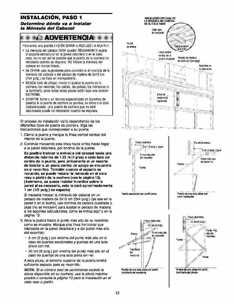
INSTALACION, PASO 1Determine d6nde va a instalarla M6nsula del Cabezal
Pareevf[arunaposibleLESIONGRAVEo INCLUSO/AMUERTE:• La m_nsuladelcabezalBEBEquedarRiGIDAMENTEsu[eta
al soporteestrucLuralerl lapareddelanterao erlel cieloraso,(lerioserosi esposiblequelapuertadelacocherorioretrocedecuorldOserequiera.NOirlstalelarn_rlsula(lelcabezalen inuresraises.
• SeBEBENusarsu[etadorespareconcretesi el montajedelarn_nsuladelcabezalo delpedazode rnaderade5x10cm(2x4 pulg.)sehaceen mamposteda.
• NUNCAIratedeaflojar,moverniojustarlapuertadelacochero,los resortes,los cables,lospoleas,las rn_nsulasnila torniller[a,puesto(losestospiezosest_nbojounatensiGnEXTREMA.
• SIEMPREflamea unt_crlicoespeciolizodoensistemasdepuertassi lapuertadecocherase pan(lea,seatorao si est_desbalonceoda.Unapuertodecocheroquenoest_balanceadapuedenoretrocedercuandose requiera.
El procoso de instalaci_;nvarfa dependiendo de losdiferentes tipos de puerta de cochera. Siga lasinstrucoiones que correspondan a su puerta.
I. Cierre la puerta y marque la Ifnea central vertical delinterior de la puerta.
2. ContinUe marcando esta l/nea hacia arriba haste Ilegara la pared delantera, per encima de la puerta.
Ee peelble Inetalar la m_neula del cabe_al haste unadlstancla rm_xlrna de 1.22 rn (4 plee) a cede lade delcerttro de la puerta, pero _nlcamente el un reeortede toral6n o un place central de apoyo se encuentraen el racorrldo, Tarnbl6n cuando el e_paclo eereducldo, ee puede lnstalar la rneneula en el clelorace o plafGn de la cochera {yea la p6glna 13).{Aelmlemo, se puede lnstalar Invertlda sabre lapared el ee necesarlo, esto le dar6 aproxlmadarnente1 cm (1/2 pulg,) de eepaclo),
Si ngcesita instalar la m_nsula del cabezal en un
pedazo de madera de 5xI0 cm (2x4 pulg.) (ya sea en lapared o en el techo), use tornillos de cabeza cuedreda opijas (no se incluyen) pare sujetar el pedazo de maderaa los soportes estrueturales, come se indica aquf yen lap&gina I3.
3. Abra la puerta haste el punto m&s alto de su recorridocome se muestra. Marque una l/nea horizontal queintersecte en la pared delantera y a del punto m_.s altodel recorrido:
• 5 cm (2 pulg.) per encima del punto m&salto en elcase de puertas secoionales y puertas de una solepieza con riel.
• 20 cm (8 pulg.) per encima del punto m&salto en elcase de puertas de una sola pieza sin riel.
A esta altura, el extreme superior de la puerta tendr&suficiente espacio pare su recorrido.NOTA: Si et nSmero total de osnt[metros exc'ede laaltura disponibte en su cochera, use ta attura m_:imaposible o ¢onsulte la p_gina 13 pare la tnstataciGnen etcielo raso o plafGn.
INSTALACI_N OPCIONALDELA MENeULA DEL CABEZAL.
dead.tara
ii 5¢_(2pug)Oarril
f! ;/
d_r_conido
:ii i_ _u_r_
Puertt__clonal ¢o_ Ct_l'llc_rvo
j ;; Funt__s _1:o
Puertade unasole _ co_cawll h_lzontal
Pt_rt_ d_ un_LS_a p]ezasfn_rrll:tom]llerfa d_4m_te
Pue_a de una ple,,.asrn_r rll:tomfllsffa del idvo'_
12
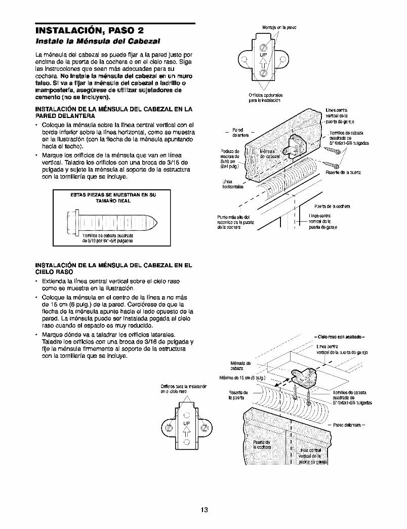
INSTALACION, PASO 2Instale la M_nsula del Cabezal
La m_nsula dol cabezal so puode fijar a la pared justo poroncima do la puerta do la cochora o on el ciolo raso. Sigalas instruceionos que scan m_s adecuadas para succehera. No Inotalo la rn_rmula del cabezal on un mumfaleo. St va a flJar la m_neula del cabezal a ladrlllo omamposterra, asegOrese de utlltzar eujotadoree decernento (no so Incluyen).
INSTALACION DE LA MI_NSULA DEL CABF-ZAL EN LAPARED DELANTERA
• Coloque la m_nsula sobro la ITnoacentral vortical conelhorde inferiorsobro la ITneahorizontal, comoso muestraon la ilustraciSn(con la flocha de la m_nsula apuntandohacia ol tocho).
• Marque los oriflcicede la m_nsula qce van on lineavortical, maladrolosofificios con una broca de 3/I6 depulgada y sujoto la m_nsula al soporto de la ostructuracon la tornilloda que ce incluyo.
ESTAS PIEZAS SE MUESTRAN EN SU
TAMA _O REAL
de_1_ per_ -St_pulga_
O_ici_ Gpcioral_parala instalaci_'_
INSTALACION DE LA MENSULA DEL CABEZAL EN ELCIELO RASO
• Extionda la ITnoacentral vorticalsobroel ciolorasocemo ce muostra on la ilustracibn.
• Coloquo la m_nsulaon el controdo la ITnoaa no m_.sde "i5cm (6 pulg.) de la pared. CerciSrose de quo laflooha do la m_nsula apunto hacia el lado opuesto de lapared. La m_nsula puedo cer instaladapegada al cioloraso cuandoel espacioos muyreduoido.
• Marque d6nde va a taladrar los orifioicelatoralos.Taladro los orifioiosconuna broca de 3/16 do pulgada yfije la m_nsula firmomente al soporte do la estructuracon la tornilloria que ce incluyo.
0rifi_ 0s _r_. la Psf_lac_ono cislor3_c
13
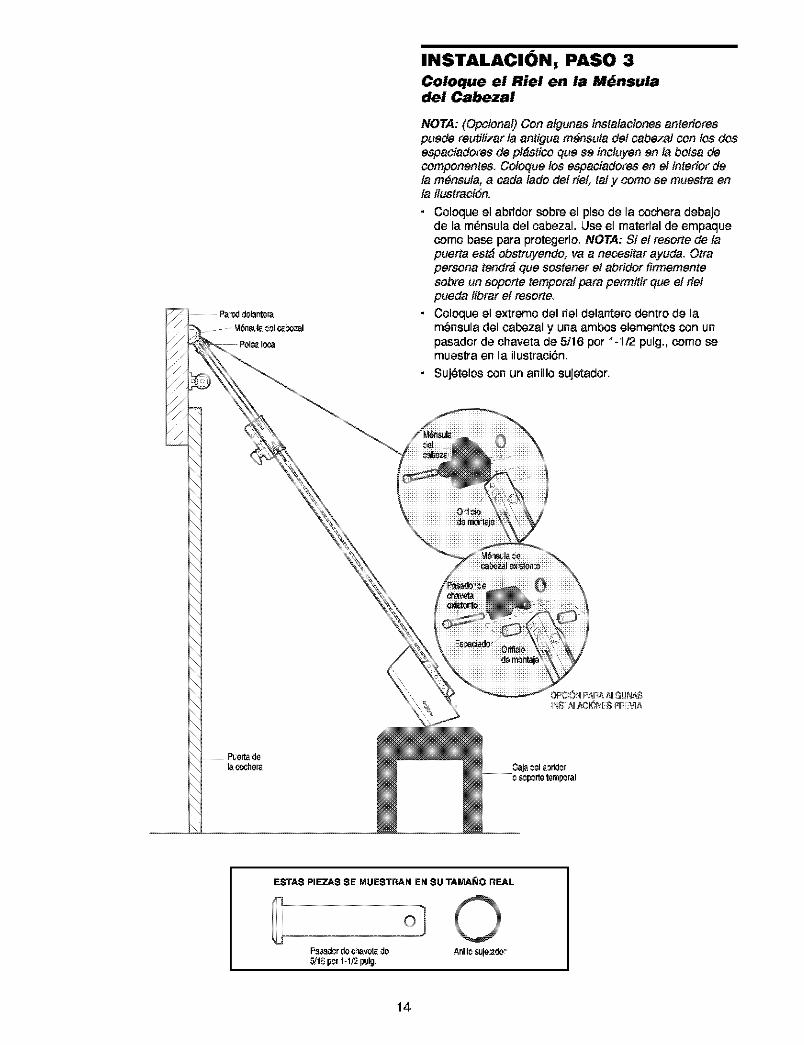
INSTALACION, PASO 3
Coloque el Riel en la M_nsuladel Cabezal
NOTA: (Opcional) Con algunas instalaciones ante#orespuede reutitizar la antigua m_nsuta det oabezal con los dosospaciadores de pl_stico que se incluyen en la botsa decomponentes. Coloque los espaciadores en el interior deta m_nsuta, a cada lade del riet: tat y como se muostra enta ilustraciSn.
• Coloque el abridor sobre el piso de la cochera debajode la m_risula del cabezal, LIse el material de empaquecomo base para protegerlo. NOTA: 5i et resorte de tapuerta es_ obstruyendo, va a neossitar ayude. Otrapersona tendr_ que sostener et abridor firmementesobre un soporte temporal para permitir que et rietpueda tibrar et resorte.
• Coloque el extreme del riel delantero dentro de lam_nsula del cabezal y una ambos elemerttos con unpasador de chaveta de 5/16 per I-I12 pulg., come semuestra en la ilustraci6n.
• Suj_telos con un anillo sujetador.
ESTA$ PIEZA$ SE MUESTRAN EN SU TAMA_JO REAL
F_cr de c,la_te_do Anil¢ slJie'2.dor_1_ pcr1-1Y2pul_
14
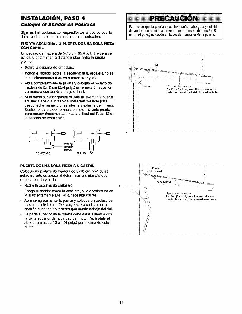
INSTALACION, PASO 4
Coloque el Abridor en Posici6n
Siga las instrucoiones oorrespondientes al ripe de puertade su ocohera, come se muestra en la ilustraoibn.
Paraevitarquela puertadecocherasufradahos,apoyeel rieldelabridordela rnisrnasobreurlpedazode maderade 5x10cm (2×4pulg.) colocadoenlasecci6nsuperiordelapuerta.
PUERTA SECCIONAL O PUERTA DE UNA SOLA PIEZACON CARRIL
tJnpedazo de madera de 5xl 0 cm (2x4 pulg.) le sera de _ayuda al determinar la distanoia ideal entre la puertay el riel.
• Retire la espuma de embalaje.
• Ponga el abfidor sobre la esoalera; si la esoalera no es
Io sufioientemente alta, va a neGesitar ayuda.
• Abra completamente la puerta y coloque el pedazo demadera de 5x10 om (2x4 pulg.) en la secoibn superior,de manera que quede debajo del riel.
• Si el panel superior golpea el trole al levantar la puerta,tire hacia abajo el braze de Iiberacibn del trole paradesconectar las secoiones interna y externa del mismo.Deslico el trole externo haoia el motor. El trole puedepermaneoer desconectado basra el final del Paso I2 dela secoi6n de Instalacibn.
E _0d_ de made_ 58x 10 cm_2x ,I pu_) s6 _!iliza_k_.__6rm_r_r
OONECTP_)0
PUERTA DE UNA SOLA PIEZA SIN CARRIL
Coloque un pedazo de madera de 5x'i0 cm (2x4 pulg.)sobre su lade de ayuda al determinar la distancia idealentre la puerta y el riel.
• Retire la espumade embalaje.• Ponga el abridor sobrela escalera; si la escaleranoes
Iosuficientementealta, va a necositarayuda.• Abraoompletamente la puertay ooloque un pedazode
madera de 5x10 om (2:<4pulg.)sobresu ladeen lasecoibnsuperior,de manera que quede debajo del riel.
• La partesuperiorde la puertadebe estar alineadaconla partesuperiorde la unidaddel motor. No instaleelabridora m0.sde 10 om (4 pulg.)per encima de estepunto.
lad s_n;i_. _,_rr_;':a _8 inst_la¢i6_d_d8 8 t6dh¢.
i i ii
i i
15
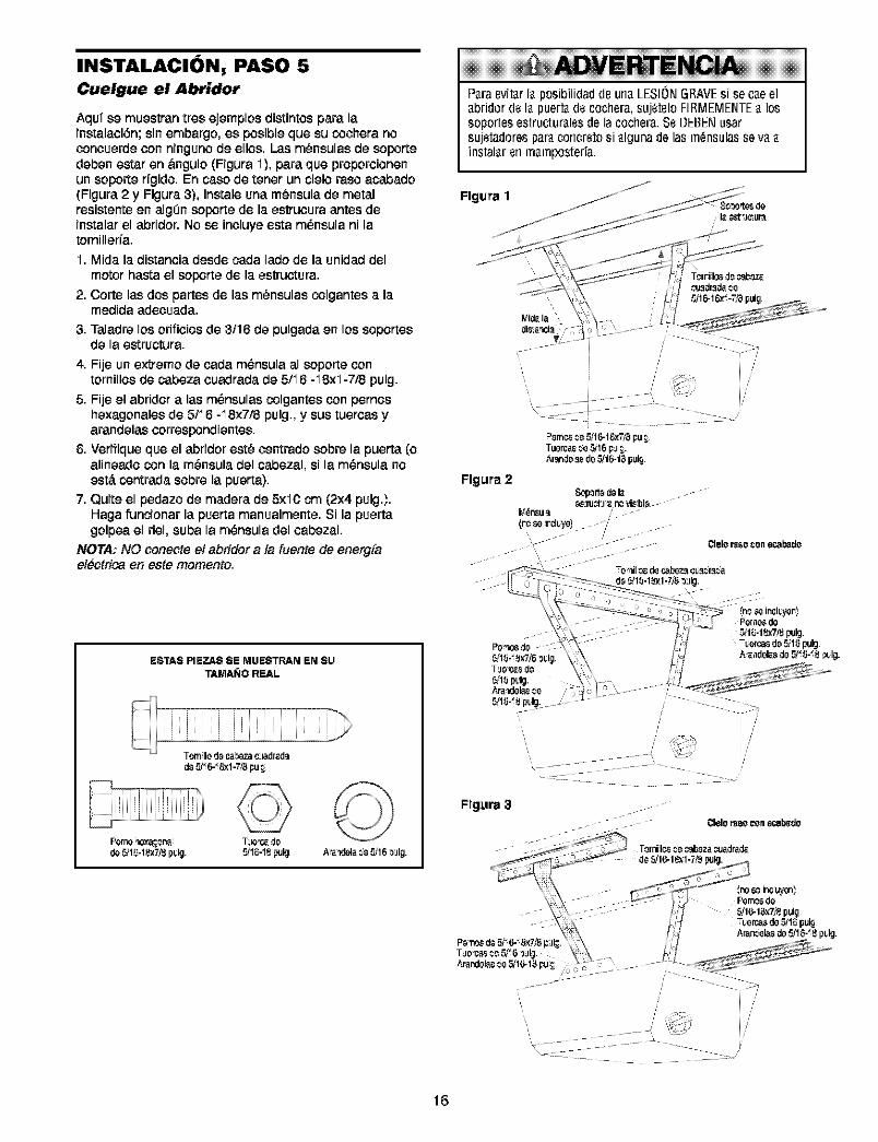
INSTALACION, PASO 5
Cuelgue el Abridor
Aquf se muestran tres ejemplos distintos para lainstalaciGn;sinembargo, es posible que su cochera noconcoerdeconninguno de ellos. Las m_nsulas de soportedeben estar en bngulo (Figura I), para que proporcionenun soporte rfgido. En case de toner un cielo raso acabado(Figura 2 y Figura 3), instale una m_nsula de metalresistente en algOnsoporte de la estrucora antes deinstalar el abddor. No se incluye esta m_nsula ni latornillerfa.
I. Mida la distancia desde cada lade de la unidaddelmotor hasta el Soporte de la estructura.
2. Corte las dos partes de lag m_nsulas colgantes a lamedida adecoada.
3. Taladre los orificios de 3f16 de pulgada en los soportesde la estructura.
4. Fije un extreme de cada mGnsulaal soporte contornillos de cabeza coadrada de 5/I 6 -I8xl-7/8 pulg.
5. Fije el abridor alas mGnsulascolgantes con pernoshexagonales de 5/I6 -I8x7/8 pulg., y sus tuercas yarandelas correspondientes.
6. Verifique que el abridor est6 centrado sobre la puerta (oalineado con la mGnsuladel cabezal, si la mGnsulanoest,. contrada sobre la puerta).
7. Quite el pedazo de madera de 5xi0 cm (2x4 pulg.).Haga funcionar la puerta manualmente. Sila puertagolpea el riel, suba la mGnsuladel cabezal.
NOTA: NO conecteet abridor a ta fuente de energ[ael_ctrica en este memento.
ESTA$ PIEZA$ $E MUESTRAN EN $U
TAMAN0 REAL
C!I dr_.L_
d=£v'_6-_8xl-T/_ pu;
Perno_x_na T!le'_.dode_1_-18x7_pLy. _1_'18pU_ A"a'vJela_s_16 _!llg.
!!!!!!!!!!!!!!!P_raevit_rI_posibilidaddeun_LESIONGRAVEsi sec_eelabridordela puert_de cochera,suj_teloFIRMEMENTEa lossoportesestrucLuralesdela cochera.SeDEBENusarsujetadoresparaconcretosi algunadelasm_nsulasse vaainstalarenmamposteda.
Flgura 2S,c,ported_ I_.
W_n_u_
(re se rclLye) //
_lelo I_80 =on 88alr_dO
Ftgura 3_lelo i_SO con 88ab_dO
16
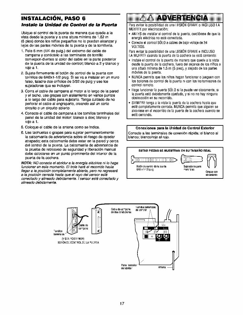
INSTALACION, PASO 6Instale la Unidad de Control de la Puerta
Llbiqueel control de la puerta de manera que quede alavista desde la puerta y a una altura mTnimade 1.52 m(5 pies) donde los niffos peque5os no Io puedan alcanzar ylejos de las partes mSviles de la puerta y de la tornillerfa.I. Pele 6 mm (1/4 de pulg.) del extreme del cable de
campana y cen_ctelo alas terminales de tornillocorrespon-dientes al color del cable en la parte posteriorde la puerta de la unidad de control; blanco a 2 y blanco yrojo a 1.
2. Sujete firmemente el botbn de control de la puerta conternillos de 6ABxl-1/2 plug. Si se vaa instalar en un mutefalse, taladre dos orificios de 5,'32de pulg y use lossujetadores que se incluyen.
3. Corra el cable de campana al motor a Io largo de la paredy el techo, use grapas con aislamiente en varies puntosa Io largo del cable pare sujetarlo. Tenga cuidado de noperforar el cable al engraparlo, creando as{ un cortocircoite o un circuito abierto.
4. Conecte el cable de campana a los torn,los terminales delpanel de la unidad del motor: blanco a dos; blanco yrojo a 1.
5. Coloque el cable de la antena come se lndica.
6. Use tachuelas o grapas pare sujetar permanentementela calcomanfa de advertencla sobre el rlesgo de querieratrapado; esta calcomanfa debe estar en la pared y corcadel control de la puerta. La calcomanfa de advertencla dela prueba de rotroceso de segurldad y Ilberaclbn manualdebe colocarse en un punte prominente del interior de lapuerta de la cochera.
NOTA: NO oone_e el abridor ala energfa ei_clrica ni to hagafoncionar en este momenlo. Et trote har_ et recomdo hastellegar ata posiciSn complelamente abierta, pete no regresar_ata posiciSn cerrada haste que et rayo det sensor est_conectado y aiineado debidamente, t sensor est_ cone_ado yaiineado debidamente.
!iii!iii!iii!iii!iii!iii!iii!iii!iii!iii!i ii !iii!iii! Par_evitarlaposibilid_d(leuna LESIONGRAVEo INCLUSOLAMUERTEper electrocuci_n:° ANTESde instal_relcontroldeI_ puerta,cerciOresede quela
energ[_electricarioest_conecL_da.• Corlecteel controlSOLOacablesdeb_[ovolt_[ede24
VO/TIOS.Par_evitarlaposibilid_d(leuna LESIONGRAVEe INCLUSO/A MUERTEcuarldOlapuert_(le I_cocheraseest;_cerrarldO:• Instaleel controlde I_puert_dem_ner_quequedea I_vista
desdela puert_(le I_cochera,fueradelalcarlce(le los rliffosaurl__ltur,_rn[nirnade 1.5rn (5 pies),y _le[_dodeI_spartesrndvilesde I_puerta.
• NLINCApermit_quelos nihoshagarlfuncionaro jueguenconlos botonesde controlde lapuert_nicon lostr_nsrnisoresdecontrol remote.
• H_gafuncionarI_ puertaSOLOsi lapuedever cl_ramente,silapuertaest_debid_rnente_just_d_,y si r_or_ohay ningun_obstrucci_nensu recorrido.
• SIEMPREteng__ lavistaI_ puert_deI_ cocher_h_staqueest_complet_rnentecerr_da.NLINCAperrnit_que_lguierlse_tr_vieseenel recorrido(le I_puertade la cocher_cuandoseest_cerr_ndo.
Conexionespare la Unidad de Control ExteriorConecte alas terminales de conexibnr_i.pida:el blanco albanco; b anco/roo a reo.
ESTAS PIEZAS SE MUE_N EN SU TAMAle REAL
_'_IIIIIIIIIIIIIIIIIIIIIIIIIIIIIII_ _ __n *_ cor_ d_la_:le_ Suj_:ado_par_
Gr_as _nat8 ami_nto
17
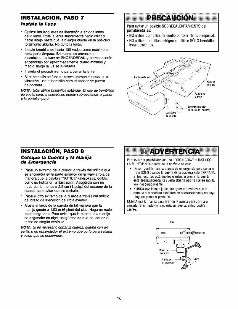
INSTALACION, PASO 7Instale la Luce
• Optima las leng0etasde liberaoi6n a ambos ladosde la lente. Rote la lente suavamente hacia atr&s yhacia abajo basra qua la bisagra quede an la posioi6ntotalmente abierta. No quite la lente.
• Instale bombillo de hasta 100 vatios como m_'_ximoancada portal_.mpara.En cuanto se oonecte laelectrioidad, la luoe se ENCENDERANy permanecor_.nencondidas pot aproximadamentacuatro minutos ymedio; luego la luz se APAGAN.
• Invierta el procodimiento para corrar la lente.
• Si el bombillo se funden prematuramente debido a lavibracibn, use el bombillo para el abridor de puertade oochera.
NOTA; S6lo utilice bombitlos est_nde_ El uso de bomb#los
de ¢uelto ¢orto o especiates puede sobrecalantar el panelo la portal&mpara.
Paraevit_r un posible SOBBECALENTAMIENT0delport_bombill_s:• NO utilicebombill_s de cuello cortoni de tipo especial.• NO utilicebombillas h_16genas.Utilice SOLObombillas
incandescentes.
INSTALACION, PASO 8
Coloque la Cuerda y la Manijade Emergencia
• Pase un axtramode la coerda a tray,s del orificio quase encuentra an la parta superior de la manija roja demanera qua la palabra "NOTICE" (aviso) sea legible,como se indioaan la ilustracibn. Asegdrala con unnudo por Io menos a 2.5 om (1 pulg.) del extramo de lacuerda para evitar qua se rasbale.
• Pasa el otto axtramo de la cuarda a trav_sdal orifioiodel brazo de libaraoi6n del trole exterior.
• Ajusta el largo de la cuerda de tal manara qua lamanija quada a 133 rn (6 pies) dal piso. Haga unnudopara asegurarla. Para avitar qua la cuerda o la manijase enganohe an algo, asegdrase de qua no toquen eltecho de ningL_nvahiculo.
NOTA; Si es necesario cortar ta cuerda, quame con un¢eritlo o un encendedor et extramo qua cort6 para satlarlay evitar clue ae desenrede.
e eNeiAPara8vit_rlaposibilidad(18unaLESIONGRAVEo INCLUS0/A MUER_Esi lapusrta(18lacocheras8caB:
° D8ssrposibls,us8la marlija(188mergenciaparasoltar81trois SOLOcuandola puerta(18la cochsra8st_CERRADA.Si los resortesest_d_bileso rotos,o bisnsi lapuertaest;_desbalanceada,lapuertaabisrtapodriacasrser;_pidayio insspsradaments.
• NUNCAusela marli[ad8 8mergsnciaa rnsrlosqu8laentradaa lacochsra8st_libr8deobstruccionssy riohayaningunapsrsonapresents.
NUNCAus8la rnani[aparatirar d8 lapuertapav_abrirlaocsrrarla.Si81nudo(18la cusrdas8 suelta,ustsdpodr[_caerse.
Tr¢le
18
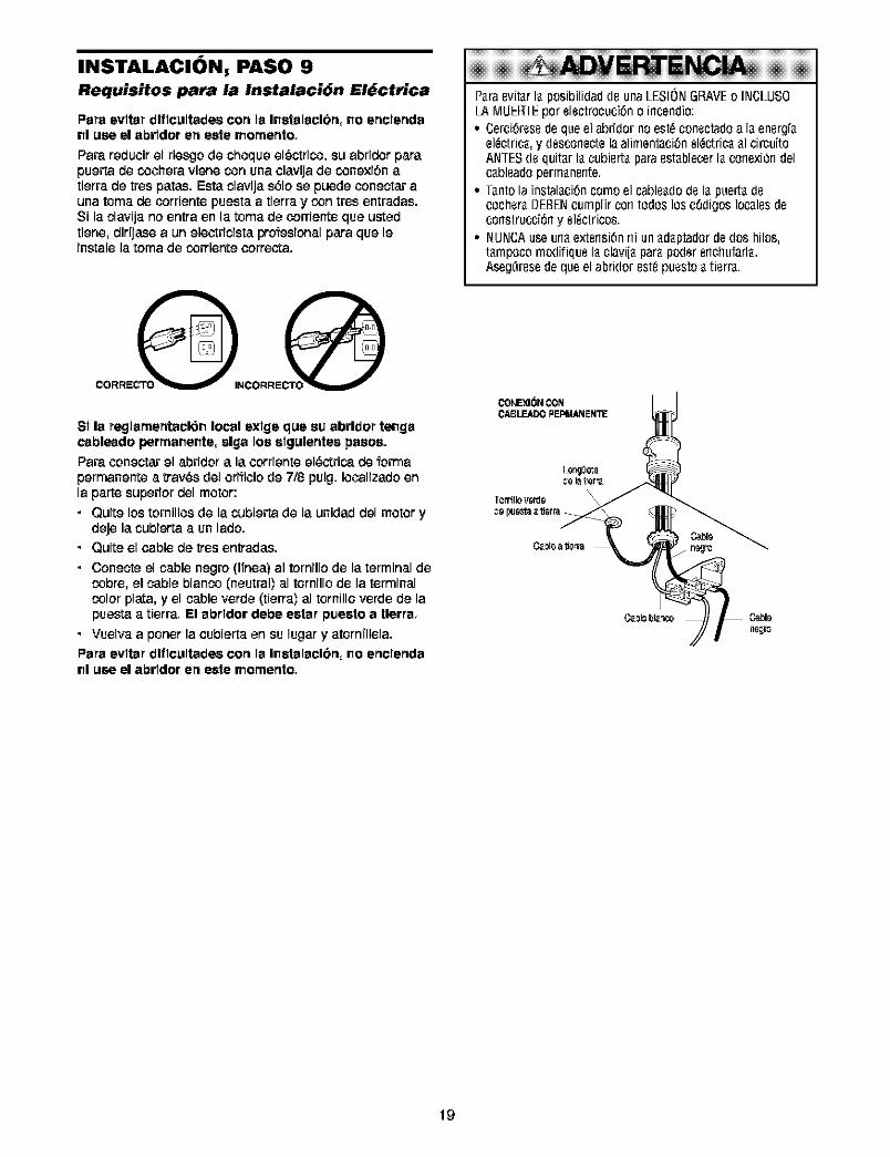
INSTALACION, PASO 9
Requisitos para la Instalaci6n El_ctrica
Para evltar dlflc_Itadee con la l_etalacl6n, _o enclenda[II use el abrtdor en eete mornento,
Para reducir el riesgo de choque el_otrico, su abridor parapuerta de cochera viene con una clavijade conexi6n atierra de tres paras. Esta clavija s61ose puede coneotarauna toma de corrientepuesta a tierra y con tres entradas.Si la clavija no entra en la toma de corrienteque ustedtiene, dir_ase a un electricista pro1_esionalpara que leinstalela toma de corriente correcta.
SI la reglarnerY(acl61_ local exlge que su abrldor tei_gacablemdo perrnai_ei_te, slga los elgulentes pasos.
Para coneotar el abridor a la corriente el_ctrica de formapermanente a tray,s del ofificio de 7/8 pulg. Iocalizado enla parte superior del motor:
• Quite los tornillos de la cubierta de la unidad del motor ydeje la cubierta a un lado.
• Quite el cable de tres entradas.
• Conecte el cable negro (Ifnea) al tornillo de la terminal decobre, el cable blanco (neutral) al tornillo de la terminalcolor plata, y el cable verde (tierra) al tornillo verde de lapuesta a tierra. El abrldor debe estar puesto a tlerra,
• Vuelva a porter la cubierta en su lugar y atornTIlela.
Para evltar dlflc_ltades con la I_etalacl6rt, _o ertclertdanl use el abrldor err eete memento,
¢!AP_raevit_rI_posibilidadde unaLESIONGRAVEo INCLUSO/A MLIEH_Epor electrocuci6noincendio:• Cerci6resedequeel abridornoest_conectadoa I_energf_
el_¢'[ric_,y descone¢'[elaalimentaci6nel_¢'[ric__1circuitoANTESdequit_rI_cubiert_paraest_blecerI_conexi6ndelc_bleadoperm_nente.
• T_ntola instal_ci6ncornoel cable_(Io(le I_ puert_(lecocher_BEBENcumplircon todoslosc6digoslocalesdeconstrucci6ny el_ctricos.
• NUNCAuseurl_extsrlsi6nrliun_d_ptadorde(los hilos,t_rnpocornodifiqueI_clavi[_par_poderenchufarl_.Aseg_resedequeelabridorest_puesto_tierr'a.
19
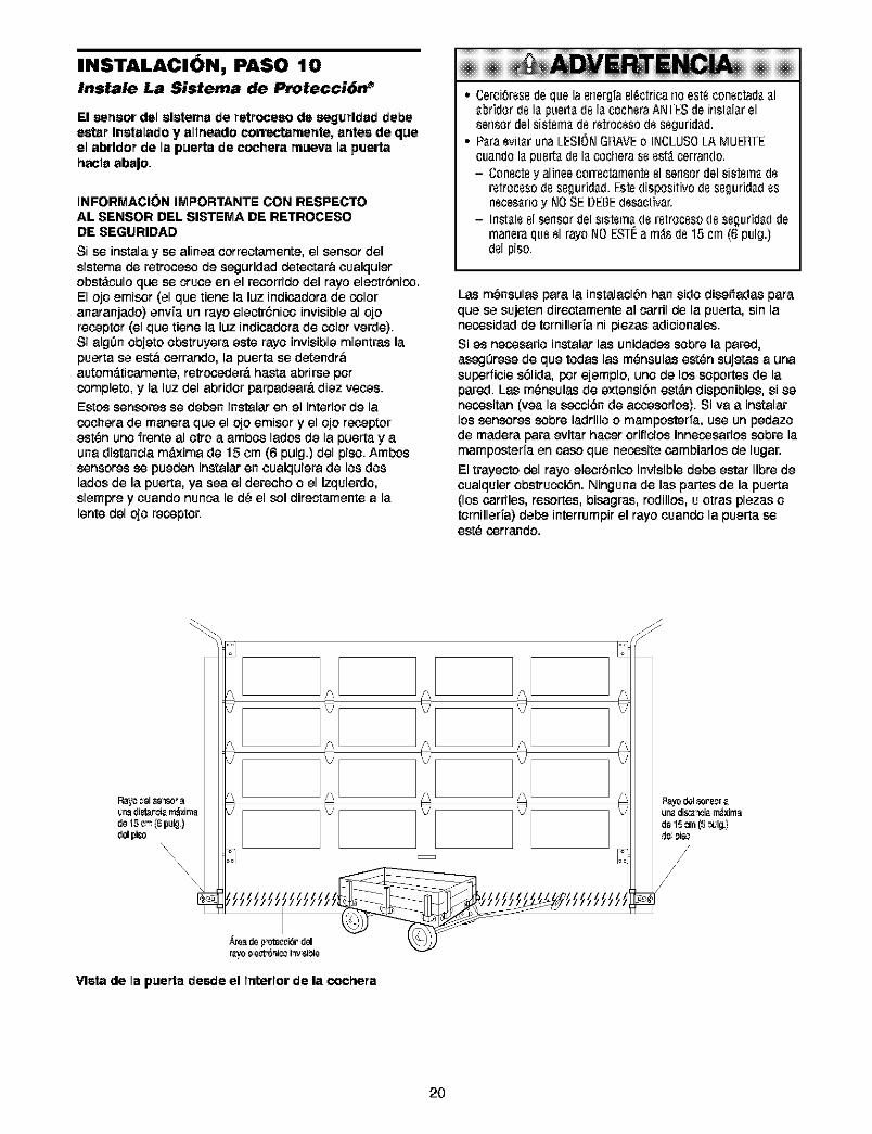
INSTALACION, PASO 10Instale La Sistema de Protecci6n _
El sensor del slatema de re_(rocseo de segurldad debeas'tar ll_atalado y altneado correctarnente, antes de q_eel abrldor be la puerta de cochera mueva la puertahacla abaJo,
INFORMACION IMPORTANTE CON RESPECTOAL SENSOR DEL SISTEMA DE RETROCESODE SEGURIDAD
Si se instalay se alinea oorreotamente, el sensordelsistemade retroceec de seguridad detectara cualquierobst_.culoqua se cruoeen el recorfido del rayo eleotrbnico.El ojo emiecr (el qua tiene la luz indioadorade coloranaranjado) anvfa un rayo elaotr6nico invisible al ojoreceptor (el qua tiene la luz indioadorade color verde).Si algdn objato obstruyera este rayo invisible miantras lapuerta se est& oerrando, la puerta se detendr&autom_.ticamente,retrcoeder&basra abfirse parcompleto, y la luz del abridor parpadear&diez races.Estos sensoresse deben instalaren el interiorde lacoohera de maneraquael ojoemiecr y el ojo receptorest_n uno frente al otto a ambos lados de la puerta y auna distancia m_Lximade 15 am (6 pulg.) del piec.Ambossensoresse pueden instalar en coalquiera de los doslados de la puerta, ya sea el derecho o el izquierdo,siempra y coando nunca le d_ el sol diraotamante a lalente del ojo receptor.
E EN !A• Cerci_resedequelaenergfael_ctricarioest_conectad__1
_bridordeI_ puert_de I_cocheraANTESde inst_l_relsensordelsistem_de retrocesodesegurid_d.
• P_raevit_runaLESIONGRAVE0 INCLUSO/AMUERTEcuandoI_puert_deI_cocheras88st_cerrarldO;- Conectey alineecorrectamenteelsensordelsistemade
retrocesodeseguridad.Estedispositivodeseguridadesneces_rioy NOSEDEBEdesa(,tivar.
- Irlstaleelsensordelsistemaderetrocesode seguridaddernaneraquael rayoNOESTI_a m_sde15 cm(6 pulg.)delpiso.
Las m_nsulas para la instalacibn ban sido diseffadas paraqua se sujeten directamente al carril de la puerta, sin lanecosidad de tornillerfa ni piezas adicionales.
Si as necosario instalar las unidades ecbre la pared,asegL_resede qua todas las m_nsulas est_n sujetas a unasuperficie s61ida,par ejemplo, uno de los ecportes de lapared. Las m_nsulas de extensibn est_.ndisponibles, si senecositan (vea la secci6n de acoeecrios). Siva a instalarlossenecresecbre ladrilloo mamposterfa, use un pedazode maderapara avitarhaoer orificios innecosariosecbre lamamposterTaan oaso qua necosite oambiaflosde lugar.
El trayeoto del rayo elecrbnicoinvisibledebe estar libra decoalquier obstrucoi6n. Ninguna de las partes de la puerta(los oarriles, resortes, bisagras, rodillos, u otras plazas otornillerTa)debe interrumpirel rayo coando la puerta seest_ corrando.
Vista de la puerta dsede el l_erlor de la cochera
2O
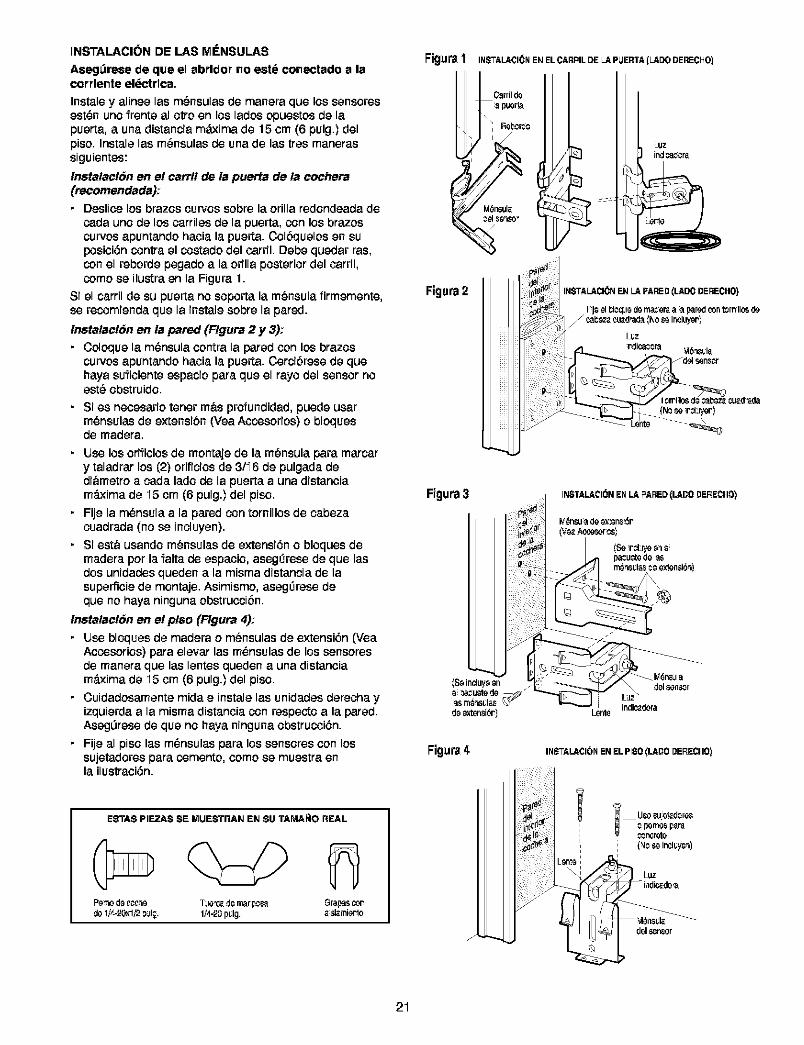
INSTALACION DE LAS MENSULAS
Aseg_rese de que el abrldor no eete conectado a lacorrlente el6ctrlca,
Instale y alinee las m_nsulas de manera que los senseresest_n uno frente al otro en los lades opuestosde lapuerta, auna distancia m&xima de 15 om (6 pulg.) delpied. Instale las m_nsulas de una de las tree manerassiguientes:
Instatacl6n en el cattY!de la puerta de ta cochera(recomendada):• Deslicelos brazes cuwos sobre la orillaredondeada de
cada uno de los oarriles de la puerta, con los brazescurves apuntando hacia la puerta. Colbquelos en suposioi6n contra el costado del carnl. Debe quedar ras,con el reborde pegado a la odlla posterior del cardl,come se ilustra en la Figura 1.
Si el carril de su puerta no soportala m_nsula firmemente,se recomienda que la instale sobre la pared.
Instatacl6n en la paz_d (Flgura 2 y 3):• Coloquela m_nsula oontra la paredcon losbrazes
curves apuntandohacia la puerta. Cercibrese de quehaya suficiente espacio para que el rayo del sensornoest_ obstruido.
• Si es necesariotener m&s pr_fundidad, puede usarm_nsulas de extensibn (VeaAccosorios) o bloquesde madera.
• tJse los orifioios de montaje de la m_nsulapara maroary taledrar los (2) orificios de 3/I 6 de pulgeda dedi&metroa ceda lade de la puerta auna distanciam_Lximade I5 cm (6 pulg.) del pied.
• Fije la m_nsula a la pared con tornillos de cabezacuadreda (no se incluyen).
• Siest& usando m_nsulas de extensi6n o bloques demadera per la falta de espacio, asegl3resede que lasdos unidades queden a la misma distancia de lasuperficiede montaje. Asimismo, asegl3resedeque no haya ninguna obstrucoibn.
Instatacl6n en el p!$o (Flgura 4):
• tJsebloques de madera o m_nsulas de extensi6n (YeaAccosorios)paraelevar las m_nsulas de lossensoresde manera que las lentesquedenauna distanciam_Lximade I5 cm (6 pulg.)del piso.
• Cuidadosamente mida e instalelas unidedesderecha yizquierdaa la misma distanciacon respectoa la pared.AsegL_resede que no haya ningunaobstrucoi6n.
• Fije al pisolas m_nsulas para lossensorescon lossujetedoresparacomento, cored se muestra enla ilustraci6n.
ESTAS PIEZAS SE MUESTP, AN EN SU TAMA_O REAL
CDFe"to de 000't0 T%Ie'C_.pa mar pOea Grap_ o_
Figura1 INS'ALA¢I_N EN EL CARRILDE L.&PIJEFRA{l.AOODERECHO)
I Oarrilde
Figura2
Figura3
Figura# INSTALA¢ION EN EL PIe0 (LADO DERECHO)
Luz
pal _neor
21
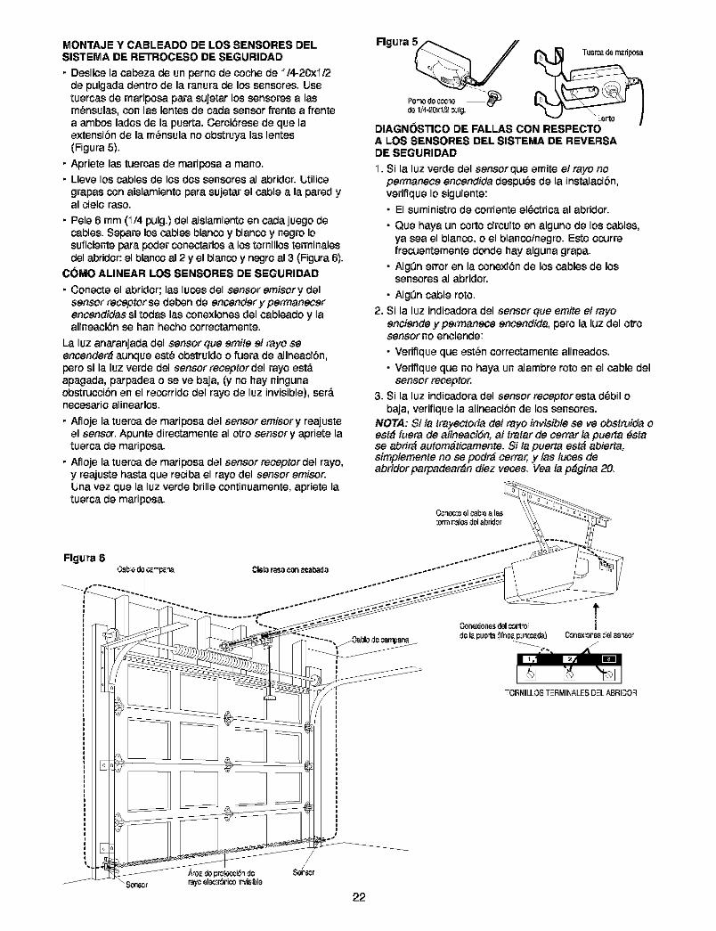
MONTAJE Y CABLEADO DE LOS SENSORES DELSISTEMA DE RETROCESO DE SEGURIDAD
• Deslicela cabeza do un perno do coche do I/4-20xi/2do pulgada dentro do la ranura do los sensores.Usetuercas do mariposa para sujetarlos sensoresa lasm_nsulas, con las lentes do cada sensor frente a frentea ambos lades do la puerta. Cerci6rese do que laextensibn do la m_nsula no obstruya las lentes(Figura 5).
• Apriete las tuercas do mariposa a mane.• Lleve los cablesdo los dos sensores al abridor.IJtilice
grapas con aislamiento para sujetar el cable a la pared yal cielo raso.
• Polo 6 mm (I/4 pulg.) del aislamientoon cada juego docables. Separe los cables blanco y blanco y negro Iosuficiente para pealerconectarlosa los tornillca terminalesdel abridor:el blanco al 2 y el blancoy negroal 3 (Figura 6).
COMe ALINEAR LOS SENSORES DE SEGURIDAD
• Congcte el abridor; las lucos del seceoremisory delsensor receptor so deben do encender y permanecerencendidas si todas las conexiones del cableado y laalineaciSn so ban heche correetamente.
La luz anaranjadadel sensor que emite ei rayo seencender_ aunque est_ obstruido o fuera do alineacibn,pete si la luz verde del sensor receptor del rayo est,.apagada, parpadea o so ve baja, (y no hay ningunaobstrucoibnon el recorrido del rayo do luz invisible), ser_.necesario alinearlca.
• Afloje la tuerca do mariposa del sensoremisory reajusteel sensct. Apunte directamente al otto sensory apriete latuerca do mariposa.
• Afloje la tuerca do mariposa del sensorreceptor del rayo,y reajuste basra que reciba el rayo del sensoremisor.IJna vez que la luz verde brille continuamente, apriete latuerca do mariposa.
FIglJraTu_r_ de rr_dposa
DIAGNOSTICO DE FALLAS CON RESPECTOA LOS SENSORES DEL SISTEMA DE REVERSADE SEGURIDAD
I. Si la luz verde del sensorque emite elreyo nopermanece encendida despu_s do la instalacibn,verifique Io siguiente:
• El suministro do corriente el_ctrica al abridor.
• Que haya un corto circuito on alguno do los cables,ya sea el blanco, o el blanco/negro. Esto ocurrefrecuentemente donde hay alguna grapa.
• AIg_n error on la conexi6n do los cables do lossensores al abridor.
• AIgQn cable rote.
2. Si la luz indicadora del sensor que emite et reyoenciende ypermanec, e encendida, pore la luz del ottosensor no enciende:
• Verifique que est_n correctamente alineados.
• Verifique que no haya un alambre rote on el cable delsensor recepPo_
3. Si la luz indicadora del sensor receptor esta d_bil obaja, verifique la alineacibn do los sensores.
NOTA: Si ta trayectoria det reyo invisible seve obstmida oest_ fuera de atineaciSn, at tretar do cerrer ia puerta _stase abrir_ autom_ticamente. Si ta puerta est_ abierta:simptemente no se podr_ cerrer, y tas lutes deabridor parpadear_n diez veces. Vea ia p_gina 20.
FIglJra 6
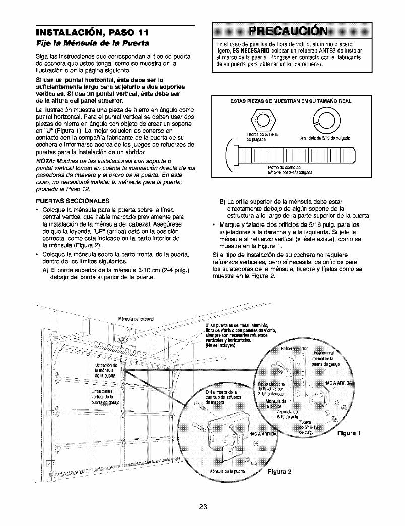
INSTALACION, PASO 1 1Fije la M_nsula de la Puerta
Siga las instrucoionas qua ¢orrespendan al tipo de puartade cochera qua u_ad tenga, como sa muastra an lailustracibn o an la pdgina siguiente.
SI usa un puntal horizontal, este debe sar Ioauflclenternente largo para auJetarlo a dos soporteavertlcalsa. SI usa un purdal vertical, este debe sarde la altura del panel superior.
La ilustraci6n muestra una plaza de hierro en angulo comopuntal horizontal, Para el puntal vertical se daben usar dospiazas de hiarro an _.ngulo con objeto de craar un soporteen "J" (Figura 1). La major solucibn es ponersa encontacto con la compafiTa fabricante de la puerta de succohara a informarse acorca de los juagos de refuerzos depuartas para la instalaci6n de un abddor.
NOTA: Muchas de las instalaciones con soporte opuntal vertical toman en ¢uenta la instalaciSn directa de lospasadores de chaveta y et brazo de la pueda. En este¢aso, no necesitar_ instalar ta m_nsuta para la pueda;proseda al Paso 12.
PUERTAS SECCIONALES
• Coloque la m_nsulapara la puerta sobrala I{nsacentral verticalqua habTamarcadopraviamente parala instalaci6n de la m_nsula del cabezal. Asag_rasede qua la leyanda "ljp" (arriba) est_ an la posici6ncorracta, como eat& indicado en la parta interior dela m_nsula (Figura 2).
• Coloque la m_nsula sobre la parts frontal de la puarta,dantro de los I{mitessiguiantes:A) El borde superior de la m_nsula 5-f0 cm (2-4 pulg.)
debajo dal horde superior de la puarta.
En 81caso de puertas de libra de vidrio, alumirlio o acsroligero, ES NECESARI0colocar url refusrzo ANTES de instalar81marco d8 la puerta. Pdngaseen contacto corl el fabricant8de su pusrta para obtsnsr un kit d8 rsfuerzo.
ESTA$ PIEZA$ $E MUESTPJ_N EN $U TAMA_IO REAL
B) La orilla superior de la m_nsula dabe estardirectamente debajo de algQn soporta de laastructura a Io largo de la parta superior de la puerta.
• Marqueytala_redosorificiosda51f6pulg. paralossujetadoras a la daracha y a la izquiarda. Sujete lam_nsula al rafuerzo vertical (si _sta exista), como samuastra en la Figura f.
Si el tipo de instalacibn de su cochera no requiererafuarzos varticales, pero si necosita los orificios paralos sujatadoras de la m_nsula, taladra y ffjalos como samuestra en la Figura 2.
Flgura 1
23
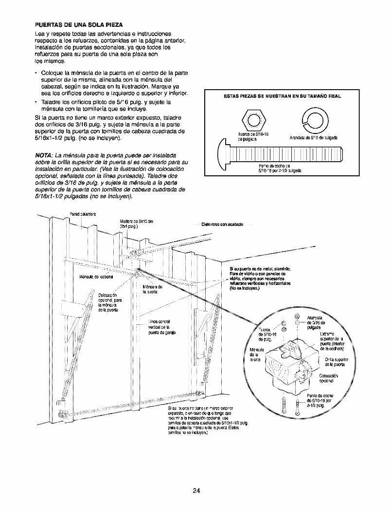
PUERTAS DE UNA SOLA PIEZA
Lea y respete todas las advertencias e instrucoionesrespecto a los r_uerzos, contenidas en la pdgina anterior,Instalacibn de puertas secoionales, ya que todos losrefuerzos para su puerta de una sola pieza sonlos mismos.
• Coloque la m_nsulade la puerta en el centre de la partesuperior de la misma, alineada con la m_nsula delcabezal, segOnse indica en la ilustracibn. Marque yasea los orificiosderechoe izquierdo o superiory inferior.
• Taladre los orificios piloto de 5/I6 pulg. y sujete lam6nsula con la tornilleda que se incluye.
Si la puerta no tiene un marco exterior expuesto, taladredos orificios de 3,'16pulg. y sujete la m_nsula a la partesuperior de la puerta con tornillos de cabeza coadrada de5/I6xi-1/2 pulg. (no se incluyen).
NOTA: La m6nsuia para ta puerta puede ser instatadasobre ta oritia superior de ta puerta si es necesario para suinstaiaciSn en particular. {Vea ta iiustraciSn de cotocaciSnopcional, serfatada con ia ifnea punteada). Taiadre dosorificios de 3/16 de putg. y sujete ia m6nsuta a ia parlesuperior de ia puerta con tomiitos de ¢abeza ¢uadrada de5/!6:<!-1/2 puigadas (no se inciuyen).
ESTA$ PIEZA$ SE MUESTRAN EN SU TAMA_JO REAL
refuerzo$vertlcalesy hodzontal_s(No_ Incluyen.)
24
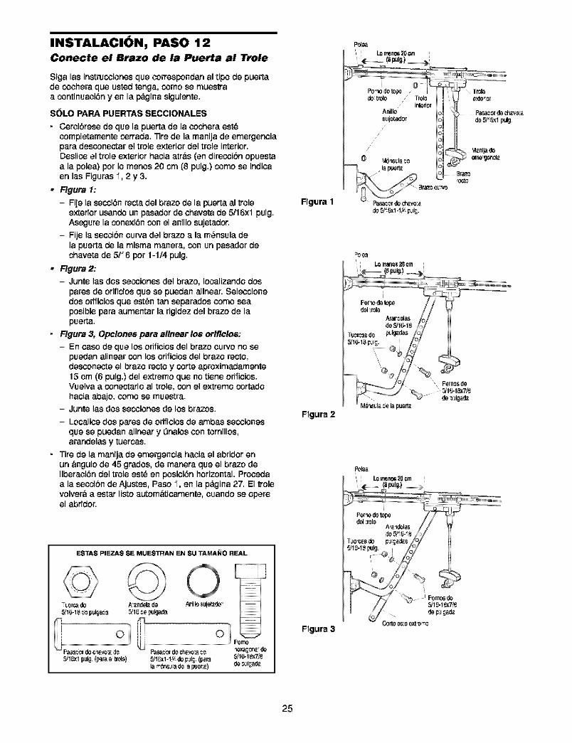
INSTALACION, PASO 12 Polo Conecte el Brazo de la Puerta al Trole
Siga las instrucoiones que correspondan al ripe de puertade cochera que usted tenga, come se muestraa continuaoi6n yen la pdgina siguiente.
SOLO PARA PUERTAS SECCIONALES
• Ceroibrese de que la puerta de la cochera est_completamente corrada. "nrede la manija de emergenciapara desconectar el trole exterior del trole interior.Deslico el trole exterior hacia atr&s (en direcoibn opuestaa la polea) per Io menos 20 cm (8 pulg.) come se indicaen las Figuras I, 2 y 3.
• Flgura 1:
- Fije la secoi6n recta del braze de la puerta al troleexterior usando un pasador de chaveta de 5/16xl pulg.As_Jure la conexi6n con el anillo sujetador.
- Fije la sec:cibn ourva del braze a la m_nsula dela puerta de la misma manera, con un pasador dechaveta de 5/I 6 per 1-1/4 pulg.
• Flgura 2:
- Junte las dos secoiones del braze, Iocalizando dos
pares de orificios que se puedan alinear. Sel_ccionedos orificios que est_n tan separados come seaposible para aumentar la rigidaz del braze de lapuerta.
• Flgura 3, Opc!ones para allnear los orlflclos:
- En case de que los orificios del braze curve no sepuedan alinear con los ofificios del braze recto,descongcte el braze recto y corte aproximadamente15 cm (6 pulg.) del extreme que no tiene orificios.Vuelva a conectarlo al trole, con el extreme cortadohacia abajo, come se muestra.
- Junte las dos secoiones de los brazes.
- Localice dos pares de orificios de ambas secoionesque se puedan alinear y 0nalos con tornillos,arandelas y tuercas.
• Tire de la manija de emergencia haoia el abridor enun &ngulo de 45 grades, de manera que el braze deliberaoi6n del trole est_ en posici6n horizontal. Procedaa la sec:cibn de Ajustes, Paso I, en la p_.gina 27. El trolevolver& a estar listo autom&ticamente, coando se opereel abfidor.
Flgura 1
Flgura 2
Po-_odo top_do trolo / Trolo
,' interiorAnillo
suj_tador
/
ESTAS PIEZA$ SE MUES'mAN EN SU TAMASJO REAL
E 7
-i,6rca de A_ndel_. do ,_J'iIo _uje_de__16-18 _o pulga_ _18 _6 pl#_de
_1_1 pulg_p_ra_trol_) _1_1-1_depid_.(p_r_ _16-1_
Flgura 3
25
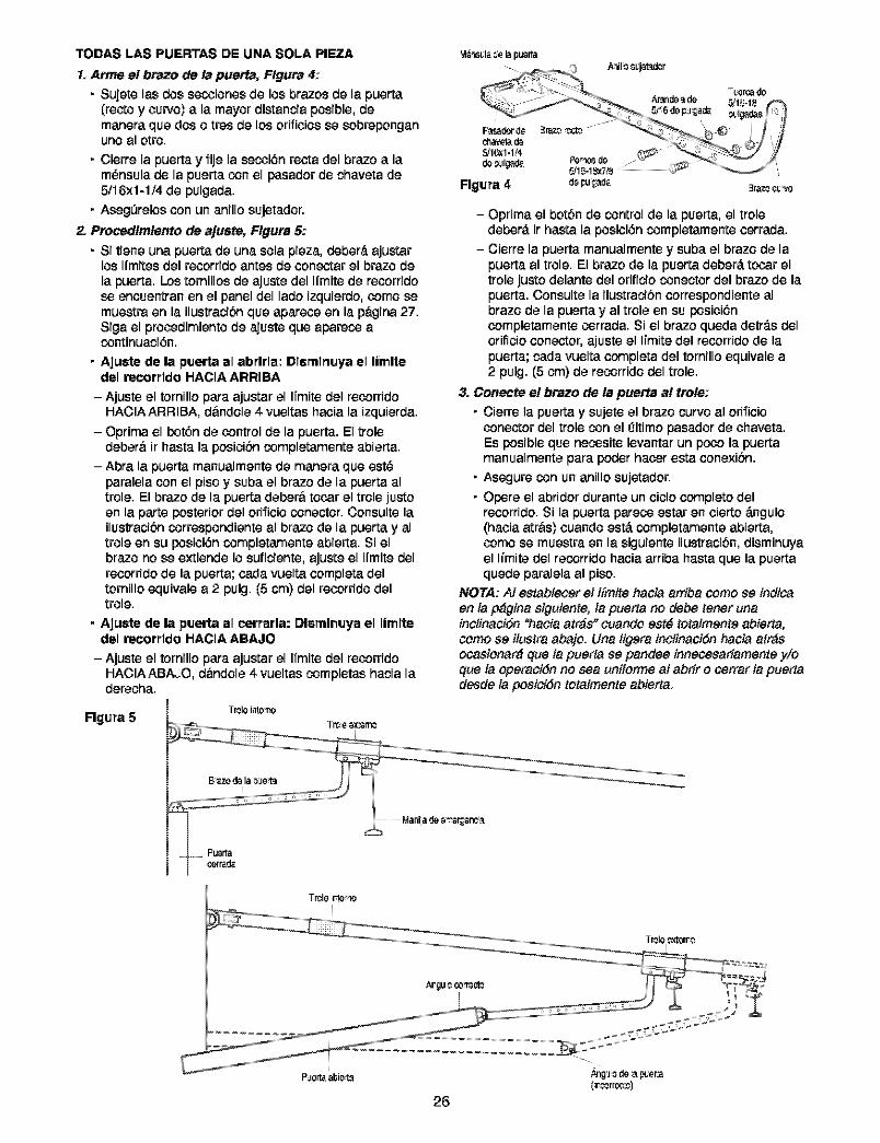
TODAS LAS PUERTAS DE UNA SOLA PIEZA
1. Arme el brazo de la puerta, Flgura 4:
• Sujete las des secoienes de lee brazes de la puerta(recte y cuwe) a la mayer distancia pesible, demanera que des e tres de les erificies se sebrepenganune al etre.
• Cierre la puerta y fije la secoi6nrecta del braze a lam_nsulade la puerta con el pasader de chaveta de5/I 6x1-1/4 de pulgada.
• Aseg_reles con un anille sujetader.
2. Procedlmlento de ajuste, Flgura 5:
• Si tiene una puerta de una sela pieza, deber#,ajustarles Ifmites del recorride antes de conectar el braze dela puerta. Los ternilles de ajuste del Ifmite de recorfidese encoentran en el panel del lade izquierde, como semuestra en la ilustracibn que aparece en la p&gina27.Siga el precedimiente de ajuste que apareco acontinuaci6n.
• Ajuste de la puerta el abrlrla: Dlsrnlrluya el limltedel recorrldo HACIA ARRIBA
- Ajuste el tornille para ajustar el Ifmitedel recorrideHACIAARRIBA, d&ndele 4 vueltashaeia la izquierda.
- Optima el bot6n de control de la puerta. El treledeber& ir hasta la pesJcibncompletamente abierta.
- Abra la puerta manualmente de manera que est_paralela con el pise y suba el braze de la puerta altrele. El braze de la puerta deber&tecar el trele justeen la parts posterior del erificie conecter. Censults lailustracibn correspendiente al braze de la puerta y altrele en su posJcJ6n completamente abierta. Si elbraze ne se extiende le suficiente,ajuste el Ifmite delrecorride de la puerta; cada vuelta completa delternille equivale a 2 pulg. (5 cm) del recorride deltrele.
• Ajuste de la puerta el eerrarla: Dlernlnuya el limltedel recorrldo HACIA ABAJO
- Ajuste el tornille para ajustar el Ifmite del recorrideHACIAABAJO, d&ndele 4 vueltas completas hacia laderecha.
Flgura 5Tt_leinte13o
T_6 ex_r130
- Oprima el betbn de control de la puerta, el treledeber_, ir hasta la pesici6n completamente terraria.
- Cierre la puerta manualmente y suba el braze de lapuerta al trele. El braze de la puerta deber#, tcoar eltrele juste delante del erificie conecter del braze de lapuerta. Censulte la ilustracibn correspendiente albraze de la puerta y al trele en su posici6ncompletamente corrada. Si el braze queda detr_.s delerificie conecter, ajuste el Ifmite del recorride de lapuerta; cada vuelta completa del tornille equivale a2 pulg. (5 cm) de recorride del trele.
3. Conecte e! braze de la puerta a! trote:• Cierre la puerta y sujete el braze curveal erificie
conector del trolecon el 131timepasaderde chaveta.Esposibleque necositelevantarun pcoo la puertamanualmente para poderhaeer es_aconexibn.
• Asegure con unanillo sujetador.
• Opere el abrider duranteun title complete delrecorride. Si la puerta pareco estar en cierte #.ngule(haeia atr&s) cuande est#.completamente abierta,come se muestra en la siguiente ilustracibn, disminuyael limits del recorride haeia arriba hasta que la puertaquede paralela al pise.
NOTA: AI estabteeer el l[mite hacia arriba come se indicaen la p#gina siguiente:la puerta ne debe tener unainctinaciSn "hacia arras" cuande est6 tetalmente abierta,come se ilustra abaje. Una figera inctinaciSn hacia atr_socasienar_ Clueta puerta se pandee innecesariamente y/eque la eperaciSn ne sea unifenne at abrir e ¢errar ta puertadesde la pesiciSn tetatmente abierta.
T_le rte-_o
P!lerta_)J_Je_ ,_g!l 0 de _ p_er:a
(r_rre_e)26
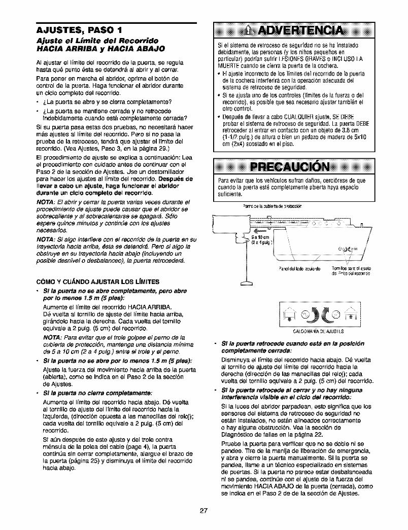
AJUSTES, PASO 1
Ajuste el Limite del RecorridoHACIA ARRIBA y HACIA ABAJO
AI ajustar el Iimite del recorrido de la puerta, se ragulabasra qu6 punto 6sta se detendr& al abfir y al cerrar.
Para poner en marcha el abfidor, optima el botbn decontrol de la puerta. Haga funcionar el abfidor duranteun title complete del recorrido.
• LLa puerta se abre y se cierra completamente?
• LLa puerta se mantiene cerrada y no retrocedeindebidamente cuando est& completamente corrada?
Si su puerta pasa estas dos pruebas, no necesitar& hacerm&s ajustes al Iimite del recorrido. Pete si no pasa laprueba de la retrocoso, tendr_, que ajustar el li'mite delrecorrido. (Vea Ajustes, Paso 3, en la p&gina 29.)
El procodimiento de ajuste se explica a continuaciSn: Leael procodimiento con cuidado antes de continuar con elPaso 2 de la secoiSn de Ajustes. Llse un destornilladorpara hacer los ajustes al li'mite del recorfido. Despuee deIlevar a cabo un aJuete, haga furlclonar el abrldordurartte un clcle complete del recorrldo,
NOTA: Et abrir y cerrarta puerta varias veces durante etprooedimiento de ajuste puede causar que et abridor sesobreca#ente y at sobrecatentarse se apagar_. Sdloespere quince minutes y continSe con toe ajustesnecesafios.
NOTA: Si atgo interfiere con et recorrido de la puerta en sutrayectofia hacia arfiba: dsta se detendr_. Pete si atgo taobstmye en su trayectofia hacia abajo (inctuyendo unposibte de,snivel o desbatanoeo): la puerta retroceder_.
C(_MO Y CUAHDO AJUSTAR LOS L|MITES
• S! la puerta no se abre completamente, pete abreper !o menos 1.5 m (5 pies):
Aumente el Iimite del recorrido HACIAARRIBA,
D6 vuelta al tornillo de ajuste del Iimite hacia arriba,gir_.ndolo hacia la derecha. Cada vuelta del tornilloequivale a 2 pulg. (5 cm) del recorrido.
NOTA: Para evitar que el trote gotpee el pemo de la¢ubierta de protecoidn, mantenga una distancia m[nimade 5 a 10 cm (2 a 4 putg.) entre el trote yet pemo.
• St la puerta no se abre per !o menos 1.5 m (5 pies):
Ajuste la fuerza del movimiento hacia arriba de la puerta(abierta), come se indica en el Paso 2 de la secoibnde Ajustes.
• S! la puetta no clett_ completamente:
Aumente el Iimite del recorrido hacia abajo. D6 vueltaal tornillo de ajuste del li'mite del recorrido hacia laizquierda, (direcci6n opuesta alas manecillas del reloj);carla vuelta del tornillo equivale a 2 pulg. (5 cm) delrecorrJdo.
Si a0n despu6sde este ajuste y del trole contram6nsula de la polea del cable (page 4), la puertacontin0a sincerrar completamente, alargue el braze dela puerta (pdgina 25) y disminuya el Iimite del recorridohacia abajo.
!!!!!!!!!!!!!!!!!!!!!!!!!!!!!!!!!!!!!!!!!!!!!!!!!!!!Siel sistemader_trocssods ssguridadrioss flairlstaladodebidarnsnte,laspersonas(y los nihospsqushosenparticular)podrfansufrir LESIONESGRAVESo INCLUS0LAMUEH_EcuarldOss cisrralapusrtads la cochera.• Elajusteincorrectodelos Ifrnitesdsl rscorridode lapusrta
ds lacocheraintsrferir_conla operaci6rladscuadadslsistsmads retrocssodeseguridad.
• Siseajustaunodelos corltrolss0frnitesds la fusrzao delrecorrido),ssposiblequeseanscesarioa[ustartarnbi_rlelotro control.
• Despu_sdeIlevara caboCUALQUIEHajusts,SEDEBEprobarelsisternaderstrocssods ssguridad.LapuertaDEBEretrocedsralsntrarsncontactocon unob[etode3.8cm(1-1,2pulg.)(Isalturao bisnun psdazo(Is ma(Isra(Is5x10crn(2x4) acostadosn el piso.
u iIi6i iiiiiiiiiiiiiiiiiiiiiiiiiiiiiiiiiiiiiiiiiiiiiiiiiiiiiiiiiiiiiiiiiiiiiiiiiiiiiiiiiiiiiiiiiiParaevitar que los vehfoulos sufrarl daf_os,cerci_rsss de quecuarldOla puerta sst_ completamsrlte abierta haya espaciosuficisrlte.
=str¢ _6 I__bie_ d6 __Jt_cci61"
=a_oldolI_.doz_gie'do Tom II0s_ 81_gsted8 '_1_8_61r_rr_¢
• SI la puerta retrocede cuando esta en la poslc!_ncompletamente cerrada:
Disminuya el li'mitedel recorfido hacia abajo. D6 vueltaal tornillo de ajus_e del Iimite del recorrido hacia laderecha (direcoibn de las manecillas del reloj); cadavuelta del tornillo equivale a 2 pulg. (5 cm) del recorrido.
• SI la puerta retrocede at cerrar y no hay n/nguna/nterferenc/a visible en e! clc/o de! recort_do:
Si la lucos del abridor parpadean, estosignifica que lossensores del sistema de retrocoso de seguridadnoest&n instalados,no est&n alineados correctamenteo hay alguna obstrucoiSn. Yea la secoiSndeDiagnSsticode fallas en la p_Lgina22.
Pruebe la puerta para vefificar que no se doble ni sepandee. "13rede la manija de liberacibn de emergencia,y abra y cierre la puerta manualmente. Si la puerta sepandea, Ilame a un t6cnico especializado en sistemasde puertas. Si la puerta no parece estar desbalanceadani se pandea, continL_econ el ajuste de la fuerza delmovimiento HACIAABAJO de la puerta (corrada), comese indica en el Paso 2 de de la secoiOnde Ajustes.
27
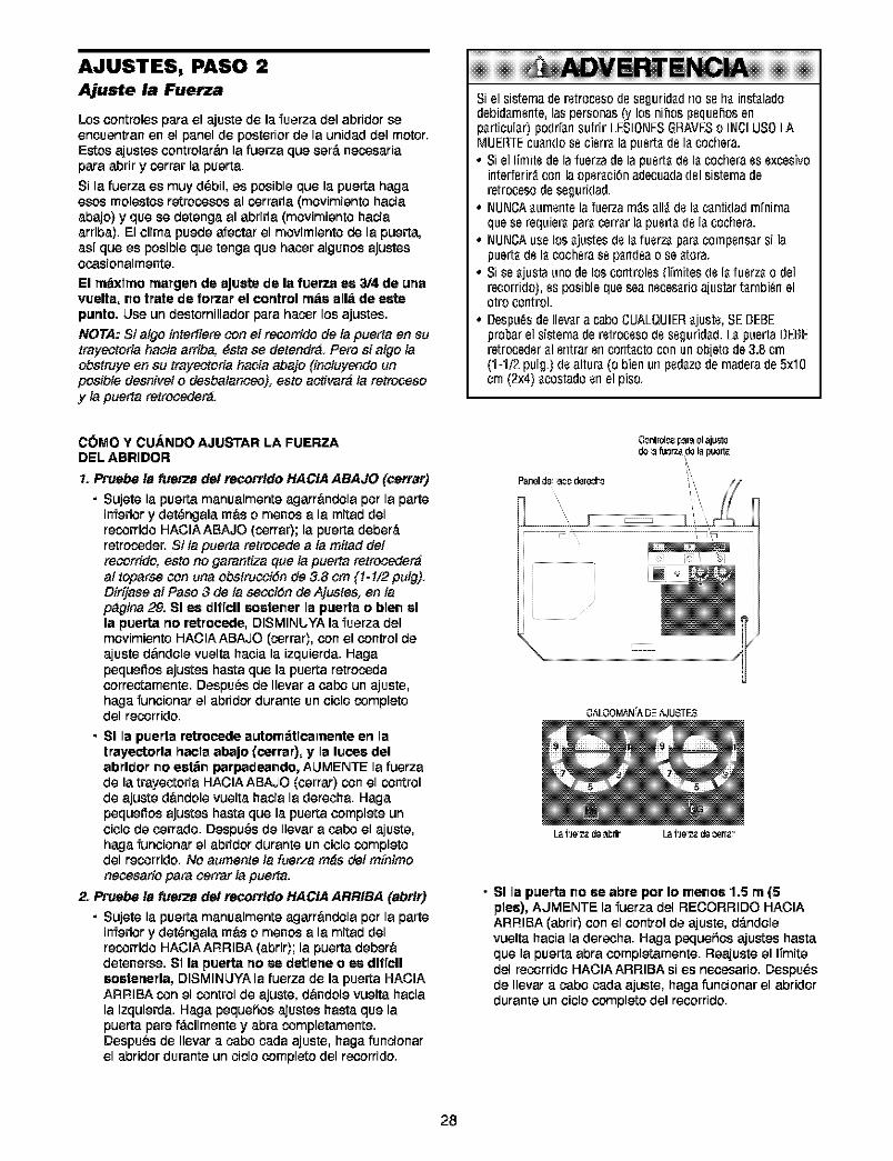
AJUSTES, PASO 2Ajuste la Fuerza
Los controles pare el ajuste de la fuerza delabfiderseencoentran en el panel de posterior de la unidad del motor.Estos ajustescontrolar&n la fuerza que ser_.necosariapare abfir y corrar la puerta.
Si la fuerza es muy d_bil, es posible que la puerta hagaesos molestes retrocosos al corrarla (mevimiente haciaabajo) y que se detenga al abfirla (movimiento haciaarriba). El clime puede afeotar el mevimiento de la puerta,asf que es posible que tenga que hacer algunos ajustesocasionalmente.
El rn_xlrno rnargerl de eju_e de la fuerza ee 3/4 de urlavuella, no Irate de for'zar el control rn_s all_ de estepurtlo. Llse un destornillador para hacor los ajustes.
NOTA: Si atgo intediere con el recorrido de la puerta en sutrayectoria hacia amba, _sta se detendr_. Pero si algo laobstrJye en su trayectoria hacia abajo {inctuyendo unposibte desnivei o desbatanceo): esto activar_ la retrocesoy la puerta retroceder_.
Siel sistemaderetrocesode Segurid_drio$8h_irlst_ladodebid_rnsnte,laspersonas(y los nihospsqushosenp_rticul_r)podr[_nsufrir LESIONESGRAVESo INCLUS0LAMUER_Ecu_ndoss cisrr_lapusrt_ds I_ cochera.° Siel ITmitsdela fuerzadela pusrt_ds I_cocherass sxcesivo
interfsrir_con laopsr_ci_nadecuadadsl sisternaderetrocesodeseguridad.
° NUNCA_urnsntela fuerzam_s_11_ds I_c_ntidadrn[nirnaquese requier_par_cerr_rlapusrt_ds I_cochera.
° NUNCAuselos _justesds I_fusrz_par_compsns_rsi lapuert_ds I_cochsrassp_rldsao se_tora.
° Sise_justaunodelos controlss(l[rnitesds I_fusrz_o delrecorrido),ssposiblequeseansces_rioa[ustart_rnbi_rlelotro control.
° Despu_sdeIlev_ra caboCUALQUIER_justs,SEBEBEprobarelsisternaderstrocssods ssgurid_d.L_puertaBEBEretrocedsr_1sntrarsncont_ctocon unob[etode3.8crn(1-1/2pulg.)ds altur,_(o bienun psd_zodernaderade5x10crn(2x4) _costadosn el piso.
COMO Y CU/_.NDO AJUSTAR LA FUERZADEL ABRIDOR
1. Pruebe la fuerza de! recorrldo HACIA ABAJO (oerrar)
• Sujete la puerta manualmente agarr&ndola per la parteinferior y det_ngala m&s o menos ala mired delrecorride HACIA ABAJO (corrar); la puerta deber_.retrocoder. Sita puerta retrocede ala mired de/recorrido, esto no garantiza que la puerta retroceder_at toparse con una obstmociGn de 3.8 cm {!-!/2 pulg).Dirfjase al Paso 3 de ta seociSn de Ajustes: en tap_gina 29. SI ee dlficll soslener le puede o blen ella puerta no retrocede, DISMINUYA la fuerza delmovimiento HACIA ABAJO (corrar), con el control deajuste d&ndele vuelta hacia la izquierda. Hagapequeffos ajustes haste que la puerta retrocodacorrectamente. Despu_s de Ilevar a cabo un ajuste,haga funcienar el abridor durante un cicle completedel recorrido.
• SI le puede retrocede eutom_tlcerne_e err letrayectorla haole abaJo (cerrar), y le luces delabrldor no eet;_nparpadeando, ALIMENTE la fuerzade la trayectoria HACIAABAJO (cerrar) con el controlde ajuste d&ndole vuelta hacia la derecha. Hagapequeffos ajustes haste que la puerta complete uncicle de cerrade. Despu_s de Ilevar a cabo el ajuste,haga funcienar el abridor durante un cicle completedel recorrido. No aumente la fuerza m_s del m[nimonecesariopare cerrar la puerta.
2. Pruebe la fuerza de/recorrldo HACIA ARRIBA (abrlr)
• Sujete la puerta manualmente agarr&ndolaper la parteinferiory det_ngala m&so menos a la mired delrecorride HACIAARRIBA (abrir); la puerta deber&detenerse. SI la puerta no se de_leneo ee dlficlleostenerla, DISMINJYA la fuerza de la puerta HACIAARRIBA con el control de ajuste, dandole vueltahaciala izquierda.Haga peque_iosajustes haste que lapuerta pare f_.cilmentey abra completamente.DespuGsde Ilevar a cabe cada ajuste, haga funcionarel abridor durante un ciclo complete del recorfido.
Paneld= _oo dere_'o
O0ntrol_sp_u_ol aju_'t_
L_ f!le_ d_ _l_dr L_ f!le_ d_ _rr_._
• SI le puerta no se abre par Io menos 1.5 m (5pies), ALIMENTE la fuerza del RECORRIDO HACIAARRIBA (abrir) con el control de ajuste, d_.ndolevuelta hacia la derecha. Haga peque_ies ajustes hasteque la puerta abra completamente. Reajuste el ITmitedel recorride HACIA ARRIBA si es necesafio. Despu_sde Ilevar a cabe cada ajuste, haga funcionar el abriderdurante un ciclo complete del recorfido.
28
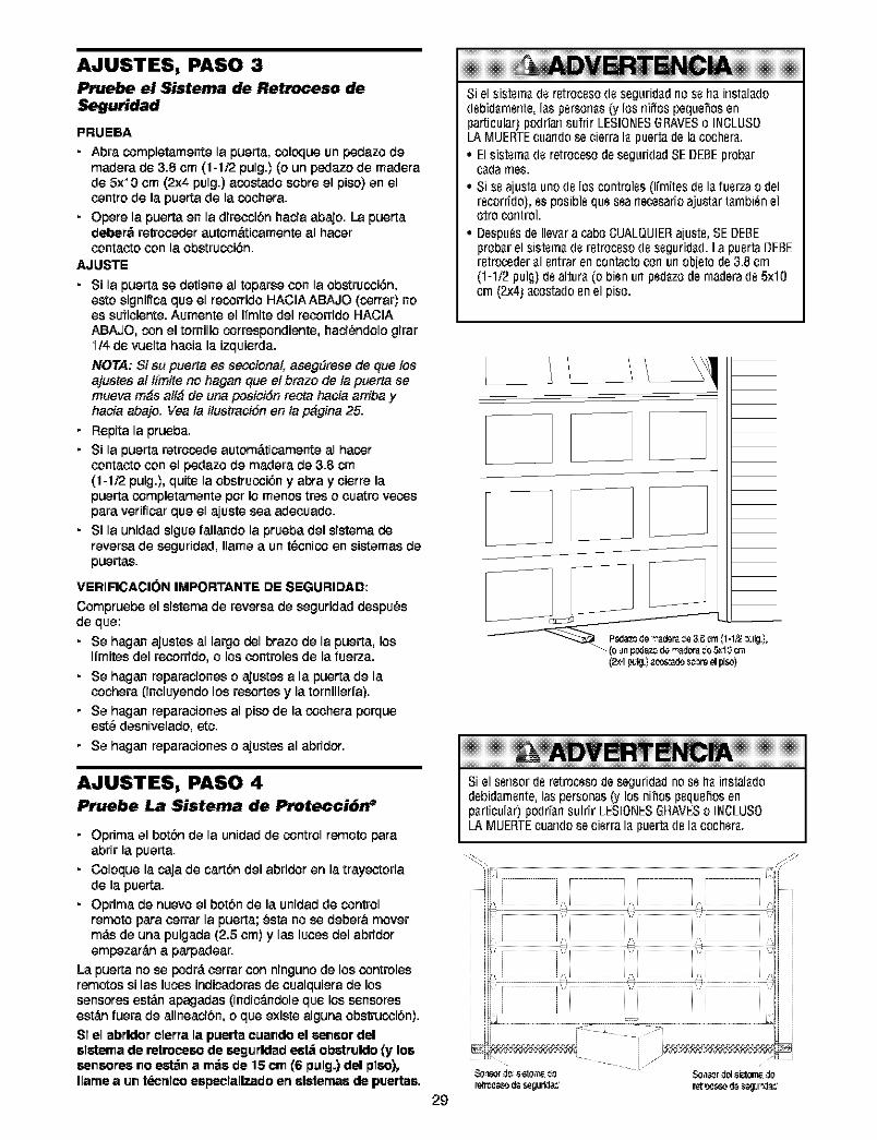
AJUSTES, PASO 3Pruebe el Sistema de Retroceso deSeguridad
PRUEBA
• Abra completamente la puerta, coloque unpedazo demadera de 3.5 om (1-1/2 pulg.) (o un pedazo de maderade 5)('i0 om (2x4 pulg.) acoetado sobre el piso) en elcentre de la puerta de la coohera.
• Opere la puerta en la direcoibn hacia abajo. La puertadeber6 retrooeder autom&tioamenteal haoeroontacto con la obstrucoi6n.
AJUSTE
• Si la puerta se detiene al toparse con la obstrucoi6n,eeto significa que el recorrido HACIA ABAJO (corrar) noes sufioiente. Aumente el Ifmite del reoorrido HACIA
ABAJO, con el tornillo correspondiente, haci_ndolo girarI/4 de vuelta haoia la izquierda.
NOTA: Si su puerta es secoionat, asegSrese de clue losajustes al t[mite no hagan clue et braze de ta puerta semueva m_s alt_ de una posici6n recta hacia arriba yhacia abajo. Vea ta itustraciSn en ta p_gina 25.
• Repita la prueba.
• Si la puerta retrocede autom_.ticamente al hacoroontacto con el pedazo de madera de 3.5 cm(1-1/2 pulg.), quite la obstrucoi6n y abra y oierre lapuerta completamente per Io menos tres o ouetro vecospara verificar que el ajuste sea adecoado.
• Si la unidad sigue fallando la prueba del sistema dereversa de seguridad, Ilame a un t_onico en sietemas depuertas.
VERIFICACION IMPORTANTE DE SEGURIDAD:
Compruebe el sistemade reversa de seguridad despu_sde que:
• Se hagan ajustes al largo del braze de la puerta, losIfmites del recorrido, o los oontrolesde la fuerza.
• Se hagan reparaciones o ajuetes a la puerta de laoochera (inoluyendo los resertes y la tornillerfa).
• Se hagan reparaciones al piso de la coohera porqueeet_ desnivelado, etc.
• Se hagan reparaciones o ajuetes al abridor.
AJUSTES, PASO 4Pruebe La Sistema de Protecci6n _
• Oprima el botbn de la unidad de control remote paraabrir la puerta.
• Coloque la caja de cartbn del abridor en la trayectoriade la puerta.
• Oprima de nuevo el botbn de la unidad de controlremote para oerrar la puerta; _sta no se deber&movermds de una pulgada (2.5 ore)y las luoes del abridorempezar_.na parpadear.
La puerta no se podr_,oerrar con ninguno de los controlesremetos si las lucos indicadorasde coalquiera de lossensores est_.napagadas (indic_.ndoleque los sensoreseet_.nfuera de alineaci6n, o que existe alguna obstrucoi6n).SI el abrldor clerra la p_erta c_ando el sensor delelstema de retrocesode segurldade_t_ obstruldo(y lossensores no est_n a m6e de 15 cm (6 pulg.) del plso),Ilamea un t_cnlco eepeclallzadoen eletemae de puertae,
29
E ENC!ASiel sistsm_ds rstrocssods segurid_driossh_irlst_l_dodsbid_rnsnte,I_spsrson_s(y los rfiffospequehosenparticular)podfiarlsufrir LESIOr'JESGRAVESo INCLUS0LAMUERTEcuandosecierraI_ puertade lacochsr_.• Elsistsm_ds retrocesodeseguridadSEDEBEprober
c_darues.• Sissa[ustaunods los controlss(l[rnitesds I_fusrzao del
rscorrido),ssposiblsqus ssanecesarioajust_rt_rnbi_nelotrocontrol.
• DespudsdeIlevara caboCUALQUIERajusts,SEDEBEproberel sistsm_ds rstrocssods ssgurid_d.LapusrtaDEBErstroceder_1srltraren contactocorlurlob[etode3.8cm(1-1/2pulg)ds altur_(obisn un psd_zodernaderads 5x10crn (2x4)acostadosn elpiso.
Siel ssnsords retrocssodeseguridadnossh_ instal_dodebid_rnsnte,laspersonas(y los nihospsqushosenp_rticul_r)podr[_nsufrir LESI0r'JESGRAVESo INCLUS0/A MUERTEcuandosecisrra I_ puert_ds I_ cochsr_.
' ii,
ill i
ill ¸¸¸ :, iii i
ill L J L i i i i i
'_or d_ s st_r_. _
retmc_o d_ segufida_
/
Sen_r d_l sJetorn_ d_
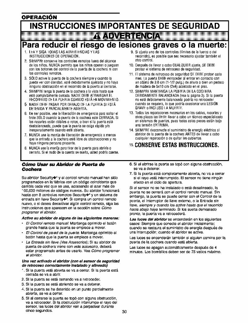
OPERACION
INSTRUCCIONES IMPORTANTES DE SEGURIDAD
E ENC!Para reducir el riesgo de lesiones graves o la muerte:1. LEAY SIGATODASLASADVERTENCIASY LAS
INSTRUCCIONESDEOPEP,ACION.2. SIEMPREconservelos controlesremotosfueradelalcarlce
delos rlifios.NUNCAperrnitaquelos nihosopererlo jueguerlcon los botones(lelcontrol (le lapuertade la cocheraniconlos corltrolesrernotos.
3. SOLOactivela puertade lacocherasiempreycuandolapuedavercon claridad,est_debidarnerlteajustaday riohayaningunaobstrucci6nenel recorridodelapuertaal cerrarse.
4. SIEMPREtengalapuertade lacocheraa lavistahastaqueest_cornpletarnentecerrada.NADIEDEBEATRAVESARELRECORRII]OBELAPUERTACUANBOESTAENMOVIMIENTO.
5 NADIEDEBEPASARPORDEBAJODE/A PUERTASI EST._,DETENIDAY PARCIALMENTEABIERTA.
6. Deserposible,usela liberaci6ndeemergenciaparasoltareltrole SOLOcuandolapuertadela cocheraest_CEBBAI]A.Silos resortesest;_rld_bileso rotes,o bier1si la puertaest&desbalanceada,puedequela puertase caigar_pidayioirlesperadarnerltecuarldOest_abierta.
7. NUNCAusela manijadeliberaci6rldeernergerlciaarnerlosquelaentradaa lacocheraest_libredeobstruccionesy nohayaningunapersonapresente.
8. NUNCAuselarnarlijaparaNrardelapuertaparaabrirlaoterraria.Siel nudedelacuerdasesuet[a,ustedpodrfacae_e.
9. Siajustaurlode loscorltroles(limitasde lafuerzao delrecorrido),esposiblequeseanecesarioajustartarnbi_nelotro control.
10. I]espu_sde IlevaracaboCUALQUIERajuste,SEI]EBEprobarelsisternaderetrocesodeseguridad.
11. ElsisternaderetrocesodeseguridadSEI]EBEprobarcadarues.LapuertaDEBEretrocederal entrarencontactoconunobjetode3.8 crn (1-1/2pulg.)dealturao bienunpedazodernaderade5x10 cm(2x4)acostadoenelpiso.
12. SIEMPREMANTENGALAPUERTADELACOCHERADEBIDAMENTEBALANCEADA(yeala p_gina3).Si la puertanoest;_debidamerltebalanceadapodriano retrocedercuandose requiera,Io quepodriaocasionarunaLESIONGRAVEo INCLUSO/AMUEItTE.
13. Todaslas reparacionesnecesariasenlos cables,resortesyotraspiezaslasOEBEIlevara cabount_crlicoespecializadoerlsistarnasdepuertas,puestodasestaspiezasest_nbajounatensi6nEXTREMA.
14. SIEMPREdesconecteel surninistrodeenerg[aeld¢¢ricaalabridorde lapuertadelacocheraANTESdeIlevara cabocualquierreparaci6no(le quitarlascubiertas.
CONSERVEESTASINSTRUCCIONES.
C6mo Usar su Abridor de Puerta deCochera
Su abridorSecurity_l,_y el control remote manual han sideprogramados en la f&bricacon un c6digo coincidente quecambia cada vez que se usa, accosando al azar m&sde"i00,000 millones de cbdigos nuevos. Su abridor funcionar_.basra con 8 controles remotos Secority,I." y un sistema deentrada sin Ilave Security4-_.Si compra un control remotenuevo, o si desea desactivar algOncontrol remote, siga lasinstrucoionesque aparecen en la secoi6n sobre Cdmoprogramar et abridor.
Active su abrldor de atguna de tas slgulentes maneras;
• EI Centre/remete manua/: Mantenga eprimide el bot6ngrande basra que la puerta se empiece a mover.
• EI Control de pared de la puerta: Mantenga oprimido elbotbn basra que la puerta se empiece a mover.
• La Entrada sin//ave (Vea Acoesorios): Si su abridor depuerta de cochera viene con este acoesorio, deber_.estar programado antes de usarlo. Yea C6mo programaret abridor.
Una vez aetlvado el abrldor (con e! sensor de segurldadde retroceso eor_ctamente Instalado y allneado)"i. Si la puertaest& abierta seva a cerrar. Si la puertaest,.
cerrada se va a abdr.2. Si la puertase est& corrando va a retrocoder.3. Si la puertase est& abriendose va a detener.4. Si la puertase ha detenidoen un puntoparcialmente
abierta, se va a corrar.5. Sial cerrarse la puertase topbcon alguna obstrucoibn,
va a rotroceder.Si la obstrucoibninterrumpeel rayodelsensor,las lutes del abddorvan a parpadeardurantecinco segundos.
6. Si al abrirsela puerta se top6 con alguna obstrucoi6n,se va a detener.
7. Si la puerta est& completamente abierta, no va a cerrarsi el rayo est,. interrumpido. El sensor no tiene ning0nefecto en el ciclo de apertura.
Si el sensorno se ha instaladoo est& desalineado, lapuerta no se corrar_,con el control remote manual. Sinembargo,la puerta se puede corrar con el Control de lapuerta, el Interrupter de Ilaveexterno, o la Entrada sin,ave, siempre y cuando tos active basra que el recorridohacia abajo haya terminado. Si los suelta demasiadopronto, la puerta va a retrocoder_..
Las lutes de! abrldor se enconder&n en los siguientescases:Siempre queconecte el abddor inicialmente;cuandose restaurael suministrode energia despu_sdeuna interrupci6n;coando el abddor se activa.
Las lutes se enconder_.ntambi_nsi alguiencaminaper lapuertade la cochera coando est,. abierta.
Las lutes se apagan autom_.ticamentedespu_sde 4minutes.Losbombilles deben ser de 75 variesm_Lximo.
3O
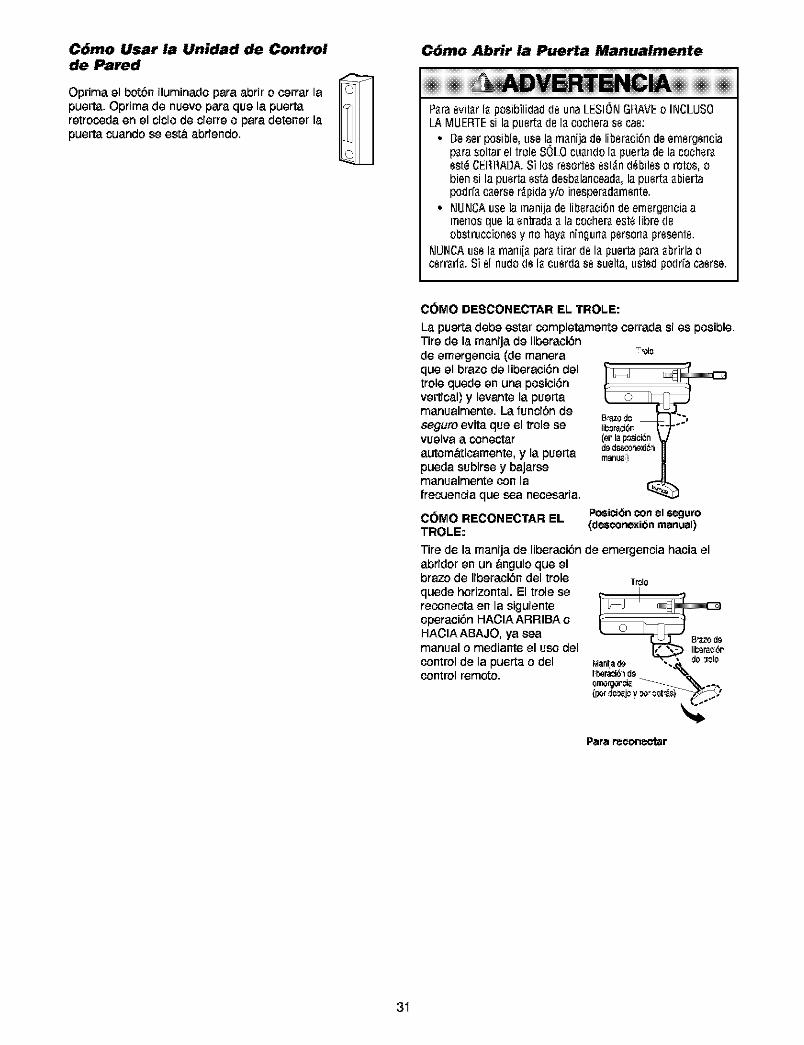
C6mo Usar la Unidad de Controlde Pared
Oprima el botbn iluminado para abdr o cerrar lapuerta. Oprima de nuevo para que la puertaretroceda en el title de cierre o para detener lapuerta cuando se est& abriendo.
C6mo Abrir la Puerta Manualmente
P_raevit_rI_posibilidad(le unaLESIONGRAVEo INCLUS0/A MUER_Esi lapuert_(le I_cocherasecae:
• Beser posible,usela m_nijade liber_ci_ndeemergenciap_rasoltarelVoleSOLOcu_ndoI_ puertadelacocheraest_CEItRABA.Si los resortesest_n(l_bileso rotos,obiensi la puertaest_desb_lancead_,la puert__biertapodr{_c_erser_pidayio inesperad_rnente.
• NUNCAuselamanijadeliber_ci_ndeernergenciaamenosquela entradaa la cocher_est_libredeobstruccionesy no hayaningunapersonapresente.
NUNCAuseI_ rnani[_par_Nrarde I_puertapara_brirlaocerrarl_.Siel nudodeI_ cuerdase suelta,ustedpodr{acaerse.
COMO DESCONECTAR EL TROLE:
La puerta debe estar completamente cerrada si es posible.Tire de la manija de liberaci6n
-_OI0de emergencia (de maneraque el braze de liberaci6n deltrole quede en una posici6nvertical) y levante la puertamanualmente. La funcibn deseguro evita que el trolese lib_raci6rvuelva a Coneotat (er la p_sici_n
de d_o_eyJ_autom&ticamente, y la puerta marius)pueda subirse y bajarse
manualmente con lafrecuencia que sea necesaria.
COMO RECONECTAR ELTROLE:
Posici_nconel s_juro(desconexibn manual)
Tire de la manija de liberaci6n de emergencia hacia elabridor en un angulo que elbraze de liberaci6n del trole tr_lequede horizontal. El trole sereconeeta en la siguienteoperaci6n HACIA ARRIBA o
HACIA ABAJO, ya sea B_zodemanual o mediante el use del
control de la puerta o del de:rolecontrol remote.
Para reconectar
31
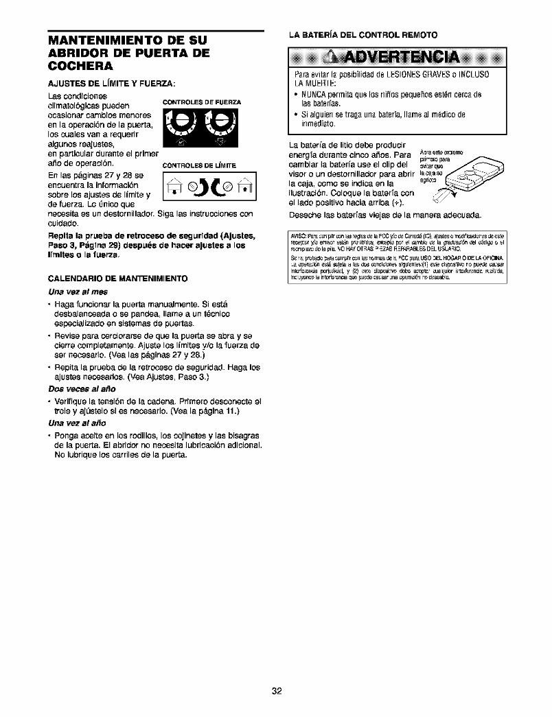
MANTENIMIENTO DE SUABRIDOR DE PUERTA DECOCHERA
AJUSTES DE LfMITE Y FUERZA:
I-ascondicionesclimatol6gicas puedenocasionar cambios menorasen la operaciSn de la puerta,los cuales van a requeriralgunos reajustes,en particular durante el primer
CONTROLESDEFUERZA
ado de operacibn. CONTROLESDEL{MITE
En las p,ginas 27 y 28 se _ (_)_(Dencuentra la informaci6n _u osobre los ajustes de Ifmite yde fuerza, Lo _nico quanecosita as un destornillador. Siga las instrucoiones concuidado.
Replta la prueba de retroceso de segurldad {AJustes,Peso 3, P_gtna 29) despuea de hacer aJuatea a losI[rnltes o la fuerza.
CALENDARIO DE MANTENIMIENTO
Una v_z a! rn_;
• Haga funcionar la puerta manualmente. Si eat&desbalancoada o se pandea, llama a un t6cnicoespecializado en sistemas de puertas.
• Revise para oerciorarse de qua la puerta se abra y secierre completamente. Ajuste los Ifmites y/o la fuerza deser necesafio. (Yea las p&ginas 27 y 28.)
• Repita la prueba de la retrcoeso de seguridad. Haga losajustes necosarios. (Yea Ajustes, Paso 3.)
DOS races al afio
• Verifique la tensiSn de la cadena. Pfimero desconecte eltrois y ajL_stelosi es necosario. (Vea la p_ina 11.)
Una vP.zal a_o
• Ponga acoite en los rodillos, los cojinetas y las bisagrasde la puerta. El abridor no necosita lubricacidn adicional.No lubfique los carriles de la puerta.
LA BATER{A DEL CONTROL REMOTO
ERTErt¢i Paraevit_r la posibilidad de LESIONESGRAVESo INCLUSO/A MUER_E:
• NUNCApermita qua los rlifios pequehos esten cerca delas hater[as.
• Si alguien se traga una baterfa, Ilarneal rn_dico deinrnediato.
La baterfa de litio debe producirenergfa durante cinco a_os. Para A_ eetee_re_
pdmsl__Fparacambiar la baterfa use el clip del _ar quavisor o un destornillador para abfir lacaase
ilustraci6n. Coloque la baterfa conel lado positivo hacia arriba (+).
Deseohe las baterfas viejas de la manera adecoada.
[ AVISO:F,__ _ur_plir_rl I_ _egl_ dela FC6y/_de _rT_ (IO) a]u_tCsOTn_Jifi_ciOTlCSdee_te
r_lpl_zo tie la pila.',0 HAYOT-3AS_EZ_8 I=EPAP_31.E_ D-3.U_L_-31C. //
/
32
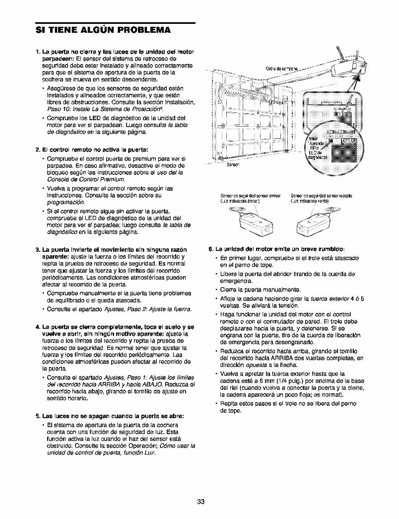
Sl TIENE ALGUN PROBLEMA
1. La puerta no clerra y lee I_ces de la _nldad del motorparpadean: El sensor del sistemade retroceso deseguridaddebe estar instaladoy alineadocorreetamenteparaque el sistemade apertura de la puertade lacocherase mueva en sentidodescendente.
• Aseg0rese de que los sensorosde seguridadest_ninstalados y alineados correetamente, y que est_nlibres de obstrucciones.Consulte la seccibn Instalaci6n,Paso 10: instate La Sistema de Proteosi6fP.
• Compruebe los LED de diagnbstios de la unidad delmotor para ver si parpadean. Luego consulte ta tabtade diagn6stico en la siguiente pbgina.
2. El control remote rio actlva la puerta:
• Compruebe el control puerta de premium para ver siparpadea. En case afirmativo, desactive el modo debloqueo segOn las instrucciones sobre el use de/laConsota de Control Premium.
• Vuelva a programar el control remote segL_n lasinstrucciones. Consulte la seooi6n sobre suprogramaci6n.
• Si el control remote sigue sin activar la puerta,¢ompruebe el LED de diagnbstios de la unidad delmotor para ver si parpadea; luego consulte ta tabla dediagndstico en la siguiente p_Lgina.
(=l_Zrdica¢orav0_J0)
3. La puerta lrtvlerte el rnovlrnlento elrt rtlrtgurta razbrtaparertte: ajuste la fuerza o los ITmitesdel reosrrido yrepita la prueba de retroseso de seguridad. Es normaltener que ajustar la fuerza y los Iimites del recorridoperibdicamente. Las condiciones atmosfbricas puedena1_ectaral recorfido de la puerta.
• Compruebe manualmente si la puerta tiene problemasde equilibrado o si queda atascada.
• Consulte el apertado Ajustes, Paso 2: Ajuste la fuerza.
4. La puerta ee clerra completarnertte, toca el euelo y eevuelve a abrlr, eln rtlngOn motlvo aparertte: aiuste lafuerza o los Iimites del recorrido y repita la prueba deretroceso de seguridad. Es normal tener que ajustar lafuerza y los ITmitos del reosrrido peri6dicamente. Lascondicionos atmosf_ricas pueden a1_eetaral recorrido dela puerta.
• Consulte el apartado Ajustes, Paso 1:Ajuste los t[mitesdel recorrido hacia AFIRtBA y hacia ABAJO. Reduzca elrecorrido hacia abajo, girando el tornillo de ajuste ensentido horatio.
5. Lee ILeceeno se epagan cLeando la puerta se abre:
• El sistema de apertura de la puerta de la ¢ocheracuenta con una funcibn de seguridad de luz. Estafuncibn activa la luz cuando el haz del sensor estbobstruido. Consulte la seccibn Operacibn; C6mo usar launidad de control de puerta: funci6n Luz.
6. La unldad del motor ernlte urt breve zurnbldo:
• En primer lugar,compruebe si el troleestb atascadoen el perno de tope.
• Ubere la puerta del abridor tirando de la cuerda deemergencia.
• Cierre la puerta manualmente.
• A1_lojela ¢adena haciendo girar la tuerca exterior4 b 5vueltas. Se aliviara la tensibn.
• Haga funcionar la unidad del motorcon el controlremote o con el ¢onmutador de pared. El trole debedesplazarse hacia la puerta, y detenerse. Si seengrana con la puerta, tire de la cuerda de liberaci6nde emergencia para desengranarlo.
• Reduzca el reosrrido hacia arriba, girando el tornillodel recorrido hacia ARRIBA dos vueltas completas, endirecci6n opuesta a la flecha.
• Vuelva a apretar la tuerca exterior hasta que lacadena est_ a 6 mm ('i/4 pulg.) per encima de la basedel riel (cuando vuelva a coneetar la puerta y la cierre,la cadena aparecera un pete floja; es normal).
• Repita estos pasos si el trole no se libera del pernode tope.
33
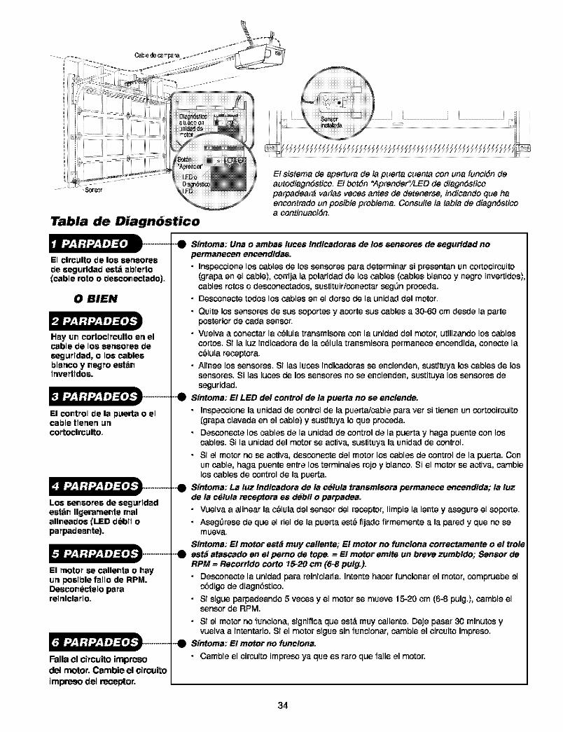
Tabla de Diagn6stico
El $ietema de ape_ra de la puerta cuenta con una funci6n deautodiagndetico. EI bot6n "Aprendef'iLED de diagndeticoparpadearg variae veces antes de detenerse, indicando clue haencontrado un posible problema. Coneulte ta _abla de diagn6sticoa continuaci6n.
El clrc_lto de los eeneoree
de eegurldad _ ablerto(cable roto o deeconectedo),
0 BIEN
Hay un cortoclrculto en elcable be los sensores beseg_rlded, o los cablesblenco y negro eet_nlnvertldoe.
El control de la puerta o elcable tlenen urtcortocln:ulto,
Los seneoree de eegurldadeet_n Ilgeramente realallneadoe (LED debll oparpadeante).
El motor se callenta o hayun poelble fallo de RPM.Deeconectelo parerelnlclarlo,
Falla el circuito innpreeod_l motor, Cannbieel circuitoirnpr_so del receptor,
Sfntoma: Una o ambas tuces Indlcadoras de los sensor.s de segurldad nopermane_en en_andldas.• Inspecoione los cablesde los sensoresparadeterminar si presentanuncortocircuito
(grapa en el cable), corrija la polaridad de los cables (cables blanco y negro invertidos),cables rotos o desconectados, sustituir/conectar seg0n procoda.
• Desconecte todos los cables en el dorso de la unidad del motor.
• Quitelossensores de sus soportes y acortesus cablesa 30-60 cm desde la parteposterior de cada sensor.
• Vuelva a conectar la c_lula transmisora con la unidad del motor, utilizando los cablescortos.Si la luz indicadorade la c_lula transmisora permanece encendida, conecte lac_lula receptora.
• Alinee los sensores. Si las lucos indicadorasse encienden, sustituya los cables de lossensores. Si las luces de los sensores no se encienden, sustituya los sensores deseguridad.
Sfntoma: E! LED del control de ta puerta no se enclende.
• Inspecoionela unidadde controlde la puerta/cableparaver si tienen uncortcoircuito(grapa clavadaen el cable)y sustituyaIoque proceda.
• Desconectelos cablesde la unidad de control de la puerta y haga puente con loscables. Si la unidad del motor se activa, sustituya la unidad de control.
• Si el motor no se activa, desconecte del motor los cables de control de la puerta. Conun cable, haga puente entre los terminales rojo y blanco. Si el motor se activa, cambielos cables de control de la puerta.
..._ Sfntoma: La tuz Indlcadora de la celuta transmlsora permaneco en_andlda; ta luzde la c_tuta recoptora es deb!! o parpadea.• Vuelva a alinear la c_luladel sensordel receptor, limpie la lente y asegure el soporte.
• AsegOresede que el riel de la puerta est_ fijado firmemente a la pared y que no semueva.
Sfntoma: E! motor est_ muy callente; El motor no funclona cort_ctamento o e! troteeet_ ataecado en e! perno de tope. -- El motor emlte un bt_ve zumbldo; Sensor deRPM -- Recorrldo corto 15-20 cm (6-8 putg_).
• Desconecte la unidad para reiniciarla. Intente hacor funcionar el motor, compruebe elc6digo de diagn6stico.
• Si sigue parpadeando 5 vecos y el motor se mueve 15-20 cm (6-8 pulg.l, cambie elsensor de RPM.
• Si el motor no funciona, significa que est,. muy caliente. Deje pasar 30 minutos yvuelva a intentarlo. Si el motor sigue sin funcionar, cambie el circuito impreso.
-0 Sfntoma: E! motor no func!ona.
• Cambie el circuito impreso ya que es raro que falle el motor.
34
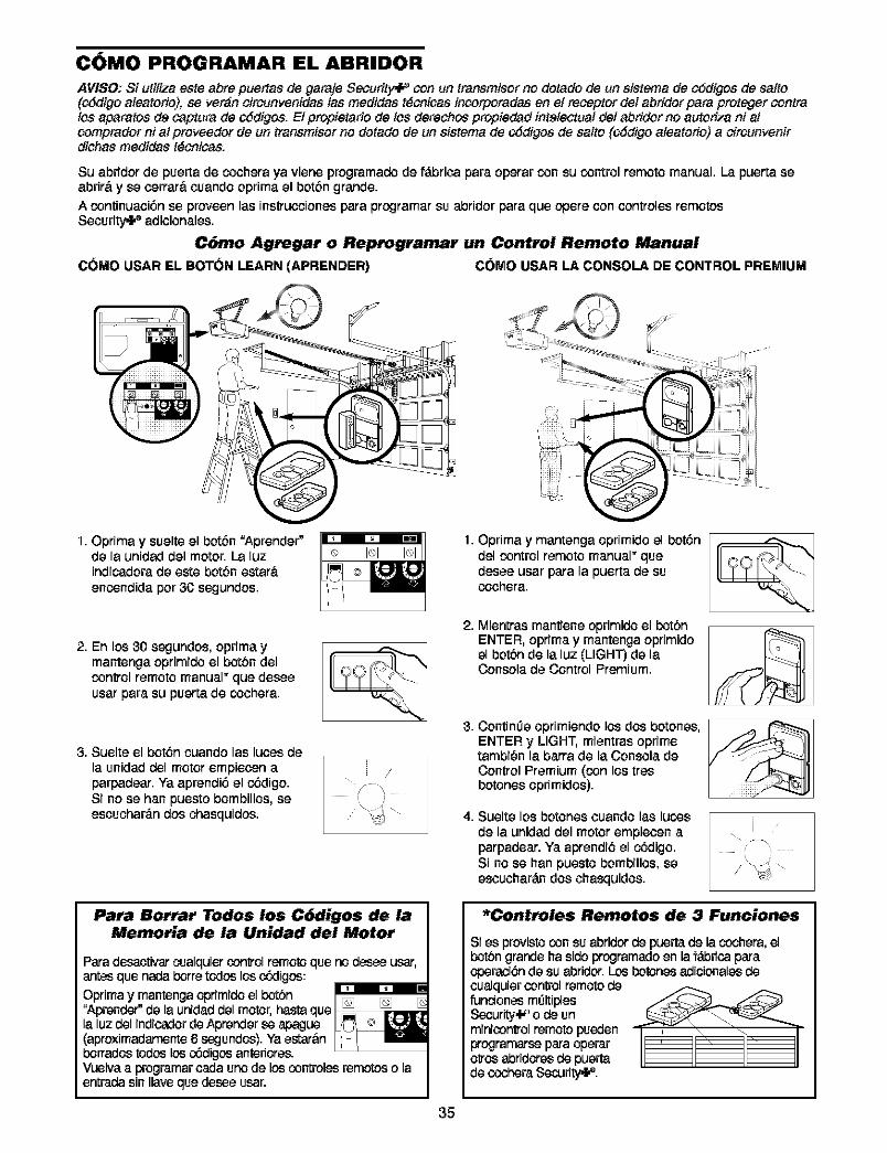
COMO PROGRAMAR EL ABRIDOR
AVISO; Si utitiza oste abre puertas de garaje Security_ con un transmisor no dorado de un sistema de oSdigee de satto(¢Sdigo aleetorio), ee ver_n circunvenidas #asmedidas t_cnicas incorporedas en el receptor de/abridor para proteger contralos aparafos de ceptura de cSdigos. EI propietario de los derechos propiedad intetectual de/abridor no autoriza ni atcomprador ni a#proveedor de un transmisor no dotado de un sistema de cSdigos de salto {cSdigo ateatofio) a cireunvenirdichas medidas t_coice&
Su abridorde puerta de cochera ya viene programado de f_.bricapara operarcon su control remoto manual. La puerta eeabrir& y ee eerrar&cuando oprimael bot6n grands.A continuaci6n ee proveen las instrucoionespara programar su abfidor para que opere con controles remotosSecurity_l," adicionalee.
C6mo Agrogar o Reprogramar un Control Remoto Manual
C(}MO USAR EL BOT(}N LEARN (APRENDER) cor_o USAR LA CONSOLA DE CONTROL PREMIUM
I. Optima y suelteel bot6n "Aprender"de la unidad del motor.La luzindicadora de este bot6n estarQencondidapor 30 eegundes.
[]
ii /'
: i
1. Oprima y mantenga oprimJdoel bot6ndel control remoto manual" quedeeee usar para la puerta de sucochera.
2. En los 30 segundes, oprimaymantengaoprimidoel botbn delcontrol remoto manual" que deeeeueer para su puerta de cochera.
3. Suelte el bot6n cuando les luees de
la unidad del motor empieeen aparpadeer. Ya aprendi6 el c6digo.Si no ee ban puesto bombillee, eeescuchar#.n dos chesquides.
Para Borrar Todos los C6digos de laMemoria de la Unidad del Motor
Para desactivar cualquiercor_ol remoto que no desee ueer,antes que nada borre todes los c,Sdiges:
Oprima y mantonga oprimido el botbn"Aprender" de la unidad del motor, hesta que []la luz del indicador de Aprender ee apague(aproximadamente 6 eegundos). Ya estar&nborrados todes los c_diges antedores.Vuelva a programar cada uno de los controles remc_os o laentrada sin Ilave que deese usar.
2,
3,
4,
Mientras mantiene oprimido el bot6nENTER, optima y mantenga opfimidoel bot6n de la luz (LIGHT) de laConeela de Control Premium.
Contim3e opfimiendo los dos botoneeENTER y LIGHT, mientres oprimetambi_n la barra de la Consola deControl Premium (con los treebotones oprimidee).
Sueltelos botones cuandolab lucosde la unidad del motor empieeen aparpadear. Ya aprendi6 el c6digo.Si no ee han puesto bombillos, eeescuchar#.ndos chesquidee.
/'
{\ i
*Controles Remotos de 3 Funciones
SI ee provisto con su abridor de puerta de la ccohera, elbot6n grands ha sido programado en la f&biica paraoperaci6n de su abridor. Los Ix)tones adicionalee decualquiercontrol remotodefundones m{31tipleeSecurity,l.#o de unminicor_ol remotopuedenprogramareeparaoperaro{_osabfidoreede puertade ccoheraSecudty,P.
35
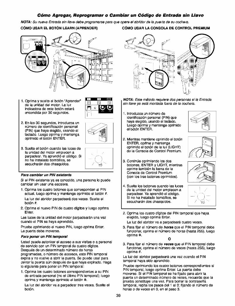
C6mo Agregar, Reprogramar o Cambiar un C6digo de Entrada sin Llave
NOTA: Su nueva Entrada sin ltave debe programarse para que opere el abridor de la puerta de su ¢'ochera.
COMO USAR EL BOTON LEARN (APRENDER) COMO USAR LA CONSOLA DE CONTROL PREMIUM
1. Oprima y suelte el bot6n "Aprender"de la unidad del motor. La luzindioadora de este bot6n estate.enoendida por 30 segundos.
2. En los 30 segundos, intraduzca unnL_mera de identificacibn personal(PIN) que haya elegido, usando elteolado. Luego oprima y mantengaoprimido el botbn ENTER.
3. Suelte el bot6n ouando las lucos de
la unidad del motor empiecon aparpadear. Ya aprendi6 el c6digo. Sino ha instalado bombillos, seescuohar&n dos ohasquidos.
/
Para carnblar un PiN ex!$tente
Si el PiN exi_ente ya es Conocido,una persona Io puedecambiar sin usar una escalera.
1. Oprima los cuatro botones que correspondan al PINactual, luego optima y mantenga oprimido el bot6n #.
La luz del abridor parpadear& dos vecos. Suelte elbot6n #.
2. Oprima el nuevo PIN de cuatro dfgitos y luego oprimaEnter.
Las luoesde la unidad del motorparpadear_.nunavezcuandoel PIN se haya aprendido.Pruebeoprimiendo el nuevo PIN, luego oprima Enter.La puerta debe moverse.
Para porter un PiN temporal
tJstedpuede autorizar el acoeso a sus visitaso a personalde sewioio con un PIN temporal de cuatrodfgitos.Despu_s de un determinado nL_merode horasprogramadas, o nL_merode acoesos, este PIN temporalexpira y no vuelve a abrir la puerta. Se puede usar paracerrar la puerta alandespu_s de que haya expirado. HagaIo siguiente para poner un PINtemporal:1. Oprima los cuatro botones oorrespondientes a su PIN
de entrada personal (no el 01timoPIN temporal); luegooptimay mantenga oprimidoel botbn _.
La luz del abridorva a parpadear tres vecos. Suelteelbot6n.
NOTA: Este m#todo requiere dos personas si ta Entradasin ltave ya est_ mon_ada fuera de la ¢'ochera.
I. Introduzca un n0mero deidentificaci6n personal (PIN) quehaya elegido, usando el teclado.Luego oprima y mantenga oprimidoel bot6n ENTER.
2. Mientras mantiene opfimido el bot6nENTER, oprima y mantengaoprimido el bot6n de la luz (LIGHT)de la Consola de Control Premium.
3. Contin0e oprimiendo los dosbotones, ENTER y LIGHT, mientrasoprime tambi_n la barra de laConsola de Control Premium(con los tras botones oprimidos).
z_.Suelte los botones cuando las lutesde la unidad del motor empiecon aparpadear. Ya aprandi6 el obdigo.Si no ha instalado bombillos, seescuchar&n dos chasquidos.
i//
36
2. Optima losouatrodfgitos del PIN temporal que hayaelegido, luego oprima Enter.La luz del abridor va a parpadear& cuatro vecos.
3. Para fijar el n0mera de horas que el PIN temporal debefuncionar, oprima el nL_merode horas (basra 255), luegooprima _.
O
3. Para fijar el nL_merode vecesque el PIN temporal debefuncionar, oprima el nL_merode veces (basra 255), luegooprima #.
La luz del abridor parpadear& una vez coando el PINtemporal haya sido aprendido.Pruebe oprimiendo los coatro botones oorrespondientes alPIN temporal, luego optima Enter. La puerta debemoverse. Si el PIN temporal se ha fijado para abfir lapuerta un determinado nOmerode vecos, recuerde que laprueba constituye una vez. Para borrar la contrasefiatemporal, repita los pasos del "i al 3; fijando el nL_merodehoras o de vecosen 0, en el paso 3.
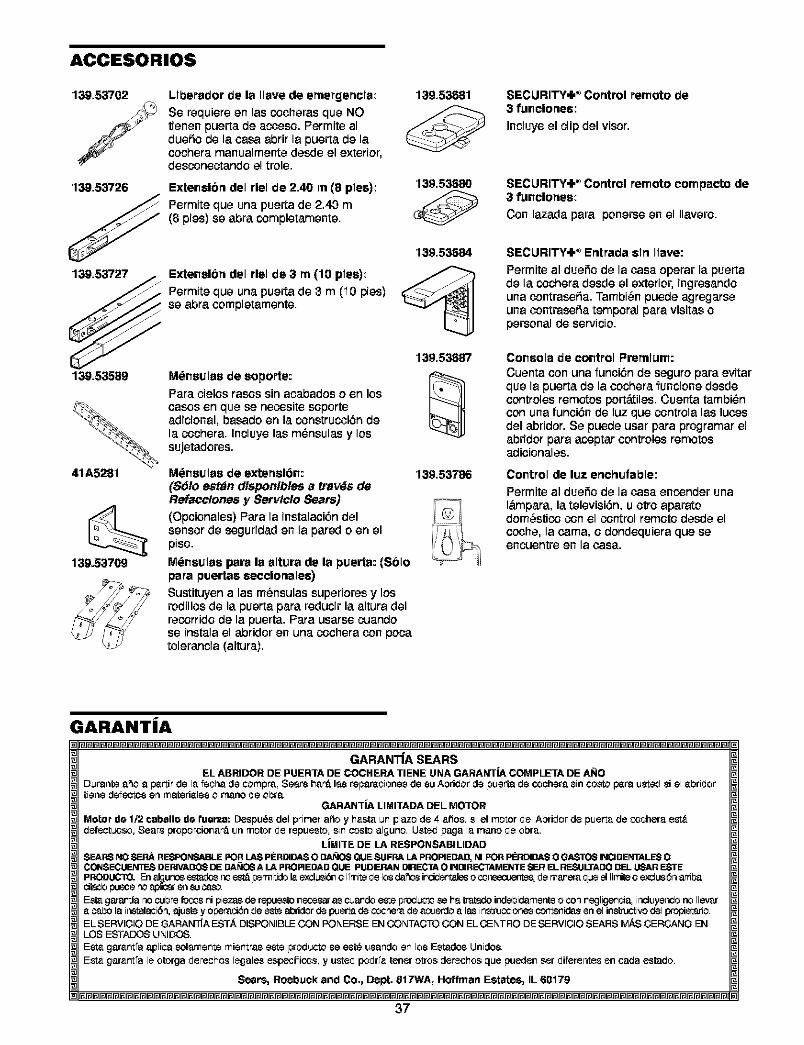
ACCESORIOS
139,53702
139,53726
Llberador de la Ileve de ernergencla:Se requiere en las cocheras que NOtienen puerta de acoeso. Permite alduefio de la casa abrir la puerta de lacechera manualmente deede el exterier,
desconeetando el trele.
Extenelbrtdel rlel de 2.40 rn (8 pies):Permite que una puerta de 2.40 m(Bpies) se abra completamente.
139,53681
139,53680
139,53684
139,53727 Extenelbrtdel rlel de 3 rn(10 plee):
_ Permiteque una puertade 3 m (iOpies)
Be abraoompletamente.
139,53687
139.53589 M_neulae de eoporte:Pare cielosrases sinacabadoso en losoases en que se necositesoporteadicional, basado en la construcoi6ndela cochera. Incluyelas m_nsulas y lossujetedores.
41A5281 M6neulae de extertel6n: 139,53786($61o estan dlsponlbles a travd$ deReface!ones y Servlclo Sears)(Opoionales)Pare la instalaoi6n delsensor de segurided en la pared o en elpiso.
M_nsulas papala altura de la puerta: (Solopare puertae eecclonalee)Sustituyen alas m_nsulassuperioresy losrodillosde la puertapare reducirla altura delrecorridode la puerta.Para usarse cuandose instalael abridor en una cocheracon pocatolerancia(altura).
139.53709
SECURITY,I ,_ Corttrol remote de3 funclortee:
Incluye el clip del visor.
SECURITY,I ,_ Corttrol remote compacto de3 funclortee:
Con lazeda para ponerseen el Ilavere.
SECURITY,I ,_ Erttrada elrt Ilave:
Permite al duefio de la case operar la puertade la cochera desde el exterior, ingresandouna contrasefia. Tambi_n puede agregarseuna contrasefia temporal pare visitas opersonal de servicio.
Console de control Premium:Cuenta con una funoi_;nde seguropare evitarque la puerta de la oocherafuncione desdecontroles remotos port,.tiles. Cuenta tambi_ncon una funci6n de luz que controla las lutesdel abridor. Se puede usar para programar elabridor pare acoptar controles remotosadicionales.
Control de luz ertchufable:Permiteal duefio de la case encender unalampara, la televisi6n,u otto aparatodom_sticoconel control remotedeede elccohe, la cama, o dondequiera que seencuentre en la case.
GARANT|A
GARAN'iiA SEARSEL ABRIDOR DE PUER'rA DE COCHERA TIENE UNA GARANT|A COMPLETA DE ANO
D_ranto a_o a I_'trIirde le feohe de compre, Seer_ hee_ I_s repareoiones de su Abric_orde puerta de cochera sin costo I_'trauste_Jsi el ebri_Jortiene d_fectos en materieles o mane _Jeobra.
GARANT|A LIMll'ADA DEL MOTOR
Motor de 1/2 cabello de reeve: Despu6s del primer erie y heata un plazo de 4 afros, si el motor _JelAbri_Jorde puerIe de coohere est#,c_efeotuoso,Sears proporoionae_ un motor _Jerepuesto, sin ¢osto alguno. USto_page le mane _Jeobre.
LiMI'rE DE LA RESPONSABILIDADSEARS NO SEF_ RESFONSABLE POR LAS PERDIDAS O DA_ilOS Q_JESUFRA LA PROPIEDAD, NI POR PBIDIDAS O GASTOS INCIDENTALES OCOINSECUEN3T=.SDE RIVADOS DE DAt'_CJ6A LA PRO RE DAD QUE PUDEP.AJNDIRECI_ O INDIR ECTAMENTE Sr_R EL RESULTADO DEL _R ESTE
dt_o pu_e r'_ ap _r erl _J _.
Est_ g_a_r_{a r_oCubn_ _o_._s ni piezas de r_JeSto n_:es_rias C_SndO _ p no_L_.'_Ose he tn_d_o indebiden_ente o corl negligen_ia, ir_luy_r_o no llevara _o la ir'_lalaci6n,ajustey o_e_:i_n de este _d3ridorde l_S_a de C_c_e_ de a_._srdoa las inst_ccionescor_nidE_sen el instn_ti_ del pmf_rio.EL $ERVIOIO DE GARAN_'A EST,&, DISPONIBLE CON PONERSE EN CO NTACTO CON EL CENTRe DE SERVIOIO SEARS i_$ OEROANO EN
LOS ES3-ADOS UNIDO$.
Esta garant'e eplica solemente mientres este proc_ucto se est_ usande en los Estados Unidos.Esta garant'e le otorge _Jereohos lecjales espec|linos, y uste_Jpo_Jr'a toner oIros detaches que pueden ser _Jiferer_esen cede estac_o.
Sears, Roebuck and Co., Dept. 81T-NA, Ho_fman Estates, IL 60179
37
Your Home
For repair-in your home-of all major brand appliances,lawn and garden equipment, or heating and cooling systems,
no matter who made it, no matter who sold it!
For the replacement parts, accessories andowner's manuals that you need to do-it-yourself.
For Sears professional installation of home appliancesand items like garage door openers and water heaters.
1-800-4-MY-HOME ® (1-800-469-4663)Call anytime, day or night (U.S.A. and Canada)
www.sears.com www.sears.ca
Our Home
For repair of carry-in items like vacuums, lawn equipment,and electronics, call or go on-line for the location of your nearest
Sears Parts & Repair Center.
1-800-488-1222Call anytime, day or night (U.S.A. only)
www.sears.com
To purchase a protection agreement (U.S.A.)or maintenance agreement (Canada) on a produc_ serviced by Sears:
1-800-827-6655 (U.S.A.) 1-800-361-6665 (Canada)
Para pedir servicio de reparaci6na domicilio, y para ordenar piezas:
1-888-SU-HOGAR sM
(1-888-784-6427)
Au Canada pour service en frangais:
1-800-LE-FOYER M°
(1-800-533-6937)www.sears.oa
_') Registered Trademt_rk l _" Trademark / _" Service Mark o'f 8ears, RoebuoK amd Co.® Marca Registrada ! _" M_rc_ de F_brica ! _ M_rc_ de 8ervicio de Sears, Roeb_lck arid Co.
Marque (is commerce/"" MarQue d6p<_s_e (is Sears, Roebuck _n(J Co.© 200,1 Sears, Roeb_lck arid Co.
Primte_ imMexic_
Recommended