DEFENDER Td5CONVERSION MANUAL
01.03.06 © Land Rover Version 1.0

Land Rover Defender Td5 Conversion Manual 01.03.06 © Land Rover Version 1.0
1. INTRODUCTION 3
2. COMMERCIAL AND LEGAL 4
Terminology 4
3. VEHICLE WEIGHTS 6
3.1 EEC Kerb Weights 6
(unladen + full fuel + 75kg driver – no options fitted) 6
3.2 MANDATORY MINIMUM EEC Kerb Weights 6
(unladen + full fuel + 75kg driver – no options fitted) 6
3.3 Gross Vehicle Weights (GVW) 7
3.4 Centre of Gravity Heights 7
3.4.1 Base Vehicle Centre of Gravity Heights 7
3.4.2 Maximum Centre of Gravity Height at GVW 7
3.5 Weights of Optional Extras 8
3.6 Predicting Vehicle Weights/Centre of Gravity 8
4. VEHICLE DIMENSIONS 9
4.1 Maximum Overall Dimensions 9
4.2 Vehicle Bodywork 10
4.2.1 Defender – Interface Drawings 10
5. CHASSIS, SUB FRAMES AND BODY MOUNTING 12
5.1 Chassis Modifications 12
5.2 Operating Clearances 12
5.3 Mounting to the Chassis 12
5.4 Stabiliser Legs 13
5.5 Securing of Loose Equipment 14
6. TECHNICAL GUIDELINES 15
6.1 General Vehicle Conversion Do’s and Don’ts: 15
6.2 Vehicle Design Guidelines 16
6.3 Safety 16
6.4 Vehicle Function and Duty Cycles 17
6.4.1 General 17
6.4.2 Electrical Duty Cycle Guidelines: 17
6.4.3 Conversion Effect on Specific Performance Aspects of the Vehicle 17
6.5 Vehicle Durability and Reliability 20
6.6 Vehicle Quality and Refinement 21
6.7 Vehicle Serviceability 21
6.8 Operator’s Instructions and Parts Listings 22
6.9 Labels, Guards and Gauges 23
6.10 Vehicle Cost of Ownership 24
6.11 End of Life Vehicle Directive – Material Restrictions and Recycleability 24
7. WORKING PRACTICES 26
7.1 General 26
7.1.1 Electrical Circuitry (General) 26
7.1.2 Switches and Relays 26
7.1.3 Electromagnetic Compatibility (EMC), Interference Suppression
and Legal 26
7.1.4 Lighting - Legal 27
7.1.5 Wires and Cables 27
7.1.6 Connectors 27
7.1.7 Routing of Wires and Cables 28
7.1.8 Precautions when Welding 28
7.2 Paint and Protection 28
7.3 Health and Safety 28
7.4 Pipework 29
7.4.1 Materials 29
7.4.2 Routing 29
7.4.3 Brake Pipes 29
7.5 Welding 29
7.5.1 Welding to the Chassis 29
7.5.2 Protection 29
8. APPENDICES 30
8.1 Defender 110 Cab - Interface Drawing 30
8.2 Defender 130 Chassis Cab - Interface Drawing 31
8.3 Defender 130 Double Cab - Interface Drawing 32
CONTENTS

3
CONTENTS
Land Rover Defender Td5 Conversion Manual 01.03.06 © Land Rover Version 1.0
This manual has been produced to support the development of your own
conversions and modifications and contains data for 110" and 130" Land Rover
Defenders with Td5 Diesel engine. This manual has been designed for conversions
and modifications carried out on vehicles for use in the UK market only.
It must be emphasised that any change to the basic vehicle, which does not
meet the enclosed guideline standards, may severely inhibit the ability of
the vehicle to perform its function. Mechanical failures, structural failure,
component unreliability or vehicle instability will lead to customer dissatisfaction.
Appropriate design and application of body, equipment and/or accessories is
key to ensuring that customer satisfaction is not adversely affected.
This manual has been designed to provide an easy to use reference file with
an index and is cross linked to the data charts and drawings showing weights,
permissible loads and useful dimensions. Section 2 is on Commercial and Legal
advice. Sections 3 to 7 inclusive, are specific to the vehicle and all contain further
useful information and some unique warnings which must be observed.
The illustrations, descriptions and specifications in this manual were correct
as at January 2006. However, Land Rover’s policy is one of continuous product
development and Land Rover reserves the right to amend the information
contained in this manual at any time. If in doubt or for the latest information,
always consult your Land Rover dealer.
This manual is intended for use by technically competent Vehicle Converters /
Automotive Body Builders / Coachbuilders only. This document should be read in
conjunction with the Land Rover Defender Td5 handbook which is available online
at www.ownerinfo.landrover.com
This manual is intended to cover the application of ‘bolt on’ conversions only.
The information contained in this manual does not grant or imply Land Rover
approval and all vehicle or component alterations remain the responsibility
of the converter.
It is the responsibility of the converter to ensure that the completed
vehicle meets all relevant regulations. For example, safety harness anchorages,
weights, and territorial legal requirements etc.
It must be remembered that conversion as well as certain modifications
may invalidate legal approvals and that application for re-certification may
be necessary.
1. INTRODUCTION
CONTENTS
Terminology:
‘Converter’: refers to any Body Builder, converter, coachbuilder and/or
re-seller third party changing the vehicle by altering the body and adding or
modifying any equipment not originally specified and/or supplied by Land Rover.
‘Unique component’ or similar wording refers to non-Land Rover specified
or after market fitment and is not covered by Land Rover warranty.
‘Equipment manufacturer and/or supplier’ or similar wording refers to
non-Land Rover specified or aftermarket fitment and is not covered by
Land Rover warranty.
Warranty on Land Rover Vehicles:
Refer to Warranty Benefits Documents supplied with vehicle for details
of standard Land Rover warranties.
The Converter should warrant its design, materials and construction for
a period at least equal to the applicable Land Rover warranty.
The Converter must ensure that any alteration made to a Land Rover
vehicle or component does not reduce the safety, function, or durability
of the vehicle or components.
The Converter shall be solely responsible for any damage resulting from any
alteration made by the Converter or any of its agents, to a Land Rover vehicle
or component.
Land Rover will not accept claims by any third party for any cost or loss
(including any consequential damages) arising from work performed by a
converter, unless Land Rover has given its prior written consent to and
acceptance of such liability.
General Product Safety Requirement:
The Converter shall ensure that any vehicle it places on the market complies with
the European General Product Safety Directive 2001/95/EC, the General Product
Safety (GPS) Regulations 2005 and any other related implementing legislation
(in each case, as amended from time to time).
The Converter shall also ensure that any alteration it makes to a Land Rover
vehicle or component does not reduce its compliance with the European General
Product Safety Directive, the General Product Safety (GPS) Regulations 2005
and any such related implementing legislation.
NOTE: The Converter must record in writing all modifications and/or alterations
to the vehicle in supplementary descriptive literature, and include such written
record with the owner’s vehicle documentation.
The Converter shall release Land Rover from all liability for damages resulting from:
• Any failure to comply with the directives and warnings contained or referred to
in this manual.
• Any faulty design, production, installation, assembly or alteration not originally
specified by Land Rover.
• Any failure to comply with the basic ‘fit for purpose’ principles inherent in the
original product.
2. COMMERCIAL AND LEGAL
4
Land Rover Defender Td5 Conversion Manual 01.03.06 © Land Rover Version 1.0

CONTENTS
Product Liability:
The Converter shall be liable for any product liability (whether for death,
personal injury, or property damage) arising from any alteration to a Land Rover
vehicle or component made by the Converter or any of its agents. Land Rover
shall not be liable for any such liability (except as provided by law).
The Converter (or equipment manufacturer) is liable for the:-
• Operational reliability and road-worthiness of the vehicle to its original intent.
• Operational reliability and road-worthiness of any component or conversion,
not listed in the original Land Rover manuals.
• Operational reliability and road-worthiness of the vehicle as a whole
(eg. the body changes and/or additional equipment must not have a negative
effect on the driving, braking or steering characteristics of the vehicle).
• Subsequent damage resulting from the conversion or attachment and
installation of unique components, including unique electrical or electronic
systems.
• Functional safety and freedom of movement of all moving parts (eg. axles,
springs, propeller shafts, steering mechanisms, brake and transmission
linkage, retarders, etc.).
Type Approval:
The Converter must ensure that the completed vehicle conversion and/or
modifications comply in all respects with the legal regulations for the country
in which the vehicle is sold. Such legislation which shall include but without
limitation National Type Approval and satisfaction of the Road Vehicles
(Construction & Use) Regulations 1986 (as amended), where applicable, are hence
the responsibility of the Converter.
Legal and Vehicle Type Approval:
• All components embodied on Land Rover vehicles have National Type Approval.
• Land Rover vehicles have National Type Approval for the intended
marketing territories.
Exception - Incomplete vehicles such as Chassis Cabs may require further
approval when completed by the Converter.
• The Defender has National Type Approval for many territories, although the
variants listed in this manual are not necessarily released in all territories.
• Significant changes to the vehicle may affect its legal compliance. Strict
adherence to the original design intent for brakes, weight distribution, lighting,
occupant safety and hazardous materials compliance in particular is mandatory.
Alternative Type Approval: the Converter must observe any legal and/or
regulatory requirements. If significant changes are made, the Converter
must negotiate Single Vehicle Approval with the relevant authority.
• Any changes to the vehicle operating conditions must be advised to
the customer.
Legal Obligations and Liabilities:
The Converter should consult with its legal advisor on any questions concerning
its legal obligations and liabilities.
5
Land Rover Defender Td5 Conversion Manual 01.03.06 © Land Rover Version 1.0
6
CONTENTS
Land Rover Defender Td5 Conversion Manual 01.03.06 © Land Rover Version 1.0
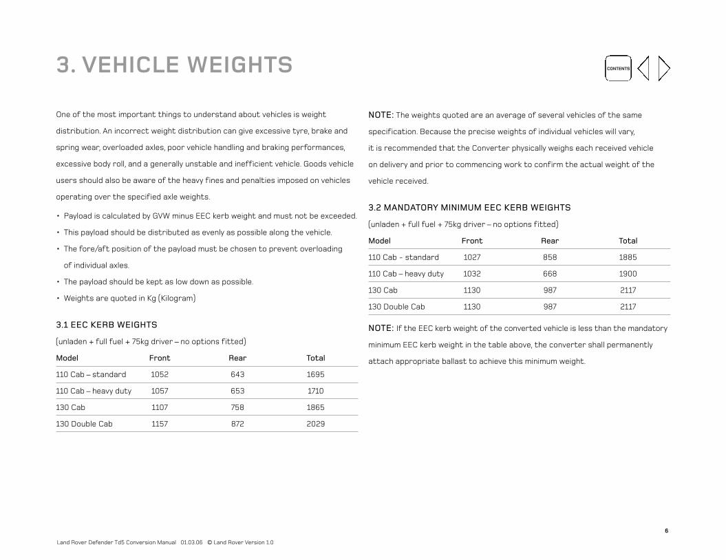
One of the most important things to understand about vehicles is weight
distribution. An incorrect weight distribution can give excessive tyre, brake and
spring wear, overloaded axles, poor vehicle handling and braking performances,
excessive body roll, and a generally unstable and inefficient vehicle. Goods vehicle
users should also be aware of the heavy fines and penalties imposed on vehicles
operating over the specified axle weights.
• Payload is calculated by GVW minus EEC kerb weight and must not be exceeded.
• This payload should be distributed as evenly as possible along the vehicle.
• The fore/aft position of the payload must be chosen to prevent overloading
of individual axles.
• The payload should be kept as low down as possible.
• Weights are quoted in Kg (Kilogram)
3.1 EEC KERB WEIGHTS
(unladen + full fuel + 75kg driver – no options fitted)
Model Front Rear Total
110 Cab – standard 1052 643 1695
110 Cab – heavy duty 1057 653 1710
130 Cab 1107 758 1865
130 Double Cab 1157 872 2029
NOTE: The weights quoted are an average of several vehicles of the same
specification. Because the precise weights of individual vehicles will vary,
it is recommended that the Converter physically weighs each received vehicle
on delivery and prior to commencing work to confirm the actual weight of the
vehicle received.
3.2 MANDATORY MINIMUM EEC KERB WEIGHTS
(unladen + full fuel + 75kg driver – no options fitted)
Model Front Rear Total
110 Cab - standard 1027 858 1885
110 Cab – heavy duty 1032 668 1900
130 Cab 1130 987 2117
130 Double Cab 1130 987 2117
NOTE: If the EEC kerb weight of the converted vehicle is less than the mandatory
minimum EEC kerb weight in the table above, the converter shall permanently
attach appropriate ballast to achieve this minimum weight.
3. VEHICLE WEIGHTS

7
CONTENTS
Land Rover Defender Td5 Conversion Manual 01.03.06 © Land Rover Version 1.0
3.3 GROSS VEHICLE WEIGHTS (GVW)
Model Front Rear Total
110 Cab - standard 1200 1850 3050
110 Cab – heavy duty 1580 2200 3500
130 Cab 1580 2200 3500
130 Double Cab 1580 2200 3500
3.4 CENTRE OF GRAVITY HEIGHTS
3.4.1 BASE VEHICLE CENTRE OF GRAVITY HEIGHTS
Approximate centre of gravity heights for these base vehicle specifications in the
EEC kerb weight condition (ie unladen + full fuel + 75Kg driver; no options
fitted) is as below:
Vehicle Body type Tyre size C of G height
above ground
110 standard Cab 7.50 R16 665mm
110 heavy duty Cab 7.50 R16 665mm
130 Cab 7.50 R16 665mm
130 Double Cab 7.50 R16 667mm
3.4.2 MAXIMUM CENTRE OF GRAVITY HEIGHT AT GVW
The following figures are the maximum height of the vehicle's centre of gravity
above ground level and must not be exceeded. These figures relate approximately
to a lateral tilt angle of 35 degrees (the British Ministry of Defence acceptance
standard for this class of vehicle).
Vehicle Body type Tyre size C of G height
above ground
110 standard Cab 7.50 R16 980mm
110 heavy duty Cab 7.50 R16 1042mm
130 Cab 7.50 R16 1042mm
130 Double Cab 7.50 R16 1042mm
These figures are subject to change. On some vehicles, e.g. lighting towers,
hydraulic platforms etc, the C of G may be very high but only when the vehicle
is in a stationary operating role. This is allowable providing that the C of G is
within the specified limits when the vehicle is in the travelling mode. In order to
retain stability whilst in operation these vehicles may require stabiliser legs
to prevent excessive roll and possible overturning. The positions of these legs
will need to be determined by the Converter for individual applications.

8
CONTENTS
Land Rover Defender Td5 Conversion Manual 01.03.06 © Land Rover Version 1.0
3.5 WEIGHTS OF OPTIONAL EXTRAS
Approximate weights of winches, spare wheels, roof racks and most other
Land Rover accessories may be obtained from an authorised dealer.
3.6 PREDICTING VEHICLE WEIGHTS/CENTRE OF GRAVITY
It is important that a check on vehicle weights and centre of gravity height
is done before any conversion work is started.
Step 1 Take EEC kerb weight, axle weights and C of G height from charts for
relevant base vehicle.
Step 2 Determine weights and positions of all parts added/taken away from
the base vehicle.
Step 3 Calculate new axle weights.
Step 4 Calculate new centre of gravity height.
If steps 3 and 4 produce figures that are outside the design maxima already
stated then the weight must be re-positioned/reduced and the calculations
repeated until satisfactory results are achieved. It is obviously much easier to do
this on paper than on a completed conversion! As well as simply not exceeding the
design maxima several other factors need to be understood.
• Weight distribution too far forward can lead to vehicle understeer.
• Front axle weight must be maintained above 900 kg otherwise steering control
is adversely affected.
• If the weight is distributed too far rearwards then the vehicle can tend
to oversteer.
NOTE: The solution to these problems is to distribute the load as low down and
as evenly as possible.
Vibration of attached structures should not adversely affect vehicle control.
CONTENTS4. VEHICLE DIMENSIONS
The limits on vehicle dimensions apply to converters fitting alternative
bodywork onto a Defender and making alterations that will affect the vehicle’s
ground clearance or approach and departure angles. Any increase in vehicle
dimensions can lead to possible poor weight distribution, unacceptable
off-road performance, poor visibility, excessive wind resistance and instability
in high winds.
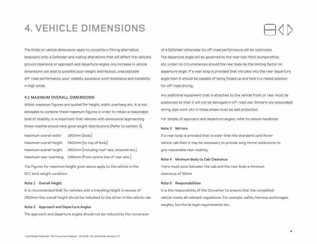
4.1 MAXIMUM OVERALL DIMENSIONS
Whilst maximum figures are quoted for height, width, overhang etc. it is not
advisable to combine these maximum figures in order to retain a reasonable
level of stability. It is important that vehicles with dimensions approaching
these maxima should have good weight distributions (Refer to section 3).
Maximum overall width 1950mm (body)
Maximum overall height 2400mm (to top of body)
Maximum overall height 2800mm (including roof rack, beacons etc.)
Maximum rear overhang 1384mm (from centre line of rear axle.)
The figures for maximum height given above apply to the vehicle in the
EEC kerb weight condition.
Note 1 Overall Height
It is recommended that for vehicles with a travelling height in excess of
2800mm the overall height should be indicated to the driver in the vehicle cab.
Note 2 Approach and Departure Angles
The approach and departure angles should not be reduced by the conversion
of a Defender otherwise its off-road performance will be restricted.
The departure angle will be governed by the rear tow hitch, bumperettes,
etc. Under no circumstances should the rear body be the limiting factor on
departure angle. If a rear step is provided that intrudes into the rear departure
angle then it should be capable of being folded up and held in a raised position
for off-road driving.
Any additional equipment that is attached to the vehicle front or rear must be
positioned so that it will not be damaged in off-road use. Similarly any associated
wiring, pipe work, etc in these areas must be well protected.
For details of approach and departure angles, refer to vehicle handbook.
Note 3 Mirrors
If a rear body is provided that is wider than the standard Land Rover
vehicle cab then it may be necessary to provide wing mirror extensions to
give reasonable rear visibility.
Note 4 Minimum Body to Cab Clearance
There must exist between the cab and the rear body a minimum
clearance of 50mm
Note 5 Responsibilities
It is the responsibility of the Converter to ensure that the completed
vehicle meets all relevant regulations. For example, safety harness anchorages,
weights, territorial legal requirements etc.
9
Land Rover Defender Td5 Conversion Manual 01.03.06 © Land Rover Version 1.0

10
CONTENTS
Land Rover Defender Td5 Conversion Manual 01.03.06 © Land Rover Version 1.0
4.2 VEHICLE BODYWORK
It is important that the standard of the Converter’s bodywork be comparable
with that supplied by Land Rover. The Converter shall leave the bodywork as
supplied intact to retain the structural integrity of the vehicle.
Should the base vehicle structure be changed then it may be necessary to
revalidate certain areas of the vehicle, such as seat and seat belt mountings,
cab strength, water leak, wind noise, vibration, legalities etc. and as such this
should be avoided.
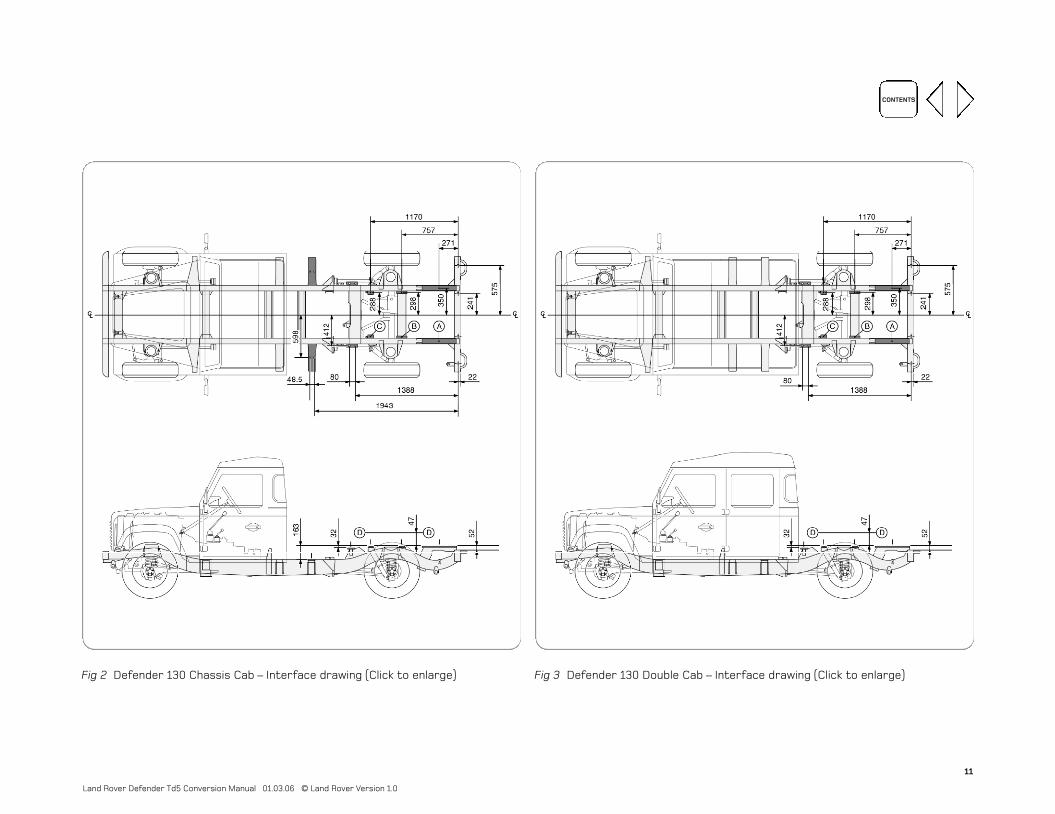
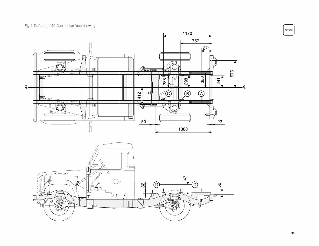
4.2.1 DEFENDER – INTERFACE DRAWINGS
110 Standard and Heavy Duty Cab - Fig 1
130 Cab - Fig 2
130 Double Cab - Fig 3
NOTE: The dimensions shown on the Interface drawings are nominal and subject
to normal production tolerance variations. These drawings are not to scale.
Points ‘A’, ‘B’ and ‘C’ on the Interface drawings are the theoretical centres of
the bearer surfaces which provide additional support (if required) for mounted
equipments/structures.
Plane ‘DD’ represents the minimum wheel arch height.
Due to constant engineering improvements, the Converter is advised to check
the chassis frame of the received vehicle against relevant interface drawing.
Fig 1 Defender 110 Cab - Interface drawing (Click to enlarge)
11
CONTENTS
Land Rover Defender Td5 Conversion Manual 01.03.06 © Land Rover Version 1.0
Fig 2 Defender 130 Chassis Cab – Interface drawing (Click to enlarge)
Fig 3 Defender 130 Double Cab – Interface drawing (Click to enlarge)

12
CONTENTS
Land Rover Defender Td5 Conversion Manual 01.03.06 © Land Rover Version 1.0
5.1 CHASSIS MODIFICATIONS
As already mentioned the Converter may not cut, drill or weld to the Defender
chassis. Land Rover shall not be liable for any death, personal injury or damage to
property arising as a direct result of the failure of the Converter to comply with
this direction.
5.2 OPERATING CLEARANCES
Certain minimum operating clearances must apply to various areas of the body,
chassis and engine in order to prevent fouling.
Rear Wheel Arch Clearances
Adequate clearance shall be provided for the rear wheels, the Converter must
ensure that no foul conditions can occur when the axle is either at full bump
(metal to metal) or at full articulation. The wheel box height must be a minimum
of 47mm above the bearer plane identified by points A, B and C on the Interface
drawings. The inner face of the wheel box must be positioned so that the inside
edge is no more than 535mm from the vehicle centre line.
Engine and Exhaust Clearances
It is important that adequate clearances are allowed in the areas around engine
and exhaust components that are likely to get hot. There are two main reasons;
firstly the component may become damaged by the heat of the exhaust/engine,
and secondly the new component will affect the air flow over and round the hot
component leading to possible overheating of the engine. Also the engine and
exhaust components must be allowed to move on their mountings.
Chassis Clearances
Any additional equipment must still allow full movement of all systems and
components. To ensure that this is the case it is recommended that a minimum
clearance of 50mm is allowed from the extremes of all moving parts. The most
usual systems that will require such clearances are chassis related steering
and suspension parts. These clearances will also apply to all rotating machinery.
5.3 MOUNTING TO THE CHASSIS
There have been a variety of body mounting systems and types used on
Land Rover vehicles over the years. The basic principles of body mounting
are however quite simple as defined below.
Where rear body construction is similar to that of Defender and the loads
carried are similar to those normally carried and spread over a large area,
the existing body mounting points identified on the interface drawings are
sufficient. If the load is concentrated and represents a high proportion of
vehicle payload then it is important to provide a sub frame or attach the
payload to a full length frame. If the equipment is provided already attached
to a sub frame then it is important that this sub frame is adapted to bolt on
to the Land Rover chassis frame. The principles for sub frame mounting are
the same as for body mounting.
The body/sub frame should be rigidly mounted at the rear of the chassis.
This should consist of a sub frame cross member resting on top of the rear
chassis cross member and bolted at all 4 mounting points across the frame.
5. CHASSIS, SUB FRAMES & BODY MOUNTING
13
CONTENTS
Land Rover Defender Td5 Conversion Manual 01.03.06 © Land Rover Version 1.0
The front attachment should be as far forwards as possible, directly behind
the vehicle cab, bearing in mind the minimum body to cab clearance specified
in section 4. It is important to design the subframe to prevent twisting of the
chassis members.
In between these main front and rear attachments, the body subframe should
rest on all of the body bearers that are provided on the chassis. These bearers
should not be drilled and bolted to, but rather the subframe/body should rest
upon them to allow a certain amount of movement. These bearers and the
subframe upon them should be protected by the use of 5mm thick balata or
canvas reinforced rubber strips.
The body should have support for its full length by way of longitudinal stringers
or alternatively cross members above every bearer. The nature and size of these
stringers and cross members will depend upon the construction of the body.
For applications where a flat floor is required, such as a flatbed or tipper,
it may be necessary to increase the depth of the subframe to bring the
floor up to a sufficient height to give adequate rear wheel arch clearances.
The same effect may be achieved by the use of pedestal mountings but
attention should be given to prevent the mountings from lozenging under heavy
braking/cornering.
All of the above applies to alternative bodies or concentrated payloads which are
mounted on sub frames.
NOTE: Where metal faces are bolted together always interpose a suitable
interface material such as weldable zinc rich primer, extruded strip or zinc tape.
NOTE: Paint and finishing of body panels to be in accordance with Land Rover
service paint and refinishing manual.
5.4 STABILISER LEGS
On vehicles which exhibit a very high centre of gravity when in an operating mode
it will be necessary to provide stabiliser legs. These legs may then be lowered
when the vehicle is operating stationary to give extra stability and prevent
overloading of the vehicle chassis. Depending upon the nature of the conversion
it may be necessary to provide either one or two pairs of stabiliser legs.
These legs should be attached to the subframe that attaches the conversion
to the chassis at the discretion of the Converter.
14
CONTENTS
Land Rover Defender Td5 Conversion Manual 01.03.06 © Land Rover Version 1.0
5.5 SECURING OF LOOSE EQUIPMENT
The Defender is capable of operating both on metalled roads and over cross
country terrain and any equipment that is provided in the vehicle must be
securely fastened.
The toolkit, jack etc. in the base vehicle is held in position when they leave
the factory and it is important that if these components are moved they are
held secure in their new position. Similarly, any additional equipment that is
provided must not be allowed to move when the vehicle is operating off-road.
Smaller equipment is often stored in drawers or cupboards but larger, heavier
equipment should be independently secured to the vehicle floor or similar.
If workbenches, cupboards, racking etc are provided then these should be
supported on the vehicle floor and attached to the vehicle body as appropriate.
The method of securing the equipment varies with applications but should always
prevent the equipment from moving when secured but also allow it to be easily
removed when required. Typical designs include locking straps, over-centre
catches, locking pins etc.
Doors and drawers on all cabinets and cupboards should be of the locking type
so that they will not open accidentally when the vehicle is cornering or operating
at an angle.

CONTENTS
Introduction
As well as the specific guidelines for certain areas such as weight distribution
etc, there are several general guidelines that will apply to many areas of all
conversions. This section of the manual gives information relating to conversion
aspects affecting the function and performance of the complete vehicle.
The Converter must ensure that the capability, via design load cases of
components and structures including fixings and retentions, is to a standard
which recognises shock loads up to 5g, when the vehicle is operating off-road.
Please note that although comprehensive, these guidelines are not exhaustive
and it is the Converter’s responsibility to ensure that all work undertaken
complies with any relevant legislation, is safe and is fit for purpose.
6.1 GENERAL VEHICLE CONVERSION DO’S & DON’TS:
DO:
• Maintain the structural Integrity of the vehicle.
• Design alternative or additional structure to disperse loads directly and
evenly to existing vehicle structure, avoid stress concentrations which can
reduce the working life of a structure.
• Ensure attached structures are stiff enough to prevent any adverse
effect on vehicle handling (eg 'swaying' of a box body).
• Repair and repaint exposed metal edges after cutting or drilling work.
• Seal all fixings through floor sides or roof of vehicle.
• Take care to avoid fuel tank damage when drilling the floor area.
• Take care to avoid seat belt & reel damage when working in the vicinity
of the vehicle B pillars.
• Protect all metal edges to comply with exterior and interior
projection legislation.
• Use all the reinforced chassis mounting points for body or
sub-frame mounting.
• Ensure that any additional equipment in the region of the fuel tank will not
damage the tank in a crash condition.
• Ensure that adequate heat shielding is maintained around the exhaust and
catalytic converter, where excessive heat can build up.
• Maintain critical reinforcing straps and fixings through the cab back panel
to the chassis member.
DON’T:
• Drill into closed frame body sections.
• Interfere with seat fixings or structure. All seats have been tested and
approved to both EEC 82/318 and ECE 14.02 which must be maintained for all
European territories.
• Weld to the vehicle structure. Heat affected zones can weaken a structure,
and damage the corrosion protection of the vehicle.
• Clamp around side members as these loads may crush unsupported
box sections.
• Attach unpainted metal surfaces directly to the vehicle unless they are
suitably protected.
6. TECHNICAL GUIDELINES
15
Land Rover Defender Td5 Conversion Manual 01.03.06 © Land Rover Version 1.0
16
CONTENTS
Land Rover Defender Td5 Conversion Manual 01.03.06 © Land Rover Version 1.0
6.2 VEHICLE DESIGN GUIDELINES
The Land Rover Defender has been designed to suit many varied and demanding
uses. Its design takes into account:
• Safety – safe operation and use of the vehicle is the most important aspect
of its design and manufacture.
• Function – how the vehicle will be used and what its job will be; Duty Cycle –
how the owner/operator will use the vehicle on a typical day’s work.
• Durability – how the vehicle will perform during its life, avoiding impaired
function through wear and tear.
• Reliability – how the vehicle will perform during its life, avoiding breakdown
or failure of any system.
• Quality – consistency of manufacture and the correction of build variability
which could impair the vehicle performance.
• Serviceability – how the vehicle can be easily and cost effectively serviced
or repaired during its life.
• Cost of Ownership – how the vehicle will be cost effective to purchase,
run, service, and how to minimise the vehicle depreciation.
• Recycleability – material choice is important for quality functioning of
the vehicle, but should also comply with recycleability legislation.
Any conversion to the Land Rover Defender should consider these basic design
requirements from the outset.
6.3 SAFETY
Safe design for operation and use of the vehicle is essential, but this must
also be supported by failure prevention to avoid unintended vehicle or
equipment operation.
Failure Modes and Effects Analysis
Consider, at the design stage, the proposed function of a conversion
and the potential failure modes and effects of such failures on the
operation of the vehicle.
Listed here are the key points which should be used in a failure mode and
effects analysis, applicable to any design:
• Function – define the function or requirement of the vehicle,
system or component;
• Potential Failure Mode – what can go wrong:
• No function.
• Partial/Over/Degraded Function.
• Intermittent Function.
• Unintended Function.
• Potential Effect(s) of Failure – what are the effects.
• Failure Classification – how bad is the failure mode – quantify severity.
• Potential Failure Cause(s) – what are the Cause(s).
• Failure Frequency – How often does the failure happen –
quantify occurrence frequency.

CONTENTS
• Failure Control – How can the failure be prevented and detected? – quantify
Detection Certainty;
• Control Confidence – how effective is the control process at identifying faults?
• Recommended Action(s) – what can be done?
• Design changes.
• Process changes.
• Special controls.
• Changes to standards, procedures or guides.
6.4 VEHICLE FUNCTION AND DUTY CYCLES
6.4.1 GENERAL
The first stage of any conversion should be the consideration of who will
use the vehicle and how it will be used. This sets the design parameters.
In addition to general vehicle functions, the function of any specific equipment
should be considered, e.g. does an auxiliary heater provide the required vehicle
temperature, does a lamp give out sufficient light for its expected use etc.
6.4.2 ELECTRICAL DUTY CYCLE GUIDELINES:
When fitting any electrical equipment to vehicles it is important to consider
the following:
• Quantify the electrical load (amp hours out).
• Identify the typical duty cycle of the finished vehicle (giving an indication
of amp hours in).
• Order the vehicle with a suitable electrical system.
6.4.3 CONVERSION EFFECT ON SPECIFIC PERFORMANCE ASPECTS OF THE VEHICLE
Conversion Effect on Appearance
The appearance of the vehicle is a result of the vehicle function and
package requirements, and also the company’s design intent for the vehicle.
Where a conversion can be produced to complement the base vehicle design
it is encouraged.
Conversion Effect on Ergonomics
The layout and design of the vehicle controls have been produced to suit the
majority of customers (i.e. most of the population would be able to find a
comfortable position with respect to the vehicle controls in order to reach
and operate them). Operation includes not only major controls such as steering
wheel, pedals, gearlever and handbrake, but also minor controls such as switches
and sight lines via mirrors and glazing etc. Obstruction or interference with any
of these access or sight zones can impede the safe operation of the vehicle and
are therefore not permitted.
Conversion Effect on Fuel Economy/Performance
The fuel economy and performance figures advertised for Land Rover Defender
relate to unconverted, factory complete products. Any changes to the weight
or size (in particular frontal area) of a vehicle can affect fuel economy
and performance due to changes in rolling resistance or aerodynamics.
It is advisable to control the weight using lightweight material but without
deteriorating the other vehicle attributes and functions (especially those
related to safety and durability).
17
Land Rover Defender Td5 Conversion Manual 01.03.06 © Land Rover Version 1.0

18
CONTENTS
Land Rover Defender Td5 Conversion Manual 01.03.06 © Land Rover Version 1.0
Conversion Effect on Vehicle Ride and Handling
The limits of axle plate, gross vehicle mass, trailer plate and gross trailer
mass must not be exceeded.
Changing the running weight and/or load distribution of a vehicle affects its ride
and handling characteristics. Loading a vehicle within the C of G guidelines will
maintain the manufacturer developed ride and handling standards. Within these
guidelines optimal ride and handling can be achieved by distributing vehicle
load evenly from front to rear and laterally according to axle capacities.
Changes to aerodynamics can also affect the vehicle’s ride and handling.
The ride and handling of the finished vehicle should be evaluated for safe
operation prior to sale/use.
Conversion Effect on Brake Performance
The vehicle braking systems have been developed and tested to comply with
current legislation. Loading the vehicle outside the recommended C of G
guidelines will degrade this performance standard and is prohibited. Any changes
to the braking system from suspension to tyres, including actual brake
components (disks, pads, drums, shoes etc), can degrade the performance of the
whole vehicle braking system, and are therefore not permitted.
Conversion Effect on EMC/RFI Performance
Adding any electrical content can create electrical interference in other
systems or be affected by electrical interference from other vehicle systems
or external electrical sources. If any of these systems is very sensitive to this
interference it can cause a malfunction of the system. EMC & RFI testing is
part of the development process to reduce these levels of interference to
acceptable levels where any malfunction will not occur.
Examples of noisy sources are:
Alternator or motor systems; high levels of fluctuating voltage or current.
Examples of sensitive systems are:
Generally electronic systems where small levels of interference can have
a large effect on a low voltage/current circuit, e.g. engine management
systems, ABS systems, airbag modules, central locking modules etc.

CONTENTS
Conversion Effect on Occupant Protection
A laden moving vehicle contains a massive amount of energy. When a vehicle is
involved in an impact this energy is dissipated and absorbed by the deformation
of the vehicle structure. The structure of the vehicle has been designed
to maximise the safety of the occupants in the event of an accident. Safe
performance involves the controlled deceleration of the occupant with the
assistance of restraints, as well as the absorption of energy in the vehicle
crumple zones, retaining as much of the occupant space intact as possible.
Any parts or structure added to the vehicle should not interfere with the
performance of the crumple zone, the occupant survival space, the door
open-ability, the designed deployment of the belts, pretensioners or other
restraint devices, and the safe deceleration of the occupants.
Don’t interfere with seat fixings or structure. All seats have been tested
and approved to current legislation which must be maintained for all
European territories.
Conversion Effect on Critical Components
No Drill Zones, Fuel, Brake Line, Box Sections, Electrical, etc.
When converting a vehicle it is often necessary to drill the vehicle bodywork.
Be aware of critical components around the vehicle which must be avoided.
These include
•Fuel system (tank, lines, coolers, etc.).
•Brake system (hydraulic lines and valves, handbrake cable and mechanisms).
•Electrical circuitry, connectors & components.
•Seat belt and reel.
•Closed box sections.
Conversion Effect on Rear and Side Underrun Protection
If an incomplete vehicle is converted, the converter should ensure that the
vehicle is equipped with a side and rear underrun guard, if this is applicable
to that classification of vehicle.
Conversion Effect on Water Ingress
Seal all fixings through floor sides or roof of vehicle.
Conversion Effect on Heat Management
Ensure that adequate heat shielding is maintained around the exhaust and
catalytic converter where excessive heat can build up.
Conversion Effect on Interior & Exterior Projections
•Protect all metal edges to comply with exterior and interior projection legislation.
•Ensure that any additional equipment in the region of the fuel tank will not
damage the tank in a crash condition.
Conversion Effect on Vehicle Structure
Vehicle structure must not be removed or modified during conversion.
Incomplete Vehicle Transportation Guidelines
(Wheel Guards, Brake System Ballast, etc.)
Some vehicles built specifically for subsequent conversion may leave Land Rover
as incomplete vehicles. This includes chassis cab vehicles, vehicles with
19
Land Rover Defender Td5 Conversion Manual 01.03.06 © Land Rover Version 1.0

CONTENTS
incomplete body structure etc. The Converter should be aware of the
roadworthiness of incomplete vehicles, and move the vehicles accordingly.
Major examples of such vehicles are:
Chassis Cabs without floats – may have no rear wheel guards, the braking
system may not be balanced for a light rear axle.
Temporary Driver’s seat – permits vehicles to be loaded/unloaded from
a transporter but are not roadworthy.
Chassis Cowl vehicles – have incomplete body structure.
Temporary structure – removable roof/back-panel, or temporary rear
door aperture panel.
6.5 VEHICLE DURABILITY AND RELIABILITY
Vehicle Durability
Vehicle Durability is a measure of how well the vehicle performs during and
after a significant working life of “wear and tear”. This is closely related to the
Function and Duty Cycle of the vehicle which could mean the vehicle has spent
its life running up and down motorways doing a long haul parcel delivery job
or has spent its time parked with its engine running powering an accessory
drive to operate an on-board crane, tipper or refrigerated unit.
Understanding the duty cycle and then how often a system or component
will be used or operated, and in what range of environments it will operate
(temperature, dirt, water etc) is key to establishing how durable the design
needs to be to serve an acceptable life (10 years or 150,000 miles) without
suffering an impaired function.
Examples of impaired function are:
• Slop in mechanical linkages such as hinges, locks, switches etc.
• Riveted constructions fretting, and loosening.
• Corrosion of metal structure.
• Hardware working loose.
• Mechanisms seizing.
• Pipework becoming clogged due to filter system failures.
• Trim wearing prematurely.
• Components fatiguing through overloading their design capability.
• Reducing body strength or rigidity increasing fatigue risk.
Vehicle Reliability
Vehicle Reliability is a measure of a vehicle remaining operational for a significant
working life without fundamental system or component failure on which the
vehicle directly relies.
Understanding the criticality of the vehicle’s dependence on certain components
and systems, and maximising the reliable operation of these systems to avoid
failure is key to designing for reliability.
Examples of unreliable function are:
• Flat batteries causing an immobilised vehicle due to not running a charge
balance system.
• Non-functional lighting system due to poor quality aux lighting connection failure.
• Emptying the fuel tank by running a fuel fired heater with a stand pipe which
reaches the bottom of the tank.
• Water ingress and corrosion on electrical connectors.
20
Land Rover Defender Td5 Conversion Manual 01.03.06 © Land Rover Version 1.0
CONTENTS
6.6 VEHICLE QUALITY AND REFINEMENT
Build Quality and Repeatability
Any conversions should be designed and manufactured to ensure that any
variability between units is minimised. This can be achieved by identifying
critical characteristics of:
• Design feature (e.g. critical dimension or tolerance).
• Component or system test / inspection (e.g. the function of a subcomponent).
• Manufacturing or assembly process (e.g. remove manual rework and
introduce jig and fixture tooling) which is key to the performance of
the finished product.
Conversion Effect on Vehicle Appearance, Fit and Finish
A conversion which may change or add to the overall appearance of the base
Land Rover product should match quality characteristics of fit and finish such
as gaps, surface finish, colour, cleanability etc.
Conversion Effect on Design Robustness
Design robustness is the ability of a vehicle or piece of equipment to perform
consistently under varied operating conditions. Examples of where variables
can occur are:
• Design/Manufacturing variability: raw material variability, tolerance variability.
• Changes over time/mileage: wear, rigidity changes, shrinkage/distortion,
embrittlement, hardware torque loss.
• Duty Cycle/customer usage: door slam, heavy loads/tools damage; ingress of
dirt & liquids into trim, joints, seals etc.
• Environmental: weather variations, road conditions, animal or plant damage,
industrial fallout, coastal salt, road grit.
• In-vehicle environment: engine / heater heat, condensation, vibration etc.
Conversion Effect on NVH (Incl Squeaks & Rattles)
NVH is the Noise, Vibrations and Harshness performance of the vehicle.
Consideration shall be given to the potential effects of the conversion
on the overall NVH of the vehicle.
It is the Converter's responsibility to ensure compliance with any relevant
legislation relating to operator exposure to noise and vibration.
Corrosion Performance
Repair and repaint exposed metal edges after cutting or drilling work.
Do not weld to the vehicle structure. Heat affected zones can weaken
a structure and damage the corrosion protection of the vehicle.
6.7 VEHICLE SERVICEABILITY
Design for Service
Most vehicle systems will need some degree of service attention either regular
maintenance, wear-out replacement or damage repair. The vehicle should be
designed to minimise the time it takes to conduct the service by ensuring easy
access or part removal to do the job. Design features which help the
serviceability of vehicles are:
• Use readily available components, hardware and standard assembly tools.
• Ensure systems can be disassembled and reassembled easily and
without breakage.
• Provide clear instructions for servicing, disassembly and reassembly.
• Ensure systems breakdown to small components where damage may be
isolated or sacrificial wear is incurred.
21
Land Rover Defender Td5 Conversion Manual 01.03.06 © Land Rover Version 1.0

CONTENTS
• Use fixing methods and materials which are compatible and do not corrode
or get blocked by dirt.
• Provide diagnostic and fault finding instructions if necessary.
• Provide specialist help and service support if required.
• Record vehicle build and chassis number information alongside any component
batch information for tracing quality or build problems in the field.
Base Vehicle Servicing
It is important that any conversion on a Defender does not have a detrimental
effect on the access to any area of the vehicle and the serviceability of the
vehicle. Access to all serviceable parts must not be hindered by a conversion
and if there is any doubt it is recommended that the component or system in
question is removed and replaced in accordance with the Land Rover workshop
manual to ensure that these operations are still possible. It is important that
any conversion does not hinder access to perform fluid level checks.
If the Converter needs to remove and replace any Land Rover components this
should be done in accordance with the Land Rover workshop manual which will
also include the torques for any fixings which should be used. The Converter
must also fit new gaskets and nuts fitted with Nylon inserts whenever these
have been removed. The Converter should use fixings of the same size and
thread form as those used by Land Rover whenever possible to allow for
easier servicing.
Standard parts should be used wherever possible and certain Land Rover
components can be used to give a high level of commonality and easier parts
supply. Spring washers should not be used on fixings. It is the responsibility of
the Converter to provide servicing maintenance instructions for any systems or
components that are in addition to the Defender (See section 6.8).
Conversion Servicing
Identify a clear service schedule for any added equipment, with recommended
service centres in the market in which the vehicle is sold.
6.8 OPERATORS’ INSTRUCTIONS AND PARTS LISTINGS
It is the responsibility of the Converter to provide all of the necessary
information along with his conversion equipment. This aspect of the
conversion is extremely important but is often overlooked to the detriment
of the total vehicle.
Operators’ Instructions
The Converter or equipment supplier must supply along with his equipment an
operator's handbook. This must give a brief description of the system's
operation, a full guide to operating the system in all of its operating modes and
also identify all special safety precautions that need to be taken whilst operating
the system. The size and format of this document will vary according to the
nature of the equipment but it is essential that some guidelines are given.
22
Land Rover Defender Td5 Conversion Manual 01.03.06 © Land Rover Version 1.0

23
CONTENTS
Land Rover Defender Td5 Conversion Manual 01.03.06 © Land Rover Version 1.0
Service Guide
If any part of the conversion/equipment has servicing requirements then it is
important that these are also supplied along with the operators’ instructions.
The service intervals must be clearly stated and wherever possible these should
coincide with the service intervals of the host vehicle (available from the vehicle
handbook). The conversion equipment should, wherever possible, be maintenance
free with the emphasis on parts replacement rather than repair.
Parts Listing and Spares Supply
The Converter also has a responsibility to keep records of what parts are
included in a conversion and the ability to supply spare parts on request for a
minimum period of 10 years. This may take the form of drawings of all special
components or alternatively a stock supply of spare parts.
If the parts are standard then the Converter supplier must keep records of
these for future supply. Ideally the Converter supplier should supply a full parts
listing and exploded drawing for his equipment to allow easy ordering of spare
parts as necessary by the end customer.
6.9 LABELS, GUARDS AND GAUGES
External Projections and Guards
The Converter is responsible for ensuring that no part of his conversion
will form a dangerous external projection. This will also apply to sharp edges,
rotating or reciprocating machinery, very hot or very cold surfaces and
other features that are liable to cause injury or damage. If it is not possible
to re-design the particular item causing the problem then it will be necessary
to provide a guard to prevent any person from gaining access to it.
Provision of Labels
Labels must be provided on the vehicle or equipment wherever the additional
information would be of benefit to the operator. These labels may be in the form
of warning labels adjacent to the possible danger. An example of this would be a
label on the rear of a vehicle cab to warn people of the dangers of working under
an unpropped tipper body. The label may also be advisory to aid the operator.
An example would be a label defining the required sequence of operation of a
system. The third class of label is for identifying switches, gauges, instruments
etc. These labels should clearly identify what the device is for, its operation and
the importance of each position. As an example, a label would be required for a
hydraulic valve indicating what the switch is for (hydraulic changeover valve)
how to operate it (push pull) and what each position is for.
The size and type of label will depend upon the location but it should be
positioned as near as possible to the controls, danger or system to which it
refers. The label itself should be capable of withstanding the conditions under
which it is expected to operate. Any label on the outside of the vehicle should be
of the engraved or embossed type and should be either screwed or riveted to
the vehicle body. Labels inside the vehicle may be of the ‘stick on’ type but must
still be securely fixed to the vehicle. International standards for label colour,
size and design should be followed wherever possible.

CONTENTS
WARNING: Should the performance of the converted vehicle be significantly
different to that of the standard vehicle, then the Converter shall provide
suitable warnings in appropriate places on the vehicle for the benefit and safety
of the driver/operator.
Gauges
If the Converter supplies any additional equipment or system then he should
provide gauges to indicate the state of the system. These gauges could be
for example pressure, temperature and flow gauges for a hydraulic system.
The gauges themselves should be clear and easy to read and graduated in
metric or S.I. units wherever possible. All danger levels should be indicated on
the gauge as well as the normal operating range. The gauge should be labelled
to identify what it is referring to and should have a light to allow it to be read
after dark. The position of the gauge should be such that it can be clearly seen
from the operator’s usual position.
6.10 VEHICLE COST OF OWNERSHIP
Whole Life Costs
Customers are increasingly aware of whole life vehicle costs, taking into
consideration long term aspects of vehicle ownership, which depend on all
the following factors:
• Purchase cost.
• Running costs.
• Fuel economy.
• Insurance costs.
• Servicing Costs - Servicing costs should take into account not just the
replacement part costs but also the ease of servicing, and therefore the
labour costs involved.
• Residual Value - This one of the main aspects of cost affected by conversions.
Any change to the versatility of use of the vehicle will restrict the second hand
market for the vehicle unless the conversion is sought after in the aftermarket.
Many second hand vehicle buyers further convert the vehicle back to a more
general purpose vehicle. Features such as added equipment or body reworks
should consider the effect it may have on further conversion or resale value.
6.11 END OF LIFE VEHICLE DIRECTIVE – MATERIAL RESTRICTIONS
AND RECYCLEABILITY
The EU End-of-Life Vehicle (ELV) directive requires that environmental and
recycling aspects be integrated in the development process of new components
and vehicles. This includes requirements with respect to:
• The overall recycleability (85%) / recoverability (95%) of vehicles.
• Limited use of hazardous substances including the elimination of prohibited
substances (e.g. lead, hexavalent chromium, cadmium and mercury).
• Publication of dismantling information.
• Parts Marking according to the corresponding ISO Standards: ISO 1043-1,
1043-2 and 11469 for plastics and ISO 1629 for rubber materials.
• Increasing use of recycled materials.
• Producers meet all, or a significant part of, the costs to take back end-of-
life vehicles.
24
Land Rover Defender Td5 Conversion Manual 01.03.06 © Land Rover Version 1.0
CONTENTS
In addition to the requirements resulting from the End-of-Life directive, other
environmental targets should be taken into consideration such as:
• Minimizing costs and environmental burden along the product life-cycle.
• Maximizing use of renewable materials e.g. natural fibres.
• Minimize the presence of substances impacting vehicle interior air quality/
clean compartment or allergenic reactions, taking into account smell, fogging,
toxicity and allergy etc. emanating from the interior trim.
• Eliminate use of prohibited substances which are listed in the Global Automotive
Declarable Substance List GADSL (http://www.gadsl.org/).
For continued legal compliance and environmental performance of all Land Rover
products, it is essential that any conversion shall be in compliance with the
requirements listed above.
This is not a complete list of all legal requirements to be met by every converted
vehicle. For further information please contact the responsible
Certification/Homologation Authority or National Sales Company representative.
25
Land Rover Defender Td5 Conversion Manual 01.03.06 © Land Rover Version 1.0

26
CONTENTS
Land Rover Defender Td5 Conversion Manual 01.03.06 © Land Rover Version 1.0
7. WORKING PRACTICES
7.1 GENERAL
This section provides general engineering and workshop practice guidance
for Converters.
7.1.1 ELECTRICAL CIRCUITRY (GENERAL)
Whenever additional electrical circuits are required on a vehicle there are
several options that may be considered. The first and most simple method is to
take a feed from the existing fuse box. This must be from the fused side of the
fuse box. In these cases it is not acceptable to increase the fuse rating of the
existing fuse in order to cater for the additional current draw. The second
alternative would be to provide a separate circuit with its own separate fuse or
even an additional fuse panel. It is essential to check on the current draw of any
new circuits provided on the vehicle. Any equipment that has a high current draw
but is only used occasionally and usually with the engine running will require a
heavy duty battery to maintain starting ability. Equipment that is to run for long
periods of time with the engine off, such as warning beacons, will require that
the vehicle be fitted with a split charge system to prevent the main vehicle
battery from being drained.
However the circuit is designed, the Converter must provide a circuit diagram
for the circuit in accordance with section 6.8. It is important that no additional
circuitry interferes with the flasher circuit.
7.1.2 SWITCHES AND RELAYS
Any additional switches that are provided for new circuits must be of a rating
suitable for the application. If the current is greater than the switch rating then
it will be necessary to connect the switch to a relay that will operate the circuit.
Relays should also be used for all circuits that are required to carry a current in
excess of 0.5A. All switches should be positioned for easy access and visibility
and should be lit whenever possible to allow ease of operation after dark.
There may be positions on the vehicle dashboard centre panel for additional
switches or alternatively an additional switch panel may be provided within easy
reach of the vehicle driver. All switches and warning lamps should be clearly
labelled as to their function and operation with all positions of multi-position
switches being identified. (See section 6.8).
7.1.3 ELECTROMAGNETIC COMPATIBILITY (EMC), INTERFERENCE
SUPPRESSION AND LEGAL
The base vehicle has been tested and certified to all relevant legislation relating
to electromagnetic compatibility and interference suppression. All retro-fitted
equipment must also comply with the relevant legislation. Post installation
checks must be made for disturbances from and to all electrical equipment in
the vehicle in both standby and transmit modes. Checks should be carried out
with the ignition ON, engine running and followed by a road test at various speeds.
27
CONTENTS
Land Rover Defender Td5 Conversion Manual 01.03.06 © Land Rover Version 1.0
7.1.4 LIGHTING - LEGAL
When the vehicle leaves the factory the vehicle's electrical system is in
accordance with the legal requirements for vehicle lighting and it is the
Converter's responsibility to ensure that these standards are still met.
For example, when a unique body is fitted then the Converter will need to
ensure that the legal requirements for front and rear light visibility are still met.
7.1.5 WIRES AND CABLES
There are certain standards within the motor industry that relate to wiring and
connectors and these must be observed when providing any additional electrical
systems on the vehicle. Any additional wiring that is provided must be of the
correct rating and type for the current that it is to carry. Similarly any additional
circuits may not increase the current flow through existing wires and cables
without first checking on the rating of those components. In order to reduce the
possibility of wires and cables overheating it is advisable not to group or bunch
wires such that they have a tendency to heat each other. In order to maintain
commonality it is recommended that the colour coding used on the base vehicle
is used wherever possible.
7.1.6 CONNECTORS
Additional circuits on the vehicle will inevitably require connectors and it is
important that these are of the correct type for the application. Connectors
should be avoided in vulnerable areas to help prevent damage and water ingress.
If it is necessary to provide a connector in an exposed location then it must be
of the weatherproof self-locking type with the live wire in the shrouded half
of the connector. It may occasionally be necessary to provide a weatherproof
junction box for more complicated installations and this must be mounted
in an easily accessible area with good protection from water and mud.
Any connector used in the interior of the vehicle must still be fully shrouded.
Ring type terminals may also be used but the tear-out forces must be sufficient
for the application. Exposed live terminals should be protected using the mating
half of the connector.
CAUTION: It is not acceptable to use insulating tape on connectors or
Quicksplice connectors of the ‘Scotchlox’ type.

28
CONTENTS
Land Rover Defender Td5 Conversion Manual 01.03.06 © Land Rover Version 1.0
7.1.7 ROUTING OF WIRES AND CABLES
All additional wiring must be correctly routed to prevent damage to both the
harness itself and to associated components. When planning a harness route
several guidelines must be followed. The vehicle body must be capable of being
removed without removing the harness. All wiring must be kept 50mm clear
of the extremes of all moving parts and at least 100mm clear of very hot
components such as the exhaust pipe. Whenever wires are required to pass
through panels it is essential that a grommet is provided to prevent leaks
and damage to the wire. It is not acceptable to pass additional wiring through
existing grommets. New holes and grommets will need to be provided.
Any additional wiring and harnesses must be securely clipped to the body/chassis
or similar using plastic or plastic coated metal clips. It is important that these
clips do not damage the insulation on the wire in any way. It is not acceptable
to clip wiring to fuel or brake pipes. Wiring clips should be at a maximum spacing
of 300mm. It is important to check that no wire or cable route will interfere
with the full movement of any component or system
7.1.8 PRECAUTIONS WHEN WELDING
Before any welding is done to the vehicle it is important that the vehicle battery
and alternator should be removed or disconnected in order to prevent damage
to the vehicle's electrical system. The welding earth strap should wherever
possible be attached directly to the component being welded.
CAUTION: All ECU’s (Electronic Control Units) shall be disconnected before
any welding operations are carried out on the vehicle.
7.2 PAINT AND PROTECTION
If for any reason the paint or protective finish of the base vehicle is removed
or damaged, the Converter/Coachbuilder shall repair it in accordance with the
Land Rover Body Repair Manual.
7.3 HEALTH AND SAFETY
Materials used in the painting and stripping processes can be hazardous to
health unless the appropriate safety precautions are closely observed.
There are general rules contained within the various laws and factories acts
applying to the use of hazardous substances, compressed air etc and these
should be followed along with any additional recommendations made by the
suppliers of either equipment or materials. Most paints and strippers are
volatile substances and hence their storage should be carefully planned
and supervised. Also the use of any such substances should be only within
well-ventilated areas. Do not smoke whilst using these substances.
Protective clothing should be worn when using paint stripper, rust remover,
cleaning fluid or paint. If any of these substances are in contact with the skin
or eyes then wash immediately with copious amounts of cold water. In the event
of contact with the eyes then contact a doctor without delay.
CONTENTS
7.4 PIPEWORK
7.4.1 MATERIALS
The Converter should use Land Rover materials, or materials to the same
specification as those used by Land Rover, for all pipe and hose installations.
For any installation that involves existing systems on the vehicle the Converter
must use pipes and hoses compatible with those already being used. For any
additional systems that are provided the Converter must use pipework and
hoses that are of the correct size, type and rating for the application.
7.4.2 ROUTING
One of the most common failings of conversions is poor pipe and hose routing.
This can be avoided with a little extra thought and care and its importance
should not be under-rated. Poor hose layouts will lead to undue stress on
connections and to wear and eventual failure of the hose and hence the system.
Most of the points made in section 7.1 under electrical cable routing such as
clipping, free play, clearances, grommets etc. will also apply to pipes and hoses.
Any T-pieces, or similar, should be bolted securely to the chassis or to brackets
attached to the chassis or similar. It is equally as important with rubber hoses
that the hose is not scuffing against any sharp edge as this will soon result
in a failure.
7.4.3 BRAKE PIPES
The Converter should not interfere with the braking system in any way.
The only exception to that rule would be the introduction of a T-piece into
the brake line to actuate the air brakes for the trailer.
WARNING: If any changes are made to the vehicle braking system then
the Converter will be responsible for the Type Approval and testing of the
modified system.
7.5 WELDING
The Converter will occasionally need to perform welding processes and
it is important that the following guidelines are adhered to.
7.5.1 WELDING TO THE CHASSIS
The Converter is not allowed to cut, drill or weld to the chassis frame.
7.5.2 PROTECTION
Before any welding is done to the Converter's installation on the vehicle,
the following precautions must be taken:
• The vehicle battery must be disconnected.
• The vehicle alternator must be disconnected.
• The welding earth terminal must be attached to the actual component being
welded wherever possible or alternatively on the chassis adjacent to the weld.
• Fuel and brake pipes must be protected from the heating effects of welding.
• The electrical harness must be protected from the welding process.
• N.B. The main harness passes inside the right hand chassis frame.
• The vehicle springs must be protected from weld spatter.
• All paint surrounding the area to be welded must be protected.
29
Land Rover Defender Td5 Conversion Manual 01.03.06 © Land Rover Version 1.0
QUIT
30
RETURN
Fig 1 Defender 110 Cab - Interface drawing

31
Land Rover Defender Td5 Conversion Manual 01.03.06 © Land Rover Version 1.0
Fig 2 Defender 130 Chassis Cab – Interface drawing
RETURN
RETURN

32
Land Rover Defender Td5 Conversion Manual 01.03.06 © Land Rover Version 1.0
Fig 3 Defender 130 Double Cab – Interface drawing
RETURN
Recommended