5-Piece All Birch Complete Drum Set (DBX5522)
DBX5522 Drum Set Owner’s Manual
S o u n d P e r c u s s i o n L a b s . c o m

D r u m S e t O w n e r ’ s M a n u a lG R E A T T O N E
ALL BIRC
H
P O W E R F U L P R O J E C T I ON
Thank you for purchasing this Unity Birch set from Sound Percussion Labs’ outstanding line of drums, percussion and hardware.
These instructions should be used as only a general guide. Make adjustments for your comfort and playing style. Experimentation can lead to unique and great experiences in your playing and your music. So experiment with your setup and enjoy!
Also, be sure to visit www.soundpercussionlabs.com for more information on Sound Percussion Labs products and support.
2
Table of Contents
DBX5522 Components 3
Bass Drum Assembly and Positioning 4
Floor Tom and Leg Assembly 5
Mounting the Toms to the Bass Drum 5
Cymbal Stand Assembly 6
Snare Drum Stand Assembly 6
Attaching the Bass Drum Pedal 6
Hi-Hat Cymbal Stand Assembly 7
Assembling the Drum Throne 8
5-PieceDBX5522
One (1) Year Limited WarrantySubject to the limitations set forth below, Sound Percussion Labs™ hereby represents and warrants that the components of this product shall be free from defects in workmanship and materials, including implied warranties of merchantability or fitness for a particular purpose, subject to normal use and service, for one (1) years to the original owner from the date of purchase.
Limits of LiabilityRetailer and manufacturer shall not be liable for damages based upon inconvenience, loss of use of product, loss of time, interrupted operation or commercial loss or any other incidental or consequential damages including but not limited to lost profits, downtime, goodwill, damage to or replacement of equipment and property, and any costs of recovering, reprogramming, or reproducing any program or data stored in equipment that is used with Sound Percussion Labs’™ products. This guarantee gives you specific legal rights. You may have other legal rights which vary from state to state. Some states do not allow limitations on how long an implied warranty lasts, so the above limitation may not apply to you.
Sound Percussion LabsP.O. Box 5111Thousand Oaks, CA 91359-5111
All trademarks and registered trademarks mentioned herein are recognized as the property of their respective holders.
1512-10186

S o u n d P e r c u s s i o n L a b s . c o m3
DRUMS INCLUDES:22 x 16” Bass Drum 14 x 5” Snare Drum (Assembled) 10 x 8” Tom (Assembled) 12 x 9” Tom (Assembled) 16 x 14” Floor Tom 16” Triple Flange Steel Hoops x2 22” Matching Wood Bass Drum Hoops x2 16” Clear Batter Side Drum Head 16” Clear Resonant Side Drum Head 22” Clear Batter Side Drum Head 22” Ebony Resonant Side Front Logo
Drum HeadPair of Wood Tip Drumsticks
(UT Batter Side Drum Heads by REMO)
5-PieceDBX5522
Components
HARDWARE INCLUDES:Cymbal Stand x1 Hi-Hat Stand x1 Snare Drum Stand x1 Bass Drum Pedal x1 Drum Throne x1 Tom Arms with Memory Locks x2 Floor Tom Legs x3 4” Tension Rods with Nylon and Metal
Washers for Bass Drum x162.2 5” Tension Rods with Metal Washers
for Floor Tom x16Drum Key x1
CYMBALS:18” Crash/Ride 14” Pair of Hi-Hats
Hi-Hat Cymbals
Hi-Hat Cymbal Stand
Drum Throne
14” Snare
10” Tom 12” Tom
Tom Arms
Cymbal Stand
16” Floor Tom
Crash/Ride Cymbal
Bass Drum Pedal
Floor Tom Legs
22” Bass Drum
Drum Key
Remo Batter Head
Resonate Head
Snare Drum Stand
D r u m S e t O w n e r ’ s M a n u a lG R E A T T O N E
ALL BIRC
H
P O W E R F U L P R O J E C T I ON
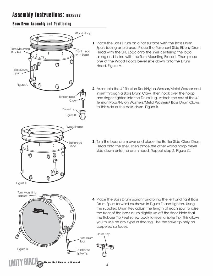
1. Place the Bass Drum on a flat surface with the Bass Drum Spurs facing as pictured. Place the Resonant Side Ebony Drum Head with the SPL Logo onto the shell centering the logo along and in line with the Tom Mounting Bracket. Then place one of the Wood Hoops bevel side down onto the Drum Head. Figure A.
2. Assemble the 4” Tension Rod/Nylon Washer/Metal Washer and insert through a Bass Drum Claw. Then hook over the hoop and finger tighten into the Drum Lug. Attach the rest of the 4” Tension Rods/Nylon Washers/Metal Washers/ Bass Drum Claws to this side of the bass drum. Figure B.
Bass Drum Assembly and Positioning
4
Assembly Instructions: DBX5522
3. Turn the bass drum over and place the Batter Side Clear Drum Head onto the shell. Then place the other wood hoop bevel side down onto the drum head. Repeat step 2. Figure C.
Figure A
Bass Drum Spur
Tom Mounting Bracket Front Head
with Logo
Wood Hoop
Figure C
Batterside Head
Wood Hoop
4. Place the Bass Drum upright and bring the left and right Bass Drum Spurs forward as shown in Figure D and tighten. Using the supplied Drum Key adjust the length of each spur to raise the front of the bass drum slightly up off the floor. Note that the Rubber Tip Feet screw back to revel a Spike Tip. This allows you to use on any type of flooring. Use the spike tip only on carpeted surfaces.
Figure D
Tom Mounting Bracket
Bass Drum Spur
Rubber to Spike Tip
Drum Key
Figure B.
ClawTension Rod
Drum Lug

S o u n d P e r c u s s i o n L a b s . c o m
Mounting the Toms to the Bass Drum
1. Insert long section of the first tom arm a few inches into the Tom Mounting Bracket. Wing nut faces left when standing behind base drum in playing position.
2. Tighten the wing nut on the Tom Mounting Bracket.
3. Loosen the wing nut on the tom arm and angle the top part of the tom arm to just below horizontal and retighten the wing nut. Figure G.
4. Place the Tom Mount of 10” tom onto the tom arm and tighten the wing nut on the tom mount.
5. Repeat Step 1 through 4 for the 12” tom.
6. Adjust height and angle of toms for desired playing.
7. Secure memory locks for additional stability and memory by tightening the collar of the memory lock with the drum key at the mounts of the bass and tom. The next time you need to set up the drums, the memory locks will ensure the same angle and height. Figure H.
5
Floor Tom and Leg Assembly
1. Position the Floor Tom as shown in Figure E. Place the Batter Side Clear Head over the top of the shell. Place one Triple Flange Steel Hoop onto the Drum Head.
2. Line up the holes on the hoop over the Drum Lugs and insert the 2.25” Tension Rod/Metal Washer through the hole into the lug and finger tighten. Attach the rest of the 2.25” Tension Rods to this side of the floor tom.
3. Turn the drum over and place the Resonant Side Clear Drum Head over the shell. Place the other Triple Flange Steel Hoop over the drum head. Repeat step 2.
Figure E
Triple Flange Steel Hoop
Drum Head
Tension Rod
Lug
4. Insert the three Floor Tom Legs into the Floor Tom Brackets as shown in Figure F. Tighten to the desired height and angle for playing.
Figure F
Floor Tom Leg
Floor Tom Bracket
Figure G Tom Arm
Memory Lock
Wing Nut
Tom Mounting Bracket
Wing Nut
Tom Mount
Memory Lock
Figure H
Wing Nut
Bass Drum
Tom
Floor Tom Bracket

D r u m S e t O w n e r ’ s M a n u a lG R E A T T O N E
ALL BIRC
H
P O W E R F U L P R O J E C T I ON
6
Attaching the Bass Drum Pedal
1. Insert the beater into the bass drum pedal sprocket and tighten with the drum key. Figure L.
Beater
Pedal
3. Tighten the wing nut on the toe clamp until secure. Figure N.
2. Attach bass drum pedal to the bass drum hoop via the toe clamp. Figure M.
Toe Clamp
Hardware: DBX5522
Snare Drum Stand Assembly
1. Extend legs to open position and tighten wing nut.
2. Insert upper section that includes snare basket into stand base and tighten the wing nut at the desired height.
3. Adjust the basket to the desired angle with the tilter assembly.
4. Place drum in snare basket. The basket should be adjusted to fit and grip the drum, by tightening Basket Adjustment Wheel counter clockwise. Figure K.
Snare Basket
Tilter Assembly
Height Adjustment
Stand Base Adjustment
Cymbal Stand Assembly
1. Extend legs to open position. Tighten wing nut.
2. Slide upper tube into stand base and set desired height by tightening wing nut. Figure I.
3. Place 18” Ride Crash cymbal in between top and bottom felt. Tighten Cymbal Wing Nut above cymbal only enough to hold cymbal and felts, but loose enough to let cymbal move freely when struck. Figure J.
4. Set desired cymbal angle using tilter adjustment.
Basket Adjustment Wheel
Sprocket
Figure K
Figure M
Figure NFigure L
Wing Nut
Upper Tube
Stand Base
Figure I
Legs
Legs
Cymbal goes here
Tilter Adjustment
Figure J
Cymbal Wing Nut

S o u n d P e r c u s s i o n L a b s . c o m
7
Hi-Hat Cymbal Stand Assembly
1. Slide upper tube over the hi-hat pull rod and into leg assembly. Tighten the wing nut at desired height and secure Memory Lock. Figure O.
2. Place one hi-hat cymbal over the hi-hat rod and onto the cymbal cup with the bottom side of the cymbal facing up.
3. Remove lower retaining nut and one rubber washer from hi-hat clutch. Place the hi-hat clutch through the top of the second hi-hat cymbal, and reassemble the rubber washer and retaining nut under the cymbal. The cymbal should rest between the two rubber washers. Figure P.
4. Place the hi-hat clutch assembly and cymbal onto the hi-hat rod. Tighten the wing nut on the hi-hat clutch with the top cymbal approximately one inch above the lower cymbal. Stepping down on the hi-hat pedal will engage the two cymbals. Figure Q.
NOTE: Adjust Bottom Tilter slightly to let air escape.
Hi-Hat Pull Rod
Upper Tube
Leg Assembly
Close Up Of Hi-Hat Clutch Assembly
Figure O
Clutch
Lower Retaining Nut
Rubber Washers
Top hi-hat cymbal goes here
Figure P Hi-hat clutch and cymbal assembly
Figure Q
Memory LockWing Nut
Bottom Tilter
Cymbal Cup

D r u m S e t O w n e r ’ s M a n u a lG R E A T T O N E
ALL BIRC
H
P O W E R F U L P R O J E C T I ON
8
Assembling the Drum Throne
1. Fold out legs of Tripod Leg Base. Tighten Wingnut.
2. Place upper tube into base and tighten height adjustment bolt and wing nut. Use the second hole position as shown or adjust the height of the throne for your own comfort.
3. Place seat top and tighten wingnut. Figure R.
Seat Top
Wingnut
Height Adjustment Bolt and Wingnut
Figure R
Upper Tube
Tripod Leg Base
Wingnut
Recommended


![[Drum] Benjamin Podemski - Standard Snare Drum Method](https://img.pdfslide.us/doc/110x75/55cf9a8c550346d033a24be8/drum-benjamin-podemski-standard-snare-drum-method-565b15e5232b0.jpg)
![[Drum] Colin Bailey - Bass Drum Control](https://img.pdfslide.us/doc/110x75/5571f30449795947648d5ee9/drum-colin-bailey-bass-drum-control.jpg)