3GPP TR 38.913 V0.4.0 (2016-06) Technical Report
3rd Generation Partnership Project; Technical Specification Group Radio Access Network;
Study on Scenarios and Requirements for Next Generation Access Technologies;
(Release 14)
The present document has been developed within the 3rd Generation Partnership Project (3GPP TM) and may be further elaborated for the purposes of 3GPP.
The present document has not been subject to any approval process by the 3GPP Organizational Partners and shall not be implemented. This Report is provided for future development work within 3GPP only. The Organizational Partners accept no liability for any use of this Specification.
Specifications and Reports for implementation of the 3GPP TM system should be obtained via the 3GPP Organizational Partners' Publications Offices.
3GPP
3GPP TR 38.913 V0.4.0 (2016-06) 2 Release 14
Keywords
Radio
3GPP
Postal address
3GPP support office address
650 Route des Lucioles - Sophia Antipolis Valbonne - FRANCE
Tel.: +33 4 92 94 42 00 Fax: +33 4 93 65 47 16
Internet
http://www.3gpp.org
Copyright Notification
No part may be reproduced except as authorized by written permission.
The copyright and the foregoing restriction extend to reproduction in all media.
© 2016, 3GPP Organizational Partners (ARIB, ATIS, CCSA, ETSI, TSDSI, TTA, TTC).
All rights reserved.
UMTS™ is a Trade Mark of ETSI registered for the benefit of its members
3GPP™ is a Trade Mark of ETSI registered for the benefit of its Members and of the 3GPP Organizational Partners
LTE™ is a Trade Mark of ETSI registered for the benefit of its Members and of the 3GPP Organizational Partners
GSM® and the GSM logo are registered and owned by the GSM Association
3GPP
3GPP TR 38.913 V0.4.0 (2016-06) 3 Release 14
Contents
Foreword............................................................................................................................................................. 5
1 Scope ........................................................................................................................................................ 6
2 References ................................................................................................................................................ 6
3 Definitions, symbols and abbreviations ................................................................................................... 6 3.1 Definitions ......................................................................................................................................................... 6 3.2 Symbols ............................................................................................................................................................. 7 3.3 Abbreviations ..................................................................................................................................................... 7
4 Introduction .............................................................................................................................................. 7
5 Objectives ................................................................................................................................................. 7
6 Scenarios .................................................................................................................................................. 7 6.0 General ............................................................................................................................................................... 7 6.1 Deployment scenarios ........................................................................................................................................ 8 6.1.1 Indoor hotspot .............................................................................................................................................. 9 6.1.2 Dense urban ................................................................................................................................................ 10 6.1.3 Rural ........................................................................................................................................................... 11 6.1.4 Urban macro ............................................................................................................................................... 12 6.1.5 High speed .................................................................................................................................................. 13 6.1.6 Extreme long distance coverage in low density areas ................................................................................ 15 6.1.7 Urban coverage for massive connection..................................................................................................... 16 6.1.8 Highway Scenario ...................................................................................................................................... 16 6.1.9 Urban Grid for Connected Car ................................................................................................................... 18 6.1.10 Commercial Air to Ground scenario .......................................................................................................... 20 6.1.11 Light aircraft scenario ................................................................................................................................ 20 6.1.12 Satellite extension to Terrestrial ................................................................................................................. 21
7 Key performance indicators ................................................................................................................... 21 7.1 Peak data rate ................................................................................................................................................... 21 7.2 Peak Spectral efficiency ................................................................................................................................... 21 7.3 Bandwidth ........................................................................................................................................................ 22 7.4 Control plane latency ....................................................................................................................................... 22 7.5 User plane latency ............................................................................................................................................ 22 7.6 Latency for infrequent small packets ............................................................................................................... 22 7.7 Mobility interruption time ............................................................................................................................... 23 7.8 Inter-system mobility ....................................................................................................................................... 23 7.9 Reliability ........................................................................................................................................................ 23 7.10 Coverage .......................................................................................................................................................... 24 7.10.1 Extreme Coverage ...................................................................................................................................... 24 7.11 UE battery life .................................................................................................................................................. 25 7.12 UE energy efficiency ....................................................................................................................................... 25 7.13 Cell/Transmission Point/TRP spectral efficiency ............................................................................................ 25 7.14 Area traffic capacity......................................................................................................................................... 25 7.15 User experienced data rate ............................................................................................................................... 26 7.16 5th percentile user spectrum efficiency ........................................................................................................... 26 7.17 Connection density .......................................................................................................................................... 27 7.18 Mobility ........................................................................................................................................................... 27 7.19 Network energy efficiency ............................................................................................................................... 27
8 Requirements for architecture and migration of Next Generation Radio Access Technologies ............ 29
9 Supplementary-Service related requirements ......................................................................................... 30 9.1 Multimedia Broadcast/Multicast Service ......................................................................................................... 30 9.2 Location/Positioning Service ........................................................................................................................... 30 9.3 Critical Communications services ................................................................................................................... 30 9.3.1 Public safety communications .................................................................................................................... 30 9.3.2 Emergency communications ...................................................................................................................... 30 9.3.3 Public warning/emergency alert systems ................................................................................................... 30

3GPP
3GPP TR 38.913 V0.4.0 (2016-06) 4 Release 14
10 Operational requirements ....................................................................................................................... 31 10.0 General ............................................................................................................................................................. 31 10.1 Spectrum .......................................................................................................................................................... 31 10.1.1 Deployment possible in at least one identified IMT-band.......................................................................... 31 10.1.2 Channel bandwidth scalability ................................................................................................................... 31 10.1.3 Spectrum flexibility .................................................................................................................................... 31 10.1.4 Duplexing flexibility .................................................................................................................................. 31 10.1.5 Support of shared spectrum ........................................................................................................................ 31 10.1.6 Spectrum range ........................................................................................................................................... 31 10.2 Support for wide range of services .................................................................................................................. 31 10.3 Co-existence and interworking with legacy RATs .......................................................................................... 31 10.4 Control of EMF exposure levels requirements ................................................................................................ 31 10.5 Interworking with non-3GPP systems ............................................................................................................. 31 10.5.1 General ....................................................................................................................................................... 31 10.5.2 Interworking with WLAN .......................................................................................................................... 31 10.5.3 Interworking with other non-3GPP systems ............................................................................................... 32 10.6 Radio Resource Management requirements .................................................................................................... 32 10.7 Easy operation and Self Organization requirements ........................................................................................ 32 10.8 Complexity-related requirements ..................................................................................................................... 32 10.9 Cost-related requirements ................................................................................................................................ 32 10.10 Energy-related requirements ............................................................................................................................ 32 10.11 Security and Privacy related requirement relevant for Radio Access .............................................................. 32 10.12 Performance monitoring and management ...................................................................................................... 32 10.13 Lawful Interception.......................................................................................................................................... 32 10.14 Backhaul and signaling optimization requirements ......................................................................................... 32 10.15 Relay requirements .......................................................................................................................................... 33 10.16 High availability .............................................................................................................................................. 33 10.17 Other operational requirements ........................................................................................................................ 33
11 Testing and Conformance Requirements ............................................................................................... 34
Annex A: Change history ............................................................................................................................... 35
3GPP
3GPP TR 38.913 V0.4.0 (2016-06) 5 Release 14
Foreword
This Technical Report has been produced by the 3rd
Generation Partnership Project (3GPP).
The contents of the present document are subject to continuing work within the TSG and may change following formal
TSG approval. Should the TSG modify the contents of the present document, it will be re-released by the TSG with an
identifying change of release date and an increase in version number as follows:
Version x.y.z
where:
x the first digit:
1 presented to TSG for information;
2 presented to TSG for approval;
3 or greater indicates TSG approved document under change control.
y the second digit is incremented for all changes of substance, i.e. technical enhancements, corrections,
updates, etc.
z the third digit is incremented when editorial only changes have been incorporated in the document.
3GPP
3GPP TR 38.913 V0.4.0 (2016-06) 6 Release 14
1 Scope
This document is related to the technical report for this study item "Scenarios and Requirements for Next Generation
Access Technologies" [1]. The objective of the study item is to identify the typical deployment scenarios associated
with attributes such as carrier frequency, inter-site distance, user density, maximum mobility speed, etc, and to develop
requirements for next generation access technologies for the identified deployment scenarios taking into account, but
not limited to, the ITU-R discussion on IMT-2020 requirements.
This document contains scenarios and requirements for next generation access technologies, which can be used as not
only guidance to the technical work to be performed in 3GPP RAN WGs, but also input for ITU-R to take into account
when developing IMT-2020 technical performance requirements.
2 References
The following documents contain provisions which, through reference in this text, constitute provisions of the present
document.
[1] 3GPP SID FS_NG_SReq: "Scenarios and Requirements for Next Generation Access
Technologies" RP-152257, “New Study Item Proposal - Study on Scenarios and Requirements for
Next Generation Access Technologies”, CMCC, RAN#70, Sitges, Spain, Dec. 7 - 11, 2015
[2] 3GPP TR 22.891: "Feasibility Study on New Services and Markets Technology Enablers".
[3] Recommendation ITU-R M.2083: IMT Vision - "Framework and overall objectives of the future
development of IMT for 2020 and beyond" (September 2015).
[4] ITU-R report M.2135, Guidelines for evaluation of radio interface technologies for IMT-Advanced
[5] 3GPP TR 36.878: "Study on performance enhancements for high speed scenario in LTE".
[6] 3GPP TR 36.885: "Study on LTE-based V2X Services".
[7] 3GPP TR 23.799: " Study on Architecture for Next Generation System".
[8] 3GPP TS 23.303: " Proximity-based services (ProSe); Stage 2".
[9] 3GPP TS 22.179: "Mission Critical Push To Talk (MCPTT) over LTE; Stage 1".
[10] 3GPP TS 22.468: "Group Communication System Enablers for LTE(GCSE_LTE)".
[11] 3GPP TR 36.890: "Evolved Universal Terrestrial Radio Access (E-UTRA);Study on single-cell
point-to-multipoint transmission for E-UTRA".
[12] 3GPP TS 22.101: "Service aspects; Service principles".
[13] 3GPP TS 22.071 "Location Services (LCS); Service description; Stage 1".
[14] 3GPP TS 22.153: "Multimedia priority service".
[15] 3GPP TS 22.268: "Public Warning System (PWS) requirements".
[16] 3GPP TS 33.106: "3G security; Lawful interception requirements".
[17] 3GPP TR 33.899: "Study on the security aspects of the next generation system".
3 Definitions, symbols and abbreviations
3.1 Definitions
For the purposes of the present document, the terms and definitions given in 3GPP TR 21.905 [1] and the following
apply. A term defined in the present document takes precedence over the definition of the same term, if any, in 3GPP
TR 21.905 [1].
3GPP
3GPP TR 38.913 V0.4.0 (2016-06) 7 Release 14
example: text used to clarify abstract rules by applying them literally.
Transmission Reception Point (TRP):
Editor's notes: Definition is for further study.
3.2 Symbols
For the purposes of the present document, the following symbols apply:
t_gen The time during which data or access request is generated
t_sendrx The time during which data or access request is sent or received
3.3 Abbreviations
For the purposes of the present document, the abbreviations given in 3GPP TR 21.905 [1] and the following apply.
An abbreviation defined in the present document takes precedence over the definition of the same abbreviation, if any,
in 3GPP TR 21.905 [1].
eMBB enhanced Mobile BroadBand
KPI Key Performance Indicator
MCL Maximum Coupling Loss
mMTC massive Machine Type Communications
TRP Transmission Reception Point
URLLC Ultra-Reliable and Low Latency Communications
4 Introduction
Editor's note: While this TR is under construction different approaches are used to indicate if text is FFS (for further
study), TBD (to be determined), , tbc (to be confirmed) or simply put in [ ] to show that further
confirmation is needed.
At the 3GPP TSG RAN #70 meeting, the Study Item description on "Scenarios and Requirements for Next Generation
Access Technologies" was approved [1].
The justification of the Study Item was that a fully mobile and connected society is expected in the near future, which
will be characterized by a tremendous amount of growth in connectivity, traffic volume and a much broader range of
usage scenarios. Some typical trends include explosive growth of data traffic, great increase of connected devices and
continuous emergence of new services. Besides the market requirements, the mobile communication society itself also
requires a sustainable development of the eco-system, which produces the needs to further improve system efficiencies,
such as spectrum efficiency, energy efficiency, operational efficiency and cost efficiency. To meet the above ever-
increasing requirements from market and mobile communication society, next generation access technologies are
expected to emerge in the near future. A study item to identify typical deployment scenarios for next generation access
technologies and the required capabilities in each corresponding deployment scenarios should be considered.
5 Objectives
In order to meet the deployment scenarios and requirements, studies for next generation access technologies should be
carried out in at least, but not limited to, the following areas, designs for next generation access technologies RAN
should strive for enough flexibility to support current envisaged and future requirements for the different use cases, e.g.,
from SA1 [2], i.e.,to support for wide range of services.
6 Scenarios
6.0 General
This subsection briefly introduces the three usage scenarios defined by ITU-RIMT for 2020 and beyond [3] is envisaged
to expand and support diverse families of usage scenarios and applications that will continue beyond the current IMT.

3GPP
3GPP TR 38.913 V0.4.0 (2016-06) 8 Release 14
Furthermore, a broad variety of capabilities would be tightly coupled with these intended different usage scenarios and
applications for IMT for 2020 and beyond. The families of usage scenarios for IMT for 2020 and beyond include:
- eMBB (enhanced Mobile Broadband)
- mMTC (massive Machine Type Communications)
- URLLC (Ultra-Reliable and Low Latency Communications)
6.1 Deployment scenarios
Deployment scenarios for eMBB, mMTC and URLLC are described in this TR. Other deployment scenarios related to
eV2X (enhanced Vehicle to Everything) services are also described in this TR. Not all requirements apply to all
deployment scenarios described in the TR. The mapping between requirements and deployment scenarios is described
per KPI in Chapter 7.However, some of eMBB deployment scenarios may possibly be reused to evaluate mMTC and
URLLC, or some specific evaluation tests (e.g., link-level simulation) can be developed to check whether the
requirements can be achieved.
High-level descriptions on deployment scenarios including carrier frequency, aggregated system bandwidth, network
layout / ISD, BS / UE antenna elements, UE distribution / speed and service profile are proposed in this TR. It is
assumed that more detailed attributes and simulation parameters, for example, the channel model, BS / UE Tx power,
number of antenna ports, etc. should be defined in the new RAT study item.
3GPP
3GPP TR 38.913 V0.4.0 (2016-06) 9 Release 14
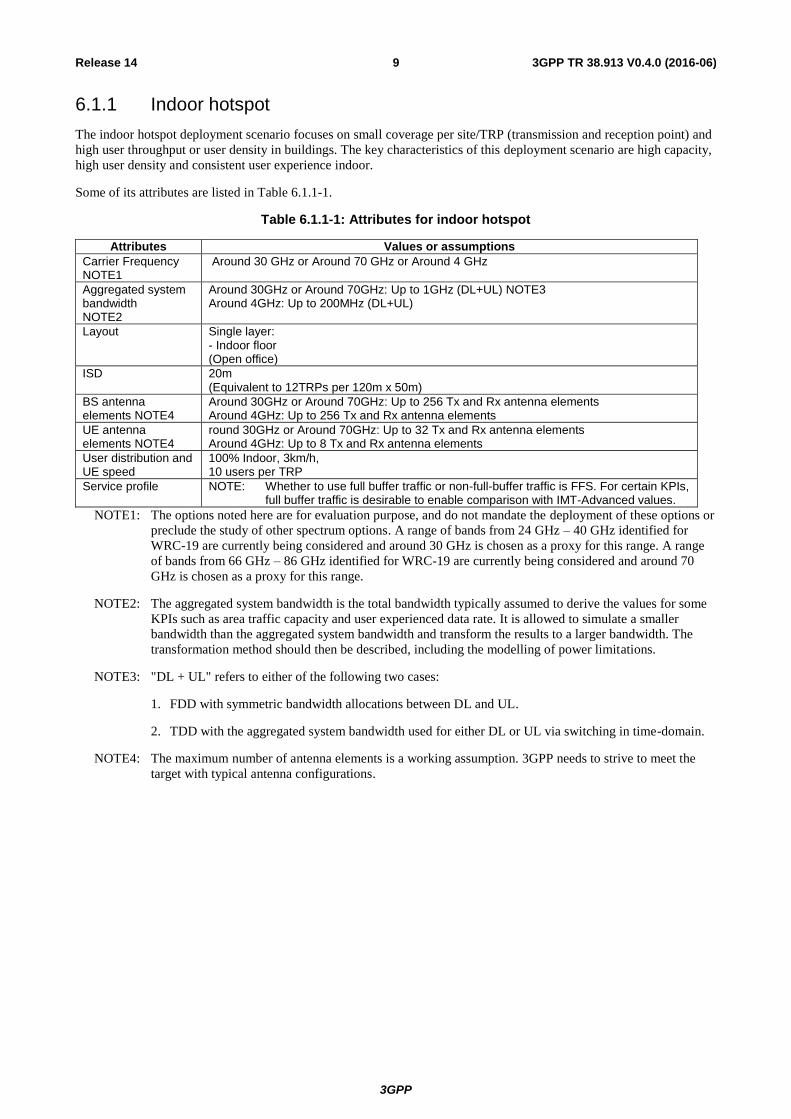
6.1.1 Indoor hotspot
The indoor hotspot deployment scenario focuses on small coverage per site/TRP (transmission and reception point) and
high user throughput or user density in buildings. The key characteristics of this deployment scenario are high capacity,
high user density and consistent user experience indoor.
Some of its attributes are listed in Table 6.1.1-1.
Table 6.1.1-1: Attributes for indoor hotspot
Attributes Values or assumptions
Carrier Frequency NOTE1
Around 30 GHz or Around 70 GHz or Around 4 GHz
Aggregated system bandwidth NOTE2
Around 30GHz or Around 70GHz: Up to 1GHz (DL+UL) NOTE3 Around 4GHz: Up to 200MHz (DL+UL)
Layout Single layer: - Indoor floor (Open office)
ISD 20m (Equivalent to 12TRPs per 120m x 50m)
BS antenna elements NOTE4
Around 30GHz or Around 70GHz: Up to 256 Tx and Rx antenna elements Around 4GHz: Up to 256 Tx and Rx antenna elements
UE antenna elements NOTE4
round 30GHz or Around 70GHz: Up to 32 Tx and Rx antenna elements Around 4GHz: Up to 8 Tx and Rx antenna elements
User distribution and UE speed
100% Indoor, 3km/h, 10 users per TRP
Service profile NOTE: Whether to use full buffer traffic or non-full-buffer traffic is FFS. For certain KPIs, full buffer traffic is desirable to enable comparison with IMT-Advanced values.
NOTE1: The options noted here are for evaluation purpose, and do not mandate the deployment of these options or
preclude the study of other spectrum options. A range of bands from 24 GHz – 40 GHz identified for
WRC-19 are currently being considered and around 30 GHz is chosen as a proxy for this range. A range
of bands from 66 GHz – 86 GHz identified for WRC-19 are currently being considered and around 70
GHz is chosen as a proxy for this range.
NOTE2: The aggregated system bandwidth is the total bandwidth typically assumed to derive the values for some
KPIs such as area traffic capacity and user experienced data rate. It is allowed to simulate a smaller
bandwidth than the aggregated system bandwidth and transform the results to a larger bandwidth. The
transformation method should then be described, including the modelling of power limitations.
NOTE3: "DL + UL" refers to either of the following two cases:
1. FDD with symmetric bandwidth allocations between DL and UL.
2. TDD with the aggregated system bandwidth used for either DL or UL via switching in time-domain.
NOTE4: The maximum number of antenna elements is a working assumption. 3GPP needs to strive to meet the
target with typical antenna configurations.

3GPP
3GPP TR 38.913 V0.4.0 (2016-06) 10 Release 14
6.1.2 Dense urban
The dense urban microcellular deployment scenario focuses on macro TRPs with or without micro TRPs and high user
densities and traffic loads in city centres and dense urban areas. The key characteristics of this deployment scenario are
high traffic loads, outdoor and outdoor-to-indoor coverage. This scenario will be interference-limited, using macro
TRPs with or without micro TRPs. A continuous cellular layout and the associated interference shall be assumed.
Some of its attributes are listed in Table 6.1.2-1.
Table 6.1.2-1: Attributes for dense urban
Attributes Values or assumptions
Carrier Frequency NOTE1
Around 4GHz + Around 30GHz (two layers)
Aggregated system bandwidth NOTE2
Around 30GHz: Up to1GHz (DL+UL) Around 4GHz: Up to 200MHz (DL+UL)
Layout Two layers: - Macro layer: Hex. Grid - Micro layer: Random drop Step 1 NOTE3: Around 4GHz in Macro layer Step 2 NOTE3: Both Around 4GHz & Around 30GHz may be available in Macro & Micro layers (including 1 macro layer, macro cell only)
ISD Macro layer: 200m Micro layer: 3micro TRPs per macro TRP NOTE4, All micro TRPs are all outdoor
BS antenna elements NOTE5
Around 30GHz: Up to 256 Tx and Rx antenna elements Around 4GHz: Up to 256 Tx and Rx antenna elements
UE antenna elements NOTE5
Around 30GHz: Up to 32 Tx and Rx antenna elements Around 4GHz: Up to 8 Tx and Rx antenna elements
User distribution and UE speed
Step1 NOTE3: Uniform/macro TRP, 10 users per TRP NOTE6, NOTE7
Step2 NOTE3: Uniform/macro TRP + Clustered/micro TRP, 10 users per TRP NoTE6,
NOTE7 80% indoor (3km/h), 20% outdoor (30km/h)
Service profile NOTE: Whether to use full buffer traffic or non-full-buffer traffic is FFS. For certain KPIs, full buffer traffic is desirable to enable comparison with IMT-Advanced values.
NOTE1: The options noted here are for evaluation purpose, and do not mandate the deployment of these options or
preclude the study of other spectrum options. A range of bands from 24 GHz – 40 GHz identified for
WRC-19 are currently being considered and around 30 GHz is chosen as a proxy for this range.
NOTE2: The aggregated system bandwidth is the total bandwidth typically assumed to derive the values for some
KPIs such as area traffic capacity and user experienced data rate. It is allowed to simulate a smaller
bandwidth than the aggregated system bandwidth and transform the results to a larger bandwidth. The
transformation method should then be described, including the modelling of power limitations.
NOTE3: Step 1 shall be used for the evaluation of spectral efficiency KPIs. Step2 shall be used for the evaluation
of the other deployment scenario dependant KPIs.
NOTE4: This value is the baseline and other number of micro TRPs per macro TRP (e.g., 6 or 10) is not precluded.
NOTE5: The maximum number of antenna elements is a working assumption. 3GPP needs to strive to meet the
target with typical antenna configurations.
NOTE6: 10 users per TRP is the baseline with full buffer traffic. 20 users per macro TRP with full buffer traffic is
not precluded.
NOTE7: Other number of users, number of TRPs and traffic models are FFS.
3GPP
3GPP TR 38.913 V0.4.0 (2016-06) 11 Release 14
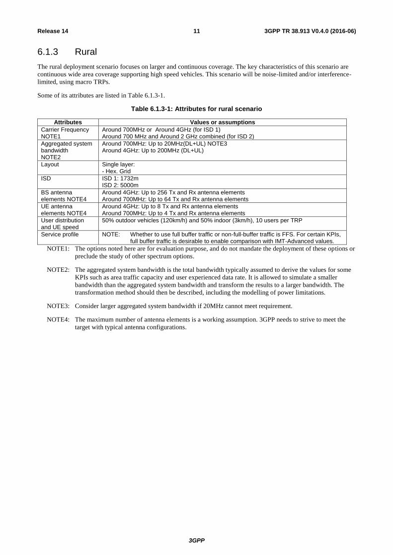
6.1.3 Rural
The rural deployment scenario focuses on larger and continuous coverage. The key characteristics of this scenario are
continuous wide area coverage supporting high speed vehicles. This scenario will be noise-limited and/or interference-
limited, using macro TRPs.
Some of its attributes are listed in Table 6.1.3-1.
Table 6.1.3-1: Attributes for rural scenario
Attributes Values or assumptions
Carrier Frequency NOTE1
Around 700MHz or Around 4GHz (for ISD 1) Around 700 MHz and Around 2 GHz combined (for ISD 2)
Aggregated system bandwidth NOTE2
Around 700MHz: Up to 20MHz(DL+UL) NOTE3 Around 4GHz: Up to 200MHz (DL+UL)
Layout Single layer: - Hex. Grid
ISD ISD 1: 1732m ISD 2: 5000m
BS antenna elements NOTE4
Around 4GHz: Up to 256 Tx and Rx antenna elements Around 700MHz: Up to 64 Tx and Rx antenna elements
UE antenna elements NOTE4
Around 4GHz: Up to 8 Tx and Rx antenna elements Around 700MHz: Up to 4 Tx and Rx antenna elements
User distribution and UE speed
50% outdoor vehicles (120km/h) and 50% indoor (3km/h), 10 users per TRP
Service profile NOTE: Whether to use full buffer traffic or non-full-buffer traffic is FFS. For certain KPIs, full buffer traffic is desirable to enable comparison with IMT-Advanced values.
NOTE1: The options noted here are for evaluation purpose, and do not mandate the deployment of these options or
preclude the study of other spectrum options.
NOTE2: The aggregated system bandwidth is the total bandwidth typically assumed to derive the values for some
KPIs such as area traffic capacity and user experienced data rate. It is allowed to simulate a smaller
bandwidth than the aggregated system bandwidth and transform the results to a larger bandwidth. The
transformation method should then be described, including the modelling of power limitations.
NOTE3: Consider larger aggregated system bandwidth if 20MHz cannot meet requirement.
NOTE4: The maximum number of antenna elements is a working assumption. 3GPP needs to strive to meet the
target with typical antenna configurations.
3GPP
3GPP TR 38.913 V0.4.0 (2016-06) 12 Release 14
6.1.4 Urban macro
The urban macro deployment scenario focuses on large cells and continuous coverage. The key characteristics of this
scenario are continuous and ubiquitous coverage in urban areas. This scenario will be interference-limited, using macro
TRPs (i.e. radio access points above rooftop level).
Some of its attributes are listed in Table 6.1.4-1.
Table 6.1.4-1: Attributes for urban macro
Attributes Values or assumptions
Carrier Frequency NOTE1
Around 2 GHz or Around 4 GHz or Around 30 GHz
Aggregated system bandwidth NOTE2
Around 4GHz: Up to 200 MHz (DL+UL) Around 30GHz: Up to 1GHz (DL+UL)
Layout Single layer: - Hex. Grid
ISD 500m
BS antenna elements NOTE3
Around 30GHz: Up to 256 Tx and Rx antenna elements Around 4GHz or Around 2GHz: Up to 256 Tx and Rx antenna elements
UE antenna elements NOTE3
Around 30GHz: Up to 32 Tx and Rx antenna elements Around 4GHz: Up to 8 Tx and Rx antenna elements
User distribution and UE speed
20% Outdoor in cars: 30km/h, 80% Indoor in houses: 3km/h 10 users per TRP NOTE4
Service profile NOTE: Whether to use full buffer traffic or non-full-buffer traffic is FFS. For certain KPIs, full buffer traffic is desirable to enable comparison with IMT-Advanced values.
NOTE1: The options noted here are for evaluation purpose, and do not mandate the deployment of these options or
preclude the study of other spectrum options. A range of bands from 24 GHz – 40 GHz identified for
WRC-19 are currently being considered and around 30 GHz is chosen as a proxy for this range.
NOTE2: The aggregated system bandwidth is the total bandwidth typically assumed to derive the values for some
KPIs such as area traffic capacity and user experienced data rate. It is allowed to simulate a smaller
bandwidth than the aggregated system bandwidth and transform the results to a larger bandwidth. The
transformation method should then be described, including the modelling of power limitations.
NOTE3: The maximum number of antenna elements is a working assumption. 3GPP needs to strive to meet the
target with typical antenna configurations.
NOTE4: 10 users per TRP is the baseline with full buffer traffic. 20 users per TRP with full buffer traffic is not
precluded.
Editor’s notes: User distribution is 80% indoor and 20% outdoor. Further refinement of outdoor user characteristics
being discussed.
3GPP
3GPP TR 38.913 V0.4.0 (2016-06) 13 Release 14
6.1.5 High speed
The high speed deployment scenario focuses on continuous coverage along track in high speed trains. The key
characteristics of this scenario are consistent user experience with very high mobility. In this deployment scenario,
dedicated linear deployment along railway line and the deployments including SFN scenarios captured in Section 6.2 of
[5] are considered, and UEs are located in train carriages. If the antenna of relay node for eNB-to-Relay is located at top
of one carriage of the train, the antenna of relay node for Relay-to-UE could be distributed to all carriages.
Some of its attributes are listed in Table 6.1.5-1.
Table 6.1.5-1: High Speed
Attributes Values or assumptions
Carrier Frequency NOTE1
Macro NOTE2 only: Around 4GHz Macro NOTE2+ relay nodes: 1) For BS to relay: Around 4 GHz For relay to UE: Around 30 GHz or Around 70 GH or Around 4 GHz 2) For BS to relay: Around 30 GHz For relay to UE: Around 30 GHz or Around 70 GHz or Around 4 GHz
Aggregated system bandwidth NOTE3
Around 4GHz: Up to 200 MHz (DL+UL) Around 30GHz or Around 70GHz: Up to 1GHz (DL+UL)
Layout Macro only:
Around 4GHz: Dedicated linear deployment along the railway line as in Figure 6.1.5-1. RRH site to railway track distance: 100m
Macro + relay nodes:
Around 4GHz: Dedicated linear deployment along the railway line as in Figure 6.1.5-1. RRH site to railway track distance: 100m
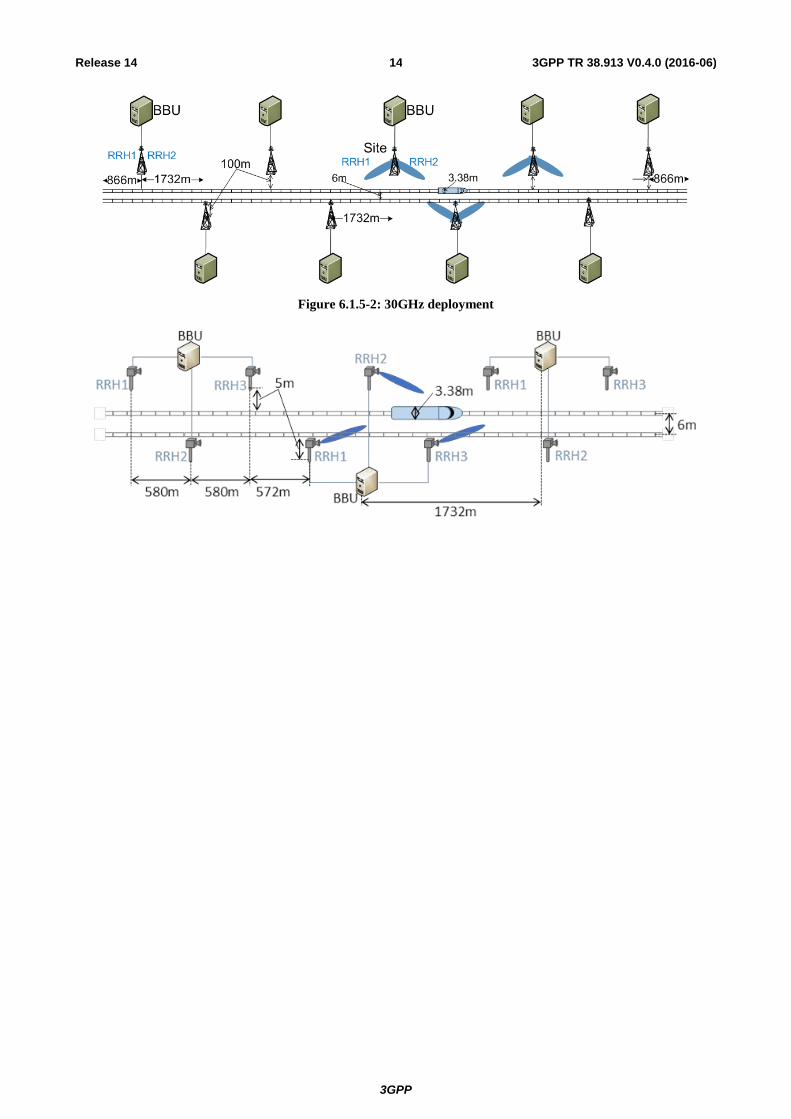
Around 30GHz: Dedicated linear deployment along the railway line as in Figure 6.1.5-2. RRH site to railway track distance: 5m.
ISD Around 4GHz: ISD 1732m between RRH sites, two TRPs per RRH site. See Figure 6.1.5-1.
Around 30GHz: 1732m between BBU sites, 3 RRH sites connected to 1 BBU, one TRP per RRH site, inter RRH site distance (580m, 580m, 572m). See Figure 6.1.5-2.
Small cell within carriages: ISD = 25m.
BS antenna elements NOTE4
Around 30GHz: Up to 256 Tx and Rx antenna elements Around 4GHz: Up to 256 Tx and Rx antenna elements
UE antenna elements NOTE4
Relay Tx: Up to 256 antenna elements Relay Rx: Up to 256 antenna elements Around 30GHz: Up to 32 Tx and Rx antenna elements Around 4GHz: Up to 8 Tx and Rx antenna elements
User distribution and UE speed
100% of users in train For non-full buffer, 300 UEs per macro cell (assuming 1000 passengers per high-speed train and at least 10% activity ratio) Maximum mobility speed: 500km/h
Service profile Alt 1: Full buffer Alt 2: FTP model 1/2/3 with packet size 0.5 Mbytes, 0.1 Mbytes (other value is not precluded) Other traffic models are not precluded.
NOTE1: The options noted here are for evaluation purpose, and do not mandate the deployment of these options or
preclude the study of other spectrum options. A range of bands from 24 GHz – 40 GHz identified for
WRC-19 are currently being considered and around 30 GHz is chosen as a proxy for this range. A range
of bands from 66 GHz – 86 GHz identified for WRC-19 are currently being considered and around 70
GHz is chosen as a proxy for this range
NOTE2: For Macro, it is assumed RRH sharing the same cell ID or having different cell ID.
NOTE3: The aggregated system bandwidth is the total bandwidth typically assumed to derive the values for some
KPIs such as area traffic capacity and user experienced data rate. It is allowed to simulate a smaller
bandwidth than the aggregated system bandwidth and transform the results to a larger bandwidth. The
transformation method should then be described, including the modelling of power limitations.
NOTE4: The maximum number of antenna elements is a working assumption. 3GPP needs to strive to meet the
target with typical antenna configurations.
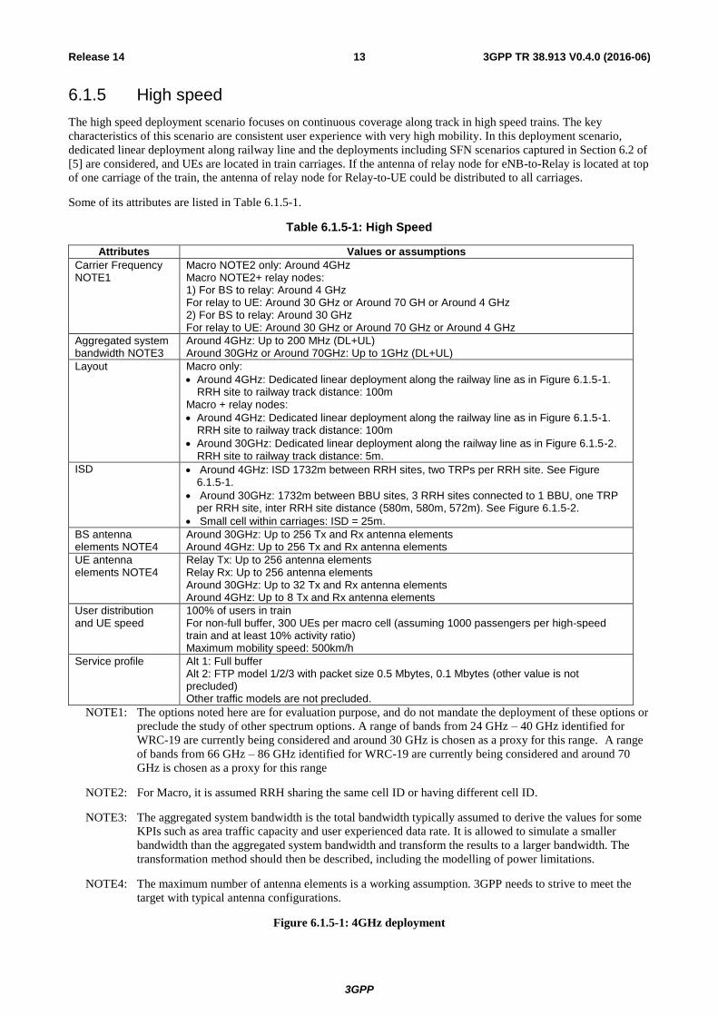
Figure 6.1.5-1: 4GHz deployment
3GPP
3GPP TR 38.913 V0.4.0 (2016-06) 14 Release 14
Figure 6.1.5-2: 30GHz deployment
3GPP
3GPP TR 38.913 V0.4.0 (2016-06) 15 Release 14
6.1.6 Extreme long distance coverage in low density areas
The extreme Long Range deployment scenario is defined to allow for the Provision of services for very large areas with
low density of users whether they are humans and machines (e.g. Low ARPU regions, wilderness, areas where only
highways are located, etc). The key characteristics of this scenario are Macro cells with very large area coverage
supporting basic data speeds and voice services, with low to moderate user throughput and low user density.
Table 6.1.6-1: Attributes for extreme rural
Attributes Values or assumptions
Carrier Frequency Below 3 GHz With a priority on bands below 1GHz Around 700 MHz
System Bandwidth 40 MHz (DL+UL)
Layout Single layer: Isolated Macro cells
Cell range 100 km range (Isolated cell) to be evaluated through system level simulations. Feasibility of Higher Range shall be evaluated through Link level evaluation (for example in some scenarios ranges up to 150-300km may be required).
User density and UE speed
User density: NOTE1 Speed up to 160 km/h
Traffic model Average data throughput at busy hours/user: 30 kbps User experienced data rate: up to 2 Mbps DL while stationary and 384 kbps DL while moving NOTE2
NOTE1: Evaluate how many users can be served per cell site when the range edge users are serviced with the
target user experience data rate.
NOTE2: Target values for UL are lower than DL, 1/3 of DL is desirable.
3GPP
3GPP TR 38.913 V0.4.0 (2016-06) 16 Release 14
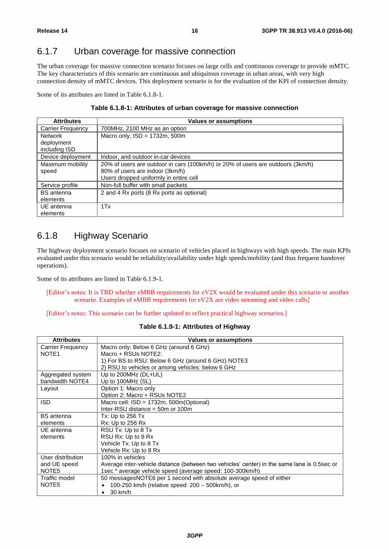
6.1.7 Urban coverage for massive connection
The urban coverage for massive connection scenario focuses on large cells and continuous coverage to provide mMTC.
The key characteristics of this scenario are continuous and ubiquitous coverage in urban areas, with very high
connection density of mMTC devices. This deployment scenario is for the evaluation of the KPI of connection density.
Some of its attributes are listed in Table 6.1.8-1.
Table 6.1.8-1: Attributes of urban coverage for massive connection
Attributes Values or assumptions
Carrier Frequency 700MHz, 2100 MHz as an option
Network deployment including ISD
Macro only, ISD = 1732m, 500m
Device deployment Indoor, and outdoor in-car devices
Maximum mobility speed
20% of users are outdoor in cars (100km/h) or 20% of users are outdoors (3km/h) 80% of users are indoor (3km/h) Users dropped uniformly in entire cell
Service profile Non-full buffer with small packets
BS antenna elements
2 and 4 Rx ports (8 Rx ports as optional)
UE antenna elements
1Tx
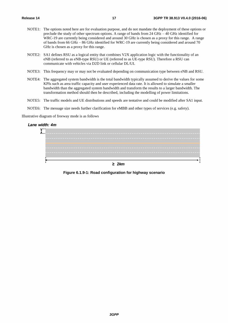
6.1.8 Highway Scenario
The highway deployment scenario focuses on scenario of vehicles placed in highways with high speeds. The main KPIs
evaluated under this scenario would be reliability/availability under high speeds/mobility (and thus frequent handover
operations).
Some of its attributes are listed in Table 6.1.9-1.
[Editor’s notes: It is TBD whether eMBB requirements for eV2X would be evaluated under this scenario or another
scenario. Examples of eMBB requirements for eV2X are video streaming and video calls]
[Editor’s notes: This scenario can be further updated to reflect practical highway scenarios.]
Table 6.1.9-1: Attributes of Highway
Attributes Values or assumptions
Carrier Frequency NOTE1
Macro only: Below 6 GHz (around 6 GHz) Macro + RSUs NOTE2: 1) For BS to RSU: Below 6 GHz (around 6 GHz) NOTE3 2) RSU to vehicles or among vehicles: below 6 GHz
Aggregated system bandwidth NOTE4
Up to 200MHz (DL+UL) Up to 100MHz (SL)
Layout Option 1: Macro only Option 2: Macro + RSUs NOTE2
ISD Macro cell: ISD = 1732m, 500m(Optional) Inter-RSU distance = 50m or 100m
BS antenna elements
Tx: Up to 256 Tx Rx: Up to 256 Rx
UE antenna elements
RSU Tx: Up to 8 Tx RSU Rx: Up to 8 Rx Vehicle Tx: Up to 8 Tx Vehicle Rx: Up to 8 Rx
User distribution and UE speed NOTE5
100% in vehicles Average inter-vehicle distance (between two vehicles’ center) in the same lane is 0.5sec or 1sec * average vehicle speed (average speed: 100-300km/h)
Traffic model NOTE5
50 messagesNOTE6 per 1 second with absolute average speed of either
100-250 km/h (relative speed: 200 – 500km/h), or
30 km/h
3GPP
3GPP TR 38.913 V0.4.0 (2016-06) 17 Release 14
NOTE1: The options noted here are for evaluation purpose, and do not mandate the deployment of these options or
preclude the study of other spectrum options. A range of bands from 24 GHz – 40 GHz identified for
WRC-19 are currently being considered and around 30 GHz is chosen as a proxy for this range. A range
of bands from 66 GHz – 86 GHz identified for WRC-19 are currently being considered and around 70
GHz is chosen as a proxy for this range.
NOTE2: SA1 defines RSU as a logical entity that combines V2X application logic with the functionality of an
eNB (referred to as eNB-type RSU) or UE (referred to as UE-type RSU). Therefore a RSU can
communicate with vehicles via D2D link or cellular DL/UL
NOTE3: This frequency may or may not be evaluated depending on communication type between eNB and RSU.
NOTE4: The aggregated system bandwidth is the total bandwidth typically assumed to derive the values for some
KPIs such as area traffic capacity and user experienced data rate. It is allowed to simulate a smaller
bandwidth than the aggregated system bandwidth and transform the results to a larger bandwidth. The
transformation method should then be described, including the modelling of power limitations.
NOTE5: The traffic models and UE distributions and speeds are tentative and could be modified after SA1 input.
NOTE6: The message size needs further clarification for eMBB and other types of services (e.g. safety).
Illustrative diagram of freeway mode is as follows
Lane width: 4m
≥ 2km
Figure 6.1.9-1: Road configuration for highway scenario
3GPP
3GPP TR 38.913 V0.4.0 (2016-06) 18 Release 14
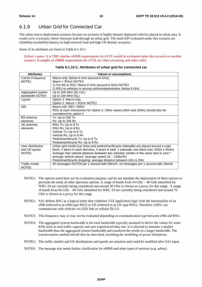
6.1.9 Urban Grid for Connected Car
The urban macro deployment scenario focuses on scenario of highly densely deployed vehicles placed in urban area. It
could cover a scenario where freeways lead through an urban grid. The main KPI evaluated under this scenario are
reliability/availability/latency in high network load and high UE density scenarios.
Some of its attributes are listed in Table 6.1.10-1.
[Editor’s notes: It is TBD whether eMBB requirements for eV2X would be evaluated under this scenario or another
scenario. Examples of eMBB requirements for eV2X are video streaming and video calls]
Table 6.1.10-1: Attributes of urban grid for connected car
Attributes Values or assumptions
Carrier Frequency NOTE1
Macro only: Below 6 GHz (around 6 GHz) Macro + RSUs NOTE2: 1) For BS to RSU: Below 6 GHz (around 6 GHz) NOTE3 2) RSU to vehicles or among vehicles/pedestrians: below 6 GHz
Aggregated system bandwidth NOTE4
Up to 200 MHz (DL+UL) Up to 100 MHz (SL)
Layout Option 1: Macro only Option 2: Macro + RSUs NOTE2
ISD Macro cell: ISD = 500m RSU at each intersection for Option 2. Other values (50m and 100m) should also be considered for option 2
BS antenna elements
Tx: Up to 256 Tx Rx: Up to 256 Rx
UE antenna elements
RSU Tx: Up to 8 Tx RSU Rx: Up to 8 Rx Vehicle Tx: Up to 8 Tx Vehicle Rx: Up to 8 Rx Pedestrian/bicycle Tx: Up to 8 Tx Pedestrian/bicycle Rx: Up to 8 Rx
User distribution and UE speed NOTE5
Urban grid model (car lanes and pedestrian/bicycle sidewalks are placed around a road block. 2 lanes in each direction, 4 lanes in total, 1 sidewalk, one block size: 433m x 250m) Average inter-vehicle distance (between two vehicles’ center) in the same lane is 1sec * average vehicle speed (average speed 15 – 120km/h) Pedestrian/bicycle dropping: average distance between UEs is 20m
Traffic model NOTE5
50 messages NOTE6 per 1 second with 60km/h, 10 messages per 1 second with 15km/h
NOTE1: The options noted here are for evaluation purpose, and do not mandate the deployment of these options or
preclude the study of other spectrum options. A range of bands from 24 GHz – 40 GHz identified for
WRC-19 are currently being considered and around 30 GHz is chosen as a proxy for this range. A range
of bands from 66 GHz – 86 GHz identified for WRC-19 are currently being considered and around 70
GHz is chosen as a proxy for this range
NOTE2: SA1 defines RSU as a logical entity that combines V2X application logic with the functionality of an
eNB (referred to as eNB-type RSU) or UE (referred to as UE-type RSU). Therefore a RSU can
communicate with vehicles via D2D link or cellular DL/UL
NOTE3: This frequency may or may not be evaluated depending on communication type between eNB and RSU.
NOTE4: The aggregated system bandwidth is the total bandwidth typically assumed to derive the values for some
KPIs such as area traffic capacity and user experienced data rate. It is allowed to simulate a smaller
bandwidth than the aggregated system bandwidth and transform the results to a larger bandwidth. The
transformation method should then be described, including the modelling of power limitations.
NOTE5: The traffic models and UE distributions and speeds are tentative and could be modified after SA1 input.
NOTE6: The message size needs further clarification for eMBB and other types of services (e.g. safety).
3GPP
3GPP TR 38.913 V0.4.0 (2016-06) 19 Release 14
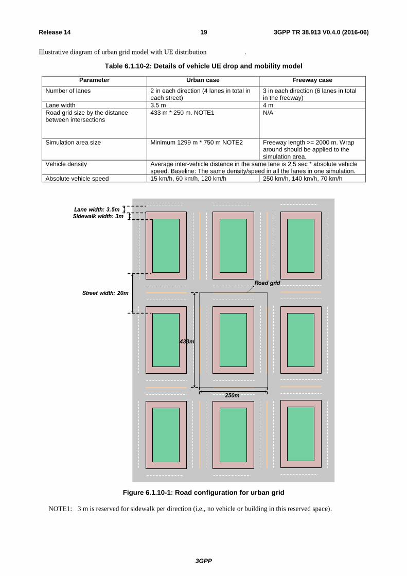
Illustrative diagram of urban grid model with UE distribution is as follows:.
Table 6.1.10-2: Details of vehicle UE drop and mobility model
Parameter Urban case Freeway case
Number of lanes 2 in each direction (4 lanes in total in each street)
3 in each direction (6 lanes in total in the freeway)
Lane width 3.5 m 4 m
Road grid size by the distance between intersections
433 m * 250 m. NOTE1 N/A
Simulation area size Minimum 1299 m * 750 m NOTE2 Freeway length >= 2000 m. Wrap around should be applied to the simulation area.
Vehicle density Average inter-vehicle distance in the same lane is 2.5 sec * absolute vehicle speed. Baseline: The same density/speed in all the lanes in one simulation.
Absolute vehicle speed 15 km/h, 60 km/h, 120 km/h 250 km/h, 140 km/h, 70 km/h
Lane width: 3.5m
Sidewalk width: 3m
Street width: 20m
433m
250m
Road grid
Figure 6.1.10-1: Road configuration for urban grid
NOTE1: 3 m is reserved for sidewalk per direction (i.e., no vehicle or building in this reserved space).
NOTE2: This value is tentative and could be modified after SA1 input.
3GPP
3GPP TR 38.913 V0.4.0 (2016-06) 20 Release 14
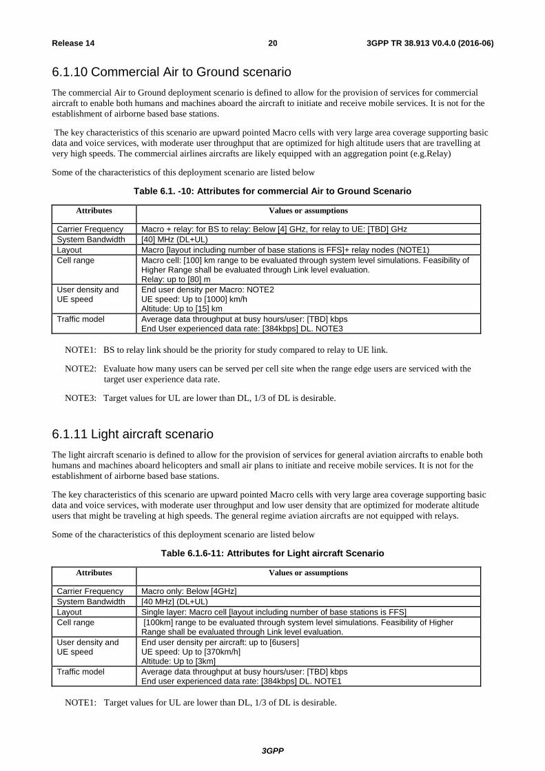
6.1.10 Commercial Air to Ground scenario
The commercial Air to Ground deployment scenario is defined to allow for the provision of services for commercial
aircraft to enable both humans and machines aboard the aircraft to initiate and receive mobile services. It is not for the
establishment of airborne based base stations.
The key characteristics of this scenario are upward pointed Macro cells with very large area coverage supporting basic
data and voice services, with moderate user throughput that are optimized for high altitude users that are travelling at
very high speeds. The commercial airlines aircrafts are likely equipped with an aggregation point (e.g.Relay)
Some of the characteristics of this deployment scenario are listed below
Table 6.1. -10: Attributes for commercial Air to Ground Scenario
Attributes Values or assumptions
Carrier Frequency Macro + relay: for BS to relay: Below [4] GHz, for relay to UE: [TBD] GHz
System Bandwidth [40] MHz (DL+UL)
Layout Macro [layout including number of base stations is FFS]+ relay nodes (NOTE1)
Cell range Macro cell: [100] km range to be evaluated through system level simulations. Feasibility of Higher Range shall be evaluated through Link level evaluation. Relay: up to [80] m
User density and UE speed
End user density per Macro: NOTE2 UE speed: Up to [1000] km/h Altitude: Up to [15] km
Traffic model Average data throughput at busy hours/user: [TBD] kbps End User experienced data rate: [384kbps] DL. NOTE3
NOTE1: BS to relay link should be the priority for study compared to relay to UE link.
NOTE2: Evaluate how many users can be served per cell site when the range edge users are serviced with the
target user experience data rate.
NOTE3: Target values for UL are lower than DL, 1/3 of DL is desirable.
6.1.11 Light aircraft scenario
The light aircraft scenario is defined to allow for the provision of services for general aviation aircrafts to enable both
humans and machines aboard helicopters and small air plans to initiate and receive mobile services. It is not for the
establishment of airborne based base stations.
The key characteristics of this scenario are upward pointed Macro cells with very large area coverage supporting basic
data and voice services, with moderate user throughput and low user density that are optimized for moderate altitude
users that might be traveling at high speeds. The general regime aviation aircrafts are not equipped with relays.
Some of the characteristics of this deployment scenario are listed below
Table 6.1.6-11: Attributes for Light aircraft Scenario
Attributes Values or assumptions
Carrier Frequency Macro only: Below [4GHz]
System Bandwidth [40 MHz] (DL+UL)
Layout Single layer: Macro cell [layout including number of base stations is FFS]
Cell range [100km] range to be evaluated through system level simulations. Feasibility of Higher Range shall be evaluated through Link level evaluation.
User density and UE speed
End user density per aircraft: up to [6users] UE speed: Up to [370km/h] Altitude: Up to [3km]
Traffic model Average data throughput at busy hours/user: [TBD] kbps End user experienced data rate: [384kbps] DL. NOTE1
NOTE1: Target values for UL are lower than DL, 1/3 of DL is desirable.
3GPP
3GPP TR 38.913 V0.4.0 (2016-06) 21 Release 14
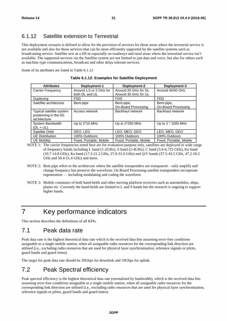
6.1.12 Satellite extension to Terrestrial
This deployment scenario is defined to allow for the provision of services for those areas where the terrestrial service is
not available and also for those services that can be more efficiently supported by the satellite systems such as
broadcasting service. Satellite acts as a fill-in especially on roadways and rural areas where the terrestrial service isn’t
available. The supported services via the Satellite system are not limited to just data and voice, but also for others such
as machine type communications, broadcast and other delay tolerant services.
Some of its attributes are listed in Table 6.1.12
Table 6.1.12: Examples for Satellite Deployment
Attributes Deployment-1 Deployment-2 Deployment-3
Carrier Frequency Around 1.5 or 2 GHz for both DL and UL
Around 20 GHz for DL Around 30 GHz for UL
Around 40/50 GHz
Duplexing FDD FDD FDD
Satellite architecture Bent-pipe Bent-pipe, On-Board Processing
Bent-pipe, On-Board Processing
Typical satellite system positioning in the 5G architecture
Access network Backhaul network Backhaul network
System Bandwidth (DL + UL)
Up to 2*10 MHz Up to 2*250 MHz Up to 2 * 1000 MHz
Satellite Orbit GEO, LEO LEO, MEO, GEO LEO, MEO, GEO
UE Distribution 100% Outdoors 100% Outdoors 100% Outdoors
UE Mobility Fixed, Portable, Mobile Fixed, Portable, Mobile Fixed, Portable, Mobile
NOTE 1: The carrier frequencies noted here are for evaluation purpose only, satellites are deployed in wide range
of frequency bands including L band (1-2GHz), S band (2-4GHz), C band (3.4-6.725 GHz), Ku band
(10.7-14.8 GHz), Ka band (17.3-21.2 GHz, 27.0-31.0 GHz) and Q/V bands (37.5-43.5 GHz, 47.2-50.2
GHz and 50.4-51.4 GHz) and more.
NOTE 2: Bent pipe refers to the architecure where the satellite transponders are transparent—only amplify and
change frequency but preserve the waveform. On Board Processing satellite transponders incorperate
regeneration — including modulating and coding the waveform
NOTE 3: Mobile consitutes of both hand-helds and other moving platform receivers such as automobiles, ships,
planes etc. Currently the hand-helds are limited to L and S bands but the research is ongoing to support
higher bands.
7 Key performance indicators
This section describes the definitions of all KPIs.
7.1 Peak data rate
Peak data rate is the highest theoretical data rate which is the received data bits assuming error-free conditions
assignable to a single mobile station, when all assignable radio resources for the corresponding link direction are
utilised (i.e., excluding radio resources that are used for physical layer synchronisation, reference signals or pilots,
guard bands and guard times).
The target for peak data rate should be 20Gbps for downlink and 10Gbps for uplink.
7.2 Peak Spectral efficiency
Peak spectral efficiency is the highest theoretical data rate (normalised by bandwidth), which is the received data bits
assuming error-free conditions assignable to a single mobile station, when all assignable radio resources for the
corresponding link direction are utilised (i.e., excluding radio resources that are used for physical layer synchronisation,
reference signals or pilots, guard bands and guard times).

3GPP
3GPP TR 38.913 V0.4.0 (2016-06) 22 Release 14
The target for peak spectral efficiency should be 30bps/Hz for downlink and 15bps/Hz for uplink.
Higher frequency bands could have higher bandwidth but lower spectral efficiency and lower frequency bands could
have lower bandwidth but higher spectral efficiency. Thus, peak data rate cannot be directly derived from peak spectral
efficiency and bandwidth multiplication.
7.3 Bandwidth
Bandwidth means the maximal aggregated total system bandwidth. It may be supported by single or multiple RF
carriers.
Quantitative KPI
[Editor’s note: This is an ITU-R requirement from IMT-Advanced. It may not be up to 3GPP to set a value for this
requirement.]
7.4 Control plane latency
Control plane latency refers to the time to move from a battery efficient state (e.g., IDLE) to start of continuous data
transfer (e.g., ACTIVE).
The target for control plane latency should be 10ms.
NOTE1: For satellite communications link, the control plane should be able to support RTT of up to 600ms in the
case of GEO and HEO, up to 180ms in the case of MEO, and up to 50ms in the case of LEO satellite
systems.
7.5 User plane latency
The time it takes to successfully deliver an application layer packet/message from the radio protocol layer 2/3 SDU
ingress point to the radio protocol layer 2/3 SDU egress point via the radio interface in both uplink and downlink
directions, where neither device nor Base Station reception is restricted by DRX.
For URLLC the target for user plane latency should be 0.5ms for UL, and 0.5ms for DL. Furthermore, if possible, the
latency should also be low enough to support the use of the next generation access technologies as a wireless transport
technology that can be used within the next generation access architecture.
NOTE1: The reliability KPI also provides a latency value with an associated reliability requirement. The value
above should be considered an average value and does not have an associated high reliability
requirement.
For eMBB, the target for user plane latency should be 4ms for UL, and 4ms for DL.
NOTE2: For eMBB value, the evaluation needs to consider all typical delays associated with the transfer of the
data packets in an efficient way (e.g. applicable procedural delay when resources are not preallocated,
averaged HARQ retransmission delay, impacts of network architecture).
When a satellite link is involved in the communication with a user equipment, the target for user plane RTT can be as
high as 600ms for GEO satellite systems, up to 180ms for MEO satellite systems, and up to 50ms for LEO satellite
systems.
NOTE3: For the satellite case, the evaluation needs to consider the max RTT that is associated with the GEO
satellite systems.
7.6 Latency for infrequent small packets
For infrequent application layer small packet/message transfer, the time it takes to successfully deliver an application
layer packet/message from the radio protocol layer 2/3 SDU ingress point at the mobile device to the radio protocol
layer 2/3 SDU egress point in the RAN, when the mobile device starts from its most "battery efficient" state.
For the definition above, the latency shall be no worse than 10 seconds on the uplink for a 20 byte application packet
(with uncompressed IP header corresponding to 105 bytes physical layer) measured at the maximum MCL (164dB).
3GPP
3GPP TR 38.913 V0.4.0 (2016-06) 23 Release 14
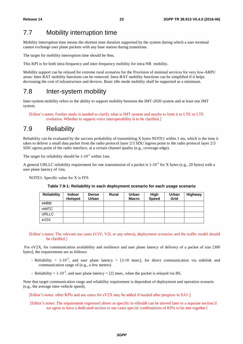
7.7 Mobility interruption time
Mobility interruption time means the shortest time duration supported by the system during which a user terminal
cannot exchange user plane packets with any base station during transitions.
The target for mobility interruption time should be 0ms.
This KPI is for both intra-frequency and inter-frequency mobility for intra-NR mobility.
Mobility support can be relaxed for extreme rural scenarios for the Provision of minimal services for very low-ARPU
areas: Inter RAT mobility functions can be removed. Intra-RAT mobility functions can be simplified if it helps
decreasing the cost of infrastructure and devices. Basic idle mode mobility shall be supported as a minimum.
7.8 Inter-system mobility
Inter-system mobility refers to the ability to support mobility between the IMT-2020 system and at least one IMT
system.
[Editor’s notes: Further study is needed to clarify what is IMT system and maybe to limit it to LTE or LTE
evolution. Whether to support voice interoperability is to be clarified.]
7.9 Reliability
Reliability can be evaluated by the success probability of transmitting X bytes NOTE1 within 1 ms, which is the time it
takes to deliver a small data packet from the radio protocol layer 2/3 SDU ingress point to the radio protocol layer 2/3
SDU egress point of the radio interface, at a certain channel quality (e.g., coverage-edge).
The target for reliability should be 1-10-5
within 1ms.
A general URLLC reliability requirement for one transmission of a packet is 1-10-5
for X bytes (e.g., 20 bytes) with a
user plane latency of 1ms.
NOTE1: Specific value for X is FFS
Table 7.9-1: Reliability in each deployment scenario for each usage scenario
Reliability Indoor Hotspot
Dense Urban
Rural Urban Macro
High Speed
Urban Grid
Highway
eMBB
mMTC
URLLC
eV2X
[Editor’s notes: The relevant use cases (V2V, V2I, or any others), deployment scenarios and the traffic model should
be clarified.]
For eV2X, for communication availability and resilience and user plane latency of delivery of a packet of size [300
bytes], the requirements are as follows:
- Reliability = 1-10-5
, and user plane latency = [3-10 msec], for direct communication via sidelink and
communication range of (e.g., a few meters)
- Reliability = 1-10-5
, and user plane latency = [2] msec, when the packet is relayed via BS.
Note that target communication range and reliability requirement is dependent of deployment and operation scenario
(e.g., the average inter-vehicle speed).
[Editor’s notes: other KPIs and use cases for eV2X may be added if needed after progress in SA1.]
[Editor’s notes: The requirement expressed above as specific to eHealth can be moved later to a separate section if
we agree to have a dedicated section to use cases special combinations of KPIs to be met together]

3GPP
3GPP TR 38.913 V0.4.0 (2016-06) 24 Release 14
7.10 Coverage
"Maximum coupling loss" (MCL) in uplink and downlink between device and Base Station site (antenna connector(s))
for a data rate of 160bps, where the data rate is observed at the egress/ingress point of the radio protocol stack in uplink
and downlink.
The target for coverage should be 164dB.
7.10.1 Extreme Coverage
The coupling loss is defined as the total long-term channel loss over the link between the UE antenna ports and the
eNodeB antenna ports, and includes in practice antenna gains, path loss, shadowing, body loss, etc. The maximum
coupling loss (MCL) is the limit value of the coupling loss at which the service can be delivered, and therefore defines
the coverage of the service. The MCL is independent of the carrier frequency. It is defined in the UL and DL as:
- UL MCL = UL Max Tx power - eNB Sensitivity
- DL MCL = DL Max Tx power - UE Sensitivity
The MCL is evaluated via link budget analysis (supported by link level simulations). The proposed MCL calculation
template is given in following table 7.10.1-1:
Table 7.10.1-1: MCL calculation template
Physical channel name Value
Transmitter
(1) Tx power (dBm)
Receiver
(2) Thermal noise density (dBm/Hz)
(3) Receiver noise figure (dB)
(4) Interference margin (dB)
(5) Occupied channel bandwidth (Hz)
(6) Effective noise power = (2) + (3) + (4) + 10 log(5) (dBm)
(7) Required SINR (dB)
(8) Receiver sensitivity = (6) + (7) (dBm)
(9) MCL = (1) - (8) (dB)
The following assumptions are used:
UE Tx power 23dBm
DL Tx power 46dBm
Antenna configuration eNB TBD
Antenna configuration UE TBD
eNB receiver noise figure 5dB
UE receiver noise figure 9dB
Interference margin 0dB
3GPP
3GPP TR 38.913 V0.4.0 (2016-06) 25 Release 14
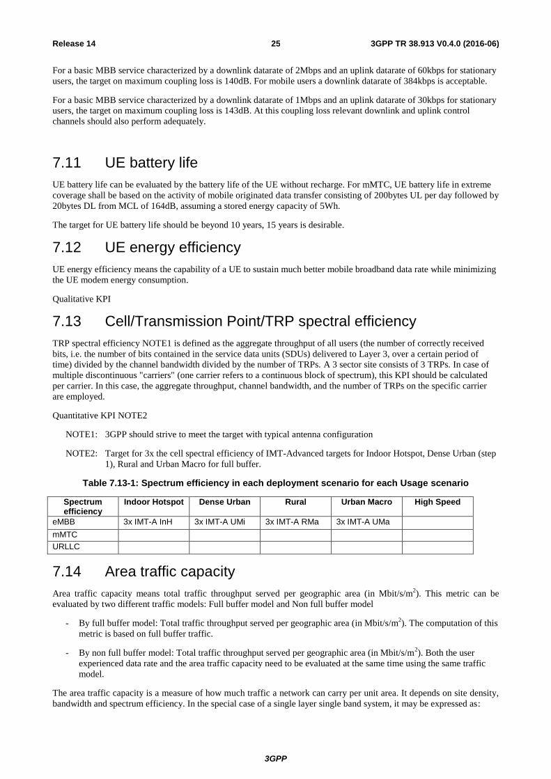
For a basic MBB service characterized by a downlink datarate of 2Mbps and an uplink datarate of 60kbps for stationary
users, the target on maximum coupling loss is 140dB. For mobile users a downlink datarate of 384kbps is acceptable.
For a basic MBB service characterized by a downlink datarate of 1Mbps and an uplink datarate of 30kbps for stationary
users, the target on maximum coupling loss is 143dB. At this coupling loss relevant downlink and uplink control
channels should also perform adequately.
7.11 UE battery life
UE battery life can be evaluated by the battery life of the UE without recharge. For mMTC, UE battery life in extreme
coverage shall be based on the activity of mobile originated data transfer consisting of 200bytes UL per day followed by
20bytes DL from MCL of 164dB, assuming a stored energy capacity of 5Wh.
The target for UE battery life should be beyond 10 years, 15 years is desirable.
7.12 UE energy efficiency
UE energy efficiency means the capability of a UE to sustain much better mobile broadband data rate while minimizing
the UE modem energy consumption.
Qualitative KPI
7.13 Cell/Transmission Point/TRP spectral efficiency
TRP spectral efficiency NOTE1 is defined as the aggregate throughput of all users (the number of correctly received
bits, i.e. the number of bits contained in the service data units (SDUs) delivered to Layer 3, over a certain period of
time) divided by the channel bandwidth divided by the number of TRPs. A 3 sector site consists of 3 TRPs. In case of
multiple discontinuous "carriers" (one carrier refers to a continuous block of spectrum), this KPI should be calculated
per carrier. In this case, the aggregate throughput, channel bandwidth, and the number of TRPs on the specific carrier
are employed.
Quantitative KPI NOTE2
NOTE1: 3GPP should strive to meet the target with typical antenna configuration
NOTE2: Target for 3x the cell spectral efficiency of IMT-Advanced targets for Indoor Hotspot, Dense Urban (step
1), Rural and Urban Macro for full buffer.
Table 7.13-1: Spectrum efficiency in each deployment scenario for each Usage scenario
Spectrum efficiency
Indoor Hotspot Dense Urban Rural Urban Macro High Speed
eMBB 3x IMT-A InH 3x IMT-A UMi 3x IMT-A RMa 3x IMT-A UMa
mMTC
URLLC
7.14 Area traffic capacity
Area traffic capacity means total traffic throughput served per geographic area (in Mbit/s/m2). This metric can be
evaluated by two different traffic models: Full buffer model and Non full buffer model
- By full buffer model: Total traffic throughput served per geographic area (in Mbit/s/m2). The computation of this
metric is based on full buffer traffic.
- By non full buffer model: Total traffic throughput served per geographic area (in Mbit/s/m2). Both the user
experienced data rate and the area traffic capacity need to be evaluated at the same time using the same traffic
model.
The area traffic capacity is a measure of how much traffic a network can carry per unit area. It depends on site density,
bandwidth and spectrum efficiency. In the special case of a single layer single band system, it may be expressed as:
3GPP
3GPP TR 38.913 V0.4.0 (2016-06) 26 Release 14
area capacity (bps/m2) = site density (site/m
2) × bandwidth (Hz) × spectrum efficiency (bps/Hz/site) NOTE1
NOTE1: Results of TRP spectral efficiency for non-full buffer are also provided separately.
In order to improve area traffic capacity, 3GPP can develop standards with means for high spectrum efficiency. To this
end, spectrum efficiency gains in the order of three times IMT-Advanced are targeted. Furthermore, 3GPP can develop
standards with means for large bandwidth support. To this end, it is proposed that at least 1GHz aggregated bandwidth
shall be supported.
The available bandwidth and site density NOTE2, which both have a direct impact on the available area capacity, are
however not under control of 3GPP.
NOTE2: Site here refers to single transmission and reception point (TRP).
Based on this, it is proposed to use the spectrum efficiency results together with assumptions on available bandwidth
and site density in order to derive a quantitative area traffic capacity KPI for information.
7.15 User experienced data rate
User experienced data rate NOTE1 can be evaluated for non-full buffer traffic and for full buffer traffic.
NOTE1: Non-full buffer simulations are preferred for the evaluation of this KPI.
For non-full buffer traffic, user experienced data rate is the 5%-percentile (5%) of the user throughput. User throughput
(during active time) is defined as the size of a burst divided by the time between the arrival of the first packet of a burst
and the reception of the last packet of the burst.
The target values for the user experienced data rate are associated with non-full buffer evaluation. The non-full buffer
user experienced data rate target is applicable at the non-full buffer area traffic capacity traffic level.
For full buffer traffic, user experienced data rate is calculated as:
user experienced data rate = 5% user spectrum efficiency × bandwidth
Here it should be noted that the 5% user spectrum efficiency depends on the number of active users sharing the channel
(assumed to be 10 in the ITU evaluations [4]), and that the 5% user spectrum efficiency for a fixed transmit power may
vary with bandwidth. To keep a high 5% user spectrum efficiency and a few users sharing the channel, a dense network
is beneficial, i.e. 5% user spectrum efficiency may vary also with site density(Site here refers to single transmission and
reception point (TRP).
To improve user experienced data rates, 3GPP can develop standards with means for high 5% user spectrum efficiency.
To this end, 5% user spectrum efficiency gains in the order of three times IMT-Advanced are proposed. Furthermore,
3GPP can develop standards with means for large bandwidth support. To this end, it is proposed that at least 1GHz
aggregated bandwidth shall be supported.
The available bandwidth and site density, which both have a strong impact on the available user experienced data rates,
are however not under control of 3GPP.
Based on this, the full buffer experienced user data rate is evaluated for information without numerical requirements.
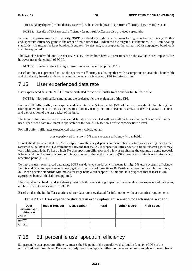
Table 7.15-1: User experience data rate in each deployment scenario for each usage scenario
User experienced
data rate
Indoor Hotspot Dense Urban Rural Urban Macro High Speed
eMBB
mMTC
URLLC
7.16 5th percentile user spectrum efficiency
5th percentile user spectrum efficiency means the 5% point of the cumulative distribution function (CDF) of the
normalized user throughput. The (normalized) user throughput is defined as the average user throughput (the number of
3GPP
3GPP TR 38.913 V0.4.0 (2016-06) 27 Release 14
correctly received bits by users, i.e., the number of bits contained in the SDU delivered to Layer 3, over a certain period
of time, divided by the channel bandwidth and is measured in bit/s/Hz. The channel bandwidth for this purpose is
defined as the effective bandwidth times the frequency reuse factor, where the effective bandwidth is the operating
bandwidth normalised appropriately considering the uplink/downlink ratio. In case of multiple discontinuous “carriers”
(one carrier refers to a continuous block of spectrum), this KPI should be calculated per carrier. In this case, the user
throughput and channel bandwidth on the specific carrier are employed.
Quantitative KPI NOTE1
NOTE1: Target for 3x the cell edge spectral efficiency of IMT-Advanced targets for Indoor Hotspot, Dense Urban
(step 1), Rural and Urban Macro for full buffer.
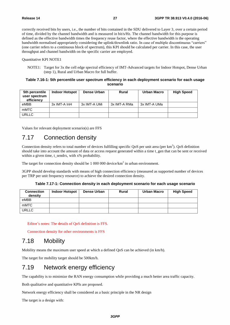
Table 7.16-1: 5th percentile user spectrum efficiency in each deployment scenario for each usage scenario
5th percentile user spectrum
efficiency
Indoor Hotspot Dense Urban Rural Urban Macro High Speed
eMBB 3x IMT-A InH 3x IMT-A UMi 3x IMT-A RMa 3x IMT-A UMa
mMTC
URLLC
Values for relevant deployment scenario(s) are FFS
7.17 Connection density
Connection density refers to total number of devices fulfilling specific QoS per unit area (per km2). QoS definition
should take into account the amount of data or access request generated within a time t_gen that can be sent or received
within a given time, t_sendrx, with x% probability.
The target for connection density should be 1 000 000 device/km2 in urban environment.
3GPP should develop standards with means of high connection efficiency (measured as supported number of devices
per TRP per unit frequency resource) to achieve the desired connection density.
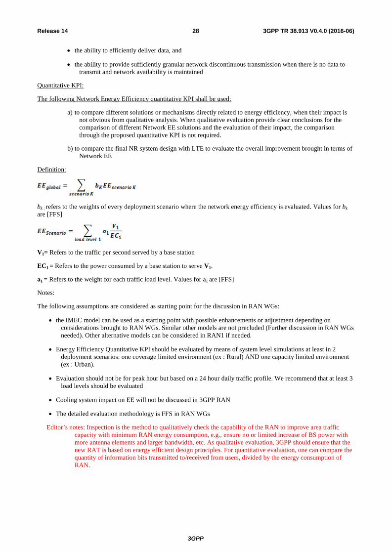
Table 7.17-1: Connection density in each deployment scenario for each usage scenario
Connection density
Indoor Hotspot Dense Urban Rural Urban Macro High Speed
eMBB
mMTC
URLLC
Editor’s notes: The details of QoS definition is FFS.
Connection density for other environments is FFS
7.18 Mobility
Mobility means the maximum user speed at which a defined QoS can be achieved (in km/h).
The target for mobility target should be 500km/h.
7.19 Network energy efficiency
The capability is to minimize the RAN energy consumption while providing a much better area traffic capacity.
Both qualitative and quantitative KPIs are proposed.
Network energy efficiency shall be considered as a basic principle in the NR design
The target is a design with:
3GPP
3GPP TR 38.913 V0.4.0 (2016-06) 28 Release 14
the ability to efficiently deliver data, and
the ability to provide sufficiently granular network discontinuous transmission when there is no data to
transmit and network availability is maintained
Quantitative KPI:
The following Network Energy Efficiency quantitative KPI shall be used:
a) to compare different solutions or mechanisms directly related to energy efficiency, when their impact is
not obvious from qualitative analysis. When qualitative evaluation provide clear conclusions for the
comparison of different Network EE solutions and the evaluation of their impact, the comparison
through the proposed quantitative KPI is not required.
b) to compare the final NR system design with LTE to evaluate the overall improvement brought in terms of
Network EE
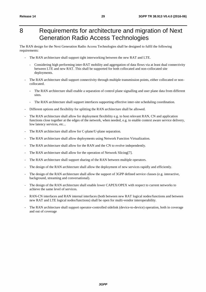
Definition:
bk : refers to the weights of every deployment scenario where the network energy efficiency is evaluated. Values for bk
are [FFS]
V1= Refers to the traffic per second served by a base station
EC1 = Refers to the power consumed by a base station to serve V1.
a1 = Refers to the weight for each traffic load level. Values for a1 are [FFS]
Notes:
The following assumptions are considered as starting point for the discussion in RAN WGs:
the IMEC model can be used as a starting point with possible enhancements or adjustment depending on
considerations brought to RAN WGs. Similar other models are not precluded (Further discussion in RAN WGs
needed). Other alternative models can be considered in RAN1 if needed.
Energy Efficiency Quantitative KPI should be evaluated by means of system level simulations at least in 2
deployment scenarios: one coverage limited environment (ex : Rural) AND one capacity limited environment
(ex : Urban).
Evaluation should not be for peak hour but based on a 24 hour daily traffic profile. We recommend that at least 3
load levels should be evaluated
Cooling system impact on EE will not be discussed in 3GPP RAN
The detailed evaluation methodology is FFS in RAN WGs
Editor’s notes: Inspection is the method to qualitatively check the capability of the RAN to improve area traffic
capacity with minimum RAN energy consumption, e.g., ensure no or limited increase of BS power with
more antenna elements and larger bandwidth, etc. As qualitative evaluation, 3GPP should ensure that the
new RAT is based on energy efficient design principles. For quantitative evaluation, one can compare the
quantity of information bits transmitted to/received from users, divided by the energy consumption of
RAN.
3GPP
3GPP TR 38.913 V0.4.0 (2016-06) 29 Release 14
8 Requirements for architecture and migration of Next Generation Radio Access Technologies
The RAN design for the Next Generation Radio Access Technologies shall be designed to fulfil the following
requirements:
- The RAN architecture shall support tight interworking between the new RAT and LTE.
- Considering high performing inter-RAT mobility and aggregation of data flows via at least dual connectivity
between LTE and new RAT. This shall be supported for both collocated and non-collocated site
deployments.
- The RAN architecture shall support connectivity through multiple transmission points, either collocated or non-
collocated.
- The RAN architecture shall enable a separation of control plane signalling and user plane data from different
sites.
- The RAN architecture shall support interfaces supporting effective inter-site scheduling coordination.
- Different options and flexibility for splitting the RAN architecture shall be allowed.
- The RAN architecture shall allow for deployment flexibility e.g. to host relevant RAN, CN and application
functions close together at the edges of the network, when needed, e.g. to enable context aware service delivery,
low latency services, etc...
- The RAN architecture shall allow for C-plane/U-plane separation.
- The RAN architecture shall allow deployments using Network Function Virtualization.
- The RAN architecture shall allow for the RAN and the CN to evolve independently.
- The RAN architecture shall allow for the operation of Network Slicing[7].
- The RAN architecture shall support sharing of the RAN between multiple operators.
- The design of the RAN architecture shall allow the deployment of new services rapidly and efficiently.
- The design of the RAN architecture shall allow the support of 3GPP defined service classes (e.g. interactive,
background, streaming and conversational).
- The design of the RAN architecture shall enable lower CAPEX/OPEX with respect to current networks to
achieve the same level of services.
- RAN-CN interfaces and RAN internal interfaces (both between new RAT logical nodes/functions and between
new RAT and LTE logical nodes/functions) shall be open for multi-vendor interoperability.
- The RAN architecture shall support operator-controlled sidelink (device-to-device) operation, both in coverage
and out of coverage
3GPP
3GPP TR 38.913 V0.4.0 (2016-06) 30 Release 14
9 Supplementary-Service related requirements
9.1 Multimedia Broadcast/Multicast Service
9.2 Location/Positioning Service
The NR should enable, and improve if suitable, state-of-art positioning techniques, such as RAN-embedded (Cell-Id, OTDOA, etc.) and RAN-external (GNSS, Bluetooth, WiFi, terrestrial beacons, etc…).
9.3 Critical Communications services
9.3.1 Public safety communications
The RAN design for the Next Generation Radio Access Technologies shall provide D2D (e.g., ProSe) support for
Public Safety (such as is found in [8]).
The RAN design for the Next Generation Radio Access Technologies shall provide Mission Critical Communications
(e.g., MCPTT) support (such as is found in [9]).
The RAN design for the Next Generation Radio Access Technologies shall provide efficient group communications
(e.g., GCSE_LTE, SC-PTM) support (such as is found in [10] and [11] respectively).
9.3.2 Emergency communications
The RAN design for the Next Generation Radio Access Technologies shall provide mechanisms to enable emergency
calls including positioning/location for emergency calls (such as is found in [12] section 10 for emergency calls and
[13] for position/location) when appropriate.
The RAN design for the Next Generation Radio Access Technologies shall provide mechanisms to enable Multimedia
Priority Services (such as is found in [14]).
9.3.3 Public warning/emergency alert systems
The RAN design for the Next Generation Radio Access Technologies shall provide mechanisms to enable public
warning services that provides warning/notifications to users meeting regional regulatory requirements (such as is found
in [15]).
3GPP
3GPP TR 38.913 V0.4.0 (2016-06) 31 Release 14
10 Operational requirements
10.0 General
The RAN design for the Next Generation Radio Access Technologies shall be designed to fulfill the following
requirements:
- RF requirements for multistandard base stations shall be supported also for the new RAT
- The RAN nodes shall be designed to allow upgrade by software as much as possible
10.1 Spectrum
10.1.1 Deployment possible in at least one identified IMT-band
10.1.2 Channel bandwidth scalability
Bandwidth scalability means the ability to operate with different bandwidth allocations.
Qualitative KPI
Editor’s notes: Whether to add number of bandwidths to be supported is FFS.
10.1.3 Spectrum flexibility
10.1.4 Duplexing flexibility
Duplexing flexibility means the ability of the access technology to adapt its allocation of resources flexibly for uplink
and downlink for both paired and unpaired frequency bands.
10.1.5 Support of shared spectrum
Next Generation Radio Access Technologies should support efficient mechanisms to share spectrum with other
IMT/Non-IMT systems.
10.1.6 Spectrum range
Next Generation Radio Access Technologies should support potential use of frequency range up to 100 GHz.
10.2 Support for wide range of services
Support for wide range of services means the system shall be inherently flexible enough to meet the connectivity
requirements of a range of existing and future (as yet unknown) services to be deployable on a single continuous block
of spectrum in an efficient manner.
10.3 Co-existence and interworking with legacy RATs
10.4 Control of EMF exposure levels requirements
10.5 Interworking with non-3GPP systems
10.5.1 General
3GPP system shall support procedures for interworking with non 3GPP RATs.
10.5.2 Interworking with WLAN
The next generation access network shall support interworking with WLAN. The number of solutions selected should
be minimized.
3GPP
3GPP TR 38.913 V0.4.0 (2016-06) 32 Release 14
10.5.3 Interworking with other non-3GPP systems
[FFS]
10.6 Radio Resource Management requirements
10.7 Easy operation and Self Organization requirements
The RAN design for the Next Generation Radio Access Technologies shall be designed to fulfill the following
requirements:
- RAN shall support the deployment of RAN SON functions in a hybrid manner (distributed and centralized).
- Collaboration and coordination among RAN SON functions need to be addressed.
- User / application level QoS and QoE monitoring capability by Ues and network elements shall be supported.
10.8 Complexity-related requirements
10.9 Cost-related requirements
3GPP shall support ultra-low cost network infrastructures, ultra-low cost devices, and ultra-low cost operation
and maintenance to enable economically viable deployments for the Provision of minimal services (Data and
Voice) for very low-ARPU areas.
10.10 Energy-related requirements
10.11 Security and Privacy related requirement relevant for Radio Access
The RAN design for the Next Generation Radio Access Technologies shall ensure support for integrity and
confidentiality protection of radio signalling messages, including messages between RAN and Core network nodes.
The RAN design for the Next Generation Radio Access Technologies shall ensure the ability to support integrity and
confidentiality protection of user plane messages, including messages between RAN and Core network nodes, with the
use of such security to be configurable during security set-up.
The RAN design for the Next Generation Radio Access Technologies shall ensure support for the allocation and use of
identities to provide user privacy, e.g. reduce the need for sending any permanent identities in the clear.
The RAN design for the Next Generation Radio Access Technologies shall ensure the efficient establishment of RAN
security mechanisms.
The RAN design for the Next Generation Radio Access Technologies shall ensure resilience against jamming.
NOTE: Security and Privacy-related system requirements are reflected in [17]. This TR includes security areas on
"RAN security" and "Privacy security", which is a possible source of security and privacy related
requirements for the Radio Access.
10.12 Performance monitoring and management
10.13 Lawful Interception
The RAN design for the Next Generation Radio Access Technologies shall provide mechanisms to enable lawful
intercept for appropriate services (as per [16]).
10.14 Backhaul and signaling optimization requirements
The RAN system shall have the capability to minimize the backhaul and signaling load in line with the requirements in
section 5.48 of [2]).
3GPP
3GPP TR 38.913 V0.4.0 (2016-06) 33 Release 14
10.15 Relay requirements
The design of the 5G RAN and Radio Interface Technology shall aim at supporting wireless relay functions.
10.16 High availability
The RAN availability is characterized by its availability rate X, defined as follows: a base station is available for the
targeted communication X% of the time. Unavailable communication for shorter period than [Y] ms shall not be
counted.
The NR specification’s ability to provide URLLC services shall not be compromised by the functions defined to
improve the network or UE energy efficiency, or by system reconfigurations and software upgrades.
10.17 Other operational requirements

3GPP
3GPP TR 38.913 V0.4.0 (2016-06) 34 Release 14
11 Testing and Conformance Requirements
- Conformance requirements shall be defined for NR on all deployment bands
- Features/components of NR shall be designed in such a way that it is feasible to define test specifications for
these features/components for both UE and BS on all deployment bands
3GPP
3GPP TR 38.913 V0.4.0 (2016-06) 35 Release 14
Annex A: Change history
Change history Date TSG # TSG Doc. CR Rev Subject/Comment Old New
2015-11 RP-70 RP-151761 Draft skeleton for the TR - 0. 0.0
2015-11 RP-70 RP-152183 Revised the reference SI to the updated SI, removed the change mark
0.0.0 0.0.1
2016-01 RP-AH Rpa160013 Revised the Skeleton TR based on the Report of email discussion Rpa-160012
0.0.1 0.0.2
2016-01 RP-AH Rpa160070 Merge all requirements into one section, renamed the section as key performance indicator
0.0.2 0.0.3
2016-01 RP-AH Rpa160071 Move support for wide range of service from KPI section into operational section Move spectral related sections from KPI section into operational section Remove E2E latency requirements; agreed skeleton TR
0.0.3 0.1.0
2016-01 RP-AH Rpa160080 Implementation of approved pCRs Rpa160077, Rpa160078 and Rpa160079 into the skeleton TR Rpa160071 as input for RAN email discussion [5G-AH-01]
0.1.0 0.1.1
2016-02 RP-AH Rpa160081 Minor editorial corrections on top of Rpa160080 (result of RAN email discussion [5G-AH-01])
0.1.1 0.1.2
2016-02 RP-AH Rpa160082 RAN agreed TR after ad hoc and email discussion [5G-AH-01]
0.1.2 0.2.0
2016-03 RP-71 RP-160688 Updated TR including all agreements of RAN #71, e.g. pCRs RP-160554, RP-160555, RP-160562, RP-160566, RP-160589, RP-160611, RP-160629, RP-160637, RP-160640, RP-160642, RP-160643, RP-160646, RP-160672
0.2.0 0.2.1
2016-03 RP-71 RP-160689 TR after RAN #71 that was agreed by email discussion [RAN#71-01]: changes from v0.2.1 plus editorial clean-up from MCC
0.2.1 0.3.0
2016-06 RP-72 RP-160810 Updated TR including all agreements of RAN #72, e.g. pCRs RP-160962, RP-160963, RP-160964, RP-160965, RP-161206, RP-160967, RP-161205, RP-161207, RP-160969, RP-160970, RP-161213, RP-161317, RP-161254, RP-161100, RP-161277, RP-161210, RP-161208, RP-161050
0.3.0 0.3.1
2016-06 RP-72 RP-161134 RAN agreed TR after email discussion [RAN #72-01] 0.3.1 0.4.0
Recommended


![TURKEY——— [TR] STAR TV HD [TR] STAR TV HD [L] [TR] STAR TV ... · [tr] hilal tv [tr] sinevizyonlaŔ da ne var [tr] sinevizyon 1 hd [tr] sinevizyon 2 hd [tr] sinevizyon 3 hd](https://img.pdfslide.us/doc/110x75/5e1690ad410818078675a933/turkeyaaa-tr-star-tv-hd-tr-star-tv-hd-l-tr-star-tv-tr-hilal.jpg)