3GPP – Long Term Evolution – A Technical Study
1
Mr. Vishal PawarMITSOT

Main Topics • Introduction to LTE• LTE Network Architecture• LTE Physical Layer • SC-FDMA• Channel Dependent Scheduling • Cognitive Radio for LTE RRM• Multiple antenna schemes in LTE • LTE-Advanced• Conclusion
2

Introduction to LTE
• 3GPP Long Term Evolution - the next generation of wireless cellular technology beyond 3G
• Initiative taken by the 3rd Generation Partnership Project in 2004
• Introduced in Release 8 of 3GPP
• Mobile systems likely to be deployed by 2010
3

Requirements to be met by LTEFast, Efficient, Cheap, Simple
• Peak Data Rates• Spectrum efficiency• Reduced Latency• Mobility• Spectrum flexibility• Coverage• Low complexity and cost• Interoperability• Simple packet-oriented E-UTRAN architecture
4

LTE Network Architecture
5
• Simple Architecture• Flat IP-Based Architecture• Reduction in latency and cost• Split between EPC and E-UTRAN• Compatibility with 3GPP and
non-3GPP technologies• eNB-radio interface-related
functions• MME-manages mobility, UE
identity and security parameters
• S-GW-node that terminates the interface towards E-UTRAN
eNB
MME / S-GW MME / S-GW
eNB
eNB
S1
S1
X2 E-UTRAN

LTE Network Architecture
6

June 26 2009 7
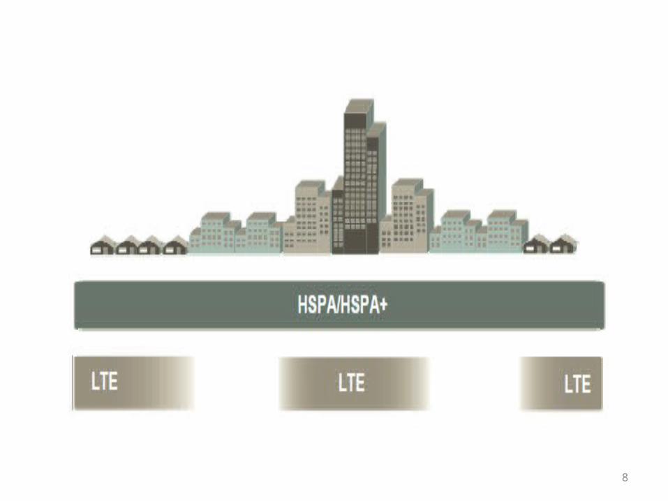
8

LTE Frame Structure
• LTE Frame Structure Type I (FDD)
9

LTE Frame Structure Type II (TDD)
June 26 2009 MITSOT_MCNE_LTE 10

Single-Carrier Frequency Division Multiple Access (SC-FDMA)
• Motivation for SC-FDMA
• SC-FDMA utilizes single carrier modulation at the transmitter and frequency domain equalization at the receiver.
• It has the best of both worlds - the low PAPR of single carrier systems and the multipath resistance and channel dependent subcarrier allocation features of OFDM.
• Same complexity and performance as OFDMA
11

The “SC”-”FDMA” System
DFT-Spread OFDMA – Mapping of spread symbols , not original symbols to subcarriers!!!
12

Subcarrier Mapping Schemes
• Localized (LFDMA)• Distributed (DFDMA)• Interleaved (IFDMA)
13

Frequency and Time Domain Representation
14
Frequency Time

Time domain signals of LFDMA, DFDMA and IFDMA[20]
15

PAPR characteristics of an SC-FDMA signal [20]
Comparison of the CCDF of PAPR for LFDMA, DFDMA, IFDMA and OFDMA
16

Effect of roll-off factor, alpha on the PAPR[20]
17

Why does SC-FDMA have a low PAPR?
• OFDMA • Parallel Transmission • Multi carrier structure• Increase in M => high PAPR• SC-FDMA • Serial Transmission• Each symbol represented by a wide signal – DFT spreads symbols over all subcarriers• PAPR not affected by increase in M
Both occupy the same bandwidth with same symbol durations
18

SC-FDMA in comparison with OFDMA and DS-CDMA/FDE
19
DS-CDMA/FDE

Channel Dependent Scheduling
• Channel is highly frequency selective
• Resources in deep fade for one user could be excellent for another user
• Frequency selectivity of the channel can be exploited by using CDS to maximize throughput
• LFDMA – frequency selective diversity
• IFDMA – Multi user diversity (inherently frequency diversity is obtained)
20

Cognitive RRM in LTE
• Link adaptation possible as network segments in LTE adapt to the environmental changes
• System can learn from solutions that were provided in the past
• Faster response, improved performance, intelligent system
• Decisions reg. apt BW,DSA,APA and AM
21

Cognitive Features to enhance RRM in LTE
22
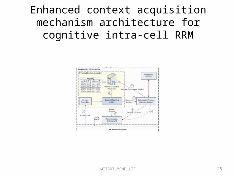
Enhanced context acquisition mechanism architecture for cognitive intra-cell RRM
MITSOT_MCNE_LTE 23

Multiple Antenna Schemes in LTE
• In DL : Tx diversity, Rx diversity, Spatial multiplexing (2x2,4x2 configurations – SU-MIMO and MU-MIMO) supported
• In UL : Only 1 Transmitter (antenna selection Tx diversity ), MU-MIMO possible, Rx diversity with 2 or 4 antennas at eNB supported
24

LTE Advanced• LTE doesn’t fulfill the requirements of IMT-Advanced
• 3GPP has also started work on LTE-Advanced, an evolution of LTE, as a proposal to ITU-R for the development of IMT Advanced.
• LTE Advanced is envisioned to be the “first true 4G technology”.
25

Requirements of LTE Advanced
• Peak data rates – 1Gbps in DL and 500 Mbps in UL• Cell edge user data rates twice as high and average user throughput
thrice as high as in LTE• Peak spectrum efficiency DL: 30 bps/Hz, UL: 15 bps/Hz• Operate in flexible spectrum allocations up to 100 MHz and support
spectrum aggregation (as BW in DL >>20 MHz)• An LTE-Advanced capable network must appear as a LTE network
for the LTE UEs
26

Technological proposals for LTE Advanced
• Larger BW can be used for high date rates and more coverage at cell edges
• Advanced repeater structures• Relaying for adaptive coding
based on link quality
MITSOT_MCNE_LTE 27
Carrier aggregation and Spectrum aggregation

Thank You !
28
Recommended