February 2011, 18(1): 105–112 www.sciencedirect.com/science/journal/10058885 http://www.jcupt.com
The Journal of China Universities of Posts and Telecommunications
3D augmented reality teleoperated robot system based on dual vision GAO Xin ( ), HU Huan, JIA Qing-xuan, SUN Han-xu, SONG Jing-zhou
School of Automation, Beijing University of Posts and Telecommunications, Beijing 100876, China
Abstract
A 3D augmented reality navigation system using stereoscopic images is developed for teleoperated robot systems. The accurate matching between the simulated model and the video image of the actual robot can be realized, which helps the operator to accomplish the remote control task correctly and reliably. The system introduces the disparity map translation transformation method to take parallax images for stereoscopic displays, providing the operator an immersive 3D experience. Meanwhile, a fast and accurate registration method of dynamic stereo video is proposed, and effective integration of a virtual robot and the real stereo scene can be achieved. Preliminary experiments show that operation error of the system is maintained at less than 2.2 mm and the average error is 0.854 7, 0.909 3 and 0.697 2 mm at x, y, z direction respectively. Lots of experiments such as pressing the button, pulling the drawer and so on are also conducted to evaluate the performance of the system. The feasibility studies show that the depth information of structure can be rapidly and recognized in remote environment site. The augmented reality of the image overlay system could increase the operating accuracy and reduce the procedure time as a result of intuitive 3D viewing.
Keywords teleoperated robotic system, augmented reality, immersive interface, stereo display, binocular registration
1 Introduction
The teleoperation of the mobile robot can decrease the technological challenges in making a completely safe autonomous platform operating in uncertain and changing environments [1–2]. However, the time-varying delays in the communication channel may degrade the performance of the teleoperation systems [3–4]. In order to overcome the influence of time delays, the predictive graphical simulation technology is applied into the teleoperation systems [5–6], but, for the complex and uncertain environments, it is difficult or impossible to build the modeling of the remote operating environment in advance.
To overcome these problems, it is an effective way to incorporated augmented reality (AR) technology into the remote operating system. The information conveyed by the virtual objects in AR is intended to help the human user have a better understanding about the real world, and thus perform associated real-world tasks better. However, the commonly
Received date: 19-08-2010 Corresponding author: GAO Xin, E-mail: [email protected] DOI: 10.1016/S1005-8885(10)60035-0
AR display systems using 2D image suffer from many limitations in robot teleoperation, for instance, misjudgment of self-motion and spatial localization, and limited comprehension of remote ambient layout, object size and shape. The above problems lead to unwanted collisions during navigation, as well as long training periods for an operator. The use of 3D stereoscopic visualization can provide a user with a higher sense of presence in remote environments because higher depth perception leads to higher comprehension of distance, as well as aspects related to it,such as, ambient layout, obstacles perception and manoeuvre accuracy [7–8].
The main purpose of this paper is to construct the AR teleoperation system based on dual vision. It can offer the operator the accurate matching between the simulated model and the dual video images, and assist the operator to accomplish the remote control task correctly and reliably. The system introduces the disparity map translation transformation method to take parallax images for stereoscopic displays, providing the operator an immersive 3D experience. Fast registration method of dynamic stereo video is proposed, achieving effective integration of a virtual robot and the real stereo scene. This paper is organized as follows. In Sect. 2,
106 The Journal of China Universities of Posts and Telecommunications 2011
the architecture of the AR teleoperated system is introduced. Sect. 3 studies a related work in the area of stereo display. Sect. 4 presents the method of fast tracking with dual cameras for augmented reality. The system implementation is provided in Sect. 5. Finally, we conclude with Sect. 6.
2 System architecture
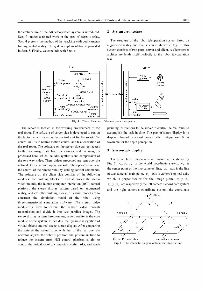
The structure of the robot teleoperation system based on augmented reality and dual vision is shown in Fig. 1. This system consists of two parts: server and client. A client/server architecture lends itself perfectly to the robot teleoperation task.
Fig. 1 The architecture of the teleoperation system
The server is located in the working environment of the real robot. The software of server side is developed to run on the laptop which serves as the control unit for the robot. The control unit is to realize motion control and task execution of the real robot. The software on the server side can get access to the raw image data from the camera, and the image is processed here, which includes synthesis and compression of the two-way video. Then, videos processed are sent over the network to the remote operation side. The operators achieve the control of the remote robot by sending control commands. The software on the client side consists of the following modules: the building blocks of virtual model, the stereo video module, the human-computer interaction (HCI) control platform, the stereo display system based on augmented reality, and etc. The building blocks of virtual model are to construct the simulation model of the robot using three-dimensional simulation software. The stereo video module is used to extract the remote video through transmission and divide it into two parallax images. The stereo display system based-on augmented reality is the core module of the system. It includes: the dynamic integration of virtual objects and real scene, stereo display. After comparing the state of the virtual robot with that of the real one, the operator adjusts the robot’s position and posture in time to reduce the system error. HCI control platform is aim to control the virtual robot to complete specific tasks, and sends
planning instructions to the server to control the real robot to accomplish the task in time. The part of stereo display is to display three-dimensional scene after integration. It is favorable for the depth perception.
3 Stereoscopic display
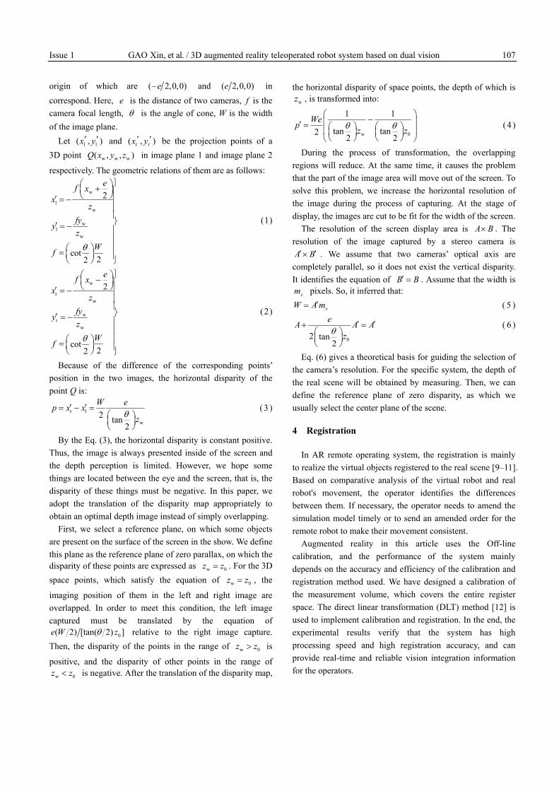
The principle of binocular stereo vision can be shown by Fig. 2. w w w, , x y z is the world coordinate system, wo is the center point of the two cameras’ line, wx axis is the line of two cameras’ main point, wz axis is camera’s optical axis, which is perpendicular for the image plane. l l l, , x y z ,
r r r, , x y z are respectively the left camera’s coordinate system
and the right camera’s coordinate system, the coordinate
Fig. 2 The schematic diagram of binocular stereo vision
Issue 1 GAO Xin, et al. / 3D augmented reality teleoperated robot system based on dual vision 107
origin of which are ( 2,0,0)e− and ( 2,0,0)e in correspond. Here, e is the distance of two cameras, f is the camera focal length, θ is the angle of cone, W is the width of the image plane.
Let l l( , )x y′ ′ and r r( , )x y′ ′ be the projection points of a 3D point w w w( , , )Q x y z in image plane 1 and image plane 2
respectively. The geometric relations of them are as follows:
w
lw
wl
w
2
cot22
ef xx
zfyyz
Wf θ
⎫⎛ ⎞+⎜ ⎟⎪⎝ ⎠′ = − ⎪⎪⎪⎬′ = − ⎪⎪⎪⎛ ⎞= ⎜ ⎟ ⎪⎝ ⎠ ⎭
(1)
w
rw
wr
w
2
cot22
ef xx
zfyyz
Wf θ
⎫⎛ ⎞−⎜ ⎟⎪⎝ ⎠′ = − ⎪⎪⎪⎬′ = − ⎪⎪⎪⎛ ⎞= ⎜ ⎟ ⎪⎝ ⎠ ⎭
(2)
Because of the difference of the corresponding points’ position in the two images, the horizontal disparity of the point Q is:
r l
w2 tan
2
W ep x xzθ
′ ′= − =⎛ ⎞⎜ ⎟⎝ ⎠
( 3 )
By the Eq. (3), the horizontal disparity is constant positive. Thus, the image is always presented inside of the screen and the depth perception is limited. However, we hope some things are located between the eye and the screen, that is, the disparity of these things must be negative. In this paper, we adopt the translation of the disparity map appropriately to obtain an optimal depth image instead of simply overlapping.
First, we select a reference plane, on which some objects are present on the surface of the screen in the show. We define this plane as the reference plane of zero parallax, on which the disparity of these points are expressed as w 0z z= . For the 3D space points, which satisfy the equation of w 0z z= , the
imaging position of them in the left and right image are overlapped. In order to meet this condition, the left image captured must be translated by the equation of
0( 2) [tan( 2) ]e W zθ relative to the right image capture. Then, the disparity of the points in the range of w 0z z> is
positive, and the disparity of other points in the range of w 0z z< is negative. After the translation of the disparity map,
the horizontal disparity of space points, the depth of which is wz , is transformed into:
w 0
1 1
tan tan22 2
Wep z zθ θ⎛ ⎞−⎜ ⎟′ = ⎛ ⎞ ⎛ ⎞⎜ ⎟⎜ ⎟ ⎜ ⎟
⎝ ⎠ ⎝ ⎠⎝ ⎠
( 4 )
During the process of transformation, the overlapping regions will reduce. At the same time, it causes the problem that the part of the image area will move out of the screen. To solve this problem, we increase the horizontal resolution of the image during the process of capturing. At the stage of display, the images are cut to be fit for the width of the screen.
The resolution of the screen display area is A B× . The resolution of the image captured by a stereo camera is A B′ ′× . We assume that two cameras’ optical axis are
completely parallel, so it does not exist the vertical disparity. It identifies the equation of B B′ = . Assume that the width is
xm pixels. So, it inferred that:
xW A m′= ( 5 )
02 tan2
eA A Azθ
′ ′+ =⎛ ⎞⎜ ⎟⎝ ⎠
( 6 )
Eq. (6) gives a theoretical basis for guiding the selection of the camera’s resolution. For the specific system, the depth of the real scene will be obtained by measuring. Then, we can define the reference plane of zero disparity, as which we usually select the center plane of the scene.
4 Registration
In AR remote operating system, the registration is mainly to realize the virtual objects registered to the real scene [9–11]. Based on comparative analysis of the virtual robot and real robot's movement, the operator identifies the differences between them. If necessary, the operator needs to amend the simulation model timely or to send an amended order for the remote robot to make their movement consistent.
Augmented reality in this article uses the Off-line calibration, and the performance of the system mainly depends on the accuracy and efficiency of the calibration and registration method used. We have designed a calibration of the measurement volume, which covers the entire register space. The direct linear transformation (DLT) method [12] is used to implement calibration and registration. In the end, the experimental results verify that the system has high processing speed and high registration accuracy, and can provide real-time and reliable vision integration information for the operators.
108 The Journal of China Universities of Posts and Telecommunications 2011
4.1 The calibration and registration method
The specific calibration and registration method includes the following steps:
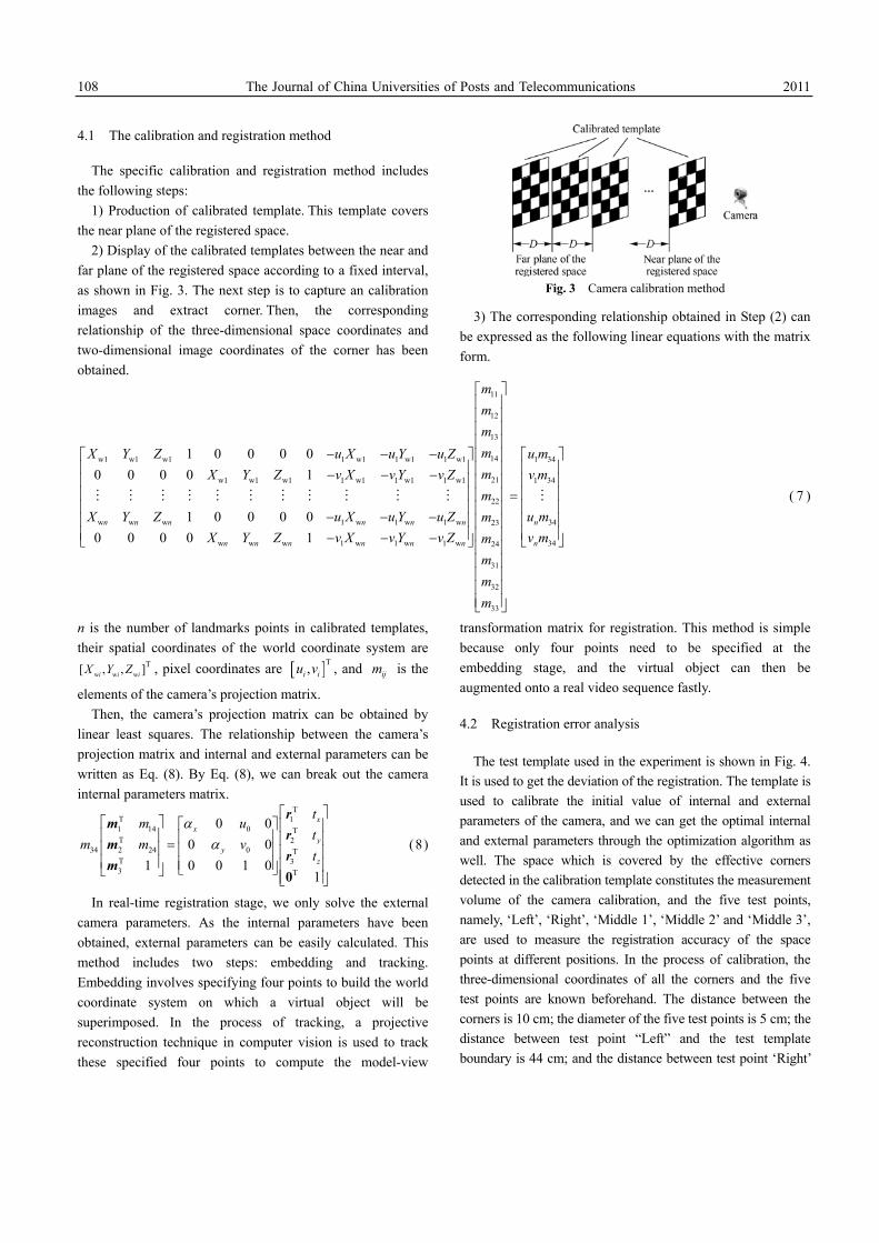
1) Production of calibrated template. This template covers the near plane of the registered space.
2) Display of the calibrated templates between the near and far plane of the registered space according to a fixed interval, as shown in Fig. 3. The next step is to capture an calibration images and extract corner. Then, the corresponding relationship of the three-dimensional space coordinates and two-dimensional image coordinates of the corner has been obtained.
Fig. 3 Camera calibration method
3) The corresponding relationship obtained in Step (2) can be expressed as the following linear equations with the matrix form.
11
12
13
14w1 w1 w1 1 w1 1 w1 1 w1
21w1 w1 w1 1 w1 1 w1 1 w1
22
w w w 1 w 1 w 1 w 23
w w w 1 w 1 w 1 w 24
31
32
33
1 0 0 0 00 0 0 0 1
1 0 0 0 00 0 0 0 1
n n n n n n
n n n n n n
mmmmX Y Z u X u Y u ZmX Y Z v X v Y v Zm
X Y Z u X u Y u Z mX Y Z v X v Y v Z m
mmm
⎡⎢⎢⎢⎢
− − −⎡ ⎤ ⎢⎢ ⎥ ⎢− − −⎢ ⎥ ⎢⎢ ⎥ ⎢⎢ ⎥ ⎢− − −⎢ ⎥ ⎢⎢ ⎥− − −⎣ ⎦
⎣
1 34
1 34
34
34
n
n
u mv m
u mv m
⎤⎥⎥⎥⎥
⎡ ⎤⎥⎢ ⎥⎥⎢ ⎥⎥⎢ ⎥⎥ =⎢ ⎥⎥⎢ ⎥⎥⎢ ⎥⎢ ⎥ ⎣ ⎦⎢ ⎥
⎢ ⎥⎢ ⎥⎢ ⎥⎢ ⎥⎦
( 7 )
n is the number of landmarks points in calibrated templates, their spatial coordinates of the world coordinate system are
w w wT[ , , ]i i iX Y Z , pixel coordinates are [ ]T,i iu v , and ijm is the
elements of the camera’s projection matrix. Then, the camera’s projection matrix can be obtained by
linear least squares. The relationship between the camera’s projection matrix and internal and external parameters can be written as Eq. (8). By Eq. (8), we can break out the camera internal parameters matrix.
TT 11 14 0 TT 2
34 2 24 0 TT 33 T
0 00 0
1 0 0 1 01
xx
yy
z
tm u
tm m v
t
αα
⎡ ⎤⎡ ⎤ ⎡ ⎤ ⎢ ⎥⎢ ⎥ ⎢ ⎥ ⎢ ⎥=⎢ ⎥ ⎢ ⎥ ⎢ ⎥⎢ ⎥ ⎢ ⎥ ⎢ ⎥⎣ ⎦⎣ ⎦ ⎢ ⎥⎣ ⎦0
rm
rm
rm
(8)
In real-time registration stage, we only solve the external camera parameters. As the internal parameters have been obtained, external parameters can be easily calculated. This method includes two steps: embedding and tracking. Embedding involves specifying four points to build the world coordinate system on which a virtual object will be superimposed. In the process of tracking, a projective reconstruction technique in computer vision is used to track these specified four points to compute the model-view
transformation matrix for registration. This method is simple because only four points need to be specified at the embedding stage, and the virtual object can then be augmented onto a real video sequence fastly.
4.2 Registration error analysis
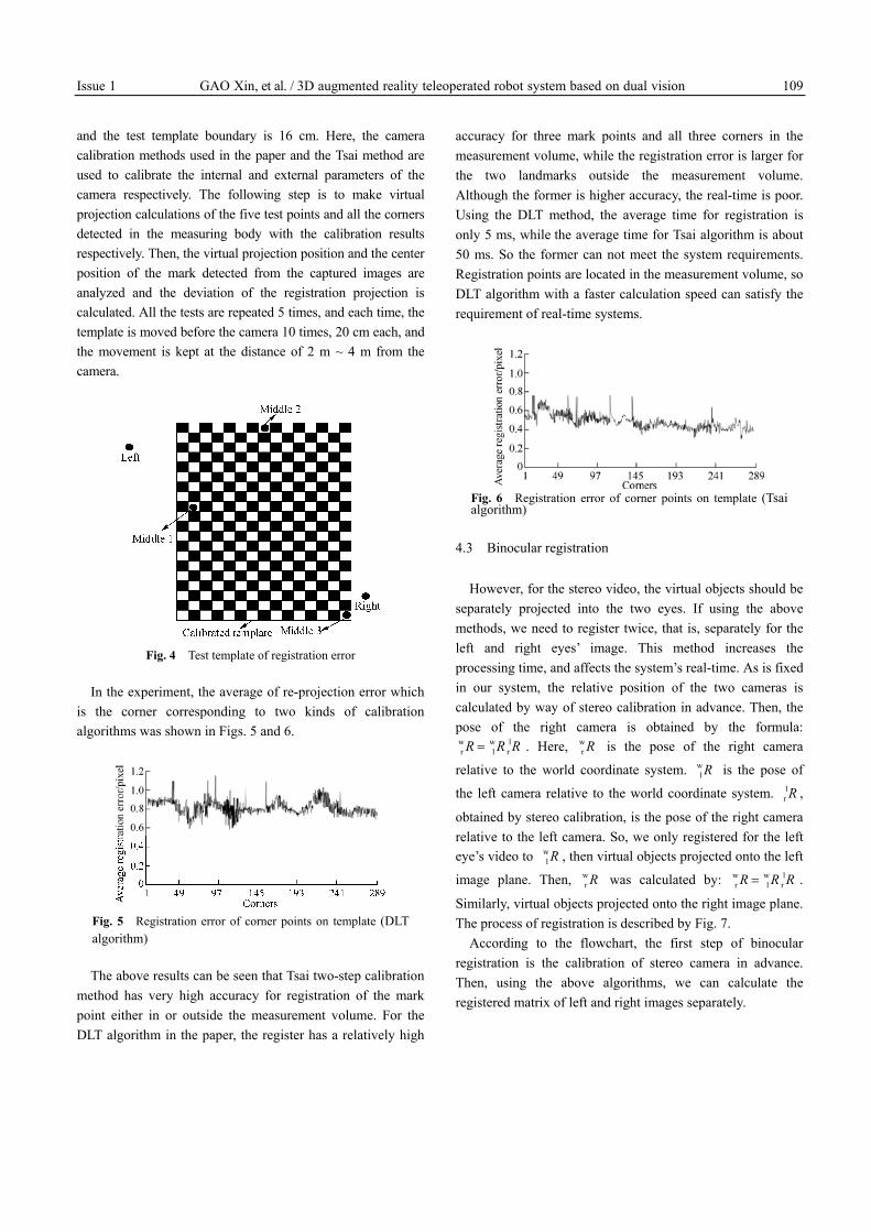
The test template used in the experiment is shown in Fig. 4. It is used to get the deviation of the registration. The template is used to calibrate the initial value of internal and external parameters of the camera, and we can get the optimal internal and external parameters through the optimization algorithm as well. The space which is covered by the effective corners detected in the calibration template constitutes the measurement volume of the camera calibration, and the five test points, namely, ‘Left’, ‘Right’, ‘Middle 1’, ‘Middle 2’ and ‘Middle 3’, are used to measure the registration accuracy of the space points at different positions. In the process of calibration, the three-dimensional coordinates of all the corners and the five test points are known beforehand. The distance between the corners is 10 cm; the diameter of the five test points is 5 cm; the distance between test point “Left” and the test template boundary is 44 cm; and the distance between test point ‘Right’
Issue 1 GAO Xin, et al. / 3D augmented reality teleoperated robot system based on dual vision 109
and the test template boundary is 16 cm. Here, the camera calibration methods used in the paper and the Tsai method are used to calibrate the internal and external parameters of the camera respectively. The following step is to make virtual projection calculations of the five test points and all the corners detected in the measuring body with the calibration results respectively. Then, the virtual projection position and the center position of the mark detected from the captured images are analyzed and the deviation of the registration projection is calculated. All the tests are repeated 5 times, and each time, the template is moved before the camera 10 times, 20 cm each, and the movement is kept at the distance of 2 m ~ 4 m from the camera.
Fig. 4 Test template of registration error
In the experiment, the average of re-projection error which is the corner corresponding to two kinds of calibration algorithms was shown in Figs. 5 and 6.
Fig. 5 Registration error of corner points on template (DLT algorithm)
The above results can be seen that Tsai two-step calibration method has very high accuracy for registration of the mark point either in or outside the measurement volume. For the DLT algorithm in the paper, the register has a relatively high
accuracy for three mark points and all three corners in the measurement volume, while the registration error is larger for the two landmarks outside the measurement volume. Although the former is higher accuracy, the real-time is poor. Using the DLT method, the average time for registration is only 5 ms, while the average time for Tsai algorithm is about 50 ms. So the former can not meet the system requirements. Registration points are located in the measurement volume, so DLT algorithm with a faster calculation speed can satisfy the requirement of real-time systems.
Fig. 6 Registration error of corner points on template (Tsai algorithm)
4.3 Binocular registration
However, for the stereo video, the virtual objects should be separately projected into the two eyes. If using the above methods, we need to register twice, that is, separately for the left and right eyes’ image. This method increases the processing time, and affects the system’s real-time. As is fixed in our system, the relative position of the two cameras is calculated by way of stereo calibration in advance. Then, the pose of the right camera is obtained by the formula: w w lr l rR R R= . Here, w
r R is the pose of the right camera
relative to the world coordinate system. wl R is the pose of
the left camera relative to the world coordinate system. lr R ,
obtained by stereo calibration, is the pose of the right camera relative to the left camera. So, we only registered for the left eye’s video to w
l R , then virtual objects projected onto the left
image plane. Then, wr R was calculated by: w w l
r l rR R R= .
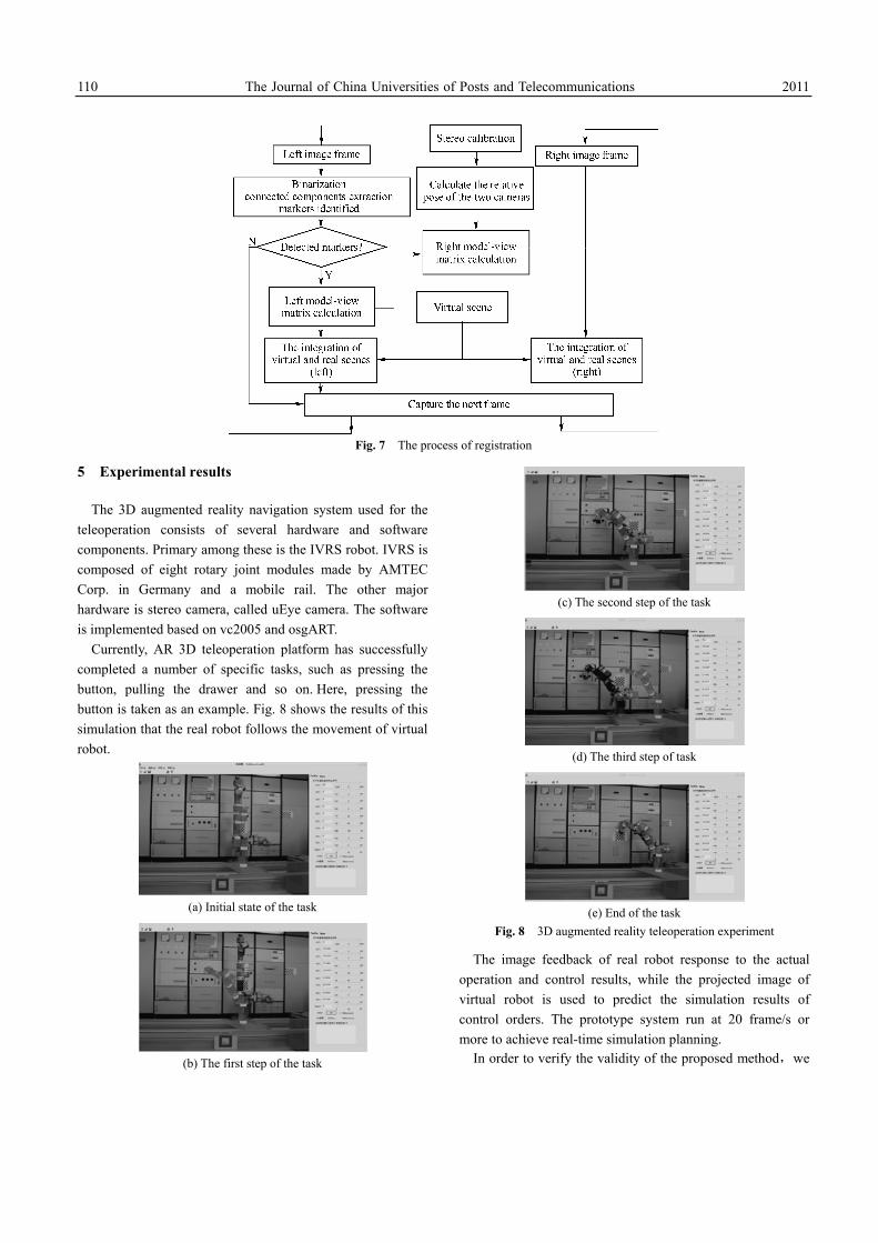
Similarly, virtual objects projected onto the right image plane. The process of registration is described by Fig. 7.
According to the flowchart, the first step of binocular registration is the calibration of stereo camera in advance. Then, using the above algorithms, we can calculate the registered matrix of left and right images separately.
110 The Journal of China Universities of Posts and Telecommunications 2011
Fig. 7 The process of registration
5 Experimental results
The 3D augmented reality navigation system used for the teleoperation consists of several hardware and software components. Primary among these is the IVRS robot. IVRS is composed of eight rotary joint modules made by AMTEC Corp. in Germany and a mobile rail. The other major hardware is stereo camera, called uEye camera. The software is implemented based on vc2005 and osgART.
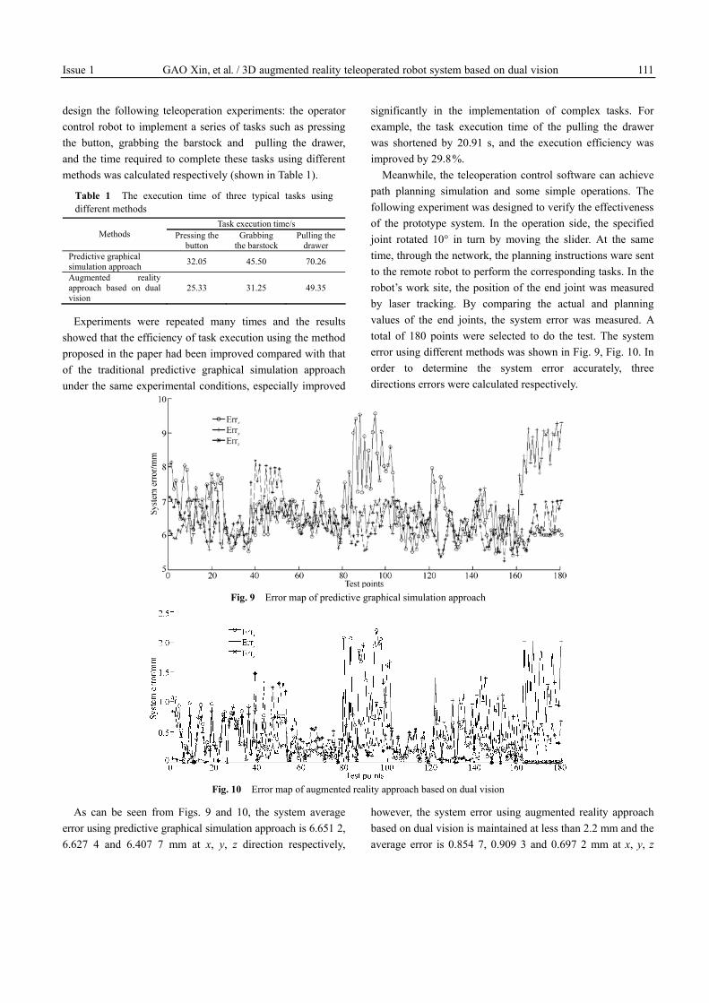
Currently, AR 3D teleoperation platform has successfully completed a number of specific tasks, such as pressing the button, pulling the drawer and so on. Here, pressing the button is taken as an example. Fig. 8 shows the results of this simulation that the real robot follows the movement of virtual robot.
(a) Initial state of the task
(b) The first step of the task
(c) The second step of the task
(d) The third step of task
(e) End of the task
Fig. 8 3D augmented reality teleoperation experiment
The image feedback of real robot response to the actual operation and control results, while the projected image of virtual robot is used to predict the simulation results of control orders. The prototype system run at 20 frame/s or more to achieve real-time simulation planning.
In order to verify the validity of the proposed method,we
Issue 1 GAO Xin, et al. / 3D augmented reality teleoperated robot system based on dual vision 111
design the following teleoperation experiments: the operator control robot to implement a series of tasks such as pressing the button, grabbing the barstock and pulling the drawer, and the time required to complete these tasks using different methods was calculated respectively (shown in Table 1).
Table 1 The execution time of three typical tasks using different methods
Task execution time/s Methods Pressing the
button Grabbing
the barstock Pulling the
drawer Predictive graphical simulation approach 32.05 45.50 70.26
Augmented reality approach based on dual vision
25.33 31.25 49.35
Experiments were repeated many times and the results showed that the efficiency of task execution using the method proposed in the paper had been improved compared with that of the traditional predictive graphical simulation approach under the same experimental conditions, especially improved
significantly in the implementation of complex tasks. For example, the task execution time of the pulling the drawer was shortened by 20.91 s, and the execution efficiency was improved by 29.8 %.
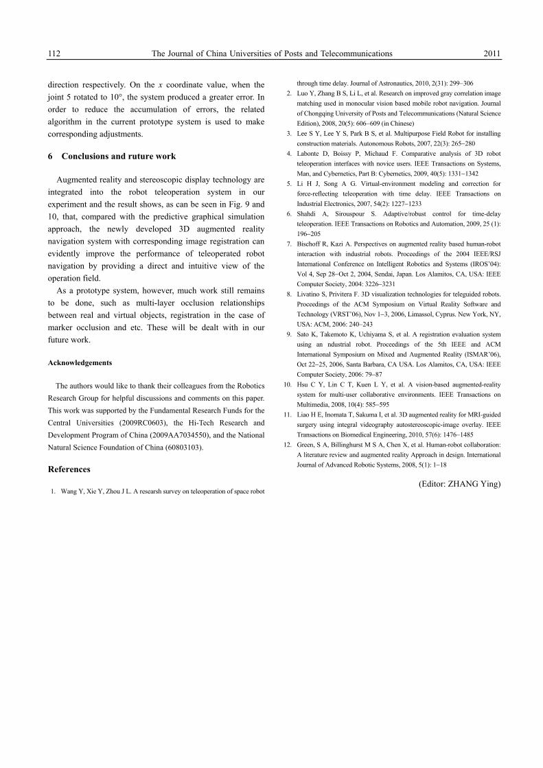
Meanwhile, the teleoperation control software can achieve path planning simulation and some simple operations. The following experiment was designed to verify the effectiveness of the prototype system. In the operation side, the specified joint rotated 10° in turn by moving the slider. At the same time, through the network, the planning instructions ware sent to the remote robot to perform the corresponding tasks. In the robot’s work site, the position of the end joint was measured by laser tracking. By comparing the actual and planning values of the end joints, the system error was measured. A total of 180 points were selected to do the test. The system error using different methods was shown in Fig. 9, Fig. 10. In order to determine the system error accurately, three directions errors were calculated respectively.
Fig. 9 Error map of predictive graphical simulation approach
Fig. 10 Error map of augmented reality approach based on dual vision
As can be seen from Figs. 9 and 10, the system average error using predictive graphical simulation approach is 6.651 2, 6.627 4 and 6.407 7 mm at x, y, z direction respectively,
however, the system error using augmented reality approach based on dual vision is maintained at less than 2.2 mm and the average error is 0.854 7, 0.909 3 and 0.697 2 mm at x, y, z
112 The Journal of China Universities of Posts and Telecommunications 2011
direction respectively. On the x coordinate value, when the joint 5 rotated to 10°, the system produced a greater error. In order to reduce the accumulation of errors, the related algorithm in the current prototype system is used to make corresponding adjustments.
6 Conclusions and ruture work
Augmented reality and stereoscopic display technology are integrated into the robot teleoperation system in our experiment and the result shows, as can be seen in Fig. 9 and 10, that, compared with the predictive graphical simulation approach, the newly developed 3D augmented reality navigation system with corresponding image registration can evidently improve the performance of teleoperated robot navigation by providing a direct and intuitive view of the operation field.
As a prototype system, however, much work still remains to be done, such as multi-layer occlusion relationships between real and virtual objects, registration in the case of marker occlusion and etc. These will be dealt with in our future work.
Acknowledgements
The authors would like to thank their colleagues from the Robotics Research Group for helpful discussions and comments on this paper. This work was supported by the Fundamental Research Funds for the Central Universities (2009RC0603), the Hi-Tech Research and Development Program of China (2009AA7034550), and the National Natural Science Foundation of China (60803103).
References
1. Wang Y, Xie Y, Zhou J L. A researsh survey on teleoperation of space robot
through time delay. Journal of Astronautics, 2010, 2(31): 299−306 2. Luo Y, Zhang B S, Li L, et al. Research on improved gray correlation image
matching used in monocular vision based mobile robot navigation. Journal of Chongqing University of Posts and Telecommunications (Natural Science Edition), 2008, 20(5): 606−609 (in Chinese)
3. Lee S Y, Lee Y S, Park B S, et al. Multipurpose Field Robot for installing construction materials. Autonomous Robots, 2007, 22(3): 265−280
4. Labonte D, Boissy P, Michaud F. Comparative analysis of 3D robot teleoperation interfaces with novice users. IEEE Transactions on Systems, Man, and Cybernetics, Part B: Cybernetics, 2009, 40(5): 1331−1342
5. Li H J, Song A G. Virtual-environment modeling and correction for force-reflecting teleoperation with time delay. IEEE Transactions on Industrial Electronics, 2007, 54(2): 1227−1233
6. Shahdi A, Sirouspour S. Adaptive/robust control for time-delay teleoperation. IEEE Transactions on Robotics and Automation, 2009, 25 (1): 196−205
7. Bischoff R, Kazi A. Perspectives on augmented reality based human-robot interaction with industrial robots. Proceedings of the 2004 IEEE/RSJ International Conference on Intelligent Robotics and Systems (IROS’04): Vol 4, Sep 28−Oct 2, 2004, Sendai, Japan. Los Alamitos, CA, USA: IEEE Computer Society, 2004: 3226−3231
8. Livatino S, Privitera F. 3D visualization technologies for teleguided robots. Proceedings of the ACM Symposium on Virtual Reality Software and Technology (VRST’06), Nov 1−3, 2006, Limassol, Cyprus. New York, NY, USA: ACM, 2006: 240−243
9. Sato K, Takemoto K, Uchiyama S, et al. A registration evaluation system using an ndustrial robot. Proceedings of the 5th IEEE and ACM International Symposium on Mixed and Augmented Reality (ISMAR’06), Oct 22−25, 2006, Santa Barbara, CA USA. Los Alamitos, CA, USA: IEEE Computer Society, 2006: 79−87
10. Hsu C Y, Lin C T, Kuen L Y, et al. A vision-based augmented-reality system for multi-user collaborative environments. IEEE Transactions on Multimedia, 2008, 10(4): 585−595
11. Liao H E, Inomata T, Sakuma I, et al. 3D augmented reality for MRI-guided surgery using integral videography autostereoscopic-image overlay. IEEE Transactions on Biomedical Engineering, 2010, 57(6): 1476−1485
12. Green, S A, Billinghurst M S A, Chen X, et al. Human-robot collaboration: A literature review and augmented reality Approach in design. International Journal of Advanced Robotic Systems, 2008, 5(1): 1−18
(Editor: ZHANG Ying)
Recommended


![APPLICATION OF AN INDUSTRIAL ROBOT IN MASTER- SLAVE ... · control types: sequence-controlled robot, trajectory operated robot, adaptive robot, and teleoperated robot [3]. All the](https://img.pdfslide.us/doc/110x75/5e6b1cea91c4094ea54e3c74/application-of-an-industrial-robot-in-master-slave-control-types-sequence-controlled.jpg)

![Automating Endoscopic Camera Motion for Teleoperated ......9 MS Thesis Presentation –Ankur Agrawal Smart Tissue Autonomous Robot(STAR) [1],[2] Learning by observation for surgical](https://img.pdfslide.us/doc/110x75/5f0a43eb7e708231d42ad02f/automating-endoscopic-camera-motion-for-teleoperated-9-ms-thesis-presentation.jpg)