3D Audio: pt2
Sound synthesis and spatial processing Politecnico di Milano – Polo Regionale di Como

Summary 3D Audio with speaker array 2D Panning 3D Panning

Overview 3D Audio (3DA)
Set of methodologies that enable the creation of a virtual sound scene through signal processing Environment modeling Listener modeling
We can virtually position a source anywhere in space Virtual acoustics (VA)
Generalizes 3DA, as we can control sound sources too source modeling
VA is thus aimed at creating virtual sound events in an autonomous and artificial fashion, with characteristics of immersivity based on Signal processing Multi-channel processing/coding
Delivery/rendering is based on Headphones or speakers (binaural rendering) Multi-channel rendering Speaker arrays

3DA with speaker arrays Stereo rendering first appeared in 1931
Blumlein developed a technique based on delay lines and level adjustments to place a virtual source anywhere on the horizontal plane identified by speakers and listener
Multi-channel generalization Instead of simple delay and magnitude scaling, we
use inter-channel filtering Given M sources Xi(z), and N speakers that produce
the outputs Si(z) we have Gij is the Transfer Function

3DA with speaker arrays
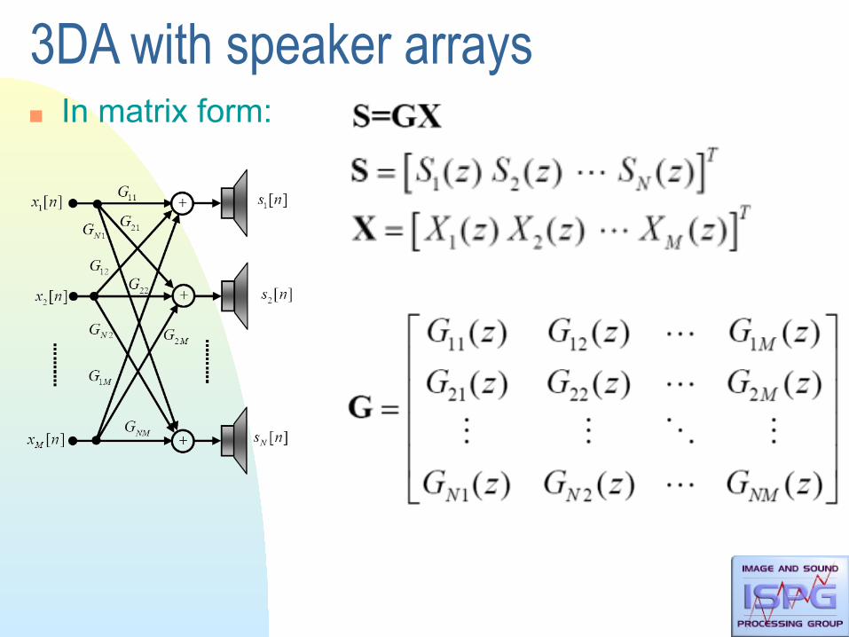
3DA with speaker arrays In matrix form:

3DA with speaker arrays For each speaker, we need to find as many
Transfer Functions as there are sources Auralization problem can be express in finding:
Speakers placement Determination of the network TFs Gij(z).

Speaker placement In principle there are no problems in placing
speakers – Symmetry: guarantees symmetry of the matrix G
We add the TF from speakers to listening points
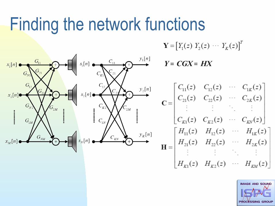
Finding the network functions
Y = CGX = HX

Finding the network functions Network TF determination using Moore-Penrose
pseudo-inverse of C This is usually just a theoretical reference:
– the inversion of C is an ill-posed problem (we almost never have minimum-phase network functions)
– Computationally this is not a viable solution as the impulse response could turn out to be extremely long

Finding the network functions For the calculus for the pseudo-inverse matrix C:
Many approximation are proposed which work in constrained conditions
E.g., Singular Value Decomposition (SVD) – delete singular least significant values and preserve principal components
In practical problem the inversion may be not feasible: We introduce approximations justified from the
perceptive point of view.

Finding the network functions If we consider Gij = gij (we approximate TF with
constant values) we obtain an Amplitude Panning Since gij is constant doesn’t depend on z, and it can
modify only the amplitude Obtained a Spatial model based only on ILD (not
compliant with duplex-theory) A model also based on ITD: we introduce a delay
ILD = Interaural Level Difference ITD = Interaural Time Difference
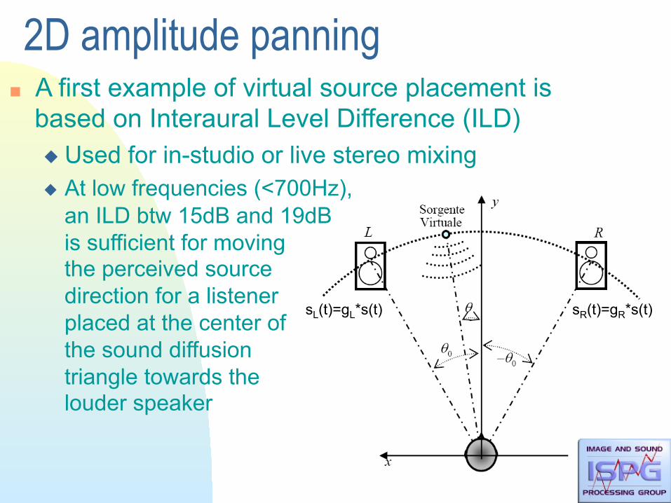
2D amplitude panning A first example of virtual source placement is
based on Interaural Level Difference (ILD) Used for in-studio or live stereo mixing At low frequencies (<700Hz),
an ILD btw 15dB and 19dB is sufficient for moving the perceived source direction for a listener placed at the center of the sound diffusion triangle towards the louder speaker
sL(t)=gL*s(t) sR(t)=gR*s(t)

Amplitude panning This is a special case of the network function
determination seen before In the case of N speakers, if s(t) is the signal to be
distributed over the various speakers, we can write If gR and gL are the gains of the right and left
speaker, respectively, and 2θ is the aperture angle of the speakers (usually 2θ ≈ 60°), there are several possibilities for linking gains to the perceived panning-angle

Amplitude panning
Sine law Tangent law
performs better than sine law based on a circular propagation model around the
listener’s head
Conditions: θ < θ0 F < 500 Hz

Amplitude panning In order to keep the perceived sound level constant
we need to use the constraint
p depends on the environment’s characteristics and decides the level of the virtual source Anechoic environment: p=1
• set the signal amplitude
Reverberating environment: p=2 • set the signal intensity

Amplitude panning Chowning’s amplitude panning law
Let θn and θm be the azimuthally angles of a pair of adjacent speakers, the panning-angle is defined by
Where gm and gn are the m and n speaker gains,
respectively

Vector Base Amplitude Panning Based on the tangent law, VBAP is aimed at positioning a
virtual source anywhere in 3D • Three speakers are not on the same plane (with the listener) • We assume the listener to be at the origin of the axes

VBAP Direction of the n-th speaker (unit vector)
In the case of three speakers we have Panning direction (unit vector) The virtual source direction is a linear combination
of levels and directions of the speakers

VBAP Let Lnmk=[In Im Ik]T be the matrix that contains
the speaker directions, we can rewrite everything in matrix form
Can be extended also for more then 3 speakers

VBAP There are automatic methods for computing g Constraints:
The speakers of a triplet must be non-coplanar L it’s not invertible
Triangles must not overlap When a source pass from a triangle to another
one, 2 speakers remain active The sides of the triangles must be as short as
possible degradation of sound quality

VBAP automatic algorithm
1) all the triangles combinations are formed 2) triangles with small area compared to the length of sides are deleted 3) crossing triangles are searched. Triangles with longer crossing side
are deleted 4) triangles that include loudspeakers are deleted
Creating Auditory Displays with Multiple Loudspeakers Using VBAP: A Case Study with DIVA Project
2
235
345
234
1
145
123124
1341353
1
2
3
5
4
Triangles
145
235245
234
345
1231
23
4
5
Triangles
124
134
345
234
Triangles Triangles
135
123124
345
234
245
4
5
4
1
2
3
5
1
4
123124125134
5
2 3 4
1
2
3
Figure 2: Initial triangularization process for five loudspeakers in 3-D setup. Step 1: All triangles are formed. Step 2:Too narrow triangles are removed. Step 3: Crossing sides are resolved. Step 4: Triangles that include loudspeakers areremoved. The result of the process is seen in the rightmost figure.
small area when compared to total length of sides are deleted. In step 3 all crossings of triangle sides are searched.When a crossing is found, the triangle that includes longer crossing side is removed. The crossing of two trianglesides (lines) is checked using simple vector calculation. Suppose that we want to check if lines between loudspeakersand , and between loudspeakers and cross, as in Fig. 3. The unit-length vectors , and , specify thedirections of the loudspeakers. Both vector pairs and , specify a plane. If the planes cross on thesegment of line connecting the both loudspeaker pairs, the triangle sides cross. The two directions in where theplanes cross is found using equation
(2)
where denotes the vector cross product. If or points to both triangle sides, the sides cross each other. Thisholds if and holds for either or . The operatordenotes the smallest angle between specified two vectors.
-cl
ljc
lni
i
-c
a) b)
l
l
lj
n
c
lm lm
Figure 3: a) The line between vectors and between vectors cross, thus points to both lines b) Thelines do not cross, thus neither nor points to both lines.
In step 4 the triangles that include a loudspeaker are removed. For each triangle all loudspeakers are tested. Thetesting is performed by calculating gain factors to each loudspeaker direction vector using VBAP. The triangle mustbe deleted if all three gain factors of any loudspeaker are positive.
After these four steps a set of triangles is formed. The triangles are non-overlapping, and they have as equal-lengthsides as possible. The triangularization is performed only once, during initialization.
3 Digital Interactive Virtual Acoustics system with multi-channel soundreproduction
TheDigital InteractiveVirtual Acoustics (DIVA) research project has been introduced earlier in ICAD’96 and ICAD’97[7, 8]. The auditory display part of the DIVA system consists of sound source and room acoustics modeling as well
ICAD’98 3

Speaker placement in home systems Quadro-phonic systems

Speaker placement in home systems 3/2+1 systems

Speaker placement in home systems VBAP is a good technique in localization of sound
source with some constrains:
When the virtual sound source is localized at the same position than a loudspeaker, only g of that speaker must be not equal to 0
Given I and J the two nearer speakers to the virtual sound source, only gi and gj must not equal to 0

Precedence effect The listener tends to perceive the source direction
not just using loudness but also delays

Precedence effect The precedence effect interferes with amplitude
panning a listener standing near a speaker will perceive the
sound as coming from that speaker even if its level is lower than that of another speaker fed with the same signal
The listener has to be equidistant to the speakers We can use Precedence effect for sound
spatializaton Precedence-controlled pan

Precedence-controlled pan We insert delay line in the model
Corresponds to a particular case of the previous general scheme with G diagonal

Distance perception Distance is evaluated on the basis of sound
magnitude Sometimes this characteristic can originate
ambiguities because source intensity is not known We have nothing to compare with
Craven’s hypothesis Source distance is perceived
using sound magnitude as well as the ratio btw direct sound and early reflections

Reverberation cue Ratio btw direct sound intensity and reverberation
intensity In a small reverberating environment the diffused
soundfield is nearly constant everywhere, while direct radiation decreases of 6dB every time distance doubles
If we get away from the source, the ratio btw direct radiation and diffused soundfield becomes progressively smaller
Without any Early Reflection (ER) the listener wouldn’t be able to evaluate the distance

Reverberation cue Distance perception is thus possible even with a
mono signal Gerzon scheme: adjusting the ratio btw direct signal
and Early Reflections we can change the perceived source distance
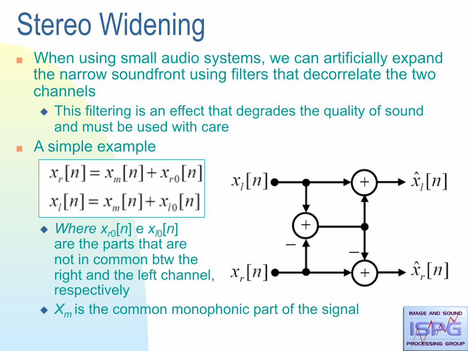
Stereo Widening When using small audio systems, we can artificially expand
the narrow soundfront using filters that decorrelate the two channels This filtering is an effect that degrades the quality of sound
and must be used with care A simple example
Where xr0[n] e xl0[n] are the parts that are not in common btw the right and the left channel, respectively
Xm is the common monophonic part of the signal

Stereo widening The mono component of such signals is thus smaller than
before w.r.t. the stereo component Problems
Interferences btw channels cause acoustic artifacts L+R usually exhibit excess of bass frequencies L-R usually exhibit excess of high frequencies “phasing effects” on the two channels
In order to reduce artifacts it is often necessary to introduce equalizations

General stereo widening problem What mostly affect the spatial impact is the correlation btw the two
channels The more the two channels are correlated, the more the sources is
perceived as one We can devise filters that adjust the level of correlation btw the two
channels P1-P4 can be fixed filters or can depend on the two input signals Good results are achieved when they adapt to some statistical
properties of the input signals

Examples of adaptive schemes Maher method
An analysis of the correlation of the signal produces a control signal (PFACTOR) that adjusts the output gains
P1-P4 are equalizers
correl. analysis
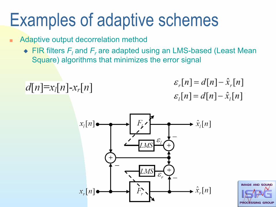
Examples of adaptive schemes Adaptive output decorrelation method
FIR filters Fl and Fr are adapted using an LMS-based (Least Mean Square) algorithms that minimizes the error signal

Pseudo-stereo Minor changes in the described techniques also
allow us to generate stereo signals from mono signals. Here are some trivial examples Use a pair of LP-HP filters and send LF to one
channel and HF to the other Use two comb filters with complementary
characteristics Use a simple delay line (a channel is a delayed
version of the other)

Pseudo-stereo More complex methods use decorrelation based on
phase dispersion Introduce different phase delays on the two
channels, both depending on the frequency Phase decorrelation decreases similarity on the
two channels without introducing perceivable spectral/temporal artifacts A typical scheme uses 5 cascaded all-pass cells
with different coefficients on the two channels

Pseudo-stereo Parameter choices
Recommended