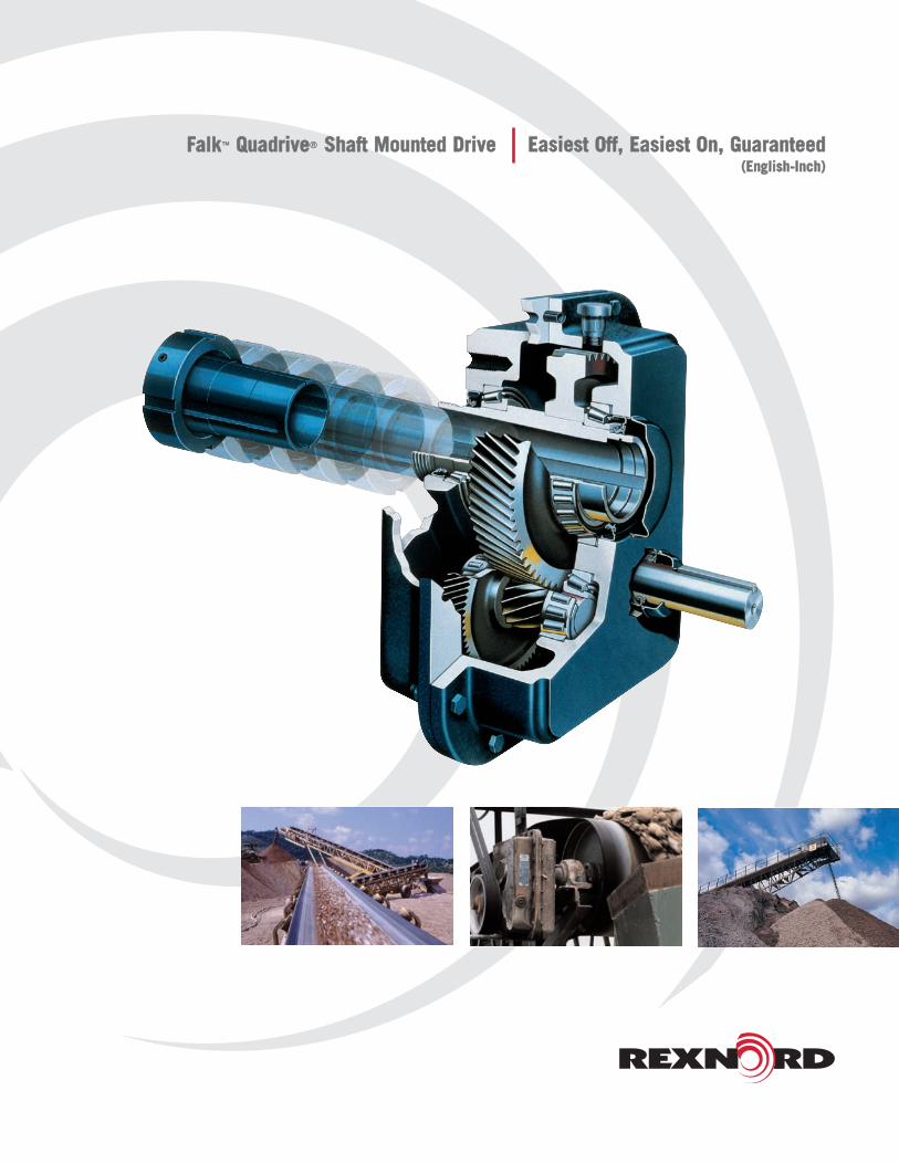
FFaallkk™™ QQuuaaddrriivvee®® SShhaafftt MMoouunntteedd DDrriivvee EEaassiieesstt OOffff,, EEaassiieesstt OOnn,, GGuuaarraanntteeeedd((EEnngglliisshh--IInncchh))

2
Stop Dodging the IssueWith the new Falk 5000 Series Quadrive, you don’t have to turn a
blind eye to drive removal issues. It’s a simple fact. The heavy
duty, shaft-mounted Falk Quadrive features a completely unique
design that makes it the easiest, quickest shaft-mounted drive to
install and remove.
Quadrive is built to stand up to continuous rough duty. High
temperature Viton® seals are standard. And now, with new higher
ratings, you may be able to downsize the drive, saving money right
up front.
The Falk TA Taper® Bushing design makes sure that drive removal
is not only simple, but won’t damage the drive, or driven
equipment. You don’t need extra time. You don’t need extra tools.
And you’re assured safe, worry-free operation.
In a game where there are so few sure things, Falk Quadrive is the
right shot to take.
The TA Taper BushingEasiest On, Easiest OffThe torque-assist taper bushing
makes installation and removal
easy. It eliminates binding found
with twin-taper and single-flanged
bushings.
Concentric operation minimizes
wobble, even on worn shafts.
The quill cover keeps
contaminants out and protects the
outboard shaft seal.
The inboard bushing location
minimizes sheave overhang,
saving high-speed bearings.
Minimal shaft engagement is
required for retrofits.b
Lifetime Removal GuaranteeDue to the unique properties of
the TA Taper® Bushing, Quadrive
is guaranteed to come off the
shaft, regardless of length of
service or operating conditions, or
we’ll replace it FREE. That’s a
promise no other shaft-mounted
drive can make.
KEY
THREADED NUT
SET SCREWLOCATION TA
REMOVALTOOL
THREADS
TA TAPEREDBUSHING
RETAININGRING
3
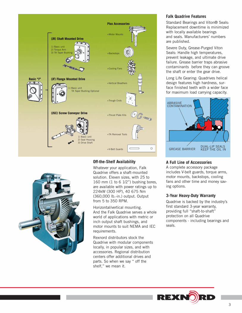
Off-the-Shelf AvailabilityWhatever your application, Falk
Quadrive offers a shaft-mounted
solution. Eleven sizes, with 25 to
160 mm (1 to 6 1/2”) bushing bores,
are available with power ratings up to
224kW (300 HP), 40 675 Nm
(360,000 lb.-in.) output. Output
from 5 to 350 RPM.
Horizontal/vertical mounting.
And the Falk Quadrive serves a whole
world of applications with metric or
inch output shaft bushings, and
motor mounts to suit NEMA and IEC
requirements.
Rexnord distributors stock the
Quadrive with modular components
locally, in popular sizes, and with
accessories. Regional distribution
centers offer additional drives and
parts. So when we say “ off the
shelf,” we mean it.
Falk Quadrive FeaturesStandard Bearings and Viton® Seals:
Replacement downtime is minimized
with locally available bearings
and seals. Manufacturers’ numbers
are published.
Severe Duty, Grease-Purged Viton
Seals: Handle high temperatures,
prevent leakage, and ultimate drive
failure. Grease barrier traps abrasive
contaminants before they can groove
the shaft or enter the gear drive.
Long Life Gearing: Quadrives helical
design features high hardness, sur-
face finished teeth with a wider face
for maximum load carrying capacity.
A Full Line of AccessoriesA complete accessory package
includes V-belt guards, torque arms,
motor mounts, backstops, cooling
fans and other time and money sav-
ing options.
3-Year Heavy-Duty WarrantyQuadrive is backed by the industry’s
first standard 3-year warranty,
providing full “shaft-to-shaft”
protection on all Quadrive
components - including bearings and
seals.
GREASE BARRIERDUAL-LIP SEALSKEEP THE OIL IN
ABRASIVECONTAMINATION
((JJRR)) SShhaafftt MMoouunntteedd DDrriivvee
1) Basic unit
2) Seal Housing
3) Drive Shaft
+Backstops
+Motor Mounts
+Cooling Fans
+Vertical Breathers
+Trough Ends
+Thrust Plate Kits
+TA Removal Tools
+V-Belt Guards
1) Basic unit
TA Taper Bushing Optional
PPlluuss AAcccceessssoorriieess
((JJFF)) FFllaannggee MMoouunntteedd DDrriivveeBBaassiicc ““JJ””
((JJSSCC)) SSccrreeww CCoonnvveeyyoorr DDrriivvee
1) Basic unit
2) Torque Arm
3) TA Taper Bushing

4
Quadrive Shaft-Mounted DrivesSelection Guide

Table of ContentsBasic Information & Conditions Affecting Selections . . . . . . . . 5-6How to Select & Order . . . . . . . . . . . . . . . . . . . . . . . . . . . . 7-8Load Classifications . . . . . . . . . . . . . . . . . . . . . . . . . . . . . . . . 9Class I, II & III Selection Tables . . . . . . . . . . . . . . . . . . . . 10-12Engineering Data . . . . . . . . . . . . . . . . . . . . . . . . . . . . . . 13-155107JR, JF & JSC Dimensions & Part Numbers . . . . . . . . . 16-175115JR, JF & JSC Dimensions & Part Numbers . . . . . . . . . 18-195203JR, JF & JSC Dimensions & Part Numbers . . . . . . . . . 20-215207JR, JF & JSC Dimensions & Part Numbers . . . . . . . . . 22-235215JR, JF & JSC Dimensions & Part Numbers . . . . . . . . . 24-255307JR, JF & JSC Dimensions & Part Numbers . . . . . . . . . 26-275315JR, JF & JSC Dimensions & Part Numbers . . . . . . . . . 28-295407JR, JF & JSC Dimensions & Part Numbers . . . . . . . . . 30-335415JR & JF Dimensions & Part Numbers . . . . . . . . . . . . . 34-355507JR & JF Dimensions & Part Numbers . . . . . . . . . . . . . 36-375608JR & JF Dimensions & Part Numbers . . . . . . . . . . . . . 38-40Trough End Dimensions & Part Numbers . . . . . . . . . . . . . . . . 41Stainless Steel Drive Shafts & Part Numbers . . . . . . . . . . . . . . 41Taper Conversion Bushing (TCB) Kits & Part Numbers . . . . . . . 41Nominal Sheave Ratios & V-Belts . . . . . . . . . . . . . . . . . . . . . . 42V-Belt Guard Selections . . . . . . . . . . . . . . . . . . . . . . . . . . 43-45Electric Fan Dimensions & Part Numbers . . . . . . . . . . . . . . 46-47Motor Mount Shaft Centers & Motor Frame Sizes . . . . . . . . . . 48Accessories/Options . . . . . . . . . . . . . . . . . . . . . . . . . . . . . . . 49Suggested Drive Arrangement–Non Falk™ Motor Mount . . . . . 50
Factory Warranty We’re so confident in the performance andreliability of our latest generation of Falk™ gear drives that we’rebacking this comprehensive offering with the best standard warranty inthe business. Our full, 3-year Heavy-Duty Warranty provides“shaft-to-shaft” protection on all Falk™ components – includingbearings and seals. It’s an industry first... and one more powerfulreason why Rexnord is your ultimate bottom-line gear drive andcoupling value.�
Basic InformationSafety NotesFalk™ Gear Drives — The Falk and Rexnord name on the geardrive is the purchaser's assurance that the drive was engineered, ratedand manufactured to sound design practices.
When one prime mover drives two pieces of equipment, one of whichis either a standard Falk geared drive or a customer standard geareddrive, the division of power between each machine is the responsibilityof the customer. The power supplied to the geared drive must beequal to or less than the power for which the drive was selected usingthe appropriate service factor for the application. The customer mustalso assume the responsibility of isolating the geared drive from anyvibratory or transient load induced by the driven equipment.
Install and operate Rexnord products in conformance withapplicable local and national safety codes and per Rexnordowner's manual which is available upon request. Suitable guardsfor rotating members may be purchased from Rexnord as optional
accessories. Consult your local Rexnord Account Executive forcomplete details.
People Conveying Equipment — Selection of Rexnord gear drives forapplications whose primary purpose is the transportation of people is notapproved. This includes such applications as freight or passengerelevators, escalators, man lifts, work lift platforms and ski tows and ski lifts.
If the primary purpose of the application is material conveyanceand occasionally people are transported, the Rexnord warrantymay remain in effect provided the design load conditions are notexceeded and certification to the appropriate safety codes andload conditions has been obtained by the system designer or enduser from the appropriate enforcement authorities.
Gear Drive RatingsShaft Mounted, Flange Mounted and Screw Conveyor Drives arerated to a specific application by the use of Load Classifications.Each application has its own conditions and operatingrequirements. These have been analyzed and catalogued intothree load classifications . . . uniform, moderate shock and heavyshock. Load classifications, based on field experience, have beenassigned to these applications for service of 3 to 10 hours per day,and for service over 10 hours per day, and also for the type ofprime mover. Values for most applications are listed on Page 9.Refer unlisted applications to Factory.
Load Classifications are based on the assumption that the systemis free of dynamic vibrations, as explained in the warranty section.Refer applications subject to repetitive shocks and applicationswhere exceedingly high energy load must be absorbed, as whenstalling, to Factory for special consideration.
Operating Temperature — Gear drives can encounter sump oiltemperatures up to 200°F (93°C). Higher temperatures arepossible in localized areas. Since the drive will feel hot to thehuman hand at temperatures over 120°F (49°C), a portablepyrometer should be used to measure temperatures. Some drives,as indicated in the selection tables, are furnished with fans toensure satisfactory operating temperatures.
Conditions Affecting Gear Drive Selection and Application —The following conditions may affect the drive selection procedure,drive size and auxiliary equipment being furnished. Refer to Page 6for more information.� Excessive Overloads� Reversing Service� Brake Equipped Applications� Oversized Prime Movers� Multi-Speed or Variable Speed Applications� Excessive Ambient Temperatures� Excessive Overhung Loads or Thrust Loads� Non-Standard Mounting Positions� Product Modification� BackstopsStored & Inactive Drives — Each gear drive is spin-tested with arust preventive oil that will protect parts against rust for a period offour months in an outdoor shelter or twelve months in dry buildingafter shipment from Rexnord.
Periodically inspect stored or inactive drives and spray or add rustinhibitor every six months or more often, if necessary. Indoor drystorage is recommended.
Drives ordered for extended storage can be treated at the Factorywith a special preservative and sealed to rustproof parts forperiods longer than those cited above, if specified on the order.
Refer to appropriate service manual for extended storage of geardrives which have been in service.
© Rexnord Industries, LLC, 1979, 2007. (371-110) 5
Selection Guide 371-110, February 2007
Copyright 1979, 2007. Rexnord Industries, LLC. Gear Group
EQUI-POISED, LIFELIGN, OMNIBOX, QUADRIVE, RENEW, REXNORD, STEELFLEX, TA TAPER,TORUS, and ULTRAMITE, are registered trademarks of Rexnord Industries, LLC. Falk is a trademarkof Rexnord. All Rights Reserved. Litho in USA.
The contents of this selection guide are subject to change without notice or obligation. Informationcontained herein should be confirmed before placing orders.
� Warranty extends for 3 years from date of shipment.
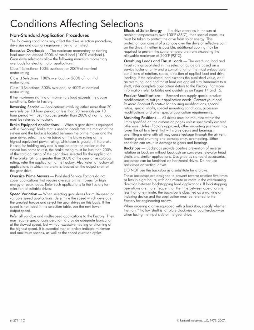
Non-Standard Application ProceduresThe following conditions may affect the drive selection procedure,drive size and auxiliary equipment being furnished.
Excessive Overloads — The maximum momentary or startingload must not exceed 200% of rated load ( 100% overload ).Gear drive selections allow the following minimum momentaryoverloads for electric motor applications:
Class I Selections: 100% overload, or 200% of nominalmotor rating.
Class II Selections: 180% overload, or 280% of nominalmotor rating.
Class lIl Selections: 300% overload, or 400% of nominalmotor rating.
If the maximum starting or momentary load exceeds the aboveconditions, Refer to Factory.
Reversing Service — Applications involving either more than 20reversals per 10 hour period, or less than 20 reversals per 10hour period with peak torques greater than 200% of normal loadmust be referred to Factory.
Brake Equipped Applications — When a gear drive is equippedwith a “working” brake that is used to decelerate the motion of thesystem and the brake is located between the prime mover and thegear drive, select the drive based on the brake rating or thehighest equivalent power rating, whichever is greater. If the brakeis used for holding only and is applied after the motion of thesystem has come to rest, the brake rating must be less than 200%of the catalog rating of the gear drive selected for the application.If the brake rating is greater than 200% of the gear drive catalograting, refer the application to the Factory. Also Refer to Factory allapplications in which the brake is located on the output shaft ofthe gear drive.
Oversize Prime Movers — Published Service Factors do notcover applications that require oversize prime movers for highenergy or peak loads. Refer such applications to the Factory forselection of suitable drives.
Speed Variation — When selecting gear drives for multi-speed orvariable speed applications, determine the speed which developsthe greatest torque and select the gear drives on this basis. If thespeed is not listed in the selection table, use the next loweroutput speed.
Refer all variable and multi-speed applications to the Factory. Theymay require special consideration to provide adequate lubricationat the slowest speed, but without excessive heating or churning atthe highest speed. It is essential that all orders indicate minimumand maximum speeds, as well as the speed duration cycles.
Effects of Solar Energy — If a drive operates in the sun atambient temperatures over 100°F (38°C), then special measuresmust be taken to protect the drive from solar energy. Thisprotection can consist of a canopy over the drive or reflective painton the drive. If neither is possible, additional cooling may berequired to prevent the sump temperature from exceeding theallowable maximum of 200°F (93°C).
Overhung Loads and Thrust Loads — The overhung load andthrust ratings published in this selection guide are based on aservice factor of unity and a combination of the most unfavorableconditions of rotation, speed, direction of applied load and driveloading. If the calculated load exceeds the published value, or ifan overhung load and thrust load are applied simultaneously to ashaft, refer complete application details to the Factory. For moreinformation refer to tables and guidelines on Pages 14 and 15.
Product Modifications — Rexnord can supply special productmodifications to suit your application needs. Contact your localRexnord Account Executive for housing modifications, specialratios, special shafts, special mounting conditions, accessorymodifications and other special application requirements.
Mounting Positions — All drives must be mounted within thelimits specified on the dimension pages unless specifically orderedotherwise. Unless Factory approved, other mounting positions maylower the oil to a level that will starve gears and bearings;overfilling a drive with oil may cause leakage through the air vent,foaming and churning and consequently, overheating. Eithercondition can result in damage to gears and bearings.
Backstops — Backstops provide positive prevention of reverserotation or backrun without backlash on conveyors, elevator headshafts and similar applications. Designed as standard accessories,backstops can be furnished on horizontal drives. Do not usebackstops on vertical drives.
DO NOT use the backstop as a substitute for a brake.
These backstops are designed to prevent reverse rotation five timesor less in eight hours, with one minute or more in the overrunningdirection between backstopping load applications. If backstoppingoperations are more frequent, or the time between operations isless than one minute, the backstop is classified as a working orindexing device and the application must be referred to theFactory for engineering review.
When ordering a drive equipped with a backstop, specify whetherthe Falk™ hollow shaft is to rotate clockwise or counterclockwisewhen facing the input side of the gear drive.
6 (371-110) © Rexnord Industries, LLC, 1979, 2007.
Conditions Affecting Selections

1. Information required.� Driven machine
� Motor horsepower/rpm/frame size
� Hours/day operation
� Driven shaft diameter/rpm
� Mounting requirements/space limits
If you have an unusual application involving any of the followingconditions, refer to Page 6.
� Excessive overloads
� Reversing service
� Brake equipped applications
� Oversized prime movers
� Multi-speed or variable speed applications
� Excessive ambient temperatures
� Excessive overhung loads or thrust loads
� Product modifications
� Non-standard mounting positions2. Drive selection.
Determine load classification based on the application fromTable 1, Page 9. Refer to Class I, II or III Selection Tables onPages 10 thru 12. Select basic gear drive size and ratioopposite desired horsepower and output speed (Note theminimum high speed shaft sheave pitch diameter). Determinedrive Type JR (Shaft Mounted Drive), JF (Flange Mounted Drive)or JSC (Screw Conveyor Drive). Also check the overhung loadand thrust load. Thermal capacities in selection tables arebased on 80°F(27°C) ambient. If ambient temperature exceedsthis value, Refer to Factory.
The selection tables show the most economical drive ratio for agiven speed. If a different drive ratio is required to meetapplication or delivery requirements, refer to the RatioSubstitution Table on Page 13.
3. Check dimensions.Refer to drive size dimension pages and check TA taperbushing bore, mounting position, clearances, and motor mount& motor frame size details.
4. Sheave ratios.Nominal sheave ratios are given in Table 12, on Page 42.Select final V-belt to suit the motor mount center distance andcompare the driven sheave pitch diameter to the minimumdetermined in the selection table.
Example1. Application Details
Uniformly loaded inclined belt conveyor.20 Horsepower, 1750 rpm motor, 256 T frame.10 Hours/day operation.211/16” Diameter head shaft at 44 rpm.Shaft mounted drive/horizontal.
2. The Load Classification from Table 1, on Page 9, is Class I.From the Class I selection, Table 2, on Page 10, opposite 20hp and output range of 60-37 rpm, the drive size is5215J_25A with a minimum H.S. sheave pitch diameter of6.0”. Drive type is a “JR” shaft mounted drive.
3. Refer to Pages 24 and 25 to check drive dimension data. Ahollow shaft Bushing No. BU5215J-2.688, Part No. 0769143is required to fit the drive to the 211/16” diameter headshaft. A6-o'clock mounting position is required. The motor mountcenter distance range available is 24.8-37.2”, with a 256Tframe motor.
4. From Table 12, on Page 42, the nominal sheave ratio is 1.59for a 25:1 ratio drive with a 1750 rpm motor, at 44 rpmoutput. Select the V-belt drive to suit the available centerdistance range (short, medium or long). Be sure to allow forbelt take up. Also, verify that the driven sheave pitch diameteris larger than the minimum specified.
Order:
Basic Drive 5215JR25A PN 0794385
Bushing BU5215J-2.688 PN 0769143
Torque Arm TA52157J PN 0785267
Motor Mount MM5215J-2 PN 0786261
Backstop BS5215J05/09/14/25 PN 0785610Clockwise rotation
V-Belt Guard
© Rexnord Industries, LLC, 1979, 2007. (371-110) 7
How to Select

AccessoriesMotor Mount—Description/Motor Frame Size (PN)Backstop—Description/L.S. Rotation Viewing Input Side (PN) (Not available on vertical drives.)Shaft Cooling Fan—Specify on Order/Factory Installed (5215-5608J only)Electric Fan—Description (PN)/Specify Fan Mounting Position (5407-5608J) If Factory InstalledVertical Breather—Description/H.S. Shaft Up or Down (PN)Trough End—Description (PN)Thrust Plate Kit—Description (PN)TA Removal Tool—Description (PN)V-Belt Guard—Description (PN)TCB (Taper Conversion Bushing)—Description (PN)
Contact Factory for special design options.
8 (371-110) © Rexnord Industries, LLC, 1979, 2007.
How to OrderThe following information is required to quote or ship to your requirements.
Sizes 5107 thru 5315� JR Shaft Mounted Drive
1. Basic Drive/Ratio (PN)
2. Bushing Size/Bore (PN)
3. Torque Arm (PN)
Sizes 5407 thru 5608� JR Shaft Mounted Drive
1. Drive/Ratio (PN)
Torque Arm Included
2. Bushing Size/Bore (PN)
� JF Flange Mounted Drive
1. Basic Drive/Ratio (PN)
Bushing Size/Bore (PN)— Optional
(See Manual 377-142)
� JF Flange Mounted Drive
1. Drive/Ratio (PN)Flange Included
Bushing Size/Bore (PN)— Optional
(See Manual 377-144)
� JSC Screw Conveyor Drive
1. Basic Drive/Ratio (PN)
2. Seal Housing (PN)
Seal Options (PN)
3. Drive Shaft Dia. (PN)
Thrust Plate Kit Included
� JSC Screw Conveyor Drive (5407 only)
1. Drive/Ratio (PN)
Seal Housing Included
2. Drive Shaft Dia. (PN)
Thrust Plate Kit Included
DRIVE NOMENCLATURE
5 107 JR 25 AModel
5000 Series Nominal Drive Ratio
Max Bushing Bore Dia. Drive Type
107 = 1 7/16” 315 = 3 15/16” J = Basic Drive (Sizes 5107-5315)
115 = 1 15/16” 407 = 4 7/16” JR = Shaft Mounted Drive (Horizontal)
203 = 2 3/16” 415 = 4 15/16” JRV = Shaft Mounted Drive (Vertical)
207 = 2 7/16” 507 = 5 7/16” JF = Flange Mounted Drive (Horizontal)
215 = 2 15/16” 608 = 6 1/2” JFV = Flange Mounted Drive (Vertical)
307 = 3 7/16” JSC = Screw Conveyor Drive (Horizontal) (Sizes 5107-5407)

© Rexnord Industries, LLC, 1979, 2007. (371-110) 9
Load Classifications �. . . Electric Motor Driven Applications
Recommendations are minimum and normal conditions are assumed.
Service
APPLICATION 3 to Over
10 10
Hour Hour
AGITATORSPaper Mill (Mixers) . . . . . . . . . . . II IIPure Liquids. . . . . . . . . . . . . . . . I IISemi-Liquids, Variable . . . . . . . .
Density . . . . . . . . . . . . . . . . . II II
APRON CONVEYORSUniformly Loaded . . . . . . . . . . . I IIHeavy Duty . . . . . . . . . . . . . . . . II III
ASSEMBLY CONVEYORSUniformly Loaded . . . . . . . . . . . I IIHeavy Duty . . . . . . . . . . . . . . . . II II
BELT CONVEYORSUniformly Loaded . . . . . . . . . . . I IIHeavy Duty . . . . . . . . . . . . . . . . II II
BREWING & DISTILLINGBottling Machinery . . . . . . . . . . . I IIBrew Kettles, Continuous . . . . . . ... IICan Filling Machines . . . . . . . . . I IICookers, Continuous . . . . . . . . . ... IIMash Tubs, Continuous . . . . . . . ... IIScale Hoppers, Frequent
Starts . . . . . . . . . . . . . . . . . II II
BUCKETConveyors Heavy Duty . . . . . . . . II IIElevators, Uniform Load . . . . . . . I IIElevators, Heavy Duty. . . . . . . . . II III
CAN FILLING MACHINES . . . . . I II
CARDumpers . . . . . . . . . . . . . . . . . . III ...Pullers . . . . . . . . . . . . . . . Refer to Factory
CLARIFIERS . . . . . . . . . . . . . . . . I II
CLASSIFIERS. . . . . . . . . . . . . . . . II II
CLAY WORKINGMACHINERYBrick Presses . . . . . . . . . . . . . . . III IIIBriquette Machines . . . . . . . . . . III IIIExtruders & Mixers . . . . . . . . . . . II III
CONVEYORS—UNIFORMLYLOADED OR FED †
Apron and Assembly . . . . . . . . . I II
Service
APPLICATION 3 to Over
10 10
Hour HourBelt. . . . . . . . . . . . . . . . . . . . . . I IIFlight . . . . . . . . . . . . . . . . . . . . II IIOven . . . . . . . . . . . . . . . . . . . . I IILive Roll (Package) . . . . . . . . . . . I IIScrew . . . . . . . . . . . . . . . . . . . . I IITable—See Metal Mills . . . . . . . ... ...
CONVEYORS—HEAVY DUTY—NOT UNIFORMLY FED ‡
Apron . . . . . . . . . . . . . . . . . . . . II IIIAssembly. . . . . . . . . . . . . . . . . . II IIBelt. . . . . . . . . . . . . . . . . . . . . . II IIBucket or Pan . . . . . . . . . . . . . . II IIFlight . . . . . . . . . . . . . . . . . . . . II IILive Roll . . . . . . . . . . . . . . Refer to FactoryOven . . . . . . . . . . . . . . . . . . . . II IIReciprocating . . . . . . . . . . . . . . III IIIScrew . . . . . . . . . . . . . . . . . . . . II IITable—See Metal Mills . . . . . . . ... ...
CRANES & HOISTS ‡
Bridge and Trolley Drive . . . . . . . II IICUTTER HEAD DRIVES . . . . . . Refer to Factory
DISTILLING — See Brewing . . . . . ... ...
DRYERS & COOLERS,ROTARY
II III
ELEVATORSBucket—Unifarm Load . . . . . . . . I IIBucket—Heavy Load . . . . . . . . . II IIIEscalators‡ . . . . . . . . . . . . . . . . Not ApprovedFreight‡ . . . . . . . . . . . . . . . . . . Not ApprovedMan lifts, Passenger‡ . . . . . . . . . Not Approved
FLIGHT CONVEYORSUniformly Loaded . . . . . . . . . . . II IIHeavy Duty . . . . . . . . . . . . . . . . II II
FOOD INDUSTRYBeet Slicers . . . . . . . . . . . . . . . . II IICan Filling Machines . . . . . . . . . I IICereal Cookers . . . . . . . . . . . . . I IIDough Mixers . . . . . . . . . . . . . . II IIMeat Grinders . . . . . . . . . . . . . . II ll
LAUNDRYWashers, reversing. . . . . . . Refer to FactoryTumblers. . . . . . . . . . . . . . . . . . II III
Service
APPLICATION 3 to Over
10 10
Hour Hour
LINE SHAFTSUniform Load . . . . . . . . . . . . . . I IIHeavy Load. . . . . . . . . . . . . . . . II II
LIVE ROLL CONVEYORSUniformly Loaded, Package . . . . I IIHeavy Duty . . . . . . . . . . . . Refer to Factory
MACHINE TOOLSAuxiliary Drives . . . . . . . . . . . . . I IIMain Drives Uniform Load . . . . . II IIMain Drives Heavy Load. . . . . . . III III
METAL MILLSTable Conveyors,
Non Reversing . . . . . . . . . . II IIIReversing. . . . . . . . . . . . Refer to Factory
Wire Drawing & FlatteningMachines . . . . . . . . . . . . . . II III
MILLS(See Metal Mills)Pebble . . . . . . . . . . . . . . . . . . . II III
MIXERS (See Agitators)Concrete, Continuous . . . . . . . . II IIIConcrete, Intermittent. . . . . . . . . II ...Constant Density . . . . . . . . . . . . I IIVariable Density. . . . . . . . . . . . . II IILiquid . . . . . . . . . . . . . . . . . . . . I IIPaper Mill (Agitators) . . . . . . . . . II IISemi-Liquid . . . . . . . . . . . . . . . . II II
OVEN CONVEYORSUniformly Loaded . . . . . . . . . . . I IIHeavy Duty . . . . . . . . . . . . . . . . II II
PAN CONVEYORSHeavy Duty . . . . . . . . . . . . . . . . II II
PAPER MILLSAgitators (Mixers) . . . . . . . . . . . . II IIBleachers . . . . . . . . . . . . . . . . . I IICalenders . . . . . . . . . . . . . . . . . ... IIICylinders. . . . . . . . . . . . . . . . . . ... IIFelt Stretchers . . . . . . . . . . . . . . ... IIWinders . . . . . . . . . . . . . . . . . . ... II
PEBBLE MILLS . . . . . . . . . . . . . . . II III
Service
APPLICATION 3 to Over
10 10
Hour Hour
PUMPSProportioning. . . . . . . . . Refer to Factory
Reciprocating, openDischarge. . . . . . . . . . . . . . I II
Double ActingMulti-Cylinder . . . . . . . . . . . II IIISingle Cylinder. . . . . . . . Refer to Factory
Rotary (Gear Type)Constant Density . . . . . . . . . I IIVariable Density . . . . . . . . . II II
RECIPROCATINGConveyors. . . . . . . . . . . . . . . . . III III
RUBBER INDUSTRYTire Building Machines . . . . . . . . II IITire & Tube Press Openers . . . . . I I
SCREENSAir Washing . . . . . . . . . . . . . . . I IIRotary, Stone or Gravel . . . . . . . II IITraveling Water Intake . . . . . . . . I IIShaker . . . . . . . . . . . . . . . . . . . II III
SCREW CONVEYORSUniformly Loaded . . . . . . . . . . . I IIHeavy Duty . . . . . . . . . . . . . . . . II II
SKI TOWS & LIFTS ‡ . . . . . . . . . Not Approved
SKIP HOISTS ‡ . . . . . . . . . . . . . . II ...
STOKERS . . . . . . . . . . . . . . . . . . ... II
TEXTILE INDUSTRYBatchers . . . . . . . . . . . . . . . . . . II IICalenders . . . . . . . . . . . . . . . . . II IICard Machines . . . . . . . . . . . . . III IIIDry Cans. . . . . . . . . . . . . . . . . . II IIDyeing Machinery . . . . . . . . . . . II IILooms . . . . . . . . . . . . . . . Refer to FactoryMangles, Nappers & Soapers . . . II IISpinners . . . . . . . . . . . . . . . . . . II IIITenter Frames . . . . . . . . . . . . . . II II
TUMBLING BARRELS . . . . . . . . . III III
WINDLASS . . . . . . . . . . . . . . . . . II III
TABLE 1
� LOAD CLASSIFICATIONS FOR ENGINE-DRIVEN APPLICATIONS — Multi-Cylinder Engines: Use the next higher Service Class than the one given in Table 1 for the sameapplication when motor driven. (Example: A motor-driven uniformly loaded belt conveyor for 10 hour service is Class I; the same conveyor driven by a multi-cylinder enginewould be Class II). For applications which require Class III when motor driven, Refer to Factory for recommendations on engine drives. Single Cylinder Engines: Refer toFactory.
‡ Selection of Falk™ products for applications whose primary purpose is the transportation of people is not approved. This includes such applications as freight or passengerelevators, escalators, man lifts, fork lift platforms and ski tows and ski lifts. If the primary purpose of the application is material conveyance and occasionally people aretransported, the warranty may remain in effect provided the design load conditions are not exceeded and certification to the appropriate safety codes and load conditions hasbeen obtained by the system designer or end user from the appropriate enforcement authorities.
10 (371-110) © Rexnord Industries, LLC, 1979, 2007.
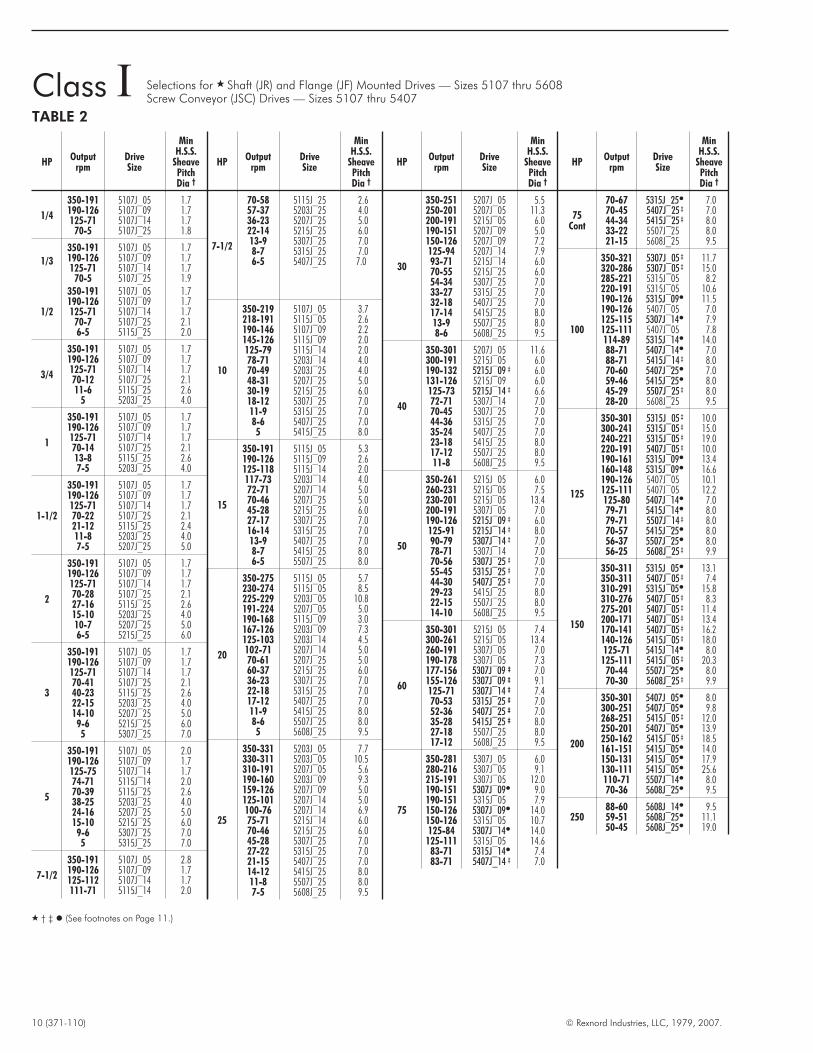
Class I Selections for � Shaft (JR) and Flange (JF) Mounted Drives — Sizes 5107 thru 5608Screw Conveyor (JSC) Drives — Sizes 5107 thru 5407
TABLE 2
HPOutput
rpmDriveSize
MinH.S.S.
SheavePitchDia †
1/4
350-191 5107J_05 1.7190-126 5107J_09 1.7125-71 5107J_14 1.770-5 5107J_25 1.8
1/3
350-191 5107J_05 1.7190-126 5107J_09 1.7125-71 5107J_14 1.770-5 5107J_25 1.9
1/2
350-191 5107J_05 1.7190-126 5107J_09 1.7125-71 5107J_14 1.770-7 5107J_25 2.16-5 5115J_25 2.0
3/4
350-191 5107J_05 1.7190-126 5107J_09 1.7125-71 5107J_14 1.770-12 5107J_25 2.111-6 5115J_25 2.6
5 5203J_25 4.0
1
350-191 5107J_05 1.7190-126 5107J_09 1.7125-71 5107J_14 1.770-14 5107J_25 2.113-8 5115J_25 2.67-5 5203J_25 4.0
1-1/2
350-191 5107J_05 1.7190-126 5107J_09 1.7125-71 5107J_14 1.770-22 5107J_25 2.121-12 5115J_25 2.411-8 5203J_25 4.07-5 5207J_25 5.0
2
350-191 5107J_05 1.7190-126 5107J_09 1.7125-71 5107J_14 1.770-28 5107J_25 2.127-16 5115J_25 2.615-10 5203J_25 4.010-7 5207J_25 5.06-5 5215J_25 6.0
3
350-191 5107J_05 1.7190-126 5107J_09 1.7125-71 5107J_14 1.770-41 5107J_25 2.140-23 5115J_25 2.622-15 5203J_25 4.014-10 5207J_25 5.0
9-6 5215J_25 6.05 5307J_25 7.0
5
350-191 5107J_05 2.0190-126 5107J_09 1.7125-75 5107J_14 1.774-71 5115J_14 2.070-39 5115J_25 2.638-25 5203J_25 4.024-16 5207J_25 5.015-10 5215J_25 6.09-6 5307J_25 7.05 5315J_25 7.0
7-1/2
350-191 5107J_05 2.8190-126 5107J_09 1.7125-112 5107J_14 1.7111-71 5115J_14 2.0
HPOutput
rpmDriveSize
MinH.S.S.
SheavePitchDia †
7-1/2
70-58 5115J_25 2.657-37 5203J_25 4.036-23 5207J_25 5.022-14 5215J_25 6.013-9 5307J_25 7.08-7 5315J_25 7.06-5 5407J_25 7.0
10
350-219 5107J_05 3.7218-191 5115J_05 2.6190-146 5107J_09 2.2145-126 5115J_09 2.0125-79 5115J_14 2.078-71 5203J_14 4.070-49 5203J_25 4.048-31 5207J_25 5.030-19 5215J_25 6.018-12 5307J_25 7.011-9 5315J_25 7.08-6 5407J_25 7.05 5415J_25 8.0
15
350-191 5115J_05 5.3190-126 5115J_09 2.6125-118 5115J_14 2.0117-73 5203J_14 4.072-71 5207J_14 5.070-46 5207J_25 5.045-28 5215J_25 6.027-17 5307J_25 7.016-14 5315J_25 7.013-9 5407J_25 7.08-7 5415J_25 8.06-5 5507J_25 8.0
20
350-275 5115J_05 5.7230-274 5115J_05 8.5225-229 5203J_05 10.8191-224 5207J_05 5.0190-168 5115J_09 3.0167-126 5203J_09 7.3125-103 5203J_14 4.5102-71 5207J_14 5.070-61 5207J_25 5.060-37 5215J_25 6.036-23 5307J_25 7.022-18 5315J_25 7.017-12 5407J_25 7.011-9 5415J_25 8.08-6 5507J_25 8.05 5608J_25 9.5
25
350-331 5203J_05 7.7330-311 5203J_05 10.5310-191 5207J_05 5.6190-160 5203J_09 9.3159-126 5207J_09 5.0125-101 5207J_14 5.0100-76 5207J_14 6.975-71 5215J_14 6.070-46 5215J_25 6.045-28 5307J_25 7.027-22 5315J_25 7.021-15 5407J_25 7.014-12 5415J_25 8.011-8 5507J_25 8.07-5 5608J_25 9.5
HPOutput
rpmDriveSize
MinH.S.S.
SheavePitchDia †
30
350-251 5207J_05 5.5250-201 5207J_05 11.3200-191 5215J_05 6.0190-151 5207J_09 5.0150-126 5207J_09 7.2125-94 5207J_14 7.993-71 5215J_14 6.070-55 5215J_25 6.054-34 5307J_25 7.033-27 5315J_25 7.032-18 5407J_25 7.017-14 5415J_25 8.013-9 5507J_25 8.08-6 5608J_25 9.5
40
350-301 5207J_05 11.6300-191 5215J_05 6.0190-132 5215J_09 ‡ 6.0131-126 5215J_09 6.0125-73 5215J_14 ‡ 6.672-71 5307J_14 7.070-45 5307J_25 7.044-36 5315J_25 7.035-24 5407J_25 7.023-18 5415J_25 8.017-12 5507J_25 8.011-8 5608J_25 9.5
50
350-261 5215J_05 6.0260-231 5215J_05 7.5230-201 5215J_05 13.4200-191 5307J_05 7.0190-126 5215J_09 ‡ 6.0125-91 5215J_14 ‡ 8.090-79 5307J_14 ‡ 7.078-71 5307J_14 7.070-56 5307J_25 ‡ 7.055-45 5315J_25 ‡ 7.044-30 5407J_25 ‡ 7.029-23 5415J_25 8.022-15 5507J_25 8.014-10 5608J_25 9.5
60
350-301 5215J_05 7.4300-261 5215J_05 13.4260-191 5307J_05 7.0190-178 5307J_05 7.3177-156 5307J_09 ‡ 7.0155-126 5307J_09 ‡ 9.1125-71 5307J_14 ‡ 7.470-53 5315J_25 ‡ 7.052-36 5407J_25 ‡ 7.035-28 5415J_25 ‡ 8.027-18 5507J_25 8.017-12 5608J_25 9.5
75
350-281 5307J_05 6.0280-216 5307J_05 9.1215-191 5307J_05 12.0190-151 5307J_09� 9.0190-151 5315J_05 7.9150-126 5307J_09� 14.0150-126 5315J_05 10.7125-84 5307J_14� 14.0125-111 5315J_05 14.683-71 5315J_14� 7.483-71 5407J_14 ‡ 7.0
HPOutput
rpmDriveSize
MinH.S.S.
SheavePitchDia †
75Cont
70-67 5315J_25� 7.070-45 5407J_25 ‡ 7.044-34 5415J_25 ‡ 8.033-22 5507J_25 8.021-15 5608J_25 9.5
100
350-321 5307J_05 ‡ 11.7320-286 5307J_05 ‡ 15.0285-221 5315J_05 8.2220-191 5315J_05 10.6190-126 5315J_09� 11.5190-126 5407J_05 7.0125-115 5307J_14� 7.9125-111 5407J_05 7.8114-89 5315J_14� 14.088-71 5407J_14� 7.088-71 5415J_14 ‡ 8.070-60 5407J_25� 7.059-46 5415J_25� 8.045-29 5507J_25 ‡ 8.028-20 5608J_25 9.5
125
350-301 5315J_05 ‡ 10.0300-241 5315J_05 ‡ 15.0240-221 5315J_05 ‡ 19.0220-191 5407J_05 ‡ 10.0190-161 5315J_09� 13.4160-148 5315J_09� 16.6190-126 5407J_05 10.1125-111 5407J_05 12.2125-80 5407J_14� 7.079-71 5415J_14� 8.079-71 5507J_14 ‡ 8.070-57 5415J_25� 8.056-37 5507J_25� 8.056-25 5608J_25 ‡ 9.9
150
350-311 5315J_05� 13.1350-311 5407J_05 ‡ 7.4310-291 5315J_05� 15.8310-276 5407J_05 ‡ 8.3275-201 5407J_05 ‡ 11.4200-171 5407J_05 ‡ 13.4170-141 5407J_05 ‡ 16.2140-126 5415J_05 ‡ 18.0125-71 5415J_14� 8.0125-111 5415J_05 ‡ 20.370-44 5507J_25� 8.070-30 5608J_25 ‡ 9.9
200
350-301 5407J_05� 8.0300-251 5407J_05� 9.8268-251 5415J_05 ‡ 12.0250-201 5407J_05� 13.9250-162 5415J_05 ‡ 18.5161-151 5415J_05� 14.0150-131 5415J_05� 17.9130-111 5415J_05� 25.6110-71 5507J_14� 8.070-36 5608J_25� 9.5
25088-60 5608J_14� 9.559-51 5608J_25� 11.150-45 5608J_25� 19.0
� † ‡ � (See footnotes on Page 11.)

© Rexnord Industries, LLC, 1979, 2007. (371-110) 11
Class II Selections for � Shaft (JR) and Flange (JF) Mounted Drives — Sizes 5107 thru 5608Screw Conveyor (JSC) Drives — Sizes 5107 thru 5407
TABLE 3
HPOutput
rpmDriveSize
MinH.S.S.
SheavePitchDia †
1/4
350-191 5107J_05 1.7190-126 5107J_09 1.7125-71 5107J_14 1.7
70-5 5107J_25 1.7
1/3
350-191 5107J_05 1.7190-126 5107J_09 1.7125-71 5107J_14 1.7
70-6 5107J_25 1.95 5115J_25 1.9
1/2
350-191 5107J_05 1.7190-126 5107J_09 1.7125-71 5107J_14 1.7
70-9 5107J_25 1.98-5 5115J_25 2.4
3/4
350-191 5107J_05 1.7190-126 5107J_09 1.7125-71 5107J_14 1.770-13 5107J_25 2.012-7 5115J_25 2.66-5 5203J_25 4.0
1
350-191 5107J_05 1.7190-126 5107J_09 1.7125-71 5107J_14 1.770-17 5107J_25 2.116-10 5115J_25 2.49-6 5203J_25 4.05 5207J_25 5.0
1-1/2
350-191 5107J_05 1.7190-126 5107J_09 1.7125-71 5107J_14 1.770-26 5107J_25 2.025-14 5115J_25 2.613-9 5203J_25 4.08-6 5207J_25 5.05 5215J_25 6.0
2
350-191 5107J_05 1.7190-126 5107J_09 1.7125-71 5107J_14 1.770-34 5107J_25 2.033-19 5115J_25 2.518-12 5203J_25 4.011-8 5207J_25 5.07-5 5215J_25 6.0
3
350-191 5107J_05 1.7190-126 5107J_09 1.7125-71 5107J_14 1.770-51 5107J_25 2.150-28 5115J_25 2.627-18 5203J_25 4.017-11 5207J_25 5.010-7 5215J_25 6.07-5 5307J_25 7.0
5
350-191 5107J_05 2.4190-126 5107J_09 1.7125-90 5107J_14 1.789-71 5115J_14 2.070-47 5115J_25 2.646-30 5203J_25 4.029-19 5207J_25 5.018-11 5215J_25 6.010-7 5307J_25 7.06-5 5315J_25 7.0
7-1/2
350-223 5107J_05 3.1222-191 5115J_05 2.2190-132 5107J_09 2.2131-126 5203J_09 4.0125-71 5115J_14 2.0
HPOutput
rpmDriveSize
MinH.S.S.
SheavePitchDia †
7-1/2Cont
70-44 5302J_25 4.043-28 5207J_25 5.027-17 5215J_25 6.016-11 5307J_25 7.010-8 5315J_25 7.07-6 5407J_25 7.05 5415J_25 8.0
10
350-297 5107J_05 3.2296-191 5115J_05 3.5190-177 5107J_09 2.4176-126 5115J_09 2.0125-95 5115J_14 2.094-71 5203J_14 4.070-63 5203J_25 4.062-37 5207J_25 5.036-22 5215J_25 6.021-14 5307J_25 7.013-11 5315J_25 7.010-8 5407J_25 7.07-6 5415J_25 8.0
15
350-301 5115J_05 4.1300-251 5115J_05 5.3251-210 5115J_05 7.1209-191 5207J_05 5.0190-153 5115J_09 2.8152-126 5203J_09 5.1125-9089-71
5203J_145207J_14
4.55.0
70-55 5207J_25 5.054-33 5215J_25 6.032-21 5307J_25 7.020-16 5315J_25 7.015-11 5407J_25 7.010-9 5415J_25 8.08-6 5507J_25 8.05 5608J_25 9.5
20
350-300 5115J_05 8.8299-259 5203J_05 12.1258-191 5207J_05 5.0190-146 5203J_09 11.2145-126 5207J_09 5.0125-74 5207J_14 6.573-71 5215J_14 6.070-44 5215J_25 6.043-27 5307J_25 7.026-22 5315J_25 7.021-15 5407J_25 7.014-11 5415J_25 8.010-7 5507J_25 8.06-5 5608J_25 9.5
25
350-321 5207J_05 5.0320-230 5207J_05 6.9229-205 5207J_05 10.5205-191 5215J_05 6.0190-126 5207J_09 7.3125-96 5207J_14 7.695-71 5215J_14 6.070-55 5215J_25 6.054-34 5307J_25 7.033-27 5315J_25 7.026-18 5407J_25 7.017-14 5415J_25 8.013-9 5507J_25 8.08-6 5608J_25 9.5
HPOutput
rpmDriveSize
MinH.S.S.
SheavePitchDia †
30
350-301 5207_J05 6.7300-260 5207J_05 11.9259-191 5215J_05 6.0190-150 5207J_09 9.2149-126 5215J_09 6.0125-71 5215J_14 6.070-66 5215J_25 6.065-41 5307J_25 7.040-32 5315J_25 7.031-22 5407J_25 7.021-17 5415J_25 8.016-11 5507J_25 8.010-7 5608J_25 9.5
40
350-225 5215J_05 7.0224-191 5307J_05 7.0270-191 5307J_05 7.0190-126 5215J_09 6.0125-88 5215J_14 ‡ 7.787-71 5307J_14 7.070-54 5307J_25 7.053-43 5315J_25 7.042-29 5407J_25 7.028-22 5415J_25 8.021-14 5507J_25 8.013-10 5608J_25 9.5
50
350-300 5215J_05 8.0300-191 5307J_05 7.0190-126 5215J_09 ‡ 8.7125-110 5215J_14 ‡ 9.6109-8887-71
5307J_14 ‡
5307J_149.77.0
70-68 5307J_25 ‡ 7.067-54 5315J_25 ‡ 7.053-36 5407J_25 ‡ 7.035-28 5415J_25 8.027-18 5507J_25 8.017-12 5608J_25 9.5
60
350-301 5307J_05 7.0300-191 5307J_05 10.6190-126 5315J_09 ‡ 7.0190-176 5307J_09� 6.3175-155 5307J_09 ‡ 10.1155-126 5307J_09 ‡ 15.7125-81 5307J_14 ‡ 8.680-71 5315J_14 ‡ 10.070-65 5315J_25 ‡ 7.064-43 5407J_25 ‡ 7.042-33 5415J_25 ‡ 8.032-21 5507J_25 9.620-15 5608J_25 9.5
75
350-301 5307J_05 8.1300-251250-225
5307J_055307J_05
11.916.8
224-191 5315J_05 8.2190-166 5307J_09� 13.8165-126 5315J_09� 8.9125-102 5307J_14� 7.7101-81 5315J_14� 12.380-71 5407J_14 ‡ 7.070-55 5407J_25 ‡ 7.054-41 5415J_25 ‡ 7.040-27 5507J_25 8.026-18 5608J_25 9.5
HPOutput
rpmDriveSize
MinH.S.S.
SheavePitchDia †
100
350-296 5315J_05 ‡ 9.6295-251 5315J_05 10.6250-221 5315J_05 14.5220-166 5315J_09� 11.3165-141 5315J_09� 16.5220-126 5407J_05 9.4125-117 5315J_14� 13.9116-7776-71
5407J_14�
5415J_147.09.5
70-55 5415J_25� 8.054-35 5507J_25 ‡ 8.034-24 5608J_25 9.5
125
350-311 5407J_05 ‡ 7.4310-181 5407J_05 ‡ 12.7180-156 5407J_05 10.9155-136 5407J_05 13.6135-126 5407J_05 15.7125-96 5407J_14� 7.095-71 5415J_14� 8.070-67 5415J_25� 8.066-44 5507J_25 ‡ 8.043-30 5608J_25 ‡ 9.9
150
350-301 5407J_05 ‡ 9.2300-221 5407J_05 ‡ 12.5220-176 5407J_05 ‡ 17.4175-156 5415J_05‡ 17.4155-146 5415J_05 ‡ 18.6145-136 5415J_05 ‡ 20.0135-126 5415J_05 ‡ 21.6125-84 5415J_14� 8.083-71 5507J_14� 8.070-53 5507J_25� 8.052-36 5608J_25� 9.9
200
350-271 5407J_05� 13.2270-231 5407J_05� 17.8230-176 5415J_05 ‡ 20.7175-166 5415J_05 ‡ 23.2165-156 5415J_05� 21.8155-71 5507J_14� 8.170-48 5608J_25� 9.5
� Horizontal Drives – Selections shown in bold type require cooling as indicated by footnotes ‡ and � below. Refer to Engineering 377-114 for maximum output speeds.Vertical Drives – Make selection from Table 2, 3, or 4 and then refer to Engineering 377-114 to determine drive speed limits with and without cooling.
† Values are for V-Belt drives and load applied one shaft diameter from seal cage or fan if so equipped. For minimum sheave diameters for other axial locations, refer to loadlocation factor table on Page 15. Multiply values by 0.66 when using timing belt or chain drives.
‡ Shaft driven fan required.� Electric fan required.
12 (371-110) © Rexnord Industries, LLC, 1979, 2007.
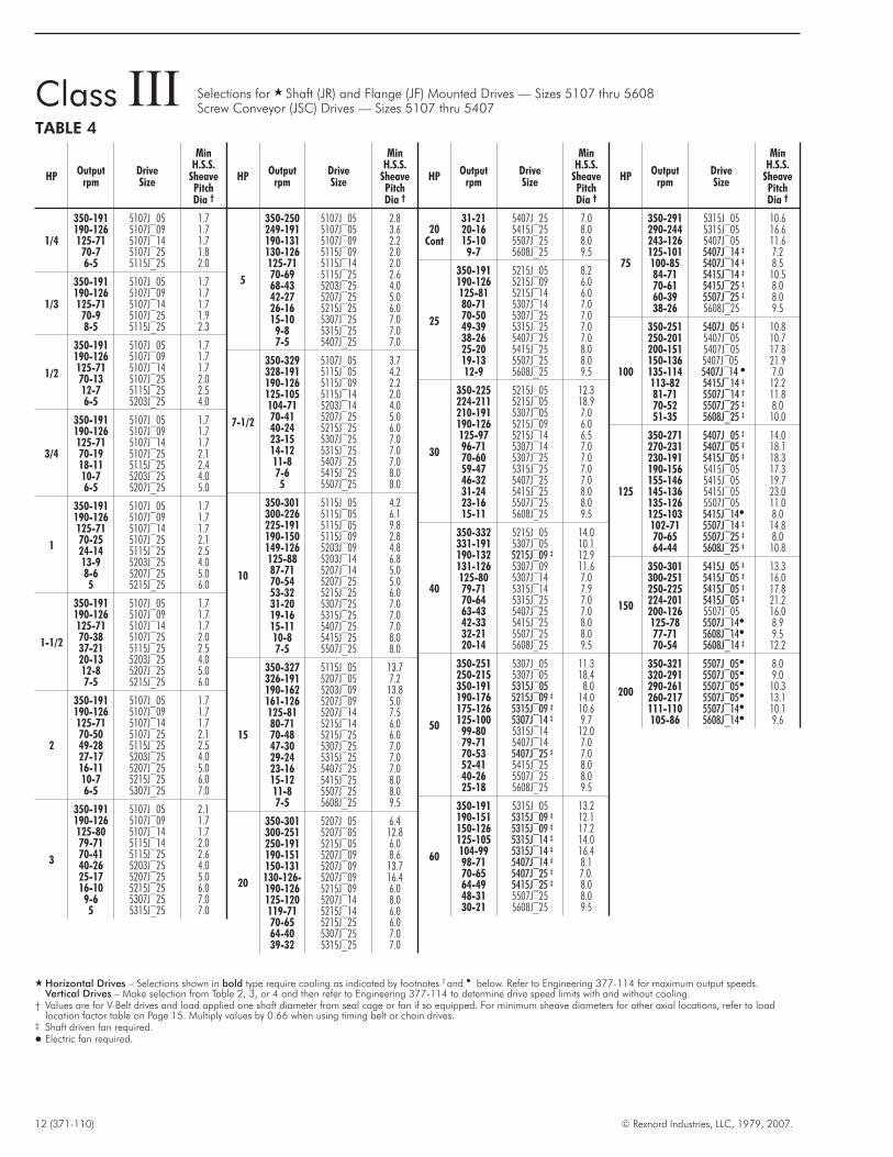
Class III Selections for � Shaft (JR) and Flange (JF) Mounted Drives — Sizes 5107 thru 5608Screw Conveyor (JSC) Drives — Sizes 5107 thru 5407
TABLE 4
HPOutput
rpmDriveSize
MinH.S.S.
SheavePitchDia †
1/4
350-191 5107J_05 1.7190-126 5107J_09 1.7125-71 5107J_14 1.770-7 5107J_25 1.86-5 5115J_25 2.0
1/3
350-191 5107J_05 1.7190-126 5107J_09 1.7125-71 5107J_14 1.770-9 5107J_25 1.98-5 5115J_25 2.3
1/2
350-191 5107J_05 1.7190-126 5107J_09 1.7125-71 5107J_14 1.770-13 5107J_25 2.012-7 5115J_25 2.56-5 5203J_25 4.0
3/4
350-191 5107J_05 1.7190-126 5107J_09 1.7125-71 5107J_14 1.770-19 5107J_25 2.118-11 5115J_25 2.410-7 5203J_25 4.06-5 5207J_25 5.0
1
350-191 5107J_05 1.7190-126 5107J_09 1.7125-71 5107J_14 1.770-25 5107J_25 2.124-14 5115J_25 2.513-9 5203J_25 4.08-6 5207J_25 5.05 5215J_25 6.0
1-1/2
350-191 5107J_05 1.7190-126 5107J_09 1.7125-71 5107J_14 1.770-38 5107J_25 2.037-21 5115J_25 2.520-13 5203J_25 4.012-8 5207J_25 5.07-5 5215J_25 6.0
2
350-191 5107J_05 1.7190-126 5107J_09 1.7125-71 5107J_14 1.770-50 5107J_25 2.149-28 5115J_25 2.527-17 5203J_25 4.016-11 5207J_25 5.010-7 5215J_25 6.06-5 5307J_25 7.0
3
350-191 5107J_05 2.1190-126 5107J_09 1.7125-80 5107J_14 1.779-71 5115J_14 2.070-41 5115J_25 2.640-26 5203J_25 4.025-17 5207J_25 5.016-10 5215J_25 6.09-6 5307J_25 7.05 5315J_25 7.0
HPOutput
rpmDriveSize
MinH.S.S.
SheavePitchDia †
5
350-250 5107J_05 2.8249-191 5107J_05 3.6190-131 5107J_09 2.2130-126 5115J_09 2.0125-71 5115J_14 2.070-69 5115J_25 2.668-43 5203J_25 4.042-27 5207J_25 5.026-16 5215J_25 6.015-10 5307J_25 7.09-8 5315J_25 7.07-5 5407J_25 7.0
7-1/2
350-329 5107J_05 3.7328-191 5115J_05 4.2190-126 5115J_09 2.2125-105 5115J_14 2.0104-71 5203J_14 4.070-41 5207J_25 5.040-24 5215J_25 6.023-15 5307J_25 7.014-12 5315J_25 7.011-8 5407J_25 7.07-6 5415J_25 8.05 5507J_25 8.0
10
350-301 5115J_05 4.2300-226 5115J_05 6.1225-191 5115J_05 9.8190-150 5115J_09 2.8149-126 5203J_09 4.8125-88 5203J_14 6.887-71 5207J_14 5.070-54 5207J_25 5.053-32 5215J_25 6.031-20 5307J_25 7.019-16 5315J_25 7.015-11 5407J_25 7.010-8 5415J_25 8.07-5 5507J_25 8.0
15
350-327 5115J_05 13.7326-191 5207J_05 7.2190-162 5203J_09 13.8161-126 5207J_09 5.0125-81 5207J_14 7.580-71 5215J_14 6.070-48 5215J_25 6.047-30 5307J_25 7.029-24 5315J_25 7.023-16 5407J_25 7.015-12 5415J_25 8.011-8 5507J_25 8.07-5 5608J_25 9.5
20
350-301 5207J_05 6.4300-251 5207J_05 12.8250-191 5215J_05 6.0190-151 5207J_09 8.6150-131 5207J_09 13.7130-126- 5207J_09 16.4190-126 5215J_09 6.0125-120 5207J_14 8.0119-71 5215J_14 6.070-65 5215J_25 6.064-40 5307J_25 7.039-32 5315J_25 7.0
HPOutput
rpmDriveSize
MinH.S.S.
SheavePitchDia †
20Cont
31-21 5407J_25 7.020-16 5415J_25 8.015-10 5507J_25 8.09-7 5608J_25 9.5
25
350-191 5215J_05 8.2190-126 5215J_09 6.0125-81 5215J_14 6.080-71 5307J_14 7.070-50 5307J_25 7.049-39 5315J_25 7.038-26 5407J_25 7.025-20 5415J_25 8.019-13 5507J_25 8.012-9 5608J_25 9.5
30
350-225 5215J_05 12.3224-211 5215J_05 18.9210-191 5307J_05 7.0190-126 5215J_09 6.0125-97 5215J_14 6.596-71 5307J_14 7.070-60 5307J_25 7.059-47 5315J_25 7.046-32 5407J_25 7.031-24 5415J_25 8.023-16 5507J_25 8.015-11 5608J_25 9.5
40
350-332 5215J_05 14.0331-191 5307J_05 10.1190-132 5215J_09 ‡ 12.9131-126 5307J_09 11.6125-80 5307J_14 7.079-71 5315J_14 7.970-64 5315J_25 7.063-43 5407J_25 7.042-33 5415J_25 8.032-21 5507J_25 8.020-14 5608J_25 9.5
50
350-251 5307J_05 11.3250-215 5307J_05 18.4350-191 5315J_05 8.0190-176 5215J_09 ‡ 14.0175-126 5315J_09 ‡ 10.6125-100 5307J_14 ‡ 9.799-80 5315J_14 12.079-71 5407J_14 7.070-53 5407J_25 ‡ 7.052-41 5415J_25 8.040-26 5507J_25 8.025-18 5608J_25 9.5
60
350-191 5315J_05 13.2190-151 5315J_09 ‡ 12.1150-126 5315J_09 ‡ 17.2125-105 5315J_14 ‡ 14.0104-99 5315J_14 ‡ 16.498-71 5407J_14 ‡ 8.170-65 5407J_25 ‡ 7.0.64-49 5415J_25 ‡ 8.048-31 5507J_25 8.030-21 5608J_25 9.5
HPOutput
rpmDriveSize
MinH.S.S.
SheavePitchDia †
75
350-291 5315J_05 10.6290-244 5315J_05 16.6243-126 5407J_05 11.6125-101 5407J_14 ‡ 7.2100-85 5407J_14 ‡ 8.584-71 5415J_14 ‡ 10.570-61 5415J_25 ‡ 8.060-39 5507J_25 ‡ 8.038-26 5608J_25 9.5
100
350-251 5407J_05 ‡ 10.8250-201 5407J_05 10.7200-151 5407J_05 17.8150-136 5407J_05 21.9135-114 5407J_14 � 7.0113-82 5415J_14 ‡ 12.281-71 5507J_14 ‡ 11.870-52 5507J_25 ‡ 8.051-35 5608J_25 ‡ 10.0
125
350-271 5407J_05 ‡ 14.0270-231 5407J_05 ‡ 18.1230-191 5415J_05 ‡ 18.3190-156 5415J_05 17.3155-146 5415J_05 19.7145-136 5415J_05 23.0135-126 5507J_05 11.0125-103 5415J_14� 8.0102-71 5507J_14 ‡ 14.870-65 5507J_25 ‡ 8.064-44 5608J_25 ‡ 10.8
150
350-301 5415J_05 ‡ 13.3300-251 5415J_05 ‡ 16.0250-225 5415J_05 ‡ 17.8224-201 5415J_05 ‡ 21.2200-126 5507J_05 16.0125-78 5507J_14� 8.977-71 5608J_14� 9.570-54 5608J_14 ‡ 12.2
200
350-321 5507J_05� 8.0320-291 5507J_05� 9.0290-261 5507J_05� 10.3260-217 5507J_05� 13.1111-110 5507J_14� 10.1105-86 5608J_14� 9.6
� Horizontal Drives – Selections shown in bold type require cooling as indicated by footnotes ‡ and � below. Refer to Engineering 377-114 for maximum output speeds.Vertical Drives – Make selection from Table 2, 3, or 4 and then refer to Engineering 377-114 to determine drive speed limits with and without cooling.
† Values are for V-Belt drives and load applied one shaft diameter from seal cage or fan if so equipped. For minimum sheave diameters for other axial locations, refer to loadlocation factor table on Page 15. Multiply values by 0.66 when using timing belt or chain drives.
‡ Shaft driven fan required.� Electric fan required.

Ratio Substitutions — The selection tables list the mosteconomical choice of drive size and ratio for a given output speedbased on 1750 and 1170 rpm motors. Where required, asubstitute gear ratio may be used in the selected drive sizeproviding it is double reduction and . . .
1. The ratio substitution is one of the following:
14:1 for 25:1 9:1‡ for 25:1 9:1‡ for 14:1
2. The hollow shaft speed for the substitute ratio does not exceedthe maximum rpm shown in the dimensions pages.
3. The resulting sheave ratio is practical.
4. The high speed sheave meets the minimum pitch diameterrequirements shown in Table 5.
‡ A 9:1 ratio substitution is available for Sizes 5107 thru 5307 only.
© Rexnord Industries, LLC, 1979, 2007. (371-110) 13
Engineering Data
TABLE 5 — Ratio SubstitutionsMinimum High Speed Shaft Sheave Pitch Diameter For Gear Drive Ratio Substitutions
DRIVESIZE
14:1 For 25:1 Ratio 9:1 For 25:1 Ratio 9:1 For 14:1 Ratio
Load Class & Motor HP MinSheavePitchDia �
MinSheavePitchDia �
MinSheavePitchDia �
Load Class & Motor HP MinSheavePitchDia �
MinSheavePitchDia �
MinSheavePitchDia �
Load Class & Motor HP MinSheavePitchDia �
MinSheavePitchDia �
MinSheavePitchDia �
I II III I II III I II III
5107 1/4-2 1/4-2 1/4-2 1.7 1.7 1.7 1/4-3 1/4-3 1/4-2 2.3 1.7 1.7 1/4-3 1/4-3 1/4-3 1.7 1.7 2.13 3 . . . 1.7 1.7 . . . . . . . . . 7 1/2 5 . . . 2.1 1.7
5115 1/2 - 3 1/4-3 1/4-3 2.0 2.0 2.0 1/2-3 1/3-2 1/4-2 2.0 2.6 2.6 5-7 1/2 5-7 1/2 3-7 1/2 2.2 2.6 2.65-7 1/2 5 5 2.0 2.0 2.0 5-7 1/2 3-5 3-5 2.7 2.6 2.7 10-15 10 . . . 2.8 2.6
5203 3/4-10 3/4-10 1/2-5 4.0 4.0 4.0 3/4-5 3/4-5 1/2-5 4.0 4.0 5.8 10 10 7 1/2 4.0 5.0 7.1. . . . . . . . . 7 1/2-10 7 1/2 - 10 . . . 6.3 6.6 15 . . . 10 11.8 16.6
5207 1 1/2-10 1-7 1/2 3/4-5 5.0 5.0 5.0 11/2- 10 1-7 1/2 3/4-5 6.1 6.2 6.3 15-20 15 10 7.0 5.2 5.015-20 10-15 7 1/2-10 5.4 5.0 5.0 15-20 10-15 7 1/2-10 10.8 9.6 9.4 25 20 . . . 16.1 14.6
5215 2-30 1 1/2-30 1-20 6.0 6.1 6.0 2-15 1 1/2-15 1-15 6.0 6.0 6.0 25-40 20-40 15-25 6.0 7.0 6.6. . . . . . . . . 20-30 20-30 20 6.0 6.4 7.8 50 50 30 9.6 11.3 7.7
5307 3-25 3-25 2-30 7.0 7.0 7.0 3-20 3-15 2-15 8.8 8.1 13.2 40 40 25 7.0 12.1 9.230-50 30-50 ---- 8.2 7.0 25-30 20-25 20 14.1 14.6 18.8 50 . . . 30 13.4 19.2
5315 5-50 5-30 3-25 8.8 7.0 7.060-75 40-60 30-40 12.3 11.9 9.6
5407 7 1/2-100 7 1/2-75 3-60 8.9 † 8.8 † 8.8 †
. . . . . . . . .
5415 10-40 7 1/2-40 7 1/2 -30 8.0 8.0 8.050-125 50-125 40-75 12.2 † 12.6 † 12.0 †
5507 15-75 15-75 7 1/2-60 8.0 8.0 8.0100-150 100-150 75-125 16.0 † 16.3 † 16.2 †
5608 20-100 15-100 15-75 9.5 9.5 9.5150-250 125-200 100-150 17.7 † 14.5 † 15.0 †
� Values are for V-belt drives with load applied one shaft diameter from seal cage. For minimum sheave diameters for other axial locations, refer to load location factor table onpage 15. Multiply values by 0.66 when using timing belt or chain drives.
† Load applied one shaft diameter from Fan Hub.
TABLE 6 — 1964 (Type T) NEMA Motor Standards †
MOTOR SPEED AND FRAME SIZE MOTOR SHAFT DIMENSIONS – INCHES
Motorhp
1800rpm
1200rpm
900rpm
Motorhp
1800rpm
1200rpm
900rpm
Motorhp
1800rpm
1200rpm
900rpm
MotorFrame
D U VKey(Sq)
MotorFrame
D U VKey(Sq)
MotorFrame
D U VKey(Sq)
½ 56 56 143 7 ½ 213 254 256 50 326 365 404 56 3 ½ 5/8 2 3/16 215 5 ¼ 1 3/8 3 1/8 5/16 326 8 2 1/8 5 ½¾ 56 143 145 10 215 256 284 60 364 404 405 143 3 ½ 7/8 2 3/16 254 6 ¼ 1 5/8 3 ¾ 3/8 364 9 2 3/8 5 5/8 5/8
1 143 145 182 15 254 284 286 75 365 405 . . . 145 3 ½ 7/8 2 3/16 256 6 ¼ 1 5/8 3 ¾ 3/8 365 9 2 3/8 5 5/8 5/8
1 ½ 145 182 184 20 256 286 324 100 404 . . . . . . 182 4 ½ 1 1/8 2 ½ ¼ 284 7 1 7/8 3/8 ½ 404 10 2 7/8 7 ¾2 145 184 213 25 284 324 326 125 405 . . . . . . 184 4 ½ 1 1/8 2 ½ ¼ 286 7 1 7/8 3/8 ½ 405 10 2 7/8 7 ¾3 182 213 215 30 286 326 364 150 444 . . . . . . 213 5 ¼ 1 3/8 3 1/8 5/16 324 8 1/8 5 ½ 444 11 3 3/8 8 ¼ 7/8
5 184 215 254 40 324 364 365 200 445 . . . . . . . . . . . . . . . . . . . . . . . . . . . . . . . . . . . . 445 11 3 3/8 8 ¼ 7/8
† Frame numbers listed are for 110, 208, 220/440 and 550 volts. Falk Motor Mounts are pre-drilled for rerated 1964 NEMA standard foot-mounted motors.
VKEY
U D
Motor Ratings andDimensions are inaccordance withNEMA standards

Overhung Load at Hollow Shaft †
OVERHUNG LOADS — Overhung load is imposed upon a shaftwhen a pinion, sprocket or sheave is used as a power take-off.The magnitude of the load varies with the type of take-off and itsproximity to the shaft bearing. Calculate the load (includingminimum required service factor) and check the result against thetabulated overhung load rating. The overhung load formula belowconsiders the transmitted horsepower without service factor. This isappropriate for applications where starting loads, momentaryoverloads and brake capacities do not exceed 200% of driverating (100% overload). For other conditions, compute theequivalent power by multiplying the transmitted power by theappropriate service factor.
Overhung Load =126,000 x hp x F x L
Pitch Dia xC f
rpm
Fc = Load Connection Factor
Sprocket � 1.00
Synchronous (timing) Belts . . . . . . . . . . . . . . . . . . . . . . . . . 1.30
V-Belt. . . . . . . . . . . . . . . . . . . . . . . . . . . . . . . . . . . . . . . . 1.50
Machined Pinion & Gear � . . . . . . . . . . . . . . . . . . . . . . . . 1.25
Flat Belt . . . . . . . . . . . . . . . . . . . . . . . . . . . . . . . . . . . . . . 2.50� Refer all multiple chain sprocket and pinion mounted applications to Falk for
deflection analysis.
Lf = Load Location Factor
Select Lf from Table 7, under drive size and opposite distancefrom end of hollow shaft.
Locate the center line of the load as close to the drive sealcage as practical to minimize the effect of the overhung load andincrease bearing life.
Consult Factory for Higher Overhung Load Ratings — Inmany cases, overhung load capacity in excess of that published isavailable. If the actual load should exceed the published capacity,refer full details to Falk; provide complete application information(see Page 7), as well as direction of rotation, location anddirection of applied load.
EXAMPLE — A chain drive requiring 10 hp is being driven by a5207JF14, 100 rpm output, using a single-width, 21-tooth, 8.4"pitch diameter sprocket mounted on a low speed stub shaft.Center line of the load is 4" from the output face of the housing.
PROCEDURE: Fc = 1.00 Lf = 1.08
Overhung Load =126,000 x 10 x 1.00 x 1.08
8.4 x 1001620 lb=
Since the overhung load capacity shown for a 5207JF14 drive at100 rpm is 2730 pounds, the application is satisfactory.
Driven Shaft Diameter TolerancesShaft diameters shall be within commercial tolerances for turnedand polished round bars as shown below.
Keys and keyways in the supporting shaft shall be in accordancewith ANSI B17.1 for size, depth, offset, lead, and parallelism.
14 (371-110) © Rexnord Industries, LLC, 1979, 2007.
Engineering DataTABLE 7 — Load Location Factor (Lf) For Load
Located at Dimension “X” Below
DistanceD �
Inches
DRIVE SIZE
5107 5115 5203 5207 5215 5307 5315 5407 5415 5507 5608
20.93 0.86 0.84 0.83 0.80 0.76 0.76
3 1.13 0.99 0.96 0.94 0.89 0.85 0.84 0.724 1.37 1.19 1.14 1.08 0.99 0.94 0.92 0.79 0.77 0.74 0.725 1.62 1.40 1.33 1.26 1.14 1.04 1.00 0.86 0.83 0.80 0.776 . . . I .60 1.53 1.44 1.29 1.18 1.13 0.94 0.89 0.85 0.82
7 . . . . . . . . . 1.62 1.45 1.32 1.27 1.02 0.95 0.91 0.878 . . . . . . . . . . . . . . . 1.46 1.40 1.14 1.02 0.97 0.92
10 . . . . . . . . . . . . . . . . . . 1.67 1.38 1.23 1.14 1.0212 . . . . . . . . . . . . . . . . . . 1.94 1.62 1.43 1.33 1.1916 . . . . . . . . . . . . . . . . . . . . . . . . 1.85 1.71 1.53
� Distance “D” is in inches from the output face of the housing. Interpolate for Lf
factors at intermediate distances. For example, Lf is 1.11 for Size 5307 whendistance is 5.50 inches. Refer to Factory for distances greater than those shown.
† NOTE: For JF Flanged Mounted Drives, the TA Taper bushing, using the spannernut, is not intended to provide the full external load capacities given in Tables 8 &9. Use the tapered driven shafts manufactured per Manual 377-140, ornon-tapered driven shafts and bushings per Manual 377-142 (5107-5315JF) &377-144 (5407-5608JF), or refer your application to Factory for review.
TABLE 8 — Guide To Low Speed ShaftOverhung Load Capacity – lb ‡
Consult Factory For Higher Overhung Load Ratings
DRIVESIZE
Ratios 9:1, 14:1 or 25:1 Ratio 5:1
Output Speed – rpm Output Speed – rpm
10 25 50 75 100 125 150 175 90 200 300 350
Overhung Load At Dimension “X” Below
5107 3660 2720 2150 1870 1700 1600 1520 1460 1900 1490 1310 12505115 4370 3240 2540 2200 1990 1850 1750 1670 2200 1720 1520 14505203 4170 3010 2360 2050 1860 1740 1630 1516 2020 1580 1390 13305207 6240 4440 3450 3000 2730 2540 2400 2280 3120 2430 2150 2050
5215 9530 6950 5420 4710 4310 4050 3860 3700 4770 3730 3300 31405307 8860 6300 4810 4090 3730 3470 3270 3110 4460 3470 3060 29105315 10000 8700 6630 5740 5260 4040 3757 3494 6190 4850 4280 40905407 9500 9120 6940 5940 5370 4960 . . . . . . 6010 4620 4090 3910
5415 15000 13210 10080 8610 7750 7160 . . . . . . 9190 7200 6370 60705507 Refer to Factory . . . . . . . . . . . . . . . . . .5608 Refer to Factory . . . . . . . . . . . . . . . . . .
‡ Published values of low speed shaft overhung load are for loads applied one shaftdiameter from the seal cage with a service factor of unity. Where overhung load isproportional to torque (i.e. pinion, sprocket, or sheave applications) an appropriateservice factor should be considered in the overhung load calculation.
D D
X X
CENTEROF
OVERHUNGLOAD
CENTEROF
OVERHUNGLOAD
Sizes 5107 thru 5315JF Sizes 5407 thru 5608JF
Shaft DiameterMaximum UndersizeVariation – Inches
to 1.50 0.004over 1.50 to 2.50 incl. 0.005over 2.50 to 4 incl. 0.006over 4 to 6 incl. 0.007over 6 to 8 incl. 0.008

TABLE 10 — Values shown in Table 10 above are referred to thedrive high speed shaft. The WR2 referred to the hollow (low speed)shaft equals the exact total ratio squared times the H.S. shaft WR2.Refer to Factory for values of unlisted ratios and drive sizes.
TABLE 11 — Minimum sheave diameters listed in Tables 2, 3 & 4are for V-belt drives with the load applied one shaft diameter fromthe seal cage or from the fan guard, if equipped with a shaftcooling fan. For minimum sheave diameters for loads applied at agreater distance, multiply the published minimum sheave diameterby the load location factor (from Table 11) for the “distance”required. When using chains or timing belts, multiply minimumsheave diameters by 0.66.
Thrust at Hollow ShaftThe capacities in Table 9 are for PURE thrust loads for eitherdirection of shaft rotation. Higher values are listed in Manual377-115 for specific shaft rotations. When both radial and thrustloads are involved, refer application details to the Factory.
© Rexnord Industries, LLC, 1979, 2007. (371-110) 15
Engineering Data
A B A B
TABLE 9 — Guide To Pure Thrust Capacity At Hollow Shaft – lb
JF & JFVDRIVESIZE
Ratios 9:1, 14:1 or 25:1 Ratio 5:1JF & JFVDRIVESIZE
Ratios 9:1, 14:1 or 25:1 Ratio 5:1
Output Speed – rpm Output Speed – rpm Output Speed – rpm Output Speed – rpm
10 25 50 75 100 125 150 175 90 200 300 350 10 25 50 75 100 125 150 175 90 200 300 350
Thrust: A towards B Thrust: B towards A
5107 3590 2840 2150 1820 1620 1540 1470 1420 2060 1610 1410 1350 5107 3490 2840 2160 1820 1620 1540 1470 1420 2060 1610 1410 13505115 4390 4390 4350 3680 3250 3020 2860 2730 3920 3060 2700 2570 5115 3490 3490 3490 3490 3270 3040 2870 2740 3490 3070 2700 25805203 6680 5680 4310 3670 3290 3060 2850 2720 3800 2940 2580 2460 5203 5590 5590 4410 3760 3380 3150 2940 2800 3880 3000 2640 25105207 8120 7750 5760 4930 4450 4120 3860 3640 5600 4340 3830 3660 5207 5590 5590 5590 5100 4610 4240 4000 3780 5590 4440 3920 3740
5215 10180 10180 9900 8440 7690 7270 6960 6720 9130 7120 6260 5980 5215 8170 8170 8170 8170 7900 7460 7140 6890 8170 7250 6380 60905307 13160 11010 8240 6750 6100 5640 5300 5010 8440 6500 5690 5410 5307 10770 10770 8640 7080 6410 5940 5570 5270 8660 6680 5850 55605315 13220 8470 6070 5050 4660 4370 4064 3780 5910 4660 4100 3420 5315 13680 8640 6230 5260 4830 4530 4213 3918 6060 4780 4280 40205407 13000 9810 6320 5520 4890 4370 . . . . . . 6230 4830 4270 4070 5407 12210 9890 6900 5600 4960 4440 . . . . . . 6290 4730 4190 4010
5415 16400 16400 14730 12100 10630 9630 . . . . . . 14590 11400 10070 9590 5415 18980 18980 14730 12100 10630 9680 . . . . . . 14590 11200 9990 95305507 6000 6000 6000 6000 6000 6000 . . . . . . . . . . . . . . . . . . 5507 20580 20580 15230 13190 12160 11420 . . . . . . . . . . . . . . . . . .5608 14800 14800 14800 14300 13425 12554 . . . . . . . . . . . . . . . . . . 5608 29000 23580 15810 13990 13122 12271 . . . . . . . . . . . . . . . . . .
TABLE 10 — WR2 (lb-in2) Referred to H.S. Shaft
DRIVESIZE
Ratio DRIVESIZE5:1 9:1 14:1 25:1
5107 1.37 1.28 0.83 0.43 51075115 3.45 3.14 2.08 1.07 51155203 7.03 5.94 3.59 2.00 52035207 15.01 12.86 8.34 4.70 5207
5215 39.02 35.69 19.57 10.92 52155307 70.67 63.63 34.96 20.82 53075315 82.89 72.42 47.18 28.62 53155407 171.83 . . . 74.86 41.94 5407
5415 275.77 . . . 140.58 74.51 54155507 . . . . . . 262.79 137.81 55075608 . . . . . . 457.90 232.40 5608
TABLE 11 — H.S. Shaft Load Location Factors
DistanceD in
Inches †
DRIVE SIZE
5107 5115 5203 5207 5215 5307 5315 5407 5415 5507 5608
.500 0.94.750 0.98 0.95.875 1.00 0.97
1.000 1.05 0.98 0.95
1.125 1.11 1.00 0.96 0.951.250 1.16 1.05 0.98 0.971.375 1.21 1.09 1.00 0.98 0.951.500 1.27 1.14 1.04 1.00 0.96 0.94 0.93
1.750 1.37 1.24 1.11 1.07 0.99 0.96 0.95 0.93 0.941.875 1.43 1.28 1.15 1.10 1.00 0.98 0.96 0.94 0.952.000 1.48 1.33 1.19 1.14 1.03 0.99 0.98 0.96 0.96 0.95 0.942.125 . . . 1.38 1.23 1.17 1.06 1.00 0.99 0.97 0.97 0.96 0.94
2.250 . . . 1.43 1.26 1.20 1.09 1.03 1.00 0.98 0.98 0.96 0.952.500 . . . 1.52 1.34 1.27 1.15 1.08 1.05 1.00 1.00 0.98 0.972.750 . . . . . . 1.41 1.34 1.21 1.13 1.10 1.05 1.05 1.00 0.983.000 . . . . . . 1.49 1.41 1.27 1.19 1.15 1.11 1.10 1.05 1.00
3.250 . . . . . . . . . 1.47 1.33 1.24 1.20 1.16 1.14 1.09 1.043.500 . . . . . . . . . 1.54 1.39 1.30 1.25 1.21 1.19 1.14 1.093.750 . . . . . . . . . . . . 1.45 1.35 1.30 1.26 1.24 1.18 1.134.000 . . . . . . . . . . . . 1.51 1.40 1.35 1.32 1.29 1.23 1.17
4.250 . . . . . . . . . . . . . . . 1.46 1.40 1.37 1.34 1.27 1.214.500 . . . . . . . . . . . . . . . 1.51 1.45 1.42 1.38 1.32 1.264.750 . . . . . . . . . . . . . . . . . . 1.50 1.48 1.43 1.37 1.305.000 . . . . . . . . . . . . . . . . . . 1.55 1.53 1.48 1.41 1.34
5.250 . . . . . . . . . . . . . . . . . . . . . 1.58 1.53 1.46 1.395.500 . . . . . . . . . . . . . . . . . . . . . 1.63 1.58 1.50 1.435.750 . . . . . . . . . . . . . . . . . . . . . 1.69 1.62 1.55 1.476.000 . . . . . . . . . . . . . . . . . . . . . 1.74 1.67 1.60 1.51
6.250 . . . . . . . . . . . . . . . . . . . . . . . . 1.72 1.64 1.566.500 . . . . . . . . . . . . . . . . . . . . . . . . . . . 1.69 1.606.750 . . . . . . . . . . . . . . . . . . . . . . . . . . . 1.73 1.647.000 . . . . . . . . . . . . . . . . . . . . . . . . . . . 1.78 1.69
7.250 . . . . . . . . . . . . . . . . . . . . . . . . . . . 1.82 1.737.500 . . . . . . . . . . . . . . . . . . . . . . . . . . . 1.87 1.777.750 . . . . . . . . . . . . . . . . . . . . . . . . . . . . . . 1.818.000 . . . . . . . . . . . . . . . . . . . . . . . . . . . . . . 1.868.250 . . . . . . . . . . . . . . . . . . . . . . . . . . . . . . 1.90
† Distance “D” is in inches from the input face of the H.S. seal cage. Interpolate forload location factors at intermediate distances. For example, the load locationfactor is 1.27 for Size 5307 when distance is 3.375 inches. Refer to Factory fordistances greater than those shown.
Sizes 5407 thru 5608JFSizes 5107 thru 5315JF

16 (371-110) © Rexnord Industries, LLC, 1979, 2007.
Size 5107/Dimensions – InchesShaft Mounted (JR) & Flange Mounted (JF) Drive �
BASICDRIVESIZE †
PartNumber
ExactRatio
MaxOutput
rpm
Wtlb
5107J05A 0793781 5.077 350 255107J09A 0793782 9.462 190 305107J14A 0793783 14.43 125 305107J25A 0793784 25.81 70 30
� MIN = Minimum required projection of drivenshaft.MAX = Maximum projection of driven shaft whichallows for use of thrust plate.
† JR = Basic Drive + Bushing + Torque ArmJF = Basic Drive (Bushing Optional)JSC = Basic Drive + Seal Housing + Drive Shaft
Hollow Shaft Details
See Manual 377-140 for JF drive tapereddriven shaft recommendations. See Manual377-142 for JF drives using tapered bushings.
30 UP°
5 DOWN°
10MAX.
°5°MAX.0° INCLINE DOWN ON DRIVES
WITH BACKSTOPS IN 9 OR 12O'CLOCK MOUNTING.
INCLINE ROTATION
Angular Limits For Horizontal Mounting
(All Clock Positions)Refer to Factory for lubrication analysis of all inclined drivesexceeding the maximum specified below. Also for drives withcombined incline down and rotation.
3–HOLES1/2 – 13 UNC x 1.00–TAP
2.330
.560
1.46 RADIUS
INPUT END COVER &BACKSTOP LOCATION
.560
MOUNTINGSURFACE
2.562
5.124
10.43
8.40 2.03
1.85 5.925.00 MIN7.19 MAX
1.26
3.31
REMOVABLESHAFT COVER
INPUT SHAFT KEY3/16 x 3/16 x 1-3/4
.8750 +.0000-.0005
2.00
DRAIN
4.80
.25
1.00
1.25TORQUE ARMMAX. REACTION: 2090 LBS.
2 – HOLES FOR 3/8 DIA.SAE GRADE 5 BOLTS
VENT &FILLER PLUG
9.16
4.58
4.11OILLEVEL
10.37
7.24
2.90 1.16
5/8 DIA.
2.50
3.56
ALTERNATEPOSITION
8.5 STD4.1 MIN21 MIN27 MAX
SETSCREW
30 MAXº
2º
.125 DEEP
2.874 DIA. REGISTER+.002– .000
2º
30 MAXº
TA Taper Bushings
Accessories
2.50 1.89
SET SCREWNUT
RETAININGRING
TAPEREDBUSHING
DRIVENSHAFT
HOLLOW SHAFTKEY (FURNISHED)
5.00
Style No. 1 — Thin-wall bushing
SET SCREW
NUT
RETAININGRING
TAPEREDBUSHING
HOLLOW SHAFTKEY (FURNISHED)
DRIVEN SHAFTSQUARE KEY(NOT FURNISHED)
Style No. 2 — Thick-wall bushing
BUSHINGSIZE
PartNumber ‡
StyleNo.
DrivenShaft
Keyway/MinKey Length �
Wtlb
BU5107J-1.000 0769061 2 ¼ x 1/8 x 2½ 2.1BU5107J-1.125 0769062 2 ¼ x 1/8 x 2¼ 1.8BU5107J-1.188 0769063 2 ¼ x 1/8 x 2 1.6BU5107J-1.250 0769064 1 ¼ x 1/8 x 2½ 1.5BU5107J-1.375 6720659 1 3/8 x 3/16 x 2½ 1.0BU5107J-1.438 0769065 1 3/8 x 3/16 x 2½ 1.0
‡ Consists of bushing, drive key, nut, retaining ring andsetscrew.
� Check strength of driven shaft and unfurnished key.
Torque Arm
TA5107JPN 0785261Wt. 4 lb.
Thrust Plate Kit
TP5107JPN 0769060Wt. 1 lb.
Vertical Breather
VB5107J-HSS UpPN 0738540VB5107J-HSS DownPN 0738553Wt. 6 lb.
COMBINATIONDIPSTICK & VENT
19.203.50
DRAIN
OILLEVEL
DRAIN
9.00
VENTEDFILLER PLUG
3.50
INPUT SHAFT DOWN INPUT SHAFT UP
Vertical Drives
Refer to Factory for lubrication analysis ofall vertical drives exceeding ±1° fromtrue vertical.
Backstop
BS5107J05/09/14PN 0795654BS5107J25PN 0795655Wt. 1 lb.

© Rexnord Industries, LLC, 1979, 2007. (371-110) 17
Size 5107/Dimensions – InchesScrew Conveyor (JSC) Drive �
BASICDRIVESIZE
�
Screw Conveyor Components
O DB EB FB � LB MB NB OB PB QB UB †CplgDia
ScrewDia
Max Tqlb-in
Drive Shaftw/Thrust Plate ‡
PartNo.
TroughSpacer
Wtlb
SealHousing
PartNo.
Wtlb
5107
1.500 6, 9 3,900 DS5107J-1.500 6720046 . . . 8 SH5107J 0769058 15 12.60 4.000 2.000 .500 .875 1.250 .875 3.000 .531 9.000 1.5002.000 9, 12 3,900 DS5107J-2.000 6720047 . . . 10 SH5107J 0769058 15 12.60 5.125 2.562 .625 .875 1.250 .875 3.000 .656 9.000 2.0002.437 12, 14 3,900 DS5107J-2.437 6720048 0752578 14 SH5107J 0769058 15 12.86 5.625 2.812 .625 .938 1.812 .938 3.000 .656 9.688 2.4373.000 12-20 3,900 DS5107J-3.000 6720049 0752578 18 SH5107J 0769058 15 12.86 6.000 3.000 .750 1.000 1.875 1.000 3.000 .781 9.875 3.000
� Dimensions are for reference only and are subject to change without notice unless certified.� Hexagon head screws with UNC thread are furnished by Falk for mounting the gear drive to the trough end.
† Shaft diameters under 3” are held to limits of +.000”, –.002”. Shaft diameters 3” and over are held to limits of +.000”, –.003”.‡ See Page 41 for optional 316 stainless steel drive shafts – stocked.
DB
EB
DBEB
4 TAPPED HOLES & 4 THRU SLOTS FORDIA TROUGH END FASTENERSFB
– ––
SEAL HOUSING
VENT & FILLER PLUG
QB O
TROUGHEND
2.03MB
NB
LBCOUPLING
SHAFT UB–
3– °
–
HOLES AT 90IN DRIVE SHAFT
DIA.PB
DRAIN
2.00
REMOVABLESHAFT COVER
INPUT SHAFT KEY3/16 x 3/16 x 1-3/4
.8750 +.0000-.0005
3 6 9 12
Drive Mounting Positions
(Based on clock position of input shaft relative tohollow shaft.)
Trough End Seals
Motor Mounts
Waste Packing
Std.-Includedwith seal housingPN 0925058Wt. 1 lb.
Lip Seal
PN 2905318Wt. 1 lb.
Packing Gland Seal Kit
PGSK5107JPN 0769059Wt. 1 lb.
Packing Gland Seal (Only)
PG5107JPN 2109907Wt. 1 lb.
Frame 56 143-145T 182-184T 213-215T
D 3.50 3.50 4.50 5.25
E 2.50 2.00 2.50 3.25
ShaftCenters
Min-Max Min-Max Min-Max Min-Max
(S) Short . . . . . . . . . . . .
(M) Medium 20.9-24.2 20.9-24.2 21.9-25.1 22.6-25.9
(L) Long 24.1-27.4 24.1-27.4 25.1-28.4 25.8-29.1
MOTORMOUNTSIZE �
PartNumber
Type T Frame � K U MotorMountWt-lbMin Max Min Max Med Long
MM5107J-1 0738714 56 215 0.64 3.92 10.56 13.76 40� Dimensions are for reference only and are subject to change without notice unless certified. When determining belt length for minimum shaft centers, follow the belt
manufacturer’s installation allowance recommendations.� Refer to Manual 377-820 for standard vertical assemblies and all Type U frame motor limits.� Refer to Factory for alternate horizontal drive assemblies (high speed shaft over low speed).
Standard Horizontal Drive Assembly – (6 o’clock) � (3-9-12 o’clock optional)
ADJUSTING SCREWSFOR BELT
TENSIONING
15.00
MOTORMOUNT
1.26
4.403.80
8.84
4.40
4-HOLES PER SUPPORTFOR .375 DIA. BELT GUARDFASTENERS
8.94
7.10
4.94 UTYPE JSC:TO SEALHOUSING FACE
TYPE JR:TO FACEOF NUT
TYPE JF:TO MOUNTINGFACE
13.80
K
D
11.30
K
DM
S
SHAFTCENTERS
D
K
17.00
LSHAFT
CENTERS
E
3 2 1
OB OB
QB

18 (371-110) © Rexnord Industries, LLC, 1979, 2007.
Size 5115/Dimension –InchesShaft Mounted (JR) & Flange Mounted (JF) Drive �
TA Taper Bushings
2.75 2.10
SET SCREW
NUT
RETAININGRING
TAPEREDBUSHING
DRIVENSHAFT
HOLLOW SHAFTKEY (FURNISHED)
5.55
Style No. 1 — Thin-wall bushing
SET SCREW
NUT
RETAININGRING
TAPEREDBUSHING
HOLLOW SHAFTKEY (FURNISHED)
DRIVEN SHAFTSQUARE KEY(NOT FURNISHED)
Style No. 2 — Thick-wall bushing
BUSHINGSIZE
PartNumber ‡
StyleNo.
DrivenShaft
Keyway/MinKey Length �
Wtlb
BU5115J-1.188 0769077 2 ¼ x 1/8 x 4¼ 4.3BU5115J-1.250 0769078 2 ¼ x 1/8 x 4 4.1BU5115J-1.438 0769079 2 3/8 x 3/16 x 2¼ 3.5BU5115J-1.500 0769080 2 3/8 x 3/16 x 2¼ 3.3
BU5115J-1.625 0769081 1 3/8 x 3/16 x 2¾ 2.9BU5115J-1.688 0769082 1 3/8 x 3/ 16x 2¾ 2.7BU5115J-1.750 0769083 1 3/8 x 3/16 x 2¾ 2.4BU5115J-1.938 0769084 1 ½ x ¼ x 2¾ 1.7
‡ � (See footnotes on Page 16.)
BASICDRIVESIZE †
PartNumber
ExactRatio
MaxOutput
rpm
Wtlb
5115J05A 0793858 5.053 350 405115J09A 0793859 9.357 190 455115J14A 0793860 13.95 125 455115J25A 0793861 24.87 70 45
� † (See footnotes on Page 16.)
Hollow Shaft Details
See Manual 377-140 for JF drive tapered drivenshaft recommendations. See Manual 377-142 forJF drives using tapered bushings.
30 UP°
5 DOWN°
10MAX.
°5°MAX.0° INCLINE DOWN ON DRIVES
WITH BACKSTOPS IN 9 OR 12O'CLOCK MOUNTING.
INCLINE ROTATION
Angular Limits For Horizontal Mounting
(All Clock Positions)
Refer to Factory for lubrication analysis of all inclineddrives exceeding the maximum specified below. Also fordrives with combined incline down and rotation.
3–HOLES5/8 – 11 UNC x 1.17–TAP
2.812
.562
1.88 RADIUS
INPUT END COVER &BACKSTOP LOCATION
.562
MOUNTINGSURFACE
2.844
5.688
3.622 DIA. REGISTER+.002– .001
11.83
9.32 2.51
2.08 6.605.55 MIN8.05 MAX
1.46
4.06
REMOVABLESHAFT COVER
INPUT SHAFT KEY1/4 x 1/4 x 2-1/4
1.1250+.0000–.0005
2.50
DRAIN
5.38
.25
1.00
1.25TORQUE ARMMAX. REACTION: 3490 LBS.
2 – HOLES FOR 3/8 DIA.SAE GRADE 5 BOLTS
VENT &FILLER PLUG
10.36
5.18
4.61
OILLEVEL
11.86
8.23
3.49 1.38
5/8 DIA.
2.50
3.56
ALTERNATEPOSITION
8.5 STD4.1 MIN21 MIN27 MAX
SETSCREW
2º
30 MAXº
.125 DEEP
2º
30 MAXº
Accessories
Torque Arm
TA5115JPN 0785261Wt. 4 lb.
Backstop
BS5115J05/09/14PN 0793995BS5115J25PN 0795658Wt. 1 lb.
Thrust Plate Kit
TP5115JPN 0769076Wt. 1 lb.
Vertical Breather
VB5115J-HSS UpPN 0738540VB5115J-HSS DownPN 0738563Wt. 6 lb.
COMBINATIONDIPSTICK & VENT
18.304.00
DRAIN
OILLEVEL
DRAIN
9.30
VENTEDFILLER PLUG
4.00
INPUT SHAFT DOWN INPUT SHAFT UP
Vertical Drives
Refer to Factory for lubrication analysis ofall vertical drives exceeding ±1° fromtrue vertical.

© Rexnord Industries, LLC, 1979, 2007. (371-110) 19
Size 5115/Dimensions – InchesScrew Conveyor (JSC) Drive �
BASICDRIVESIZE
�
Screw Conveyor Components
DB EB FB � LB MB NB OB PB QB UB †CplgDia
ScrewDia
Max Tqlb-in
Drive Shaftw/Thrust Plate ‡
PartNo.
Wtlb
SealHousing
PartNo.
Wtlb
5115
1.500 6, 9 5,200 DS5115J-1.500 � 6720050 14 SH5115J 0769074 14 4.000 2.000 .500 3.875 1.250 .875 3.000 .531 9.000 � 1.5002.000 9, 12 6,800 DS5115J-2.000 � 6720051 14 SH5115J 0769074 14 5.125 2.562 .625 .875 1.250 .875 3.000 .656 9.000 2.0002.437 12, 14 8,050 DS5115J-2.437 6720052 18 SH5115J 0769074 14 5.625 2.812 .625 .938 1.812 .938 3.000 .656 9.688 2.4373.000 12-20 8,050 DS5115J-3.000 6720053 23 SH5115J 0769074 14 6.000 3.000 .750 1.000 1.875 1.000 3.000 .781 9.875 3.000
� � † ‡ (See footnotes on Page 17.)� Check drive shaft torque & bending capacity and coupling bolt shear & bearing stresses against load to be transmitted. See above drawing for location of third drive
shaft-coupling bolt hole if required.
DB
EB
DBEB
4 TAPPED HOLES & 4 THRU SLOTS FORDIA TROUGH END FASTENERSFB
– ––
SEAL HOUSING
VENT & FILLER PLUG
QB 13.76
TROUGHEND
2.51MB
NB
LBCOUPLING
SHAFT UB–
3 HOLES AT 90IN DRIVE SHAFT
DIA.PB
– °
–
DRAIN
2.50
REMOVABLESHAFT COVER
INPUT SHAFT KEY1/4 x 1/4 x 2-1/4
1.1250+.0000-.0005
3 6 9 12
Drive Mounting Positions
(Based on clock position of input shaft relativeto hollow shaft.)
Trough End Seals
Motor Mounts
Waste Packing
Std.-Includedwith seal housingPN 0925058Wt. 1 lb.
Lip Seal
PN 0912859Wt. 1 lb.
Packing Gland Seal Kit
PGSK5115JPN 0769075Wt. 1 lb.
Packing Gland Seal (Only)
PG5115JPN 1184314Wt. 1 lb.
Frame 56 143-145T 182-184T 213-215T
D 3.50 3.50 4.50 5.25
E 2.50 2.00 2.50 3.25
ShaftCenters
Min-Max Min-Max Min-Max Min-Max
(S) Short . . . . . . . . . . . .
(M)Medium 21.2-24.5 21.2-24.5 22.2-25.5 23.0-26.4
(L) Long 24.4-27.7 24.4-27.7 25.4-28.7 26.2-29.5
Frame 254-256T
D 6.25
E 4.00
ShaftCenters
Min-Max
(S) Short . . .
(M)Medium 24.6-28.3
(L) Long 27.8-31.5�
� At 6 o’clock only.
MOTORMOUNTSIZE �
PartNumber
Type T Frame �
F H JK
LU Motor
MountWt-lbMin Max Min Max Short Med Long
MM5115J-1 0738715 56 215 8.30 4.30 6.20 0.64 3.92 15.00 . . . 10.72 13.92 42MM5115J-2 0786773 254 256 13.80 9.80 11.70 1.26 4.98 20.50 . . . 10.72 13.92 82� � � (See footnotes on Page 17.)
Standard Horizontal Drive Assembly – (6 o’clock) � (3-9-12 o’clock optional)
3 2 1
OB OB
QB
ADJUSTING SCREWSFOR BELT
TENSIONING
E
MOTORMOUNT
1.26
4.404.10
8.84
4.40
4-HOLES PER SUPPORTFOR .375 DIA. BELT GUARDFASTENERS
UTYPE JSC:TO SEALHOUSING FACE
TYPE JR:TO FACEOF NUT
TYPE JF:TO MOUNTINGFACE
13.56
K
DM
S
SHAFTCENTERS
D
K
16.76
LSHAFT
CENTERS
K
DL
H
J
F
8.75
6.31
–2 –1Assy Assy
20 (371-110) © Rexnord Industries, LLC, 1979, 2007.
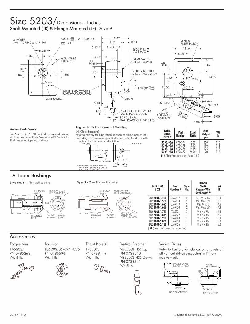
Size 5203/Dimensions – InchesShaft Mounted (JR) & Flange Mounted (JF) Drive �
TA Taper Bushings
3.25 1.56
SET SCREWNUT
RETAININGRING
TAPEREDBUSHING
DRIVENSHAFT
HOLLOW SHAFTKEY (FURNISHED)
5.53
Style No. 1 — Thin-wall bushing
SET SCREW
NUT
RETAININGRING
TAPEREDBUSHING
HOLLOW SHAFTKEY (FURNISHED)
DRIVEN SHAFTSQUARE KEY(NOT FURNISHED)
Style No. 2 — Thick-wall bushing
BUSHINGSIZE
PartNumber ‡
StyleNo.
DrivenShaft
Keyway/MinKey Length �
Wtlb
BU5203J-1.438 0769117 2 3/8 x 3/16 x 3¼ 5.0BU5203J-1.500 0769118 2 3/8 x 3/16 x 3¼ 5.1BU5203J-1.625 0769119 2 3/8 x 3/16 x 3 4.6BU5203J-1.688 0769120 2 3/8 x 3/16 x 2¾ 4.4
BU5203J-1.750 0769121 2 ½ x ¼ x 2¾ 4.4BU5203J-1.875 0769122 1 ½ x ¼ x 3¼ 3.6BU5203J-1.938 0769123 1 ½ x ¼ x 3¼ 3.3BU5203J-2.000 0769124 1 ½ x ¼ x 3¼ 3.0BU5203J-2.188 0769125 1 ½ x ¼ x 3¼ 3.0
‡ � (See footnotes on Page 16.)
BASICDRIVESIZE †
PartNumber
ExactRatio
MaxOutput
rpm
Wtlb
5203J05A 0794374 5.071 350 1105203J09A 0794375 9.179 190 1155203J14A 0794376 14.452 125 1155203J25A 0794377 26.942 70 115
� † (See footnotes on Page 16.)
Hollow Shaft Details
See Manual 377-140 for JF drive tapered drivenshaft recommendations. See Manual 377-142 forJF drives using tapered bushings.
30 UP°
5 DOWN°
5°MAX.
10°MAX.0° INCLINE DOWN ON DRIVES
WITH BACKSTOPS IN 9 OR 12O'CLOCK MOUNTING.
INCLINE ROTATION
Angular Limits For Horizontal Mounting
(All Clock Positions)Refer to Factory for lubrication analysis of all inclined drivesexceeding the maximum specified below. Also for drives withcombined incline down and rotation.
3–HOLES3/4 – 10 UNC x 1.17–TAP
3.075
.460
2.18 RADIUS
INPUT END COVER &BACKSTOP LOCATION
.460
MOUNTINGSURFACE
3.040
6.080
4.002 DIA. REGISTER+.002– .001
12.22
9.21 3.01
2.13 6.405.53 MIN7.78 MAX
1.46
4.31
REMOVABLESHAFT COVER
INPUT SHAFT KEY5/16 x 5/16 x 2-3/4
1.3750+.0000-.0005
3.00
DRAIN
5.33
.25
1.12
1.37TORQUE ARMMAX. REACTION: 4010 LBS.
2 – HOLES FOR 1/2 DIA.SAE GRADE 5 BOLTS
VENT &FILLER PLUG
11.64
5.82
5.82OILLEVEL
14.89
10.50
4.07 2.15
2º2º
30º MAX30º MAX3/4 DIA.
3.00
4.25
ALTERNATEPOSITION
9.0 STD4.4 MIN24 MIN30 MAX
SETSCREW
.125 DEEP
1.6 1.6
Accessories
Torque Arm
TA5203JPN 0785263Wt. 6 lb.
Backstop
BS5203J05/09/14/25PN 0785596Wt. 1 lb.
Thrust Plate Kit
TP5203JPN 0769116Wt. 1 lb.
Vertical Breather
VB5203J-HSS UpPN 0738540VB5203J-HSS DownPN 0738541Wt. 5 lb.
COMBINATIONDIPSTICK & VENT
18.205.50
DRAIN
OILLEVEL
DRAIN
9.10
VENTEDFILLER PLUG
5.50
INPUT SHAFT DOWN INPUT SHAFT UP
Vertical Drives
Refer to Factory for lubrication analysis ofall vertical drives exceeding ±1° fromtrue vertical.

© Rexnord Industries, LLC, 1979, 2007. (371-110) 21
Size 5203/Dimensions – InchesScrew Conveyor (JSC) Drive �
DB
EB
DBEB
4 TAPPED HOLES & 4 THRU SLOTS FORDIA TROUGH END FASTENERSFB
– ––
SEAL HOUSING
VENT & FILLER PLUG
QB 14.12
TROUGHEND
3.01MB
NB
LBCOUPLING
SHAFT UB–
3 HOLES AT 90IN DRIVE SHAFT
DIA.PB
– °
–
DRAIN
3.00
REMOVABLESHAFT COVER
INPUT SHAFT KEY5/16 x 5/16 x 2-3/4
1.3750+.0000-.0005
3 6 9 12
Drive Mounting Positions
(Based on clock position of input shaft relative tohollow shaft.)
Trough End Seals
Motor Mounts
Waste Packing
Std.-Includedwith seal housingPN 0925058Wt. 1 lb.
Lip Seal
PN 2911847Wt. 1 lb.
Packing Gland Seal Kit
PGSK5203JPN 0769115Wt. 1 lb.
Packing Gland Seal (Only)
PG5203JPN 1184314Wt. 1 lb.
Standard Horizontal Drive Assembly – (6 o’clock) � (3-9-12 o’clock optional)
3 2 1
OB OB
QB
BASICDRIVESIZE
�
Screw Conveyor Components
DB EB FB � LB MB NB OB PB QB UB †CplgDia
ScrewDia
Max Tqlb-in
Drive Shaftw/Thrust Plate ‡
PartNo.
Wtlb
SealHousing
PartNo.
Wtlb
5203
1.500 6, 9 5,200 DS5203J-1.500 � 6720016 16 SH5203J 0769114 15 4.000 2.000 .500 3.875 1.250 .875 3.000 .531 9.000 � 1.5002.000 9, 12 10,200 DS5203J-2.000 � 6720017 20 SH5203J 0769114 15 5.125 2.562 .625 3.875 1.250 .875 3.000 .656 9.000 � 2.0002.437 12, 14 11,600 DS5203J-2.437 6720018 21 SH5203J 0769114 15 5.625 2.812 .625 .938 1.812 .938 3.000 .656 9.688 2.4373.000 12-20 11,600 DS5203J-3.000 6720019 26 SH5203J 0769114 15 6.000 3.000 .750 1.000 1.875 1.000 3.000 .781 9.875 3.000
� � † ‡ (See footnotes on Page 17.)� (See footnote on Page 19.)
Frame 56 143-145T 182-184T 213-215T
D 3.50 3.50 4.50 5.25
E 2.50 2.00 2.50 3.25
ShaftCenters
Min-Max Min-Max Min-Max Min-Max
(S) Short 19.4-22.7 19.4-22.7 20.4-23.7 21.2-24.4
(M) Medium 22.6-25.9 22.6-25.9 23.6-26.9 24.3-27.6
(L) Long 25.8-29.1 25.8-29.1 26.8-30.1 27.5-30.8
Frame 254-256T 284-286T
D 6.25 7.00
E 4.57 4.44
ShaftCenters
Min-Max Min-Max
(S) Short 26.7-30.3 27.4-31.0
(M) Medium 29.9-33.5 30.6-34.2
(L) Long 33.1-36.7 33.8-37.4�
� At 6 o’clock only.
MOTORMOUNTSIZE �
PartNumber
Type T Frame �
F H JK
LU Motor
MountWt-lbMin Max Min Max Short Med Long
MM5203J-1 0738716 56 215 8.36 4.36 6.23 0.64 3.92 15.00 7.94 11.14 14.34 47MM5203J-2 0786108 254 286 13.74 9.74 11.62 5.20 8.78 21.00 7.94 11.14 14.34 90� � � (See footnotes on Page 17.)
ADJUSTING SCREWSFOR BELT
TENSIONING
L
E
MOTORMOUNT
1.44
4.404.04
7.28
4.40
4-HOLES PER SUPPORTFOR .500 DIA. BELT GUARDFASTENERS
F
J
HUYPE JSC:
O SEALHOUSING FACE
TYPE JR:TO FACEOF NUT
TYPE JF:TO MOUNTINGFACE
14.28
K
D
M
S
SHAFTCENTERS
D
K
17.4
LSHAFT
CENTERS
11.08
D9.75
K
6.94
–2 –1Assy Assy

22 (371-110) © Rexnord Industries, LLC, 1979, 2007.
Size 5207/Dimensions – InchesShaft Mounted (JR) & Flange Mounted (JF) Drive �
TA Taper Bushings
4.25 1.24
SET SCREW
NUT
RETAININGRING
TAPEREDBUSHING
DRIVENSHAFT
HOLLOW SHAFTKEY (FURNISHED)
6.11
Style No. 1 — Thin-wall bushing
SET SCREW
NUT
RETAININGRING
TAPEREDBUSHING
HOLLOW SHAFTKEY (FURNISHED)
DRIVEN SHAFTSQUARE KEY(NOT FURNISHED)
Style No. 2 — Thick-wall bushing BUSHINGSIZE
PartNumber ‡
StyleNo.
DrivenShaft
Keyway/MinKey Length �
Wtlb
BU5207J-1.375 0769095 2 3/16 x 5/32 x 5¾ 7.6BU5207J-1.438 0769096 2 3/8 x 3/16 x 5¾ 7.3BU5207J-1.500 0769097 2 3/8 x 3/16 x 5¾ 7.1BU5207J-1.625 0765848 2 3/8 x 3/16 x 5¾ 6.7
BU5207J-1.688 0769098 2 3/8 x 3/16 x 5¼ 6.4BU5207J-1.750 0769099 2 3/8 x 3/16 x 5¼ 6.1BU5207J-1.875 0769100 2 ½ x ¼ x 3½ 5.6BU5207J-1.938 0769101 1 ½ x ¼ x 4¼ 5.3
BU5207J-2.000 0769102 1 ½ x ¼ x 4¼ 5.0BU5207J-2.188 0769103 1 ½ x ¼ x 4¼ 4.4BU5207J-2.250 0769104 1 ½ x ¼ x 4¼ 3.7BU5207J-2.375 2113886 1 5/8 x 5/16 x 4¼ 3.0BU5207J-2.438 0769105 1 5/8 x 5/16 x 4¼ 2.6
‡ � (See footnotes on Page 16.)
BASICDRIVESIZE †
PartNumber
ExactRatio
MaxOutput
rpm
Wtlb
5207J05A 0794378 5.077 350 1805207J09A 0794379 9.492 190 1905207J14A 0794380 14.47 125 1905207J25A 0794381 24.99 70 190
� † (See footnotes on Page 16.)
Hollow Shaft Details
See Manual 377-140 for JF drive tapered drivenshaft recommendations. See Manual 377-142for JF drives using tapered bushings.
30 UP°
5 DOWN°
5°MAX.
10°MAX.0° INCLINE DOWN ON DRIVES
WITH BACKSTOPS IN 9 OR 12O'CLOCK MOUNTING.
INCLINE ROTATION
Angular Limits For Horizontal Mounting
(All Clock Positions)Refer to Factory for lubrication analysis of all inclined drivesexceeding the maximum specified below. Also for drives withcombined incline down and rotation.
3–HOLES7/8 – 9 UNC x 1.40–TAP
3.516
.340
3.38 RADIUS
INPUT END COVER &BACKSTOP LOCATION
.340
MOUNTINGSURFACE
3.500
7.00
4.375 DIA. REGISTER+.002– .001
13.73
10.17 3.56
2.15 7.366.11 MIN8.72 MAX
1.46
4.81
REMOVABLESHAFT COVER
INPUT SHAFT KEY3/8 x 3/8 x 3-1/4
1.5000+.0000-.0005
3.50
DRAIN
5.80
.25
1.12
1.37TORQUE ARMMAX. REACTION: 6080 LBS.
2 – HOLES FOR 1/2 DIA.SAE GRADE 5 BOLTS
VENT &FILLER PLUG
13.85
6.93
6.93OILLEVEL
17.92
12.50
4.90 2.71
2º2º
30º MAX30º MAX3/4 DIA.
3.00
4.25
ALTERNATEPOSITION
9.0 STD4.4 MIN24 MIN30 MAX
SETSCREW
.125 DEEP
1.9 1.9
Accessories
Torque Arm
TA5207JPN 0785265Wt. 7 lb.
Backstop
BS5207J05/09/14/25PN 0783905Wt. 2 lb.
Thrust Plate Kit
TP5207JPN 0769094Wt. 1 lb.
Vertical Breather
VB5207J-HSS UpPN 0738569VB5207J-HSS DownPN 0738570Wt. 6 lb. COMBINATION
DIPSTICK & VENT
20.406.20
DRAIN
OILLEVEL
DRAIN
10.00
VENTEDFILLER PLUG
6.20
INPUT SHAFT DOWN INPUT SHAFT UP
Vertical Drives
Refer to Factory for lubrication analysis ofall vertical drives exceeding ±1° fromtrue vertical.

© Rexnord Industries, LLC, 1979, 2007. (371-110) 23
Size 5207/Dimensions – InchesScrew Conveyor (JSC) Drive �
DB
EB
DBEB
4 TAPPED HOLES & 4 THRU SLOTS FORDIA TROUGH END FASTENERSFB
– ––
SEAL HOUSING
VENT & FILLER PLUG
QB 15.70
TROUGHEND
3.56MB
NB
LBCOUPLING
SHAFT UB–
3 HOLES AT 90IN DRIVE SHAFT
DIA.PB
– °
–
DRAIN
3.50
REMOVABLESHAFT COVER
INPUT SHAFT KEY3/8 x 3/8 x 3-1/4
1.5000+.0000-.0005
3 6 9 12
Drive Mounting Positions
(Based on clock position of input shaft relative tohollow shaft.)
Trough End Seals
Motor Mounts
Waste Packing
Std.-Includedwith seal housingPN 0925058Wt. 1 lb.
Lip Seal
PN 0912835Wt. 1 lb.
Packing Gland Seal Kit
PGSK5207JPN 0769093Wt. 1 lb.
Packing Gland Seal (Only)
PGS5207JPN 1184314Wt. 1 lb.
Standard Horizontal Drive Assembly – (6 o’clock) � (3-9-12 o’clock optional)
3 2 1
OB OB
QB
BASICDRIVESIZE
�
Screw Conveyor Components
DB EB FB � LB MB NB OB PB QB UB †CplgDia
ScrewDia
Max Tqlb-in
Drive Shaftw/Thrust Plate ‡
PartNo.
Wtlb
SealHousing
PartNo.
Wtlb
5207
1.500 9 5,200 DS5207J-1.500 � 6720020 20 SH5207J 0769092 25 5.125 � 2.562 � .500 3.875 1.250 .875 3.000 .531 9.000 � 1.5002.000 9, 12 12,200 DS5207J-2.000 � 6720021 24 SH5207J 0769092 25 5.125 2.562 .625 3.875 1.250 .875 3.000 .656 9.000 � 2.0002.437 12, 14 13,150 DS5207J-2.437 � 6720022 29 SH5207J 0769092 25 5.625 2.812 .625 3.938 1.812 .938 3.000 .656 9.688 � 2.4373.000 12-20 22,400 DS5207J-3.000 6720023 30 SH5207J 0769092 25 6.000 3.000 .750 1.000 1.875 1.000 3.000 .781 9.875 3.0003.437 18-24 � 22,400 DS45207J-3.437 6720024 34 SH5207J 0769092 25 6.000 � 3.000 � .750 1.250 2.375 1.500 4.000 .906 13.125 3.437
� � † ‡ (See footnotes on Page 17.)� (See footnote on Page 19.)� Non-CEMA standard dimension.� 24” screw diameter is not compatible with the standard motor mount.
Frame 56 143-145T 182-184T 213-215T
D 3.50 3.50 4.50 5.25
E 2.50 2.00 2.50 3.25
ShaftCenters
Min-Max Min-Max Min-Max Min-Max
(S) Short 19.1-22.3 19.1-22.3 20.1-23.3 20.8-24.1
(M) Medium 22.8-26.1 22.8-26.1 23.8-27.1 24.6-27.8
(L) Long 26.6-29.6 26.6-29.9 27.6-30.9 28.4-31.6
Frame 254-256T 284-286T 324-326T
D 6.25 7.00 8.00
E 3.94 4.56 4.94
ShaftCenters
Min-Max Min-Max Min-Max
(S) Short 22.8-26.9 23.5-27.6 24.5-28.6
(M) Medium 26.6-30.7 27.3-31.4 28.3-32.4
(L) Long 30.4-34.5 31.1-35.2 32.0-36.2
DIMENSIONS – INCHES
MOTORMOUNTSIZE �
PartNumber
Type T Frame �
F H JK
LU Motor
MountWt-lbMin Max Min Max Short Med Long
MM5207J-1 0738718 56 215 7.40 3.28 5.25 0.64 3.92 15.00 6.92 10.72 14.52 50MM5207J-2 0786176 254 326 17.80 13.67 15.64 1.50 5.75 26.00 6.92 10.72 14.52 100� ��(See footnotes on Page 17.)
ADJUSTING SCREWSFOR BELT
TENSIONING
L
MOTORMOUNT
1.44
4.404.44
7.98
4.40
4-HOLES PER SUPPORTFOR .500 DIA. BELT GUARDFASTENERS
F
J
HUTYPE JSC:
TO SEALHOUSING FACE
TYPE JR:TO FACEOF NUT
TYPE JF:TO MOUNTINGFACE
13.64
K
D
K
DM
S
SHAFTCENTERS
D
K
17.4
LSHAFT
CENTERS
9.84
E
11.88
8.05
–2 –1Assy Assy

24 (371-110) © Rexnord Industries, LLC, 1979, 2007.
Size 5215/Dimensions – InchesShaft Mounted (JR) & Flange Mounted (JF) Drive �
TA Taper Bushings
3.50 2.09
SET SCREWNUT
RETAININGRING
TAPEREDBUSHING
DRIVENSHAFT
HOLLOW SHAFTKEY (FURNISHED)
7.08
Style No. 1 — Thin-wall bushing
SET SCREW
NUT
RETAININGRING
TAPEREDBUSHING
HOLLOW SHAFTKEY (FURNISHED)
DRIVEN SHAFTSQUARE KEY(NOT FURNISHED)
Style No. 2 — Thick-wall bushing
BUSHINGSIZE
PartNumber ‡
StyleNo.
DrivenShaft
Keyway/MinKey Length �
Wtlb
BU5215J-1.938 0769137 2 ½ x ¼ x 5 11.4BU5215J-2.000 0769138 2 ½ x ¼ x 4¾ 11.1BU5215J-2.188 0769139 2 ½ x ¼ x 4½ 9.9BU5215J-2.250 0769140 2 ½ x ¼ x 4¼ 9.5
BU5215J-2.438 0769141 1 5/8 x 5/16 x 3½ 8.3BU5215J-2.500 0769142 1 5/8 x 5/16 x 3½ 7.8BU5215J-2.688 0769143 1 5/8 x 5/16 x 3½ 6.5BU5215J-2.750 2116065 1 5/8 x 5/16 x 3½ 5.5BU5215J-2.938 0769144 1 ¾ x 3/8 x 3½ 4.5
‡ � (See footnotes on Page 16.)
BASICDRIVESIZE †
PartNumber
ExactRatio
MaxOutput
rpm
Wtlb
5215J05A 0794382 4.923 350 2455215J09A 0794383 8.997 190 2605215J14A 0794384 13.60 125 2605215J25A 0794385 24.94 70 260
� † (See footnotes on Page 16.)
Hollow Shaft Details
See Manual 377-140 for JF drive tapereddriven shaft recommendations. See Manual377-142 for JF drives using tapered bushings.
30 UP°
5 DOWN°
5°MAX.
10°MAX.0° INCLINE DOWN ON DRIVES
WITH BACKSTOPS IN 9 OR 12O'CLOCK MOUNTING.
INCLINE ROTATION
Angular Limits For horizontal Mounting
(All Clock Positions)Refer to Factory for lubrication analysis of all inclined drivesexceeding the maximum specified below. Also for drives withcombined incline down and rotation.
3–HOLES1 – 8 UNC x 1.50–TAP
4.250
.340
3.92 RADIUS
INPUT END COVER &BACKSTOP LOCATION
.340
MOUNTINGSURFACE
4.236
8.472
5.250 DIA. REGISTER+.002– .001
16.14
11.80 4.34
2.40 8.687.08 MIN10.15 MAX
1.76
5.69
REMOVABLESHAFT COVER
INPUT SHAFT KEY1/2 x 1/2 x 3-5/8
1.8750+.0000-.0005
4.25
DRAIN
6.74
.25
1.32
1.50TORQUE ARMMAX. REACTION: 7950 LBS.
2 – HOLES FOR 5/8 DIA.SAE GRADE 5 BOLTS
VENT &FILLER PLUG
15.00
7.50
7.50OILLEVEL
19.63
13.64
5.59 2.90
2º2º
30º MAX30º MAX
7/8 DIA.
3.62
5.00
ALTERNATEPOSITION
10.5 STD4.6 MIN
27 MIN33 MAX
SETSCREW
.125 DEEP
2.1 2.1
Accessories
Torque Arm
TA5215JPN 0785267Wt. 10 lb.
Backstop
BS5215J05/09/14/25PN 0785610Wt. 3 lb.
Thrust Plate Kit
TP5215JPN 0769136Wt. 2 lb.
Vertical Breather
VB5215J-HSS UpPN 0786774VB5215J-HSS DownPN 0738577Wt. 6 lb. COMBINATION
DIPSTICK & VENT22.10
7.50
DRAIN
OILLEVEL
DRAIN
11.20
VENTEDFILLER PLUG
7.50
INPUT SHAFT DOWN INPUT SHAFT UP
Vertical Drives
Refer to Factory for lubrication analysis ofall vertical drives exceeding ±1° fromtrue vertical.
1.88
14.00
FANShaft Fan Kit
SFK5215JPN 0785611Wt. 4 lb.
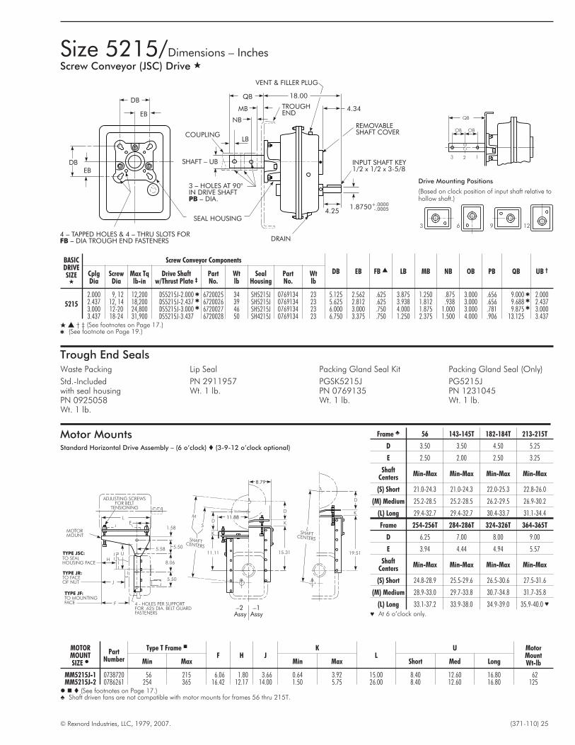
© Rexnord Industries, LLC, 1979, 2007. (371-110) 25
Size 5215/Dimensions – InchesScrew Conveyor (JSC) Drive �
Motor MountsStandard Horizontal Drive Assembly – (6 o’clock) � (3-9-12 o’clock optional)
DB
EB
DBEB
4 TAPPED HOLES & 4 THRU SLOTS FORDIA TROUGH END FASTENERSFB
– ––
SEAL HOUSING
VENT & FILLER PLUG
QB 18.00
TROUGHEND
4.34MB
NB
LBCOUPLING
SHAFT UB–
3 HOLES AT 90IN DRIVE SHAFT
DIA.PB
– °
–
DRAIN
4.25
REMOVABLESHAFT COVER
INPUT SHAFT KEY1/2 x 1/2 x 3-5/8
1.8750+.0000-.0005
3 6 9 12
Drive Mounting Positions
(Based on clock position of input shaft relative tohollow shaft.)
Trough End SealsWaste Packing
Std.-Includedwith seal housingPN 0925058Wt. 1 lb.
Lip Seal
PN 2911957Wt. 1 lb.
Packing Gland Seal Kit
PGSK5215JPN 0769135Wt. 1 lb.
Packing Gland Seal (Only)
PG5215JPN 1231045Wt. 1 lb.
3 2 1
OB OB
QB
BASICDRIVESIZE
�
Screw Conveyor Components
DB EB FB � LB MB NB OB PB QB UB †CplgDia
ScrewDia
Max Tqlb-in
Drive Shaftw/Thrust Plate ‡
PartNo.
Wtlb
SealHousing
PartNo.
Wtlb
5215
2.000 9, 12 12,200 DS5215J-2.000 � 6720025 34 SH5215J 0769134 23 5.125 2.562 .625 3.875 1.250 .875 3.000 .656 9.000 � 2.0002.437 12, 14 18,200 DS5215J-2.437 � 6720026 39 SH5215J 0769134 23 5.625 2.812 .625 3.938 1.812 .938 3.000 .656 9.688 � 2.4373.000 12-20 24,800 DS5215J-3.000 � 6720027 46 SH5215J 0769134 23 6.000 3.000 .750 4.000 1.875 1.000 3.000 .781 9.875 � 3.0003.437 18-24 31,900 DS5215J-3.437 6720028 50 SH4215J 0769134 23 6.750 3.375 .750 1.250 2.375 1.500 4.000 .906 13.125 3.437
� � † ‡ (See footnotes on Page 17.)� (See footnote on Page 19.)
Frame � 56 143-145T 182-184T 213-215T
D 3.50 3.50 4.50 5.25
E 2.50 2.00 2.50 3.25
ShaftCenters
Min-Max Min-Max Min-Max Min-Max
(S) Short 21.0-24.3 21.0-24.3 22.0-25.3 22.8-26.0
(M) Medium 25.2-28.5 25.2-28.5 26.2-29.5 26.9-30.2
(L) Long 29.4-32.7 29.4-32.7 30.4-33.7 31.1-34.4
Frame 254-256T 284-286T 324-326T 364-365T
D 6.25 7.00 8.00 9.00
E 3.94 4.44 4.94 5.57
ShaftCenters
Min-Max Min-Max Min-Max Min-Max
(S) Short 24.8-28.9 25.5-29.6 26.5-30.6 27.5-31.6
(M) Medium 28.9-33.0 29.7-33.8 30.7-34.8 31.7-35.8
(L) Long 33.1-37.2 33.9-38.0 34.9-39.0 35.9-40.0 �
� At 6 o’clock only.
MOTORMOUNTSIZE �
PartNumber
Type T Frame �
F H JK
LU Motor
MountWt-lbMin Max Min Max Short Med Long
MM5215J-1 0738720 56 215 6.06 1.80 3.66 0.64 3.92 15.00 8.40 12.60 16.80 62MM5215J-2 0786261 254 365 16.42 12.17 14.00 1.50 5.75 26.00 8.40 12.60 16.80 125� � � (See footnotes on Page 17.)� Shaft driven fans are not compatible with motor mounts for frames 56 thru 215T.
ADJUSTING SCREWSFOR BELT
TENSIONING
LE
MOTORMOUNT
1.58
5.505.58
8.06
5.50
4 - HOLES PER SUPPORTFOR .625 DIA. BELT GUARDFASTENERS
F
J
HU
TO SEALHOUSING FACE
TO FACEOF NUT
TO MOUNTINGFACE
15.31
K
D
K
DM
S
SHAFTCENTERS
D
K
19.51
LSHAFT
CENTERS
11.11TYPE JSC:
TYPE JR:
TYPE JF:
11.88
8.79
–2 –1Assy Assy

26 (371-110) © Rexnord Industries, LLC, 1979, 2007.
Size 5307/Dimensions – InchesShaft Mounted (JR) & Flange Mounted (JF) Drive �
TA Taper Bushings
5.00 1.59
SET SCREW
NUT
RETAININGRING
TAPEREDBUSHING
DRIVENSHAFT
HOLLOW SHAFTKEY (FURNISHED)
7.39
Style No. 1 — Thin-wall bushing
SET SCREW
NUT
RETAININGRING
TAPEREDBUSHING
HOLLOW SHAFTKEY (FURNISHED)
DRIVEN SHAFTSQUARE KEY(NOT FURNISHED)
Style No. 2 — Thick-wall bushingBUSHING
SIZEPart
Number ‡StyleNo.
DrivenShaft
Keyway/MinKey Length �
Wtlb
BU5307J-2.000 0769155 2 ½ x ¼ x 7 17.8BU5307J-2.188 0769156 2 ½ x ¼ x 7 16.6BU5307J-2.250 0769157 2 ½ x ¼ x 7 16.2BU5307J-2.438 0769158 2 5/8 x 5/16 x 5½ 14.9
BU5307J-2.500 0769159 2 5/8 x 5/16 x 5 14.4BU5307J-2.688 0769160 1 5/8 x 5/16 x 5 13.0BU5307J-2.938 0769161 1 3/4 x 3/8 x 5 10.9
BU5307J-3.000 0769162 1 3/4 x 3/8 x 5 10.3BU5307J-3.188 0769163 1 3/4 x 3/8 x 5 8.6BU5307J-3.438 0769164 1 7/8 x 7/16 x 5 6.1
‡ � (See footnotes on Page 16.)
BASICDRIVESIZE †
PartNumber
ExactRatio
MaxOutput
rpm
Wtlb
5307J05A 0794386 4.857 350 3555307J09A 0794387 9.131 190 3755307J14A 0794388 14.03 125 3755307J25A 0794389 25.26 70 375
� † (See footnotes on Page 16.)
Hollow Shaft Details
See Manual 377-140 for JF drive tapereddriven shaft recommendations. See Manual377-142 for JF drives using tapered bushings.
30 UP°
5 DOWN°
5°MAX.
10°MAX.0° INCLINE DOWN ON DRIVES
WITH BACKSTOPS IN 9 OR 12O'CLOCK MOUNTING.
INCLINE ROTATION
Angular Limits For Horizontal Mounting
(All Clock Positions)Refer to Factory for lubrication analysis of all inclined drives exceedingthe maximum specified below. Also for drives with combined inclinedown and rotation.
3–HOLES1 – 8 UNC x 1.50–TAP
4.750
.820
4.62 RADIUS
INPUT END COVER &BACKSTOP LOCATION
.820
MOUNTINGSURFACE
4.679
9.358
5.625 DIA. REGISTER+.002– .001
17.13
12.33 4.80
2.55 9.107.39 MIN10.69 MAX
1.76
6.06
REMOVABLESHAFT COVER
INPUT SHAFT KEY1/2 x 1/2 x 4
2.1250+.0000-.0005
4.75
DRAIN
7.10
1.00
2.62
3.25TORQUE ARMMAX. REACTION: 11,290 LBS.
2 – HOLES FOR 3/4 DIA.SAE GRADE 5 BOLTS
VENT &FILLER PLUG
17.12
8.56
8.56OILLEVEL
22.46
16.01
6.58 3.40
2º2º
30º MAX30º MAX
1 DIA.
6.50
8.62
ALTERNATEPOSITION
12.8 STD5.3 MIN
30 MIN35 MAX
SETSCREW
.125 DEEP
3.2 3.2
Accessories
Torque Arm
TA5307JPN 0785269Wt. 25 lb.
Backstop �
BS5307J09/14/25PN 0785529Wt. 3 lb.� Not available in 5:1 ratio.
Thrust Plate Kit
TP53075JPN 0769154Wt. 3 lb.
Vertical Breather
VB5307J-HSS UpPN 0786774VB5307J-HSS DownPN 0738470Wt. 7 lb. COMBINATION
DIPSTICK & VENT23.70
8.38
DRAIN
OILLEVEL
DRAIN
10.80
VENTEDFILLER PLUG
8.38
INPUT SHAFT DOWN INPUT SHAFT UP
Vertical Drives
Refer to Factory for lubrication analysis ofall vertical drives exceeding ±1° fromtrue vertical.
2.25
15.10
FANShaft Fan Kit
SFK5307JPN 0785530Wt. 4 lb.

© Rexnord Industries, LLC, 1979, 2007. (371-110) 27
Size 5307/Dimensions – InchesScrew Conveyor (JSC) Drive �
Trough End SealsWaste Packing
Std.-Includedwith seal housingPN 0925058Wt. 1 lb.
Lip Seal
PN 0912741Wt. 1 lb.
Packing Gland Seal Kit
PGSK5307JPN 0738466Wt. 1 lb.
Packing Gland Seal (Only)
PG5307JPN 1184315Wt. 1 lb.
DB
EB
DBEB
4 TAPPED HOLES & 4 THRU SLOTS FORDIA TROUGH END FASTENERSFB
– ––
SEAL HOUSING
VENT & FILLER PLUG
QB 19.36
TROUGHEND
4.80MB
NB
LBCOUPLING
SHAFT UB–
3 HOLES AT 90IN DRIVE SHAFT
DIA.PB
– °
–
DRAIN
4.75
REMOVABLESHAFT COVER
INPUT SHAFT KEY1/2 x 1/2 x 4
2.1250+.0000-.0005
3 6 9 12
Drive Mounting Positions
(Based on clock position of input shaft relative tohollow shaft.)
Motor MountsStandard Horizontal Drive Assembly – (6 o’clock) � (3-9-12 o’clock optional)
3 2 1
OB OB
QB
MOTORMOUNTSIZE �
PartNumber
Type T Frame �
F H JK
LU Motor
MountWt-lbMin Max Min Max Short Med Long
MM5307J-1 0738468 56 215 5.64 0.88 3.09 0.64 3.92 15.00 10.30 13.50 16.70 67MM5307J-2 0786373 254 404 16.00 11.26 13.46 1.50 5.75 25.50 10.30 13.50 16.70 140� � � (See footnotes on Page 17.)� (See footnote on Page 25.)
BASICDRIVESIZE
�
Screw Conveyor Components
DB EB FB � LB MB NB OB PB QB UB †CplgDia
ScrewDia
Max Tqlb-in
Drive Shaftw/Thrust Plate ‡
PartNo.
Wtlb
SealHousing
PartNo.
Wtlb
53072.437 12, 14 18,200 DS5307J-2.437 � 6720029 49 SH5307J 0769152 36 5.625 2.812 .625 3.938 1.812 .938 3.000 .656 9.688 � 2.4373.000 12-20 34,300 DS5307J-3.000 � 6720030 56 SH5307J 0769152 36 6.000 3.000 .750 4.000 1.875 1.000 3.000 .781 9.875 � 3.0003.437 18-24 51,400 DS5307J-3.437 � 6720031 70 SH5307J 0769152 36 6.750 3.375 .750 5.250 2.375 1.500 4.000 .906 13.125 � 3.437
� � † ‡ (See footnotes on Page 17.)� (See footnote on Page 19.)
Frame � 56 143-145T 182-184T 213-215T
D 3.50 3.50 4.50 5.25
E 2.50 2.00 2.50 3.25
ShaftCenters
Min-Max Min-Max Min-Max Min-Max
(S) Short 24.1-27.3 24.1-27.3 25.0-28.3 25.8-29.0
(M) Medium 27.2-30.5 27.2-30.5 28.2-31.5 29.0-32.2
(L) Long 30.4-33.7 30.4-33.7 31.4-34.7 32.1-35.4
Frame 254-256T 284-286T 324-326T 364-365T
D 6.25 7.00 8.00 9.00
E 3.43 3.93 4.43 5.06
ShaftCenters
Min-Max Min-Max Min-Max Min-Max
(S) Short 27.8-31.9 28.5-32.6 29.5-33.6 30.5-34.6
(M) Medium 31.0-35.0 31.7-35.8 32.7-36.8 33.7-37.8
(L) Long 34.1-38.2 34.9-39.0 35.9-40.0 36.9-41.0
Frame 404T
D 10.00
E 5.81
ShaftCenters
Min-Max
(S) Short 31.5-35.6
(M) Medium 34.7-38.8
(L) Long 37.9-42.0
ADJUSTING SCREWSFOR BELT
TENSIONING
LE
MOTORMOUNT
1.76
5.50
10.58
5.50
4-HOLES PER SUPPORTFOR .750 DIA. BELT GUARDFASTENERS
F
J
HUTYPE JSC:
TO SEALHOUSING FACE
TYPE JR:TO FACEOF NUT
TYPE JF:TO MOUNTINGFACE
16.30
K
D
K
D
M
S
SHAFTCENTERS
D
K
19.50
LSHAFT
CENTERS
13.10
5.72
13.13
9.85
–2 –1Assy Assy

28 (371-110) © Rexnord Industries, LLC, 1979, 2007.
Size 5315/Dimensions – InchesShaft Mounted (JR) & Flange Mounted (JF) Drive �
TA Taper Bushings
5.00 1.88
SET SCREW
NUT
RETAININGRING
TAPEREDBUSHING
DRIVENSHAFT
HOLLOW SHAFTKEY (FURNISHED)
7.92
Style No. 1 — Thin-wall bushing
SET SCREW
NUT
RETAININGRING
TAPEREDBUSHING
HOLLOW SHAFTKEY (FURNISHED)
DRIVEN SHAFTSQUARE KEY(NOT FURNISHED)
Style No. 2 — Thick-wall bushing
BUSHINGSIZE
PartNumber ‡
StyleNo.
DrivenShaft
Keyway/MinKey Length �
Wtlb
BU5315J-2.438 0785778 2 5/8 x 5/16 x 7½ 23.6BU5315J-2.500 0785779 2 5/8 x 5/16 x 7½ 23.1BU5315J-2.688 0785780 2 5/8 x 5/16 x 7½ 21.6BU5315J-2.938 0785781 2 ¾ x 3/8 x 5½ 19.4
BU5315J-3.000 0785782 2 ¾ x 3/8 x 5½ 18.8BU5315J-3.438 0785783 1 7/8 x 7/16 x 5 14.3BU5315J-3.938 0785784 1 1 x ½ x 5 8.4
‡ � (See footnotes on Page 16.)
BASICDRIVESIZE †
PartNumber
ExactRatio
MaxOutput
rpm
Wtlb
5315J05A 0794390 4.857 350 3755315J09A 0794391 9.131 190 4005315J14A 0794392 13.91 125 4005315J25A 0794393 25.26 70 400
� † (See footnotes on Page 16.)
Hollow Shaft Details
See Manual 377-140 for JF drive tapereddriven shaft recommendations. See Manual377-142 for JF drives using tapered bushings.
20 UP°
5 DOWN°
5°MAX.
10°MAX.0° INCLINE DOWN ON DRIVES
WITH BACKSTOPS IN 9 OR 12O'CLOCK MOUNTING.
INCLINE ROTATION
Angular Limits For Horizontal Mounting
(All Clock Positions)Refer to Factory for lubrication analysis of all inclined drivesexceeding the maximum specified below. Also for drives withcombined incline down and rotation.
3–HOLES1 – 8 UNC x 1.50–TAP
4.750
.820
4.40 RADIUS
INPUT END COVER &BACKSTOP LOCATION
.820
MOUNTINGSURFACE
4.679
9.358
18.66
13.25 5.41
2.58 9.977.92 MIN10.74 MAX
1.80
6.81
REMOVABLESHAFT COVER
INPUT SHAFT KEY1/2 x 1/2 x 4-1/2
5.25
DRAIN
7.57
1.12
3.12
3.88TORQUE ARMMAX. REACTION: 15,880 LBS.
2 – HOLES FOR 1.0 DIA.SAE GRADE 5 BOLTS
VENT &FILLER PLUG
17.12
8.56
8.56OILLEVEL
22.46
16.01
6.58 3.40
2º2º
30º MAX30º MAX
1-1/4 DIA.
7.00
9.62
ALTERNATEPOSITION
12.8 STD4.8 MIN
30 MIN35 MAX
SETSCREW
2.2500+.0000– .0005
3.2 3.2
6.375 DIA. REGISTER+.002– .002
.125 DEEP
Accessories
Torque Arm
TA5315JPN 0785270Wt. 38 lb.
Backstop �
BS5315J09/14/25PN 0757183Wt. 7 lb.� Not available in 5:1 ratio.
Thrust Plate Kit
TP5315JPN 0769207Wt. 4 lb.
Vertical Breather
VB5315J-HSS UpPN 0738471VB5315J-HSS DownPN 0738470Wt. 7 lb. COMBINATION
DIPSTICK & VENT23.10
8.38
DRAIN
OILLEVEL
DRAIN
10.40
VENTEDFILLER PLUG
8.38
INPUT SHAFT DOWN INPUT SHAFT UP
Vertical Drives
Refer to Factory for lubrication analysis ofall vertical drives exceeding ±1° fromtrue vertical.
FAN15.10
2.84
Shaft Fan Kit
SFK5315JPN 0785432Wt. 4 lb.

© Rexnord Industries, LLC, 1979, 2007. (371-110) 29
Size 5315/Dimension – InchesScrew Conveyor (JSC) Drive �
Trough End SealsWaste Packing
Std.-Includedwith seal housingPN 0925058Wt. 1 lb.
Lip Seal
PN 0912741Wt. 1 lb.
Packing Gland Seal Kit
PGSK5315JPN 0738466Wt. 1 lb.
Packing Gland Seal (Only)
PG5315JPN 1184315Wt. 1 lb.
DB
EB
DBEB
4 TAPPED HOLES & 4 THRU SLOTS FORDIA TROUGH END FASTENERSFB
– ––
SEAL HOUSING
VENT & FILLER PLUG
QB 20.88
TROUGHEND
5.41MB
NB
LBCOUPLING
SHAFT UB–
3 HOLES AT 90IN DRIVE SHAFT
DIA.PB
– °
–
DRAIN
5.25
REMOVABLESHAFT COVER
INPUT SHAFT KEY1/2 x 1/2 x 4-1/2
2.2500 +.0000– .0005
3 6 9 12
Drive Mounting Positions
(Based on clock position of input shaft relative tohollow shaft.)
Motor MountsStandard Horizontal Drive Assembly – (6 o’clock) � (3-9-12 o’clock optional)
3 2 1
OB OB
QB
BASICDRIVESIZE
�
Screw Conveyor Components
DB EB FB � LB MB NB OB PB QB UB †CplgDia
ScrewDia
Max Tqlb-in
Drive Shaftw/Thrust Plate ‡
PartNo.
Wtlb
SealHousing
PartNo.
Wtlb
53152.437 12, 14 18,220 DS5315J-2.437 � 6720032 58 SH5315J 0769206 36 5.625 2.812 .625 3.938 1.812 .938 3.000 .656 9.688 � 2.4373.000 12-20 34,300 DS5315J-3.000 � 6720033 65 SH5315J 0769206 36 6.000 3.000 .750 4.000 1.875 1.000 3.000 .781 9.875 � 3.0003.438 18-24 51,400 DS5315J-3.437 � 6720034 80 SH5315J 0769206 36 6.750 3.375 .750 5.250 2.375 1.500 4.000 .906 13.125 � 3.437
� � † ‡ (See footnotes on Page 17.)� (See footnote on Page 19.)
MOTORMOUNTSIZE �
PartNumber
Type T Frame �
F H JK
LU Motor
MountWt-lbMin Max Min Max Short Med Long
MM5315J-1 0738468 56 215 5.20 0.44 2.62 0.64 3.92 15.00 10.92 14.12 17.32 67MM5315J-2 0786373 254 405 15.60 10.83 13.00 1.50 5.75 25.50 10.92 14.12 17.32 140� � � (See footnotes on Page 17.)� (See footnote on Page 25.)
Frame � 56 143-145T 182-184T 213-215T
D 3.50 3.50 4.50 5.25
E 2.50 2.00 2.50 3.25
ShaftCenters
Min-Max Min-Max Min-Max Min-Max
(S) Short 24.1-27.3 24.1-27.3 25.0-28.3 25.8-29.0
(M) Medium 27.2-30.5 27.2-30.5 28.2-31.5 29.0-32.2
(L) Long 30.4-33.7 30.4-33.7 31.4-34.7 32.1-35.4
Frame 254-256T 284-286T 324-326T 364-365T
D 6.25 7.00 8.00 9.00
E 3.43 3.93 4.43 5.06
ShaftCenters
Min-Max Min-Max Min-Max Min-Max
(S) Short 27.8-31.9 28.5-32.6 29.5-33.6 30.5-34.6
(M) Medium 31.0-35.0 31.7-35.8 32.7-36.8 33.7-37.8
(L) Long 34.1-38.2 34.9-39.0 35.9-40.0 36.9-41.0
Frame 404-405T
D 10.00
E 5.81
ShaftCenters
Min-Max
(S) Short 31.5-35.6
(M) Medium 34.7-38.8
(L) Long 37.9-42.0
ADJUSTING SCREWSFOR BELT
TENSIONING
L
E
MOTORMOUNT
1.76
5.505.72
10.58
5.50
4-HOLES PER SUPPORTFOR .750 DIA. BELT GUARDFASTENERS
F
J
H
UTYPE JSC:TO SEALHOUSING FACE
TYPE JR:TO FACEOF NUT
TYPE JF:TO MOUNTINGFACE
16.30
K
D
K
D
M
S
SHAFTCENTERS
D
K
19.50
LSHAFT
CENTERS
13.10
13.13
9.85
–2 –1Assy Assy
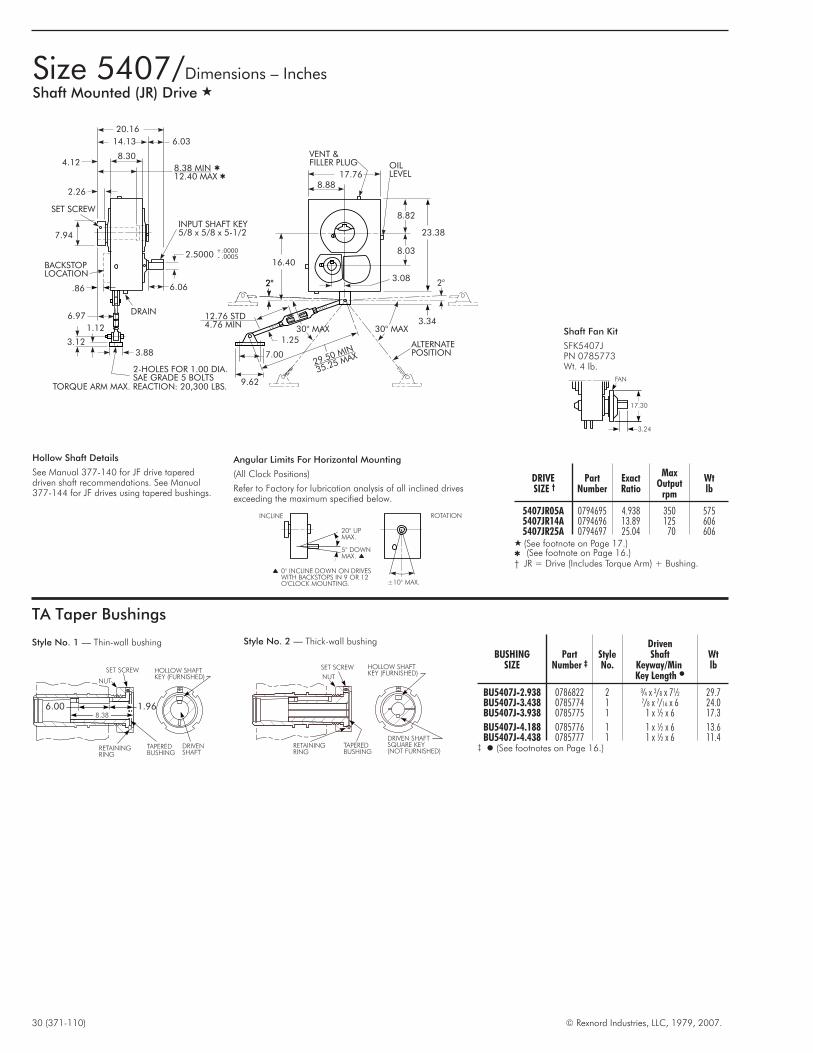
30 (371-110) © Rexnord Industries, LLC, 1979, 2007.
Size 5407/Dimensions – InchesShaft Mounted (JR) Drive �
TA Taper Bushings
6.00 1.96
SET SCREW
NUT
RETAININGRING
TAPEREDBUSHING
DRIVENSHAFT
HOLLOW SHAFTKEY (FURNISHED)
8.38
Style No. 1 — Thin-wall bushing
SET SCREW
NUT
RETAININGRING
TAPEREDBUSHING
HOLLOW SHAFTKEY (FURNISHED)
DRIVEN SHAFTSQUARE KEY(NOT FURNISHED)
Style No. 2 — Thick-wall bushing
BUSHINGSIZE
PartNumber ‡
StyleNo.
DrivenShaft
Keyway/MinKey Length �
Wtlb
BU5407J-2.938 0786822 2 ¾ x 3/8 x 7½ 29.7BU5407J-3.438 0785774 1 7/8 x 7/16 x 6 24.0BU5407J-3.938 0785775 1 1 x ½ x 6 17.3
BU5407J-4.188 0785776 1 1 x ½ x 6 13.6BU5407J-4.438 0785777 1 1 x ½ x 6 11.4
‡ � (See footnotes on Page 16.)
DRIVESIZE †
PartNumber
ExactRatio
MaxOutput
rpm
Wtlb
5407JR05A 0794695 4.938 350 5755407JR14A 0794696 13.89 125 6065407JR25A 0794697 25.04 70 606
� (See footnote on Page 17.)� (See footnote on Page 16.)† JR = Drive (Includes Torque Arm) + Bushing.
Hollow Shaft Details
See Manual 377-140 for JF drive tapereddriven shaft recommendations. See Manual377-144 for JF drives using tapered bushings.
20 UPMAX.
5 DOWNMAX.
°
°
±10 MAX.°
INCLINE ROTATION
0° INCLINE DOWN ON DRIVESWITH BACKSTOPS IN 9 OR 12O'CLOCK MOUNTING.
Angular Limits For Horizontal Mounting
(All Clock Positions)
Refer to Factory for lubrication analysis of all inclined drivesexceeding the maximum specified below.
20.16
14.13
8.30
6.03
4.128.38 MIN12.40 MAX
2.26
SET SCREW
7.94
BACKSTOPLOCATION
6.97
1.12
3.123.88
2-HOLES FOR 1.00 DIA.SAE GRADE 5 BOLTS
TORQUE ARM MAX. REACTION: 20,300 LBS.
6.06
2.5000
INPUT SHAFT KEY5/8 x 5/8 x 5-1/2
+.0000- .0005
VENT &FILLER PLUG
17.768.88
OILLEVEL
23.38
3.08
16.40
8.82
8.03
12.76 STD4.76 MIN
1.25
7.00
9.62
ALTERNATEPOSITION
29.50 MIN
35.25 MAX
2°
30° MAX
DRAIN
.86
3.34
2° 2°
30° MAX
3.24
FAN
17.30
Shaft Fan Kit
SFK5407JPN 0785773Wt. 4 lb.

© Rexnord Industries, LLC, 1979, 2007. (371-110) 31
Size 5407/Dimensions – InchesFlange Mounted (JF) Drive �
11.25
5.629.25
4.625 4-HOLES FOR.750-DIA. BOLTS
5.629.25
11.25
4.625
3.08
8.88
17.76
3.50
5.250 C'BOREDEEP.88-
+.003-.000
REGISTER
VENT &FILLER PLUG
20.56
14.53 6.03
2.08
8.82
2.5000
6.04
DRAIN
1.25 MIN
+.0000- .0005
INPUT SHAFT KEY5/8 x 5/8 x 5-1/2
23.38
OIL LEVEL
8.03
BACKSTOPLOCATION
20 UPMAX.
5 DOWNMAX.
°
°
±10 MAX.°
INCLINE ROTATION
0° INCLINE DOWN ON DRIVESWITH BACKSTOPS IN 9 OR 12O'CLOCK MOUNTING.
Angular Limits For Horizontal Mounting
(All Clock Positions)Refer to Factory for lubrication analysis of all inclined drivesexceeding the maximum specified below.
DRIVESIZE †
PartNumber
ExactRatio
MaxOutput
rpm
Wtlb
5407JF05A 0794394 4.938 350 5405407JF14A 0794395 13.89 125 6105407JF25A 0794396 25.04 70 610
† JF = Drive (Includes Output Flange) (Bushing Optional).
Hollow Shaft Details
See Manual 377-140 for JF drive tapered drivenshaft recommendations. See Manual 377-144for JF drives using tapered bushings.
Torque Arm
TA5407JPN 0785271Wt. 35 lb.
Backstop �
BS5407J14/25PN 0769170Wt. 23 lb.� Not available in 5:1 ratio.
Thrust Plate Kit
TP5407JPN 0769176Wt. 5 lb.
Vertical Breather
VB5407J-HSS Up W/O FanPN 0757208VB5407J-HSS Down W/O FanPN 0757209VB5407J-HSS Up With FanPN 0765839VB5407J-HSS Down With FanPN 0765840Wt. 7 lb.
DIPSTICKASSEMBLY
10.07
21.76
INPUT SHAFT DOWN
24.30
10.07
INPUT SHAFT UP
Vertical Drives
Refer to Factory for lubrication analysis ofall vertical drives exceeding ±1° fromtrue vertical.
Accessories
36
912
Drive Mounting Positions
(Based on clock position of input shaft relative to hollow shaft.)
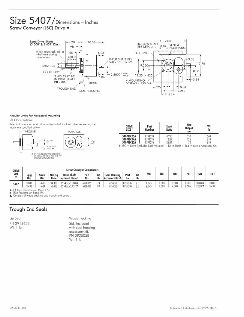
32 (371-110) © Rexnord Industries, LLC, 1979, 2007.
Size 5407/Dimensions – InchesScrew Conveyor (JSC) Drive �
Trough End Seals
Lip Seal
PN 2913658Wt. 1 lb.
DRIVESIZE †
PartNumber
ExactRatio
MaxOutput
rpm
Wtlb
5407JSC05A 0794394 4.938 350 5405407JSC14A 0794395 13.89 125 6105407JSC25A 0794396 25.04 70 610
† JSC = Drive (Includes Seal Housing) + Drive Shaft + Seal Housing Accessory Kit.
20° UPMAX.
5° DOWNMAX.
±10°MAX.
INCLINE ROTATION
0° INCLINE DOWN ON DRIVESWITH BACKSTOPS IN 9 OR 12O'CLOCK MOUNTING
Angular Limits For Horizontal Mounting
(All Clock Positions)
Refer to Factory for lubrication analysis of all inclined drives exceeding themaximum specified below.
Long Drive Shafts(3.000" & 3.437" Dia.)
QB 20.56
MB
NB
OBOB
SHAFT-UB
2 HOLES AT 90°IN DRIVE SHAFT
- DIA.PB
COUPLING
6.03
INPUT SHAFT KEY5/8 x 5/8 x 5-1/2
2.5000 +.0000- .0005
6.06
DRAIN
SEAL HOUSINGTROUGH END
23.38
8.82 VENT &FILLER PLUG
HOLLOW SHAFT(SEE DETAIL)
OIL LEVEL
3.08
17.76
8.88
3.34
9.250
11.25 4.625
4 MOUNTINGSCREWS - .750 DIA.
4.625 8.03
9.25011.25
When required, drill athird hole duringinstallation.
DRIVESIZE
�
Screw Conveyor Components
MB NB OB PB QB UB †CplgDia
ScrewDia
Max Tqlb-in
Drive Shaftw/Thrust Plate ‡
PartNo.
Wtlb
Seal HousingAccessory Kit �
PartNo.
Wtlb
5407 3.000 14-20 34,300 DS5407J-3.000 � 6720035 74 SH5407J 0757205 2.5 1.875 1.000 3.000 0.781 10.00 � 3.0003.438 16-24 51,400 DS5407J-3.437 � 6720036 89 SH5407J 0757205 2.5 2.375 1.500 4.000 0.906 13.28 � 3.437
� † ‡ (See footnotes on Page 17.)� (See footnote on Page 19.)� Consists of waste packing and trough end gasket.
Waste Packing
Std.-Includedwith seal housingaccessory kit.PN 0925058Wt. 1 lb.
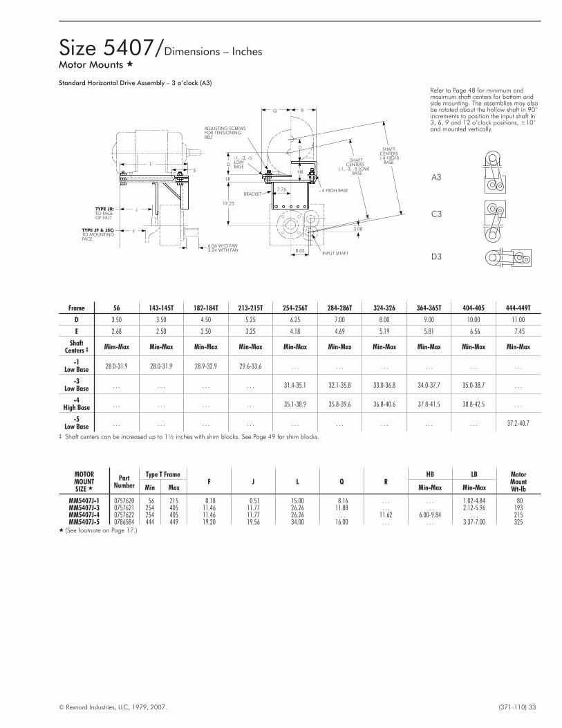
© Rexnord Industries, LLC, 1979, 2007. (371-110) 33
Size 5407/Dimensions – InchesMotor Mounts �
L
E
J
F
TYPE JR:TO FACEOF NUT
TYPE JF & JSC:TO MOUNTINGFACE
8.03
19.23
BRACKET
INPUT SHAFT
- 4 HIGH BASE
HB
D
-1, -3, -5LOWBASE
D
ADJUSTING SCREWSFOR TENSIONINGBELT
SHAFTCENTERS
(-1, -3, -5 LOW)BASE
SHAFTCENTERS(-4 HIGH)
BASE
Q R
7.76
3.08
LB
6.06 W/O FAN3.24 WITH FAN
Standard Horizontal Drive Assembly – 3 o’clock (A3)
MOTORMOUNTSIZE �
PartNumber
Type T FrameF J L Q R
HB LB MotorMountWt-lbMin Max Min-Max Min-Max
MM5407J-1 0757620 56 215 0.18 0.51 15.00 8.16 . . . . . . 1.02-4.84 80MM5407J-3 0757621 254 405 11.46 11.77 26.26 11.88 . . . . . . 2.12-5.96 193MM5407J-4 0757622 254 405 11.46 11.77 26.26 . . . 11.62 6.00-9.84 . . . 215MM5407J-5 0786584 444 449 19.20 19.56 34.00 16.00 . . . . . . 3.37-7.00 325
� (See footnote on Page 17.)
Frame 56 143-145T 182-184T 213-215T 254-256T 284-286T 324-326 364-365T 404-405 444-449T
D 3.50 3.50 4.50 5.25 6.25 7.00 8.00 9.00 10.00 11.00
E 2.68 2.50 2.50 3.25 4.18 4.69 5.19 5.81 6.56 7.45
ShaftCenters ‡ Mim-Max Min-Max Min-Max Min-Max Min-Max Min-Max Min-Max Min-Max Min-Max Min-Max
-1Low Base 28.0-31.9 28.0-31.9 28.9-32.9 29.6-33.6 . . . . . . . . . . . . . . . . . .
-3Low Base . . . . . . . . . . . . 31.4-35.1 32.1-35.8 33.0-36.8 34.0-37.7 35.0-38.7 . . .
-4High Base . . . . . . . . . . . . 35.1-38.9 35.8-39.6 36.8-40.6 37.8-41.5 38.8-42.5 . . .
-5Low Base . . . . . . . . . . . . . . . . . . . . . . . . . . . 37.2-40.7
‡ Shaft centers can be increased up to 1½ inches with shim blocks. See Page 49 for shim blocks.
A3
C3
D3
Refer to Page 48 for minimum andmaximum shaft centers for bottom andside mounting. The assemblies may alsobe rotated about the hollow shaft in 90°increments to position the input shaft in3, 6, 9 and 12 o’clock positions, ±10°and mounted vertically.

34 (371-110) © Rexnord Industries, LLC, 1979, 2007.
Size 5415/Dimensions – InchesShaft Mounted (JR) Drive �
TA Taper Bushings
7.50 2.06
SET SCREW
NUT
RETAININGRING
TAPEREDBUSHING
DRIVENSHAFT
HOLLOW SHAFTKEY (FURNISHED)
10.33
Style No. 1 — Thin-wall bushing
SET SCREW
NUT
RETAININGRING
TAPEREDBUSHING
HOLLOW SHAFTKEY (FURNISHED)
DRIVEN SHAFTSQUARE KEY(NOT FURNISHED)
Style No. 2 — Thick-wall bushing
BUSHINGSIZE
PartNumber ‡
StyleNo.
DrivenShaft
Keyway/MinKey Length �
Wtlb
BU5415J-3.438 0769234 2 7/8 X 7/16 X 8 41.5BU5415J-3.938 0769235 2 1 X ½ X 6 33.8BU5415J-4.188 0769236 1 1 X ½ X 7½ 29.5
BU5415J-4.438 0769237 1 1 X ½ X 7½ 24.9BU5415J-4.938 0769238 1 1¼ X 5/8 X 7½ 15.1
‡ � (See footnotes on Page 16.)
DRIVESIZE †
PartNumber
ExactRatio
MaxOutput
rpm
Wtlb
5415JR05 0794698 5.077 350 7655415JR14A 0794699 13.61 125 7955415JR25A 0794700 26.11 70 795
� (See footnote on Page 16.)† (See footnote on Page 30.)
Hollow Shaft Details
See Manual 377-140 for JF drive tapered drivenshaft recommendations. See Manual 377-144 forJF drives using tapered bushings.
20 UPMAX.
5 DOWNMAX.
°
°
±10 MAX.°
INCLINE ROTATION
0° INCLINE DOWN ON DRIVESWITH BACKSTOPS IN 9 OR 12O'CLOCK MOUNTING.
Angular Limits For Horizontal Mounting
(All Clock Positions)
Refer to Factory for lubrication analysis of all inclineddrives exceeding the maximum specified below.
23.24
17.08
10.30
6.16
4.4910.33 MIN13.44 MAX
2.20
SET SCREW
8.88
1.49
BACKSTOPLOCATION
7.93
1.25
3.50
4.38
2-HOLES FOR 1.25 DIA.SAE GRADE 5 BOLTS
TORQUE ARM MAX. REACTION: 26,100 LBS.
6.76
2.5000
INPUT SHAFT KEY5/8 x 5/8 x 6
+.0000- .0005
VENT &FILLER PLUG
18.869.43
OILLEVEL
25.26
4.083.38
17.60
9.42
8.02
11.00 STD5.40 MIN
1.50
8.62
11.62
ALTERNATEPOSITION29.50 MIN
35.25 MAX
2°
30° MAX
DRAIN
2°
30° MAX
AccessoriesTorque Arm
TA5415JPN 0785272Wt. 56 lb.
Backstop �
BS5415J14PN 0757220BS5415J25PN 0757221Wt. 22 lb.� Not available in 5:1 ratio.
Thrust Plate Kit
TP5415JPN 0769233Wt. 8 lb.
Vertical Breather
VB5415J-HSS Up W/O FanPN 0757223VB5415J-HSS Down W/O FanPN 0757224VB5415J-HSS Up With FanPN 0765841VB5415J-HSS Down With FanPN 0765842Wt. 8 lb.
DIPSTICKASSEMBLY
10.73
21.30
INPUT SHAFT DOWN
19.06
10.73
INPUT SHAFT UP
Vertical Drives
Refer to Factory for lubrication analysis ofall vertical drives exceeding ±1° fromtrue vertical.
3.44
FAN
17.30
Shaft Fan Kit
SFK5415JPN 0785881Wt. 4 lb.
36
912
Drive Mounting Positions
(Based on clock position of input shaft relative to hollowshaft.)
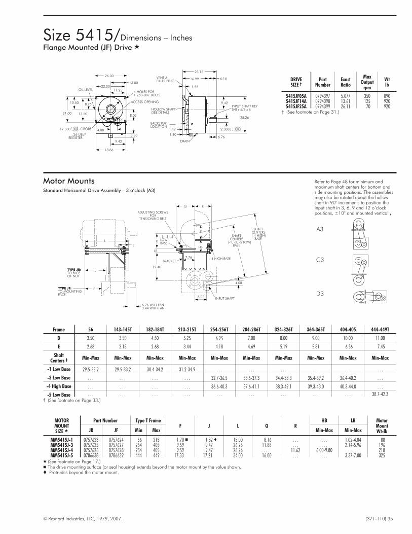
© Rexnord Industries, LLC, 1979, 2007. (371-110) 35
Size 5415/Dimensions – InchesFlange Mounted (JF) Drive �
Motor MountsStandard Horizontal Drive Assembly – 3 o’clock (A3)
26.00
22.5011.25
13.00
OIL LEVEL
21.00
10.50
17.50
8.75
4-HOLES FOR1.250-DIA. BOLTS
ACCESS OPENING
8.02
3.50
9.42
18.86
17.500+.005-.000 -C'BORE
.26-DEEPREGISTER
4.08
23.15
VENT &FILLER PLUG
16.99 6.16
1.55
9.42INPUT SHAFT KEY5/8 x 5/8 x 6
25.26
2.5000+.0000– .0005
6.76DRAIN
1.40
1.12
BACKSTOPLOCATION
HOLLOW SHAFT(SEE DETAIL)
Refer to Page 48 for minimum andmaximum shaft centers for bottom andside mounting positions. The assembliesmay also be rotated about the hollowshaft in 90° increments to position theinput shaft in 3, 6, 9 and 12 o’clockpositions, ±10° and mounted vertically.
A3
C3
D3
Frame 56 143-145T 182-184T 213-215T 254-256T 284-286T 324-326T 364-365T 404-405 444-449T
D 3.50 3.50 4.50 5.25 6.25 7.00 8.00 9.00 10.00 11.00
E 2.68 2.18 2.68 3.44 4.18 4.69 5.19 5.81 6.56 7.45
ShaftCenters ‡ Min-Max Min-Max Min-Max Min-Max Min-Max Min-Max Min-Max Min-Max Min-Max Min-Max
-1 Low Base 29.5-33.2 29.5-33.2 30.4-34.2 31.2-34.9 . . . . . . . . . . . . . . . . . .
-3 Low Base . . . . . . . . . . . . 32.7-36.5 33.5-37.3 34.4-38.3 35.4-39.2 36.4-40.2 . . .
-4 High Base . . . . . . . . . . . . 36.6-40.3 37.6-41.1 38.3-42.1 39.3-43.0 40.3-44.0 . . .
-5 Low Base . . . . . . . . . . . . . . . . . . . . . . . . . . . 38.7-42.3‡ (See footnote on Page 33.)
MOTORMOUNTSIZE �
Part Number Type T FrameF J L Q R
HB LB MotorMountWt-lbJR JF Min Max Min-Max Min-Max
MM5415J-1 0757623 0757624 56 215 1.70 � 1.82 � 15.00 8.16 . . . . . . 1.02-4.84 88MM5415J-3 0757625 0757627 254 405 9.59 9.47 26.26 11.88 . . . . . . 2.14-5.96 196MM5415J-4 0757626 0757628 254 405 9.59 9.47 26.26 . . . 11.62 6.00-9.80 . . . 218MM5415J-5 0786638 0786639 444 449 17.33 17.21 34.00 16.00 . . . . . . 3.37-7.00 325
� (See footnote on Page 17.)� The drive mounting surface (or seal housing) extends beyond the motor mount by the value shown.� Protrudes beyond the motor mount.
DRIVESIZE †
PartNumber
ExactRatio
MaxOutput
rpm
Wtlb
5415JF05A 0794397 5.077 350 8905415JF14A 0794398 13.61 125 9205415JF25A 0794399 26.11 70 920
† (See footnote on Page 31.)
L
E
J
F
TYPE JR:TO FACEOF NUT
TYPE JF:TO MOUNTINGFACE
8.02
19.40
BRACKET
INPUT SHAFT
- 4 HIGH BASE
HB
D
-1, -3, -5LOWBASE
D
ADJUSTING SCREWSFOR
TENSIONING BELT
SHAFTCENTERS
(-1, -3, -5 LOW)BASE
SHAFTCENTERS(-4 HIGH)
BASE
Q R
7.76
4.08
LB
6.76 W/O FAN3.44 WITH FAN

36 (371-110) © Rexnord Industries, LLC, 1979, 2007.
Size 5507/Dimensions – InchesShaft Mounted (JR) Drive �
TA Taper Bushings
7.75 2.12
SET SCREWNUT
RETAININGRING
TAPEREDBUSHING
DRIVENSHAFT
HOLLOW SHAFTKEY (FURNISHED)
10.66
Style No. 1 — Thin-wall bushing
SET SCREW
NUT
RETAININGRING
TAPEREDBUSHING
HOLLOW SHAFTKEY (FURNISHED)
DRIVEN SHAFTSQUARE KEY(NOT FURNISHED)
Style No. 2 — Thick-wall bushing
BUSHINGSIZE
PartNumber ‡
StyleNo.
DrivenShaft
Keyway/MinKey Length �
Wtlb
BU5507J-3.438 0786824 2 7/8 x 7/16 x 10 56.8BU5507J-3.938 0786825 2 1 x ½ x 10 48.8BU5507J-4.438 0786826 2 1 x ½ x 10 40.0
BU5507J-4.938 0785894 1 1¼ x 5/8 x 7¾ 40.0BU5507J-5.438 0785895 1 1¼ x 5/8 x 7¾ 18.2
‡ � (See footnotes on Page 16.)
DRIVESIZE †
PartNumber � Exact
Ratio
MaxOutput
rpm
WtlbW/O
BackstopWith
BackstopFor
Backstop
5507JR05A 0794406 . . . . . . 4.929 � 350 . . .5507JR14A 0794407 0795667 0794409 13.46 125 10655507JR25A 0794408 0795668 0794410 24.29 70 1065
� (See footnote on Page 16.)† (See footnote on Page 30.)� Non-stock, Refer to Factory.� These part numbers do not include bushing.
Hollow Shaft Details
See Manual 377-140 for JF drive tapered drivenshaft recommendations. See Manual 377-144 forJF drives using tapered bushings.
20 UPMAX.
5 DOWNMAX.
°
°
±10 MAX.°
INCLINE ROTATION
5° INCLINE ON DRIVESWITH BACKSTOP IN ALLMOUNTING POSITIONS
Angular Limits For Horizontal Mounting
(All Clock Positions)
Refer to Factory for lubrication analysis of all inclineddrives exceeding the maximum specified below.
1.80
24.48
17.72
10.74
6.76
4.6810.66 MIN14.53 MAX
2.26
SET SCREW
9.38
BACKSTOPLOCATION
8.10
1.25
3.50
4.38
2-HOLES FOR 1.25 DIA.SAE GRADE 5 BOLTS
TORQUE ARM MAX. REACTION: 32,900 LBS.
7.40
2.7500
INPUT SHAFT KEY5/8 x 5/8 x 6-1/2
+.0000- .0005
VENT &FILLER PLUG
21.3210.66
OILLEVEL
29.10
5.163.66
20.34
10.66
9.29
11.00 STD5.40 MIN
1.50
8.62
11.62
ALTERNATEPOSITION29.50 MIN
35.25 MAX
2°
30° MAX
DRAIN
2°
30° MAX
AccessoriesTorque Arm
TA5507JPN 0785272Wt. 56 lb.
Thrust Plate Kit
TP5507JPN 0769221Wt. 9 lb.
Vertical Breather
VB5507J-HSS Up W/O FanPN 0757223VB5507J-HSS Down W/O FanPN 0757224VB5507J-HSS Up With FanPN 0765841VB5507J-HSS Down With FanPN 0765842Wt. 8 lb.
DIPSTICKASSEMBLY
11.48
21.28
INPUT SHAFT DOWN
18.30
11.48
INPUT SHAFT UP
Vertical Drives
Refer to Factory for lubrication analysisof all vertical drives exceeding ±1°fromtrue vertical.
FAN
3.59
19.00
Shaft Fan Kit
SFK5507JPN 0785893Wt. 5 lb.
36
912
Drive Mounting Positions
(Based on clock position of input shaft relative to hollowshaft.)
Backstop
BS5507J14#0793687
BS5507J25#0793688

© Rexnord Industries, LLC, 1979, 2007. (371-110) 37
Size 5507/Dimensions – InchesFlange Mounted (JF) Drive � (Not available with backstop)
Motor MountsStandard Horizontal Drive Assembly – 3 o’clock (A3)
26.00
22.5011.25
13.00
OIL LEVEL
21.00
10.50
17.50
8.75
4-HOLES FOR1.250-DIA. BOLTS
ACCESS OPENING
9.29
3.75
10.66
21.32
17.500+.005-.000 -C'BORE
.26-DEEPREGISTER
5.16
24.20
VENT &FILLER PLUG
17.44 6.76
1.29
9.42INPUT SHAFT KEY5/8 x 5/8 x 6-1/2
29.10
2.7500+.0000- .0005
7.40
DRAIN
1.12
HOLLOW SHAFT(SEE DETAIL)
Refer to Page 48 for minimum andmaximum shaft centers for bottom andside mounting positions. The assembliesmay also be rotated about the hollowshaft in 90° increments to position theinput shaft in 3, 6, 9 and 12 o’clockpositions, ±10° and mounted vertically.
A3
C3
D3
Frame 56 143-145T 182-184T 213-215T 254-256T 284-286T 324-326T 364-365T 404-405T 444-449T
D 3.50 3.50 4.50 5.25 6.25 7.00 8.00 9.00 10.00 11.00
E 2.68 2.18 2.68 3.44 4.18 4.69 5.19 5.81 6.56 7.44
ShaftCenters ‡ Min-Max Min-Max Min-Max Min-Max Min-Max Min-Max Min-Max Min-Max Min-Max Min-Max
-1 Low Base 31.5-35.5 31.5-35.5 32.5-36.5 33.2-37.2 . . . . . . . . . . . . . . . . . .
-3 Low Base . . . . . . . . . . . . 34.9-38.7 35.7-39.4 36.6-40.4 37.6-41.4 38.6-42.4 . . .
-4 High Base . . . . . . . . . . . . 38.7-42.5 39.5-43.2 40.5-44.2 41.4-45.2 42.4-46.2 . . .
-5 Low Base . . . . . . . . . . . . . . . . . . . . . . . . . . . 46.1-49.8‡ (See footnote on Page 33.)
MOTORMOUNTSIZE �
Part Number Type T FrameF J L O Q R U
HB LB MotorMountWt-lbJR JF Min Max Min-Max Min-Max
MM5507J-1 0757239 0757240 56 215 2.17 � 2.51 � 15.00 7.76 8.16 . . . 21.03 . . . 1.02-5.08 111MM5507J-3 0757241 0757243 254 405 9.12 8.78 26.26 7.76 11.88 . . . 20.64 . . . 2.12-5.96 224MM5507J-4 0757242 0757244 254 405 9.12 8.78 26.26 7.76 . . . 11.62 20.64 6.00-9.84 . . . 246MM5507J-5 0769048 0769049 444 449 16.47 16.15 34.00 11.25 16.00 . . . 27.41 . . . 2.00-5.75 438
� (See footnote on Page 17.)� � (See footnotes on Page 35.)
DRIVESIZE †
PartNumber
ExactRatio
MaxOutput
rpm
Wtlb
5507JF05A 0794411 4.929 � 350 . . .5507JF14A 0794412 13.46 125 12005507JF25A 0794413 24.29 70 1200
† (See footnote on Page 31.)� Non-stock, Refer to Factory.
L
E
J
F
TYPE JR:TO FACEOF NUT
TYPE JF:TO MOUNTINGFACE
U
BRACKET - 4 HIGH BASE
HB
D-1, -3, -5
LOWBASE
D
ADJUSTING SCREWSFOR
TENSIONING BELT
SHAFTCENTERS
(-1, -3, -5 LOW)BASE
SHAFTCENTERS(-4 HIGH)
BASE
Q R
O
9.29INPUT SHAFT
5.16
LB
7.40 W/O FAN3.59 WITH FAN
2.10

38 (371-110) © Rexnord Industries, LLC, 1979, 2007.
Size 5608/Dimensions – InchesShaft Mounted (JR) Drive �
TA Taper Bushings
10.00 2.34
SET SCREWNUT
RETAININGRING
TAPEREDBUSHING
DRIVENSHAFT
HOLLOW SHAFTKEY (FURNISHED)
12.75
Style No. 1 — Thin-wall bushing
BUSHINGSIZE
PartNumber ‡
StyleNo.
DrivenShaft
Keyway/MinKey Length �
Wtlb
BU5608J-5.437 0769737 1 1¼ x 5/8 x 10 64.5BU5608J-5.937 0769738 1 1½ x ¾ x 10 49.6BU5608J-6.437 0765847 1 1½ x ¾ x 10 30.0BU5608J-6.500 0769739 1 1½ x ¾ x 10 31.4
‡ � (See footnotes on Page 16.)
DRIVESIZE †
Part Number �ExactRatio
MaxOutput
rpm
WtlbW/O
BackstopWith
BackstopFor
Backstop
5608JR05A 0794701 . . . . . . 5.00 � 350 . . .5608JR14A 0794702 0794704 0794420 13.82 125 18005608JR25A 0794703 0794705 0794421 25.33 70 1800
� (See footnote on Page 16.)† (See footnote on Page 30.)� (See footnote on Page 36.)
� (See footnote on Page 17.)� These part numbers do not include bushing.
THRUST PLATE CAP SCREW
CUSTOMER'SSHAFT
KEY RETAININGRING
Hollow Shaft Details
See Manual 377-140 for JF drive tapereddriven shaft recommendations. SeeManual 377-144 for JF drives usingtapered bushings.
20 UPMAX.
5 DOWNMAX.
°
°
±10 MAX.°
INCLINE ROTATION
5507 & 5608 – 5° INCLINEON DRIVES WITH BACKSTOPSIN ALL MOUNTING POSITIONS.
5407 & 5415 – 0° INCLINE DOWN ONDRIVES WITH BACKSTOPS IN 9 OR 12O'CLOCK MOUNTING POSITONS
Angular Limits For Horizontal Mounting
(All Clock Positions)
Refer to Factory for lubrication analysis of all inclineddrives exceeding the maximum specified below.
12.75 MIN16.35 MAX
SET SCREW
BACKSTOPLOCATION
2-HOLES FOR 1.25 DIA.SAE GRADE 5 BOLTS
TORQUE ARM MAX. REACTION: 40,950 LBS.
INPUT SHAFT KEY3/4 x 3/4 x 7-1/2
+.000– .001
VENT &FILLER PLUG
24.82
12.41
OILLEVEL
33.51
5.513.87
23.00
12.41
10.66
11.00 STD5.40 MIN
1.50
8.62
11.62
ALTERNATEPOSITION29.50 MIN
35.25 MAX
2°
25° MAX
DRAIN
12.40
8.80
3.000
3.50
1.25
4.38
2.26
11.00
8.35
27.58
19.23
4.85
1.62
8.53
2°
25° MAX
4.80
21.30
FAN
Shaft Fan Kit
SFK5608JPN 0785468Wt. 5 lb.
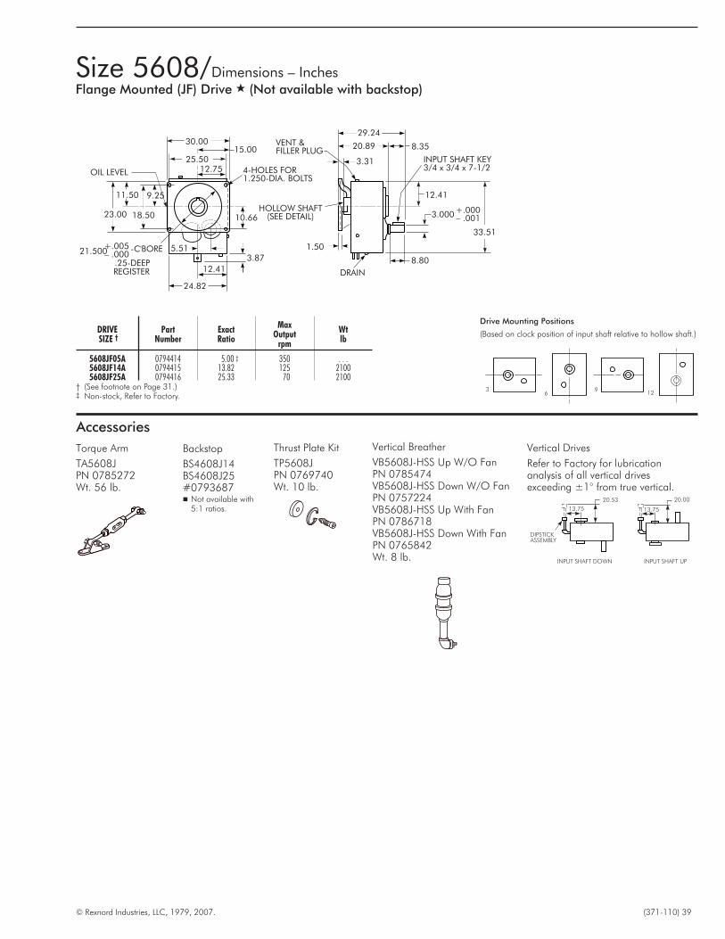
© Rexnord Industries, LLC, 1979, 2007. (371-110) 39
30.00
25.5012.75
15.00
OIL LEVEL
23.00
11.50
18.50
9.25
4-HOLES FOR1.250-DIA. BOLTS
10.66
3.87
12.41
24.82
21.500+.005– .000
-C'BORE
.25-DEEPREGISTER
5.51
VENT &FILLER PLUG
3.31
12.41
INPUT SHAFT KEY3/4 x 3/4 x 7-1/2
33.51
3.000+.000– .001
8.80
DRAIN
1.50
HOLLOW SHAFT(SEE DETAIL)
8.3520.89
29.24
36
912
Drive Mounting Positions
(Based on clock position of input shaft relative to hollow shaft.)
Size 5608/Dimensions – InchesFlange Mounted (JF) Drive � (Not available with backstop)
Accessories
DIPSTICKASSEMBLY
13.75
20.53
INPUT SHAFT DOWN
20.00
13.75
INPUT SHAFT UP
Vertical Drives
Refer to Factory for lubricationanalysis of all vertical drivesexceeding ±1° from true vertical.
Vertical Breather
VB5608J-HSS Up W/O FanPN 0785474VB5608J-HSS Down W/O FanPN 0757224VB5608J-HSS Up With FanPN 0786718VB5608J-HSS Down With FanPN 0765842Wt. 8 lb.
Thrust Plate Kit
TP5608JPN 0769740Wt. 10 lb.
Torque Arm
TA5608JPN 0785272Wt. 56 lb.
DRIVESIZE †
PartNumber
ExactRatio
MaxOutput
rpm
Wtlb
5608JF05A 0794414 5.00 ‡ 350 . . .5608JF14A 0794415 13.82 125 21005608JF25A 0794416 25.33 70 2100
† (See footnote on Page 31.)‡ Non-stock, Refer to Factory.
Backstop
BS4608J14BS4608J25#0793687� Not available with
5:1 ratios.
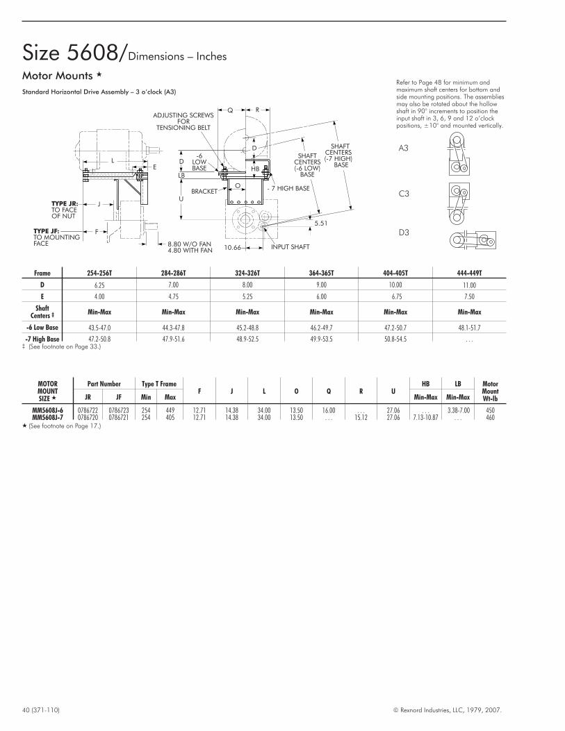
40 (371-110) © Rexnord Industries, LLC, 1979, 2007.
Motor Mounts �
Standard Horizontal Drive Assembly – 3 o’clock (A3)
Refer to Page 48 for minimum andmaximum shaft centers for bottom andside mounting positions. The assembliesmay also be rotated about the hollowshaft in 90° increments to position theinput shaft in 3, 6, 9 and 12 o’clockpositions, ±10° and mounted vertically.
A3
C3
D3
LE
J
F
TYPE JR:TO FACEOF NUT
TYPE JF:TO MOUNTINGFACE
UBRACKET
INPUT SHAFT
- 7 HIGH BASE
HBD
-6LOWBASE
D
ADJUSTING SCREWSFOR
TENSIONING BELT
SHAFTCENTERS(-6 LOW)
BASE
SHAFTCENTERS(-7 HIGH)
BASE
Q R
O
LB
10.668.80 W/O FAN4.80 WITH FAN
5.51
Size 5608/Dimensions – Inches
Frame 254-256T 284-286T 324-326T 364-365T 404-405T 444-449T
D 6.25 7.00 8.00 9.00 10.00 11.00
E 4.00 4.75 5.25 6.00 6.75 7.50
ShaftCenters ‡ Min-Max Min-Max Min-Max Min-Max Min-Max Min-Max
-6 Low Base 43.5-47.0 44.3-47.8 45.2-48.8 46.2-49.7 47.2-50.7 48.1-51.7
-7 High Base 47.2-50.8 47.9-51.6 48.9-52.5 49.9-53.5 50.8-54.5 . . .‡ (See footnote on Page 33.)
MOTORMOUNTSIZE �
Part Number Type T FrameF J L O Q R U
HB LB MotorMountWt-lbJR JF Min Max Min-Max Min-Max
MM5608J-6 0786722 0786723 254 449 12.71 14.38 34.00 13.50 16.00 . . . 27.06 . . . 3.38-7.00 450MM5608J-7 0786720 0786721 254 405 12.71 14.38 34.00 13.50 . . . 15.12 27.06 7.13-10.87 . . . 460
� (See footnote on Page 17.)

© Rexnord Industries, LLC, 1979, 2007. (371-110) 41
Screw Conveyor Options/Dimensions – InchesTROUGH ENDS — Sizes 6 through 24 inches �
E
D
A
F
EB
H
SEALHSG.
2-HOLES FOR-DIA. FASTENERSK
C
B
AB-DIA.HOLE FORDRIVESHAFT
BB-DIA.FASTENER
CB CB
DB
CB
S
T
MV
HOLES FOR-FASTENERZ
HOLES FOR-FASTENERZ
HOLES FOR-FASTENERZ
HOLES FOR-FASTENERZ
R
DWG A DWG B DWG C DWG D
R
S
U
VM
T
M
V
U
T
TS
R R
T
T
T
M
V
U
S
REFER TO VIEWS AT LEFT FOR BALANCE OF REFERENCE LETTERS
SCREWSIZE
DriveShaftDia
Type JSCSize
Range
PartNumber
AboveDwg
AB BB † CB DB EB A B C D E F H K M R S T U VWtlb
6 1.500 5107-5203 0359263 A 2.25 .500 2.000 4.000 1.8 10.1 10.0 8.125 4.5 1.50 1.000 .188 .375 .638 4.438 2.032 4.062 . . . 4.125 7
9 1.500 5107-5203 0359264 B 2.25 .500 2.000 4.000 2.614.0 13.7 9.375 6.1 1.62 1.500 .250 .500 .821 6.250 2.562 3.750 4.125 4.125 182.000 5107-5215 0359265 B 2.25 .625 2.562 5.125 2.6
122.000 5107-5215 0359266 B 2.25 .625 2.562 5.125 2.8
17.4 17.3 12.250 7.8 2.00 1.625 .312 .625 .938 7.938 3.875 4.062 5.188 5.312 312.438 5107-5315 0359272 B 2.56 .625 2.812 5.625 2.83.000 5107-5315 0359273 B 3.12 .750 3.000 6.000 2.8
142.438 5107-5315 0359274 B 2.56 .625 2.812 5.625 2.9
20.1 19.3 16.500 9.3 2.00 1.625 .312 .625 1.107 8.938 3.000 5.938 5.938 5.625 393.000 5107-5315 0359275 B 3.12 .750 3.000 6.000 2.93.000 5407 0359267 B 4.25 .750 4.625 9.250 2.6
163.000 5107-5315 0359276 B 3.12 .750 3.000 6.000 3.3
22.621.7
14.875 10.6 2.50 2.000 .312 .625 1.609 10.000 3.750 6.625 9.625 6.375 513.000 5407 0359268 B 4.25 .750 4.625 9.250 2.7 21.33.438 5407 0359268 B 4.25 .750 4.625 9.250 2.7 21.3
18
3.000 5107-5315 0359277 C 3.12 .750 3.000 6.000 3.3
25.5 24.3 16.000 12.1 2.50 2.000 .375 .625 3.478 11.000 2.938 5.875 5.875 5.938 733.438 5215-5315 0359278 C 3.56 .750 3.375 6.750 3.33.000 5407 0359269 C 4.25 .750 4.625 9.250 2.73.438 5407 0359269 C 4.25 .750 4.625 9.250 2.7
20
3.000 5107-5315 0359279 C 3.12 .750 3.000 6.000 3.8
28.5 26.3 19.250 13.5 2.50 2.250 .375 .750 4.489 12.188 3.344 6.688 6.688 6.250 913.438 5215-5315 0359280 C 3.56 .750 3.375 6.750 3.83.000 5407 0359270 C 4.25 .750 4.625 9.250 3.43.438 5407 0359270 C 4.25 .750 4.625 9.250 3.6
24 3.438 5215-5315 0359281 D 3.56 .750 3.375 6.750 4.1 34.6 30.3 20.000 16.5 2.50 2.500 .375 .750 1.011 14.250 3.312 6.625 6.625 6.125 1263.438 5407 0359271 D 4.25 .750 4.625 9.250 4.1
� (See footnote on Page 17.)† Hex head screws are furnished with Falk™ drive shafts.
SCREW SIZE 6 9 12 14 16 18 20 24
No. 6 8 8 8 8 10 10 12
Dia .375 .375 .500 .500 .625 .625 .625 .625
Description � Part No.
TCB5107-1.438 0766041TCB5115-1.938 0766042TCB5203-2.188 0766043TCB5207-2.438 0766044
TCB5215-2.938 0766045TCB5307-3.438 0766046TCB5315-3.438 0785785TCB5407-3.438 0786823
� Refer to Manual 377-146 for details.� Kit consists of: Bushing, thrust plate, fastener, key, retaining ring, and hardware.
Description Part No.
5107JSC Drive Shafts
DSS5107–1.500 6720054DSS5107–2.000 6720055DSS5107–2.438 6720056DSS5107–3.000 6720057
5115JSC Drive Shafts
DSS5115–1.500 6720058DSS5115–2.000 6720059DSS5115–2.438 6720060DSS5115–3.000 6720061
5203JSC Drive Shafts
DSS5203–1.500 6720062DSS5203–2.000 6720063DSS5203–2.438 6720064DSS5203–3.000 6720065
5207JSC Drive Shafts
DSS5207–1.500 6720066DSS5207–2.000 6720067DSS4207–2.438 6720068DSS5207–3.000DSS5207–3.438
67200696720070
Description Part No.
5215JSC Drive Shafts
DSS5215J–2.000 6720071DSS5215J–2.438 6720072DSS5215J–3.000 6720073DSS5215J–3.438 6720074
5307JSC Drive Shafts
DSS5307J–2.438 6720075DSS5307J–3.000 6720076DSS5307J–3.438 6720077
5315JSC Drive Shafts
DSS5315J–2.438 6720078DSS5315J–3.000 6720079DSS5315J–3.438 6720080
5407JSC Drive Shafts
DSS5407J–3.000 6720081DSS5407J–3.438 6720082
316 Stainless ‡ Steel Drive Shafts � Holes for Z-Fasteners
‡ Check torque & bending capacity of driven shaft and coupling bolt shear againstload. Mechanical properties of stainless steel differ from those of carbon steel.
� Furnished with thrust plate kit and stainless steel trough end-to-sealhousing fasteners.
Taper Conversion Bushing (TCB) Kits �

Sheave Ratios — The table below lists the sheave ratios fornominal gear drive ratios and output speeds when driven by 1750and 1170 rpm motors. If sheave ratios are required for othermotor speeds, or if greater accuracy than ±3% is required for theoutput speed, calculate the sheave ratio with the followingformula, using the exact gear ratios. Check the sheave pitchdiameter against the allowable minimums in Selection Tables 2, 3and 4.
Sheave ratio =Exact Motor Speed
Exact Gear Drive Ratio x Required Output Speed
Drive Ratio Substitution — Selections in Tables 2, 3 and 4 listthe most economical choice of drive size and ratio for a givenoutput speed using 1750 or 1170 rpm motors. Standard driveratios (not drive sizes) can be substituted in recommended drives.See Table 5, Page 13.
V-Belts — Selections can be made from any belt manufacturer’scatalog. If a Falk™ motor mount is used, refer to Pages 16 thru 40for dimensions and shaft centers. When determining belt lengthand minimum center distance, include belt installation allowancein calculations.
42 (371-110) © Rexnord Industries, LLC, 1979, 2007.
Nominal Sheave Ratios and V-Belts
TABLE 12 — Nominal Sheave Ratios �
5:1 Drive 9:1 Drive 14:1 Drive 25:1
DriveOutput
rpm
Motor rpm DriveOutput
rpm
Motor rpm DriveOutput
rpm
Motor rpm DriveOutput
rpm
Motor rpm
1750 1170 1750 1170 1750 1170 1750 1170
372 1.06 . . . 230 1.19 . . . 160 1.28 . . . 80 1.14 . . .362 1.03 . . . 216 1.10 . . . 155 1.23 . . . 76 1.09 . . .356 1.02 1.52 204 1.05 . . . 150 1.20 . . . 73 1.04 . . .350 1.00 1.50 194 1.00 1.51 146 1.16 . . . 70 1.00 . . .338 1.04 1.44 191 1.02 1.47 139 1.11 . . . 69 1.01 . . .
330 1.06 1.41 180 1.08 1.39 135 1.08 . . . 67 1.04 . . .323 1.08 1.38 172 1.13 1.33 130 1.04 . . . 64 1.09 . . .314 1.11 1.34 162 1.20 1.25 125 1.00 1.52 62 1.13 . . .307 1.14 1.31 153 1.27 1.19 120 1.04 1.45 61 1.15 . . .302 1.16 1.29 148 1.31 1.15 118 1.06 1.43 59 1.19 . . .290 1.21 1.24 140 1.39 1.09 113 1.11 1.37 58 1.21 . . .286 1.22 1.22 135 1.44 1.04 109 1.15 1.32 57 1.23 . . .280 1.25 1.20 129 1.50 1.00 106 1.18 1.28 56 1.25 . . .276 1.27 1.18 125 1.55 1.03 100 1.25 1.20 55 1.27 . . .272 1.29 1.16 115 1.69 1.12 98 1.28 1.18 54 1.30 . . .268 1.31 1.15 108 1.80 1.19 95 1.32 1.15 53 1.32 . . .259 1.35 1.11 101 1.92 1.28 92 1.36 1.11 52 1.35 . . .251 1.39 1.07 95 2.04 1.36 89 1.40 1.07 50 1.40 . . .244 1.43 1.04 91 2.13 1.42 86 1.45 1.03 48 1.46 . . .241 1.45 1.03 88 2.20 1.47 83 1.51 1.00 46 1.52 1.00
237 1.48 1.01 85 2.28 1.52 79 1.58 1.05 45 1.56 1.03234 1.50 1.00 84 2.31 1.54 76 1.64 1.09 44 1.59 1.05228 1.54 1.03 80 2.43 1.61 74 1.69 1.12 43 1.63 1.08223 1.57 1.05 77 2.52 1.68 70 1.79 1.19 42 1.67 1.10220 1.59 1.06 74 2.62 1.74 69 1.81 1.20 41 1.71 1.13
216 1.62 1.08 71 2.73 1.82 67 1.87 1.24 40 1.75 1.16210 1.67 1.11 69 2.81 1.87 64 1.95 1.30 39 1.79 1.19206 1.70 1.14 67 2.90 1.93 60 2.08 1.38 38 1.84 1.22204 1.72 1.15 64 3.03 2.02 58 2.16 1.43 37 1.89 1.25201 1.74 1.16 62 3.13 2.08 56 2.23 1.48 36 1.94 1.29
196 1.79 1.19 61 3.18 2.11 54 2.31 1.54 35 2.00 1.32192 1.82 1.22 60 3.23 2.15 52 2.40 1.60 34 2.06 1.36185 1.89 1.26 59 3.29 2.19 50 2.50 1.66 33 2.12 1.40180 1.94 1.30 58 3.34 2.22 48 2.60 1.73 32 2.19 1.45174 2.01 1.34 57 3.40 2.26 46 2.72 1.80 31 2.26 1.49
172 2.03 1.36 56 3.46 2.30 45 2.78 1.84 30 2.33 1.54168 2.08 1.39 55 3.53 2.34 44 2.84 1.89 29 2.41 1.60164 2.13 1.43 54 3.59 2.39 43 2.91 1.93 28 2.50 1.65160 2.19 1.46 53 3.66 2.43 42 2.98 1.98 27 2.59 1.71157 2.23 1.49 52 3.73 2.48 41 3.05 2.02 26 2.69 1.78
151 2.32 1.55 51 3.80 2.53 40 3.13 2.08 25 2.80 1.85146 2.40 1.60 50 3.88 2.58 39 3.21 2.13 24 2.92 1.93141 2.48 1.66 49 3.96 2.63 38 3.29 2.18 23 3.04 2.01133 2.63 1.76 48 4.04 2.69 37 3.38 2.24 22 3.18 2.10126 2.78 1.86 47 4.13 2.74 36 3.47 2.31 21 3.33 2.20
122 2.87 1.92 46 4.22 2.80 35 3.57 2.37 20 3.50 2.32118 2.97 1.98 45 4.31 2.87 34 3.68 2.44 19 3.68 2.44114 3.07 2.05 44 4.41 2.93 33 3.79 2.52 18 3.89 2.57108 3.24 2.17 43 4.51 3.00 32 3.91 2.59 17 4.12 2.72103 3.40 2.27 42 4.62 3.07 31 4.03 2.68 16 4.38 2.89
101 3.47 2.32 41 4.73 3.15 30 4.17 2.77 15 4.67 3.0997 3.61 2.41 40 4.85 3.23 29 4.31 2.86 14 5.00 3.3194 3.72 2.49 39 4.97 3.31 28 4.46 2.96 13 5.38 3.5692 3.80 2.54 38 5.11 3.39 27 4.63 3.07 12 5.83 3.8690 3.89 2.60 37 5.24 3.49 26 4.81 3.19 11 6.36 4.21
36 5.39 3.58 25 5.00 3.32 10 . . . 4.6335 5.54 3.69 24 5.21 3.46 9 . . . 5.1434 5.71 3.79 23 5.43 3.61 8 . . . 5.7933 5.88 3.91 22 5.68 3.77 7 . . . 6.6232 6.06 4.03 21 5.95 3.95 6 . . . 7.731 . . . 4.16 20 6.25 4.15 5 . . . 9.330 . . . 4.30 18 . . . 4.61 4 . . . 11.629 . . . 4.45 16 . . . 5.1928 . . . 4.61 14 . . . 5.9327 . . . 4.78
26 . . . 4.9625 . . . 5.1624 . . . 5.3823 . . . 5.61
� Sheave Ratios in bold face type are speed increasing combinations.

Falk™ V-belt guards offer more than just compliance with OSHArequirements. For one thing, they’re available at a low initial cost.For another, their practical construction makes them extremelyuser-friendly. You can quickly install them using easy-to-mountbrackets. And since these covers are easy-to-remove andlightweight, they simplify field service of belt drives.
V-belt Guards are available in sizes to fit most Quadrive/V-beltcombinations, or be used with other Falk™ drives. They come inan expanded metal cover, with a safety-yellow paint finish. Falk™V-belt guards — easily installed, easily removed.
1) Using Table 13 and known belt drive information, determinewhich guards are suitable.
For overall guard dimensions, refer to Table 19.
2) Determine availability of mounting hardware:
Is guard for use with Falk™ Quadrive?
Will standard Quadrive motor mount be used?
Are standard mounting brackets available (See Table 14)?
Supply guard complete with Option 1: Supply guard only (Table 17)guard mounting brackets. See with loose strapping by Rexnord (Table 18).Table 15 for part numbers of Rexnord will provide 4’ of 12 gage strappingdrive w/o shaft fan. See Table with sheet metal screws. Purchaser must16 for part numbers of drive cut, bend, drill, and mount.with shaft fan.
Option 2; Supply guard on (Table 17).Purchaser is responsible for allmounting.
© Rexnord Industries, LLC, 1979, 2007. (371-110) 43
TABLE 13 — Standard V-Belt Guard Selection –Inches ‡
Selection Parameter
GUARD SIZE †
14E15E,15F
16E,16F
17E,17F
18E19E,19F
20E,20F
21E,21F
Center Distance (Minimum) 21.00 22.00 27.00 29.00 34.00 34.00 32.00 42.50Center Distance (Maximum) 28.00 29.00 34.00 36.00 42.00 42.00 42.00 56.00Maximum Driver Shaft Diameter � 3.50 3.50 3.50 3.50 3.50 3.50 3.50 3.50Maximum Driven Shaft Diameter 2.00 2.25 2.25 2.25 3.00 3.00 3.00 3.00Maximum Driver Sheave Diameter 6.50 8.00 8.00 10.00 10.00 12.00 12.00 14.00Maximum Driven Sheave Diameter 8.00 14.00 14.00 15.00 15.00 20.00 28.00 32.00Maximum Sheave Width 4.00 5.00 5.00 5.00 8.25 8.25 8.25 8.50� Maximum driver is a size 449T NEMA frame.† E = Expanded metal covers (without fans).
F = For drives with shaft driven fans.‡ Table allows for 3.5” of belt take-up adjustment.
YES NO
YES NO
TABLE 14 — Mounting Bracket Availability
GUARDSIZE
DRIVE SIZE
5107 5115 5203 5207 5215 5307 5315 5407 5415 5507 5608
14E OK OK OK OK OK15E OK OK OK OK OK16E OK OK OK OK OK OK17E OK OK OK OK OK
18E OK OK OK19E OK OK OK OK OK OK20E OK OK OK OK21E OK
15F OK16F OK OK OK17F OK OK OK
19F OK OK OK OK OK OK20F OK OK OK OK21F OK
YES NO
Falk™ V-Belt Guards,built for maximum safetyand serviceability.
Guard/Hardware Selection Procedure

44 (371-110) © Rexnord Industries, LLC, 1979, 2007.
TABLE 15 — Part Numbers for Guards Including Quadrive Mounting Brackets – For Drives Without Fan
Expanded Metal Cover
DRIVE SIZEMotor Mount
Position14E 15E 16E 17E 18E 19E 20E 21E
5107
A6, B9, C12, D3
0783719 0783721 . . . . . . . . . . . . . . . . . . . . . . . .5115 0783723 0783725 0783727 . . . . . . . . . . . . . . . . . . . .5203 0783729 0783731 0783733 0783735 . . . . . . . . . . . . . . . .5207 0783737 0783739 0783741 0783743 . . . . . . . . . . . . . . . .5215 0783745 0783747 0783749 0783751 . . . . 0783753 . . . . . . . .5307 . . . . . . . . 0783755 0783757 . . . . 0783759 . . . . . . . .5315 . . . . . . . . 0783761 0783763 . . . . 0783765 . . . . . . . .
5407
A3, B6, C9, D12A9, B12, C3, D6
. . . . . . . . . . . . . . . . 0783768 0783772 0783776 . . . .
A6, B9, C12, D3 . . . . . . . . . . . . . . . . 0783769 0783773 0783777 . . . .
5415
A3, B6, C9, D12A9, B12, C3, D6
. . . . . . . . . . . . . . . . 0783780 0783784 0783788 . . . .
A6, B9, C12, D3 . . . . . . . . . . . . . . . . 0783781 0783785 0783789 . . . .
5507A3, B6, C9, D12 . . . . . . . . . . . . . . . . 0783792 0783796 0783800 . . . .A9, B12, C3, D6 . . . . . . . . . . . . . . . . � � � . . . .A6, B9, C12, D3 . . . . . . . . . . . . . . . . 0783793 0783797 0783801 . . . .
5608
A3, B6, C9, D12. . . . . . . . . . . . . . . . . . . . . . . . 0786865 0786867A9, B12, C3, D6
A6, B9, C12, D3 . . . . . . . . . . . . . . . . . . . . . . . . 0786866 0786868
TABLE 16 — Part Numbers for Guards Including Quadrive Mounting Brackets – For Drives With Fan
Expanded Metal Cover
DRIVE SIZEMotor Mount
Position † 15F 16F 17F 19F 20F 21F
5215A6, B9, C12, D3
0786869 0786870 0786871 0786872 . . . . . . . .5307 . . . . 0786873 0786874 0786875 . . . . . . . .5315 . . . . 0786876 0786877 0786878 . . . . . . . .
5407A3, B6, C9, D12
. . . . . . . . . . . . 0786879 786880 . . . .A9, B12, C3, D6A6, B9, C12, D3
5415A3, B6, C9, D12 . . . . . . . . . . . . 0786881 0786882 . . . .
A9, B12, C3, D6. . . . . . . . . . . . 0786883 0786884 . . . .A6, B9, C12, D3
5507A3, B6, C9, D12 . . . . . . . . . . . . 0786885 0786886 . . . .A9, B12, C3, D6 . . . . . . . . . . . . � � . . . .A6, B9, C12, D3 . . . . . . . . . . . . 0786887 0786888 . . . .
5608A3, B6, C9, D12
. . . . . . . . . . . . . . . . 0786889 0786890A9, B12, C3, D6A6, B9, C12, D3
� Quadrive mounting brackets are not available for these assembly positions.† Refer to Manual 377-820 & 377-822.
Guard Part Numbers
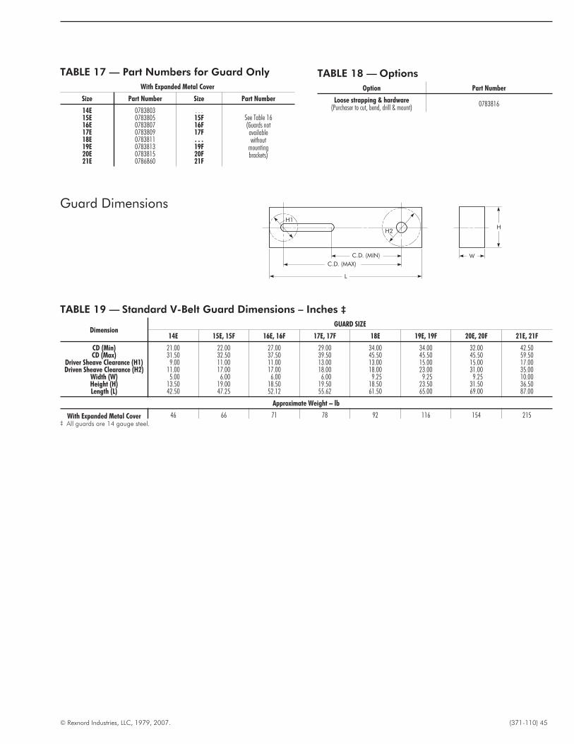
© Rexnord Industries, LLC, 1979, 2007. (371-110) 45
TABLE 17 — Part Numbers for Guard Only
With Expanded Metal Cover
Size Part Number Size Part Number
14E 0783803 . . .See Table 16(Guards notavailablewithout
mountingbrackets)
15E 0783805 15F16E 0783807 16F17E 0783809 17F18E 0783811 . . .19E 0783813 19F20E 0783815 20F21E 0786860 21F
TABLE 18 — Options
Option Part Number
Loose strapping & hardware(Purchaser to cut, bend, drill & mount) 0783816
TABLE 19 — Standard V-Belt Guard Dimensions – Inches ‡
DimensionGUARD SIZE
14E 15E, 15F 16E, 16F 17E, 17F 18E 19E, 19F 20E, 20F 21E, 21F
CD (Min) 21.00 22.00 27.00 29.00 34.00 34.00 32.00 42.50CD (Max) 31.50 32.50 37.50 39.50 45.50 45.50 45.50 59.50
Driver Sheave Clearance (H1) 9.00 11.00 11.00 13.00 13.00 15.00 15.00 17.00Driven Sheave Clearance (H2) 11.00 17.00 17.00 18.00 18.00 23.00 31.00 35.00
Width (W) 5.00 6.00 6.00 6.00 9.25 9.25 9.25 10.00Height (H) 13.50 19.00 18.50 19.50 18.50 23.50 31.50 36.50Length (L) 42.50 47.25 52.12 55.62 61.50 65.00 69.00 87.00
Approximate Weight – lb
With Expanded Metal Cover 46 66 71 78 92 116 154 215‡ All guards are 14 gauge steel.
H1
H2
C.D. (MIN)
C.D. (MAX)
W
L
H
Guard Dimensions
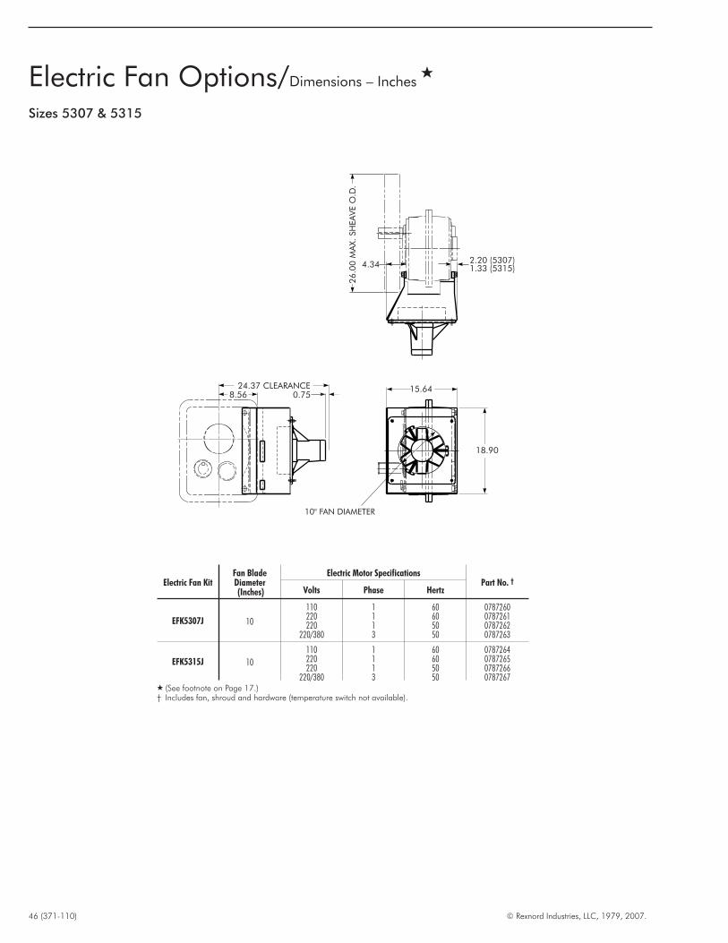
46 (371-110) © Rexnord Industries, LLC, 1979, 2007.
Electric Fan Options/Dimensions – Inches�
Sizes 5307 & 5315
2.20 (5307)1.33 (5315)4.34
26.0
0M
AX.SH
EA
VE
O.D
.
15.64
18.90
0.7524.37 CLEARANCE
8.56
10" FAN DIAMETER
Electric Fan KitFan BladeDiameter(Inches)
Electric Motor SpecificationsPart No. †
Volts Phase Hertz
EFK5307J 10
110 1 60 0787260220 1 60 0787261220 1 50 0787262
220/380 3 50 0787263
EFK5315J 10
110 1 60 0787264220 1 60 0787265220 1 50 0787266
220/380 3 50 0787267� (See footnote on Page 17.)† Includes fan, shroud and hardware (temperature switch not available).
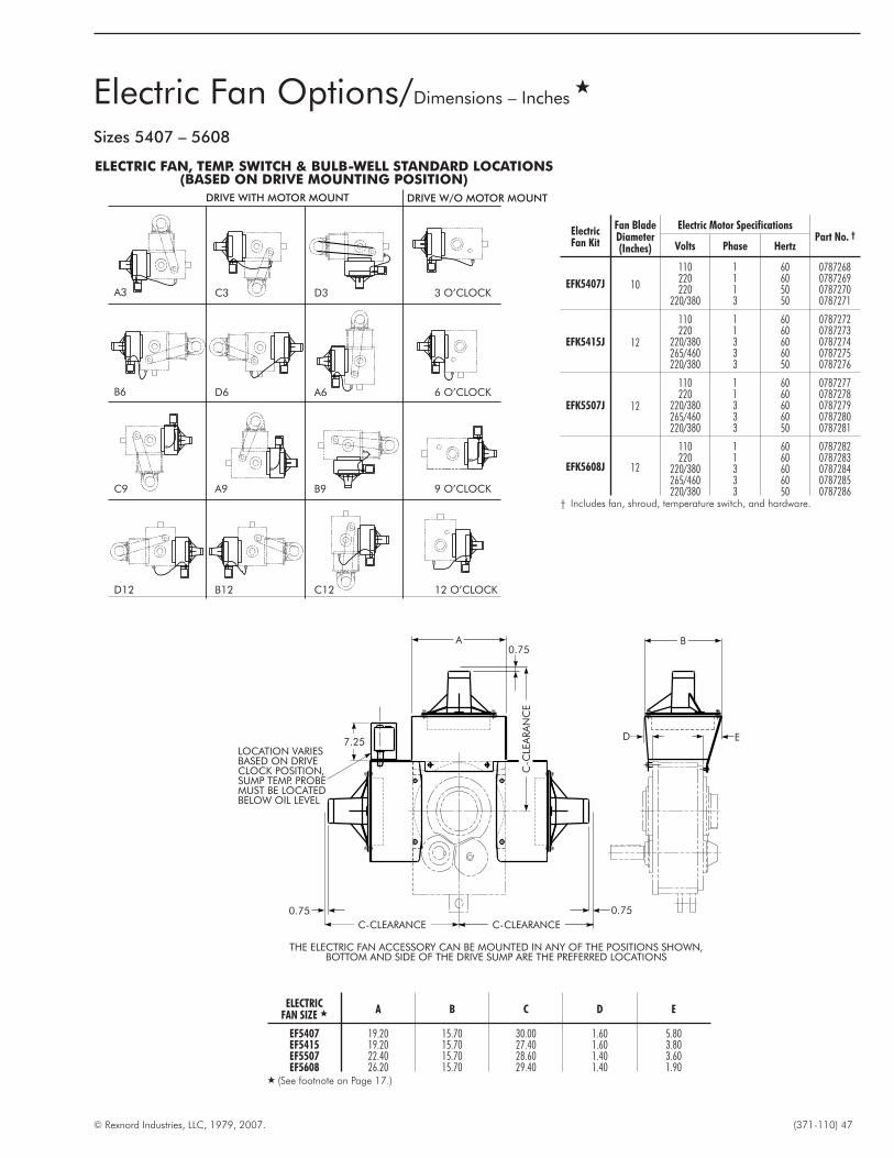
© Rexnord Industries, LLC, 1979, 2007. (371-110) 47
Electric Fan Options/Dimensions – Inches�
ELECTRIC FAN, TEMP. SWITCH & BULB-WELL STANDARD LOCATIONS(BASED ON DRIVE MOUNTING POSITION)
DRIVE WITH MOTOR MOUNT DRIVE W/O MOTOR MOUNT
A3
B6
C9
D12
C3 D3 3 O’CLOCK
D6 A6 6 O’CLOCK
A9 B9 9 O’CLOCK
B12 C12 12 O’CLOCK
Sizes 5407 – 5608
ElectricFan Kit
Fan BladeDiameter(Inches)
Electric Motor SpecificationsPart No. †
Volts Phase Hertz
EFK5407J 10
110 1 60 0787268220 1 60 0787269220 1 50 0787270
220/380 3 50 0787271
EFK5415J 12
110 1 60 0787272220 1 60 0787273
220/380 3 60 0787274265/460 3 60 0787275220/380 3 50 0787276
EFK5507J 12
110 1 60 0787277220 1 60 0787278
220/380 3 60 0787279265/460 3 60 0787280220/380 3 50 0787281
EFK5608J 12
110 1 60 0787282220 1 60 0787283
220/380 3 60 0787284265/460 3 60 0787285220/380 3 50 0787286
† Includes fan, shroud, temperature switch, and hardware.
ELECTRICFAN SIZE � A B C D E
EF5407 19.20 15.70 30.00 1.60 5.80EF5415 19.20 15.70 27.40 1.60 3.80EF5507 22.40 15.70 28.60 1.40 3.60EF5608 26.20 15.70 29.40 1.40 1.90
� (See footnote on Page 17.)
ED
B0.75
A
C-C
LEA
RA
NC
E
C-CLEARANCEC-CLEARANCE
0.750.75
7.25LOCATION VARIESBASED ON DRIVECLOCK POSITION,SUMP TEMP. PROBEMUST BE LOCATEDBELOW OIL LEVEL
THE ELECTRIC FAN ACCESSORY CAN BE MOUNTED IN ANY OF THE POSITIONS SHOWN,BOTTOM AND SIDE OF THE DRIVE SUMP ARE THE PREFERRED LOCATIONS

IntroductionThe following supplements the data published on Pages 30through 40. If shaft centers exceed the published maximum, refercomplete data to Factory for engineering review.
Mounting PositionsThe A3 assembly is the most common horizontal mountingposition. However, the motor mount and drive may be mounted inany of the positions shown at the right. See Table 20 forcenter distance.
48 (371-110) © Rexnord Industries, LLC, 1979, 2007.
Motor Mount Shaft Centers & Motor Frame Sizes
A3
C9
C3
A9
D3
B9
B6
D12
D6
B12
A6
C12
TABLE 20 — Motor-Drive Shaft Centers — Inches
MountingPosition
Motor FrameSize
56T, 143T,145T
182T184T
213T215T
254T256T
284T286T
324T326T
364T365T
404T405T
444T, 445T,447T, 449T
MOTOR MOUNTSIZE
Shaft Centers Min-Max
A3B6C9
D12
MM5407-1 28.0-31.9 28.9-32.9 29.6-33.6MM5407-3 . . . . . . . . . 31.4-35.1 32.1-35.8 33.0-36.8 34.0-37.7 35.0-38.7MM5407-4 . . . . . . . . . 35.1-38.9 35.8-39.6 36.8-40.6 37.8-41.5 38.8-42.5MM5407-5 . . . . . . . . . . . . . . . . . . . . . . . . 37.2-40.7
MM5415-1 29.5-33.2 30.4-34.2 31.2-34.9MM5415-3 . . . . . . . . . 32.7-36.5 33.5-37.3 34.4-38.3 35.4-39.2 36.4-40.2MM5415-4 . . . . . . . . . 36.6-40.3 37.6-41.1 38.3-42.1 39.3-43.0 40.3-44.0MM5415-5 . . . . . . . . . . . . . . . . . . . . . . . . 38.7-42.3
MM5507-1 31.5-35.5 32.5-36.5 33.2-37.2MM5507-3 . . . . . . . . . 34.9-38.7 35.7-39.4 36.6-40.4 37.6-41.4 38.6-42.4MM5507-4 . . . . . . . . . 38.7-42.5 39.5-43.2 40.5-44.2 41.4-45.2 42.4-46.2MM5507-5 . . . . . . . . . . . . . . . . . . . . . . . . 46.1-49.8
MM5608-6 . . . . . . . . . 43.5-47.0 44.3-47.8 45.2-48.8 46.2-49.7 47.2-50.7 48.1-51.7MM5608-7 . . . . . . . . . 47.2-50.8 47.9-51.6 48.9-52.5 49.9-53.5 50.8-54.5
C3D6A9
B12
MM5407-1 22.1-26.0 23.1-27.0 23.8-27.7MM5407-3 . . . . . . . . . 25.4-29.1 26.2-29.8 27.1-30.8 28.1-31.8 29.0-32.7MM5407-4 . . . . . . . . . 29.2-32.9 29.9-33.6 30.8-34.6 31.8-35.5 32.8-36.5MM5407-5 . . . . . . . . . . . . . . . . . . . . . . . . 31.2-34.7
MM5415-1 21.7-25.6 22.7-26.5 23.4-27.0MM5415-3 . . . . . . . . . 24.9-28.6 25.6-29.3 26.6-30.3 27.5-31.3 28.5-32.2MM5415-4 . . . . . . . . . 28.7-32.4 29.4-33.1 30.4-34.1 31.4-35.0 32.3-36.0MM5415-5 . . . . . . . . . . . . . . . . . . . . . . . . 30.8-34.3
MM5507-1 23.3-27.0 24.2-27.9 24.9-28.6MM5507-3 . . . . . . . . . 26.4-29.9 27.1-30.6 28.0-31.6 28.9-32.5 29.9-33.4MM5507-4 . . . . . . . . . 30.0-33.6 30.7-34.3 31.6-35.2 32.5-36.2 33.4-37.1MM5507-5 . . . . . . . . . . . . . . . . . . . . . . . . 37.1-40.7
MM5608-6 . . . . . . . . . 33.0-36.4 33.7-37.1 34.6-38.1 35.6-39.0 36.5-40.0 37.5-41.0MM5608-7 . . . . . . . . . 36.5-40.1 37.2-40.9 38.2-41.8 39.2-42.8 40.1-43.8
D3A6B9C12
MM5407-1 31.8-35.9 32.8-36.9 33.6-37.7MM5407-3 . . . . . . . . . 35.3-39.2 36.1-39.9 37.1-40.9 38.1-41.9 39.1-42.9MM5407-4 . . . . . . . . . 39.2-43.0 40.0-43.8 41.0-44.8 41.9-45.8 42.9-46.7MM5407-5 . . . . . . . . . . . . . . . . . . . . . . . . 41.4-45.0
MM5415-1 32.6-36.6 33.6-37.6 34.3-38.3MM5415-3 . . . . . . . . . 35.9-39.8 36.7-40.5 37.6-41.5 38.6-42.5 39.6-43.5MM5415-4 . . . . . . . . . 39.9-43.7 40.6-44.4 41.6-45.4 42.6-46.4 43.6-47.4MM5415-5 . . . . . . . . . . . . . . . . . . . . . . . . 42.0-45.6
MM5507-1 35.6-39.6 36.5-40.5 37.3-41.3MM5507-3 . . . . . . . . . 39.0-42.8 39.7-43.5 40.7-44.5 41.7-45.5 42.7-46.5MM5507-4 . . . . . . . . . 42.8-46.6 43.5-47.3 44.5-48.3 45.5-49.3 46.5-50.3MM5507-5 . . . . . . . . . . . . . . . . . . . . . . . . 50.3-53.9
MM5608-6 . . . . . . . . . 47.7-51.3 48.4-52.0 49.4-53.0 50.4-54.0 51.4-55.0 52.4-56.0MM5608-7 . . . . . . . . . 51.4-55.1 52.1-55.9 53.1-56.9 54.1-57.9 55.1-58.9

© Rexnord Industries, LLC, 1979, 2007. (371-110) 49
Shim Blocks – Inches
Shim Block Part Number
No. Thickness 56-215T 254-365T 404-449T
X ½ 0.5 0711640 0711645 0759948
X 1 1.0 0711643 0745025 0759949
X 1½ 1.5 0709360 0709361 0709363
SHIM BLOCKS – ALL SIZES — Shim blocks are available (at noextra charge when ordered with the Motor Mount) to increase theshaft centers up to 1½” as shown. Specify thickness required whenordering motor mount. These may be used with either the shortcenter low bases or the long center high bases to assist inmatching the shaft centers to the available V-belt centers. Pleasespecify size shim block required; X½, X1 or X1½.
RT5107-5315J PN 0769406Wt. 8 lb.(Tool with 5 adapters and case)
RT5407-5608J PN 0769407Wt. 10 lb.(Tool with 2 adapters and case)
TA Removal Tool
Thrust Plate Kits for JF Drives UtilizingTA Taper Bushing �
DRIVE SIZE Description � Part No.
5107 TP5107JF 07787735115 TP5115JF 07787745203 TP5203JF 07787755207 TP5207JF 07787765215 TP5215JF 0778777
5307 TP5307JF 07787785315 TP5315JF 07787795407 TP5407JF 07787805415 TP5415JF 07787815507 TP5507JF 07787825608 TP5608JF 0778783
� Refer to Manual 377-142(5107JF thru 5315JF) or 377-144(5407JF thru5608JF).
� Kit consists of: Thrust plate, thrust plate fastener, hollow shaft retaining ring anddrive shaft retaining ring.
Accessories/Options
AGMA Size Comparison
Max Bore(in)
AGMAFalk™
BrowningDodge Sumitomo/
FennerLinkBelt
Dorris4000J 5000J TXT TAII
1 7/16 107 4107J 5107J 107SMT TXT1 TA0107 107 C 107FX 107TR1 15/16 115 4115J 5115J 115SMT TXT2 TA2115 115 D 115FX 115TR2 3/16 203 4203J 5203J 203SMT TXT3 TA3203 203 E 203FX 203TR2 7/16 207 4207J 5207J 207SMT TXT4 TA4207 207 F 207FX 207TR
2 15/16 215 4215J 5215J 215SMT TXT5 TA5215 215 G 215FX 215TR3 7/16 307 4307J 5307J 307SMT TXT6 TA6307 307 H 307FX 307TR3 15/16 315 4315J 5315J 315SMT TXT7 TA7315 315 J 315FX 315TR4 7/16 407 4407J 5407J 407SMT TXT8 TA8407 407 S 407FX 407TR
4 15/16 415 4415J 5415J 415SMT TXT9 TA9415 415 K 415FX 415TR5 7/16 507 4507J 5507J 507SMT TXT10 TA10507 507 L 507D 507TR6 1/2 608 4608J 5608J 608SMT TXT12 TA12608 608 M 608D 608TR
For a competitive interchange, contact your Rexnord District Office or local authorized Rexnord Distributor.

50 (371-110) © Rexnord Industries, LLC, 1979, 2007.
Suggested Drive Arrangement When Falk™ MotorMount Is Not Used
MOTORLOCATION
SHAFTMOUNTEDDRIVE
LOW SPEEDSHAFT ROTATION
TORQUE ARM(TENSION)
MOTORLOCATION
SHAFTMOUNTEDDRIVE
LOW SPEEDSHAFT ROTATION
TORQUE ARM(TENSION)
MOTORLOCATION
SHAFTMOUNTEDDRIVE
TORQUE ARM(TENSION)
LOW SPEEDSHAFT ROTATION
MOTORLOCATION
SHAFTMOUNTEDDRIVE
LOW SPEEDSHAFT ROTATION
TORQUE ARM(COMPRESSION)
PREFERRED
ALTERNATE

© Rexnord Industries, LLC, 1979, 2007. (371-110) 51
THIS PAGE INTENTIONALLY LEFT BLANK

For more than 100 years, the dedicated people of Rexnord
have delivered excellence in quality and service to our
customers around the globe. Rexnord is a trusted name when
it comes to providing skillfully engineered products that
improve productivity and efficiency for industrial applications
worldwide. We are committed to exceeding customer
expectations in every area of our business: product design,
application engineering, operations, and customer service.
Because of our customer focus, we are able to thoroughly
understand the needs of your business and have the resources
available to work closely with you to reduce maintenance
costs, eliminate redundant inventories and prevent equipment
down time.
Rexnord represents the most comprehensive portfolio of power
transmission and conveying components in the world with the
brands you know and trust.
World Class Customer Service
AAUUSSTTRRAALLIIAARexnord Australia Pty. Ltd.
Picton, New South Wales
Phone: 61-2-4677-3811
Fax: 61-2-4677-3812
BBRRAAZZIILLRexnord Correntes Ltda.
Sao Leopoldo - RS
Phone: 55-51-579-8022
Fax: 55-51-579-8029
CCAANNAADDAARexnord Canada Ltd.
Scarborough, Ontario
Phone: 1-416-297-6868
Fax: 1-416-297-6873
CCHHIINNAARexnord China
Shanghai, China
Phone: 86-21-62701942
Fax: 86-21-62701943
EEUURROOPPEERexnord NV/SA
Mechelen, Belgium
Phone: 32-15-.443811
Fax: 32-15-443860
Rexnord Kette GmbH
Betzdorf, Germany
Phone: 49-2741-2840
Fax: 49-2741-284-385
LLAATTIINN AAMMEERRIICCAARexnord International, Inc.
Milwaukee, Wisconsin
Phone: 1-414-643-2366
Fax: 1-414-643-3222
E-mail: [email protected]
MMEEXXIICCOORexnord S.A. de C.V.
Queretaro, Qro.
Phone: 52-442-218.5000
Fax: 52-.442-218-1090
SSIINNGGAAPPOORREERexnord International, Inc.
Singapore City, Singapore
Phone: 65-6338-5622
Fax: 65-6338-5422
UUNNIITTEEDD SSTTAATTEESSCustomer Service
Phone: 1-866-REXNORD
(1-866-739-6673)
Fax: 1-614-675-1898
E-mail: rexnordcs(state)@rexnord.com
Example: [email protected]
AALLLL CCOOUUNNTTRRIIEESS NNOOTT LLIISSTTEEDDRexnord International
Milwaukee, Wisconsin
Phone: 1-414-643-2366
Fax: 1-414-643-3222
E-mail: [email protected]
WORLDWIDE CUSTOMER SERVICE
371-110 02/2007 Delzer Litho Printed in USARexnord Industries, LLC, Gear Group, 3001 West Canal Street, Milwaukee, WI 53208-4200 USA
Phone: 414-342-3131 Fax: 414-937-4359
© 2007 Rexnord Industries LLC
Quadrive, TA Taper, and Rexnord are registered trademarks of Rexnord Industries, LLC. Falk is a
trademark of Rexnord. All rights reserved. Viton is a registered trademark of DuPont.
Recommended