6518/6519
p. 1/18www.burkert.com
3/2-, 5/2- and 5/3-way Solenoid Valves for process pneumatics
The Type 6518 is a servo-assisted 3/2-way
valve and the Type 6519 is a 5/2 or 5/3-way
valve. Together, they form a product line. The
valves can be used individually or in blocks.
The valves work without a continuous air
consumption and are used for the pneumatic
control of double or single-acting actuators. A
solenoid valve Type 6014 is used as a pilot.
The use of high quality materials makes it
possible to use these valves in the open air and
under chemical atmospheres. The product line
contains units with Ex-Approvals and NAMUR
fl ange interface.
Valves with circuit function C, D and H monos-
table are certifi ed acc. IEC 61508 as SIL2.
Type 2508
Cable plug
Type 1078
Timer unit
Type 2511/12
ASI cable plug
Type 6518/6519 can be combined with...
6518/19 standard p. 2
6518/6519 Ex m p. 3
6518/6519 Ex i p. 4
6519 NAMUR standard p. 5
6519 NAMUR Ex m p. 6
6519 NAMUR Ex i p. 7
Manifold assembly with
pneumatic modules MP07
p. 8
Accessories p. 10
Dimensions p. 11
Content
Type 8600
Dosing control
Type 2012
Single-seat
globe valve
Type 2030
Diaphragm valve
• High flow-rate capacity
• Reduced power consumption
• Single or manifold mounting
• Standard-, Ex m and Ex i versions
• Threaded port G 1/4” or NAMUR flange
Type
6518
standard
Type 6519
standard
General technical data
Orifi ce
Type 6518
Type 6519
DN 8 mm
DN 6, 8 and 9 mm
Body material
Type 6518
Type 6519
Polyamide, reinforced
Polyamide (5/2-way), aluminium (5/3-way)
Thread insert material Brass or stainless steel
Seal material
Type 6518
Type 6519
NBR and PUR
NBR, NBR and PUR
Pneumatic connection
Supply ports 1,3,5
Service ports 2 and 4
Threaded port G1/4”, can also be fl anged
Threaded port G1/4” or NAMUR fl ange
Electrical connection Tag connectors acc. to DIN EN 175301-803
(previously DIN 43650) Form A
Operating voltage 24 V DC
24/110/230 V, 50-60 Hz
Voltage tolerance ±10%
Media
Lubricated or non-lubricated compressed air, neutral
gases. Technical vacuum on request
Media temperature -10 to +50°C
Ambient temperature
Standard version
Ex m version
Ex i version
-25 to +55° C
-25 to +50° C
-25 to +55° C
Ambient conditions Open air, chemical atmosphere
Protection class IP 65 with cable plug
Installation As required, preferably with actuator upright
ApprovalsFM-Ex EC Gas Appliances Directive

6518/6519
p. 2/18
Type 6518/6519 standard (with tag connector acc. to DIN EN 175301-803 Form A, without cable plug)
1) Flow rate: QNn value air [l/min]: Measured at +20°C, 6 bar pressure at valve inlet, 1 bar pressure difference
2) Pressure values [bar]: Gauge pressures with respect to the prevailing atmospheric pressure
Ordering chart valves with manual override (without manual override on request)
Manifold assembly see page 8 Accessories see page 10 Dimensions see page 11
Cir
cu
it
fun
cti
on
Ori
fi ce
[mm
]
Se
al
ma
teri
al
bo
dy
Po
rt
co
nn
ecti
on
th
rea
de
d
po
rt
QN
n v
alu
e
air
1) [l
/m
in]
Pre
ssu
re
ran
ge
2)
[ba
r]
We
igh
t [g
]
No
min
al
po
we
r [W
]
Vo
lta
ge
/fr
eq
ue
ncy
[V/H
z]
Ite
m n
o.
Type 6518 standard – thread insert material brass, threaded port 1 and 3 can also be fl anged; without cable plug (see Accessories p. 10)
C
3/2-way valve, servo-assisted, in
de-energized position port 2 exhausted
8.0 NBR and
PUR
(polyamide)
G 1/4 1300 2-8 370 2 024/DC 132 457
024/50-60 132 458
110/50-60 132 459
230/50-60 132 460
D
3/2-way valve, servo-assisted, in de-
energized position port 2 pressurized
8.0 NBR and
PUR
(polyamide)
G 1/4 1300 2-8 370 2 024/DC 132 461
024/50-60 132 462
110/50-60 132 463
230/50-60 132 464
Type 6519 standard – thread insert material brass, threaded port 1, 3 and 5 can also be fl anged; without cable plug (see Accessories p. 10)
H
5/2-way valve, servo-assisted, in de-
energized position port 2 pressurized,
port 4 exhausted
8.0 NBR and
PUR
(polyamide)
G 1/4 1300 2-8 450 2 024/DC 132 465
024/50-60 132 466
110/50-60 132 467
230/50-60 132 468
L
5/3-way valve, servo-assisted, in middle
position all ports locked
9.0 NBR
(aluminium)
G 1/4 1300 3-10 720 2 024/DC 132 469
024/50-60 132 470
110/50-60 132 471
230/50-60 132 472
N
5/3-way valve, servo-assisted, in middle
position ports 2 and 4 exhausted
9.0 NBR
(aluminium)
G 1/4 1300 3-10 720 2 024/DC 132 473
024/50-60 132 474
110/50-60 132 475
230/50-60 132 476
2
312
110
1
2
310
12
15 3
4 2
14 12
15 3
4 2
14 12
1) Measured at valve outlet at 6 bar and +20°C acc. to ISO 12238.
Opening: Pressure rise 0 to 90%
Closing: Pressure drop 100 to 10%
Technical data
Orifi ce DN 8.0 and 9.0 mm
Body materials
Type 6518
Pilot valve and main
valve Type 6519
Pilot valve
Main valve
Polyamide, reinforced
Polyamide
5/2-way; polyamide, 5/3-way; aluminium
Thread insert material Brass (stainless steel on request)
Seal materials NBR, NBR and PUR
Pneumatic connection
Supply ports 1,3,5
Service ports 2 and 4
Threaded port G 1/4, can also be fl anged
Threaded port G 1/4 (on request NPT 1/4)
Electrical connection
Tag connector acc. to DIN EN 175301-803 Form A
(previously DIN 43650)
Protection class IP65 with cable plug
Operating voltage 24 V/DC, 24/110/230 V, 50-60 Hz
Voltage tolerance ±10%
Power consumption coil 2 W (100% continuous rating)
Ambient temperature -25 to +55°C
Media
on request
Lubricated or non-lubricated compressed air, neutral gases
Technical vacuum
Environmental
conditions
Open air, chemical atmosphere
Type 6518
standard Type 6519
standard
Type 6518 and the Type 6519 together form a product
line. Both types can be mounted on a pneumatic module.
The valve width of 32 mm allows high fl ow rates.
A solenoid valve Type 6014 is used as a pilot.
The valves can be used individually or in blocks.
Power consumption
Inrush Hold (hot coil)
AC [VA] AC [VA/W] DC [W]
11 6/2 2
Response times 1)
Opening
Closing
20 [ms]
40 [ms]
4(B) 2(A)
5(S) 3(R)1(P)
1412

6518/6519
p. 3/18
Type 6518/6519 Ex m (with moulded cable, 3 m long, terminal box on request)
Technical data
Orifi ce DN 8.0 and 9.0 mm
Body materials
Type 6518
Pilot valve and main
valve Type 6519
Pilot valve
Main valve
Polyamide, reinforced
Polyamide
5/2-way; polyamide, 5/3-way; aluminium
Thread insert material Brass (stainless steel on request)
Seal materials NBR, NBR and PUR
Pneumatic connection
Supply ports 1,3,5
Service ports 2 and 4
Threaded port G 1/4, can also be fl anged
Threaded port G 1/4 (on request NPT 1/4)
Electrical connection
Moulded cable, 3 m (non-detachable),
Terminal box on request
Protection class IP65
Approval II 2G Ex m II T 5 PTB 00 ATEX 2129X
II 2DIP 65T 100°C
Operating voltage 24/110/230 V/UC
Voltage tolerance ±10%
Power consumption coil 3 W (100% continuous rating)
Ambient temperature -25 to +50°C
Media
on request
Lubricated or non-lubricated compressed air, neutral gases
technical vacuum
Environmental conditions Open air, chemical atmosphere
For use in zone 1, 2, 21 and 22
Cir
cu
it
fun
cti
on
Ori
fi ce
[mm
]
Se
al
ma
teri
al
bo
dy
Po
rt
co
nn
ecti
on
th
rea
de
d
po
rt [
inch
]
QN
n
va
lue
air
1) [l
/m
in]
Pre
ssu
re
ran
ge
2)
[ba
r]
We
igh
t [g
]
No
min
al
po
we
r [W
]
Vo
lta
ge
/fr
eq
ue
ncy
[V/H
z]
Ite
m n
o.
Type 6518 Ex m – thread insert material brass, threaded port 1 and 3 can also be fl anged; with moulded cable, 3 m long 3)
C
3/2-way valve, servo-assisted, in
de-energized position port 2 exhausted
8.0 NBR
and
PUR
(polyamide)
G 1/4 1300 2-8 600 3 024/UC 134 716
110/UC 134 717
230/UC 134 718
D
3/2-way valve, servo-assisted, in de-
energized position port 2 pressurized
8.0 NBR
and
PUR
(polyamide)
G 1/4 1300 2-8 600 3 024/UC 134 719
110/UC 134 720
230/UC 134 721
Type 6519 Ex m – thread insert material brass, threaded port 1, 3 and 5 can also be fl anged; with moulded cable, 3 m long 4)
H
5/2-way valve, servo-assisted, in de-
energized position port 2 pressurized,
port 4 exhausted
8.0 NBR
and
PUR
(polyamide)
G 1/4 1300 2-8 700 3 024/UC 134 722
110/UC 134 723
230/UC 134 724
L
5/3-way valve, servo-assisted, in middle
position all ports locked
9.0 NBR
(aluminium)
G 1/4 1300 3-10 1,100 3 024/UC 134 725
110/UC 134 726
230/UC 134 727
N
5/3-way valve, servo-assisted, in middle
position ports 2 and 4 exhausted
9.0 NBR
(aluminium)
G 1/4 1300 3-10 1,100 3 024/UC 134 728
110/UC 134 729
230/UC 134 730
1) Flow rate: QNn value air [l/min]: Measured at +20°C, 6 bar pressure at valve inlet, 1 bar pressure difference 2) Pressure values [bar]: Gauge pressures with respect to the prevailing atmospheric pressure
3) Versions with terminal box on request 4) Circuit function H (5/2-way) as impulse version on request
Ordering chart valves with manual override (without manual override on request)
1) Measured at valve outlet at 6 bar and +20°C acc. to ISO 12238.
Opening: Pressure rise 0 to 90%,
Closing: Pressure drop 100 to 10%
The approval Ex m is achieved by the mounting of an
approved push-over coil. The cable connection and the
cable are non-detachable and sealed together with the
valve. The valves can be used individually or in blocks.
2
312
110
1
2
310
12
15 3
4 2
14 12
15 3
4 2
14 12
Response times 1)
Opening
Closing
20 [ms]
50 [ms]
Manifold assembly see page 8 Accessories see page 10 Dimensions see page 13
Type 6519 Ex m
Type 6518 Ex m
4(B) 2(A)
5(S) 3(R)1(P)
1412

6518/6519
p. 4/18
Type 6518/6519 Ex i (with tag connector acc. to DIN EN 175301-803 Form A, without cable plug)
Technical data
Orifi ce DN 8.0 mm
Body materials
Pilot valve
Main valve
Stainless steel 1.4305 or brass
Polyamide, glass-fi bre reinforced
Thread insert material Stainless steel or brass, nickel-plated
Seal materials FPM, NBR and PUR
Pneumatic connection
Supply ports 1,3,5
Service ports 2 and 4
Threaded port G 1/4”
Threaded port G 1/4”
Electrical connection
Tag connector acc. to DIN EN 175301-803 Form A
(previously DIN 43650) for cable plug Type 2508 (not
included, see accessories). Ensure correct polarity!
Protection class IP65 with cable plug
Ambient temperature -25 to +55°C
Media Lubricated or non-lubricated compressed air,
instrument air, nitrogen
Environmental conditions Open air, chemical atmosphere
For use in zone 1, 2, 21 and 22
Cir
cu
it
fun
cti
on
Ori
fi ce
[mm
]
Se
al
ma
teri
al
bo
dy
Po
rt
co
nn
ecti
on
th
rea
de
d
po
rt [
inch
]
QN
n v
alu
e
air
1)
[l/m
in]
Pre
ssu
re
ran
ge
2)
[ba
r]
We
igh
t [g
]
Bo
dy
ma
teri
al
pil
ot
va
lve
Pil
ot
air
th
rea
d
inse
rt
ma
teri
al
Ite
m n
o.
Type 6518 Ex i without cable plug (see accessories page10)
C
3/2-way valve, servo-assisted, in de-
energized position port 2 exhausted
8.0
NBR
and
PUR
(polyamide)
G 1/4 1300 2-8 580
St. st.
1.4305
St. st. 145 111
brass, nickel
plated144 486
brassbrass, nickel
plated147 253
Type 6519 Ex i without cable plug (see accessories page10)
H
5/2-way valve, servo-assisted,
in de-energized position port 2
pressurized, port 4 exhausted
8.0
NBR
and
PUR
(polyamide)
G 1/4 1300 2-8 670
St. st.
1.4305
St. st. 144 484
brass, nickel
plated144 485
brassbrass, nickel
plated147 252
1) Flow rate: QNn value air [l/min]: Measured at +20°C, 6 bar pressure at valve inlet, 1 bar pressure difference
2) Pressure values [bar]: Gauge pressures with respect to the prevailing atmospheric pressure
Ordering chart valves without manual override (with manual override and high-impedance coil on request)
NoteThese units may only be used in explosive atmospheres in
the manner approved by the Federal Institute of Physics and
Technology (PTB), i.e., the permissible maximum electrical
values must be complied with. Suitable barriers and isolating
modules are available for this.
Electrical data - Coil AC10 Ex i
Approval II 2G Ex ia IIC T6 PTB 01 ATEX 2101
II 2D Ex ia D21 T 80°C
Functional values for the
valve switching function1) at +20°C at +55°C
Minimum switching current
Nominal resistance of the coil
Minimum terminal voltage
29 mA
310 Ω
9.0 V
29 mA
360 Ω
10.4 V
Permissible maximum
values acc. to certifi cate
of conformity
Ui
Ii
Pi
35 V
0.9 A
1.1 W
The intrinsically-safe Type 6518 Ex i and 6519 Ex i valves
consist of an intrinsically-safe pilot control and a pneumatic
amplifi er. The diaphragm-controlled valve seats work with
very low friction, ensuring reliable switching of the valve,
even after long shutdown periods.
1) Measured at valve outlet at 6 bar and +20°C acc. to ISO 12238.
Opening: Pressure rise 0 to 90%,
Closing: Pressure drop 100 to 10%
The valve is intended for operation on 24 VDC outputs via the
intermediate switching of a corresponding intrinsically-safe
operating resource (isolating module or barrier).
If required, request the “Recommended Barrier and Isolating
Module” data sheet. 1) With high-impedance coil on request
WW C ohne Handnotbetätigung
2
312
110
Barrier/
isolating
component
PLC
Response times 1)
Opening
Closing
75 [ms]
115 [ms]
Accessories see page 10 Dimensions see page 14
4(B) 2(A)
5(S) 3(R)1(P)
1412
Type 6518 Ex i
Type 6519 Ex i

6518/6519
p. 5/18
Type 6519 NAMUR standard (with tag connector acc. to DIN EN 175301-803 Form A, without cable plug)
Technical data
Orifi ce DN 6.0 mm
Body materials
Pilot valve and main valve Polyamide (PA)
Thread insert material Brass, nickel-plated or stainless steel
Seal material NBR and PUR
Pneumatic connection
Supply ports 1,3,5
Service ports 2 and 4
Threaded port G 1/4”
NAMUR fl ange
Electrical connection
Tag connector acc. to DIN EN 175301-803 Form A
(previously DIN 43650)
Protection class IP65 with cable plug
Operating voltage 24/110/230 V/UC (direct or universal current)
Voltage tolerance ±10%
Duty cycle 100 % continuous rating
Ambient temperature -25 to +55°C
Media Compressed air, nitrogen, instrument air
Environmental conditions Slightly aggressive, also open air
Cir
cu
it
fun
cti
on
Ori
fi ce
[mm
]
Se
al
ma
teri
al
bo
dy
Th
rea
d
inse
rt
ma
teri
al
1)
Po
rt
co
nn
ecti
on
th
rea
de
d
po
rt [
inch
]
QN
n v
alu
e
air
2)
[l/m
in]
Pre
ssu
re
ran
ge
3)
[ba
r]
We
igh
t [g
]
Po
we
r co
nsu
mpti
on
[W]
Vo
lta
ge
/fr
eq
ue
ncy
[V/H
z]
Ite
m n
o.
C
3/2-way valve with exhaust recycling,
in de-energized position port 2 fed
back internally
or
6.0
NBR
and
PUR
stainless
steelG 1/4 900 2-8 460 2
024/DC 131 425
024/50-60 131 426
110/50-60 131 427
230/50-60 131 428
H
5/2-way valve, servo-assisted, in de-
energized position pressure port 1 con-
nected to port 2, output 4 exhausted
6.0
NBR
and
PUR
brass,
nickel-
plated
G 1/4 900 2-8 460 2
024/DC 131 421
024/50-60 131 422
110/50-60 131 423
230/50-60 131 424
1) If the connectors are from stainless steel, the mounting screws will also be from stainless steel
2) Flow rate: QNn value air [l/min]: Measured at +20°C, 6 bar pressure at valve inlet, 1 bar pressure difference
3) Pressure values [bar]: Gauge pressures with respect to the prevailing atmospheric pressure
Ordering chart valves with manual override (without manual override on request)
without cable plug (see accessories page10)
The valve bodies of Type 6519 NAMUR are identical
with the Ex m variants. The difference is in the coils,
which are laid out and approved in different ways. By
changing the coil on the valve body, it is possible to
easily convert from Non-Ex operation to Ex operation
(or vice versa). The coils are designed to be push-over
and can be locked in 4 x 90° displaced positions and
be positioned any where in-between.
All valves can be operated in circuit function C as well as in circuit function H. By replacing the adapter
plate that comes with the valves, the change between the two circuit functions can be set up.
12
4 2
513
Power consumption
Inrush Hold (hot coil)
AC [VA] AC [VA/W] DC [W]
11 6/2 2
1) Measured at valve outlet at 6 bar and +20°C acc. to ISO 12238.
Opening: Pressure rise 0 to 90%,
Closing: Pressure drop 100 to 10%
Response times 1)
Opening
Closing
20 [ms]
40 [ms]
Accessories see page 10 Dimensions see page 15
4(B) 2(A)
5(S) 3(R)1(P)
1412
Type 6519 NAMUR
Standard

6518/6519
p. 6/18
Type 6519 NAMUR Ex m
Type 6519 NAMUR Ex m NAMUR valve for process plants
switches reliably, even when fully restricted. The valve made
out of premium polyamide can be operated either as a 5/2
or a 3/2-way version through different mounting plates. The
solenoid valve Type 6014 with a coil approved for use in
hazardous areas is connected as a pilot. The NAMUR fl ange
interface allows easy assembly on different pneumatic ac-
tuators on the spot.
The valve bodies are identical with the Type 6519 NAMUR
standard version. The difference between the valves is in
the coils, which are laid out and approved in different ways.
By changing the coil on the valve body, it is possible to eas-
ily convert from Non-Ex operation to Ex operation (or vice
versa). Coil versions with moulded cable are designed to be
push-over and can be locked in 4 x 90° displaced positions
and be positioned any where in-between.
Type 6519 NAMUR Ex m (with moulded cable) or Ex me (with terminal box)
Technical data
Orifi ce DN 6.0
Body materials
Pilot valve and main valve Polyamide (PA)
Thread insert material Brass, nickel-plated or stainless steel
Seal material NBR and PUR
Pneumatic connection
Supply ports 1,3,5
Service ports 2 and 4
Threaded port G 1/4”
NAMUR fl ange
Protection class IP65
Approval II 2G Ex m II T 5 PTB 00 ATEX 2129X
II 2DIP 65T 100°C
II 2G Ex e mb IIC T5 Gb PTB 02 ATEX 2094 X
(for terminal box)
EX e mb IIC T5 IEC Ex PTB 09.0064X
(for terminal box)
Operating voltage 24/110/230 V/UC (universal current)
Voltage tolerance ±10%
Duty cycle 100% continuous rating
Ambient temperature -25 to +55°C
-25 to +50°C (for terminal box 4)
Media Lubricated or non-lubricated compressed air, nitrogen,
instrument air
Environmental
conditions
Slightly aggressive, also open air
Cir
cu
it
fun
cti
on
Ori
fi ce
[m
m]
Se
al
ma
teri
al
bo
dy
Th
rea
d i
nse
rt
ma
teri
al
1)
Po
rt
co
nn
ecti
on
th
rea
de
d
po
rt [
inch
]
QN
n v
alu
e
air
2)
[l/m
in]
Pre
ssu
re
ran
ge
3) [b
ar]
We
igh
t [g
]
Po
we
r co
nsu
mp
tio
n
[W]
Vo
lta
ge
/fr
eq
ue
ncy
[V/H
z]
Ite
m n
o.
Version acc. to Ex m, with 3 m long moulded cable
C
3/2-way valve, with exhaust air
return, in de-energized position
port 2 exhausted internally
or
6.0
NBR
and
PUR
stainless
steelG 1/4 900 2-8 650 3
024/UC 131 631
110/UC 131 632
230/UC 131 633
brass,
nickel-
plated
G 1/4 900 2-8 650 3
024/UC 131 627
110/UC 131 628
230/UC 131 629
H
5/2-way valve, servo-assisted,
in de-energized position pressure
port 1 connected to port 2, port 4
exhausted
Version acc. to Ex me, with terminal box without fuse (see Accessories p. 10)
6.0
NBR
and
PUR
stainless
steelG 1/4 900 2-8 690 54)
024/UC 139 067
230/UC 139 069
brass,
nickel-
plated
G 1/4 900 2-8 690 54)
024/UC 427 978
110/UC 139 065
230/UC 139 066
1) If the connectors are from stainless steel, the mounting screws will also be from stainless steel 2) Flow rate: QNn value air [l/min]: Measured at +20°C, 6 bar pressure at valve inlet, 1 bar pressure difference 3) Pressure values [bar]: Gauge pressures with respect to the prevailing atmospheric pressure. 4) 5W T5 � Tu 50°C, 7W T4 � Tu 55°C
Ordering chart valves with manual override (without manual override on request)
12
4 2
513
All valves can be operated in circuit function C as well as in circuit function H. By replacing the adapter plate that comes with the valves, the change between the
two circuit functions can be set up.
1) Measured at valve outlet at 6 bar and +20°C acc. to ISO 12238.
Opening: Pressure rise 0 to 90%,
Closing: Pressure drop 100 to 10%
Response times 1)
Opening
Closing
20 [ms]
40 [ms]
Accessories see page 10 Dimensions see page 15
4(B) 2(A)
5(S) 3(R)1(P)
1412
6518/6519
p. 7/18
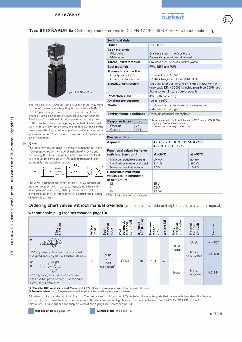
Type 6519 NAMUR Ex i (with tag connector acc. to DIN EN 175301-803 Form A, without cable plug)
Technical data
Orifi ce DN 6.0 mm
Body materials
Pilot valve
Main valve
Stainless steel 1.4305 or brass
Polyamide, glass-fi bre reinforced
Thread insert material Stainless steel or brass, nickel-plated
Seal materials FPM, NBR and PUR
Pneumatic connection
Supply ports 1,3,5
Service ports 2 and 4
Threaded port G 1/4”
NAMUR fl ange acc. to VDI/VDE 3845
Electrical connection
Tag connector acc. to DIN EN 175301-803 Form A
(previously DIN 43650) for cable plug Type 2508 (see
Accessories). Ensure correct polarity!
Protection class IP65 with cable plug
Ambient temperature -25 to +55°C
Media Lubricated or non-lubricated compressed air,
instrument air, nitrogen
Environmental conditions Open air, chemical atmosphere
Cir
cu
it
fun
cti
on
Ori
fi ce
[mm
]
Se
al
ma
teri
al
bo
dy
Po
rt
co
nn
ecti
on
th
rea
de
d
po
rt [
inch
]
QN
n v
alu
e
air
1) [l
/m
in]
Pre
ssu
re
ran
ge
2)
[ba
r]
We
igh
t [g
]
Bo
dy
ma
teri
al
pil
ot
va
lve
Ma
teri
al
for
co
ntr
ol
air
bu
sh
Ite
m n
o.
C
3/2-way valve, with exhaust air return, in de-
energized position port 2 exhausted internally
6.0
NBR
and
PUR
(polyamide)
G 1/4 900 2-8 670
St. st.
1.4305
St. st. 144 482
brass,
nickel-plated144 483
brassbrass,
nickel-plated147 244
or
H
5/2-way valve, servo-assisted, in de-ener-
gized position pressure port 1 connected to
port 2, port 4 exhausted
1) Flow rate: QNn value air [l/min]: Measured at +20°C, 6 bar pressure at valve inlet, 1 bar pressure difference
2) Pressure values [bar]: Gauge pressures with respect to the prevailing atmospheric pressure.
Ordering chart valves without manual override (with manual override and high-impedance coil on request)
without cable plug (see accessories page10)
Electrical data
Approval II 2G Ex ia IIC T6 PTB 01 ATEX 2101
II 2D Ex ia D21 T 80°C
Functional values for valve
switching function 1) at +20°C at +55°C
Minimum switching current
Nominal resistance of the coil
Minimum terminal voltage
29 mA
310 Ω
9.0 V
29 mA
360 Ω
10.4 V
Permissible maximum
values acc. to certifi cate
of conformity
Ui
Ii
Pi
35 V
0.9 A
1.1 W
The Type 6519 NAMUR Ex i valve is used for the pneumatic
control of double or single-acting actuators with a NAMUR
adapter plate fl ange. The circuit function can easily be
changed using an adapter plate. In the 3/2-way function,
feedback of the exhaust air takes place in the spring area
of the armature drive. The diaphragm-controlled valve seats
work with very low friction, ensuring reliable switching of the
valve even after long shutdown periods and at ambient tem-
peratures below 0 °C. The valves work without a continuous
air consumption.
All valves can be operated in circuit function C as well as in circuit function H. By replacing the adapter plate that comes with the valves, the change
between the two circuit functions can be set up. All valves have mounting plates and tag connectors acc. to DIN EN 175301-803 Form A
(previously DIN 43650) and are supplied without cable plug (see Accessories p. 10)
NoteThe units may only be used in explosive atmospheres in the
manner approved by the Federal Institute of Physics and
Technology (PTB), i.e., the permissible maximum electrical
values must be complied with. Suitable barriers and isolat-
ing modules are available for this.
The valve is intended for operation on 24 VDC outputs via
the intermediate switching of a corresponding intrinsically-
safe operating resource (isolating module or barrier).
If required, request the “Recommended Barrier and Isolating
Module” data sheet.1) With high-impedance coil on request
12
4 2
513
Barrier/
isolating
component
PLC
1) Measured at valve outlet at 6 bar and +20°C acc. to ISO 12238.
Opening: Pressure rise 0 to 90%,
Closing: Pressure drop 100 to 10%
Response times 1) [ms]
Opening
Closing
75
115
Accessories see page 10 Dimensions see page 16
Type 6519 NAMUR Ex i
4(B) 2(A)
5(S) 3(R)1(P)
1412

6518/6519
p. 8/18
Pneumatic modules Type MP07
Connector module,
left
Supply ports
3(R)
1(P)
5(S)
Pneumatic basic
module, 3 valves
Covering plate for 3/2-
way valves (to cover up
unused ports)
Pneumatic intermediate supply module: supply channel pushed
through for additional pressure supply
or
Connector module, right: supply channel closed off, thereby several
operational pressures possible in a single block
Pneumatic
basic module,
2 valvesConnector module,
right
Single modules or pre-mounted blocks are available.
Ordering chart for Type MP07 pneumatic modules
Ve
rsio
n
Ite
m n
o.
Connector module right G1/2 635 331
Intermediate supply module 637 505
Pneumatic basic module, 2 valves universal (for 3/2-, 5/2- and 5/3-way) 635 319
Pneumatic basic module, 3 valves universal (for 3/2-, 5/2- and 5/3-way) 635 343
Connector module left G1/2 635 324
Covering plate for 5/2- and 5/3-way (to cover unused valve positions) 635 335
Covering plate for 3/2-way (to cover unused connections) 635 337
Note when ordering complete valve blocks:
Please list the modules in the block assembly from right to left, as shown in the ordering example.
Valves with NAMUR Flange. Ex i coil or Ex versions with terminal boxes are not suitable for block mounting.
No
.
Un
it
Ite
m n
o.
1 Connector module right, G1/2 635 331
1 Pneumatic basic module, 2 valves 635 319
1 Pneumatic basic module, 3 valves 635 343
1 Connector module left, G1/2 635 324
5 Valves 132 457
Example of a complete valve block
Ordering example for Type 6518 with Type MP07

6518/6519
p. 9/18
Manifold assembly either wall-mounted or standard mounting DIN rail 50022 or 50023
59 + (n x 33)
5/2
5/3, 5/3 - Impulse
153542
55
3
1
5
G 1/8
NPT 1/8
n x 33
87 + (n x 33)110 + (n x 33)
G 1/4
NPT 1/4
33
55
G 1/2
NPT 1/2
5
1
3
11
51
08
10
2.5
57
.54
81
0
24
58
921
20
18
2
101.565
68
4652
90
24
9
12
4.8
10
08
2ø
5.5
Dimensions Type MP07 pneumatic modules [mm]
Valve assembly on pneumatic modules Type MP05 using the supplied M4 screws
n=no. of valves, maximal 12
Type MP07 pneumatic modules, continued

6518/6519
p. 10/18
Accessories
Circuitry Voltage Item no.
For standard version 6518/19
Fixing screw in steel (galvanised and chrome-plated)
without circuitry 0 - 250 V 008 376
with LED 12 - 24 V 008 360
with LED and varistor 12 - 24 V 008 367
with LED and varistor 200 - 240 V 008 369
For Ex i version 6519
Fixing screw in stainless steel 1.4404 and blue compression gland nut
without circuitry 0 - 250 V 438 574
for further versions see datasheet 2508
Dimensions Type 2508 [mm]
18
18
Cable plug Type 2508 acc. to DIN EN 175301-803 Form AThe delivery of a cable plug includes the fl at seal and the fi xing screw. For other cable plug
versions acc. to DIN EN 175301-803 Form A (previously DIN 43650) with
integrated circuitry, see datasheet Type 2508.
Accessory Feature Item no.
Cap nutCap nut in stainless steel for
additional protection of the exhaust air
channel from the penetration of damp
649 554
Blanking plug G 1/8” 780 141
G 1/4” 780 142
G 1/2” 780 144
Silencer G 1/8” 005 305
G 1/4” 005 064
G 1/2” 005 062
Labelling plate 64 pieces 635 416
Ordering chart further Accessories
Flat seal
Fixing screw
46
M328
27
,51
,5
18
Voltage [V] Max. current [mA] Item no.
24 V 315 mA 153 733
110 V 50 mA 153 716
230 V 32 mA 153 715
Semi-delay fuse for 6519 NAMUR Ex m
Ordering chart cable plug Type 2508
6518/6519
p. 11/18
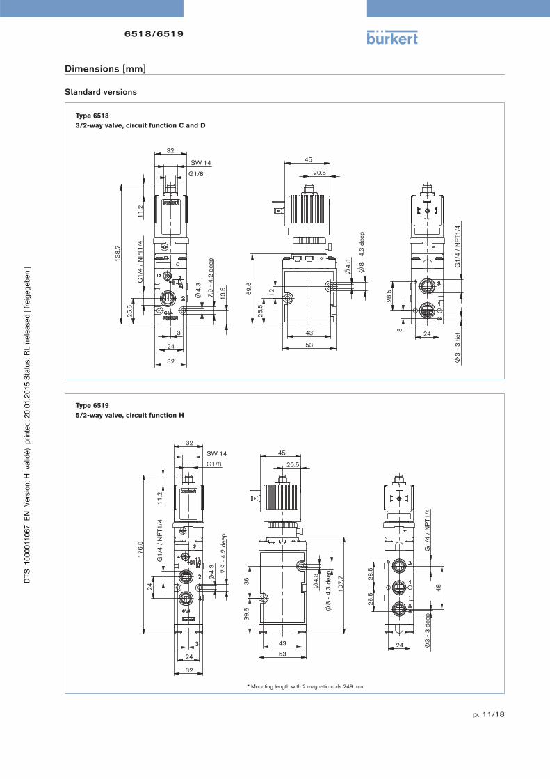
Type 6519
5/2-way valve, circuit function H
Standard versions
* Mounting length with 2 magnetic coils 249 mm
Dimensions [mm]
Type 6518
3/2-way valve, circuit function C and D
25.
5
12
69.
6
4.
3
8
- 4.
3 de
ep
43
53
45
20.5
4.
3
7.9
- 4
.2 d
eep
13.
5
24
32
G1/
4 /
NP
T1/4
25.
5
138
.7
11.
2
G1/8
SW 14
32
3
3
- 3
tief
G1/
4 /
NP
T1/4
8
28.
5
24
43
53
39.
6 3
6
4.
3
8
- 4.
3 de
ep
107
.7
45
20.5
24
32
4.
3
7.9
- 4
.2 d
eep
G1/
4 /
NP
T1/4
24
G1/8
SW 14
176
.8
32
11.
2
3
28.
5 2
6.5
24
48
G1/
4 /
NP
T1/4
3 -
3 de
ep

6518/6519
p. 12/18
Type 6519
5/3-way valve, circuit function L and N
Standard versions
Dimensions [mm]
112
50
36
44
43
45
4.
3
20.5
24
G1/
4 /
NP
T1/4
4.
5
11
- 3
dee
p
70
26
32
250
.2
G1/8
11.
2
SW 14
32
28.
5
3
- 3
deep
26.
5
G1/
4/
NP
T1/4
24
6518/6519
p. 13/18
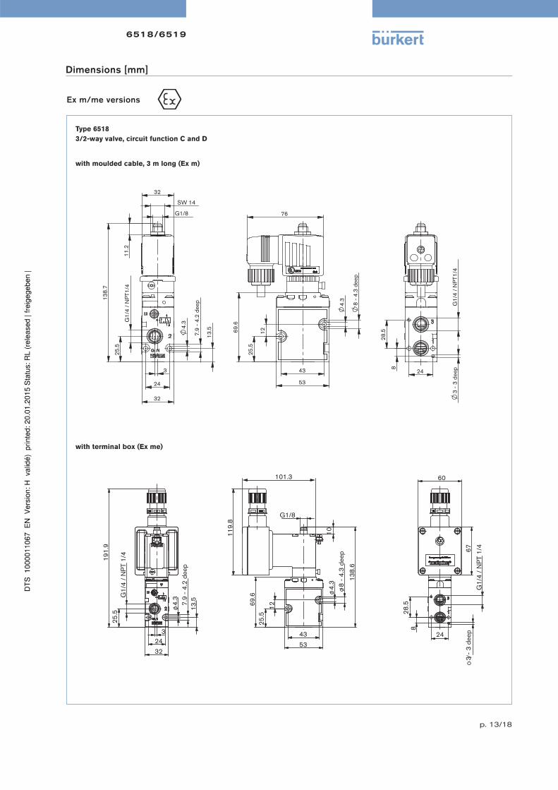
Ex m/me versions
with moulded cable, 3 m long (Ex m)
with terminal box (Ex me)
Dimensions [mm]
Type 6518
3/2-way valve, circuit function C and D
25.
5
12 69.
6
138
.6
4.
3
8 -
4.3
deep
G1/8
10
101.3
119
.8
43
53
60
67
24
8
28.
5
G1/
4 /
NP
T 1/
4
3 -
3 d
eep
24
4.
3
13.
5
32
7.9
- 4
.2 d
eep
G1/
4 /
NP
T 1/
4 2
5.5
191
.9
3
25.
5
12
69.
6
4.
3
8
- 4.
3 de
ep
43
53
76
3
- 3
deep
G1/
4 /
NP
T1/4
8
28.
5
24
4.
3
7.9
- 4
.2 d
eep
13.
5
24
32
G1/
4 /
NP
T1/4
25.
5
138
.7
G1/8
SW 14
11.
2
32
3

6518/6519
p. 14/18
Type 6519
5/2-way valve, circuit function H
with moulded cable, 3 m long (Ex m)
G1/
4 /
NP
T 1/
4 2
4
4.
5
11
- 3
dee
p
70
26
250
.2
G1/8
11.
2
SW14 32
32
76
36
44
4.
3
43
50
112
48
28.
5 2
6.5
G1/
4 /
NP
T 1/
4
3
- 3
deep
24
moulded cable(Standard 3 m long)
Ex m/me versions
Dimensions [mm]
5/2-way valve, circuit functions L and N
43
53
39.
6 3
6
4.
3
8
- 4.
3 de
ep
107
.7
76
28.
5 2
6.5
24
48
G1/
4 /
NP
T1/4
3 -
3 de
ep
moulded cable(Standard 3 m long)
24
32
4.
3
7.9
- 4
.2 d
eep
G1/
4 /
NP
T1/4
24
G1/8
SW 14
176
.8
11.
2
32
3

6518/6519
p. 15/18
Ex i versions
Type 6519
5/2-way valve, circuit function H
Type 6518
3/2-way valve, circuit function C
Dimensions [mm]
25,
5
12
4,
3
8
- 4,
3 tie
f
43
53
51
69,
6
23,5
3
- 3
tief
G1/
4 /
NP
T1/4
8
28,
5
24
4,
3
7,9
- 4
,2 ti
ef
13,
5
24
32
G1/
4 /
NP
T1/4
2
5,5
SW 14
145
,7
11,
2
G1/8
40
3
43
53
39.
6 3
6
4.
3
8
- 4.
3 de
ep
107
.7
51
23.5
28.
5 2
6.5
24
48
G1/
4 /
NP
T1/4
3 -
3 tie
f
24
32
4.
3
7.9
- 4
.2 d
eep
G1/
4 /
NP
T1/4
24
G1/8
SW 14
183
.8
40
11.
2
3
pp

6518/6519
p. 16/18
NAMUR standard version
Dimensions [mm]
Type 6519
3/2-way valve, circuit function C or 5/2-way valve, circuit function H
5.
3
24
51.
6
32
53
45
107
.7
3.95
20.5
48
G1/
4 /
NP
T1/4
5
1.6
32
37
G1/8
32
SW 14
176
.8
11.
2
6518/6519
p. 17/18
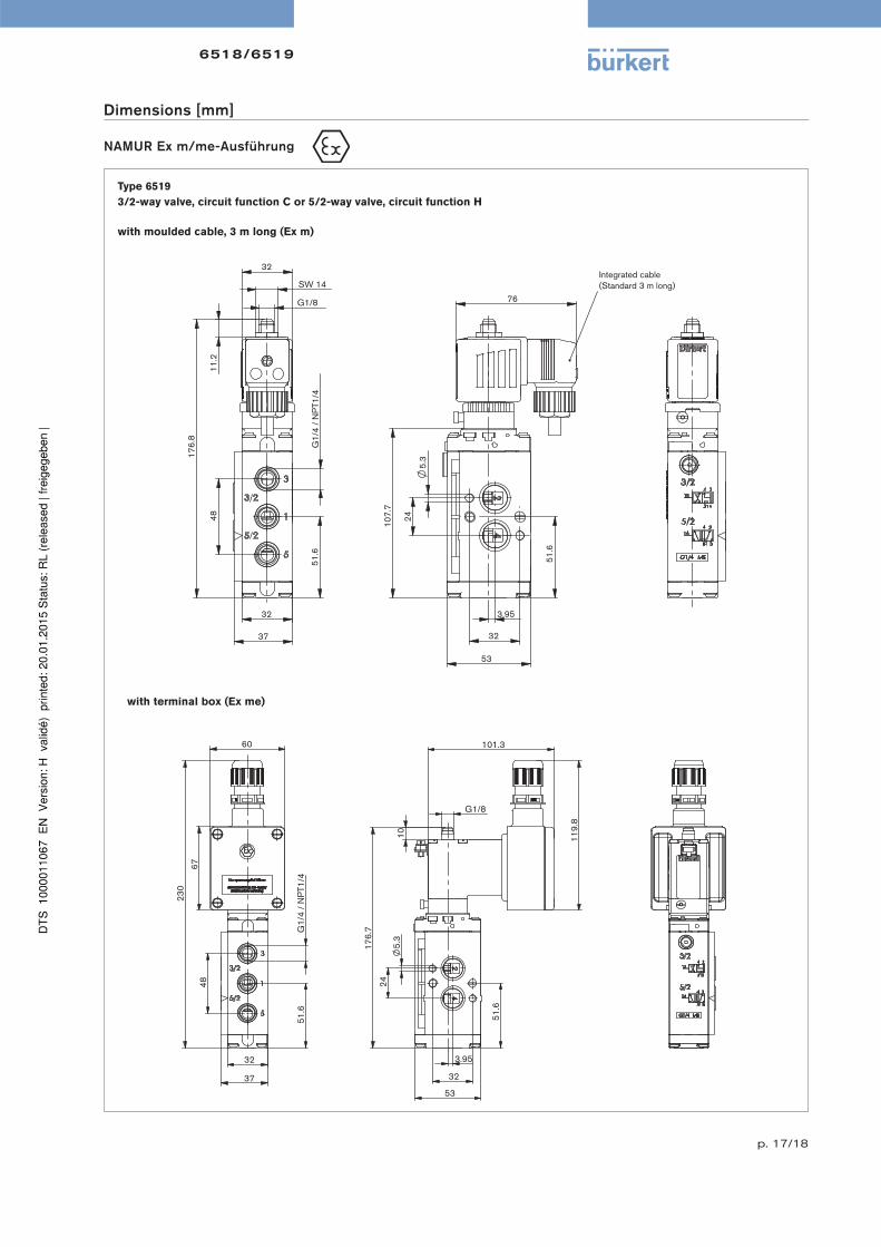
NAMUR Ex m/me-Ausführung
with moulded cable, 3 m long (Ex m)
with terminal box (Ex me)
Type 6519
3/2-way valve, circuit function C or 5/2-way valve, circuit function H
32
37
51.
6 G
1/4
/ N
PT1
/4
48
230
67
60
24
51.
6
32
53
176
.7
119
.8
101.3
G1/8
10
5.
3
3.95
Dimensions [mm]
5.
3
24
51.
6
32
53
107
.7
76
3.95
Integrated cable(Standard 3 m long)
48
G1/
4 /
NP
T1/4
5
1.6
32
37
G1/8
32
SW 14
176
.8
11.
2

6518/6519
p. 18/18
To fi nd your nearest Bürkert facility, click on the orange box www.burkert .com
Dimensions [mm]
In case of special application conditions,
please consult for advice.
We reserve the right to make technical changes without notice.
© Christian Bürkert GmbH & Co. KG 1412/7_EU-en_00891764
NAMUR Ex i version
5.
3
32
53
24
51.
6
107
.7
51
3.95
23.5 G1/8
SW 14
40
11.
2
183
.6 G
1/4
/ N
PT1
/4
48
51.
6
32
37
Type 6519
3/2-way valve, circuit function C or 5/2-way valve, circuit function H
Recommended