Vacuumapplications
−101.2kPa
−101.2
3 Port Solenoid ValveDirect Operated Poppet Type
54.5(Universal porting type)
A single valve with various valve functions
etc.
Low concentration ozone resistantRubber seal material: HNBR for main valve
N.C. valve N.O. valve
Divider valve Selector valve
Manifold typeBody ported type
33.229.5Mounting dimensions are
interchangeable with existing product
Power consumption
4 w1.8 w
Standard type
Energy-saving type
(Existing product: 4.8 W)
(Existing product: 2 W)
4 w1.8 w
CAT.ES11-107A
Series VT307
NewNew
RoHS
[Option]

Cv (PA)
Series
q Blow-off valve w Pressure release valve
e Selector valve
t Divider valve u Double-acting cylinder drive
y Single-acting cylinder drive
i Double-acting cylinder drive(Exhaust center)
r Valve for vacuum
Vacuum releasing airAtmospheric pressure or micro pressure
Vacuum pump Vacuum pad(P)1 2(A)
(R)3X
(P)1 2(A)
(R)3Plug
P1
P2
(P)1 2(A)
(R)3
2(A)
(R)3
(P)1
Tan
kT
ank
2(A)(P)1
(R)3
(R)3
(P)12
(A)
N.O. N.C.N.C. N.C.
2(A)2(A)
3(R)
1(P)
1(P)
3(R)
2(A)2(A)
3(R)
1(P)
1(P)
3(R)
Series VT307
Application examples
3 Port Solenoid Valve, Universal Porting Type Variations
A variety of valve options
Energy-saving type
Continuous duty type Vacuum specification type
Energy-saving type+
Vacuum specification type
Direct operated poppet type Pilot poppet type
VP300/500/700VT325VT317VT307
0.620.19 1.4 0.8 to 3.6
Poppet type
NewNew
http://www.smcworld.comRefer to the SMC website for details.
3 Port Solenoid Valve Direct Operated Poppet Type
Features 1

Body typeTO
Body portedFor manifold
Electrical entryGrommet DIN terminal
With surge voltage suppressor
∗ Semi-standard
Valve option
123∗4∗56∗7∗
∗ Semi-standard
Rated voltage
Model
VO307(-Q)
Applicable manifold type
Common or individual exhaust
AccessoriesFunction plate (DXT152-14-1A) Note)
Mounting screw (NXT013-3)
Note) It is not applicable to the continuous duty type. Refer to the accessories on page 5.
Manifold
JIS Symbol
Option
CE-compliant
DescriptionBracket
Part no.DXT152-25-1A (With screw)
Note) CE compliant: Electrical entry is applicable only for the DIN terminal.
∗ Electrical entry and light/surge voltage suppressor: D/DO/DZ/DOZ only
How to Order
(R)3
(A)2
1(P)
NilE∗Y∗V∗W∗
Standard typeContinuous duty typeEnergy-saving type
Vacuum specification typeEnergy-saving type, Vacuum specification type
Pressure specificationsNilK∗
Standard type (0.7 MPa)High-pressure type (1 MPa)
307 5 FG 1V T 01
BracketNilF
NoneWith bracket
NilQ
NoneCE-compliant∗
Thread typeNilFNT
RcG
NPTNPTF
Port sizeNil0102
Light/Surge voltage suppressorNil
S
Z
NoneWith surge voltage suppressor
(Grommet type only)With light/surge voltage suppressor
(DIN terminal type only)
[Option]
RoHS
DO: Without connector
D: With connectorG: 300 mm lead wireH: 600 mm lead wire
Surge voltage suppressor
100 VAC, 50/60 Hz200 VAC, 50/60 Hz110 VAC, 50/60 Hz220 VAC, 50/60 Hz24 VDC12 VDC
240 VAC, 50/60 Hz
1/8 (6A)Without port (For manifold)
1/4 (8A)
∗ Semi-standard
3 Port Solenoid ValveDirect Operated Poppet Type
Series VT307Rubber Seal
1

∗ Semi-standardNote 1) Based on dynamic performance test, JIS B 8374-1981. (Coil temperature: 20°C, at rated voltage,
without surge voltage suppressor)Note 2) Impact resistance: No malfunction occurred when it is tested with a drop tester in the axial direction
and at the right angles to the main valve and armature in both energized and de-energized states every once for each condition. (Values at the initial period)
Vibration resistance: No malfunction occurred in a one-sweep test between 45 and 1000 Hz. Test was performed at both energized and de-energized states in the axial direction and at the right angles to the main valve and armature. (Values at the initial period)
Note 3) At rated voltageNote 4) The value is different for continuous duty type (VT307E), and energy-saving type (VT307Y/W).
Refer to “Valve Options” shown below.
Note) Values for a single valve unit. It is not applicable to the manifold. Refer to the manifold specifications on page 5.
Make sure that dust and/or other foreign materials do not enter the valve from the unused port (e.g. exhaust port).
Caution
Continuous duty type: VT307EExclusive use of VT307E is recommended for continuous duty with long time loading.
Energy-saving type: VT307Y (VT307W)If low power consumption is required for electronic control, “VT307Y(W)” (1.8 W) is recommended.
Vacuum spec. type: VT307V (VT307W)This vacuum model has less air leakage than the standard model under low pressure. It is recommended for vacuum application.
1. This model is for continuous duty, not for high cycle rates. But even in low cycle rates, if energizing the valve more than once a day, please consult with SMC.
2. Energizing solenoid should be done at least once in 30 days.
Caution
Since this valve has slight air leakage, it can not be used for vacuum holding (including positive pressure holding) in the pressure container.
Caution
Note) Refer to Note 1) of the standard specifications.
Specifications different from standard are as follows.
Note) Refer to Note 1) of the standard specifications.
Operating pressure range –101.2 kPa to 0.1 MPaSpecifications different from standard are as follows.
Type of actuationFluidOperating pressure rangeAmbient and fluid temperatureResponse time Note 1)
Max. operating frequencyLubricationManual overrideMounting orientationImpact/Vibration resistance Note 2)
Enclosure
Direct operated type 2 position single solenoidAir
0 to 1 MPa (High-pressure type), 0 to 0.7 MPa (Standard type)–10 to 50°C (No freezing)20 ms or less (at 0.5 MPa)
10 HzNot required (Use turbine oil Class 1 ISO VG32, if lubricated.)
Non-locking push typeUnrestricted150/50 m/s2
Dustproof
Electrical entry
Coil rated voltage (V)
Allowable voltage fluctuation
Apparent power Note 3) Note 4) AC
DCACDC
DCAC (50/60 Hz)
InrushHolding
Grommet, DIN terminal100, 200, 110∗, 220∗, 240∗
24, 12∗–15 to +10% of rated voltage
12.7 VA (50 Hz), 10.7 VA (60 Hz) 7.6 VA (50 Hz), 5.4 VA (60 Hz)
Without indicator light: 4 W, With indicator light: 4.2 WVaristor, LEDDiode, LED
Power consumption Note 3) Note 4)
Light/Surge voltage suppressor(DIN terminal type only)
C[dm3/(s·bar)] b Cv
Weight
Grommet
Portsize
1/8
1/4
Valve model
VT307VT307V (Vacuum spec. type)VT307E (Continuous duty type)VT307Y (Energy-saving type)VT307W (Energy-saving, Vacuum spec. type)VT307VT307V (Vacuum spec. type)VT307E (Continuous duty type)VT307Y (Energy-saving type)VT307W (Energy-saving, Vacuum spec. type)
C[dm3/(s·bar)] b Cv C[dm3/(s·bar)] b Cv C[dm3/(s·bar)] b Cv
0.71
0.41
0.71
0.49
0.35
0.26
0.31
0.20
0.18
0.10
0.19
0.12
0.68
0.44
0.71
0.44
0.27
0.35
0.25
0.34
0.17
0.11
0.17
0.11
0.65
0.48
0.68
0.48
0.36
0.27
0.33
0.17
0.17
0.12
0.17
0.12
0.63
0.35
0.71
0.46
0.35
0.33
0.26
0.28
0.17
0.10
0.18
0.11
Flow-rate characteristics1 → 2 (P → A) 2 → 3 (A → R) 3 → 2 (R → A) 2 → 1 (A → P)
0.15 kg
Apparent power/AC
InrushHolding
7.9 VA (50 Hz), 6.2 VA (60 Hz) 5.8 VA (50 Hz), 3.5 VA (60 Hz)
Power consumption/DC 1.8 W, With indicator light: 2 W30 ms or less (at 0.5 MPa)Response time Note)
Specifications different from standard are as follows.1.8 W, With indicator light: 2 W25 ms or less (at 0.5 MPa)
Power consumption/DCResponse time Note)
Valve Options
Standard Specifications
Flow-rate Characteristics/Weight
Series VT307
2

Manual override
q q
w w
e e
r
r
t
yu
(Å)™
£(Â)
¡(∏) (Å)™ ¡(∏)
£(Â)
21
1 2
Ground
Voltage100 VAC200 VAC
DCOthers
ColorBlueRed
Red (+), Black (–)Gray
Terminal no.DIN terminal
1 2+ −
Description
DIN connector
Part no.B1B09-2A (Standard)
GM209NJ-B17 (CE-compliant)
Connector for DIN Terminal
How to Use DIN Terminal
1. Disassembly1) After loosening the screw q, then if the
housing w is pulled in the direction of the screw q, the connector will be removed from the body of equipment (solenoid, etc.).
2) Pull the screw q out of the housing w.3) On the bottom part of the terminal block e,
there’s a cut-off part o. If a small flat head screwdriver is inserted between the opening in the bottom, terminal block e will be removed from the housing w.
4) Remove the cable gland r, plain washer t and rubber seal y.
2. Wiring1) Pass the cable u through the cable gland r,
plain washer t and rubber seal y in this order, and then insert them into the housing w.
2) Loosen the screw !1 attached to the terminal block e. Then, pass the lead wire !0 through the terminal block e and tighten the screw !1 again.Note 1) Tighten within the tightening torque of
0.5 N·m ±15%.Note 2) Cable u outside diameter: ø6 to ø8 mmNote 3) Crimped terminal like round-shape or
Y-shape cannot be used.
3. Assembly 1) Pass the cable u through the cable gland r,
plain washer t and rubber seal y in this order and connect to the terminal block e. Then, mount the terminal block e on the housing w.(Push it down until you hear the click sound.)
2) Put the rubber seal y and plain washer t in this order into the cable entry of the housing w, and then tighten the cable gland r securely.
3) Insert the gasket i between the bottom part of terminal block e and the plug attached to the equipment. Then, screw in q from the top of the housing w to tighten it. Note 1) Tighten within the tightening torque of 0.5
N·m ±20%.Note 2) Connector orientation can be changed
180° depending on how the housing w and the terminal block e are assembled.
De-energized EnergizedLight/Surge Voltage Suppressor
Caution
Electrical Connection
Lead Wire Color
DIN terminal is connected inside as in the figure below. Connect to the corresponding power supply.
DIN terminal block
· Applicable cable O.D.ø6 to ø8
Construction
Terminal no. 2
Coil
Terminal no. 1
Terminal no. 2 (–)
Coil
Terminal no. 1 (+)
In the case of indicatorlight assembly
In the case of indicatorlight assembly
!0
q
er
t
y
ui o!1
w
1234
No. MaterialDescriptionAluminum die-casted
Aluminum, HNBRStainless steel
BodyPoppet valveReturn springMolded coil Resin
NoteColor: White
Operation principle<De-energized>Poppet valve w is pushed upward by the return spring e, port ¡ is closed. Then, port ™ and port £ are connected.Air flow direction:Port ¡ ←→ Block, ™ ←→ £
<Energized>When energizing the molded coil r, the arma-ture t is magnetically attracted to the core y, and through the push rod u, it pushes down the poppet valve w and port £ is closed. Then, port ¡ and port ™ are connected. At this time, there will be gaps between the armature t and the core y, but the armature t will be magnetically firmly attracted to the core y.Air flow direction:Port ¡ ←→ Port ™, Port £ ←→ BlockComponent Parts
AC
DC
Series VT3073 Port Solenoid ValveDirect Operated Poppet Type
3
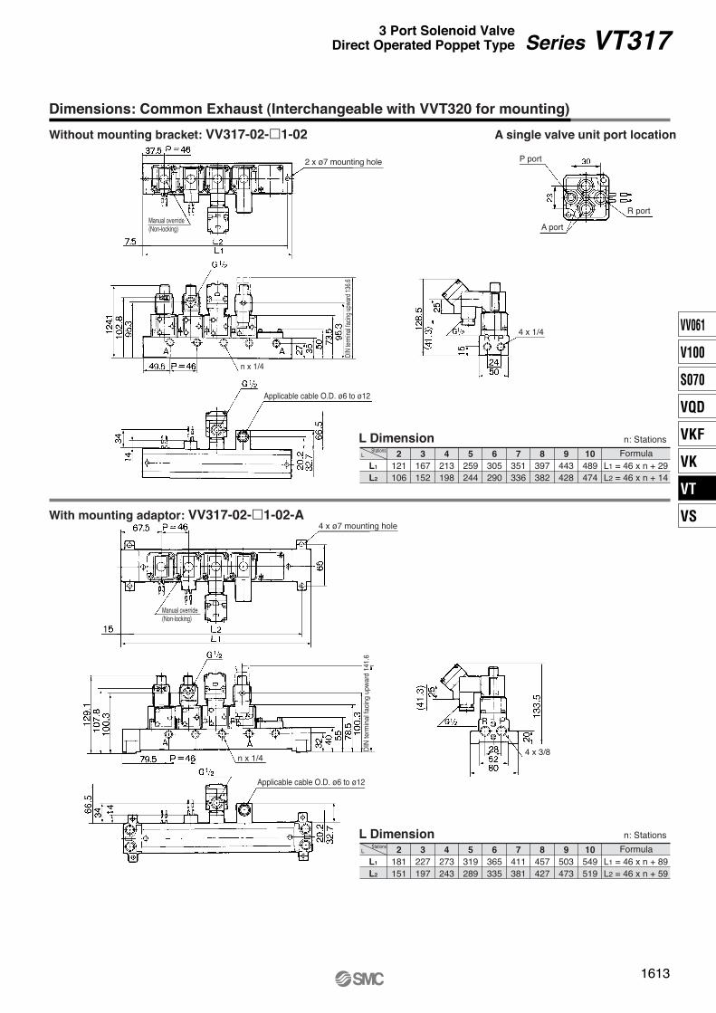
Note) There is also “VT307-H1” (lead wire length: 600 mm).
Max
. 10
67.6
54.5
(14.5)
(37)
(28)(4.5)
(4.5
)
(42)
(33)
(17.
2)
13.5
29.5
16.7
25
18.6
(3.2
)
10.3
33.2
16.525.6
13 1
3
2
Pg9
Applicable cable O.D.ø6 to ø8
Manual override(Non-locking)
2 x ø4.5(For mounting)
M4 x 0.7 thread depth 7(Mounting screw)
1/4", 1/8"(Piping port)
40.3
(14.5)
47.2
13.5
29.5
16.7
25
18.6
(17.
2)
(4.5)
(37)
(28)(4.5
)
(42)
(33)
54.5
10.3
(3.2
)
33.2
16.5
13
25.6
1
3
2
G: ≈300 H: ≈600(Lead wire length)
Manual override(Non-locking)
2 x ø4.5(For mounting)
M4 x 0.7 thread depth 7(Mounting screw)
1/4", 1/8"(Piping port)
65
56
Dimensions
Grommet: VT307-G1
DIN terminal: VT307-D1
Series VT307
4

How to Order Manifold Base
Exhaust port type23
Common exhaustIndividual exhaust
Valve stations
VV307
2 stations
20 stations
02
20
05 2 01
0102
A port size (Base mounted)
VT307 manifold
Dummy symbol Mounting bracket
01 F
Max. 20 stations
NilFNT
RcG
NPTNPTF
Thread type
Option
Note) For 6 stations or more, supply air both sides of P port. The common exhaust type should exhaust from both of the R port.
Manifold Specifications
Description Part no.Function plate (With gasket) Note)
Mounting screws NXT013-3
Qty.1 pc.2 pcs.
Note) DXT060-51-13B, DXT152-14-1B are for the continuous duty type.
Accessories for Applicable Solenoid Valve
Flow-rate Characteristics/Weight
Common exhaustVV307-01-052--F
Individual exhaustVV307-01-053--F
Ordering example: VV307-01-052-01-F··· 1 pc. (5 station manifolds base) VO307-1G1················4 pcs. DXT060-51-13A·········1 pc. (Blanking plate)
Manifold typeMax. number of stationsApplicable solenoid valve
B mount20 stations Note)
VO307- (-Q)
Exhaust portSymbol
2
3
Type
Common
Individual
Port location (Direction)/Port sizeP RA
Description Part no.Blanking plate (With gasket, screw) Note)
C[dm3/(s·bar)]
0.34
0.30
b
0.28
0.18
Cv
0.089
0.070
Weight
Grommet
0.15 kg
Valve model
VO307VO307V (Vacuum spec. type)
VO307E (Continuous duty type)
VO307Y (Energy-saving type)
VO307W (Energy-saving, Vacuum spec. type)
C [dm3/(s·bar)]
0.34
0.30
b
0.22
0.15
Cv
0.082
0.072
C[dm3/(s·bar)]
0.36
0.32
b
0.28
0.20
Cv
0.091
0.075
C[dm3/(s·bar)]
0.34
0.30
b
0.18
0.15
Cv
0.080
0.069
Flow-rate characteristics1 → 2 (P → A) 2 → 3 (A → R) 3 → 2 (R → A) 2 → 1 (A → P)
Series VT307Manifold Specifications
VT307 manifold is available both as a common exhaust and individual exhaust model.
Manifold valve can be easily convert-ed from N.C. (Normally Closed) to N.O. (Normally Open) merely by turn-ing over the function plate.
··· ···
common exhaust/individual exhaust1 8
individual exhaust1 4
Base (Side)1 8
Base (Side)1 4
Base (Top)1 8
Base (Side)1 8
Base (Side)1 8
Base (Side)1 8 1 4,
DXT060-51-13 AB
DXT152-14-1 AB
∗ Specify model number of the manifold base, applicable valves and blanking plates when ordering.Refer to page 1 for the model number of the valves.
5
nL
L1
L2
28862
3114 88
4140114
5166140
6192166
7218192
8244218
9270244
10296270
FormulaL1 = 26 x n + 36L2 = 26 x n + 10
n: StationsL Dimension
Dimensions: Common Exhaust
VV307-01-2-01-F
111
G: ≈
300
H: ≈
600
50.6
83
43.5
39.3
21.6
19
1
209
20 13
56.7
26.7
38294.
6
12 18
13L2
L1
64
Max
. 10
77.1
(35)
31
40
235
DIN terminal (D, DZ)
Grommet (G, H)
Manual override(Non-locking)
Pg9
1/8"[1(P), 3(R) port]
For 4 x M4(For mounting)
Applicable cable O.D.ø6 to ø8
(Pitch)P = 26
1/8"[2(A) port]
(Station n) (Station 1)
(Pitch)P = 26
PR
PR
A A
Series VT307
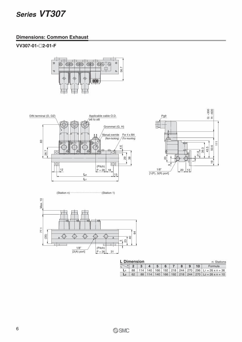
6
nL
L1
L2
27664
3102 90
4128116
5154142
6180168
7206194
8232220
9258246
10284272
FormulaL1 = 26 x n + 24L2 = 26 x n + 12
n: StationsL Dimension
Dimensions: Individual Exhaust
VV307-01-3--F
55.2
1
111
19G
: ≈30
0H
: ≈60
050
.6
43.5
39.3
21.6
18.5
2011
62.5
Max
. 10
75.6
25
3829
4.6
83
27
12
L1
L2
28.5
6
(1)
40
31
22
5
For 4 x M4(For mounting)
Pg9
1/4"[1(P) port]
1/8"[3(R) port]
(Pitch)P = 26
DIN terminal (D, DZ)
(Pitch)P = 26
Applicable cable O.D.ø6 to ø8
Grommet (G, H)
Manual override(Non-locking)
1/4", 1/8"[2(A) port]
(Pitch)P = 26
R R P
AA
Series VT3073 Port Solenoid ValveDirect Operated Poppet Type
(Station n) (Station 1)
7

Function plate
Figure: For N.C.
Function plateNo mark
NO
SpecificationsN.C.N.O.
Port positions for manifold solenoid valve body
Port c
Port x
Port z
Mounting
Piping
Warning
Caution
When mounting a valve on the manifold base, N.C. and N.O. can be reversed by the function plate orientation. Also, since the cylinder operates in reverse, confirm if the function plate is correctly mounted or not.
Changing from N.C. to N.O.
Caution
Caution
Function plate
N.O. specification
N.C. specification
1. Each valve is fixed to the manifold base with two M4 mounting screws. Tighten the screws firmly when re-mounting.
2. For mounting, tighten M4 or equivalent screws evenly into the mounting holes of the manifold base. Tightening torque of the mounting screw (M4): 1.4 N·m
1. For the common exhaust type, pressurization or evacuation of the 3(R) port can cause a malfunction.
This product is delivered as N.C. valve.If N.O. valve is required, remove mounting screws of the required valve and turn over the function plate. (Make sure that there are gaskets on both sides of the plate.) Then, tighten the mounting screws to fix the valve to the manifold base.
Series VT307Specific Product PrecautionsBe sure to read before handling. Refer to back cover for Safety Instructions and “Handling Precautions for SMC Products” (M-E03-3) for 3/4/5 Port Solenoid Valve Precautions.
8

1. The compatibility of the product is the responsibility of the person who designs the equipment or decides its specifications.Since the product specified here is used under various operating conditions, its compatibility with specific equipment must be decided by the person who designs the equipment or decides its specifications based on necessary analysis and test results. The expected performance and safety assurance of the equipment will be the responsibility of the person who has determined its compatibility with the product. This person should also continuously review all specifications of the product referring to its latest catalog information, with a view to giving due consideration to any possibility of equipment failure when configuring the equipment.
2. Only personnel with appropriate training should operate machinery and equipment.The product specified here may become unsafe if handled incorrectly. The assembly, operation and maintenance of machines or equipment including our products must be performed by an operator who is appropriately trained and experienced.
3. Do not service or attempt to remove product and machinery/equipment until safety is confirmed.1. The inspection and maintenance of machinery/equipment should only be
performed after measures to prevent falling or runaway of the driven objects have been confirmed.
2. When the product is to be removed, confirm that the safety measures as mentioned above are implemented and the power from any appropriate source is cut, and read and understand the specific product precautions of all relevant products carefully.
3. Before machinery/equipment is restarted, take measures to prevent unexpected operation and malfunction.
4. Contact SMC beforehand and take special consideration of safety measures if the product is to be used in any of the following conditions. 1. Conditions and environments outside of the given specifications, or use
outdoors or in a place exposed to direct sunlight.2. Installation on equipment in conjunction with atomic energy, railways, air
navigation, space, shipping, vehicles, military, medical treatment, combustion and recreation, or equipment in contact with food and beverages, emergency stop circuits, clutch and brake circuits in press applications, safety equipment or other applications unsuitable for the standard specifications described in the product catalog.
3. An application which could have negative effects on people, property, or animals requiring special safety analysis.
4. Use in an interlock circuit, which requires the provision of double interlock for possible failure by using a mechanical protective function, and periodical checks to confirm proper operation.
Warning
Limited warranty and Disclaimer/Compliance Requirements The product used is subject to the following “Limited warranty and Disclaimer” and “Compliance Requirements”.Read and accept them before using the product.
1. The product is provided for use in manufacturing industries.The product herein described is basically provided for peaceful use in manufacturing industries. If considering using the product in other industries, consult SMC beforehand and exchange specifications or a contract if necessary. If anything is unclear, contact your nearest sales branch.
Caution
Limited warranty and Disclaimer1. The warranty period of the product is 1 year in service or 1.5 years after
the product is delivered, whichever is first.∗2)
Also, the product may have specified durability, running distance or replacement parts. Please consult your nearest sales branch.
2. For any failure or damage reported within the warranty period which is clearly our responsibility, a replacement product or necessary parts will be provided. This limited warranty applies only to our product independently, and not to any other damage incurred due to the failure of the product.
3. Prior to using SMC products, please read and understand the warranty terms and disclaimers noted in the specified catalog for the particular products.
∗2) Vacuum pads are excluded from this 1 year warranty.A vacuum pad is a consumable part, so it is warranted for a year after it is delivered. Also, even within the warranty period, the wear of a product due to the use of the vacuum pad or failure due to the deterioration of rubber material are not covered by the limited warranty.
Compliance Requirements1. The use of SMC products with production equipment for the manufacture of
weapons of mass destruction (WMD) or any other weapon is strictly prohibited.
2. The exports of SMC products or technology from one country to another are governed by the relevant security laws and regulations of the countries involved in the transaction. Prior to the shipment of a SMC product to another country, assure that all local rules governing that export are known and followed.
These safety instructions are intended to prevent hazardous situations and/or equipment damage. These instructions indicate the level of potential hazard with the labels of “Caution,” “Warning” or “Danger.” They are all important notes for safety and must be followed in addition to International Standards (ISO/IEC)∗1), and other safety regulations.
∗1) ISO 4414: Pneumatic fluid power – General rules relating to systems. ISO 4413: Hydraulic fluid power – General rules relating to systems. IEC 60204-1: Safety of machinery – Electrical equipment of machines. (Part 1: General requirements) ISO 10218-1: Manipulating industrial robots – Safety. etc.
Caution indicates a hazard with a low level of risk which, if not avoided, could result in minor or moderate injury.
Warning indicates a hazard with a medium level of risk which, if not avoided, could result in death or serious injury.
Caution:
Warning:
Danger :Danger indicates a hazard with a high level of risk which, if not avoided, will result in death or serious injury.
Safety Instructions
Safety Instructions Be sure to read “Handling Precautions for SMC Products” (M-E03-3) before using.
Akihabara UDX 15F, 4-14-1, Sotokanda, Chiyoda-ku, Tokyo 101-0021, JAPANPhone: 03-5207-8249 Fax: 03-5298-5362http://www.smcworld.com© 2012 SMC Corporation All Rights Reserved
Specifications are subject to change without prior notice and any obligation on the part of the manufacturer.
1st printing QW printing QW 8150SZ Printed in Japan.D-G

VV061
V100
S070
VQD
VKF
VK
VT
VS
Q
JIS Symbol
T0
GHCTD
317 021 GV T
02
RcG
NPTNPTF
DTCHG
—————
———SZ
Manifold
Compact yet provides a large flow capacityDimensions (W x H x D)······45 x 89.5 x 45
(Grommet)C: 2.6 dm3/(s·bar)(Passage 2 → 3)
Suitable for use in vacuum applications–101.2 kPa(For vacuum specifications: VT/VO317V)
A single valve with 6 valve functions(Universal porting type)Selective porting can provide 6 valve functions, such as N.C. valve, N.O. valve, Divider valve, Selector valve etc.
Body typeBody ported
Manifold
Electrical entryGrommet, 300 mm lead wireGrommet, 600 mm lead wire
ConduitConduit terminal
DIN terminal
Port size
NilWithout port
(For manifold)(8A)1 4
Thread typeNilFNT
100 VAC, Hz200 VAC, Hz110 VAC, Hz220 VAC, Hz
24 VDC12 VDC
240 VAC, HzOther
∗ Option
Light/Surge voltage suppressor
Surge voltage suppressor mounting part (For “G”)
Electricalentry
• Note)• Note)
Symbol
Nil
∗ Option
Valve option
Rated voltage
Nil Standard typeE ∗ Continuous duty typeV ∗ For vacuum
50 6050 6050 6050 60
50 60
S: With surge voltage suppressorNote) Refer to the figure below.
Z: With light/surge voltage suppressor∗ As to the case of rated voltage
[Others (9)], please contact SMC.
Surge voltage suppressor
123 ∗
4 ∗
56 ∗
9 ∗7 ∗
•• ••• Note)
3 Port Solenoid ValveDirect Operated Poppet Type
Series VT317Rubber Seal
CE-compliant
CE-compliant ∗
∗ Electrical entry: D/DO only
Nil ——
Model
VO317(-Q)
Applicable manifold type
Common or individual exhaust
AccessoryO-ring (P10, 4 pcs.) Note)
Bolts (M4 x 0.7 x 20, 2 pcs.)
Note) It is not applied to “Continuous duty type”. Refer to the accessories on page 1612.
[Option]
1609
How to Order
P1569-1636-E.qxd 08.9.2 4:01 PM Page 1609

12
Standard Specifications
Construction
b Cv
0.29kg
b Cv b Cv b Cv
2.4 0.26 0.62 2.6 0.34 0.67 2.8 0.25 0.67 2.5 0.37 0.66
Flow Characteristics/Mass
De-energized Energized
Option
Fluid
Ambient and fluid temperatureResponse time (1)
LubricationManual override
Shock/Vibration resistance (2)
Enclosure
Air
–10 to 50°C (No freezing. Refer to page 5.)
Type of actuation Direct operated type 2 position single solenoid
Operating pressure range 0 to 0.9 MPa
30 ms or less (at the pressure of 0.5 MPa)
Not required (Use turbine oil Class 1 ISO VG32, if lubricated.)Max. operating frequency 10 Hz
Non-locking push typeMounting orientation Unrestricted
150/50 m/s2
Dustproof
∗ OptionNote 1) Based on dynamic performance test, JIS B 8374-1981. (Coil temperature: 20°C, at rated voltage,
without surge suppressor)Note 2) Impact resistance: No malfunction occurred when it is tested with a drop tester in the axial direction
and at the right angles to the main valve and armature in both energized and de-energized states every once for each condition. (Values at the initial period)
Vibration resistance: No malfunction occurred in a one-sweep test between 45 and 1000 Hz. Test was performed at both energized and de-energized states in the axial direction and at the right angles to the main valve and armature. (Values at the initial period)
Note 3) At rated voltage
Electrical entry
Coil rated voltage (V)
Allowable voltage fluctuation
Apparent power (3) AC
DCACDC
DCAC (50/60 Hz)
InrushHolding
Grommet, Conduit, Conduit terminal, DIN terminal
100, 200, 110 ∗, 220 ∗, 240 ∗
24, 12 ∗
–15 to +10% of rated voltage19 VA (50 Hz), 16 VA (60 Hz) 11 VA (50 Hz), 7 VA (60 Hz)
Without indicator light: 6 W, With indicator light: 6.3 WVaristor, Neon bulb
Varistor, LED (Neon bulb for 100 V or more)
Power consumption (3)
Light/Surge voltage suppressor(Not applicable for grommet type)
C [dm3/(s·bar)] C [dm3/(s·bar)] C [dm3/(s·bar)] C [dm3/(s·bar)]1 → 2 (P → A) 2 → 3 (A → R) 3 → 2 (R → A) 2 → 1 (A → P)
Mass
GrommetValve model
VT317VT317V (Vacuum spec. type)VT317E (Continuous duty type)
Flow characteristics
Note) Values for a single valve unit. It differs in the manifold case. Refer to manifold specifications on page 1612.
No. DescriptionBodySpool valve
MaterialAluminum die-castedAluminum, NBR
NoteColor: Platinum silver
Operation principles<De-energized>Spool valve w is pushed upward by the return spring e, port P is closed, and port A and port R are opened.
<Energized>When an electric current is applied to the molded coil r, the armature t is attracted to the core y, and through the push rod u, it pushes down the spool valve w. Then, port P and port A are connected. At this time, there will be gaps between the armature t and the core y, but the armature will be magnetically attracted to the core y.
Component Parts
Caution
Caution
1. This model is for continuous duty, not for high cycle rates. But even in low cycle rates, if energizing the valve more than once a day, please consult with SMC.
2. Energizing solenoid should be done at least once in 30 days.
Vacuum spec. type: VT317VThis vacuum model has less air leakage than the standard model under low pressure. It is recommended for vacuum application.
1. Since this valve has slight air leakage, it can not be used for vacuum holding (including positive pressure holding) in the pressure container.
Operating pressure range –101.2 kPa to 0.1 MPa
Specifications different from standard are as follows.
Continuous duty type: VT317EExclusive use of VT317E is recommended for continuous duty with long time loading.
1610
Series VT317
P1569-1636-E.qxd 08.9.2 4:01 PM Page 1610

VV061
V100
S070
VQD
VKF
VK
VT
VS
����������
������ ������� ������� �������
������ ������� ������� ��� ������� �������
����� ���� � � �� ���������� ����� �� ������ ��� ���
� ��� ����� ����� �� ������
�!� "������� "��
#��$� �%���
����� �&'���
( ) #� ��$���� �� �
*� ��" ��$���� �#+�
!� ,���� "�����
+ "������ "� -�.
( ) #� ) � ,� /����� ��$����
�!� "������� "��
#��$� �%���
����� �&'���
( ) #� ��$���� �� �
*� ��" ��$���� �#+�
!� ,���� "�����
+ "������ "� -�.
( ) #� ) � ,� /����� ��$����
� (0� ����� �� ������
�!� "������� "��
#��$� �%���
����� �&'���
( ) #� ��$���� �� �
*� ��" ��$���� �#+�
!� ,���� "�����
+ "������ "� -�.
( ) #� ) � ,� /����� ��$����
�!� "������� "��
#��$� �%���
����� �&'���
( ) #� ��$���� �� �
*� ��" ��$���� �#+�
!� ,���� "�����
+ "������ "� -�.
( ) #� ) � ,� /����� ��$����
12�
���
��
,�&
��$"
��
���
�� �
�
3"" &�/ � &�/ � 4 1
5� �� 5�(
� ) �6+ � ) �6+
� ) �6+ � ) �6+
#�
) �
�
����
Series VT317� �� �������� �������� ������ ����� � ��
P1569-1636-E.qxd 08.9.2 4:01 PM Page 1611
VV317
RcG
NPTNPTF
05 1 AA
02 02
Manifold Specifications
Accessory for Applicable Solenoid
Option
b Cv
0.32kg
b Cv b Cv b Cv
2.0 0.11 0.47 2.2 0.12 0.49 2.0 0.14 0.45 2.1 0.14 0.48
Flow Characteristics/Mass
VV317-02-051-02-A
VV317-02-051-02
VV317-02-053-02
Series VT317Manifold Specifications
How to Order Manifold
VT317 manifold is B mount style and available both as a common exhaust and individual exhaust model.
Common exhaust
Individual exhaust
Mass
GrommetValve model
Flow characteristics
C [dm3/(s·bar)] C [dm3/(s·bar)] C [dm3/(s·bar)] C [dm3/(s·bar)]1 → 2 (P → A) 2 → 3 (A → R) 3 → 2 (R → A) 2 → 1 (A → P)
VO317VO317V (Vacuum spec. type)VO317E (Continuous duty type)
∗ Please indicate manifold base type, applicable manifold valve and blanking plate when ordering.
Manifold typeMax. number of stations
Applicable solenoid valve
B mount20 stations (1)
VO317�-���(-Q) (3)
Exhaust portSymbol
1
3
Port location (Direction)/Port sizeA
Base (Side)1 4
1 4
Base (Side)
Note 1) For more than 3 stations, supply air both sides of P port. The common exhaust type should exhaust from both of the R port.
Note 2) In the case of common exhaust type, R and P ports size can be Rc 3/8 by using a mounting adaptor.
Note 3) Can also be applied to Series VVT320 manifold.
Type
Common (2)
Individual
PBase (Side)
Base (Side)1 4
( )1 4 3 8
R
Base (Side)1 4
Base (Side)( )1 4 3 8
Description Part no.Blanking plate (With screw, O-ring) PVT317-53-1A
Mounting bracket (With screw)DXT010-37-4
(For common exhaust)
Thread typeNilFNT
OptionMounting bracket ∗
A port size (Base piping)1/4
VT317 manifold
Base type: 1/4
Valve stations
2 stations
20 stations
02
20Max. 20
Symbol
Symbol
1
Passage Porting specifications
ASide
RPCommonCommon
3 SideIndividualCommon
Ordering example: VV317-02-051-02-A······· 1 pc.
(5-station manifold base) VO317-1G······················ 4 pcs. PVT317-53-1A··············· 1 pc.
(Blanking plate)
NoteStandard type vacuum specifications type
Continuous duty type
Description
O-ring
Hexagon socket head screw
Qty
4
2
Part no.P10
P10FMax. 0.7 x 20
··· ···
∗ Common exhaust type only
1612
P1569-1636-E.qxd 08.9.2 4:01 PM Page 1612
VV061
V100
S070
VQD
VKF
VK
VT
VS
� ����������������
�
�
��
�
�
�
��
�
� �
���
�
��
��
�
���
���
�
�
�
�
��
��
�
���
� �
�
���
��
�������
� � �� � � � �
�� � �� � � � ��
�� ��������
���������
�
��
�
�
��
�
�
��
��
�
�
���
���
�
���
���
�
��
���
�
��
��
�
���
��
�
��
� �
�������
� � �� � � � ��
�� � �� � � � �
�� ��������� ��������
������� �! �� �! "#$# %� �� %�
������� �! �� �! "#$# %� �� %�
& ����
� ����
' ����
$()
�!��
����*����+
��,��-�
�#�
$()
�!��
����*����+��,��-
�#�
���������� ���� ������� ���������� ��!"� #��� $$%��� &� ������ '
� � % �������+ .��!
/����� �0!���-!1)��2���3��+4
/����� �0!���-!1)��2���3��+4
� � % �������+ .��!
� � 5�
� � 5�
� � 5�� � �5
��
(����� ������ !���)��� $$��*��*�*��
(��� ������ �+�,��� $$��*��*�*��*-
- ��� "� .�".� ���� ,�� "�����
Series VT317� /�� 0"���+ $�".������� 1,�����+ /,,�� %2,�
P1569-1636-E.qxd 08.9.2 4:01 PM Page 1613
���� ����
���������
���� ��� � ��� ���� � ����
� ������������
�
��
��
�
�
��
�
��
��
�
� �
��
�
���
���
�
���
���
�
��
���
�
���
���
���
���
�!
���
���
������
� � �� � � ��
�� � �� � � �
������
��!"# ����$ %��%#� �"# ���&�'(��#) �"# ����$ ��#���� ��'#*�'#'� +& �� �� ���#' � �"# ,�$'��#*��) *#*�#' #-��.�#� ��/���&�*��� 0�� �� (/ �#&#���$ �", � �,��*" %#� &�� ���� � �����.#*�&�*�����
��1�*" %��%# �� &��#' � �"# ���&�' (��#,��" �, 0� ����$ �*�#,�� 2�$"�#�"# �*�#,� #%#�/ ,"# �#3����$�2�$"�#�$ ��-�# & �"# ����$�*�#, 40�5 �� �6�
�� �� ����$) ��$"�# 0� � #-��%��#��*�#,� #%#�/ �� �"# ����$ "�#�& �"# ���&�' (��#�
"�#����$ %��� %������ �#����&�$��' ����(���� &' � ���%$� ��! )� ��� ���������� �)���� �� ���� �) ���� �� �)�����) �� &�$* �� ����
7��%#1�"���� .�� �/.#
��� #�"����
+'�%�'��� #�"����
� �"�$�$ &�� ���� � ����
2"�� .�'�*� �� '#��%#�#' �� ���� %��%#� +& ���� %��%# �� ##'#') �#�%# ����$ �*�#,� & �"#
�#-���#' %��%# �' ��� �"# %��%# �� ��8 '#$�##�� 40�9# ���# �"�� �"#�# ��# �3��$� &��#' �
.����� & �"# %��%# ���&�*#�5 2"#) ��$"�# �"# ����$ �*�#,� � &�� �"# %��%# � �"# ���&�'
(��#�
+���
�����
0����%#���'#4�3�*9�$5
�'��� 4�5
:���#� 4:5
�'��� �#����� 425
;+� �#����� 4;5
<..��*�(�# *�(�# ��;� =� � = �
� � =� ����$ "�#
;+�
�#��
��
�&�
*�
$�
.,
��'
4 �
���
5
�����
,� ���� � ���) &���� ��)$� � -���� � ��� ������� �� �) � �� .����' /�������� �) %� �� � � � �� �(�(�
��� .$��) 0�$#� ����������
� � >�
�������1 /)�#�)��$ 23�����
+����� ���� &���4��(00���5!�5��5!�
� �
Series VT317
P1569-1636-E.qxd 08.9.2 4:01 PM Page 1614

VV061
V100
S070
VQD
VKF
VK
VT
VS
Ground
Caution Caution
Electrical Connection
Change of Electrical Entry Angle
Varistor
None
AC
DC
AC
DC
Neon bulb
Varistor
100 VDCNeon bulb
Varistor
Varistor
Diode
48 VDC or less
Varistor
Light/Surge Voltage Suppressor
Lead Wire Color (Grommet)
Series VT317Specific Product PrecautionsBe sure to read before handling. Refer to Front matters 58 and 59 for Safety Instructions and pages 3 to 7 for 3/4/5 Port Solenoid Valve Precautions.
Voltage100 VAC200 VAC
DCOther
ColorBlueRed
Red (+), Black (–)Gray
DIN terminal is connected inside as in the figure below. Connect to the corresponding power supply.
1. A bleed port for the main valve is located at the bottom of the solenoid valve. Since blocking it causes malfunction, do not block it.
∗ Ordinarily, when the solenoid valve is mounted on a metal surface, it can breathe through the breather hole, via the breather groove. However, in particular, if the surface to be mounted is made of the rubber, the rubber could deform and block the hole.
2. Make sure that dust and/or other foreign materials should not enter the valve from the unused port (e.g. exhaust port). Also, since there is a bleed port for the armature in the manual override, do not allow accumulation of dust and/or other foreign materials to block bleed port.
How to Calculate the Flow RateFor obtaining the flow rate, refer to front
matters 44 to 47.
1. Series VT317 can change electrical entry angle. (4 positions)
2. How to change: Loosen the nut (1), remove the coil (2) from the body assembly (3), place the positioning pin (4) at the required place, put back the coil (2) to its place, and tighten sufficiently with lock nut (1).
Protection circuit for light/surge voltage suppressor is not the polarity type.
Grommet (G)Conduit (C)
Conduit terminal (T)DIN terminal (D)
Light/Surge voltagesuppressor (Z)
Surge voltagesuppressor (S)
Coi
lC
oil
Coi
lC
oil
Coi
l
Coi
l
(1)
(2)
(3)
(4)
Manual override
Bleed airpassage
Bleed portof main valve
Bottom of the solenoid valve
1615
P1569-1636-E.qxd 08.9.2 4:01 PM Page 1615
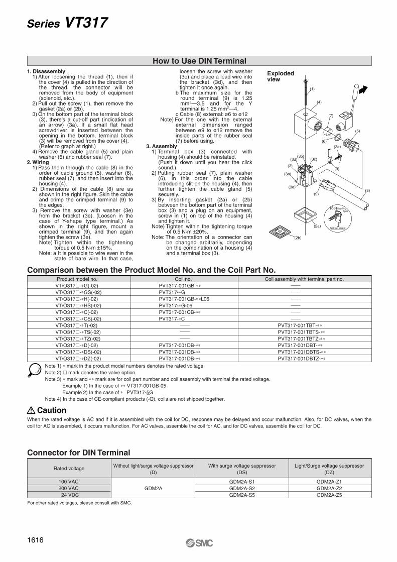
Comparison between the Product Model No. and the Coil Part No.
3
12
1. Disassembly1) After loosening the thread (1), then if
the cover (4) is pulled in the direction of the thread, the connector will be removed from the body of equipment (solenoid, etc.).
2) Pull out the screw (1), then remove the gasket (2a) or (2b).
3) On the bottom part of the terminal block (3), there’s a cut-off part (indication of an arrow) (3a). If a small flat head screwdriver is inserted between the opening in the bottom, terminal block (3) will be removed from the cover (4). (Refer to graph at right.)
4) Remove the cable gland (5) and plain washer (6) and rubber seal (7).
2. Wiring1) Pass them through the cable (8) in the
order of cable ground (5), washer (6), rubber seal (7), and then insert into the housing (4).
2) Dimensions of the cable (8) are as shown in the right figure. Skin the cable and crimp the crimped terminal (9) to the edges.
3) Remove the screw with washer (3e) from the bracket (3e). (Loosen in the case of Y-shape type terminal.) As shown in the right figure, mount a crimped terminal (9), and then again tighten the screw (3e).Note) Tighten within the tightening
torque of 0.5 N·m ±15%.Note: a It is possible to wire even in the
state of bare wire. In that case,
loosen the screw with washer (3e) and place a lead wire into the bracket (3d), and then tighten it once again.
b The maximum size for the round terminal (9) is 1.25 mm2—3.5 and for the Y terminal is 1.25 mm2—4.
c Cable (8) external: ø6 to ø12 Note) For the one with the external
external dimension ranged between ø9 to ø12 remove the inside parts of the rubber seal (7) before using.
3. Assembly1) Terminal box (3) connected with
housing (4) should be reinstated.(Push it down until you hear the click sound.)
2) Putting rubber seal (7), plain washer (6), in this order into the cable introducing slit on the housing (4), then further tighten the cable gland (5) securely.
3) By inserting gasket (2a) or (2b) between the bottom part of the terminal box (3) and a plug on an equipment, screw in (1) on top of the housing (4) and tighten it.
Note) Tighten within the tightening torque of 0.5 N·m ±20%.
Note: The orientation of a connector can be changed arbitrarily, depending on the combination of a housing (4) and a terminal box (3).
Magnifying figure
Self-up screw
(1)
(3)
(4)
(5)
(6)
(7)
(9)
(9)(8)
Exploded view
(2a)
(2b)
(3e)
(3a)
(3e)
(3d)(3b)
(3c)
(3e)
Note 1) ∗ mark in the product model numbers denotes the rated voltage.Note 2) � mark denotes the valve option.Note 3) ∗ mark and ∗∗ mark are for coil part number and coil assembly with terminal the rated voltage.
Example 1) In the case of ∗∗ VT317-001GB-05Example 2) In the case of ∗ PVT317-5G
Note 4) In the case of CE-compliant products (-Q), coils are not shipped together.
Product model no.VT/O317�-∗G(-02)VT/O317�-∗GS(-02)VT/O317�-∗H(-02)VT/O317�-∗HS(-02)VT/O317�-∗C(-02)VT/O317�-∗CS(-02)VT/O317�-∗T(-02)VT/O317�-∗TS(-02)VT/O317�-∗TZ(-02)VT/O317�-∗D(-02)VT/O317�-∗DS(-02)VT/O317�-∗DZ(-02)
Coil no.PVT317-001GB-∗∗PVT317-∗GPVT317-001GB-∗∗L06PVT317-∗G-06PVT317-001CB-∗∗PVT317-∗C
PVT317-001DB-∗∗PVT317-001DB-∗∗PVT317-001DB-∗∗
Coil assembly with terminal part no.
PVT317-001TBT-∗∗PVT317-001TBTS-∗∗PVT317-001TBTZ-∗∗PVT317-001DBT-∗∗PVT317-001DBTS-∗∗PVT317-001DBTZ-∗∗
CautionWhen the rated voltage is AC and if it is assembled with the coil for DC, response may be delayed and occur malfunction. Also, for DC valves, when the coil for AC is assembled, it occurs malfunction. For AC valves, assemble the coil for AC, and for DC valves, assemble the coil for DC.
Connector for DIN Terminal
Rated voltage Without light/surge voltage suppressor(D)
GDM2A
With surge voltage suppressor(DS)
GDM2A-S1GDM2A-S2GDM2A-S5
Light/Surge voltage suppressor(DZ)
GDM2A-Z1GDM2A-Z2GDM2A-Z5
For other rated voltages, please consult with SMC.
100 VAC200 VAC 24 VDC
How to Use DIN Terminal
1616
Series VT317
P1569-1636-E.qxd 08.9.2 4:01 PM Page 1616
VV061
V100
S070
VQD
VKF
VK
VT
VS
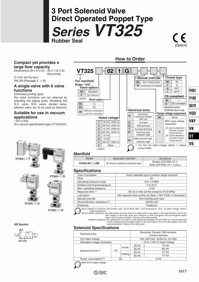
Compact yet provides a large flow capacityDimensions (W x H x D)····55 x 118 x 53 (Grommet)C: 0.61 dm3/(s·bar){Rc 3/8 (Passage 2 → 3)}
A single valve with 6 valve functions(Universal porting type)Six valve functions can be attained by selecting the piping ports. (Enabling the N.C. valve, N.O. valve, divider valve, selector valve, etc. to be used as desired.)
Suitable for use in vacuum applications–101.2 kPa(For vacuum specifications type: VT/VO325V)
VT325
For manifold: Enter “VO”.
02 1 G
JIS Symbol
VT325-��T
VT325-��D
VT325-��C
VT325-��G
Q ∗
Fluid
Ambient and fluid temperatureMax. operating frequency
LubricationManual overrideShock/Vibration resistance (2) Enclosure
Air
5 to 50°C
Type of actuation Direct operated type 2 position single solenoid
Operating pressure range 0 to 1.0 MPa
5 Hz
Not required (Use turbine oil Class 1 ISO VG32, if lubricated.)Response time (1) 30 ms or less (at the pressure of 0.5 MPa)
Non-locking push type150/50 m/s2
DustproofNote 1) Based on dynamic performance test, JIS B 8374-1981. (Coil temperature: 20°C, at rated voltage, without
surge suppressor)Note 2) Impact resistance: No malfunction occurred when it is tested with a drop tester in the axial direction and at the
right angles to the main valve and armature in both energized and de-energized states every once for each condition. (Values at the initial period)
Vibration resistance: No malfunction occurred in a one-sweep test between 45 and 1000 Hz. Test was performed at both energized and de-energized states in the axial direction and at the right angles to the main valve and armature. (Values at the initial period)
Solenoid Specifications
Specifications
Manifold
Electrical entry
Coil rated voltageAllowable voltage fluctuation
Apparent power (3)
Power consumption (3)
AC
DC
50 Hz60 Hz50 Hz60 Hz
Inrush
Holding
Grommet, Conduit, DIN terminal,Conduit terminal
100, 200 VAC, 50/60 Hz, 24 VDC–15 to +10% of rated voltage
75 VA60 VA27 VA17 VA
12 WNote 3) At rated voltage
Model
VO325-00��(-Q)
Applicable manifold
B mount common exhaust typeGasket (DXT083-13-1)
Bolts (DXT083-19-1, 2 pcs.)
Accessory
∗ Option
Valve optionNilV ∗
StandardFor vacuum
Nil None
S
With surge voltage suppressor
Manual overrideNil Non-locking type
M Locking type (Tool required)
Thread typeNilFNT
RcG
NPTNPTF
Electrical entry
Rated voltage123 ∗
4 ∗
56 ∗
9 ∗7 ∗
100 VAC, 50/60 Hz200 VAC, 50/60 Hz110 VAC, 50/60 Hz220 VAC, 50/60 Hz
24 VDC12 VDC
240 VAC, 50/60 HzOther
∗ Option
G Grommet, Lead wire length
300 mm
C ConduitD DIN terminal
DL∗∗ DIN terminal with indicator light
T Conduit terminalTL∗∗ Terminal with
indicator light
Port size1 4
Without connectionport (For manifold)
00
023 8 03
∗∗ For the coil rated voltage (option ∗), please contact SMC.
AC: Can be attached to Grommet, Conduit, Conduit terminal.
DC: Can be attached to Grommet, Conduit, Conduit terminal.
Surge voltage suppressor
CE-compliant
CE-compliantNil —
∗ Electrical entry: D/DO/DL/DLO only
1617
How to Order
3 Port Solenoid ValveDirect Operated Poppet Type
Series VT325Rubber Seal
[Option]
P1569-1636-E.qxd 08.9.2 4:01 PM Page 1617
Construction
De-energized Energized
123
1618
Series VT325
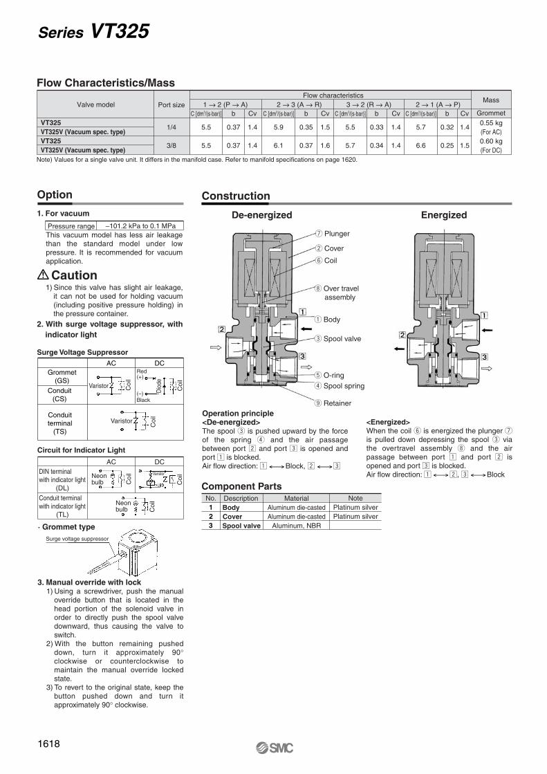
Flow Characteristics/Mass
C [dm3/(s·bar)] b Cv
Mass
GrommetPort size
1/4
3/8
Valve model
VT325VT325V (Vacuum spec. type)VT325VT325V (Vacuum spec. type)
C [dm3/(s·bar)] b Cv C [dm3/(s·bar)] b Cv C [dm3/(s·bar)] b Cv
5.5 0.37 1.4 5.9 0.35 1.5 5.5 0.33 1.4 5.7 0.32 1.4
5.5 0.37 1.4 6.1 0.37 1.6 5.7 0.34 1.4 6.6 0.25 1.5
Flow characteristics1 → 2 (P → A) 2 → 3 (A → R) 3 → 2 (R → A) 2 → 1 (A → P)
0.55 kg(For AC)0.60 kg(For DC)
Note) Values for a single valve unit. It differs in the manifold case. Refer to manifold specifications on page 1620.
1. For vacuum
3. Manual override with lock1) Using a screwdriver, push the manual
override button that is located in the head portion of the solenoid valve in order to directly push the spool valve downward, thus causing the valve to switch.
2) With the button remaining pushed down, turn it approximately 90° clockwise or counterclockwise to maintain the manual override locked state.
3) To revert to the original state, keep the button pushed down and turn it approximately 90° clockwise.
Pressure range –101.2 kPa to 0.1 MPa
Circuit for Indicator Light
ACDIN terminal with indicator light
DC
(DL)
Conduit terminal with indicator light
(TL)
· Grommet type
1) Since this valve has slight air leakage, it can not be used for holding vacuum (including positive pressure holding) in the pressure container.
2. With surge voltage suppressor, with indicator light
Surge Voltage Suppressor
Operation principle<De-energized>The spool e is pushed upward by the force of the spring r and the air passage between port x and port c is opened and port z is blocked.Air flow direction: z Block, x c
<Energized>When the coil y is energized the plunger u is pulled down depressing the spool e via the overtravel assembly i and the air passage between port z and port x is opened and port c is blocked.Air flow direction: z x, c Block
Component PartsNo. Description
BodyCoverSpool valve
MaterialAluminum die-castedAluminum die-casted
Aluminum, NBR
NotePlatinum silverPlatinum silver
Option
ACGrommet
(GS)
Conduit(CS)
Conduitterminal
(TS)
DC
Caution
u Plunger
w Cover
y Coil
i Over travel assembly
q Body
e Spool valve
t O-ringr Spool spring
o Retainer
Coi
l
Coi
l
Dio
deC
oil
Coi
l
Coi
l
Coi
l
Red (+)
(–) Black
Neonbulb
Neonbulb
This vacuum model has less air leakage than the standard model under low pressure. It is recommended for vacuum application.
Varistor
Varistor
Varistor
Surge voltage suppressor
P1569-1636-E.qxd 08.9.2 4:01 PM Page 1618
VV061
V100
S070
VQD
VKF
VK
VT
VS
Grommet (G)
DIN terminal (D)
Conduit (C)
Conduit terminal (T)
With locking manual override Conduit terminal with indicator light (TL)
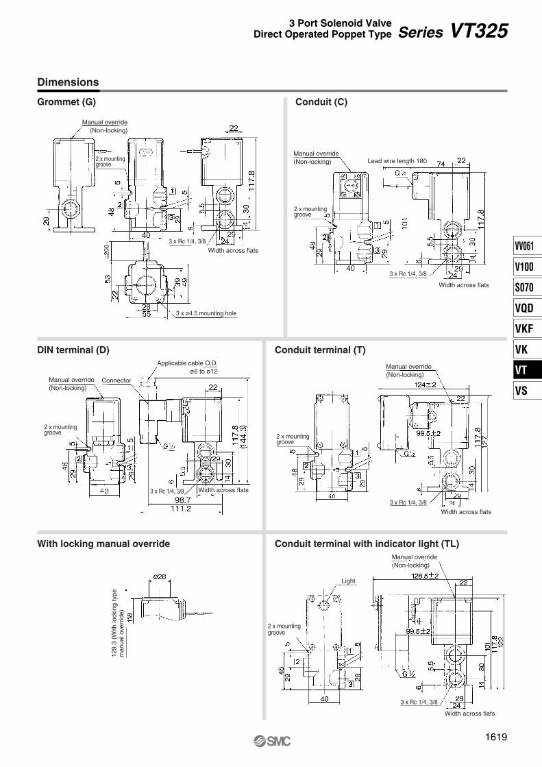
Dimensions
1619
Series VT3253 Port Solenoid ValveDirect Operated Poppet Type
Manual override(Non-locking)
2 x mounting groove
3 x Rc 1/4, 3/8
3 x Rc 1/4, 3/8
Width across flats
≅200
Width across flats
3 x ø4.5 mounting hole
2 x mounting groove
Connector
Manual override(Non-locking)
Applicable cable O.D.ø6 to ø12
129.
3 (W
ith lo
ckin
g ty
pem
anua
l ove
rrid
e)
Light
2 x mounting groove
Manual override(Non-locking)
3 x Rc 1/4, 3/8
Width across flats
2 x mounting groove
3 x Rc 1/4, 3/8
Width across flats
Manual override(Non-locking)
Manual override(Non-locking)
3 x Rc 1/4, 3/8
Width across flats
Lead wire length 180
2 x mounting groove
P1569-1636-E.qxd 08.9.2 4:01 PM Page 1619

How to Order Manifold
Common exhaust
10VVT34 05
Note) If there are more than 4 stations, supply air from both P ports and exhaust from both R ports.
PrecautionsWarning
Changing from N.C. to N.O.Caution
The valves are assembled as N.C. valves at the time of shipment.By removing the two retaining screws from the desired valves, and rotating each valve body 180° and reassembling it on the manifold base, it is possible to reassemble an N.C. valve as an N.O. valve. (When doing so, make sure that a gasket is attached to the mounting surface of the valve.) Properly tighten the screws. The tightening torque of the retaining screws is 3 N·m.
When mounting valves on the manifold base, the mounting orientation is decided. If it is mounted in the wrong direction, connected equipment may malfunction. Mount it by referring to external dimensions on page 1621. Besides, the external dimensions are showing the case of N.C. specifications.
Manifold Specifications
Series VT325 Manifold Model has a B mount style with common exhaust.
∗ Instruct by specifying the valves and blanking plate to be mounted on the manifold along with the manifold base model no. <Example>VVT340-051········ 1 pc.VO325-001G······· 4 pcs.DXT083-21A········1 pc.
Manifold type
DXT083-21A
Max. number of stationsApplicable solenoid valve
B mount17 stations Note)
VO325-00��(-Q)
Exhaust port type
Common
Port location/Port size Port directionP
Side
A
Side/Bottom
R
Side
ABase
1 4 3 8,
PBase
1 4 3 8,
RBase
1 4 3 8,
Exhaust port type1 Common exhaust
Valve stations
Porting specifications
R
SideSide
A
BottomSide
P
SideSide
Symbol
10
2 stations
17 stations
02
17
02Symbol Port size
1 403 3 8
Port sizeThread typeNilFNT
RcG
NPTNPTF
Flow Characteristics/Mass
C [dm3/(s·bar)] b Cv
Mass
GrommetValve model
VO325
VO325V (Vacuum spec. type)
C [dm3/(s·bar)] b Cv C [dm3/(s·bar)] b Cv C [dm3/(s·bar)] b Cv
4.1 0.24 1.0 4.4 0.18 1.0 4.5 0.15 1.0 4.3 0.23 1.0
Flow characteristics1 → 2 (P → A) 2 → 3 (A → R) 3 → 2 (R → A) 2 → 1 (A → P)
0.58 kg(For AC)0.63 kg
(For DC)
Accessory for Applicable Description
Manifold gasketPart no.
DXT083-13-1Qty.1 pc.
Hexagon socket head screw DXT083-19-1 2 pcs.
··· ···
Option Blanking plate (With gasket, screw)
1620
Series VT325Manifold Specifications
P1569-1636-E.qxd 08.9.2 4:01 PM Page 1620
VV061
V100
S070
VQD
VKF
VK
VT
VS
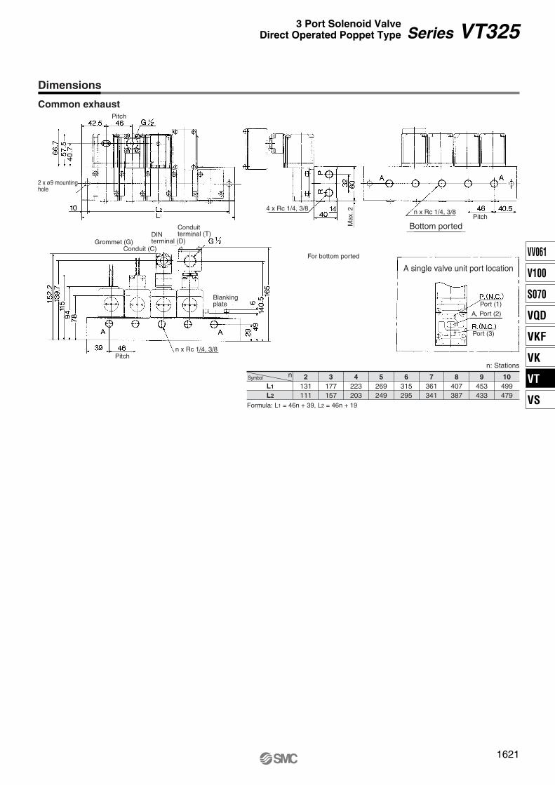
Dimensions
Common exhaust
1621
Series VT3253 Port Solenoid ValveDirect Operated Poppet Type
nSymbol
L1
L2
2131111
3177157
4223203
5269249
6315295
7361341
8407387
9453433
10499479
n: Stations
Formula: L1 = 46n + 39, L2 = 46n + 19
Pitch
2 x ø9 mounting hole
Blankingplate
Pitchn x Rc 1/4, 3/8
Grommet (G)Conduit (C)
DINterminal (D)
Conduitterminal (T)
For bottom ported
4 x Rc 1/4, 3/8 n x Rc 1/4, 3/8
Bottom portedPitch
A single valve unit port location
Port (1)
A, Port (2)
Port (3)
Max
. 2
P1569-1636-E.qxd 08.9.2 4:01 PM Page 1621

Caution1. The bottom of the solenoid valve has a
breather hole for the main valve. Take proper measures to prevent this hole from being blocked as this will lead to a malfunction.
∗ Ordinarily, when the solenoid valve is mounted on a metal surface, it can breathe through the breather hole, via the breather groove. However, in particular, if the surface to be mounted is made of the rubber, the rubber could deform and block the hole.
2. Make sure that dust and/or other foreign materials do not enter the valve from the unused port (e.g. exhaust port).The grommet portion contains a breather hole for the core. Take proper measures to prevent dust or foreign matter from accumulating in this area.
Electrical Connection
Connector for DIN Terminal
DescriptionDIN connector
Part no.GDM2C
1622
How to Wire DIN Terminal
Series VT325Specific Product PrecautionsBe sure to read before handling. Refer to front matters 58 and 59 for Safety Instructions and pages 3 to 7 for 3/4/5 Port Solenoid Valve Precautions.
1. Disassembly1) After loosening the thread (1), then if
the cover (4) is pulled in the direction of the thread, the connector will be removed from the body of equipment (solenoid, etc.).
2) Pull the screw (1), and then remove gasket (2a) or (2b).
3) On the bottom part of the terminal block (3), there’s a cut-off part (indication of an arrow) (3a). If a small flat head screwdriver is inserted between the opening in the bottom, terminal block (3) will be removed from the cover (4). (Refer to the figure below.)
4) Remove the cable gland (5) and plain washer (6) and rubber seal (7).
2. Wiring1) Pass them through the cable (8) in
the order of cable ground (5), washer (6), rubber seal (7), and then insert into the housing (4).
2) Dimensions of the cable (8) are the figure as below. Skin the cable and crimp the crimped terminal (9) to the edges.
3) Remove the screw with washer (3e) from the bracket (3e). (Loosen in the case of Y shape type terminal.) As shown in the below figure, mount a crimped terminal (9), and then again tighten the screw (3e).Note) Tighten within the tightening
torque of 0.5 N·m ±15%.Note: a It is possible to wire even in
the state of bare wire. In that case, loosen the screw with washer (3e) and place a lead wire into the bracket (3d), and then tighten it once again.
b The maximum size for the round terminal (9) is 1.25 mm2—3.5 and for the Y terminal is 1.25 mm2—4.
c Cable (8) external: ø6 to ø12Note) For the one with the external
dimension ranged between ø9 to ø12 remove the inside parts of the rubber seal (7) before using.
3. Assembly1) Terminal box (3) connected with
housing (4) should be reinstated. (Push it down until you hear the click sound.)
2) Putting rubber seal (7), plain washer (6), in this order into the cable introducing slit on the housing (4), then further tighten the cable gland (5) securely.
3) By inserting gasket (2a) or (2b) between the bottom part of the terminal box (3) and a plug on an equipment, screw in (1) on top of the housing (4) and tighten it.Note) Tighten within the tightening
torque of 0.5 N·m ±20%.Note: The orientation of a connector
can be changed arbitrarily, depending on the combination of a housing (4) and a terminal box (3).
How to Calculate the Flow RateFor obtaining the flow rate, refer to front matters 44 to 47.
For wiring to DIN terminal, connect the positive (+) polar side with connector terminal no. 1 and the negative (–) side with connector terminal no. 2 when the rated voltage is DC type.
Magnifying figure
Self-up screw3
12
(1)
(3)
(4)
(5)
(6)
(7)
(8)
(9)
(9)
Exploded view
(3e)
(3d)(3d)
(3c)
(3a)
(3e)
(3e)
(2a)
(2b)
Grommet
Bleed groove Bleed port
on main valve
Bottom of the solenoid valve
P1569-1636-E.qxd 08.9.2 4:01 PM Page 1622
Recommended