IM1300YS 07/17
Installation Information
Water Piping Connections
Hot Water Generator Connections
Electrical
Startup Procedures
Troubleshooting
Preventive Maintenance
Syn
erg
y3
D In
stalla
tio
n M
an
ual
Geothermal Heat Pump with Water Heating for Radiant Floor Applications • R-410A Refrigerant
• 3, 4, 5, 6 Ton Dual Capacity
Syn
erg


3
SYNERGY3D INSTALLATION MANUAL
Table of Contents
Model Nomenclature . . . . . . . . . . . . . . . . . . . . . . . . . . . . . . . . . . . . . . . . . . . . . . . . . . . . . . . . . . . . . . . . . . . .4
General Installation Information . . . . . . . . . . . . . . . . . . . . . . . . . . . . . . . . . . . . . . . . . . . . . . . . . . . . . . . . . . 5
Closed Loop Ground Source Systems . . . . . . . . . . . . . . . . . . . . . . . . . . . . . . . . . . . . . . . . . . . . . . . . . . . . .9
Open Loop Ground Water Systems . . . . . . . . . . . . . . . . . . . . . . . . . . . . . . . . . . . . . . . . . . . . . . . . . . . . . . 10
Hot Water Generator Connections . . . . . . . . . . . . . . . . . . . . . . . . . . . . . . . . . . . . . . . . . . . . . . . . . . . . . . . .11
Typical Buffer Tank Installation . . . . . . . . . . . . . . . . . . . . . . . . . . . . . . . . . . . . . . . . . . . . . . . . . . . . . . . . . . .11
Hydronic Section . . . . . . . . . . . . . . . . . . . . . . . . . . . . . . . . . . . . . . . . . . . . . . . . . . . . . . . . . . . . . . . . . . . . . . 12
Electrical Connections . . . . . . . . . . . . . . . . . . . . . . . . . . . . . . . . . . . . . . . . . . . . . . . . . . . . . . . . . . . . . . . . . 14
Electronic Thermostat Installation . . . . . . . . . . . . . . . . . . . . . . . . . . . . . . . . . . . . . . . . . . . . . . . . . . . . . . . 15
Auxiliary Heat . . . . . . . . . . . . . . . . . . . . . . . . . . . . . . . . . . . . . . . . . . . . . . . . . . . . . . . . . . . . . . . . . . . . . . . . . 16
Electrical and Blower Performance Data . . . . . . . . . . . . . . . . . . . . . . . . . . . . . . . . . . . . . . . . . . . . . . . . . 17
Dimensional Data . . . . . . . . . . . . . . . . . . . . . . . . . . . . . . . . . . . . . . . . . . . . . . . . . . . . . . . . . . . . . . . . . . . . . . 18
Physical Data. . . . . . . . . . . . . . . . . . . . . . . . . . . . . . . . . . . . . . . . . . . . . . . . . . . . . . . . . . . . . . . . . . . . . . . . . .20
Microprocessor Control . . . . . . . . . . . . . . . . . . . . . . . . . . . . . . . . . . . . . . . . . . . . . . . . . . . . . . . . . . . . . . . . 21
Operation Logic . . . . . . . . . . . . . . . . . . . . . . . . . . . . . . . . . . . . . . . . . . . . . . . . . . . . . . . . . . . . . . . . . . . . . . .25
Wiring Schematics. . . . . . . . . . . . . . . . . . . . . . . . . . . . . . . . . . . . . . . . . . . . . . . . . . . . . . . . . . . . . . . . . . . . .26
Unit Startup. . . . . . . . . . . . . . . . . . . . . . . . . . . . . . . . . . . . . . . . . . . . . . . . . . . . . . . . . . . . . . . . . . . . . . . . . . .30
Operating Parameters. . . . . . . . . . . . . . . . . . . . . . . . . . . . . . . . . . . . . . . . . . . . . . . . . . . . . . . . . . . . . . . . . . 31
Pressure Drop . . . . . . . . . . . . . . . . . . . . . . . . . . . . . . . . . . . . . . . . . . . . . . . . . . . . . . . . . . . . . . . . . . . . . . . . .32
Compressor and Thermistor Resistance . . . . . . . . . . . . . . . . . . . . . . . . . . . . . . . . . . . . . . . . . . . . . . . . . .33
Heat of Extraction/Rejection. . . . . . . . . . . . . . . . . . . . . . . . . . . . . . . . . . . . . . . . . . . . . . . . . . . . . . . . . . . .34
Antifreeze Corrections . . . . . . . . . . . . . . . . . . . . . . . . . . . . . . . . . . . . . . . . . . . . . . . . . . . . . . . . . . . . . . . . .35
Correction Factor Tables . . . . . . . . . . . . . . . . . . . . . . . . . . . . . . . . . . . . . . . . . . . . . . . . . . . . . . . . . . . . . . .36
Operating Limits, Reference Calculations, Legend and Notes . . . . . . . . . . . . . . . . . . . . . . . . . . . . . . . 37
Troubleshooting . . . . . . . . . . . . . . . . . . . . . . . . . . . . . . . . . . . . . . . . . . . . . . . . . . . . . . . . . . . . . . . . . . . . . . .38
Startup and Troubleshooting Form . . . . . . . . . . . . . . . . . . . . . . . . . . . . . . . . . . . . . . . . . . . . . . . . . . . . . .39
Heating and Cooling Analysis . . . . . . . . . . . . . . . . . . . . . . . . . . . . . . . . . . . . . . . . . . . . . . . . . . . . . . . . . . 40
Hot Water Cycle Analysis . . . . . . . . . . . . . . . . . . . . . . . . . . . . . . . . . . . . . . . . . . . . . . . . . . . . . . . . . . . . . . . 41
Preventative Maintenance and Replacement Procedures . . . . . . . . . . . . . . . . . . . . . . . . . . . . . . . . . . .42
Service Parts List . . . . . . . . . . . . . . . . . . . . . . . . . . . . . . . . . . . . . . . . . . . . . . . . . . . . . . . . . . . . . . . . . . . . . .43
Revision Guide . . . . . . . . . . . . . . . . . . . . . . . . . . . . . . . . . . . . . . . . . . . . . . . . . . . . . . . . . . . . . . . . . . . . . . . 44

4
SYNERGY3D INSTALLATION MANUAL
Model Nomenclature

5
SYNERGY3D INSTALLATION MANUAL
Filter Rack ConversionA 2 in. MERV 11 filter is shipped with the heat pump. To
field convert the filter rack to use 1 in. filters, simply insert
the provided plastic push pins into the holes located in the
filter rack. There are holes on the top and bottom of the
rack, underneath the instruction labels, for field conversion
to 1 in. filters.
Setting Vertical UnitsPrior to setting the unit in place, remove and discard the
compressor hold down shipping bolt located at the front of
the compressor mounting bracket.
Vertical units are available in left or right hand return
configuration. Vertical units should be mounted level on
a vibration absorbing pad slightly larger than the base to
provide isolation between the unit and the floor. It is not
necessary to anchor the unit to the floor (See Vertical Unit
Mounting illustration).
Duct SystemAn air outlet collar is provided on vertical top flow units
to facilitate a duct connection, which is shipped inside the
unit. A flexible connector is recommended for discharge
and return air duct connections on metal duct systems.
Uninsulated duct should be insulated with a minimum of
1 in. duct insulation. Application of the unit to uninsulated
ductwork in an unconditioned space is not recommended
as the unit’s performance will be adversely affected.
If the unit is connected to existing ductwork, a previous
check should have been made to assure that the duct
has the capacity to handle the air required for the unit
application. If ducting is too small, as in the replacement of
heating only systems, larger ductwork should be installed.
All existing ductwork should be checked for leaks and
repaired when necessary.
Moving and StorageMove units in the normal “Up” orientation. Vertical units
are not to be moved, but may be stored one upon another
to a maximum height of two units. When the equipment is
received, all items should be carefully checked against the
bill of lading to be sure all crates and cartons have been
received. Examine units for shipping damage, removing
the units from the packaging if necessary. Units in question
should also be internally inspected. If any damage is noted,
the carrier should make the proper notation on the delivery
receipt, acknowledging the damage.
Unit LocationLocate the unit in an indoor area that allows easy removal
of the filter and access panels, and has enough space
for service personnel to perform maintenance or repair.
Provide sufficient room to make water, electrical and duct
connection(s). If the unit is located in a confined space,
such as a closet, provisions must be made for return air
to freely enter the space by means of a louvered door,
etc. Care should be taken when units are located in unconditioned spaces to prevent damage from frozen water lines and excessive heat that could damage electrical components.
Safety ConsiderationsInstallation and servicing of heating and air conditioning
equipment can be hazardous due to system pressure and
electrical components. Only trained and qualified service
personnel should install, repair or service heating and air
conditioning equipment.
Untrained personnel can perform basic maintenance
functions of cleaning coils and cleaning and replacing
filters. All other operations should be performed by trained
service personnel. When working on air conditioning
equipment, observe precautions in the literature, tags and
labels attached to the unit and other safety precautions
that may apply.
Follow all safety codes. Wear safety glasses and work
gloves. Use quenching cloth for brazing operations. Have
fire extinguisher available for all brazing operations.
WARNING: Before performing service or
maintenance operations on the system, turn off
main power switches to the unit. Turn off accessory
heater power switch if applicable. Electrical shock
could cause serious personal injury.
CAUTION: A minimum of 24 in. clearance should
be allowed for access to front access panel.
Vibration AbsorbingMesh
Air Pad
Vertical Unit Mounting
General Installation Information
6
SYNERGY3D INSTALLATION MANUAL
The duct system should be sized to handle the design
airflow quietly. To maximize sound attenuation of the unit
blower, the supply and return plenums should include inter-
nal duct liner of glass fiber or be of ductboard construction
for the first few feet. If air noise or excessive airflow is a
problem, the blower speed can be changed. See the Blower
Performance and Blower Speed sections.
Water PipingThe proper water flow must be provided to each unit
whenever the unit operates. To assure proper flow, use
pressure/temperature ports to determine the flow rate.
These ports should be located at the supply and return
water connections on the unit. The proper flow rate cannot
be accurately set without measuring the water pressure drop
through the refrigerant-to-water heat exchanger.
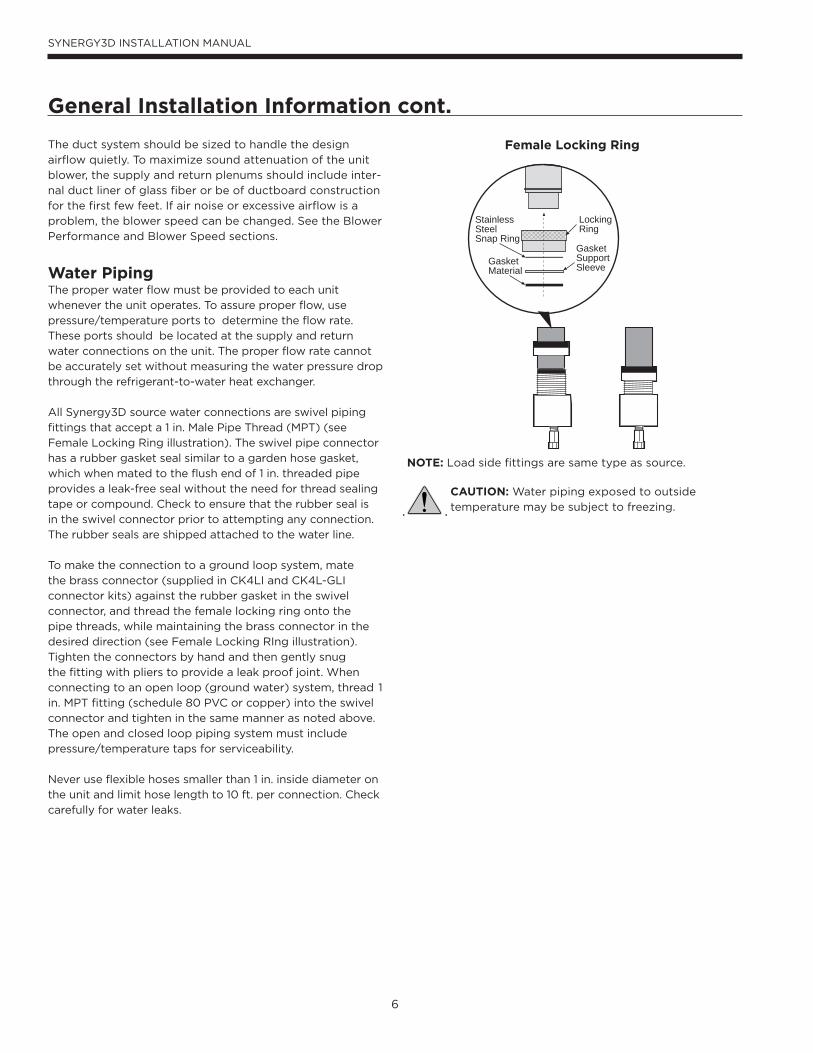
All Synergy3D source water connections are swivel piping
fittings that accept a 1 in. Male Pipe Thread (MPT) (see
Female Locking Ring illustration). The swivel pipe connector
has a rubber gasket seal similar to a garden hose gasket,
which when mated to the flush end of 1 in. threaded pipe
provides a leak-free seal without the need for thread sealing
tape or compound. Check to ensure that the rubber seal is
in the swivel connector prior to attempting any connection.
The rubber seals are shipped attached to the water line.
To make the connection to a ground loop system, mate
the brass connector (supplied in CK4LI and CK4L-GLI
connector kits) against the rubber gasket in the swivel
connector, and thread the female locking ring onto the
pipe threads, while maintaining the brass connector in the
desired direction (see Female Locking RIng illustration).
Tighten the connectors by hand and then gently snug
the fitting with pliers to provide a leak proof joint. When
connecting to an open loop (ground water) system, thread 1
in. MPT fitting (schedule 80 PVC or copper) into the swivel
connector and tighten in the same manner as noted above.
The open and closed loop piping system must include
pressure/temperature taps for serviceability.
Never use flexible hoses smaller than 1 in. inside diameter on
the unit and limit hose length to 10 ft. per connection. Check
carefully for water leaks.
LockingRing
StainlessSteelSnap Ring
GasketSupportSleeveGasket
Material
Female Locking Ring
NOTE: Load side fittings are same type as source.
CAUTION: Water piping exposed to outside
temperature may be subject to freezing.
General Installation Information cont.

7
SYNERGY3D INSTALLATION MANUAL
Water QualityIt is the responsibility of the system designer and installing contractor to ensure that acceptable water quality is present and that all applicable codes have been met in these installations. Failure to adhere to the guidelines in the water quality table could result in loss of warranty. In ground water situations where scaling could be heavy or where biological growth such as iron bacteria will be present, a closed loop system is recommended. The heat exchanger coils in ground water systems may, over a period of time, lose heat exchange capabilities due to a buildup of mineral deposits inside. These can be cleaned, but only by a qualified service mechanic, as special solutions and pumping equipment are required. Hot water generator coils can likewise become scaled and possibly plugged. In areas with extremely hard water, the owner should be informed that the heat exchanger may require occasional flushing.
Units with cupronickel heat exchangers are recommended for open loop applications due to the increased resistance to build-up and corrosion, along with reduced wear caused by acid cleaning. Failure to adhere to the guidelines in the
water quality table could result in the loss of warranty.
Water TreatmentDo not use untreated or improperly treated water. Equip-ment damage may occur. The use of improperly treated or untreated water in this equipment may result in scaling, erosion, corrosion, algae or slime. Purchase of a pre-mix antifreeze could significantly improve system reliability if the water quality is controlled and there are additives in the mixture to inhibit corrosion. There are many examples of such fluids on the market today such as Environol™ 1000
Material Copper 90/10 Cupronickel 316 Stainless SteelpH Acidity/Alkalinity 7 - 9 7 - 9 7 - 9
ScalingCalcium and
Magnesium Carbonate(Total Hardness)
less than 350 ppm(Total Hardness)
less than 350 ppm(Total Hardness)
less than 350 ppm
Corrosion
Hydrogen SulfideLess than 0.5 ppm (rotten egg
smell appears at 0.5 ppm)10 - 50 ppm Less than 1 ppm
Sulfates Less than 125 ppm Less than 125 ppm Less than 200 ppm
Chlorine Less than 0.5 ppm Less than 0.5 ppm Less than 0.5 ppm
Chlorides Less than 20 ppm Less than 125 ppm Less than 300 ppm
Carbon Dioxide Less than 50 ppm 10 - 50 ppm 10 - 50 ppm
Ammonia Less than 2 ppm Less than 2 ppm Less than 20 ppm
Ammonia Chloride Less than 0.5 ppm Less than 0.5 ppm Less than 0.5 ppm
Ammonia Nitrate Less than 0.5 ppm Less than 0.5 ppm Less than 0.5 ppm
Ammonia Hydroxide Less than 0.5 ppm Less than 0.5 ppm Less than 0.5 ppm
Ammonia Sulfate Less than 0.5 ppm Less than 0.5 ppm Less than 0.5 ppm
Total Dissolved Solids (TDS) Less than 1000 ppm 1000 - 1500 ppm 1000 - 1500 ppm
LSI Index +0.5 to -0.5 +0.5 to -0.5 +0.5 to -0.5
Iron Fouling(Biological Growth)
Iron, FE2+ (Ferrous)Bacterial Iron Potential
< 0.2 ppm < 0.2 ppm < 0.2 ppm
Iron OxideLess than 1 ppm, above this level deposition will occur
Less than 1 ppm, above this level deposition will occur
Less than 1 ppm, above this level deposition will occur
ErosionSuspended Solids
Less than 10 ppm and filtered for max. of 600 micron size
Less than 10 ppm and filtered for max. of 600 micron size
Less than 10 ppm and filtered for max. of 600 micron size
Threshold Velocity(Fresh Water)
< 6 ft/sec < 6 ft/sec < 6 ft/sec
NOTES: Grains = ppm divided by 17 mg/L is equivalent to ppm
2/22/12
(pre-mix ethanol), and others. The services of a qualified water treatment specialist should be engaged to determine what treatment, if any, is required. The product warranty specifically excludes liability for corrosion, erosion or dete-rioration of equipment.The heat exchangers and water lines in the units are copper or cupronickel tube. There may be other materials in the buildings piping system that the designer may need to take into consideration when deciding the parameters of the water quality. If antifreeze or water treatment solution is to be used, the designer should confirm it does not have a detrimental effect on the materials in the system.
Contaminated WaterIn applications where the water quality cannot be held to prescribed limits, the use of a secondary or intermediate heat exchanger is recommended to separate the unit from the contaminated water. The table above outlines the water quality guidelines for unit heat exchangers. If these condi-tions are exceeded, a secondary heat exchanger is re-quired. Failure to supply a secondary heat exchanger where needed will result in a warranty exclusion for primary heat exchanger corrosion or failure.
General Installation Information cont.

8
SYNERGY3D INSTALLATION MANUAL
General Installation Information cont.
Freeze Detection Limit (Water Flow)Set the freeze detection limit switch SW2 #2 to “Loop” on
the printed circuit board for applications using a closed
loop antifreeze solution. On applications using an open
loop/ground water system, set to “Well” (the factory
setting). If using closed loop and no antifreeze solution
leave in “Well” position (the factory setting).
Condensate DrainThe internal condensate drain assembly consists of a drain
tube, which is attached to the drain pan, a 3/4 in. PVC
female adapter, and a flexible connecting hose. The female
adapter may exit either the front or the side of the vertical
cabinet. The adapter will be glued to the field-installed
PVC condensate piping. A condensate hose is inside all
cabinets as a trapping loop; therefore, an external trap is
not necessary.

9
SYNERGY3D INSTALLATION MANUAL
Closed Loop Ground Source Systems
Once piping is completed between the unit, flow center
and the ground loop, final purging and charging of the
loop is needed. A flush cart (at least a 1.5 HP pump) is
needed to achieve adequate flow velocity in the loop to
purge air and dirt particles from the loop itself. Antifreeze
solution is used in most areas to prevent freezing. Flush
the system adequately to remove as much air as possible
then pressurize the loop to a static pressure of 50-75 psi
(winter) or 40-50 psi (summer). This is normally adequate
for good system operation. Loop static pressure will
fluctuate with the seasons. Pressures will be higher in
the winter months than during the cooling season. This
fluctuation is normal and should be considered when
charging the system initially.
After pressurization, be sure to burp the pump. Open
the screw 2 turns only in the end of the pump motor (if
Grundfos® pumps are used) to allow trapped air to be
discharged and to ensure the motor housing has been
flooded. Ensure the loop flow center provides adequate
Closed Loop: Ground Source Application
FlexibleDuctCollar
Vibration Absorbing Pad
P/T Plugs
LPK
Drain
Connector Kits with Armaflex
Disconnects(If Applicable)
GeoLinkPolyethylene w/
Armaflex
TOLOOP
AuxiliaryHeaterKnockout
LowVoltage to
Thermostat Unit Power
Unit Supply
AuxiliaryHeat Supply
* For complete information, refer to GeoLink® Flow Center Installation Manual
GeoLinkFlow
Center*
ExternalPumpPower
flow through the unit by checking pressure drop across the
heat exchanger (Refer to Pressure Drop table). Usually 2.5-
3 gpm of flow per ton of cooling capacity is recommended
in earth loop applications. Refer to Wiring Schematics for
loop pump power wiring details.
Multiple Units on One Flow CenterWhen two units are connected to one loop pumping
system, pump control is automatically achieved by
connecting the slave terminals on connector P2 in both
units with 2-wire thermostat wire. These terminals are
polarity dependent (see below). The loop pump(s) may be
powered from either unit, whichever is more convenient. If
either unit calls, the loop pump(s) will automatically start.
The use of two units on one flow center is generally limited
to a total of 20 gpm capacity.
It is recommended that water solenoid valves be installed
on heat pumps that share a flow center. This is to allow
water flow through only the heat pump that has a demand.
Circulating fluid through a heat exchanger of a system
that is not operating could be detrimental to the long term
reliability of the compressor
5 or 7 Series toSynergy3DSeries Units
Synergy 3D Unit #1
5 or 7 SeriesUnit #1
with AXB Board
VSSLOSLIOUTIN C C
With pumpwired toUnit 1
With pumpwired toUnit 2
ShutDown C C
SL1In
SL1Out
ShutDown C C SL1
InSL1Out
Synergy3D Unit #1
To Electromechanical Unit
C S
Synergy3D toElectromechanical Units
With pumpwired to Unit 1
With pumpwired toUnit 2
ShutDown C C
ShutDown C C
SL1In
SL1Out
SL1In
SL1Out
Synergy 3D Unit #1
Synergy3D Unit #2
Synergy3D to Synergy3DMicroprocessor Units
Primary/Secondary Hook-up

10
SYNERGY3D INSTALLATION MANUAL
Typical open loop piping is shown in the Open System:
Ground Water Application. Always maintain water pressure
in the heat exchanger by placing water control valves at
the outlet of the unit to prevent mineral precipitation. Use
a closed, bladder-type expansion tank to minimize mineral
formation due to air exposure. Ensure proper water flow
through the unit by checking pressure drop across the heat
exchanger and comparing it to the figures in the pressure
drop tables. Normally about 2 GPM flow rate per ton of
cooling capacity (1.5 GPM per ton minimum at 50° F) is
needed in open loop systems.
Open Loop Ground Water Systems
NOTES: For open loop ground water systems or systems
that do not contain and antifreeze solution, set SW2-#2 to
the “Well” position.
Open System: Ground Water Application
Flexible DuctCollar
VibrationAbsorbing Pad
Drain
Disconnects(If Applicable)
AuxiliaryHeaterKnockout
UnitSupply
Aux. HeatSupply
Rubber BladderExpansion Tank
Boiler DrainsFor HX Flushing
StrainerLow Voltage
to Thermostatand Valve
UnitPower
Shut Off Valves(to isolate solenoidvalve while acid flushing)
Shut Off Valves
Water Out
Water In
SolenoidValve
Flow Control Valve(on outlet of
Solenoid Valve)
P/T Plugs
Discharge water from the unit is not contaminated in any
manner and can be disposed of in various ways such as
recharge well, storm sewer, drain field, adjacent stream or
pond, etc. depending on local building codes. Most local
codes forbid the use of sanitary sewer for disposal. Consult
your local building and zoning department to ensure
compliance in your area.
Open Loop Solenoid Valve Connection OptionTypical slow operating external 24V water solenoid valve(type V) wiring.
C
R
C
W/Y
V ValveCC
Open Loop Solenoid Valve Connection OptionTypical quick operating external 24V water solenoid valve(type PPV100 or BPV100) wiring.
C
RP1
SV
SolenoidValve
CC
Open Loop Solenoid Valve Connection Option: Wiring
diagram for dual water valve installations, one type V
slow operating solenoid and one BPV100/PPV100 quick
operating solenoid.
C
W/Y
CCG or CC GND
CC
CC
U
SV CC2 or CCHI
Logic BoardTaco ValveV100FPT(Type V)
BPV/PPV Solenoid
Compressor Contactor
Coil

11
SYNERGY3D INSTALLATION MANUAL
WaterFurnaceSynergy3D
GEOSTORAGE
TANK
LOAD PUMP
HYDRONICLOAD
DielectricUnions
80 or 120 gal. Geothermal Storage Tankfor hydronic load
DielectricUnions
1-1/2˝FPT
ExpansionTank
AirVent
PressureGauge
30 PSIRELIEF VALVE
AirSeparator
P/T Ports
80 gal. water heater tankfor domestic hot water
Back Flow Preventer /Pressure Reducing Valve
*NOTE: A 30 PSI pressure relief valve (Part No: SRV30) should be used in hydronic applications.
Ball Valve
COLD3/4˝ Domestic
HOT3/4˝ Domestic
1-1/2˝FPT
1˝ Connections
DPK5
Typical Buffer Tank Installation
Synergy3D with Hydronic Storage Tank and Domestic Water Heater Tank
To maximize the benefits of the hot water generator a
minimum 50-gallon water heater is recommended. For
higher demand applications, use an 80-gallon water heater
as shown below or two 50-gallon water heaters connected
in a series. Electric water heaters are recommended. Make
sure all local electrical and plumbing codes are met for
installing a hot water generator. The Synergy3D is not
supplied with an internal circulator. A DPK5 kit will need
to be purchased to connect to the hot water generator.
Unit ModelCopper I.D. Pipe Size
(in)Flow Rates (GPM)
Maximum Feet of Pipe One Way
Total Number of Elbows
Recommended Storage Tank Size
SDV038 1.25 9 30’ 10 80 U.S. Gals
SDV049 1.25 12 30’ 10 80 U.S. Gals
SDV064 1.25 15 30’ 10 120 U.S. Gals
SDV072 1.50 18 30’ 10 120 U.S. Gals
Synergy3D Hydronic Storage Tank Recommendations
Hot Water Generator Connections
The DPK5 kit is supplied with installation instructions,
circulator, tank adaptor and temperature limit switch.
Be sure to burp the pump. Open the screw 2 turns only
in the end of the pump motor (if Grundfos® pumps are
used) to allow trapped air to be discharged and to ensure
the motor housing has been flooded. A water softener is
recommended with hard water (greater than 10 grains or
170 ppm total hardness).

12
SYNERGY3D INSTALLATION MANUAL
General guidelines are shown below for component
selection and design/installation criteria for the piping
system. Local codes supersede any recommendations in
this manual.
Shut off/flow regulation valves: Use full port ball valves or
gate valves for component isolation. If valves are going to
be used frequently, ball valves are recommended. Globe
valves are designed for flow regulation. Always install globe
valves in the correct direction (fluid should enter through
the lower body chamber).
Check valves: Swing check valves must be installed in the
horizontal position with the bonnet of the valve upright.
Spring check valves can be mounted in any position. A flow
check valve is required to prevent thermo-siphoning (or
gravity flow) when the circulator pump is off or when there
are two circulators on the same system.
Storage (Buffer) tank: A buffer tank is required for all
hydronic heating systems using Synergy3D heat pumps.
The tank should be sized to provide 2 gallons of storage
capacity for every one thousand btuh’s of nominal heat
pump capacity.
Pressure relief valve: Most codes require the use of a
pressure relief valve if a closed loop heat source can be
isolated by valves. Even if local code does not require
this device, WaterFurnace recommends its installation. If
the pressure relief valve in the buffer tank is not already
rated at 30 psi (207 kPa) maximum pressure, one must be
installed. The pressure relief valve should be tested at start
up for operation. This valve can also be used during initial
filling of the system to purge air. Note that the waste pipe
must be at least the same diameter as the valve outlet
(never reduce), and valves may not be added to this pipe.
The bottom of the pipe must terminate at least 6” (15 cm)
above the floor. If the piping is connected to a drain, there
must be an air gap.
Backflow prevention check valves: Most codes require
backflow prevention check valves. Note that a single
check valve is not equal to a backflow prevention check
valve. Even if local code does not require this device,
WaterFurnace recommends its installation. This is
particularly important if the system will use antifreeze.
Pressure reducing valves or feed water valves: This valve
lowers the pressure from the make-up water line to the
system. Most are adjustable and directional. A “fast fill”
valve is required for initial filling of the system. Some have
screens, which must be cleaned after the initial filling. If
there is a restriction in the screen, the system could go to
0 psi (0 kPa), potentially causing pumps(s) failure. A valve
should be installed on each side of the pressure reducing
Hydronic Section
valve for servicing. Both valves should have tags reading
“Do not shut this valve under normal operation – service
valve only”.
Expansion tanks: Expansion tanks are required on hydronic
systems to help absorb the pressure swings as the
temperature in the system fluctuates.
Elbows/tees: Long radius elbows or two 45° elbows
will lower pressure drop. Standard tees have a greater
restriction on the “T” portion than tees designed with
angled outlet ports.
Antifreeze: Antifreeze is required if any of the piping
system is located in areas subject to freezing.
Dielectric unions: Dielectric unions are recommended
whenever connecting two dissimilar metals to one and
other to prevent electro-galvanic corrosion.
When using the various types of hydronic heat distribution
systems, the temperature limits of the geothermal system
must be a major consideration. In new construction,
the distribution system can easily be designed with the
temperature limits in mind. In retrofits, care must be
taken to address the operating temperature limits of the
existing distribution system. The maximum storage tank
temperature for the Synergy3D is 130°F (54.4°C). Typical
in floor radiant systems require much lower temperatures,
typically 100°-115°F, which is ideal for the Synergy3D.
The Synergy3D uses an external temperature sensor such
as the lower thermostat in a water heater storage tank to
control the tank temperature. The thermostat should be
wired to the Synergy3D P5 connector wires, P5-11 and P5-4
tan wires. When the tank temperature drops below the
thermostat setting the contacts in the thermostat will close
and initiate a signal to the Synergy3D to heat water.
A storage tank must be used to store the heated water
supplied by the Synergy3D. It is not recommended to send
heated water from the Synergy3D directly to the hydronic
zones since the Synergy3D also has the ability to condition
the space with forced air. There must be adequate storage
capacity in the storage tank to accommodate the hydronic
load while the Synergy3D is operating in forced air mode.
The hydronic storage tank should be sized to provide 2
gallons of storage capacity for every one thousand Btuh’s
of nominal heat pump capacity.
Adequate rate of flow (GPM) is very important to system
performance and long term reliability. Follow the guidelines
for recommended flow and pipe sizing in the Synergy3D
Recommendations table.

13
SYNERGY3D INSTALLATION MANUAL
The unit uses an external temperature sensor such as the lower thermostat in a water heater storage tank to control the tank temperature. The thermostat should be wired to the unit P5 connector wires, P5-11 and P5-4 tan wires. When the tank temperature drops below the thermostat setting the contacts in the thermostat will close and initiate a signal to the unit to heat water.
A storage tank must be used to store the heated water supplied by the unit. It is not recommended to send heated water from the unit directly to the hydronic zones since the unit also has the ability to condition the space with forced air. There must be adequate storage capacity in the storage tank to accommodate the hydronic load while the unit is operating in forced air mode. The hydronic storage tank should be sized to provide 2 gallons of storage capacity for every one thousand Btuh’s of nominal heat pump capacity.
Adequate rate of flow (GPM) is very important to system performance and long term reliability. Follow the guidelines for recommended flow and pipe sizing in the unit recommendations table.
Be sure to burp the pump. Open the screw 2 turns only in the end of the pump motor (if Grundfos® pumps are used) to allow trapped air to be discharged and to ensure the motor housing has been flooded.
The red “courtesy” wires exit out of the top of the Geo Storage tank. The wires must be connected to the tank thermostat and to P5 tan connector wires, P5-11 and P5-4 on the main logic board.
Hydronic Section cont.
WaterFurnace Geothermal Storage Tank Thermostat
Synergy3D must be wired to the thermostat screw terminals. The yellow thermistor wires will not operate with the Synergy3D as they are used with the NSW Series water-to-water.
Thermostat

14
SYNERGY3D INSTALLATION MANUAL
GeneralBe sure the available power is the same voltage and phase
as that shown on the unit serial plate. Line and low voltage
wiring must be done in accordance with local codes or the
National Electric Code, whichever is applicable.
Unit Power ConnectionLine Voltage connection is made by connecting the incoming
line voltage wires to the “L” side of the contactor as shown.
Consult the Electrical Data table for correct fuse size.
External Loop Pump Power ConnectionIf the unit is to be used with an external loop pump (FC1
or FC2 flow center), the pump(s) will be connected to the
terminals on PB1 in the unit electrical box as shown. The
pumps will automatically be cycled as required by the
unit or by a secondary signal from another Synergy3D
unit sharing the flow center. (Refer to the Wiring
Schematics section.)
208 Volt OperationAll 208-230 volt units are factory wired for 230 volt
operation. For 208 volt operation, the red and the blue
transformer wires must be switched on terminal strip PS1.
(Refer to the Wiring Schematics section.)
Synergy3D Line Voltage 208-230/60/1
Electrical Connections
L1L2
PB1
PS1
PS2

15
SYNERGY3D INSTALLATION MANUAL
Electronic Thermostat Installation
Thermostat WiringInstallationPosition the thermostat subbase against the wall so that
it is level and the thermostat wires protrude through the
subbase. Mark the position of the subbase mounting holes
and drill holes with a 3/16 in. bit. Install anchors and secure
base to the wall. Thermostat wire must be 8 conductor 18
AWG wire. Strip the wires back 1/4 in. (longer strip lengths
may cause shorts) and insert the thermostat wires into the
Synergy3D connector as shown in the Thermostat Wiring
diagram. Tighten the screws to ensure good connections.
The thermostat has the same type of connectors, requiring
the same wiring. See instructions enclosed in the thermostat
for detailed installation and operation information.
Other ThermostatsThe Synergy3D unit is compatible with virtually any 24VAC
thermostat. However, the multi-stage nature of this product
requires a 3-stage heating/2-stage cooling type thermostat.
NOTE: DIP switch SW2-8 is required to be in
the “OFF” position for the control to operate
with FaultFlash or ComforTalk thermostats.
SW2-8 in the “ON” position configures the
control to operate with typical thermostats
(continuous lockout signal). There must be
a wire connecting Y2 on the microprocessor
controller to 2nd stage compressor on the
thermostat for proper operation.
R
Y1C
WOGL
24VAC (Hot)
24VAC (Common)
Compressor (1st Stage)
Aux. Heat
Reversing Valve
Blower Relay
System Monitor Mic
ropr
oces
sor C
ontro
ller
Ther
mos
tat C
onne
ctio
n
Y2 Compressor (2nd Stage)

16
SYNERGY3D INSTALLATION MANUAL
Auxiliary Heat
NOTES: The heat pump requires Medium and High blower setting to be above the minimum CFM for the heater selected. Rear discharge uses the horizontal auxiliary heat kits, EALH10A, 15A, or 20A.
Auxiliary Heat Ratings
Auxiliary Heat Electrical Data
ModelKW
StagesBTU/HR Min
CFM
Compatibility
208V 230V 208V 230V 038 049 064 072
EAL10A 7.2 9.6 2 24,600 32,700 1100 • • • •
EAL15A 10.8 14.4 3 36,900 49,100 1250 • • • •
EAL20A 14.4 19.2 4 49,200 65,500 1500 • • •
5/6/09
ModelSupply
Circuit
Heater Amps Min Circuit Amp Max Fuse (USA) Max Fuse (CAN) Max CKT BRK
208V 240V 208V 240V 208V 240V 208V 240V 208V 240V
EAL(H)10A Single 34.7 40 53.3 60 60 60 60 60 60 60
EAL(H)15A
Single 52.0 60 75 85 80 90 80 90 70 100
L1/L2 34.7 40 53.3 60 60 60 60 60 60 60
L3/L4 17.3 20 21.7 25 25 25 25 25 20 30
EAL(H)20A
Single 69.3 80 96.7 110 100 110 100 110 100 100
L1/L2 34.7 40 53.3 60 60 60 60 60 60 60
L3/L4 34.7 40 43.3 50 45 50 45 50 40 50
All heaters rated single phase 60 cycle and include unit fan load
All fuses type “D” time delay (or HACR circuit breaker in USA)
Vertical rear discharge models use the horizontal (EALH) auxiliary heat kit

17
SYNERGY3D INSTALLATION MANUAL
Electrical Data
ModelRated
VoltageVoltageMin/Max
Compressor IntPumpFLA
ExtLoopFLA
BlowerMotorFLA
TotalUnitFLA
MinCircAmp
MaxFuse/HACRMCC RLA LRA LRA**
038 208-230/60/1 187/253 23.8 15.2 83.0 30.0 1.07 5.4 4.0 25.7 29.5 40
038* 208-230/60/1 187/253 23.8 15.2 83.0 30.0 1.07 5.4 7.0 28.7 32.5 45
049 208-230/60/1 187/253 33.0 21.1 104.0 37.0 1.07 5.4 4.0 31.6 36.8 50
049* 208-230/60/1 187/253 33.0 21.1 104.0 37.0 1.07 5.4 7.0 34.6 39.9 60
064 208-230/60/1 187/253 42.3 27.1 152.9 54.0 1.07 5.4 7.0 40.5 47.3 70
072 208-230/60/1 187/253 46.3 29.6 179.2 63.0 1.07 5.4 7.0 43.1 50.5 80
09/24/13Rated Voltage of 208-230/60/1.HACR circuit breaker in USA only.Local electrical codes overrule any wiring recommendations.* With optional 1 HP ECM motor**With optional IntelliStart
Min/Max Voltage of 187/253.All fuses Class RK-5.
Blower Performance Data
A 12-position DIP switch package on the heat pump control allows the airflow levels to be set for Low, Medium and High speed when using the variable speed ECM blower motor.
Only three of the DIP switches can be in the “On” position. The first “On” switch (the lowest position number) determines the “Low Speed Blower” setting. The second “On” switch determines the “Medium Speed Blower” setting, and the third “On” switch determines the “High Speed Blower” setting.
The example to the right shows SW1 on the heat pump control board configured for the following 049 airflow settings: Low Speed Blower: 800 CFM Medium Speed Blower: 1350 CFM High Speed Blower: 1550 CFM
ModelMaxESP
Air Flow Dip Switch Settings
1 2 3 4 5 6 7 8 9 10 11 12
038 0.50650 750 850 1000 1100 1200 1300 1400 1500
L M H
038w/1hp*
0.75800 1000 1100 1300 1500 1600 1800
L M H
049 0.50650 800 900 1050 1150 1250 1350 1450 1550
L M H
049w/1hp*
0.75800 900 1000 1200 1400 1600 1700 1850 2000 2200 2300 2400
L M H
064 0.75800 950 1100 1300 1500 1750 1950 2100 2300
L M H
072 0.75800 950 1100 1300 1500 1750 1950 2100 2300
L M H
Factory settings are at recommended L-M-H DIP switch locationsM-H settings MUST be located within boldface CFM rangeLowest and Highest DIP switch settings are assumed to beL and H respectively
CFM is controlled within ±5% up to the maximum ESPMax ESP includes allowance for wet coil and standard filter

18
SYNERGY3D INSTALLATION MANUAL
Dimensional Data
Topflow Discharge
VerticalTopflowModel
Overall Cabinet Water ConnectionsElectrical Connections
K 1/2” cond
L 1/2” cond
M 3/4” condA
WidthB
DepthC
HeightD
Loop In
EHydronic
Out
FHydronic
In
GLoop Out
HHWG In
IHWG Out
JCond- ensate
LoopWater FPT
Hydronic Water FPT
HWGSweat(I.D.)
Low Voltage
Ext Pump
Power Supply
038in.
cm.25.665.0
31.680.3
50.4128.0
7.318.5
18.948.0
2.35.8
15.940.4
13.634.5
16.642.2
10.626.9
1” Swivel 1” Swivel1/2"
Female14.436.6
12.130.7
9.624.4
049in.
cm.25.665.0
31.680.3
54.4138.2
7.318.5
18.948.0
2.35.8
15.940.4
15.940.4
18.948.0
10.626.9
1” Swivel 1” Swivel1/2"
Female14.436.6
12.130.7
9.624.4
064in.
cm.25.665.0
31.680.3
58.4148.3
7.318.5
18.948.0
2.35.8
15.940.4
15.940.4
18.948.0
10.626.9
1” Swivel 1” Swivel1/2"
Female14.436.6
12.130.7
9.624.4
072in.
cm.25.665.0
31.680.3
58.4148.3
7.318.5
18.948.0
2.35.8
15.940.4
15.940.4
18.948.0
10.626.9
1” Swivel 1” Swivel1/2"
Female14.436.6
12.130.7
9.624.4
Condensate is 3/4 in. PVC female glue socket and is switchable from side to frontUnit shipped with deluxe 2 in. (field adjustable to 1 in.) duct collar/filter rack extending from unit 3.25 in. and is suitable for duct connection.Discharge flange is field installed and extends 1 in. [25.4 mm] from cabinetDecorative molding and water connections extend 1.2 in. [30.5 mm] beyond front of cabinet.
ML
K
C
B
X
V
U
W
A
F
DJ
GE
Q
N
S
T
Y
P O
R
N
Q
P
S
T
Y
F
DJ
GE
W
A B
HI
C
U
V X
Top Top
Left Front Front Right
Left Return Right Return
Discharge Connectionduct flange installed (±0.10 in)
Return Connectionusing standard deluxe filter rack (±0.10 in)
Misc
N OP
Supply Width
QSupply Depth
R ST
Return Depth
UReturn Height
V W X Y
6.917.5
1.12.8
18.045.7
18.045.7
3.89.7
1.74.3
28.171.4
26.066.0
2.25.6
28.772.9
1.02.5
2.15.3
6.917.5
1.12.8
18.045.7
18.045.7
3.89.7
1.74.3
28.171.4
30.076.2
2.25.6
28.772.9
1.02.5
2.15.3
6.917.5
1.12.8
18.045.7
18.045.7
3.89.7
1.74.3
28.171.4
34.086.4
2.25.6
28.772.9
1.02.5
2.15.3
6.917.5
1.12.8
18.045.7
18.045.7
3.89.7
1.74.3
28.171.4
34.086.4
2.25.6
28.772.9
1.02.5
2.15.3
10/16/13

19
SYNERGY3D INSTALLATION MANUAL
Dimensional Data cont.
Rear Discharge
Condensate is 3/4 in. PVC female glue socket and is switchable from side to frontUnit shipped with deluxe 2 in. (field adjustable to 1 in.) duct collar/filter rack extending from unit 3.25 in. and is suitable for duct connection.Discharge flange is field installed and extends 1 in. [25.4 mm] from cabinetDecorative molding and water connections extend 1.2 in. [30.5 mm] beyond front of cabinet.
VerticalBackflow
Model
Overall Cabinet Water ConnectionsElectrical Connections
K 1/2” cond
L 1/2” cond
M 3/4” cond
AWidth
BDepth
CHeight
DLoop In
EHydronic
Out
FHydronic
In
GLoop Out
HHWG In
IHWG Out
JCond- ensate
LoopWater FPT
Hydronic Water FPT
HWGSweat(I.D.)
Low Voltage
Ext Pump
Power Supply
049in.
cm.25.665.0
31.680.3
54.4138.2
7.318.5
18.948.0
2.35.8
15.940.4
15.940.4
18.948.0
10.626.9
1” Swivel 1” Swivel1/2"
Female14.436.6
12.130.7
9.624.4
064in.
cm.25.665.0
31.680.3
58.4148.3
7.318.5
18.948.0
2.35.8
15.940.4
15.940.4
18.948.0
10.626.9
1” Swivel 1” Swivel1/2"
Female14.436.6
12.130.7
9.624.4
072in.
cm.25.665.0
31.680.3
58.4148.3
7.318.5
18.948.0
2.35.8
15.940.4
15.940.4
18.948.0
10.626.9
1” Swivel 1” Swivel1/2"
Female14.436.6
12.130.7
9.624.4
Discharge Connectionduct flange installed (±0.10 in)
Return Connectionusing std deluxe filter rack (±0.10 in)
Misc
N OP
Supply Width
QSupply Depth
R ST
Return Depth
UReturn Height
V W X Y
39.4100.1
9.123.1
13.333.8
13.634.5
8.120.6
1.74.3
28.171.4
30.076.2
2.25.6
28.772.9
1.02.5
2.15.3
43.4110.2
9.123.1
13.333.8
13.634.5
8.120.6
1.74.3
28.171.4
34.086.4
2.25.6
28.772.9
1.02.5
2.15.3
43.4110.2
9.123.1
13.333.8
13.634.5
8.120.6
1.74.3
28.171.4
34.086.4
2.25.6
28.772.9
1.02.5
2.15.3
10/16/2013
ML
K
F
DJ
GE
A
W
HI
N
Q
P O
V
Y
C C
S T
V
U
BA
X X
T S
V
U
B
HI
C
A
Q
N
P
R
W
V
C
Left SideRearRight Side Rear
Left Return Right Return
Front
Y

20
SYNERGY3D INSTALLATION MANUAL
Physical Data
Model 038 049 064 072
Compressor (1 each) Copeland Scroll
Factory Charge R410a, oz [kg] 82 [2.32] 102 [2.89] 120 [3.40] 120 [3.40]
ECM Fan Motor & Blower
Fan Motor Type/Speeds Variable Speed ECM
Fan Motor- hp [W] 1/2 [373] 1/2 [373] 1 [746] 1 [746]
Blower Wheel Size (Dia x W), in. [mm]11 x 10
[279 x 254]
11 x 10
[279 x 254]
11 x 10
[279 x 254]
11 x 10
[279 x 254]
Coax and Water Piping
Loop Water Connections Size - Swivel - in [mm] 1” [25.4] 1” [25.4] 1” [25.4] 1” [25.4]
Hydronic Water Connections Size - Swivel - in [mm] 1” [25.4] 1” [25.4] 1” [25.4] 1” [25.4]
HWG Connection Size - Female Sweat (I.D.) - in [mm] 1/2” [12.7] 1/2” [12.7] 1/2” [12.7] 1/2” [12.7]
Coax & Piping Water Volume - gal [l] 1.3 [4.9] 1.6 [6.1] 1.6 [6.1] 1.6 [6.1]
Vertical
Air Coil Dimensions (H x W), in. [mm]28 x 25
[711 x 635]
32 x 25
[813 x 635]
36 x 25
[914 x 635]
36 x 25
[914 x 635]
Air Coil Total Face Area, ft2 [m2] 4.9 [0.451] 5.6 [0.570] 6.3 [0.641] 6.3 [0.641]
Air Coil Tube Size, in [mm] 3/8 [9.5] 3/8 [9.5] 3/8 [9.5] 3/8 [9.5]
Air Coil Number of rows 3 3 4 4
Filter Standard - 2” [51mm] Pleated MERV11
Disposable, in [mm]
28 x 30
[712 x 762]
32 x 30
[813 x 762]
36 x 30
[914 x 762]
36 x 30
[914 x 762]
Weight - Operating, lb [kg] 425 530 540 540
Weight - Packaged, lb [kg] 445 550 560 560
3/15/17

21
SYNERGY3D INSTALLATION MANUAL
StartupThe unit will not operate until all the inputs and safety
controls are checked for normal conditions. At first power-
up, a four minute delay is employed before the compressor
is energized.
Component Sequencing DelaysComponents are sequenced and delayed for optimum space
conditioning performance.
Accessory Relay The accessory relay will be used to control a refrigerant
solenoid valve. The accessory relay will turn on when the
control is operating in forced air heating, forced air cooling
and when there is no active thermostat input. The relay will
be off when operating in hot water mode.
Loop Pump Linking SignalsA signal between multiple Synergy3D control boards at the
inputs and outputs (SL1-In and Out) will provide for remote
control of the loop pump on any unit.
Condensate Overflow ProtectionThe control board incorporates an impedance sensing
liquid sensor at the top of the drain pan. Upon a continuous
30-second sensing of the condensate, compressor operation
is suspended (see Fault Retry), and the condensate overflow
lockout LED begins flashing.
Shutdown ModeA 24VAC Common signal to the “shutdown” input on the
control board puts the unit into shutdown mode. Compressor,
hot water pump, and blower operation are suspended.
Short Cycle ProtectionThe control employs a minimum “off” time of four minutes and a minimum “on” time of two minutes for short cycle
protection of the compressor.
Safety ControlsThe control receives separate signals for a high pressure
switch for safety, a low pressure switch to prevent loss of
charge damage, and a low suction temperature thermistor
for freeze detection limit. Upon a continuous 30-second
measurement of the fault (immediate for high pressure),
compressor operation is suspended, the appropriate lockout
LED begins flashing. (Refer to the "Fault Retry" section.)
Microprocessor Control
TestingThe control allows service personnel to shorten most timing
delays for faster diagnostics (Refer to Dip Switch description).
Fault RetryAll faults (except for low RPM faults with the ECM blower
motor) are retried twice before finally locking the unit out.
An output signal is made available for a fault LED at the
thermostat. The “fault retry” feature is designed to prevent
nuisance service calls.
DiagnosticsThe control board allows all inputs and outputs to be
displayed on the LEDs for fast and simple control board
diagnosis. (Refer to Dip Switch description).
Resistance Heat Control (208-230 Units)The electric heat control module contains the appropriate
high-voltage control relays. Control signals energize the
relays in the proper sequence, and the LED display board
indicates which stages are energized.
IntelliStartSome models shall be equipped with an optional IntelliStart.
IntelliStart is a single-phase soft starter which reduces the
normal start current (LRA) by 60%. This allows the heat
pump to more easily go “off-grid.” Using IntelliStart will also
provide a substantial reduction in light flicker, reduce startup
noise, and improve the compressor’s start behavior. The
IntelliStart is self-callibrating and may take several starts to
optimize the compressor start behavior.
Features:• Automatic adjustment of the compressor starting
current to the available supply voltage —maintaining
constant starting torque and current.
• Supply line impedance monitoring and compensation.
• Automatic compensation for residual backpressure in
the system.
• Monitoring of supply voltage while compressor is
running to prevent motor stalling, causing excessive
currents, under low voltage conditions.
• Light flicker reductions of up to 10:1 over LRA under
the same conditions.
ECM Airflow Selection DIP Switches (SW1)A 12-position DIP switch package on the Synergy3D control
allows the airflow levels to be set for low, medium and high
speed when using the variable speed ECM blower motor
(see Synergy3D Blower Performance table).

22
SYNERGY3D INSTALLATION MANUAL
Microprocessor Control cont.
Heating OperationHeat, 1st Stage (Y1)The blower motor is started on low speed immediately, the loop pump is energized 5 seconds after the “Y1” input is received, and the compressor is energized on low capacity 10 seconds after the “Y1” input. The ECM blower is switched to medium speed 15 seconds after “Y1” input.
Heat, 2nd Stage (Y1,Y2) Dual Capacity UnitsThe second stage compressor will be activated 5 seconds after receiving a “Y2” input as long as the minimum first stage compressor run time of 1 minute has expired. The ECM blower changes from medium to high speed 15 seconds after the “Y2” input.
Heat, 3rd Stage (Y1,Y2,W) Dual Capacity UnitsThe 1st stage of resistance heat is energized 10 seconds after “W” input, and with continuous 3rd stage demand, the second stage of resistance heat will engage after 5 minutes.
Emergency Heat (W Only)Low speed blower and damper output CR3 will be energized immediately after receiving (W only). The first stage auxiliary heater will be energized 10 seconds upon receiving a (W only) and the blower will shift to high speed 15 seconds after receiving a “W” only input. If the “W” input is not removed, the second, auxiliary heat output will stage on, after two minutes.
Cooling OperationCool, 1st Stage (Y1,O) The blower is started immediately, and the loop pump(s) is energized 5 seconds after the “Y1” input is received. The compressor will be energized on low capacity 10 seconds after the “Y1” input. The ECM blower will shift from low to medium speed 15 seconds after the “Y1” input.
Cool, 2nd Stage (Y1, Y2, O) Dual Capacity UnitsThe second stage compressor will be activated 5 seconds after receiving a “Y2” input as long as the minimum first stage compressor run time of 1 minute has expired. The ECM blower changes to high speed 15 seconds after the “Y2” input.
Hydronic Cooling Slave Signal (24 vac input on P6-pin 15 violet wire)The Synergy3D control board must be operating in cooling mode (Y1 and O inputs) or the cooling slave signal is ignored. When “Y1”, and “O” inputs have been received and a cooling slave input from heating/cooling thermostat located in a hydronic heated/force air cooled zone are received the control will activate CR3 relay to open damper(s) which will allow for cooling to occur in zone. When cooling slave input (24VAC) signal is removed the control will turn off the CR3 relay output, if spring damper operation is selected, or activate, the CR4 output if POPC damper operation is selected. This will close field installed
damper(s) located in ductwork. NOTE: The control will not operate in forced air cooling and hydronic water heating modes simultaneously.
Hot Water OperationAfter a hot water input is received, the diverting valve, loop pump and load water pump are turned on. Five seconds after hot water input is received the compressor is activated in second stage. Hydronic Mode Operation with Hydronic Priority Setting: If the control receives a demand to heat the space (Y1) from the thermostat during water heating mode operation, the control will engage medium ECM fan speed and the first stage auxiliary heat output. The second stage will be energized at five (5) minutes, following the first stage. The installer should set medium ECM fan speed for no less than the minimum required cfm for the installed electric heat package (see Auxiliary Heat Ratings table).
Blower (G Only)The blower starts on low speed. Regardless of blower input (G) from thermostat, the blower will remain on low speed for 30 seconds at the end of each heating, cooling or emergency heat cycle.
Lockout ConditionsDuring lockout mode the appropriate unit and thermostat lockout LEDs will illuminate. The compressor, loop pump, load water pump and accessory outputs are de-energized. Unless the lockout is caused by an ECM low RPM fault, the blower will continue to run on low speed, and if the thermostat calls for heating 3rd stage, emergency heat operation will occur.
Lockout modes can be reset at the thermostat after a five-second waiting period, which restores normal operation but keeps the unit lockout LED illuminated. Interruption of power to the unit will reset a lockout without a waiting period and clear all lockout LEDs.
High PressureThis lockout mode occurs when the normally closed safety switch is opened momentarily. >600 PSI
Low PressureThis lockout mode occurs when the normally closed switch is opened for 30 continuous seconds. <40 PSI
Freeze Detection Limit (Water Flow)This lockout mode occurs when the low source water thermistor temperature is at or below the selected point (well 30°F or loop 15°F) for 30 continuous seconds.
ECM Blower RPMThe control board monitors blower RPM to sense if the blower is not operating. This lockout mode occurs if the blower RPM falls below the low RPM limit (100 RPM) for 30 continuous seconds.

23
SYNERGY3D INSTALLATION MANUAL
Microprocessor Control cont.
Hydronic OperationSW4 (Status Board Switch)
In the OFF position, the hydronic mode is
disabled and the damper connected to CR3/
CR4 is opened. The switch must be in the ON
position to enable the hydronic mode. NOTE: If the status board is not connected to the main
control board, the hydronic mode is disabled.
SW3 (4 and 5 Override Selection DIP Switches)
These DIP switches configure the time that the unit will
run in the current mode of operation if it is not the priority
mode (SW2 #3 FAH/Hydronics) of operation selected.
Example: If the unit is operating in hydronic mode, forced
air heat (SW2 #3 is OFF) is the priority. A Y1 call from
the FAH zone is present at the control board. When SW3
numbers 4 and 5 are both in the ON position, the unit
will operate in the hydronic mode for five minutes. If the
hydronic call is not satisfied within the five minutes, the unit
will switch to FAH mode. When FAH is satisfied, the unit
will switch back to hydronic. (See Override Selection DIP
Switches table.)
Stat
us L
ED P
CB
17P5
03A0
1 R
ev A
SW4
R
R
R
R
R
G
Y
R
ComforTalk and FaultFlash Thermostats When the heat pump microprocessor control is configured
for ComforTalk or FaultFlash (SW2-8 ‘off’) thermostats the
thermostats will flash or display alert codes when a lockout
condition is present. SW2-8 in the ‘on’ position configures
the control to operate with typical thermostats (continuous
lockout signal).
The tables below show the codes that will be displayed on
the different ComforTalk and FaultFlash thermostats.
ComforTalk ThermostatsThermostat Display Lockout Code Lockout Description
"High Pressure" or "E2" High Pressure Fault
"Low Pressure" or "E3" Low Pressure Fault
"E4" Not Applicable
"Water Flow" or "E5" Water Flow Fault
"E6" Not Applicable
"Condensate" or "E7" Condensate Fault
"Voltage Range" or "E8" Voltage Out of Range
"RPM" or "E9" RPM Fault
These thermostats can be confi gured to display the lockout condition “text” or error number.* A slow fl ash of 1 second on and off means the heat pump microprocessor SW2-1 is confi gured for “Test Mode”.
FaultFlash ThermostatsThermostat Display Lockout Code Lockout Description
2 Flashes High Pressure Fault
3 Flashes Low Pressure Fault
4 Flashes Not Applicable
5 Flashes Water Flow Fault
6 Flashes Not Applicable
7 Flashes Condensate Fault
8 Flashes Voltage Out of Range
9 Flashes RPM Fault

24
SYNERGY3D INSTALLATION MANUAL
See Blower Performance Data section.
Airflow Selection DIP Switches (SW1)
Microprocessor Control cont.
Override Selection DIP SwitchesOverride Time SW3-4 SW3-5
5 minutes On On
10 minutes Off On
30 minutes On Off
60 minutes Off Off
Factory Setup DIP Switches (SW2)DIP Switch
NumberDescription OFF Position ON Position
SW2- 1
Service Test ModeAllows field selection of “NORMAL” or “TEST” operational modes. Test mode accelerates most timing functions 16 times to allow faster troubleshooting. Test mode also allows viewing the “CURRENT” status of the fault inputs on the LED display.
Test ModeNormal Speed
Operation
SW2- 2Freeze Detection Limit Allows field selection of freeze detection thermistor fault sensing for well water (30°F) or antifreeze protected (15°F) earth loops.
Low Loop Water Temperature
Sensing Set at 15°F
Low Well Water Temperature
Sensing Set at 30°F
SW2- 3Forced Air Heating/Hydronic Heating This switch allows field selection of “Heating Forced Air Priority” or “Hydronic Priority”.
Forced Air Heating Priority
Hydronic Heating Priority
SW2- 4Forced Air Cooling/Hydronic Heating This switch allows field selection of “Cooling Forced Air Priority” or “Hydronic Priority”.
Forced Air Cooling Priority
Hydronic Heating Priority
SW2- 5 Not Used Not Applicable Not Applicable
SW2- 6Diagnostics InputsAllows viewing the inputs from the thermostat to the control board such as Y1, Y2, O, G, W, HW, SL1-In, on the LED display..
Inputs Normal
SW2- 7Diagnostics OutputsAllows viewing the outputs from the control board such as compressor, diverting valve, reversing valve, blower, hot water pump and loop pump on the LED display.
Outputs Normal
SW2- 8Thermostat SelectionConfigures the control for a pulsed lockout signal (ComforTalk and FaultFlash thermostats) or continuous lockout signal (standard thermostat).
Pulse “L” SignalContinuous “L”
Signal
Factory Setup DIP Switches (SW3)DIP Switch
NumberDescription OFF Position ON Position
SW3- 1Dual Capacity/Single SpeedConfigures the control for single speed compressor operation or dual capacity operation.
Dual Capacity Operation
Single Speed Operation
SW3- 2POPC/SpringThis switch allows field selection of “Power Open, Power Closed” dampers or “Power Open, Spring Close” dampers.
Power Open, Power Close
Power Open, Spring Close
SW3- 3No RPM/RPMConfigures the control to monitor the RPM output of an ECM blower motor. This product must have the control configured for “NO RPM” sensing.
ECM Blower/RPM Monitoring Disable
Not Used
SW3- 4Override TimeConfigures the control override timings when switching from forced air mode to hydronic mode or vice versa.
See Override Selection table
below for timings
See Override Selection table
below for timings
SW3- 5Override TimeConfigures the control override timings when switching from forced air mode to hydronic mode or vice versa.
See Override Selection table
below for timings
See Override Selection table
below for timings
LED Status Board DIP Switches (SW4)DIP Switch
NumberDescription OFF Position ON Position
SW4- 1Hydronic ModeEnables and disables hydronic heating mode.
Hydronic Heating Disabled
Hydronic Heating Enabled

25
SYNERGY3D INSTALLATION MANUAL
Heating Cooling Hot Water ModeSTG1 STG2 STG3 EMERG STG1 STG2
Compressor On On On Off On On Stg 2 On
Reversing Valve Off Off Off Off On On Off
Loop Pump On On On Off On On On
Load Pump Off Off Off Off Off Off On
Aux Heater Off Off Staged Staged Off Off Off
Acc Relay On On On Off On On Off
Diverting Valve Off Off Off Off Off Off On
ECM Speed On On On On On On Off
T-Stat Signal Y1 Y1, Y2 Y1, Y2, W W Y1, O Y1, Y2, O HW
Damper Off Off Off On Off Off Off
Auxiliary 1 - Out On On On Off On On On
Operation Logic

26
SYNERGY3D INSTALLATION MANUAL
Wiring Schematics
208-230/60/1 ECM
240V L1
HP
240V L2
Premier 2Microprocessor
Logic Control (DC Voltage)
P1
Fused L2
C
Unit Power 208-230/60/1
G
Ext Pump 1/2 hp Total 208-230/60/1
NO
CR2 COM
NO NC
CR4 COM
F1-10A 240V
Fused L2
NO
CR1 COM
Blue(17)
LoadPump
CC
RV
1
2
3
4
5
6
7
8
1
2
3
P4 Black
Black
Orange
Orange
1
2
3C
P2
Down
C
1
2
3
4
5
6
7
Shut
SL1 In
Not
SL1 Out
Used
Statu
s LED
PCB
SW4
R
R
R
R
R
G
Y
R
1 2 3
Pulse L / Constant L(See Note 6)
Not Used
FAH / HydronicLoop / WellTest / Norm
Outputs / NormInputs / Norm
Two Speed / Single
NO NC
CR3 COM
F1-1
0A 24
0V
Compressor
NOTE 5
POPC / SpringNo RPM / RPMOver-Ride TimeOver-Ride Time
Brown
Yellow
Tan
Tan
CC-GND
240V L2
G
W
O
R
C
Y1
Y2
LO
C
R
S
OnSW1
1 2 3 4 5 6 7 8 9
10 11 12
OnSW3OnSW2
1 2 3 4 5 6 7 8
1 2 3 4 5
Pump Pump
G
TYellow
WCL
CO
NOTE 1
Violet
Yellow
Black
Blue
Not Used
Brown
Gray
HydronicThermostat
(Note 7)
Damper
HW
R
PO
PCCom
1
2
P10
3
4
5
6
White
RedTan
Pink
Orange
Blue
Not Used
Hydronic Cooling Slave Signal - 24VAC Input
DV
Not Used
CCHI
BrownFAC / Hydronic
Over-ride time SW3-4 SW3-55 minutes
15 minutes30 minutes60 minutes
OnOffOnOff
OnOnOffOff
Over-Ride Selection
Violet
P5
3
4
9
11
210
8
1
12
5
14
13
6
7
P6
6
5
4
8
7
12
1
2
9
10
3
13
14
16
11
15
Blk(20)
Acc Com
Acc NC
Acc NO
P3
SV
Blk(23)
White(22)
NOTE 2
ECM Fan Motor
Grn
15 10163 8
On/O
ff
PWM
RPM
C2 RPM
grnd
P12
P112 3 4 51
Red BlackBlue
LPBlue
Blue
Cap Tan(16)
Black(1)
CC Violet(2)
Blue
Blue
Field Selection Dips - #1 On, #6 On, #7 On
Drain pan overflow lockout
WCL thermister (loop<15°F, well<30°F) Lockout
High pressure lockout
Low pressure lockout
ECM2 RPM < 100 rpm lockout
Microprocessor malfunction
Hot-water disable
Drain
Water Flow
High Press
Low Press
Air Flow
Status Hydronic Hi Limit Hydronic Off
LED Normal Display Mode
#1 Off, #6 On, #7 On
Drain pan overflow
WCL thermister (loop<15°F, well<30°F)
High pressure
Low pressure
ECM2 RPM < 100 rpm
Not used
Current Fault Status
#6 Off, #7 On
Y1
Y2
O
G
W
SL1
HW
HW off
Inputs
#6 On, #7 Off
Compressor
Not used
RV
FAN
HW pump
Loop pump
DV
Outputs
#6 Off, #7 Off
Blower low
Blower med
Blower hi
Aux heat #1
Aux heat #2
Aux heat #3
Aux heat #4
Outputs2
Diagnostic Modes
HW off HW offHW off
Not used Not used
Transformer
24V
PS2
D
C
A
2
1
PB1
1
2
L2
T2CC
T1
L1PS1
C
A
NOTE 3
D
Orange
Brown
Yellow(7)Yellow(21)
Gre/Yel(12)
Yellow
Blk/Wh
Blk/Wh(11)
Gray(9)
Yellow(8)
Yel(19)
Orange(14)
Brown(15)
Blk(24)
Gry/Wh(10)
HWL
G
Blue(13)
Green(18)
Blue240V
Red208V
Black
RCP
CS
NOTE 9
NOTE 9

27
SYNERGY3D INSTALLATION MANUAL
Wiring Schematics cont.
208-230/60/1 ECM cont.
Operation Logic Data
STG1 STG2 STG3 EMERG STG1 STG2Compressor On On On Off On On Stg 2 OnReversing Valve Off Off Off Off On On OffLoop Pump On On On Off On On OnLoad Pump Off Off Off Off Off Off OnAux Heater Off Off Staged Staged Off Off OffAcc Relay On On On Off On On OffDiverting Valve Off Off Off Off Off Off OnECM Speed On On On On On On OffT-Stat Signal Y1 Y1, Y2 Y1, Y2, W W Y1, O Y1, Y2, O HWDamper Off Off Off On Off Off OffAuxiliary 1 - Out On On On Off On On On
Operation Logic Table
Heating Cooling Hot Water Mode
Page 1
DHWPump
PinkBlue
BlueBlue
Blue
F1 F1
Blue
DesuperheaterOption
Hot water pump enable switch
Thermistor
Light emitting diode - Green
Relay coil
Capacitor w/ bleed resistor
Switch - Condensate overflow
Switch - High pressure
Switch - Low pressure
Switch -Hot Water On/Off
Polarized connector
Factory Low voltage wiringFactory Line voltage wiringField low voltage wiringField line voltage wiringOptional blockDC Voltage PCB tracesInternal junctionQuick connect terminal
Wire nut
Field wire lug
Ground
Fuse
CC -CO -CR1 - CR2-CR3 -CR4 -
F1 and F2 -
WCL -
HE -HP -
LP -
PB1, PB2 -
PS -RV -SW1 -SW2 -SW3 -SW4 -TS -
Compressor ContactorCondensate overflow sensorDHW pump relayLoop pump relay
Fuses
Water Coil Limit Sensor
Heater elementHigh pressure switch
Low pressure switch
Power blocks
Power stripReversing Valve coilDIP package 12 positionDIP package 8 positionDIP package 5 position
Thermal limit switch
Relay Contacts-N.O., N.C.
G
T
132P
L1
PSC Fan Speed RelayPSC Fan Power Relay
ER1 to ER4 - Aux heat stage relaysHWL - Hot water limit sensor
CS - Compressor Solenoid
Legend
PR - Pump Relay
Breaker
Violet
Blue
2
3
HE1
TS1
HE2
TS2
Black
Gray
BlackGray
Green
P9
ER1
ER2
NO
NO
Brown
Orange5
4
EA Series PCB P2
1L2 L1 G
208-230/60/1
Green
P112 3 4 51
C 1 2 3 4
Brown
Orange
P1
41 2 3C
G
G
To PS1
TB
ER4
NOG
ER3
NOG
Gray
Gray
Black
Black
Black
Gray Gray
Black
NOTE 3
Connects to variable speed ECM motor only
With optional EA Series 10kW Auxiliary Electric Heat shown
Place auxiliary heat schematic from kit here
4 – Low voltage wiring CLASS 2.
3 – Jumpers wires are Factory Installed, and areRequired for auxiliary heat operation.
1 - Use copper or aluminum conductors.2 – When Auxiliary Heat is installed the BLK/WHT wire from CC-L1 to PS1-C and the GRY/WHT wire from CC-L2 to PS1-A must be removed (located in the heat pump control box).
P10 from unit’s control box connects to P2
7 – A hydronic input will generate a Y2 compressor call so that compressor only operates in high capacit y.
Notes1 - Switch blue and red wires for 208V operation. 2 - Typical hook-up shown for power open - power closed damper shown.
3 - The blk/wh and gray/wh wires are removed when Aux Heat is installed
6 – SW2-8 must be in the OFF position for pulsed “L” lockout signal and in the ON position for constant “L” lockout signal.
5 - Air Flow Configuration Example: SW1 configured for dip 1 as low, dip 3 as medium, and dip 5 as high speed ECM fan.
4 – Use part number 19P592-01 (jumper bar assembly) when single source power is required.
8 – Low voltage wiring CLASS 2.9 – On units with a Perfect Speed ECM blower motors, the blower’s low voltage harness from the board with the P12 connector
will connect to a jumper harness that is connected to the blower motor. SW3-3 DIP switch should be set in the OFF position.
Perfect Speed Blower Motor
Grn
4 23 1
PWM
P12 Connects Here
P112 3 4 51
Not U
sed
COM
Feed
back
15 10163 8NOTE 9

28
SYNERGY3D INSTALLATION MANUAL
Wiring Schematics cont.
208-230/60/1 ECM with IntelliStart
240V L1
HP
240V L2
Microprocessor Logic Control (DC Voltage)
P1
Fused L2
C
Unit Power 208-230/60/1
G
Ext Pump 1/2 hp Total 208-230/60/1
NO
CR2 COM
NO NC
CR4 COM
F1-10A 240V
Fused L2
NO
CR1 COM
Blue(17)
LoadPump
CC
RV
1
2
3
4
5
6
7
8
1
2
3
P4 Black
Black
Orange
Orange
1
2
3C
P2
Down
C
1
2
3
4
5
6
7
Shut
SL1 In
Not
SL1 Out
Used
Stat
us L
ED P
CB
SW4
R
R
R
R
R
Y
R
1 2 3
Pulse L / Constant L(See Note 6)
Not Used
FAH / HydronicLoop / WellTest / Norm
Outputs / NormInputs / Norm
Two Speed / Single
NO NC
CR3 COM
F1-1
0A 24
0V
NOTE 5
POPC / SpringNo RPM / RPMOver-Ride TimeOver-Ride Time
Brown
Yellow
Tan
Tan
CC-GND
240V L2
G
W
O
R
C
Y1
Y2
LO
C
R
S
OnSW1
1 2 3 4 5 6 7 8 9
10 11 12
OnSW3OnSW2
1 2 3 4 5 6 7 8
1 2 3 4 5
Pump Pump
G
TYellow
WCL
CO
NOTE 1
Violet
Yellow
Black
Blue
Not Used
Brown
Gray
HydronicThermostat
(Note 7)
Damper
HW
R
PO
PCCom
1
2
P10
3
4
5
6
White
RedTan
Pink
Orange
Blue
Not Used
Hydronic Cooling Slave Signal - 24VAC Input
DV
Not Used
CCHI
BrownFAC / Hydronic
Over-ride time SW3-4 SW3-55 minutes
15 minutes30 minutes60 minutes
OnOffOnOff
OnOnOffOff
Over-Ride Selection
Violet
P5
3
4
9
11
210
8
1
12
5
14
13
6
7
P6
6
5
4
8
7
12
1
2
9
10
3
13
14
16
11
15
Blk(20)
Acc Com
Acc NC
Acc NO
P3
SV
Blk(23)
White(22)
NOTE 2
ECM Fan Motor
Grn
15 10163 8
On/O
ff
PWM
RPM
C2 RPM
grnd
P12
P112 3 4 51
LPBlue
Blue
Cap
Black(1)
CC Violet(2)
Blue
Blue
Field Selection Dips - #1 On, #6 On, #7 On
Drain pan overflow lockout
WCL thermister (loop<15°F, well<30°F) Lockout
High pressure lockout
Low pressure lockout
ECM2 RPM < 100 rpm lockout
Microprocessor malfunction
Hot-water disable
Drain
Water Flow
High Press
Low Press
Air Flow
Status Hydronic Hi LimitHydronic Off
LED Normal Display Mode
#1 Off, #6 On, #7 On
Drain pan overflow
WCL thermister (loop<15°F, well<30°F)
High pressure
Low pressure
ECM2 RPM < 100 rpm
Not used
Current Fault Status
#6 Off, #7 On
Y1
Y2
O
G
W
SL1
HW
HW off
Inputs
#6 On, #7 Off
Compressor
Not used
RV
FAN
HW pump
Loop pump
DV
Outputs
#6 Off, #7 Off
Blower low
Blower med
Blower hi
Aux heat #1
Aux heat #2
Aux heat #3
Aux heat #4
Outputs2
Diagnostic Modes
HW off HW offHW off
Not used Not used
Transformer
24V
PS2
D
C
A
2
1
PB1
1
2
L2
T2CC
T1
L1PS1
C
A
NOTE 3
D
Orange
Brown
Yellow(7)Yellow(21)
Gre/Yel(12)
Yellow
Blk/Wh
Blk/Wh(11)
Gray(9)
Yellow(8)
Yel(19)
Orange(14)
Brown(15)
Blk(24)
Gry/Wh(10)
HWL
G
Blue(13)
Green(18)
Blue240V
Red208V
Black
G
DHWPump
F1
F1
DesuperheaterOption
Pink
Blue
Blue
Blue
Tan(16)Blue
Blue Black
Blue Run Winding
Active
Start
Common
IntelliStartRed
Pink
Black
Blue
RCP
CS
NOTE 9
NOTE 9

29
SYNERGY3D INSTALLATION MANUAL
Wiring Schematics cont.
208-230/60/1 ECM with IntelliStart cont.
Operation Logic Data
STG1 STG2 STG3 EMERG STG1 STG2Compressor On On On Off On On Stg 2 OnReversing Valve Off Off Off Off On On OffLoop Pump On On On Off On On OnLoad Pump Off Off Off Off Off Off OnAux Heater Off Off Staged Staged Off Off OffAcc Relay On On On Off On On OffDiverting Valve Off Off Off Off Off Off OnECM Speed On On On On On On OffT-Stat Signal Y1 Y1, Y2 Y1, Y2, W W Y1, O Y1, Y2, O HWDamper Off Off Off On Off Off OffAuxiliary 1 - Out On On On Off On On On
Operation Logic Table
Heating Cooling Hot Water Mode
Perfect Speed Blower Motor
Grn
4 23 1PW
M
P12 Connects Here
P112 3 4 51
Not U
sed
COM
Feed
back
15 10163 8
NOTE 9
DO NOT REMOVE JUMPER WIRESPLACE AUXILIARY HEAT SCHEMATIC ON UNIT SCHEMATIC
2
3
P9
5
4
1
L2 L1 L2 L1
Green
P112 3 4 51
Gray
Yellow
Black
Pink
YellowGray
BlackPink
BlackPink
Gray
BlackPink
Yellow
VioletBlue
BrownOrange
HE1 TS1
HE3 TS3
HE2 TS2
HE4 TS4
Gray
Yellow
Connects to variable speed ECM motor only
GG
EHC1
EHC2
ER1
ER2
ER3
ER4
NO
NO
NO
NO
EA Series PCB P2
C 1 2 3 4P1
41 2 3C
G
G
G
G
Gray
EHC1
Yellow
Black
EHC2
Pink
Electric Heat Contactor
Light emitting diode - Green
208-230V Relay coil
Polarized connector
Factory Low voltage wiringFactory Line voltage wiringField low voltage wiringField line voltage wiringOptional blockDC Voltage PCB tracesInternal junctionQuick connect terminal
Thermal Limit Switch
Field wire lug
GroundHE -
PB -
Heater element
Power block
Legend
N.O., N.C.
G
L1
ER1 to ER4 - Aux heat stage relays
EHC
EHC
Breaker
1 2 3PTS
EHR 24VDC Relay coil
Yellow
Gray
Black
Pink
2 - Use manufacturer’s part number 19P592-01 (jumper bar assembly) when single source power is required. 3 – When Auxiliary Heat is installed the BLK/WHT wire from CC-L1 to PB2-2 and the GRY/WHT wire from CC-L2 to PB2-1 must be removed (located in the heat pump control box).
1 - Use copper or aluminum conductors.
4 – Jumpers wires are Factory Installed, and arerequired for auxiliary heat operation.
Note 4
5 – Low voltage wiring CLASS 2.
208-230/60/1 208-230/60/1With optional EA Series 20kW Auxiliary Electric Heat Shown
Circuit 2 Circuit 1Note 2
Place auxiliary heat schematic from kit here
Condensate P3 on Aurora ABC Board
P3EH2C EH1 CCO
Hot water pump enable switch
Thermistor
Light emitting diode - Green
Relay coil
Capacitor w/ bleed resistor
Switch - Condensate overflow
Switch - High pressure
Switch - Low pressure
Switch -Hot Water On/Off
Polarized connector
Factory Low voltage wiringFactory Line voltage wiringField low voltage wiringField line voltage wiringOptional blockDC Voltage PCB tracesInternal junctionQuick connect terminal
Wire nut
Field wire lug
Ground
Fuse
CC -CO -CR1 - CR2-CR3 -CR4 -
F1 and F2 -
WCL -
HE -HP -
LP -
PB1, PB2 -
PS -RV -SW1 -SW2 -SW3 -SW4 -TS -
Compressor ContactorCondensate overflow sensorDHW pump relayLoop pump relay
Fuses
Water Coil Limit Sensor
Heater elementHigh pressure switch
Low pressure switch
Power blocks
Power stripReversing Valve coilDIP package 12 positionDIP package 8 positionDIP package 5 position
Thermal limit switch
Relay Contacts-N.O., N.C.
G
T
132P
L1
PSC Fan Speed RelayPSC Fan Power Relay
ER1 to ER4 - Aux heat stage relaysHWL - Hot water limit sensor
CS - Compressor Solenoid
Legend
PR - Pump Relay
Breaker
7 – A hydronic input will generate a Y2 compressor call so that compressor only operates in high capacity.
Notes1 - Switch blue and red wires for 208V operation. 2 - Typical hook-up shown for power open - power closed damper shown.
3 - The blk/wh and gray/wh wires are removed when Aux Heat is installed
6 – SW2-8 must be in the OFF position for pulsed “L” lockout signal and in the ON position for constant “L” lockout signal.
5 - Air Flow Configuration Example: SW1 configured for dip 1 as low, dip 3 as medium, and dip 5 as high speed ECM fan.
4 – Use part number 19P592-01 (jumper bar assembly) when single source power is required.
8 – Low voltage wiring CLASS 2.9 – On units with a Perfect Speed ECM blower motors, the blower’s low voltage harness from the board with the P12 connector will connect to a jumper harness that is connected to the blower motor. SW3-3 DIP switch should be set in the OFF position.

30
SYNERGY3D INSTALLATION MANUAL
Unit Startup
Before powering unit, check the following:• Fuses, breakers and wire size are correct and match the
name plate.• Low voltage wiring is complete.• Black/white and gray/white wires in unit control box
have been removed if auxiliary heat has been installed.• DIP switches are set correctly. SW3-3 must be in “OFF”
position.• Piping has been completed and the water system is
cleaned and flushed.
• Air is purged from the closed loop system.
• Air is purged from buffer tank, hydronic system isolation
valves are open, and water control valves or loop pumps
are wired.
• Condensate line is open and correctly pitched.
• Blower rotates freely and foam shipping support has
been removed.
• Blower speed is correct (DIP switch setting).
• Air filter is clean and in position.
• Service/access panels are in place.
• Return air temperature is between 60-80°F in heating
and 70-95°F in cooling.
• Air coil is clean.
Hydronic Startup Instructions1. Initiate a control signal to place the unit in the hydronic
heating mode. Heating setpoint must be above the
water temperature of the buffer tank and/or load side
water loop.
2. Be sure that the water control valve or loop pumps
are activated.
3. The compressor and load side circulating pump will
energize after a time delay.
4. Using a digital thermometer measure the load side water
entering the Synergy3D unit.
NOTE: Ensure that the sensing probe is in contact with
copper piping and that it is well insulated to prevent
measurement errors due to ambient room temperature.
Allow 2-3 minutes before measurement for best results.
5. Using a digital thermometer, measure the load-side
water temperature leaving the Synergy3D unit. Refer
to Operating Parameters table and compare measured
temperature rise with data.
6. Adjust the heating setpoint below the water temperature
of the buffer tank and/or load side water. Verify that
the compressor, load side circulating pump and water
control valve or loop pumps deactivate.
7. During test, check for excessive vibration, noise or water
leaks. Correct or repair as required.
8. Set system to desired normal operating temperature to
maintain desired comfort level.
9. Instruct the owner/operator in the proper operation of the
hydronic temperature control and system maintenance.
Forced Air Startup InstructionsNOTE: On initial power-up a four-minute time delay
will occur.
1. Initiate a control signal to energize the blower motor.
Check blower operation.
2. Initiate a control signal to place the unit in the
cooling mode. Cooling setpoint must be set below
room temperature.
3. First stage cooling will energize after a time delay.
4. Be sure that the compressor and water control valve or
loop pumps are activated.
5. Verify that the water flow rate is correct by measuring
the pressure drop through the heat exchanger using the
P/T plugs
and comparing to water Pressure Drop table.
6. Check the temperature of both the supply and discharge
water. Refer to Operating Parameters tables.
7. Check for an air temperature drop of 15° to 25° F across
the air coil, depending on the blower speed and entering
water temperature. Refer to Operating Parameters tables.
8. Adjust the cooling setpoint above the room temperature
and verify that the compressor and water valve or loop
pumps deactivate.
9. Initiate a control signal to place the unit in the
heating mode. Heating setpoint must be set above
room temperature.
10. First stage heating will energize after a time delay.
11. Check for an air temperature rise of 20° to 35° F across
the air coil, depending on the blower speed and entering
water temperature. Refer to Operating Parameters tables.
12. If auxiliary electric heaters are installed, adjust the heating
setpoint until the electric heat banks are sequenced on.
All stages of the auxiliary heater should be sequenced on
when the thermostat is in the “Emergency Heat” mode.
Check amperage of each element.
13. Adjust the heating setpoint below room temperature
and verify that the compressor and water valve or loop
pumps deactivate.
14. During all testing, check for excessive vibration, noise or
water leaks. Correct or repair as required.
15. Set system to desired normal operating mode and set
temperature to maintain desired comfort level.
16. Instruct the owner/operator in the proper operation of
the thermostat and system maintenance.

31
SYNERGY3D INSTALLATION MANUAL
Synergy3D 1st Stage Operating Parameters 038-072 Forced Air Cooling Forced Air Heating
EWT °FWater Flow (GPM/ Ton)
Suction Pressure
PSIG
Discharge Pressure
PSIG
Super-heat °F
Sub-cooling °F
Water Temp Rise
°F
Air Temp Drop °F
DB
Suction Pressure
PSIG
Discharge Pressure
PSIG
Super-heat °F
Sub-cooling °F
Water Temp Rise
°F
Air Temp Drop °F
DB
20
1.5
Operation Not RecommendedOperation Not Recommended
2.25
3.0 57-64 272-282 12° - 21° 8° - 16° 3 - 8 16-20
30
1.5 Operation Not Recommended Operation Not Recommended
2.25 108-113 141-178 22° - 40° 4° - 18° 8-13 14-22 73-87 244-279 7° -18° 3° - 16° 4 - 9 16-20
3.0 102-109 154-192 22° - 40° 4° - 18° 8-12 18-25 68-81 282-298 7° - 18° 3° - 16° 3 - 8 18-23
50
1.5 141-156 170-222 9° - 19° 7° - 18° 8-15 18-25 125-136 271-320 10° - 17° 4° - 17° 4 - 10 21-29
2.25 130-146 188-224 7° - 17° 7° - 18° 7-12 22-26 107-122 288-326 7° - 15° 4° - 17° 4 - 9 20-29
3.0 121-139 208-239 8° - 18° 7° - 18° 8-13 21-25 98-114 310-338 7° - 18° 4° - 17° 4 - 8 22-30
70
1.5 152-162 232-242 7° - 15° 8° - 18° 7-18 18-23 163-185 301-357 12° - 21° 4° - 17° 6 - 10 22-28
2.25 139-151 247-281 7° - 14° 8° - 18° 6-14 18-25 147-162 321-368 9° - 13° 4° - 17° 5 - 9 28-36
3.0 135-144 269-309 7° - 13° 8° - 18° 8-12 20-25 132-156 351-382 8° - 16° 4° - 17° 4 - 8 30-37
90
1.5 155-168 311-335 7° - 18° 9° - 18° 8-19 17-21 195-215 320-392 12° - 24° 2° - 14° 8 - 12 23-32
2.25 141-155 327-361 6° - 14° 9° - 18° 9-15 18-23 177-202 351-398 9° - 18° 2° - 14° 6-10 32-42
3.0 132-150 348-387 6° - 15° 9° - 18° 9-13 19-23 158-189 378-418 12° - 24° 2° - 14° 4 - 9 37-42
110
1.5 Operation Not Recommended
Operation Not Recommended2.25 145-164 421-453 6° - 12° 9° - 18° 7-12 18-22
3.0 133-149 439-481 6° - 12° 10° - 20° 7-11 18-22
120
1.5 Operation Not Recommended
Operation Not Recommended2.25 145-158 481-511 6° - 12° 10° - 20° 8-14 17-21
3.0 139-151 491-528 6° - 12° 10° - 20° 5-12 17-21
NOTES: Based on Nominal 400 cfm per ton airfl ow and 70°F EAT heating and 80/67°F EAT cooling Cooling air and water numbers can vary greatly with changes in humidity No Hot Water Generator
Operating Parameters
Synergy3D 2nd Stage Operating Parameters 038-072
Forced Air Cooling Forced Air Heating
EWT °FWater Flow (GPM/ Ton)
Suction Pressure
PSIG
Discharge Pressure
PSIG
Super-heat °F
Sub-cooling °F
Water Temp Rise
°F
Air Temp Drop °F
DB
Suction Pressure
PSIG
Discharge Pressure
PSIG
Super-heat °F
Sub-cooling °F
Water Temp Rise
°F
Air Temp Drop °F
DB
20
1.5
Operation Not RecommendedOperation Not Recommended
2.25
3.0 57-64 272-282 12° - 21° 8° - 16° 3 - 8 16-20
30
1.5 Operation Not Recommended Operation Not Recommended
2.25 118-114 144-182 22° - 40° 4° - 18° 8-13 14-22 77-90 249-284 3° -18° 3° - 16° 4 - 9 16-20
3.0 106-114 154-192 22° - 40° 4° - 18° 8-13 18-25 71-85 288-305 6° - 18° 3° - 16° 3 - 8 18-23
50
1.5 144-159 172-225 9° - 19° 7° - 18° 8-15 18-25 127-139 273-325 10° - 17° 4° - 17° 4 - 9 21-29
2.25 133-149 191-228 7° - 17° 7° - 18° 7-12 22-26 111-126 292-330 6° - 15° 4° - 17° 4 - 8 20-29
3.0 125-142 210-242 8° - 18° 7° - 18° 8-13 21-25 102-118 315-343 6° - 18° 4° - 17° 4 - 8 22-30
70
1.5 155-166 234-246 8° - 15° 8° - 18° 7-16 18-23 166-189 305-361 12° - 21° 4° - 17° 6 -10 22-28
2.25 142-155 253-289 7° - 14° 8° - 18° 6-13 18-25 151-168 326-371 6° - 13° 4° - 17° 5 - 9 28-36
3.0 138-147 274-319 7° - 13° 8° - 18° 8-14 20-25 138-160 355-386 8° - 16° 4° - 17° 4 - 9 30-37
90
1.5 157-170 313-338 7° - 18° 9° - 18° 8-19 17-21 198-219 322-398 12° - 24° 2° - 14° 8 -12 23-32
2.25 147-159 331-365 7° - 14° 9° - 18° 6-13 18-23 181-206 355-402 9° - 18° 2° - 14° 6 -10 32-42
3.0 139-153 351-392 6° - 15° 9° - 18° 9-13 19-23 162-193 382-422 12° - 24° 2° - 14° 4 - 9 37-42
110
1.5 Operation Not Recommended
Operation Not Recommended2.25 148-167 425-458 7° - 12° 9° - 18° 5-12 18-22
3.0 143-157 444-485 6° - 12° 10° - 20° 7-11 18-22
120
1.5 Operation Not Recommended
Operation Not Recommended2.25 149-160 487-519 7° - 12° 10° - 20° 8-19 17-21
3.0 144-156 496-534 6° - 12° 10° - 20° 5-12 17-21
NOTES: Based on Nominal 400 cfm per ton airfl ow and 70°F EAT heating and 80/67°F EAT cooling Cooling air and water numbers can vary greatly with changes in humidity No Hot Water Generator
Synergy3D 038-072 Water Heating
EWT °F
80°F ELT 100°F ELT 120°F ELT
Suction Pressure
PSIG
Discharge Pressure
PSIG
Super-heat °F
Sub-cooling °F
Suction Pressure
PSIG
Discharge Pressure
PSIG
Super-heat °F
Sub-cooling °F
Suction Pressure
PSIG
Discharge Pressure
PSIG
Super-heat °F
Sub-cooling °F
30 69-82 275-311 9° - 17° 10° - 19° 71-84 368-407 8° - 15° 10° - 19° 73-88 462-502 10° - 19° 11° - 19°
50 103-117 288-327 9° - 18° 13° - 20° 106-122 380-419 8° - 16° 13° - 20° 110-124 472-512 7° - 14° 9° - 20°
70 139-153 300-343 11° - 17° 15° - 24° 142-157 394-432 8° - 17° 15° - 24° 148-162 483-523 8° - 15° 7° - 24°
NOTES: Water Heating mode allows only high capacity compressor operation. No Hot Water Generator

32
SYNERGY3D INSTALLATION MANUAL
Pressure Drop
Model gpmPressure Drop (psi)
30°F 50°F 70°F 90°F 110°F
038 full
load
5 1.2 1.2 1.1 1.0 1.0
7 2.2 2.1 1.9 1.8 1.7
9 3.4 3.2 3.0 2.8 2.6
11 4.9 4.6 4.3 4.0 3.7
038 part load
4 0.9 0.8 0.8 0.7 0.7
6 1.7 1.6 1.5 1.4 1.3
8 2.8 2.6 2.5 2.3 2.1
10 4.2 3.9 3.7 3.4 3.2
049 full
load
6 1.2 1.2 1.1 1.0 1.0
9 2.4 2.2 2.1 2.0 1.8
12 3.9 3.6 3.4 3.2 2.9
15 5.7 5.3 5.0 4.7 4.3
049 part load
5 1.1 1.1 1.0 0.9 0.9
8 2.0 1.8 1.7 1.6 1.5
11 3.4 3.1 2.9 2.8 2.5
14 5.0 4.7 4.4 4.1 3.8
064 full
load
8 2.0 1.8 1.7 1.6 1.5
12 3.6 3.3 3.2 3.0 2.6
16 6.5 6.0 5.6 5.2 4.8
20 9.7 9.1 8.5 8.0 7.4
064 part load
6 1.2 1.2 1.1 1.0 1.0
10 2.6 2.5 2.3 2.1 2.0
14 5.0 4.7 4.4 4.1 3.8
18 8.1 7.6 7.1 6.6 6.1
072 full
load
12 3.6 3.3 3.2 3.0 2.6
15 5.7 5.3 5.0 4.7 4.3
18 8.1 7.6 7.1 6.6 6.1
21 10.8 10.1 9.5 8.9 8.2
072 part load
10 2.6 2.5 2.3 2.1 2.0
13 4.1 4.0 3.7 3.4 3.3
16 6.5 6.0 5.8 5.4 5.0
19 8.9 8.4 7.9 7.4 6.9
6/8/11

33
SYNERGY3D INSTALLATION MANUAL
Compressor Resistance
Thermistor Resistance
ModelCompressorModel No.
208-230/60/1
Run Start
038 ZPS30K5E-PFV 0.81 - 0.94 1.41 - 1.63
049 ZPS40K5E-PFV 0.48 - 0.55 1.72 - 1.99
064 ZPS51K5E-PFV 0.36 - 0.42 1.51 - 1.74
072 ZPS60K5E-PFV 0.31 - 0.36 1.72 - 1.98
9/24/2013
ThermistorTemperature (°F)
MicroprocessorResistance (Ohms)
5 75757-70117
14 57392-53234
23 43865-40771
32 33809-31487
41 26269-24513
50 20570-19230
59 16226-15196
68 12889-12093
77 10310-9688
86 8300-7812
95 6723-6337
104 5480-5172
113 4490-4246
122 3700-3504
131 3067-2907
140 2554-2424
149 2149-2019

34
SYNERGY3D INSTALLATION MANUAL
Heat of Extraction/Rejection
Model GPMHeat of Extraction (kBtuh) Heat of Rejection (kBtuh)
30°F 50°F 70°F 90°F 30°F 50°F 70°F 90°F 110°F
038
Part Load
4.0 18.5 25.1 30.9 34.8 33.5 32.1
6.0 12.0 19.1 26.4 32.8 29.4 34.9 33.6 32.1 30.4
8.0 12.9 20.1 27.1 32.8 29.8 35.4 34.1 32.5 30.7
Full Load
5.0 25.6 33.2 38.7 50.0 47.7 45.0
7.0 18.9 26.7 34.9 41.4 44.8 50.5 48.3 45.9 43.4
9.0 19.3 27.4 36.1 42.8 45.0 50.8 48.6 46.1 43.6
049
Part Load
5.0 24.2 31.0 35.6 46.9 45.0 43.1
8.0 18.5 26.6 34.2 39.6 40.6 46.9 44.6 42.5 39.9
11.0 19.2 27.7 36.0 42.2 40.0 46.9 44.9 43.2 40.8
Full Load
6.0 31.3 39.4 43.7 55.5 53.3 50.3
9.0 23.2 32.5 41.5 46.6 48.7 55.6 53.8 51.3 49.6
12.0 23.6 33.4 42.8 48.3 48.8 55.7 54.1 51.4 49.8
064
Part Load
6.0 29.8 39.4 46.0 60.4 57.8 54.7
10.0 19.5 30.1 41.1 49.7 53.4 60.2 57.9 55.0 51.5
14.0 20.5 31.2 42.0 49.7 53.3 60.3 58.0 55.3 51.8
Full Load
8.0 40.5 52.5 61.7 81.5 80.7 77.1
12.0 30.8 43.4 54.9 62.7 73.5 81.9 81.2 77.3 72.5
16.0 31.2 44.3 56.6 65.4 73.9 82.4 81.6 77.8 72.6
072
Part Load
10.0 37.8 48.3 56.7 69.8 69.3 64.5
13.0 26.3 38.2 50.3 61.2 63.6 69.7 69.3 64.8 60.0
16.0 23.9 39.6 52.7 61.8 63.3 71.3 69.7 65.5 62.5
Full Load
12.0 49.1 63.8 74.6 93.3 94.3 89.0
15.0 37.6 52.5 66.5 75.8 83.6 93.7 94.6 89.2 84.4
18.0 37.9 53.6 68.6 79.0 84.1 94.3 95.2 89.6 84.6
10/1/2013

35
SYNERGY3D INSTALLATION MANUAL
Catalog performance can be corrected for antifreeze use. Please use the following table and note the example given.
Antifreeze Correction ExampleAntifreeze solution is Propylene Glycol 20% by weight. Determine the corrected heating and cooling performance at 30°F
and 90°F respectively as well as pressure drop at 30°F for a Synergy3D Model 038.
The corrected cooling capacity at 90°F would be: 36,800 MBtu/h x 0.969 = 35,659 MBtu/h
The corrected heating capacity at 30°F would be: 26,600 MBtu/h x 0.913 = 24,286 MBtu/h
The corrected pressure drop at 30°F and 9 gpm would be: 7.9 feet of head x 1.270 = 10.03 feet of head
Antifreeze Type Antifreeze % by wt Heating Cooling Pressure Drop
EWT - °F [°C] 30 [-1.1] 90 [32.2] 30 [-1.1]
Water 0 1.000 1.000 1.000
Ethylene Glycol
10 0.973 0.991 1.075
20 0.943 0.979 1.163
30 0.917 0.965 1.225
40 0.890 0.955 1.324
50 0.865 0.943 1.419
Propylene Glycol
10 0.958 0.981 1.130
20 0.913 0.969 1.270
30 0.854 0.950 1.433
40 0.813 0.937 1.614
50 0.770 0.922 1.816
Ethanol
10 0.927 0.991 1.242
20 0.887 0.972 1.343
30 0.856 0.947 1.383
40 0.815 0.930 1.523
50 0.779 0.911 1.639
Methanol
10 0.957 0.986 1.127
20 0.924 0.970 1.197
30 0.895 0.951 1.235
40 0.863 0.936 1.323
50 0.833 0.920 1.399
WARNING: Gray area represents antifreeze concentrations greater than 35% by weight and should be avoided due to the extreme performance penalty they represent.
Antifreeze Corrections

36
SYNERGY3D INSTALLATION MANUAL
Correction Factor Tables
Heating Capacity Corrections
Ent Air DB °FHeating Corrections
Htg Cap Power Heat of Ext
45 1.062 0.739 1.158
50 1.050 0.790 1.130
55 1.037 0.842 1.096
60 1.025 0.893 1.064
65 1.012 0.945 1.030
68 1.005 0.976 1.012
70 1.000 1.000 1.000
75 0.987 1.048 0.970
80 0.975 1.099 0.930
11/10/09
Air Flow Corrections (Dual Capacity Part Load)Airflow Cooling Heating
CFM Per Ton of Clg
% of Nominal Total Cap Sens Cap Power Heat of Rej Htg Cap Power Heat of Ext
240 60 0.922 0.778 0.956 0.924 0.943 1.239 0.879
275 69 0.944 0.830 0.962 0.944 0.958 1.161 0.914
300 75 0.957 0.866 0.968 0.958 0.968 1.115 0.937
325 81 0.970 0.900 0.974 0.970 0.977 1.075 0.956
350 88 0.982 0.933 0.981 0.980 0.985 1.042 0.972
375 94 0.991 0.968 0.991 0.991 0.993 1.018 0.988
400 100 1.000 1.000 1.000 1.000 1.000 1.000 1.000
425 106 1.007 1.033 1.011 1.008 1.007 0.990 1.010
450 113 1.013 1.065 1.023 1.015 1.012 0.987 1.018
475 119 1.017 1.099 1.037 1.022 1.018 0.984 1.025
500 125 1.020 1.132 1.052 1.027 1.022 0.982 1.031
520 130 1.022 1.159 1.064 1.030 1.025 0.979 1.034
5/30/06
Air Flow Corrections (Dual Capacity Full Load & Single Speed)Airflow Cooling Heating
CFM Per Ton of Clg
% of Nominal Total Cap Sens Cap Power Heat of Rej Htg Cap Power Heat of Ext
240 60 0.922 0.786 0.910 0.920 0.943 1.150 0.893
275 69 0.944 0.827 0.924 0.940 0.958 1.105 0.922
300 75 0.959 0.860 0.937 0.955 0.968 1.078 0.942
325 81 0.971 0.894 0.950 0.967 0.977 1.053 0.959
350 88 0.982 0.929 0.964 0.978 0.985 1.031 0.973
375 94 0.992 0.965 0.982 0.990 0.993 1.014 0.988
400 100 1.000 1.000 1.000 1.000 1.000 1.000 1.000
425 106 1.007 1.034 1.020 1.010 1.007 0.990 1.011
450 113 1.012 1.065 1.042 1.018 1.013 0.983 1.020
475 119 1.017 1.093 1.066 1.026 1.018 0.980 1.028
500 125 1.019 1.117 1.092 1.033 1.023 0.978 1.034
520 130 1.020 1.132 1.113 1.038 1.026 0.975 1.038
5/30/06
Cooling Capacity Corrections Entering
Air WB °FTotal
Clg CapSensible Cooling Capacity Multipliers - Entering DB °F Power
InputHeat of
Rejection60 65 70 75 80 80.6 85 90 95 100
55 0.898 0.723 0.866 1.048 1.185 * * * * * * 0.985 0.913
60 0.912 0.632 0.880 1.078 1.244 1.260 * * * * 0.994 0.927
63 0.945 0.768 0.960 1.150 1.175 * * * * 0.996 0.954
65 0.976 0.694 0.881 1.079 1.085 1.270 * * * 0.997 0.972
66.2 0.983 0.655 0.842 1.040 1.060 1.232 * * * 0.999 0.986
67 1.000 0.616 0.806 1.000 1.023 1.193 1.330 1.480 * 1.000 1.000
70 1.053 0.693 0.879 0.900 1.075 1.250 1.404 * 1.003 1.044
75 1.168 0.687 0.715 0.875 1.040 1.261 1.476 1.007 1.141
03/28/12NOTE: *Sensible capacity equals total capacity at conditions shown.

37
SYNERGY3D INSTALLATION MANUAL
Operating Limits
Operating LimitsCooling Heating
°F °C °F °C
Air Limits Minimum Ambient Air 45 7.2 45 7.2
Rated Ambient Air 80 26.7 70 21.1
Max. Ambient Air 100 37.8 85 29.4
Minimum Entering Air 50 10.0 40 4.4
Rated Entering Air db/wb 80.6/66.2 27/19 68 20.0
Maximum Entering Air db/wb 110/83 43/28.3 80 26.7
Water Limits Minimum Entering Water 30 -1.1 20 -6.7
Normal Entering Water 50-110 10-43.3 30-70 -1.1
Maximum Entering Water 120 48.9 90 32.2
NOTES: Minimum/maximum limits are only for start-up conditions, and are meant for bringing the space up to occupancy temperature. Units are not designed to operate at the minimum/maximum conditions on a regular basis. The operating limits are dependant upon three primary factors: 1) water temperature, 2) return air temperature, and 3) ambient temperature. When any of the factors are at the minimum or maximum levels, the other two factors must be at the normal level for proper and reliable unit operation.
HE
gpm x 500
Reference Calculations
Heating Calculations: Cooling Calculations:
LWT = EWT +
LAT (DB) = EAT (DB) -
LC = TC - SC
S/T =
HR
gpm x 500
SC
cfm x 1.08
SC
TC
LWT = EWT -
LAT = EAT +
TH = HC + HW
HC
cfm x 1.08
Legend and Notes
Abbreviations and Definitionscfm = airflow, cubic feet/minuteCOP = Coefficient of Performance = Btu output/Btu input = [HC/(kw x 3.413)]EAT = entering air temperature, °FEER = Energy Efficient Ratio = Btu output/Watt inputELT = entering load fluid temperature to heat pumpEST = entering source fluid temperature to heat pumpEWT = entering water temperature (source) to heat pumpFT HD = pressure drop in feet of headGPM = Gallons per minuteWPD = water pressure drop, psi and feet of waterHC = air heating capacity, MBtu/hHE = total heat of extraction, MBtu/hHR = total heat of rejection, MBtu/h
kW = total power unit input, kilowattsLAT = leaving air temperature, °FLC = latent cooling capacity, MBtu/hLGPM = load flow in gallons per minuteLLT = leaving load fluid temperature from heat pumpLST = leaving source fluid temperature from heat pumpLWPD = load coax water pressure dropLWT = leaving water temperature, °FPSI = pressure drop in pounds per square inchS/T = sensible to total cooling ratioSC = sensible cooling capacity, MBtu/hSWPD= source coax water pressure dropTC = total cooling capacity, MBtu/hTH = total heating capacity, MBtu/hWPD = water pressure drop in PSI, feet of water
Notes to Performance Data TablesThe following notes apply to all performance data tables:• Performance ratings are based on 80°F DB/67°F WB EAT for cooling and 70°F DB EAT for heating.• Three flow rates are shown for each unit. The lowest flow rate shown is used for geothermal open loop/well water systems
with a minimum of 50°F EWT. The middle flow rate shown is the minimum geothermal closed loop flow rate. The highest flow rate shown is optimum for geothermal closed loop systems and the suggested flow rate for boiler/tower applications.
• The hot water generator numbers are based on a flow rate of 0.4 gpm/ton of rated capacity with an EWT of 90°F.• Entering water temperatures below 40°F assumes 15% antifreeze solution. • For non-standard EAT conditions, apply the appropriate Correction Factor tables. • Interpolation between EWT, gpm, and cfm data is permissible, extrapolation is not.
• Pumping power is not included in the Performance Data tables nor are calculations for AHRI/ISO 13256-1.

38
SYNERGY3D INSTALLATION MANUAL
Standard Microprocessor ControlsTo check the unit control board for proper operation:
1. Disconnect thermostat wires at the control board.
2. Jumper the desired test input (Y1, Y2, W, O or G) to the R terminal to simulate a thermostat signal. To simulate a hot
water call, jumper tan wires 11 and 14 on P5 connector.
3. If control functions properly:
• Check for thermostat and field control wiring (use the diagnostic inputs mode).
4. If control responds improperly:
• Ensure that component being controlled is functioning (compressor, blower, reversing valve, etc.).
• Ensure that wiring from control to the component is functioning (refer to the LED Definition table below and use
the diagnostic outputs mode).
• If steps above check properly, replace unit control.
Refrigerant Systems To maintain sealed circuit integrity, do not install service gauges unless unit operation appears abnormal. Compare the
change in temperature on the air side as well as the water side to the information found in the Operation Parameters
tables. If the unit’s performance is not within the ranges listed, and the airflow and water flow are known to be correct,
gauges should then be installed and superheat and subcooling numbers calculated. If superheat and subcooling are outside
recommended ranges, an adjustment to the refrigerant charge may be necessary.
NOTE: Refrigerant tests must be made with hot water generator turned “OFF”. Verify that air and water flow rates are at
proper levels before servicing the refrigerant circuit.
LEDNORMAL
DISPLAY MODE
DIAGNOSTIC MODES
CURRENT FAULT STATUS
INPUTS OUTPUTS 1 OUTPUTS 2
Field Selection DIPS
SW2- 1 On SW2- 1 Off SW2- 1 NA SW2- 1 NA SW2- 1 NA
SW2- 6 On SW2- 6 On SW2- 6 Off SW2- 6 On SW2- 6 Off
SW2- 7 On SW2- 7 On SW2- 7 On SW2- 7 Off SW2- 7 Off
DrainDrain Pan Overflow
LockoutDrain Pan Overflow Y1
Compressor(On or Low)
Blower Low
Water Flow
FD Thermistor(Loop <15º F,
Well<30ºF) Lock-out
FD Thermistor(Loop <15º F, Well<30ºF)
Y2Compressor(On or High)
Blower Medium
High Pressure
High Pressure >600
PSI Lockout
High Pressure >600
O Reversing ValveBlowerHigh
LowPressure
Low Pressure <40 PSI Lockout
Low Pressure <40 G Blower Aux Heat 1
AirflowECM RPM <100
RPMECM RPM <100 RPM
W HW Pump Aux Heat 2
StatusMicroprocessor
MalfunctionNot Used SL1 Loop Pump(s) Aux Heat 3
DHW Limit Not Used Not Used HW DV Aux Heat 4
DHW Off Hot-Water Disable HW Off HW Off HW Off HW Off
LED Definitions and DiagnosticsStandard Microprocessor
Troubleshooting

39
SYNERGY3D INSTALLATION MANUAL
Check One Start up/Check-out for new installation Troubleshooting Problem:___________________________________
1. FLOW RATE IN GPM (SOURCE SIDE HEAT EXCHANGER)
Water In Pressure: a.______ PSIWater Out Pressure: b.______ PSIPressure Drop = a - b c.______ PSIConvert Pressure Drop to Flow Rate (refer to Pressure Drop table) d.______ GPM
2. TEMPERATURE RISE OR DROP ACROSS SOURCE SIDE HEAT EXCHANGER
COOLING HEATINGWater In Temperature: e.______ °F e.______ °FWater Out Temperature: f. ______ °F f. ______ °FTemperature Difference: g.______ °F g.______ °F
3. TEMPERATURE RISE OR DROP ACROSS AIR COIL
COOLING HEATINGSupply Air Temperature: h.______ °F h.______ °FReturn Air Temperature: i. ______ °F i. ______ °FTemperature Difference: j. ______ °F j. ______ °F
4. HEAT OF REJECTION (HR) / HEAT OF EXTRACTION (HE) CALCULATION
HR or HE = Flow Rate x Temperature Difference x Brine Factor* d. (above) x g. (above) x 485 for Methanol or Environol, 500 for water*Heat of Extraction (Heating Mode) = btu/hrHeat of Rejection (Cooling Mode) = btu/hrCompare results to Capacity Data Tables
Note: Steps 5 through 8 need only be completed if a problem is suspected
5. WATTSCOOLING
COOLING
HEATING HYDRONICVolts: m._____ VOLTS m.______ VOLTS m. ______ VOLTSTotal Amps (Comp. + Fan): n. _____ AMPS n. ______ AMPS n. ______ AMPSWatts = m. x n. x 0.85 o. _____ WATTS o. ______ WATTS o. ______ WATTS
6. CAPACITYCooling Capacity = HR. - (o. x 3.413) p. _____ btu/hrHeating Capacity= HE. + (o. x 3.413) p. _____ btu/hr
7. EFFICIENCYCooling EER = p. / o. q. _____ EERHeating COP = p. / (o. x 3.413) q. _____ COP
8. SUPERHEAT (S.H.) / SUBCOOLING (S.C.)HEATING HYDRONIC
Suction Pressure: r. ______ PSI r. ______ PSI r. ______ PSISuction Saturation Temperature: s. ______ °F s. ______ °F s. ______ °FSuction Line Temperature: t. ______ °F t. ______ °F t. ______ °FSuperheat = t. - s. u. _____ °F u. ______ °F u. ______ °F
Head Pressure: v. ______ PSI v. ______ PSI v. ______ PSIHigh Pressure Saturation Temp.: w. _____ °F w. _____ °F w. _____ °FLiquid Line Temperature*: x. ______ °F x. ______ °F x. ______ °FSubcooling = w. - x. y. ______ °F y. ______ °F y. ______ °F
* Note: Liquid line is between the source coax and the expansion valve in the cooling mode; between the aircoil and the expansion valve in the heating mode; between hot water (load) coax and txv in hot water mode.
Company Name: _________________________________Technician Name: ________________________________Model No: ______________________________________Owner’s Name: __________________________________Installation Address: ______________________________
Company Phone No: ______________________________Date: __________________________________________Serial No:_______________________________________Open or Closed Loop: _____________________________Installation Date: _________________________________
Startup and Troubleshooting Form

40
SYNERGY3D INSTALLATION MANUAL
Heating Cycle Analysis
Cooling Cycle Analysis
Suction
Discharge
CompressorRV
Air Coil
SourceCoax
LoadCoax
DVSV
openRefrigerant charge
compensator
Inactive circuit
Unit Amp Draw ____________
Line Voltage _________
Loop:______ Open ______ Closed
Subcooling _______
Superheat _______
Entering Source Water ________°F
Entering Water Pressure Drop _____ PSI
Leaving Source Water ________°F
Leaving Water Pressure Drop _____ PSI
______PSI = ______SAT°F
______°F
______PSI = ______SAT°F
______°F
°F °F
NOTE: Do not attach refrigerant gauges unless a problem is suspected!
FD
TXV
CV
Suction
Discharge
CompressorRV
Air Coil
SourceCoax
LoadCoax
DV
open
Inactive circuit
Refrigerant charge compensator
°F °F
______PSI = ______SAT°F
______°F
______PSI = ______SAT°F
______°F
______°F Liquid Line
Unit Amp Draw ____________
Line Voltage _________
Loop:______ Open ______ Closed
Subcooling _______
Superheat _______
Entering Source Water ________°F
Entering Water Pressure Drop _____ PSI
Leaving Source Water ________°F
Leaving Water Pressure Drop _____ PSI
NOTE: Do not attach refrigerant gauges unless a problem is suspected!
SV FDTXV
CV

41
SYNERGY3D INSTALLATION MANUAL
Hot Water Cycle Analysis
Suction
Discharge
CompressorRV
Air Coil
SourceCoax
FD
HWCoax
DVSV
closed
Inactive
circuit
Refrigerant charge compensator
______PSI = ______SAT°F
______°F
______PSI = ______SAT°F
______°F
______°F Liquid Line
Unit Amp Draw ____________
Line Voltage _________
Loop:______ Open ______ Closed
Subcooling _______
Superheat _______
NOTE: Do not attach refrigerant gauges unless a problem is suspected!
Entering Source Water ________°F
Entering Water Pressure Drop _____ PSI
Leaving Source Water ________°F
Leaving Water Pressure Drop _____ PSI
Entering Load Water ________°F
Leaving Load Water ________°F

42
SYNERGY3D INSTALLATION MANUAL
Water Coil Maintenance1. Keep all air out of the water. An open loop system
should be checked to ensure that the well head is not
allowing air to infiltrate the water line. Lines should
always be airtight.
2. Keep the system under pressure at all times. It is
recommended in open loop systems that the water
control valve be placed in the discharge line to prevent
loss of pressure during off cycles. Closed loop systems
must have positive static pressure.
NOTE: On open loop systems, if the installation is in an area
with a known high mineral content (125 PPM or greater) in
the water, it is best to establish with the owner a periodic
maintenance schedule so the coil can be checked regularly.
Should periodic coil cleaning be necessary, use standard
coil cleaning procedures which are compatible with either
the cupronickel or copper water lines. Generally, the more
water flowing through the unit the less chance for scaling.
Other Maintenance Filters
Filters must be clean to obtain maximum performance.
They should be inspected monthly under normal operating
conditions and be replaced when necessary. Units should
never be operated without a filter.
Obtaining PartsWhen ordering service or replacement parts, refer to the
model number and serial number of the unit as stamped on
the serial plate attached to the unit. If replacement parts
are required, mention the date of installation of the unit
and the date of failure, along with an explanation of the
malfunctions and a description of the replacement parts
required.
In-Warranty Material ReturnMaterial may not be returned except by permission
of authorized warranty personnel. Contact your local
distributor for warranty return authorization and assistance.
CAUTION: Fin edges are sharp.
Preventative Maintenance
Condensate Drain
In areas where airborne bacteria produce a slime in the
drain pan, it may be necessary to treat chemically to
minimize the problem. The condensate drain can pick up
lint and dirt, especially with dirty filters. Inspect twice a
year to avoid the possibility of overflow.
Blower Motors
ECM blower motors are equipped with sealed ball bearings
and require no periodic oiling.
Hot Water Generator Coil
See Water Coil Maintenance section.
Air Coil
The air coil must be cleaned to obtain maximum
performance. Check once a year under normal operating
conditions and, if dirty, brush or vacuum (with a brush
attachment) clean. Care must be taken not to damage the
aluminum fins while cleaning.
Replacement Procedures

43
SYNERGY3D INSTALLATION MANUAL
Service Parts List
NOTES: Part numbers subject to change. * Hot Water Generator option does not include an internal pump or HWG sensor (13P073B04). A DPK5 will need to be ordered separately for the pump kit.
PartsSynergy3D Dual Capacity Vertical Units
038 049 064 072
Co
mp
ress
or
Compressor (ZPSK5Es) 34P641-01 34P642-01 34P643-01 34P644-01
Run Capacitor 16P002D20 16P002D18 16P002D31
Sound Jacket 92P504A16
Power Harness 11P781-01
Solenoid Harness 11P782-02
Mo
tor
& B
low
er
Blower Assembly 54S564-01N 54S560-01N
ECM Motor 14S564-01 14S557-01
High Static Blower Assembly 54S560-01N N/A
Blower Module Assembly PMK574 PMK572
High Static Blower Module Assembly PMK572 N/A
Blower & Housing 53P501B01
ECM Harness 11P792-01
ECM Power Harness 11P585B03
Refr
igera
tio
n C
om
po
nen
tsH
W P
um
p
Air Coil 61P706-41S 61P715-41S 61P725-41S
Source Coax copper 62P574-01 62P543-04
Load Coax copper 62P574-01 62P543-04
Source Coax cupronickel 62P574-02 62P543-03
TXV Part Number 33P619-06 33P619-07 33P619-08 33P619-09
DanfossTXV model # TR6 3 Ton 3/8” TR6 4 Ton 1/2” TR6 5 Ton 1/2” TR6 6 Ton 1/2”
Reversing Valve 33P503-05 33P526-05
Diverting Valve 33P503-05 33P526-05
Filter Drier 36P500B01 36P500B02
Refrigerant Charge Compensator 36P512-01
*Hot Water Generator 62P516-05 62P516-03
Check Valve 33P589B02 33P589B03
Solenoid Valve 33P575-01
Hyrdonic Load Pump 24P002A03
Ele
ctr
ical
Contactor 13P004A03 13P004A03 13P004A03 13P004A03
Transformer 15P501B01 15P501B01 15P501B01 15P501B01
3 Pole Power Block 12P503-06 12P503-06 12P503-06 12P503-06
2 Pole Screw Term. Block 12P500A01 12P500A01 12P500A01 12P500A01
Status Light Board 17P503-02 17P503-02 17P503-02 17P503-02
Harness-Status Light Board 11P783-01 11P783-01 11P783-01 11P783-01
Wire Harness Low Voltage Comp Cabinet 11P792-02
Synergy Board 17P513-08
Sen
sors
&
Safe
ties
Freeze Detection Thermistor 12P505B03 12P505B03 12P505B03 12P505B03
HWL Thermistor 12P505-10 12P505-10 12P505-10 12P505-10
High Pressure Switch SKHPE600 SKHPE600 SKHPE600 SKHPE600
Low Pressure Switch SKLPE40 SKLPE40 SKLPE40 SKLPE40
Mis
c
Plastic Top Wave 99P515-01 99P515-02 99P515-03
Plastic Bottom Wave 99P527-03
High Pressure Switch SKHPE600
Air Filter 59P509-08 59P509-07 59P509-06
03-15-17

44
SYNERGY3D INSTALLATION MANUAL
Revision Guide
Pages: Description: Date: By:
Misc. Updated for Aluminum Coils, Wiring Schematics 15 May 2017 JM
26-29,42 Updated Wiring Schematic for Auxiliary Heat Changes, ETL Logo, Service Parts List 14 April 2015 MA
4, 9 Updated Nomenclature Hot Water Generation Option, updated Open Loop
Solenoid Valve Connection Option Wiring Diagrams
30 Sept 2014 MA
All Updated to new Revision, Reformatted Layout 27 Dec 2013 DS
All Updated Nomenclature to Reflect new ECM Blower Motor 09 Nov 2012 DS
42 Updated Parts List 09 Nov 2012 DS
35 Updated Cooling Capacity Corrections 11 Oct 2012 DS
43 Added Revision Guide 11 Oct 2012 DS


Manufactured by
WaterFurnace International, Inc.
9000 Conservation Way
Fort Wayne, IN 46809
www.waterfurnace.com
©2017 WaterFurnace International, Inc., 9000 Conservation Way, Fort Wayne, IN 46809-9794. WaterFurnace has a policy of continual product research and development and reserves the right to change design and specifi cations without notice. IM1300YS 07/17
Product: Synergy3D
Type: Geothermal Heat Pump with Water Heating
for Radiant Floor Applications
Size: 3-6 Ton Dual Capacity
Document: Installation Manual
ISO 17025 Accredited
Recommended