2676 IEEE TRANSACTIONS ON WIRELESS COMMUNICATIONS, VOL. 9, NO. 8, AUGUST 2010
Outage Probability Analysis ofCognitive Transmissions:
Impact of Spectrum Sensing OverheadYulong Zou, Student Member, IEEE, Yu-Dong Yao, Senior Member, IEEE, and Baoyu Zheng, Member, IEEE
Abstract—In cognitive radio networks, a cognitive source noderequires two essential phases to complete a cognitive transmissionprocess: the phase of spectrum sensing with a certain timeduration (also referred to as spectrum sensing overhead) to detecta spectrum hole and the phase of data transmission through thedetected spectrum hole. In this paper, we focus on the outageprobability analysis of cognitive transmissions by considering thetwo phases jointly to examine the impact of spectrum sensingoverhead on system performance. A closed-form expression of anoverall outage probability that accounts for both the probabilityof no spectrum hole detected and the probability of a channeloutage is derived for cognitive transmissions over Rayleigh fadingchannels. We further conduct an asymptotic outage analysis inhigh signal-to-noise ratio regions and obtain an optimal spectrumsensing overhead solution to minimize the asymptotic outageprobability. Besides, numerical results show that a minimizedoverall outage probability can be achieved through a tradeoff indetermining the time durations for the spectrum hole detectionand data transmission phases. In this paper, we also investigatethe use of cognitive relay to improve the outage performance ofcognitive transmissions. We show that a significant improvementis achieved by the proposed cognitive relay scheme in terms ofthe overall outage probability.
Index Terms—Cognitive radio, spectrum sensing, overhead,cognitive relay transmission, outage probability.
I. INTRODUCTION
THERE are increasing demands for the wireless radiospectrum with the emergency of many new wireless
communication networks (e.g., wireless local area networks,wireless sensor networks, Bluetooth and so on). Meanwhile,according to the Federal Communications Commission (FCC),large portions of the licensed wireless spectrum resources are
Manuscript received January 26, 2010; revised April 7, 2010; acceptedMay 28, 2010. The associate editor coordinating the review of this paper andapproving it for publication was J. Olivier.
Y. Zou is with the Institute of Signal Processing and Transmission,Nanjing University of Posts and Telecommunications, Nanjing, Jiangsu210003, China, and with the Electrical and Computer Engineering Depart-ment, Stevens Institute of Technology, Hoboken, NJ 07030, USA (e-mail:[email protected], [email protected]).
Y.-D. Yao is with the Electrical and Computer Engineering Depart-ment, Stevens Institute of Technology, Hoboken, NJ 07030, USA (e-mail:[email protected]).
B. Zheng is with the Institute of Signal Processing and Transmission, Nan-jing University of Posts and Telecommunications, Nanjing, Jiangsu 210003,China (e-mail: [email protected]).
This work was partially supported by the Postgraduate Innovation Pro-gram of Scientific Research of Jiangsu Province (Grant Nos. CX08B 080Z,CX09B 150Z) and the National Natural Science Foundation of China (GrantNo. 60972039).
Digital Object Identifier 10.1109/TWC.2010.061710.100108
under utilized [1]. In order to address this issue, cognitive radio[2] has been proposed by allowing a cognitive user to access aspectrum hole (that is a frequency band licensed to a primaryuser but not utilized by that user at a particular time and aspecific geographic location [3]), which promotes the efficientutilization of the licensed spectrum. As stated in [3], cognitiveradio is an intelligent wireless communication system, whichlearns from its surrounding environment and adapts its internalstates to statistical variations of the environment.
In cognitive radio networks, a cognitive source node typi-cally requires two essential phases to complete its transmissionto its destination: 1) a spectrum sensing phase (also known as aspectrum hole detection phase), in which the cognitive sourceattempts to detect an available spectrum hole with a certaintime duration (referred to as spectrum sensing overhead), and2) a data transmission phase, in which data is transmitted tothe destination through the detected spectrum hole. The twophases have been studied individually in terms of differentdetection [5] - [13] or different transmission [14] - [22]techniques.
In spectrum sensing, the energy detection [5], [6] and thematched filter detection [7], [8] have been proposed first andinvestigated extensively. It has been shown that the energydetection can not differentiate signal types, which could leadto more false detections triggered by some unintended inter-ference signals [5]. Although the matched filter is an optimaldetector in stationary Gaussian noise scenario, it requires priorinformation of the primary user signal, such as the pulseshape, modulation type and so on [4]. As an alternative, thecyclostationary feature detector has been presented in [9],[10], which can differentiate the modulated signal from theinterference and additive noise. The advantage of cyclosta-tionary detection comes at the expense of high computationalcomplexities since it requires an extra training process toextract significant features. Meanwhile, in order to combatfading effects, a collaborative spectrum sensing approach hasbeen proposed [11], where the detection results from multiplecognitive users are pooled together at a fusion center by usinga logic rule. Recently, in [12], [13], the authors have appliedcooperative diversity [16], [17] to the detection of the primaryuser and shown that the detection time can be reduced greatlythrough the cooperation between the cognitive users.
In the wireless transmission research, a large number ofstudies are motivated to combat the large-scale and small-scale fading. Two wireless transmission technologies, i.e., the
1536-1276/10$25.00 c⃝ 2010 IEEE
ZOU et al.: OUTAGE PROBABILITY ANALYSIS OF COGNITIVE TRANSMISSIONS: IMPACT OF SPECTRUM SENSING OVERHEAD 2677
relay and the diversity techniques, have been proposed [14]- [23] in order to provide reliable systems with high data-rates. As stated in [14], the relay technique has been generallyconsidered as an effective method to improve the capacityand coverage for next-generation wireless networks. On theother hand, multiple-input and multiple-output (MIMO) [15]has been proposed as an effective diversity scheme that canincrease the channel capacity greatly by employing multipleantennas at both the transmitter and receiver. In [16] - [23],the authors have put forward the cooperative diversity toimplement virtual multiple antennas through the cooperationbetween the source and the relay nodes, which combinesthe advantages of the relay and diversity techniques. Morerecently, in [28], [29], the cooperative relay technology hasalso been explored at the medium access control (MAC) andhigher layers to improve the system throughput of cognitiveradio networks.
Notice that the spectrum hole detection and data transmis-sion phases can not be designed and optimized in isolationsince they could affect each other. For example, an availablespectrum hole would get wasted if the cognitive source has notdetected the hole within a certain time duration. This decreasesthe spectrum hole utilization efficiency. While increasing thetime duration of the hole detection phase improves the detec-tion probability of spectrum holes, it comes at the expenseof a reduction in transmission performance since less time isnow available for the data transmission. In [24], the authorshave studied a tradeoff in optimizing the performance ofthe secondary user under a targeted level of the primaryinterference protection. In [25], [26], a sensing-throughputtradeoff has been investigated for cognitive radio networks,where the research focus is on the maximization of secondarythroughput under the constraint of primary user protection.Besides, another optimal spectrum sensing framework hasbeen explored in [27], where the optimization objective is tominimize the spectrum sensing time without considering thetransmission link condition and, moreover, only an additivewhite Gaussian noise (AWGN) channel is considered for thesensing performance analysis. However, the transmission linkcondition plays an important role in optimizing the cognitivetransmission performance. For example, if a small-scaledfading term is taken into account for the transmission link, anoutage event may occur given a fixed transmit power and datatransmission rate when the transmission link is in relativelydeep fading. In this case, a longer time duration is needed forthe data transmission phase to reduce the outage probabilitysatisfying a predefined target.
The main contributions of this paper are described asfollows. First, unlike the separate analysis of the spectrumhole detection and data transmission phases [5] - [23], wejointly consider the two parts to examine the impact of thespectrum sensing overhead on the overall system performance.Second, we focus on the minimization of outage probabilityof secondary transmissions under a required probability ofdetection of primary users over Rayleigh fading channels,differing from [24] - [27] where the research is to either mini-mize the spectrum sensing time or to maximize the secondarythroughput. Third, we derive a closed-form expression ofthe overall outage probability over Rayleigh fading channels,
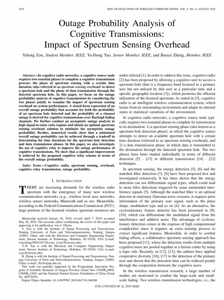
Fig. 1. (a) Coexistence of a primary wireless network and a cognitiveradio network; (b) the allocation of time durations: hole detection versus datatransmission.
which accounts for both the probability of no spectrum holedetected and the probability of a channel outage, for cognitivetransmissions. Finally, in order to improve the system perfor-mance, we propose a cognitive relay transmission scheme andpresent its outage probability analysis over Rayleigh fadingchannels.
The remainder of this paper is organized as follows. Sec-tion II describes the system model of cognitive transmissionthat considers both the spectrum hole detection and datatransmission phases, followed by the outage analysis in Sec-tion III, where the corresponding numerical evaluations arealso provided to show the system performance of cognitivetransmission. In Section IV, we propose a cognitive relaytransmission scheme along with its performance analysis.Numerical results are also presented in this section. Finally,we make some concluding remarks in Section V.
II. SYSTEM MODEL
Consider a cognitive radio network where a cognitive source(CS) is sending data to a cognitive destination (CD) over aspectrum hole unoccupied by a primary user (PU), as shown inFig. 1 (a). Specifically, if CS detects an idle licensed frequencychannel (that is not occupied currently by PU), it will usethis channel for its data transmission (secondary data trans-mission); otherwise, CS will continue detecting the licensedfrequency band to seek an available transmission opportunity.From Fig. 1, one can see that the whole cognitive transmissionprocess is divided into two phases: 1) hole detection of thelicensed band and 2) data transmission from CS to CD. Theallocation of time durations between the two phases is depictedin Fig. 1 (b), where the detection phase and the transmissionphase occupy 𝛼 and 1-𝛼 fractions, respectively, of one timeslot, and 𝛼 is referred to as spectrum sensing overhead thatcan be varied to optimize the system performance. Notice thatsuch a cognitive transmission protocol will be extended to acognitive relay network in Section IV.
In Fig. 1 (a), each transmission link between any twonodes is modeled as a Rayleigh fading process and,moreover, the fading channel is considered as constant
2678 IEEE TRANSACTIONS ON WIRELESS COMMUNICATIONS, VOL. 9, NO. 8, AUGUST 2010
during one time slot. The transmit power of PU and CSare 𝑃𝑝 and 𝑃𝑠, respectively. For notational convenience, let𝐻𝑝(𝑘, 1) and 𝐻𝑝(𝑘, 2) denote whether or not the licensedband is occupied by PU in the first and second phases,respectively, of time slot 𝑘, i.e, 𝐻𝑝(𝑘, 1) = 𝐻𝑝(𝑘, 2) = 𝐻0
represents the band being unoccupied by PU and,otherwise, 𝐻𝑝(𝑘, 1) = 𝐻𝑝(𝑘, 2) = 𝐻1. A Bernoullidistribution with parameter Pa is used to model therandom variable 𝐻𝑝(𝑘, 1), i.e., Pr (𝐻𝑝(𝑘, 1) = 𝐻0) = Pa
and Pr (𝐻𝑝(𝑘, 1) = 𝐻1) = 1 − Pa. Moreover, thetransition between 𝐻𝑝(𝑘, 1) and 𝐻𝑝(𝑘, 2) is modeled asa Markov chain with parameter 1 − exp[−(1− 𝛼)𝜆],i.e., Pr (𝐻𝑝(𝑘, 2) = 𝐻1∣𝐻𝑝(𝑘, 1) = 𝐻0) =Pr (𝐻𝑝(𝑘, 2) = 𝐻0∣𝐻𝑝(𝑘, 1) = 𝐻1) = 1 − exp[−(1− 𝛼)𝜆]and Pr (𝐻𝑝(𝑘, 2) = 𝐻0∣𝐻𝑝(𝑘, 1) = 𝐻0) =Pr (𝐻𝑝(𝑘, 2) = 𝐻1∣𝐻𝑝(𝑘, 1) = 𝐻1) = exp[−(1− 𝛼)𝜆],where 𝜆 is the characteristic parameter. Thus, the signaldetected by CS from PU can be expressed as
𝑦𝑠(𝑘) = ℎ𝑝𝑠(𝑘)√𝑃𝑝𝜃(𝑘, 1) + 𝑛𝑠(𝑘) (1)
where ℎ𝑝𝑠(𝑘) is the fading coefficient of the channel from PUto CS at time slot 𝑘, 𝑛𝑠(𝑘) is AWGN with zero mean and thepower spectral density 𝑁0, and 𝜃(𝑘, 1) is defined as
𝜃(𝑘, 1) =
{0, 𝐻𝑝(𝑘, 1) = 𝐻0
𝑥𝑝(𝑘, 1), 𝐻𝑝(𝑘, 1) = 𝐻1
where 𝑥𝑝(𝑘, 1) is the transmission signal of PU during the firstphase (namely hole detection phase) of time slot 𝑘. Based on(1), CS will make a decision �̂�𝑠(𝑘) on whether the licensedband is occupied by PU. Specifically, �̂�𝑠(𝑘) = 𝐻0 consid-ers that the band is available for secondary transmissions;�̂�𝑠(𝑘) = 𝐻1 considers the band is unavailable. Therefore,the signal received at CD from CS can be written as
𝑦𝑑(𝑘) = ℎ𝑠𝑑(𝑘)√𝑃𝑠𝛽(𝑘) + ℎ𝑝𝑑(𝑘)
√𝑃𝑝𝜃(𝑘, 2) + 𝑛𝑑(𝑘) (2)
where ℎ𝑠𝑑(𝑘) and ℎ𝑝𝑑(𝑘) are the fading coefficients of thechannel from CS to CD and that from PU to CD, respectively.In addition, 𝛽(𝑘) and 𝜃(𝑘, 2) are defined as follows,
𝛽(𝑘) =
{𝑥𝑠(𝑘), �̂�𝑠(𝑘) = 𝐻0
0, �̂�𝑠(𝑘) = 𝐻1
and
𝜃(𝑘, 2) =
{0, 𝐻𝑝(𝑘, 2) = 𝐻0
𝑥𝑝(𝑘, 2), 𝐻𝑝(𝑘, 2) = 𝐻1
where 𝑥𝑠(𝑘) and 𝑥𝑝(𝑘, 2) are the transmission signals of CSat time slot 𝑘 and that of PU at the second phase of time slot𝑘, respectively.
III. OUTAGE ANALYSIS OF COGNITIVE TRANSMISSIONS
IN RAYLEIGH FADING CHANNELS
In this section, we start with the outage analysis of cognitivetransmissions and then conduct the numerical evaluations toshow the impact of spectrum sensing overhead.
A. Outage Probability Analysis
As is known [31], [16], [19], an outage event occurs whenthe channel capacity falls below the data rate 𝑅. Following(2), the outage probability of cognitive transmissions is givenby (3) at the top of the following page, where the coefficient1−𝛼 is due to the fact that only 1−𝛼 fraction of a time slotis utilized for the CS’s data transmission phase. Consideringconditional probabilities, (3) can be expanded as (4) at thetop of the following page, where Λ = [2𝑅/(1−𝛼) − 1]/𝛾𝑠,𝛾𝑠 = 𝑃𝑠/𝑁0 and 𝛾𝑝 = 𝑃𝑝/𝑁0. For notational convenience,let Pa = Pr(𝐻𝑝(𝑘, 1) = 𝐻0) be the probability that there isa hole, Pf = Pr(�̂�𝑠(𝑘) = 𝐻1∣𝐻𝑝(𝑘, 1) = 𝐻0) and Pd =Pr(�̂�𝑠(𝑘) = 𝐻1∣𝐻𝑝(𝑘, 1) = 𝐻1) be the probability of falsealarm and the probability of detection of the primary-user-presence, respectively. Accordingly, (4) can be rewritten as (5)at the top of the following page. Note that there are severalapproaches available for the spectrum hole detection, such asenergy detector, matched filter detector and cyclostationaryfeature detector as shown in [5] - [13]. Throughout this paper,we consider the use of an energy detector for the spectrumsensing performance analysis. Accordingly, considering anenergy detection method and following (1), the output statisticof energy detector at time slot 𝑘 is given by
𝑇 (𝑦) =1
𝑁
𝑁∑𝑛=1
∣𝑦𝑠(𝑘, 𝑛)∣2 (6)
where 𝑁 = 𝛼𝑇𝑓𝑠 is the number of samples, 𝑇 and 𝑓𝑠 are thetime slot length and sample frequency, respectively. From (6),the probability of false alarm and the probability of detection,Pf(𝑘) and Pd(𝑘), of the primary-user-presence at time slot 𝑘are calculated as
Pf(𝑘) = Pr(�̂�𝑠(𝑘) = 𝐻1∣𝐻𝑝(𝑘, 1) = 𝐻0)
= Pr{𝑇 (𝑦) > 𝛿∣𝐻𝑝(𝑘, 1) = 𝐻0}(7)
and
Pd(𝑘) = Pr(�̂�𝑠(𝑘) = 𝐻1∣𝐻𝑝(𝑘, 1) = 𝐻1)
= Pr{𝑇 (𝑦) > 𝛿∣𝐻𝑝(𝑘, 1) = 𝐻1}(8)
where 𝛿 is the energy detection threshold. Using the results ofAppendix A, we obtain
Pout =Pa exp[−(1− 𝛼)𝜆](1 − Pf)[1− exp(− Λ
𝜎2𝑠𝑑
)]
+ Pa[1− exp(−(1− 𝛼)𝜆)](1 − Pf)
× [1− 𝜎2𝑠𝑑
𝜎2𝑝𝑑𝛾𝑝Λ + 𝜎2
𝑠𝑑
exp(− Λ
𝜎2𝑠𝑑
)]
+ (1− Pa)[1− exp(−(1− 𝛼)𝜆)](1 − Pd)
× [1− exp(− Λ
𝜎2𝑠𝑑
)]
+ (1− Pa) exp[−(1− 𝛼)𝜆](1 − Pd)
× [1− 𝜎2𝑠𝑑
𝜎2𝑝𝑑𝛾𝑝Λ + 𝜎2
𝑠𝑑
exp(− Λ
𝜎2𝑠𝑑
)]
+ PaPf + (1− Pa)Pd
(9)
ZOU et al.: OUTAGE PROBABILITY ANALYSIS OF COGNITIVE TRANSMISSIONS: IMPACT OF SPECTRUM SENSING OVERHEAD 2679
Pout = Pr
{(1− 𝛼) log
(1 +
∣ℎ𝑠𝑑(𝑘)∣2 𝑃𝑠 ∣𝛽(𝑘)∣2∣ℎ𝑝𝑑(𝑘)∣2 𝑃𝑝 ∣𝜃(𝑘, 2)∣2 +𝑁0
)< 𝑅
}(3)
Pout =Pr(�̂�𝑠(𝑘) = 𝐻0, 𝐻𝑝(𝑘, 1) = 𝐻0, 𝐻𝑝(𝑘, 2) = 𝐻0) Pr{∣ℎ𝑠𝑑(𝑘)∣2 < Λ}+ Pr(�̂�𝑠(𝑘) = 𝐻0, 𝐻𝑝(𝑘, 1) = 𝐻0, 𝐻𝑝(𝑘, 2) = 𝐻1) Pr{∣ℎ𝑠𝑑(𝑘)∣2 − ∣ℎ𝑝𝑑(𝑘)∣2𝛾𝑝Λ < Λ}+ Pr(�̂�𝑠(𝑘) = 𝐻0, 𝐻𝑝(𝑘, 1) = 𝐻1, 𝐻𝑝(𝑘, 2) = 𝐻0) Pr{∣ℎ𝑠𝑑(𝑘)∣2 < Λ}+ Pr(�̂�𝑠(𝑘) = 𝐻0, 𝐻𝑝(𝑘, 1) = 𝐻1, 𝐻𝑝(𝑘, 2) = 𝐻1) Pr{∣ℎ𝑠𝑑(𝑘)∣2 − ∣ℎ𝑝𝑑(𝑘)∣2𝛾𝑝Λ < Λ}+ Pr(�̂�𝑠(𝑘) = 𝐻1)
(4)
Pout =Pa exp[−(1− 𝛼)𝜆](1 − Pf) Pr{∣ℎ𝑠𝑑(𝑘)∣2 < Λ}+ Pa[1− exp(−(1− 𝛼)𝜆)](1 − Pf) Pr{∣ℎ𝑠𝑑(𝑘)∣2 − ∣ℎ𝑝𝑑(𝑘)∣2𝛾𝑝Λ < Λ}+ (1 − Pa)[1 − exp(−(1 − 𝛼)𝜆)](1 − Pd) Pr{∣ℎ𝑠𝑑(𝑘)∣2 < Λ}+ (1 − Pa) exp[−(1− 𝛼)𝜆](1 − Pd) Pr{∣ℎ𝑠𝑑(𝑘)∣2 − ∣ℎ𝑝𝑑(𝑘)∣2𝛾𝑝Λ < Λ}+ PaPf + (1 − Pa)Pd
(5)
where the false alarm probability Pf is constrained to thedetection probability Pd as given below
Pf =
⎧⎨⎩Pd, Pd = 𝑄(−√
𝑁)
Pd −𝑄(𝑄−1(Pd) +1
𝜎2𝑝𝑠𝜅
) exp(𝜉), otherwise
(10)where 𝜅 = 𝛾𝑝𝑄
−1(Pd) +√𝑁𝛾𝑝, 𝜉 = 𝑄−1(Pd)
𝜎2ps𝜅
+ 12𝜎4
ps𝜅2 , and
the number of samples 𝑁 should satisfy 𝑁 ≥ [𝑄−1(Pd)]2. As
can be observed from (9), the derived closed-from expressionof outage probability accounts for both the probability ofno available channel detected in the spectrum hole detectionphase and the probability of channel outage occurred in thesubsequent data transmission phase, and thus we call it overalloutage probability. Following (9) and letting 𝛾𝑠 → +∞, weare able to obtain an overall outage probability floor
Pout,floor = PaPf + (1− Pa)Pd (11)
which can also be explained as follows. Once CS detects aspectrum hole (no matter it is a correct or a false detection)in the first phase, a channel outage would not occur in thesubsequent data transmission phase due to 𝛾𝑠 → +∞. Inother words, when 𝛾𝑠 → +∞, the outage occurs only whenCS detects the presence of PU (i.e., no hole is detected)no matter whether PU really presents or not. Combining (9)and (10), one can see that the overall outage probability ofthe cognitive transmission is a function of {Pa,Pd,Pf , 𝑅,𝜎2𝑝𝑠, 𝜎
2𝑝𝑑, 𝜎
2𝑠𝑑, 𝛾𝑠, 𝛾𝑝, 𝛼}, where the data rate 𝑅 may often be
set by the system in accordance with the QoS requirement andthe network environment, and the spectrum sensing overhead𝛼 is a parameter that can be adapted to optimize the systemperformance. To obtain a general expression for an optimal 𝛼∗
as a function of the other parameters is very complicated andinfeasible. Here, we consider an asymptotic outage probabilityanalysis to decide the optimal value 𝛼∗. Considering the caseof Pa = 1 and 𝜆 = 0 and letting 𝛾𝑠 → ∞, we can obtain
from (9) using the Taylor approximation as
Pout∼= (1− Pf)
Λ
𝜎2𝑠𝑑
+ Pf (12)
Letting 𝛾𝑝 → ∞, we can similarly apply the Taylor approxi-mation to (10) and obtain
Pf∼= Pd − Pd(1 +
𝑄−1(Pd)
[𝑄−1(Pd) +√𝑁 ]𝜎2
𝑝𝑠
⋅ 1
𝛾𝑝)
= − Pd𝑄−1(Pd)
[𝑄−1(Pd) +√𝛼𝑇𝑓𝑠]𝜎2
𝑝𝑠
⋅ 1
𝛾𝑝
(13)
In obtaining the first equation of (13), we have ignoredthe term 1/(2𝜎4
𝑝𝑠𝜅2), since it is a higher-order infinitesimal
compared to the term 𝑄−1(Pd)/(𝜎2𝑝𝑠𝜅) for 𝛾𝑝 → ∞. Differ-
entiating (12) with respective to the spectrum sensing overhead𝛼 yields
∂Pout
∂𝛼= (1− Pf)
∂Λ
𝜎2𝑠𝑑∂𝛼
+ (1 − Λ
𝜎2𝑠𝑑
)∂Pf
∂𝛼
∼= ∂Λ
𝜎2𝑠𝑑∂𝛼
+∂Pf
∂𝛼
(14)
where the second equation is obtained due to the fact thatPf and Λ are infinitesimal when 𝛾𝑝, 𝛾𝑠 → ∞. Meanwhile,∂Pf/∂𝛼 and ∂Λ/∂𝛼 are given by
∂Pf
∂𝛼=
Pd𝑄−1(Pd)
√𝑇𝑓𝑠
2𝛾𝑝𝜎2𝑝𝑠
√𝛼[𝑄−1(Pd) +
√𝛼𝑇𝑓𝑠]2
(15)
and∂Λ
∂𝛼=
𝑅2𝑅/(1−𝛼) ln 2
(1− 𝑎)2𝛾𝑠(16)
By substituting ∂Pf/∂𝛼 and ∂Λ/∂𝛼 from (15) and (16) into(14), the optimal spectrum sensing overhead should satisfy thefollowing equation
2𝑅/(1−𝛼∗)√𝛼∗[√𝛼∗𝑇𝑓𝑠 +𝑄−1(Pd)]
2𝜉 + (1 − 𝛼∗)2𝜁 = 0(17)
2680 IEEE TRANSACTIONS ON WIRELESS COMMUNICATIONS, VOL. 9, NO. 8, AUGUST 2010
TABLE ILIST OF THE OPTIMAL SPECTRUM SENSING OVERHEAD 𝛼∗ UNDER THE
DIFFERENT PRIMARY AND SECONDARY TRANSMIT SIGNAL-TO-NOISERATIOS (𝛾𝑠, 𝛾𝑝).
wherein 𝜉 and 𝜁 are given by
𝜉 = 𝜎2𝑝𝑠𝛾𝑝𝑅 ln 4; 𝜁 = 𝜎2
𝑠𝑑𝛾𝑠√𝑇𝑓𝑠Pd𝑄
−1(Pd) (18)
An optimal spectrum sensing overhead 𝛼∗ can be easily deter-mined by using (17). In Table 1, we show the optimal sensingoverhead under different values of the primary and secondarytransmit powers (𝛾𝑠, 𝛾𝑝) with Pd = 0.99, 𝜎2
𝑝𝑠 = 𝜎2𝑠𝑑 = 1,
𝑅 = 1 bit/s/Hz, 𝑇 = 25 ms and 𝑓𝑠 = 100 kHz. As shownin the first two columns of Table 1, as the primary transmitpower 𝛾𝑝 increases, the optimal spectrum sensing overhead𝛼∗ decreases, which is due to the fact that less time durationis required for the spectrum hole detection phase with anincreasing primary transmit power. From the last two columnsof Table 1, one can also see that the optimal spectrum sensingoverhead increases when the secondary transmit power 𝛾𝑠increases from 𝛾𝑠 = 30 dB to 𝛾𝑠 = 40 dB. This is becausethat as the secondary transmit power increases, less time isneeded for the data transmission phase, thus resulting in alonger time duration available for the spectrum sensing phase.
B. Numerical Results and Analysis
In this subsection, we focus on the numerical evaluations toshow the impact of spectrum sensing overhead on the overalloutage probability performance. Notice that the primary userwould be interfered by the cognitive user when CS does notdetect the presence of PU given that PU is active. Therefore,the probability of detection of the primary-user-presence Pd
shall be set to a required threshold by the cognitive systemto guarantee PU’s QoS. Throughout this paper, we will usePd = 0.99 for the numerical evaluations.
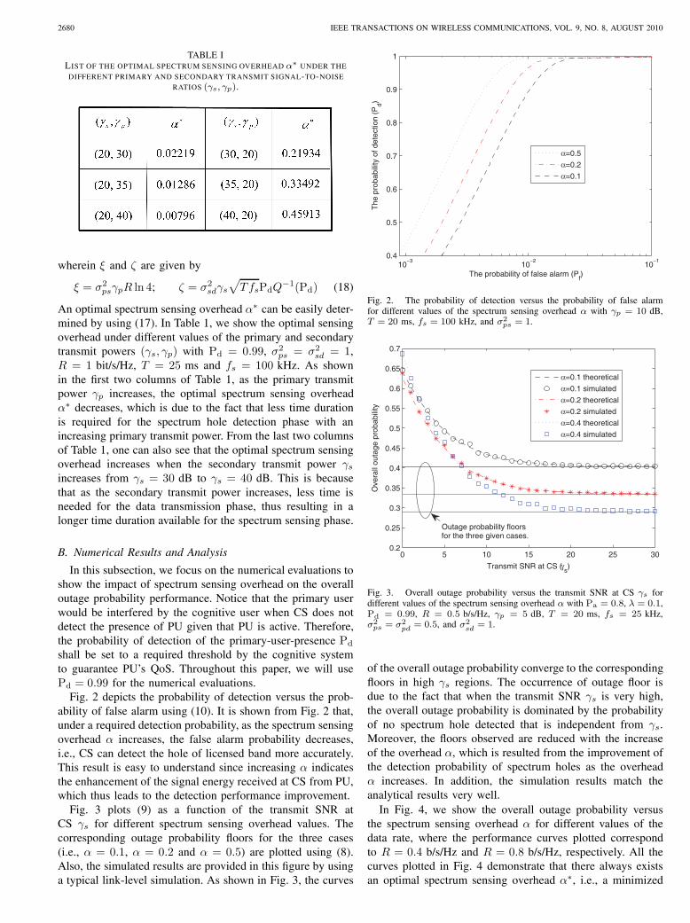
Fig. 2 depicts the probability of detection versus the prob-ability of false alarm using (10). It is shown from Fig. 2 that,under a required detection probability, as the spectrum sensingoverhead 𝛼 increases, the false alarm probability decreases,i.e., CS can detect the hole of licensed band more accurately.This result is easy to understand since increasing 𝛼 indicatesthe enhancement of the signal energy received at CS from PU,which thus leads to the detection performance improvement.
Fig. 3 plots (9) as a function of the transmit SNR atCS 𝛾𝑠 for different spectrum sensing overhead values. Thecorresponding outage probability floors for the three cases(i.e., 𝛼 = 0.1, 𝛼 = 0.2 and 𝛼 = 0.5) are plotted using (8).Also, the simulated results are provided in this figure by usinga typical link-level simulation. As shown in Fig. 3, the curves
10−3
10−2
10−1
0.4
0.5
0.6
0.7
0.8
0.9
1
The probability of false alarm (Pf)
The
pro
babi
lity
of d
etec
tion
(Pd)
α=0.5
α=0.2
α=0.1
Fig. 2. The probability of detection versus the probability of false alarmfor different values of the spectrum sensing overhead 𝛼 with 𝛾𝑝 = 10 dB,𝑇 = 20 ms, 𝑓𝑠 = 100 kHz, and 𝜎2
𝑝𝑠 = 1.
0 5 10 15 20 25 300.2
0.25
0.3
0.35
0.4
0.45
0.5
0.55
0.6
0.65
0.7
Transmit SNR at CS (γs)
Ove
rall
outa
ge p
roba
bilit
y
α=0.1 theoretical
α=0.1 simulated
α=0.2 theoretical
α=0.2 simulated
α=0.4 theoretical
α=0.4 simulated
Outage probability floors for the three given cases.
Fig. 3. Overall outage probability versus the transmit SNR at CS 𝛾𝑠 fordifferent values of the spectrum sensing overhead 𝛼 with Pa = 0.8, 𝜆 = 0.1,Pd = 0.99, 𝑅 = 0.5 b/s/Hz, 𝛾𝑝 = 5 dB, 𝑇 = 20 ms, 𝑓𝑠 = 25 kHz,𝜎2𝑝𝑠 = 𝜎2
𝑝𝑑 = 0.5, and 𝜎2𝑠𝑑 = 1.
of the overall outage probability converge to the correspondingfloors in high 𝛾𝑠 regions. The occurrence of outage floor isdue to the fact that when the transmit SNR 𝛾𝑠 is very high,the overall outage probability is dominated by the probabilityof no spectrum hole detected that is independent from 𝛾𝑠.Moreover, the floors observed are reduced with the increaseof the overhead 𝛼, which is resulted from the improvement ofthe detection probability of spectrum holes as the overhead𝛼 increases. In addition, the simulation results match theanalytical results very well.
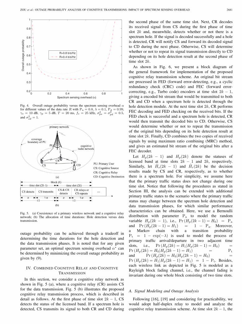
In Fig. 4, we show the overall outage probability versusthe spectrum sensing overhead 𝛼 for different values of thedata rate, where the performance curves plotted correspondto 𝑅 = 0.4 b/s/Hz and 𝑅 = 0.8 b/s/Hz, respectively. All thecurves plotted in Fig. 4 demonstrate that there always existsan optimal spectrum sensing overhead 𝛼∗, i.e., a minimized
ZOU et al.: OUTAGE PROBABILITY ANALYSIS OF COGNITIVE TRANSMISSIONS: IMPACT OF SPECTRUM SENSING OVERHEAD 2681
0 0.2 0.4 0.6 0.8 10.2
0.3
0.4
0.5
0.6
0.7
0.8
0.9
1
Spectrum sensing overhead (α)
Ove
rall
outa
ge p
roba
bilit
y
R=0.8 b/s/HzR=0.4 b/s/Hz
Fig. 4. Overall outage probability versus the spectrum sensing overhead 𝛼for different values of the data rate 𝑅 with Pa = 0.8, 𝜆 = 0.1, Pd = 0.99,𝛾𝑠 = 10 dB, 𝛾𝑝 = 5 dB, 𝑇 = 20 ms, 𝑓𝑠 = 25 kHz, 𝜎2
𝑝𝑠 = 𝜎2𝑝𝑑 = 0.5,
and 𝜎2𝑠𝑑 = 1.
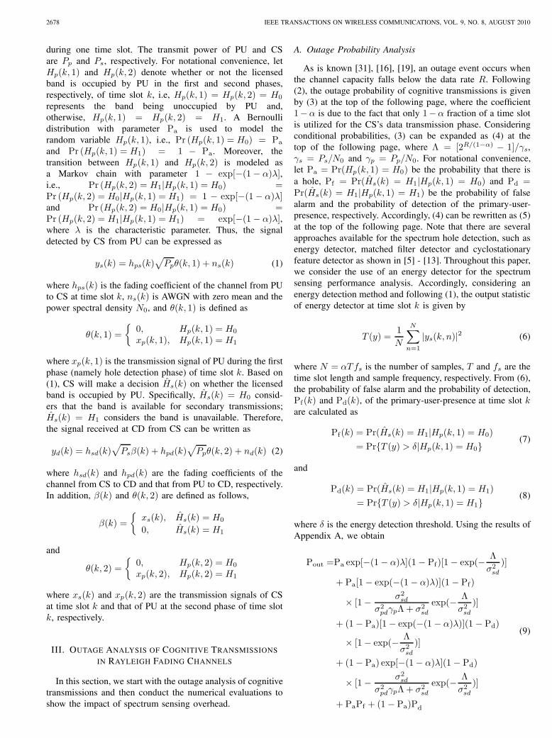
Fig. 5. (a) Coexistence of a primary wireless network and a cognitive relaynetwork; (b) The allocation of time durations: Hole detection versus datatransmission.
outage probability can be achieved through a tradeoff indetermining the time durations for the hole detection andthe data transmission phases. It is noted that for any givenparameter set, an optimal spectrum sensing overhead 𝛼∗ canbe determined by minimizing the overall outage probability asgiven by (9).
IV. COMBINED COGNITIVE RELAY AND COGNITIVE
TRANSMISSION
In this section, we consider a cognitive relay network asshown in Fig. 5 (a), where a cognitive relay (CR) assists CSfor the data transmission. Fig. 5 (b) illustrates the proposedcognitive relay transmission process, which is described indetail as follows. At the first phase of time slot 2𝑘 − 1, CSdetects the status of the licensed band. If a spectrum hole isdetected, CS transmits its signal to both CR and CD during
the second phase of the same time slot. Next, CR decodesits received signal from CS during the first phase of timeslot 2𝑘 and, meanwhile, detects whether or not there is aspectrum hole. If the signal is decoded successfully and a holeis detected, CR will notify CS and forward its decoded signalto CD during the next phase. Otherwise, CS will determinewhether or not to repeat its signal transmission directly to CDdepending on its hole detection result at the second phase oftime slot 2𝑘.
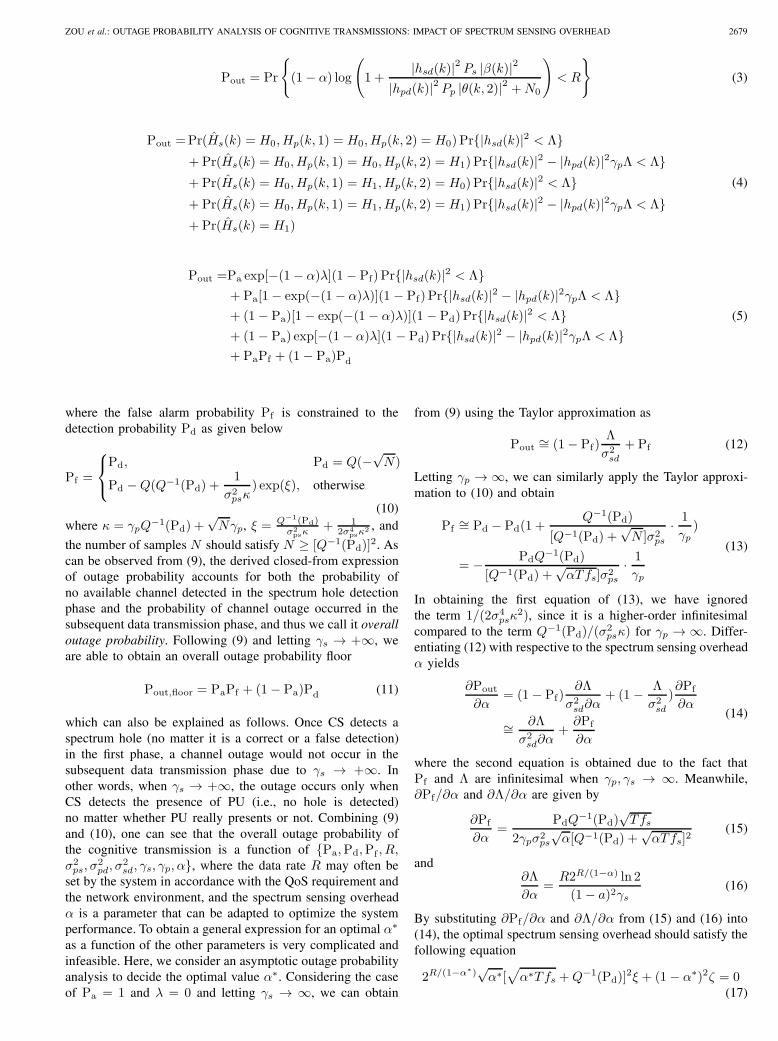
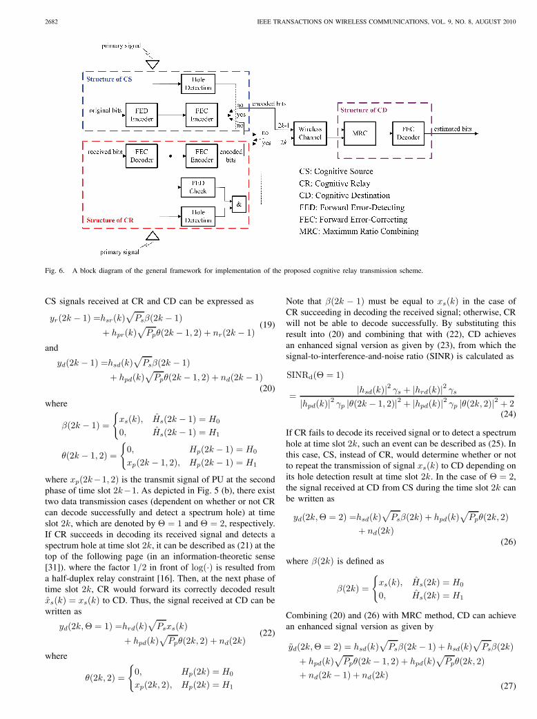
As shown in Fig. 6, we present a block diagram ofthe general framework for implementation of the proposedcognitive relay transmission scheme. An original bit streamare processed in FED (forward error-detecting, e.g., a cyclicredundancy check (CRC) code) and FEC (forward error-correcting, e.g., Turbo code) encoders at time slot 2𝑘 − 1,giving a encoded bit stream that would be transmitted to bothCR and CD when a spectrum hole is detected through thehole detection module. At the next time slot 2𝑘, CR performsFEC decoding and FED checking on the received bits. If theFED check is successful and a spectrum hole is detected, CRwould then transmit the decoded bits to CD. Otherwise, CSwould determine whether or not to repeat the transmissionof the original bits depending on its hole detection result attime slot 2𝑘. Finally, CD combines the two copies of receivedsignals by using maximum ratio combining (MRC) method,and gives an estimated bit stream of the original bits after aFEC decoder.
Let 𝐻𝑝(2𝑘 − 1) and 𝐻𝑝(2𝑘) denote the statuses oflicensed band at time slots 2𝑘 − 1 and 2𝑘, respectively.Similarly, let �̂�𝑠(2𝑘 − 1) and �̂�𝑟(2𝑘) be the decisionresults made by CS and CR, respectively, as to whetherthere is a spectrum hole. For simplicity, we assume herethat the primary traffic status does not change during onetime slot. Notice that following the procedures as stated inSection III, the analysis can be extended with additionalprimary traffic states to the scenario where the primary trafficstatus may change between the spectrum hole detection anddata transmission phases, for which similar performancecharacteristics can be obtained. Here, we use a Bernoullidistribution with parameter Pa to model the randomvariable 𝐻𝑝(2𝑘 − 1), i.e., Pr (𝐻𝑝(2𝑘 − 1) = 𝐻0) = Pa
and Pr (𝐻𝑝(2𝑘 − 1) = 𝐻1) = 1 − Pa. Moreover,a Markov chain with a transition probabilityPt = 1 − exp(−𝜆) is used to model the process ofprimary traffic arrival/departure in two adjacent timeslots, i.e., Pr (𝐻𝑝(2𝑘) = 𝐻1∣𝐻𝑝(2𝑘 − 1) = 𝐻0) =Pr (𝐻𝑝(2𝑘) = 𝐻0∣𝐻𝑝(2𝑘 − 1) = 𝐻1) = Pt
and Pr (𝐻𝑝(2𝑘) = 𝐻0∣𝐻𝑝(2𝑘 − 1) = 𝐻0) =Pr (𝐻𝑝(2𝑘) = 𝐻1∣𝐻𝑝(2𝑘 − 1) = 𝐻1) = 1 − Pt. Besides,each wireless link as depicted in Fig. 5 is modeled as aRayleigh block fading channel, i.e., the channel fading isinvariant during one whole block consisting of two time slots.
A. Signal Modeling and Outage Analysis
Following [16], [19] and considering for practicability, wewould adopt half-duplex relay to model and analyze thecognitive relay transmission scheme. At time slot 2𝑘− 1, the
2682 IEEE TRANSACTIONS ON WIRELESS COMMUNICATIONS, VOL. 9, NO. 8, AUGUST 2010
Fig. 6. A block diagram of the general framework for implementation of the proposed cognitive relay transmission scheme.
CS signals received at CR and CD can be expressed as
𝑦𝑟(2𝑘 − 1) =ℎ𝑠𝑟(𝑘)√𝑃𝑠𝛽(2𝑘 − 1)
+ ℎ𝑝𝑟(𝑘)√𝑃𝑝𝜃(2𝑘 − 1, 2) + 𝑛𝑟(2𝑘 − 1)
(19)
and
𝑦𝑑(2𝑘 − 1) =ℎ𝑠𝑑(𝑘)√𝑃𝑠𝛽(2𝑘 − 1)
+ ℎ𝑝𝑑(𝑘)√𝑃𝑝𝜃(2𝑘 − 1, 2) + 𝑛𝑑(2𝑘 − 1)
(20)
where
𝛽(2𝑘 − 1) =
{𝑥𝑠(𝑘), �̂�𝑠(2𝑘 − 1) = 𝐻0
0, �̂�𝑠(2𝑘 − 1) = 𝐻1
𝜃(2𝑘 − 1, 2) =
{0, 𝐻𝑝(2𝑘 − 1) = 𝐻0
𝑥𝑝(2𝑘 − 1, 2), 𝐻𝑝(2𝑘 − 1) = 𝐻1
where 𝑥𝑝(2𝑘−1, 2) is the transmit signal of PU at the secondphase of time slot 2𝑘−1. As depicted in Fig. 5 (b), there existtwo data transmission cases (dependent on whether or not CRcan decode successfully and detect a spectrum hole) at timeslot 2𝑘, which are denoted by Θ = 1 and Θ = 2, respectively.If CR succeeds in decoding its received signal and detects aspectrum hole at time slot 2𝑘, it can be described as (21) at thetop of the following page (in an information-theoretic sense[31]). where the factor 1/2 in front of log(⋅) is resulted froma half-duplex relay constraint [16]. Then, at the next phase oftime slot 2𝑘, CR would forward its correctly decoded result�̂�𝑠(𝑘) = 𝑥𝑠(𝑘) to CD. Thus, the signal received at CD can bewritten as
𝑦𝑑(2𝑘,Θ = 1) =ℎ𝑟𝑑(𝑘)√𝑃𝑠𝑥𝑠(𝑘)
+ ℎ𝑝𝑑(𝑘)√𝑃𝑝𝜃(2𝑘, 2) + 𝑛𝑑(2𝑘)
(22)
where
𝜃(2𝑘, 2) =
{0, 𝐻𝑝(2𝑘) = 𝐻0
𝑥𝑝(2𝑘, 2), 𝐻𝑝(2𝑘) = 𝐻1
Note that 𝛽(2𝑘 − 1) must be equal to 𝑥𝑠(𝑘) in the case ofCR succeeding in decoding the received signal; otherwise, CRwill not be able to decode successfully. By substituting thisresult into (20) and combining that with (22), CD achievesan enhanced signal version as given by (23), from which thesignal-to-interference-and-noise ratio (SINR) is calculated as
SINRd(Θ = 1)
=∣ℎ𝑠𝑑(𝑘)∣2 𝛾𝑠 + ∣ℎ𝑟𝑑(𝑘)∣2 𝛾𝑠
∣ℎ𝑝𝑑(𝑘)∣2 𝛾𝑝 ∣𝜃(2𝑘 − 1, 2)∣2 + ∣ℎ𝑝𝑑(𝑘)∣2 𝛾𝑝 ∣𝜃(2𝑘, 2)∣2 + 2(24)
If CR fails to decode its received signal or to detect a spectrumhole at time slot 2𝑘, such an event can be described as (25). Inthis case, CS, instead of CR, would determine whether or notto repeat the transmission of signal 𝑥𝑠(𝑘) to CD depending onits hole detection result at time slot 2𝑘. In the case of Θ = 2,the signal received at CD from CS during the time slot 2𝑘 canbe written as
𝑦𝑑(2𝑘,Θ = 2) =ℎ𝑠𝑑(𝑘)√𝑃𝑠𝛽(2𝑘) + ℎ𝑝𝑑(𝑘)
√𝑃𝑝𝜃(2𝑘, 2)
+ 𝑛𝑑(2𝑘)(26)
where 𝛽(2𝑘) is defined as
𝛽(2𝑘) =
{𝑥𝑠(𝑘), �̂�𝑠(2𝑘) = 𝐻0
0, �̂�𝑠(2𝑘) = 𝐻1
Combining (20) and (26) with MRC method, CD can achievean enhanced signal version as given by
𝑦𝑑(2𝑘,Θ = 2) = ℎ𝑠𝑑(𝑘)√𝑃𝑠𝛽(2𝑘 − 1) + ℎ𝑠𝑑(𝑘)
√𝑃𝑠𝛽(2𝑘)
+ ℎ𝑝𝑑(𝑘)√𝑃𝑝𝜃(2𝑘 − 1, 2) + ℎ𝑝𝑑(𝑘)
√𝑃𝑝𝜃(2𝑘, 2)
+ 𝑛𝑑(2𝑘 − 1) + 𝑛𝑑(2𝑘)(27)
ZOU et al.: OUTAGE PROBABILITY ANALYSIS OF COGNITIVE TRANSMISSIONS: IMPACT OF SPECTRUM SENSING OVERHEAD 2683
Θ = 1 :(1− 𝛼)
2log
(1 +
∣ℎ𝑠𝑟(𝑘)∣2 𝛾𝑠 ∣𝛽(2𝑘 − 1)∣2∣ℎ𝑝𝑟(𝑘)∣2 𝛾𝑝 ∣𝜃(2𝑘 − 1, 2)∣2 + 1
)> 𝑅 and �̂�𝑟(2𝑘) = 𝐻0 (21)
𝑦𝑑(2𝑘,Θ = 1) = ℎ𝑠𝑑(𝑘)√𝑃𝑠𝑥𝑠(𝑘)+ℎ𝑟𝑑(𝑘)
√𝑃𝑠𝑥𝑠(𝑘)+ℎ𝑝𝑑(𝑘)
√𝑃𝑝𝜃(2𝑘−1, 2)+ℎ𝑝𝑑(𝑘)
√𝑃𝑝𝜃(2𝑘, 2)+𝑛𝑑(2𝑘−1)+𝑛𝑑(2𝑘)
(23)
Θ = 2 :(1− 𝛼)
2log
(1 +
∣ℎ𝑠𝑟(𝑘)∣2 𝛾𝑠 ∣𝛽(2𝑘 − 1)∣2∣ℎ𝑝𝑟(𝑘)∣2 𝛾𝑝 ∣𝜃(2𝑘 − 1, 2)∣2 + 1
)< 𝑅 or �̂�𝑟(2𝑘) = 𝐻1 (25)
from which the corresponding SINR can be calculated as
SINRd(Θ = 2)
=∣ℎ𝑠𝑑(𝑘)∣2 𝛾𝑠 ∣𝛽(2𝑘 − 1)∣2 + ∣ℎ𝑠𝑑(𝑘)∣2 𝛾𝑠 ∣𝛽(2𝑘)∣2
∣ℎ𝑝𝑑(𝑘)∣2 𝛾𝑝 ∣𝜃(2𝑘 − 1, 2)∣2 + ∣ℎ𝑝𝑑(𝑘)∣2 𝛾𝑝 ∣𝜃(2𝑘, 2)∣2 + 2(28)
Now, we have formulated the signal models for the cognitiverelay transmission, based on which a detailed analysis of theoverall outage probability is presented in the following, andalso a performance comparison with the non-relay transmis-sion is conducted to illustrate the advantage of the proposedcognitive relay scheme. According to the coding theorem [31],an outage event is deemed to occur when the channel capacityfalls below the data rate 𝑅. Thus, we can calculate the overalloutage probability of the cognitive relay transmission as
Pout,relay = Pr
{1− 𝛼
2log (1 + SINRd) < 𝑅
}
= Pr
{1− 𝛼
2log (1 + SINRd(Θ = 1)) < 𝑅,Θ = 1
}
+ Pr
{1− 𝛼
2log (1 + SINRd(Θ = 2)) < 𝑅,Θ = 2
}
= Pr {SINRd(Θ = 1) < 𝛾𝑠Δ,Θ = 1}+ Pr {SINRd(Θ = 2) < 𝛾𝑠Δ,Θ = 2}
(29)
where Δ = [22𝑅/(1−𝛼) − 1]/𝛾𝑠. Using the results fromAppendix B, we can obtain
Pout,relay = B2(a)+B2(b)+B2(c)+B2(d)+B12(a)−B12(b)(30)
Closed-form expressions of B2(a), B2(b), B2(c), B2(d),B12(a) and B12(b) are presented in Appendix B as givenby (B.5), (B.7), (B.8), (B.9), (B.13) and (B.14), respectively.As can be seen from (30), obtaining a general expression foran optimal spectrum sensing overhead 𝛼 as a function of theother parameters is very difficult. However, an optimal 𝛼 valuecan be determined through numerical computation.
B. Numerical Results and Analysis
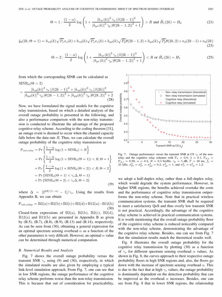
Fig. 7 shows the overall outage probability versus thetransmit SNR 𝛾𝑠 using (9) and (30), respectively, in whichthe simulated results are also given by employing a typicallink-level simulation approach. From Fig. 7, one can see thatin low SNR regions, the outage performance of the cognitiverelay scheme performs worse than the non-relay transmission.This is because that out of consideration for practicability,
0 5 10 15 20 25 300.2
0.3
0.4
0.5
0.6
0.7
0.8
0.9
1
Transmit SNR at CS (γs)
Ove
rall
outa
ge p
roba
bilit
y
Non−relay transmission (theoretical)Non−relay transmission (simulated)Cognitive relay (theoretical)Cognitive relay (simulated)
Fig. 7. Outage performance versus the transmit SNR at CS 𝛾𝑠 of the non-relay and the cognitive relay schemes with Pa = 0.8, 𝜆 = 0.1, Pd,s =Pd,r = 0.99, 𝛼 = 0.2, 𝑅 = 0.5 b/s/Hz, 𝛾𝑝 = 5 dB, 𝑇 = 20 ms, 𝑓𝑠 =25 kHz, 𝜎2
𝑝𝑠 = 𝜎2𝑝𝑟 = 𝜎2
𝑝𝑑 = 0.2, 𝜎2𝑠𝑑 = 1, and 𝜎2
𝑠𝑟 = 𝜎2𝑟𝑑 = 1.2.
we adopt a half-duplex relay, rather than a full-duplex relay,which would degrade the system performance. However, inhigher SNR regions, the benefits achieved overtake the costsand the performance of cognitive relay transmission outper-forms the non-relay scheme. Note that in practical wirelesscommunication systems, the transmit SNR shall be requiredto meet a satisfactory QoS and thus overly low transmit SNRis not practical. Accordingly, the advantage of the cognitiverelay scheme is achieved in practical communication systems.It is worth mentioning that the overall outage probability floorof the cognitive relay scheme is reduced noticeably comparedwith the non-relay scheme, demonstrating the advantage ofthe cognitive relay scheme. Besides, one can see from Fig. 7that the simulation results match the theoretical results well.
Fig. 8 illustrates the overall outage probability for thecognitive relay transmission by plotting (30) as a functionof 𝛾𝑠 for different spectrum sensing overhead 𝛼 values. Asshown in Fig. 8, the curves approach to their respective outageprobability floors in high SNR regions and, also, the floors godown with the increase of spectrum sensing overhead 𝛼. Thisis due to the fact that at high 𝛾𝑠 values, the outage probabilityis dominantly dependent on the detection probability that canbe improved as the overhead 𝛼 increases. Besides, one cansee from Fig. 8 that in lower SNR regions, the relationship
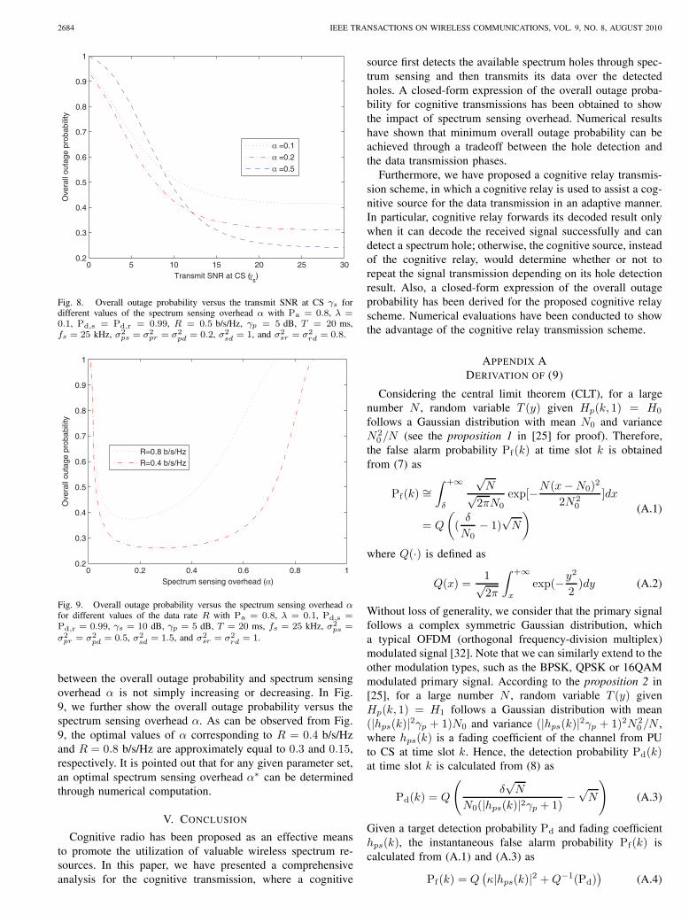
2684 IEEE TRANSACTIONS ON WIRELESS COMMUNICATIONS, VOL. 9, NO. 8, AUGUST 2010
0 5 10 15 20 25 300.2
0.3
0.4
0.5
0.6
0.7
0.8
0.9
1
Transmit SNR at CS (γs)
Ove
rall
outa
ge p
roba
bilit
y
α =0.1
α =0.2
α =0.5
Fig. 8. Overall outage probability versus the transmit SNR at CS 𝛾𝑠 fordifferent values of the spectrum sensing overhead 𝛼 with Pa = 0.8, 𝜆 =0.1, Pd,s = Pd,r = 0.99, 𝑅 = 0.5 b/s/Hz, 𝛾𝑝 = 5 dB, 𝑇 = 20 ms,𝑓𝑠 = 25 kHz, 𝜎2
𝑝𝑠 = 𝜎2𝑝𝑟 = 𝜎2
𝑝𝑑 = 0.2, 𝜎2𝑠𝑑 = 1, and 𝜎2
𝑠𝑟 = 𝜎2𝑟𝑑 = 0.8.
0 0.2 0.4 0.6 0.8 10.2
0.3
0.4
0.5
0.6
0.7
0.8
0.9
1
Spectrum sensing overhead (α)
Ove
rall
outa
ge p
roba
bilit
y
R=0.8 b/s/HzR=0.4 b/s/Hz
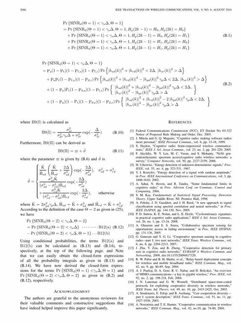
Fig. 9. Overall outage probability versus the spectrum sensing overhead 𝛼for different values of the data rate 𝑅 with Pa = 0.8, 𝜆 = 0.1, Pd,s =Pd,r = 0.99, 𝛾𝑠 = 10 dB, 𝛾𝑝 = 5 dB, 𝑇 = 20 ms, 𝑓𝑠 = 25 kHz, 𝜎2
𝑝𝑠 =𝜎2𝑝𝑟 = 𝜎2
𝑝𝑑 = 0.5, 𝜎2𝑠𝑑 = 1.5, and 𝜎2
𝑠𝑟 = 𝜎2𝑟𝑑 = 1.
between the overall outage probability and spectrum sensingoverhead 𝛼 is not simply increasing or decreasing. In Fig.9, we further show the overall outage probability versus thespectrum sensing overhead 𝛼. As can be observed from Fig.9, the optimal values of 𝛼 corresponding to 𝑅 = 0.4 b/s/Hzand 𝑅 = 0.8 b/s/Hz are approximately equal to 0.3 and 0.15,respectively. It is pointed out that for any given parameter set,an optimal spectrum sensing overhead 𝛼∗ can be determinedthrough numerical computation.
V. CONCLUSION
Cognitive radio has been proposed as an effective meansto promote the utilization of valuable wireless spectrum re-sources. In this paper, we have presented a comprehensiveanalysis for the cognitive transmission, where a cognitive
source first detects the available spectrum holes through spec-trum sensing and then transmits its data over the detectedholes. A closed-form expression of the overall outage proba-bility for cognitive transmissions has been obtained to showthe impact of spectrum sensing overhead. Numerical resultshave shown that minimum overall outage probability can beachieved through a tradeoff between the hole detection andthe data transmission phases.
Furthermore, we have proposed a cognitive relay transmis-sion scheme, in which a cognitive relay is used to assist a cog-nitive source for the data transmission in an adaptive manner.In particular, cognitive relay forwards its decoded result onlywhen it can decode the received signal successfully and candetect a spectrum hole; otherwise, the cognitive source, insteadof the cognitive relay, would determine whether or not torepeat the signal transmission depending on its hole detectionresult. Also, a closed-form expression of the overall outageprobability has been derived for the proposed cognitive relayscheme. Numerical evaluations have been conducted to showthe advantage of the cognitive relay transmission scheme.
APPENDIX ADERIVATION OF (9)
Considering the central limit theorem (CLT), for a largenumber 𝑁 , random variable 𝑇 (𝑦) given 𝐻𝑝(𝑘, 1) = 𝐻0
follows a Gaussian distribution with mean 𝑁0 and variance𝑁2
0 /𝑁 (see the proposition 1 in [25] for proof). Therefore,the false alarm probability Pf(𝑘) at time slot 𝑘 is obtainedfrom (7) as
Pf(𝑘) ∼=∫ +∞
𝛿
√𝑁√
2𝜋𝑁0
exp[−𝑁(𝑥−𝑁0)2
2𝑁20
]𝑑𝑥
= 𝑄
((𝛿
𝑁0− 1)
√𝑁
) (A.1)
where 𝑄(⋅) is defined as
𝑄(𝑥) =1√2𝜋
∫ +∞
𝑥
exp(−𝑦2
2)𝑑𝑦 (A.2)
Without loss of generality, we consider that the primary signalfollows a complex symmetric Gaussian distribution, whicha typical OFDM (orthogonal frequency-division multiplex)modulated signal [32]. Note that we can similarly extend to theother modulation types, such as the BPSK, QPSK or 16QAMmodulated primary signal. According to the proposition 2 in[25], for a large number 𝑁 , random variable 𝑇 (𝑦) given𝐻𝑝(𝑘, 1) = 𝐻1 follows a Gaussian distribution with mean(∣ℎ𝑝𝑠(𝑘)∣2𝛾𝑝 + 1)𝑁0 and variance (∣ℎ𝑝𝑠(𝑘)∣2𝛾𝑝 + 1)2𝑁2
0 /𝑁 ,where ℎ𝑝𝑠(𝑘) is a fading coefficient of the channel from PUto CS at time slot 𝑘. Hence, the detection probability Pd(𝑘)at time slot 𝑘 is calculated from (8) as
Pd(𝑘) = 𝑄
(𝛿√𝑁
𝑁0(∣ℎ𝑝𝑠(𝑘)∣2𝛾𝑝 + 1)−√𝑁
)(A.3)
Given a target detection probability Pd and fading coefficientℎ𝑝𝑠(𝑘), the instantaneous false alarm probability Pf(𝑘) iscalculated from (A.1) and (A.3) as
Pf(𝑘) = 𝑄(𝜅∣ℎ𝑝𝑠(𝑘)∣2 +𝑄−1(Pd)
)(A.4)

ZOU et al.: OUTAGE PROBABILITY ANALYSIS OF COGNITIVE TRANSMISSIONS: IMPACT OF SPECTRUM SENSING OVERHEAD 2685
where 𝜅 = 𝛾𝑝𝑄−1(Pd) +
√𝑁𝛾𝑝 and 𝑄−1(⋅) is an inverse
𝑄(⋅) function. Notice that RV 𝑋 = ∣ℎ𝑝𝑠(𝑘)∣2 follows anexponential distribution with parameter 1/𝜎2
𝑝𝑠. Therefore, theaverage false alarm probability Pf can be calculated as
Pf =
∫ ∞
0
𝑄(𝜅𝑥+𝑄−1(Pd)
) 1
𝜎2𝑝𝑠
exp(− 𝑥
𝜎2𝑝𝑠
)𝑑𝑥
=
∫∫Ξ
1
𝜎2𝑝𝑠
exp(− 𝑥
𝜎2𝑝𝑠
)1√2𝜋
exp(−𝑦2
2)𝑑𝑥𝑑𝑦
(A.5)
where Ξ ={(𝑥, 𝑦)∣0 < 𝑥 < ∞, 𝜅𝑥+𝑄−1(Pd) < 𝑦 < ∞}.
Integrating (A.5) first with respect to 𝑥, then with respect to𝑦, we obtain
Pf =
⎧⎨⎩
Pd + [1−𝑄(𝑄−1(Pd) +1
𝜎2𝑝𝑠𝜅
)] exp(𝜉), 𝑄(−√𝑁) < Pd ≤ 1
Pd, Pd = 𝑄(−√𝑁)
Pd −𝑄(𝑄−1(Pd) +1
𝜎2𝑝𝑠𝜅
) exp(𝜉), 0 ≤ Pd < 𝑄(−√𝑁)
(A.6)
where 𝜉 = 𝑄−1(Pd)𝜎2ps𝜅
+ 12𝜎4
ps𝜅2 . From detection theory, for any
reasonable detector, Pf is always smaller than or equal to Pd,or else it is worse than tossing a coin. Therefore, the numberof samples 𝑁 should satisfy
𝑁 ≥ [𝑄−1(Pd)]2 (A.7)
which is due to the fact that from central limit theorem, thenumber of samples should be sufficiently large so that the out-put statistic 𝑇 (𝑦) of the energy detector can be approximatedto a Gaussian distribution. Combining (A.6) and (A.7) yields
Pf =
⎧⎨⎩Pd, Pd = 𝑄(−√
𝑁)
Pd −𝑄(𝑄−1(Pd) +1
𝜎2𝑝𝑠𝜅
) exp(𝜉), otherwise
(A.8)Note that RVs ∣ℎ𝑠𝑑(𝑘)∣2 and ∣ℎ𝑝𝑑(𝑘)∣2 follow the exponentialdistribution with parameters 1/𝜎2
𝑠𝑑 and 1/𝜎2𝑝𝑑, respectively,
and are independent of each other. Thus, the probabilityintegrals given in (5) can be calculated as
Pr{∣ℎ𝑠𝑑(𝑘)∣2 < Λ
}= 1− exp(− Λ
𝜎2𝑠𝑑
) (A.9)
and
Pr{∣ℎ𝑠𝑑(𝑘)∣2 − ∣ℎ𝑝𝑑(𝑘)∣2 𝛾𝑝Λ < Λ
}=
∫∫Ω
1
𝜎2𝑠𝑑
exp(− 𝑥
𝜎2𝑠𝑑
)1
𝜎2𝑝𝑑
exp(− 𝑦
𝜎2𝑝𝑑
)𝑑𝑥𝑑𝑦(A.10)
where Ω = {(𝑥, 𝑦)∣𝑥− 𝑦𝛾𝑝Λ < Λ}. Eq. (A.10) can be derivedas
Pr{∣ℎ𝑠𝑑(𝑘)∣2 − ∣ℎ𝑝𝑑(𝑘)∣2 𝛾𝑝Λ < Λ
}= 1− 𝜎2
𝑠𝑑
𝜎2𝑝𝑑𝛾𝑝Λ + 𝜎2
𝑠𝑑
exp(− Λ
𝜎2𝑠𝑑
)(A.11)
Substituting (A.9) and (A.11) into (5) yields (9).
APPENDIX BCALCULATION OF (17)
The term Pr {SINRd(Θ = 1) < 𝛾𝑠Δ,Θ = 1} given in (29)can be rewritten as (B.1) at the top of the following page.By using conditional probabilities, (B.1) can be calculated as
(B.2), where Pf,s and Pd,s are, respectively, the probability offalse alarm and the probability of detection of the primary-user-presence by CS and, moreover, Pf,r and Pd,r are thecorresponding probabilities of primary user detection by CR.Similar to (A.9), it is easy to show
Pf,s =
⎧⎨⎩Pd,s, Pd,s = 𝑄(−√
𝑁)
Pd,s −𝑄(𝑄−1(Pd,s) +1
𝜎2𝑝𝑠𝜅𝑠
) exp(𝜉𝑠), otherwise
(B.3)and
Pf,r =
⎧⎨⎩Pd,r, Pd,r = 𝑄(−√
𝑁)
Pd,r −𝑄(𝑄−1(Pd,r) +1
𝜎2𝑝𝑠𝜅𝑟
) exp(𝜉𝑟), otherwise
(B.4)where 𝜅𝑠 = 𝛾𝑝𝑄
−1(Pd,s) +√𝑁𝛾𝑝, 𝜉𝑠 =
𝑄−1(Pd,s)𝜎2𝑝𝑠𝜅𝑠
+
12𝜎4
𝑝𝑠𝜅2𝑠, 𝜅𝑟 = 𝛾𝑝𝑄
−1(Pd,r) +√𝑁𝛾𝑝 𝜉𝑟 =
𝑄−1(Pd,r)𝜎2𝑝𝑟𝜅𝑟
+1
2𝜎4𝑝𝑟𝜅
2𝑟, and the number of samples satisfies 𝑁 ≥
max{[Q−1(Pd,s)]2, [Q−1(Pd,r)]
2}. Clearly, the first term,B2(a), as given in (B.2) is given by
B2(a) = Pa(1−Pt)(1 − Pf,s)(1−Pf,r)exp(− Δ
𝜎2𝑠𝑟
)𝜛 (B.5)
where parameter 𝜛 is given by
𝜛 =
⎧⎨⎩
1− (1 +2Δ
𝜎2𝑠𝑑
) exp(− 2Δ
𝜎2𝑠𝑑
), 𝜎2𝑠𝑑 = 𝜎2
𝑟𝑑
1− 𝜎2𝑠𝑑
𝜎2𝑠𝑑 − 𝜎2
𝑟𝑑
exp(− 2Δ
𝜎2𝑠𝑑
)
− 𝜎2𝑟𝑑
𝜎2𝑟𝑑 − 𝜎2
𝑠𝑑
exp(− 2Δ
𝜎2𝑟𝑑
), otherwise
(B.6)
Also, the second term, B2(b), in (B.2) is calculated as
B2(b) =Pt(1− Pd,r)
(1− Pt)(1 − Pf,r)B2(a)
+ PaPt(1− Pf,s)(1 − Pd,r)exp(− Δ
𝜎2𝑠𝑟
)𝜗
(B.7)
where B2(a) is given in (B.5) and the parameter 𝜗 is givenby
𝜗 =
⎧⎨⎩
K
H𝑠𝑑
(K
H𝑠𝑑+
2Δ
𝜎2𝑠𝑑
)exp(− 2Δ
𝜎2𝑠𝑑
), 𝜎2𝑠𝑑 = 𝜎2
𝑟𝑑
𝜎2𝑠𝑑K
(𝜎2𝑠𝑑 − 𝜎2
𝑟𝑑)H𝑠𝑑exp(− 2Δ
𝜎2𝑠𝑑
)
+𝜎2𝑟𝑑K
(𝜎2𝑟𝑑 − 𝜎2
𝑠𝑑)H𝑟𝑑exp(− 2Δ
𝜎2𝑟𝑑
), otherwise
where Δ = [22𝑅/(1−𝛼)−1]/𝛾𝑠, K = 𝜎2𝑝𝑑𝛾𝑝Δ, H𝑠𝑑 = K+𝜎2
𝑠𝑑
and H𝑟𝑑 = K+ 𝜎2𝑟𝑑. Similarly, the third term, B2(c), in (B.2)
is calculated as
B2(c) =(1− Pa)(1− Pd,s)(1− Pf,r)𝜎
2𝑠𝑟
Pa(1− Pf,s)(1− Pd,r)(𝜎2𝑠𝑟 + 𝜎2
𝑝𝑟𝛾𝑝Δ)× B2(b)
(B.8)where B2(b) is given in (B.7). Besides, the fourth term, B2(d),as given in (B.2) is calculated as
B2(d) = (1− Pa)(1− Pt)(1− Pd,s)(1− Pd,r)
× Pr{∣ℎ𝑠𝑟(𝑘)∣2 − ∣ℎ𝑝𝑟(𝑘)∣2 𝛾𝑝Δ > Δ
} ⋅ ⋅ ⋅ ⋅ ⋅ ⋅ ⋅ ⋅ ⋅ ⋅ ⋅ ⋅ ⋅ ⋅ ⋅B9(I)× Pr
{∣ℎ𝑠𝑑(𝑘)∣2 + ∣ℎ𝑟𝑑(𝑘)∣2 − 2 ∣ℎ𝑝𝑑(𝑘)∣2 𝛾𝑝Δ < 2Δ} ⋅ ⋅ ⋅B9(II)
(B.9)
2686 IEEE TRANSACTIONS ON WIRELESS COMMUNICATIONS, VOL. 9, NO. 8, AUGUST 2010
Pr {SINRd(Θ = 1) < 𝛾𝑠Δ,Θ = 1}= Pr {SINRd(Θ = 1) < 𝛾𝑠Δ,Θ = 1, 𝐻𝑝(2𝑘 − 1) = 𝐻0, 𝐻𝑝(2𝑘) = 𝐻0}+ Pr {SINRd(Θ = 1) < 𝛾𝑠Δ,Θ = 1, 𝐻𝑝(2𝑘 − 1) = 𝐻0, 𝐻𝑝(2𝑘) = 𝐻1}+ Pr {SINRd(Θ = 1) < 𝛾𝑠Δ,Θ = 1, 𝐻𝑝(2𝑘 − 1) = 𝐻1, 𝐻𝑝(2𝑘) = 𝐻0}+ Pr {SINRd(Θ = 1) < 𝛾𝑠Δ,Θ = 1, 𝐻𝑝(2𝑘 − 1) = 𝐻1, 𝐻𝑝(2𝑘) = 𝐻1}
(B.1)
Pr {SINRd(Θ = 1) < 𝛾𝑠Δ,Θ = 1}= Pa(1− Pt)(1− Pf,s)(1 − Pf,r) Pr
{∣ℎ𝑠𝑑(𝑘)∣2 + ∣ℎ𝑟𝑑(𝑘)∣2 < 2Δ, ∣ℎ𝑠𝑟(𝑘)∣2 > Δ
}+ PaPt(1 − Pf,s)(1− Pd,r) Pr
{∣ℎ𝑠𝑑(𝑘)∣2 + ∣ℎ𝑟𝑑(𝑘)∣2 − ∣ℎ𝑝𝑑(𝑘)∣2 𝛾𝑝Δ < 2Δ, ∣ℎ𝑠𝑟(𝑘)∣2 > Δ
}+ (1− Pa)Pt(1− Pd,s)(1− Pf,r) Pr
{ ∣ℎ𝑠𝑑(𝑘)∣2 + ∣ℎ𝑟𝑑(𝑘)∣2 − ∣ℎ𝑝𝑑(𝑘)∣2 𝛾𝑝Δ < 2Δ,
∣ℎ𝑠𝑟(𝑘)∣2 − ∣ℎ𝑝𝑟(𝑘)∣2 𝛾𝑝Δ > Δ
}
+ (1− Pa)(1 − Pt)(1 − Pd,s)(1 − Pd,r) Pr
{ ∣ℎ𝑠𝑑(𝑘)∣2 + ∣ℎ𝑟𝑑(𝑘)∣2 − 2 ∣ℎ𝑝𝑑(𝑘)∣2 𝛾𝑝Δ < 2Δ,
∣ℎ𝑠𝑟(𝑘)∣2 − ∣ℎ𝑝𝑟(𝑘)∣2 𝛾𝑝Δ > Δ
}(B.2)
where B9(I) is calculated as
B9(I) =𝜎2𝑠𝑟
𝜎2𝑝𝑟𝛾𝑝Δ+ 𝜎2
𝑠𝑟
exp(− Δ
𝜎2𝑠𝑟
) (B.10)
Furthermore, B9(II) can be derived as
B9(II) = 𝜛 + 𝜗 (B.11)
where the parameter 𝜛 is given by (B.6) and 𝜗 is
𝜗 =
⎧⎨⎩
K̃
H̃𝑠𝑑
(K̃
H̃𝑠𝑑
+2Δ
𝜎2𝑠𝑑
)exp(− 2Δ
𝜎2𝑠𝑑
), 𝜎2𝑠𝑑 = 𝜎2
𝑟𝑑
𝜎2𝑠𝑑K̃
(𝜎2𝑠𝑑 − 𝜎2
𝑟𝑑)H̃𝑠𝑑
exp(− 2Δ
𝜎2𝑠𝑑
)
+𝜎2𝑟𝑑K̃
(𝜎2𝑟𝑑 − 𝜎2
𝑠𝑑)H̃𝑟𝑑
exp(− 2Δ
𝜎2𝑟𝑑
), otherwise
where K̃ = 2𝜎2𝑝𝑑𝛾𝑝Δ, H̃𝑠𝑑 = K̃ + 𝜎2
𝑠𝑑 and H̃𝑟𝑑 = K̃ + 𝜎2𝑟𝑑.
According to the definition of the case Θ = 2 as given in (25),we have
Pr {SINRd(Θ = 2) < 𝛾𝑠Δ,Θ = 2}= Pr {SINRd(Θ = 2) < 𝛾𝑠Δ} ⋅ ⋅ ⋅ ⋅ ⋅ ⋅ ⋅ ⋅ ⋅B12(a)− Pr {SINRd(Θ = 2) < 𝛾𝑠Δ,Θ = 1} ⋅ ⋅ ⋅B12(b)
(B.12)
Using conditional probabilities, the terms B12(a) andB12(b) can be calculated as (B.13) and (B.14), re-spectively, at the top of the following page. and Notethat we can easily obtain the closed-form expressionsof all the probability integrals as given in (B.13) and(B.14). We have now derived the closed-form expres-sions for the terms Pr {SINRd(Θ = 1) <𝛾𝑠Δ,Θ = 1} andPr {SINRd(Θ = 2) <𝛾𝑠Δ,Θ = 2} as given in (B.2) and(B.12), respectively.
ACKNOWLEDGMENT
The authors are grateful to the anonymous reviewers fortheir valuable comments and constructive suggestions thathave indeed helped improve this paper significantly.
REFERENCES
[1] Federal Communications Commission (FCC), ET Docket No 03-322Notice of Proposed Rule Making and Order, Dec. 2003.
[2] J. Mitola and G. Q. Maguire, “Cognitive radio: making software radiosmore personal,” IEEE Personal Commun., vol. 6, pp. 13-18, 1999.
[3] S. Haykin, “Cognitive radio: brain-empowered wireless communica-tions,” IEEE J. Sel. Areas Commun., vol. 23, no. 2, pp. 201-220, 2005.
[4] F. Akyildiz, W. Y. Lee, M. C. Vuran, and S. Mohanty, “NeXt gen-eration/dynamic spectrum access/cognitive radio wireless networks: asurvey,” Computer Networks, vol. 50, pp. 2127-2159, 2006.
[5] H. Urkowitz, “Energy detection of unknown deterministic signals,” Proc.IEEE, vol. 55, no. 4, pp. 523-531, 1967.
[6] V. I. Kostylev, “Energy detection of a signal with random amptitude,”in Proc. IEEE International Conference on Communications, vol. 3, pp.1606-1610, 2002.
[7] A. Sahai, N. Hoven, and R. Tandra, “Some fundamental limits incognitive radio,” in Proc. Allerton Conf. on Commun., Control andComputing, 2004.
[8] S. M. Kay, Fundamentals of Statistical Signal Processing: DetectionTheory. Upper Saddle River, NJ: Prentice Hall, 1998.
[9] A. Fehske, J. D. Gaeddert, and J. H. Reed, “A new approach to signalclassification using spectral correlation and neural networks,” in Proc.IEEE DySPAN, pp. 144-150, Nov. 2005.
[10] P. D. Sutton, K. E. Nolan, and L. E. Doyle, “Cyclostationary signaturesin practical cognitive radio applications,” IEEE J. Sel. Areas Commun.,vol. 26, no. 1, pp. 13-24, 2008.
[11] A. Ghasemi and E. S. Sousa, “Collaborative spectrum sensing foropportunistic access in fading environment,” in Proc. IEEE DYSPAN,pp. 131-136, 2005.
[12] G. Ganesan and Y. G. Li, “Cooperative spectrum sensing in cognitiveradio—part I: two user networks,” IEEE Trans. Wireless Commun., vol.6, no. 6, pp. 2204-2213, 2007.
[13] J. Zhu, Y. Zou, and B. Zheng, “Cooperative detection for primaryuser in cognitive radio networks,” EURASIP J. Wireless Commun. andNetworking, 2009, doi:10.1155/2009/617320.
[14] R. W. Pabst and B. H. Shultz, et al., “Relay-based deployment conceptsfor wireless and mobile broadband radio,” IEEE Commun. Mag., vol.42, no. 9, pp. 80-89, Sep. 2004.
[15] A. J. Paulraj, D. A. Gore, R. U. Nabar, and H. Bolcskei, “An overviewof MIMO communications—a key to gigabit wireless,” Proc. IEEE, vol.92, no. 2, pp. 198-218, Feb. 2004.
[16] J. N. Laneman and G. W. Wornell, “Distributed space-time-codedprotocols for exploiting cooperative diversity in wireless networks,”IEEE Trans. Inf. Theory, vol. 49, no. 10, pp. 2415-2425, Oct. 2003.
[17] A. Sendonaris, E. Erkip, and B. Aazhang, “User cooperation diversity—part I: system description,” IEEE Trans. Commun., vol. 51, no. 11, pp.1927-1938, 2003.
[18] A. Nosratinia and T. E. Hunter, “Cooperative communication in wirelessnetworks,” IEEE Commun. Mag., vol. 42, no.10, pp. 74-80, 2004.
ZOU et al.: OUTAGE PROBABILITY ANALYSIS OF COGNITIVE TRANSMISSIONS: IMPACT OF SPECTRUM SENSING OVERHEAD 2687
B12(a) =Pa(1− Pt)(1 − Pf,s)2 Pr
{∣ℎ𝑠𝑑(𝑘)∣2 < Δ
}+ (1 − Pa)(1 − Pt)(1 − Pd,s)
2 Pr{∣ℎ𝑠𝑑(𝑘)∣2 − ∣ℎ𝑝𝑑(𝑘)∣2 𝛾𝑝Δ < Δ
}+ Pt(1− Pf,s)(1 − Pd,s) Pr
{2 ∣ℎ𝑠𝑑(𝑘)∣2 − ∣ℎ𝑝𝑑(𝑘)∣2 𝛾𝑝Δ < 2Δ
}+ 2Pa(1− Pt)(1 − Pf,s)Pf,sPr
{∣ℎ𝑠𝑑(𝑘)∣2 < 2Δ
}+ 2(1− Pa)(1− Pt)(1 − Pd,s)Pd,sPr
{∣ℎ𝑠𝑑(𝑘)∣2 − 2 ∣ℎ𝑝𝑑(𝑘)∣2 𝛾𝑝Δ < 2Δ
}+ Pt(Pd,s + Pf,s−2Pf,sPd,s) Pr
{∣ℎ𝑠𝑑(𝑘)∣2 − ∣ℎ𝑝𝑑(𝑘)∣2 𝛾𝑝Δ < 2Δ
}+ Pa(1− Pt)P
2f,s + PtPd,sPf,s + (1− Pa)(1− Pt)P
2d,s
(B.13)
B12(b) =Pa(1 − Pt)(1 − Pf,s)2(1− Pf,r) Pr
{∣ℎ𝑠𝑑(𝑘)∣2 < Δ
}Pr{∣ℎ𝑠𝑟(𝑘)∣2 > Δ
}+ PaPt(1 − Pf,s)(1− Pd,s)(1− Pd,r) Pr
{2 ∣ℎ𝑠𝑑(𝑘)∣2 − ∣ℎ𝑝𝑑(𝑘)∣2 𝛾𝑝Δ < 2Δ
}× Pr
{∣ℎ𝑠𝑟(𝑘)∣2 > Δ
}+ (1− Pa)Pt(1− Pf,s)(1 − Pd,s)(1 − Pf,r) Pr
{2 ∣ℎ𝑠𝑑(𝑘)∣2 − ∣ℎ𝑝𝑑(𝑘)∣2 𝛾𝑝Δ < 2Δ
}× Pr
{∣ℎ𝑠𝑟(𝑘)∣2 − ∣ℎ𝑝𝑟(𝑘)∣2 𝛾𝑝Δ > Δ
}+ (1− Pa)(1 − Pt)(1 − Pd,s)
2(1− Pd,r) Pr{∣ℎ𝑠𝑑(𝑘)∣2 − ∣ℎ𝑝𝑑(𝑘)∣2 𝛾𝑝Δ < Δ
}× Pr
{∣ℎ𝑠𝑟(𝑘)∣2 − ∣ℎ𝑝𝑟(𝑘)∣2 𝛾𝑝Δ>Δ
}+ Pa(1− Pt)(1− Pf,s)Pf,s(1 − Pf,r) Pr
{∣ℎ𝑠𝑑(𝑘)∣2 < 2Δ
}Pr{∣ℎ𝑠𝑟(𝑘)∣2 > Δ
}+ PaPt(1 − Pf,s)Pd,s(1− Pd,r) Pr
{∣ℎ𝑠𝑑(𝑘)∣2 − ∣ℎ𝑝𝑑(𝑘)∣2 𝛾𝑝Δ < 2Δ
}× Pr
{∣ℎ𝑠𝑟(𝑘)∣2 > Δ
}+ (1− Pa)Pt(1− Pd,s)Pf,s(1− Pf,r) Pr
{∣ℎ𝑠𝑑(𝑘)∣2 − ∣ℎ𝑝𝑑(𝑘)∣2 𝛾𝑝Δ < 2Δ
}× Pr
{∣ℎ𝑠𝑟(𝑘)∣2 − ∣ℎ𝑝𝑟(𝑘)∣2 𝛾𝑝Δ > Δ
}+ (1− Pa)(1 − Pt)(1 − Pd,s)Pd,s(1− Pd,r) Pr
{∣ℎ𝑠𝑑(𝑘)∣2 − 2 ∣ℎ𝑝𝑑(𝑘)∣2 𝛾𝑝Δ < 2Δ
}× Pr
{∣ℎ𝑠𝑟(𝑘)∣2 − ∣ℎ𝑝𝑟(𝑘)∣2 𝛾𝑝Δ>Δ
}
(B.14)
[19] T. E. Hunter, S. Sanayei, and A. Nosratinia. “Outage analysis of codedcooperation,” IEEE Trans. Inf. Theory, vol. 52, no. 2, pp. 375-391, 2006.
[20] A. Bletsas, A. Khisti, et al., “A simple cooperative diversity methodbased on network path selection,” IEEE J. Sel. Areas Commun., vol. 24,no. 3, pp. 659-672, 2006.
[21] Y. Zou, B. Zheng, and J. Zhu, “Outage analysis of opportunistic cooper-ation over Rayleigh fading channels,” IEEE Trans. Wireless Commun.,vol. 8, no. 6, pp. 3077-3385, June 2009.
[22] Y. Zou, B. Zheng, and W. P. Zhu, “An opportunistic cooperation andits BER analysis,” IEEE Trans. Wireless Commun., vol. 8, no. 9, pp.4492-4497, Sep. 2009.
[23] Y. Zou, J. Zhu, B. Zheng, and Y.-D. Yao, “An adaptive cooperationdiversity scheme with best-relay selection in cognitive radio networks,”accepted to appear in IEEE Trans. Signal Process., 2010.
[24] A. Ghasemi and E. S. Sousa, “Optimization of spectrum sensing foropportunistic spectrum access in cognitive radio networks,” in Proc.Consumer Communications and Networking Conf. (CCNC 2007), Jan.2007, pp. 1022-1026.
[25] Y.-C. Liang, Y. Zeng, E. Peh, and A. T. Hoang, “Sensing-throughputtradeoff for cognitive radio networks,” IEEE Trans. Wireless Commun.,vol. 7, no. 4, pp. 1326-1337, Apr. 2008.
[26] Y. Pei, A. T. Hoang, and Y.-C. Liang, “Sensing-throughput tradeoff incognitive radio networks: how frequently should spectrum sensing be
carried out?” in Proc. IEEE Int. Symp. Personal, Indoor and MobileRadio Commun. (PIMRC 2007), Sep. 2007, pp. 1-5.
[27] W.-Y. Lee and I. F. Akyildiz, “Optimal spectrum sensing framework forcognitive radio networks,” IEEE Trans. Wireless Commun., vol. 7, no.10, pp. 3845-3857, Oct. 2008.
[28] C.-H. Huang, Y.-C. Lai, and K.-C. Chen, “Network capacity of cognitiveradio relay network,” Physical Commun., vol. 1, no. 2, June 2008.
[29] J. Jia, J. Zhang, and Q. Zhang, “Cooperative relay for cognitive radionetworks,” in Proc. IEEE INFOCOM 2009, pp. 2304-2312.
[30] H. V. Poor, An Introduction to Signal Detection and Estimation.Springer-Verlag, 1994.
[31] C. E. Shannon, “A mathmatical theroy of communication,” Bell SystemTechn. J., vol. 27, pp. 379-423, 1948.
[32] S. Masoud, G.-A. Mohammad, and H. K. Babak, “On the peak-to-average power of OFDM signals based on oversampling,” IEEE Trans.Commun., vol. 51, no. 1, pp. 72-78, Jan. 2003.

2688 IEEE TRANSACTIONS ON WIRELESS COMMUNICATIONS, VOL. 9, NO. 8, AUGUST 2010
Yulong Zou received his B.Eng. degree (with thehighest honor) in Information Engineering fromNanjing University of Posts and Telecommunica-tions (NUPT), Nanjing China, in 2006. He is cur-rently working toward his Ph.D. degrees, respec-tively, at the Institute of Signal Processing andTransmission of NUPT, Nanjing China, and theElectrical and Computer Engineering Departmentof Stevens Institute of Technology (SIT), NJ USA.His research interests span the broad area of scal-able wireless communication and networking, with
emphasis on cooperative relay technology. Recently, he focuses on theinvestigation of cooperative relay techniques in cognitive radio networks.
Yu-Dong Yao (S’88-M’88-SM’94) has been withStevens Institute of Technology, Hoboken, New Jer-sey, since 2000 and is currently a professor anddepartment director of electrical and computer en-gineering. He is also a director of Stevens’ Wire-less Information Systems Engineering Laboratory(WISELAB). Previously, from 1989 and 1990, hewas at Carleton University, Ottawa, Canada, as aResearch Associate working on mobile radio com-munications. From 1990 to 1994, he was with SparAerospace Ltd., Montreal, Canada, where he was
involved in research on satellite communications. From 1994 to 2000, he waswith Qualcomm Inc., San Diego, CA, where he participated in research anddevelopment in wireless code-division multiple-access (CDMA) systems.
He holds one Chinese patent and twelve U.S. patents. His researchinterests include wireless communications and networks, spread spectrumand CDMA, antenna arrays and beamforming, cognitive and software definedradio (CSDR), and digital signal processing for wireless systems. Dr. Yao wasan Associate Editor of IEEE Communications Letters and IEEE Transactionson Vehicular Technology, and an Editor for IEEE Transactions on WirelessCommunications. He received the B.Eng. and M.Eng. degrees from NanjingUniversity of Posts and Telecommunications, Nanjing, China, in 1982 and1985, respectively, and the Ph.D. degree from Southeast University, Nanjing,China, in 1988, all in electrical engineering.
Baoyu Zheng received B.S. and M.S. degreesfrom the Department of Circuit and Signal System,NUPT, in 1969 and 1981, respectively. Since then,he has been engaged in teaching and researching atSignal and Information Processing. He is a full pro-fessor and doctoral advisor at NUPT. His researchinterests span the broad area of the intelligent signalprocessing, wireless network and signal processingfor modern communication, and the quantum signalprocessing.
Recommended