1.Waterfall Model
Waterfall approach was first Process Model to be introduced and followed widely in
Software Engineering to ensure success of the project. In "The Waterfall" approach,
the whole process of software development is divided into separate process phases.
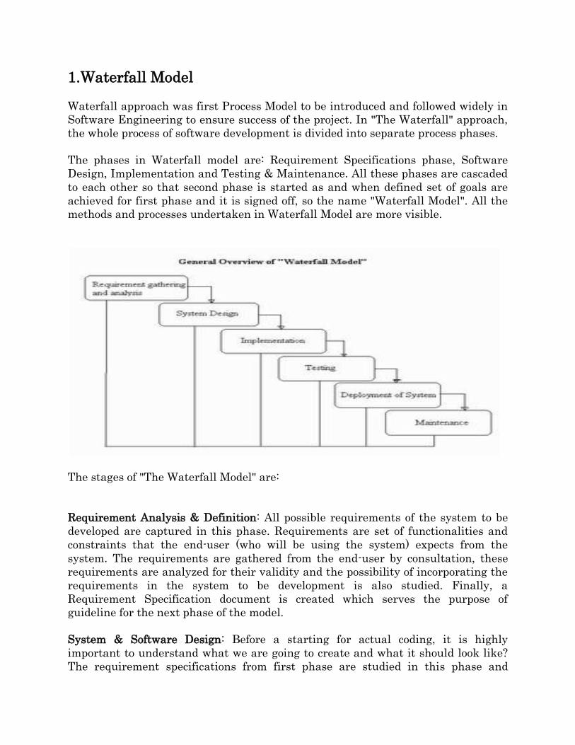
The phases in Waterfall model are: Requirement Specifications phase, Software
Design, Implementation and Testing & Maintenance. All these phases are cascaded
to each other so that second phase is started as and when defined set of goals are
achieved for first phase and it is signed off, so the name "Waterfall Model". All the
methods and processes undertaken in Waterfall Model are more visible.
The stages of "The Waterfall Model" are:
Requirement Analysis & Definition: All possible requirements of the system to be
developed are captured in this phase. Requirements are set of functionalities and
constraints that the end-user (who will be using the system) expects from the
system. The requirements are gathered from the end-user by consultation, these
requirements are analyzed for their validity and the possibility of incorporating the
requirements in the system to be development is also studied. Finally, a
Requirement Specification document is created which serves the purpose of
guideline for the next phase of the model.
System & Software Design: Before a starting for actual coding, it is highly
important to understand what we are going to create and what it should look like?
The requirement specifications from first phase are studied in this phase and
system design is prepared. System Design helps in specifying hardware and system
requirements and also helps in defining overall system architecture. The system
design specifications serve as input for the next phase of the model.
Implementation & Unit Testing: On receiving system design documents, the work is
divided in modules/units and actual coding is started. The system is first developed
in small programs called units, which are integrated in the next phase. Each unit is
developed and tested for its functionality; this is referred to as Unit Testing. Unit
testing mainly verifies if the modules/units meet their specifications.
Integration & System Testing: As specified above, the system is first divided in
units which are developed and tested for their functionalities. These units are
integrated into a complete system during Integration phase and tested to check if
all modules/units coordinate between each other and the system as a whole behaves
as per the specifications. After successfully testing the software, it is delivered to
the customer.
Operations & Maintenance: This phase of "The Waterfall Model" is virtually never
ending phase (Very long). Generally, problems with the system developed (which
are not found during the development life cycle) come up after its practical use
starts, so the issues related to the system are solved after deployment of the system.
Not all the problems come in picture directly but they arise time to time and needs
to be solved; hence this process is referred as Maintenance.
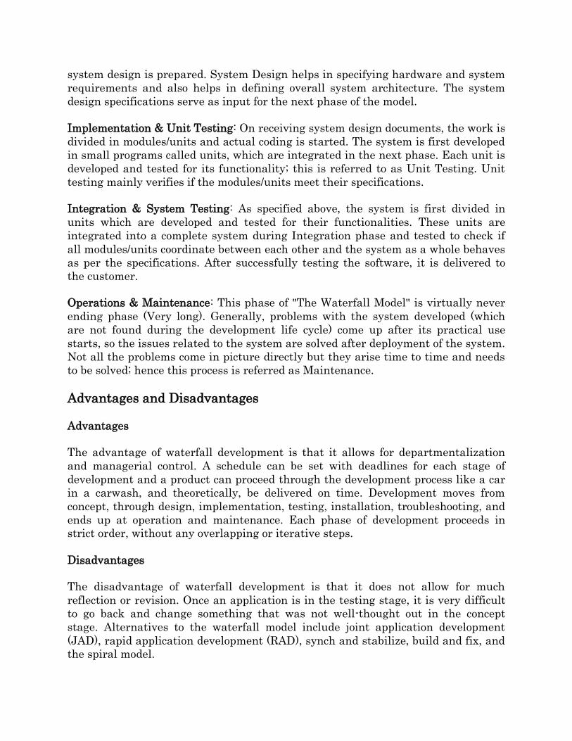
Advantages and Disadvantages
Advantages
The advantage of waterfall development is that it allows for departmentalization
and managerial control. A schedule can be set with deadlines for each stage of
development and a product can proceed through the development process like a car
in a carwash, and theoretically, be delivered on time. Development moves from
concept, through design, implementation, testing, installation, troubleshooting, and
ends up at operation and maintenance. Each phase of development proceeds in
strict order, without any overlapping or iterative steps.
Disadvantages
The disadvantage of waterfall development is that it does not allow for much
reflection or revision. Once an application is in the testing stage, it is very difficult
to go back and change something that was not well-thought out in the concept
stage. Alternatives to the waterfall model include joint application development
(JAD), rapid application development (RAD), synch and stabilize, build and fix, and
the spiral model.
2.Prototyping Model
The Prototyping Model is a systems development method (SDM) in which a
prototype (an early approximation of a final system or product) is built, tested, and
then reworked as necessary until an acceptable prototype is finally achieved from
which the complete system or product can now be developed. This model works best
in scenarios where not all of the project requirements are known in detail ahead of
time. It is an iterative, trial-and-error process that takes place between the
developers and the users.
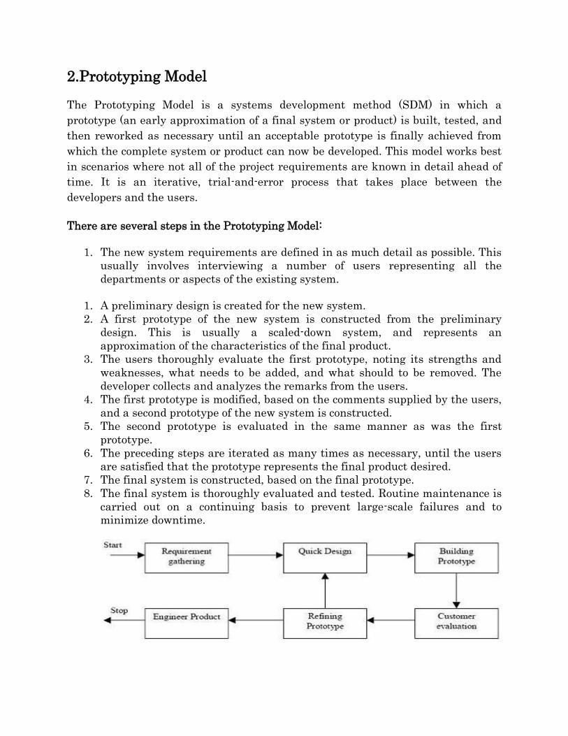
There are several steps in the Prototyping Model:
1. The new system requirements are defined in as much detail as possible. This
usually involves interviewing a number of users representing all the
departments or aspects of the existing system.
1. A preliminary design is created for the new system.
2. A first prototype of the new system is constructed from the preliminary
design. This is usually a scaled-down system, and represents an
approximation of the characteristics of the final product.
3. The users thoroughly evaluate the first prototype, noting its strengths and
weaknesses, what needs to be added, and what should to be removed. The
developer collects and analyzes the remarks from the users.
4. The first prototype is modified, based on the comments supplied by the users,
and a second prototype of the new system is constructed.
5. The second prototype is evaluated in the same manner as was the first
prototype.
6. The preceding steps are iterated as many times as necessary, until the users
are satisfied that the prototype represents the final product desired.
7. The final system is constructed, based on the final prototype.
8. The final system is thoroughly evaluated and tested. Routine maintenance is
carried out on a continuing basis to prevent large-scale failures and to
minimize downtime.
Advantages of Prototyping
1.Users are actively involved in the development
2. It provides a better system to users, as users have natural tendency to change
their mind in specifying requirements and this method of developing systems
supports this user tendency.
3. Since in this methodology a working model of the system is provided, the users
get a better understanding of the system being developed.
4. Errors can be detected much earlier as the system is mode side by side.
5. Quicker user feedback is available leading to better solutions.
Disadvantages
1. Leads to implementing and then repairing way of building systems.
2. Practically, this methodology may increase the complexity of the system as scope
of the system may expand beyond original plans.
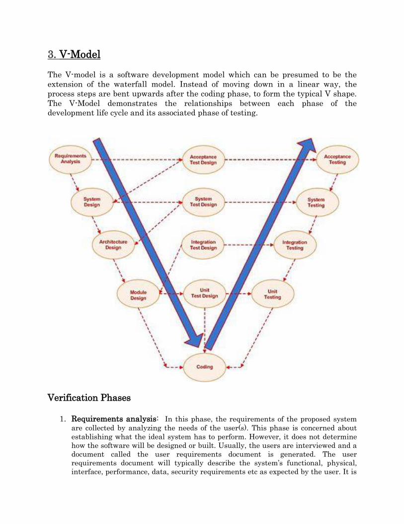
3. V-Model
The V-model is a software development model which can be presumed to be the
extension of the waterfall model. Instead of moving down in a linear way, the
process steps are bent upwards after the coding phase, to form the typical V shape.
The V-Model demonstrates the relationships between each phase of the
development life cycle and its associated phase of testing.
Verification Phases
1. Requirements analysis: In this phase, the requirements of the proposed system
are collected by analyzing the needs of the user(s). This phase is concerned about
establishing what the ideal system has to perform. However, it does not determine
how the software will be designed or built. Usually, the users are interviewed and a
document called the user requirements document is generated. The user
requirements document will typically describe the system’s functional, physical,
interface, performance, data, security requirements etc as expected by the user. It is
one which the business analysts use to communicate their understanding of the
system back to the users. The users carefully review this document as this document
would serve as the guideline for the system designers in the system design phase.
The user acceptance tests are designed in this phase.
2. System Design: System engineers analyze and understand the business of
the proposed system by studying the user requirements document. They
figure out possibilities and techniques by which the user requirements can be
implemented. If any of the requirements are not feasible, the user is informed
of the issue. A resolution is found and the user requirement document is
edited accordingly.
The software specification document which serves as a blueprint for the
development phase is generated. This document contains the general system
organization, menu structures, data structures etc. It may also hold example
business scenarios, sample windows, reports for the better understanding.
Other technical documentation like entity diagrams, data dictionary will also
be produced in this phase. The documents for system testing is prepared in
this phase.
3. Architecture Design: This phase can also be called as high-level design. The
baseline in selecting the architecture is that it should realize all which
typically consists of the list of modules, brief functionality of each module,
their interface relationships, dependencies, database tables, architecture
diagrams, technology details etc. The integration testing design is carried out
in this phase.
4. Module Design: This phase can also be called as low-level design. The
designed system is broken up in to smaller units or modules and each of them
is explained so that the programmer can start coding directly. The low level
design document or program specifications will contain a detailed functional
logic of the module, in pseudocode - database tables, with all elements,
including their type and size - all interface details with complete API
references- all dependency issues- error message listings- complete input and
outputs for a module. The unit test design is developed in this stage.
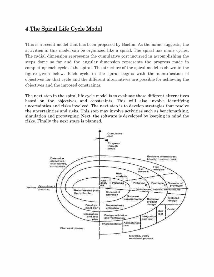
4.The Spiral Life Cycle Model
This is a recent model that has been proposed by Boehm. As the name suggests, the
activities in this model can be organized like a spiral. The spiral has many cycles.
The radial dimension represents the cumulative cost incurred in accomplishing the
steps dome so far and the angular dimension represents the progress made in
completing each cycle of the spiral. The structure of the spiral model is shown in the
figure given below. Each cycle in the spiral begins with the identification of
objectives for that cycle and the different alternatives are possible for achieving the
objectives and the imposed constraints.
The next step in the spiral life cycle model is to evaluate these different alternatives
based on the objectives and constraints. This will also involve identifying
uncertainties and risks involved. The next step is to develop strategies that resolve
the uncertainties and risks. This step may involve activities such as benchmarking,
simulation and prototyping. Next, the software is developed by keeping in mind the
risks. Finally the next stage is planned.
The next step is determined by remaining risks. For example, its performance or
user-interface risks are considered more important than the program development
risks. The next step may be evolutionary development that involves developing a
more detailed prototype for resolving the risks. On the other hand, if the program
development risks dominate and previous prototypes have resolved all the user-
interface and performance risks; the next step will follow the basic waterfall
approach.
The risk driven nature of the spiral model allows it to accommodate any mixture of
specification-oriented, prototype-oriented, simulation-oriented or some other
approach. An important feature of the model is that each cycle of the spiral is
completed by a review, which covers all the products developed during that cycle,
including plans for the next cycle. The spiral model works for developed as well as
enhancement projects.
Spiral Model Description
The development spiral consists of four quadrants as shown in the figure above
Quadrant 1: Determine objectives, alternatives, and constraints.
Quadrant 2: Evaluate alternatives, identify, resolve risks.
Quadrant 3: Develop, verify, next-level product.
Quadrant 4: Plan next phases.
Although the spiral, as depicted, is oriented toward software development, the
concept is equally applicable to systems, hardware, and training, for example. To
better understand the scope of each spiral development quadrant, let’s briefly
address each one.
Quadrant 1: Determine Objectives, Alternatives, and Constraints
Activities performed in this quadrant include:
1. Establish an understanding of the system or product objectives—
namely performance, functionality, and ability to accommodate change.
2. Investigate implementation alternatives—namely design, reuse,
procure, and procure/ modify
3. Investigate constraints imposed on the alternatives—namely
technology, cost, schedule, support, and risk. Once the system or product’s
objectives, alternatives, and constraints are understood, Quadrant 2
(Evaluate alternatives, identify, and resolve risks) is performed.
Quadrant 2: Evaluate Alternatives, Identify, Resolve Risks
Engineering activities performed in this quadrant select an alternative approach
that best satisfies technical, technology, cost, schedule, support, and risk
constraints. The focus here is on risk mitigation. Each alternative is investigated
and prototyped to reduce the risk associated with the development decisions. Boehm
describes these activities as follows:
. . . This may involve prototyping, simulation, benchmarking, reference checking,
administering user
questionnaires, analytic modeling, or combinations of these and other risk
resolution techniques.
The outcome of the evaluation determines the next course of action. If critical
operational and/or technical issues (COIs/CTIs) such as performance and
interoperability (i.e., external and internal) risks remain, more detailed prototyping
may need to be added before progressing to the next quadrant. Dr. Boehm notes
that if the alternative chosen is “operationally useful and robust enough to serve as
a low-risk base for future product evolution, the subsequent risk-driven steps would
be the evolving series of evolutionary prototypes going toward the right (hand side
of the graphic) . . . the option of writing specifications would be addressed but not
exercised.” This brings us to Quadrant 3.
Quadrant 3: Develop, Verify, Next-Level Product
If a determination is made that the previous prototyping efforts have resolved the
COIs/CTIs, activities to develop, verify, next-level product are performed. As a
result, the basic “waterfall” approach may be employed—meaning concept of
operations, design, development, integration, and test of the next system or product
iteration. If appropriate, incremental development approaches may also be
applicable.
Quadrant 4: Plan Next Phases
The spiral development model has one characteristic that is common to all models—
the need for advanced technical planning and multidisciplinary reviews at critical
staging or control points. Each cycle of the model culminates with a technical review
that assesses the status, progress, maturity, merits, risk, of development efforts to
date; resolves critical operational and/or technical issues (COIs/CTIs); and reviews
plans and identifies COIs/CTIs to be resolved for the next iteration of the spiral.
Subsequent implementations of the spiral may involve lower level spirals that
follow the same quadrant paths and decision considerations.
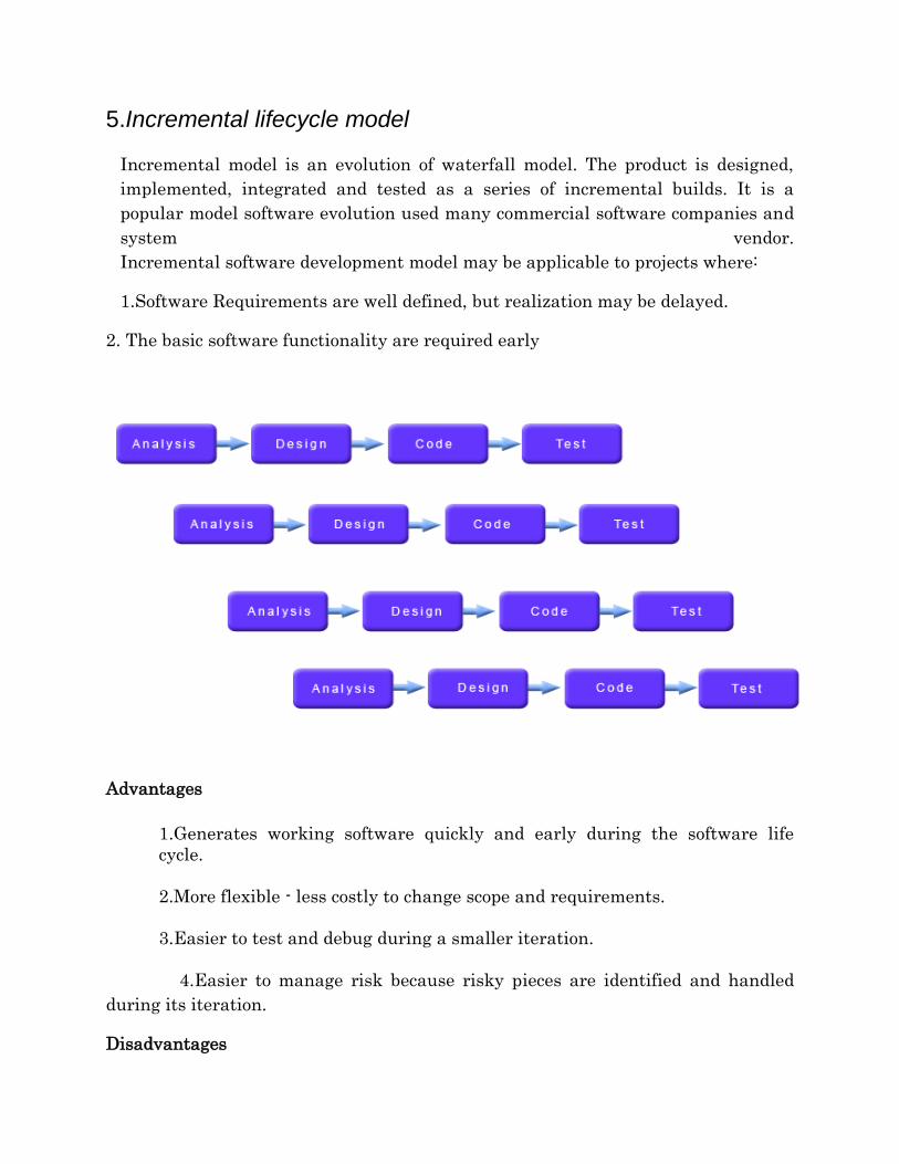
5.Incremental lifecycle model
Incremental model is an evolution of waterfall model. The product is designed,
implemented, integrated and tested as a series of incremental builds. It is a
popular model software evolution used many commercial software companies and
system vendor.
Incremental software development model may be applicable to projects where:
1.Software Requirements are well defined, but realization may be delayed.
2. The basic software functionality are required early
Advantages
Advantages
1.Generates working software quickly and early during the software life
cycle.
2.More flexible - less costly to change scope and requirements.
3.Easier to test and debug during a smaller iteration.
4.Easier to manage risk because risky pieces are identified and handled
during its iteration.
Disadvantages

1. Each phase of an iteration is rigid and do not overlap each other.
2. Problems may arise pertaining to system architecture because not all
requirements are gathered up front for the entire software life cycle.
Recommended