User ManualPLC-3
Communication
Adapter Module
(Cat. No. 1775-KA)
Allen�Bradley

Introduction 1�1. . . . . . . . . . . . . . . . . . . . . . . . . . . . . . . . . . . .
General 1�1. . . . . . . . . . . . . . . . . . . . . . . . . . . . . . . . . . . . . . . . . . .
About This Manual 1�1. . . . . . . . . . . . . . . . . . . . . . . . . . . . . . . . . . .
Module Description 1�4. . . . . . . . . . . . . . . . . . . . . . . . . . . . . . . . . .
Specifications 1�6. . . . . . . . . . . . . . . . . . . . . . . . . . . . . . . . . . . . . .
Applications 1�6. . . . . . . . . . . . . . . . . . . . . . . . . . . . . . . . . . . . . . . .
Installation 2�1. . . . . . . . . . . . . . . . . . . . . . . . . . . . . . . . . . . . .
General 2�1. . . . . . . . . . . . . . . . . . . . . . . . . . . . . . . . . . . . . . . . . . .
Hardware Installation 2�1. . . . . . . . . . . . . . . . . . . . . . . . . . . . . . . . .
Programmable Configuration Parameters 2�19. . . . . . . . . . . . . . . . . . .
Backup Configurations 2�27. . . . . . . . . . . . . . . . . . . . . . . . . . . . . . . .
Multiple 1775-KA Modules in One PLC-3 2�33. . . . . . . . . . . . . . . . . .
Data Highway Communication 3�1. . . . . . . . . . . . . . . . . . . . . .
General 3�1. . . . . . . . . . . . . . . . . . . . . . . . . . . . . . . . . . . . . . . . . . .
Some Terminology 3�1. . . . . . . . . . . . . . . . . . . . . . . . . . . . . . . . . . .
Levels of Programming 3�4. . . . . . . . . . . . . . . . . . . . . . . . . . . . . . . .
Data Transfers 3�6. . . . . . . . . . . . . . . . . . . . . . . . . . . . . . . . . . . . . .
Addressing Rules and Examples 4�1. . . . . . . . . . . . . . . . . . . .
General 4�1. . . . . . . . . . . . . . . . . . . . . . . . . . . . . . . . . . . . . . . . . . .
Number Systems 4�2. . . . . . . . . . . . . . . . . . . . . . . . . . . . . . . . . . . .
Addresses 4�3. . . . . . . . . . . . . . . . . . . . . . . . . . . . . . . . . . . . . . . . .
Symbols 4�4. . . . . . . . . . . . . . . . . . . . . . . . . . . . . . . . . . . . . . . . . .
PLC-3 Address Specifications 4�7. . . . . . . . . . . . . . . . . . . . . . . . . .
PLC/PLC-2 Address Specifications 4�10. . . . . . . . . . . . . . . . . . . . . . .
Remote Station Address Specifications 4�12. . . . . . . . . . . . . . . . . . . .
Expression 4�13. . . . . . . . . . . . . . . . . . . . . . . . . . . . . . . . . . . . . . . .
Editing 5�1. . . . . . . . . . . . . . . . . . . . . . . . . . . . . . . . . . . . . . . .
General 5�1. . . . . . . . . . . . . . . . . . . . . . . . . . . . . . . . . . . . . . . . . . .
Editing the Message Instruction 5�1. . . . . . . . . . . . . . . . . . . . . . . . . .
Allocating Memory 5�2. . . . . . . . . . . . . . . . . . . . . . . . . . . . . . . . . . .
Editing Message Procedures 5�2. . . . . . . . . . . . . . . . . . . . . . . . . . .
Table of Contents

Table of Contentsii
Message Procedure Commands 6�1. . . . . . . . . . . . . . . . . . . .
General 6�1. . . . . . . . . . . . . . . . . . . . . . . . . . . . . . . . . . . . . . . . . . .
Assignment Command 6�2. . . . . . . . . . . . . . . . . . . . . . . . . . . . . . . .
CREATE Command 6�5. . . . . . . . . . . . . . . . . . . . . . . . . . . . . . . . . .
DELETE Command 6�5. . . . . . . . . . . . . . . . . . . . . . . . . . . . . . . . . .
Execute 6�6. . . . . . . . . . . . . . . . . . . . . . . . . . . . . . . . . . . . . . . . . .
EXIT Command 6�6. . . . . . . . . . . . . . . . . . . . . . . . . . . . . . . . . . . . .
GOTO Command 6�7. . . . . . . . . . . . . . . . . . . . . . . . . . . . . . . . . . . .
IF Command 6�7. . . . . . . . . . . . . . . . . . . . . . . . . . . . . . . . . . . . . . .
ON_ERROR Command 6�8. . . . . . . . . . . . . . . . . . . . . . . . . . . . . . .
STOP Command 6�9. . . . . . . . . . . . . . . . . . . . . . . . . . . . . . . . . . . .
Functions 6�9. . . . . . . . . . . . . . . . . . . . . . . . . . . . . . . . . . . . . . . . .
Comments 6�11. . . . . . . . . . . . . . . . . . . . . . . . . . . . . . . . . . . . . . . . .
Error Reporting 7�1. . . . . . . . . . . . . . . . . . . . . . . . . . . . . . . . .
General 7�1. . . . . . . . . . . . . . . . . . . . . . . . . . . . . . . . . . . . . . . . . . .
Reporting Error Codes 7�1. . . . . . . . . . . . . . . . . . . . . . . . . . . . . . . .
Recovery from Errors 7�1. . . . . . . . . . . . . . . . . . . . . . . . . . . . . . . . .
Error Monitoring 7�2. . . . . . . . . . . . . . . . . . . . . . . . . . . . . . . . . . . . .
Programming Examples 8�1. . . . . . . . . . . . . . . . . . . . . . . . . . .
General 8�1. . . . . . . . . . . . . . . . . . . . . . . . . . . . . . . . . . . . . . . . . . .
Individual Commands 8�1. . . . . . . . . . . . . . . . . . . . . . . . . . . . . . . . .
Message Procedure 8�4. . . . . . . . . . . . . . . . . . . . . . . . . . . . . . . . . .
Computer to PC Communication 9�1. . . . . . . . . . . . . . . . . . . .
Introduction to Layered Communication 9�1. . . . . . . . . . . . . . . . . . . .
Full-Duplex vs Half-Duplex Protocol for the Data Link Layer 9�5. . . . .
Full-Duplex Protocol 10�1. . . . . . . . . . . . . . . . . . . . . . . . . . . . .
General 10�1. . . . . . . . . . . . . . . . . . . . . . . . . . . . . . . . . . . . . . . . . . .
Definition of Link and Protocol 10�1. . . . . . . . . . . . . . . . . . . . . . . . . . .
Full-Duplex Protocol 10�2. . . . . . . . . . . . . . . . . . . . . . . . . . . . . . . . .
Half-Duplex Protocol 11�1. . . . . . . . . . . . . . . . . . . . . . . . . . . . .
Half-Duplex Protocol 11�1. . . . . . . . . . . . . . . . . . . . . . . . . . . . . . . . .
Multidrop Link 11�1. . . . . . . . . . . . . . . . . . . . . . . . . . . . . . . . . . . . . .
Transmission Codes 11�2. . . . . . . . . . . . . . . . . . . . . . . . . . . . . . . . . .
Link-Layer Packets 11�4. . . . . . . . . . . . . . . . . . . . . . . . . . . . . . . . . .
Protocol Environment Definition 11�7. . . . . . . . . . . . . . . . . . . . . . . . . .
Half-Duplex Protocol Diagrams 11�13. . . . . . . . . . . . . . . . . . . . . . . . . .
Line Monitoring 11�20. . . . . . . . . . . . . . . . . . . . . . . . . . . . . . . . . . . . .

Table of Contents iii
The Network and Application Layer Protocol 12�1. . . . . . . . . . .
Network Layer 12�1. . . . . . . . . . . . . . . . . . . . . . . . . . . . . . . . . . . . . .
Application Layer 12�6. . . . . . . . . . . . . . . . . . . . . . . . . . . . . . . . . . . .
Message Formats A�1. . . . . . . . . . . . . . . . . . . . . . . . . . . . . . .
Introduction A�1. . . . . . . . . . . . . . . . . . . . . . . . . . . . . . . . . . . . . . . .
Basic Command Set A�8. . . . . . . . . . . . . . . . . . . . . . . . . . . . . . . . . .
PLC-3 Commands A�13. . . . . . . . . . . . . . . . . . . . . . . . . . . . . . . . . . .
Privileged Commands A�20. . . . . . . . . . . . . . . . . . . . . . . . . . . . . . . .
Error Codes B�1. . . . . . . . . . . . . . . . . . . . . . . . . . . . . . . . . . . .
General B�1. . . . . . . . . . . . . . . . . . . . . . . . . . . . . . . . . . . . . . . . . . .
Local Error Codes B�1. . . . . . . . . . . . . . . . . . . . . . . . . . . . . . . . . . .
Reply Error Codes B�1. . . . . . . . . . . . . . . . . . . . . . . . . . . . . . . . . . .
Remote Error Codes B�3. . . . . . . . . . . . . . . . . . . . . . . . . . . . . . . . .
Local and Reply Error Codes B�4. . . . . . . . . . . . . . . . . . . . . . . . . . .
Remote Error codes received from the 1771-KE/KF, 1771-KG,1771-KA, and 1774-KA Modules B�14. . . . . . . . . . . . . . . . . . . . . .
Remote Error Codes Received from the 1773-KA Module B�15. . . . . . .
Diagnostic Counter Block C�1. . . . . . . . . . . . . . . . . . . . . . . . .
Data Highway Port Counters C�1. . . . . . . . . . . . . . . . . . . . . . . . . . . .
Modem Port Counters C�2. . . . . . . . . . . . . . . . . . . . . . . . . . . . . . . .
Detailed Flowcharts D�1. . . . . . . . . . . . . . . . . . . . . . . . . . . . . .
Overview D�1. . . . . . . . . . . . . . . . . . . . . . . . . . . . . . . . . . . . . . . . . .
UART Sharing D�10. . . . . . . . . . . . . . . . . . . . . . . . . . . . . . . . . . . . . .
SLEEP and WAKEUP D�17. . . . . . . . . . . . . . . . . . . . . . . . . . . . . . . .
POWERUP D�18. . . . . . . . . . . . . . . . . . . . . . . . . . . . . . . . . . . . . . . .

Chapter
1
1�1
Introduction
The PLC–3 Communication Adapter Module (cat. no. 1775–KA) is anoptional module used in the PLC–3 main chassis or expander chassis. Itserves two purposes:
1. Interfacing the PLC–3 processor with the Allen–Bradley DataHighway
2. Interfacing the PLC–3 processor with an intelligent RS–232–Cdevice
This manual describes the installation, programming, and operation of the1775– KA module. This manual assumes that you are already thoroughlyfamiliar with the programming and operation of the PLC–3 processor. Itdoes not assume that you have any prior knowledge of the Allen–BradleyData Highway.
Organization
The remaining chapters of this manual are organized as follows:
Chapter 2 – describes installation of the 1775–KA module. Chapter 3 – presents concepts and terminology for operating the
1775–KA module on the Data Highway. Chapter 4 – presents general rules for specifying the data addresses you
use in message procedures. Chapter 5 – explains how you create and edit message procedures and
commands for the 1775–KA module. Chapter 6 – describes the command language you use in programming
message procedures. Chapter 7 – describes how the 1775–KA module detects and reports
various types of errors. Chapter 8 – presents detailed examples of 1775–KA module commands
and message procedures. Chapter 9 – introduces a layered approach to writing a driver to enable
a computer to communicate to the 1775–K’s RS–232–C channel.
General
About This Manual
IntroductionChapter 1
1�2
Chapter 10 – describes how to write a full–duplex line driver to enablea computer to communicate to the 1775–KA’s RS–232–C channel.
Chapter 11 – describes how to write a half duplex line driver to enablea computer to communicate to the 1775–KA’s RS–232–C channel.
Chapter 12 – describes the network and application layers of a softwaredriver to enable a computer to communicate to the 1775–KA’sRS–232–C channel.
Appendix A – shows detailed message formats. Appendix B – lists error codes reported by the 1775–KA, 1771–KA,
1771–KG, 1771– KE/KF, 1773–KA, and 1774–KA modules. Appendix C – lists diagnostic counters stored at the 1775–KA,
1771–KA, 1771–KG, 1771–KE/KF, 1773–KA and 1774–KA modules. Appendix D – gives detailed flow charts of an example of software
logic for implementing a full–duplex protocol.
Related Documentation
Read this manual in conjunction with the documentation listed inTable 1.A and Table 1.B. Table 1.A lists related PLC–3 documentationand Table 1.B lists related Data Highway documentation.
Table 1.ARelated PLC-3 Documentation
PublicationNumber
(Old/New No.)Title
1775-800/1775-6.7.1 PLC-3 Installation and Operations Manual
1775-801/1775-6.4.1 PLC-3 Programming Manual
1775-806/1775-6.5.3 I/O Scanner-Message Handling Module User'sManual
1775-900/1775-2.1 PLC-3 Controller Data Sheet
1775-901/1775-2.2 PLC-3 Main Processor Module Data Sheet
1775-902/-------- PLC-3 Memory Organization Data Sheet
1775-904/1775-2.4 Power Supply Data Sheet
1775-908/1775-2.6 PLC-3 Memory Modules Data Sheet
1775-910/1775-2.8 PLC-3 Main Chassis Data Sheet

IntroductionChapter 1
1�3
Table 1.BRelated Data Highway Documentation
PublicationNumber
(Old/New No.)Title
1770-810/1770-6.2.1 Data Highway Cable Assembly and Installation Manual
1771-801/1771-6.5.1 Communication Adapter Module (cat. no. 1771-KA)User's Manual
1771-802--------- Communication Controller Module (cat. no.1771-KC/KD)User's Manual
1771-811/1771-6.5.8 PLC-2 Family/RS-232C Interface Module (cat.no.1771-KG) User's Manual
1771/822/1771-6.5.15 Data Highway/RS-232-C Interface Module (cat. no.1771-KE/KF) User's Manual
1773-801/1773-6.5.2 PLC-4 Communication Interface Module (cat. no.1773-KA) User's Manual
1774-819/1774-6.5.8 Communication Adapter Module (cat. no. 1774-KA)User's Manual
6001-800/6001-6.5.1 6001 NET (For VMS) Network Communications SoftwareUser's Manual
6001-802/--------- 6001 NET (For RSX-11) Network CommunicationSoftware User's Manual
Terminology
In this manual you will read about the various commands the 1775–KAmodule can send and/or receive. To distinguish between commands, weuse some of the following terms:
a protected command can read or write only specified areas of PC datatable. A switch on the PLC, PLC–2 Family, and PLC–4 Controllersdetermines if the PC will accept only protected commands from anotherPC or an RS–232–C device. When you use a protected command, youmay have a limited area that you can read or write in the other station’smemory.
an unprotected command can read or write into any area of PC datatable. A switch on the PC that receives the commands determines if thePLC, PLC–2 Family, and PLC–4 controller will accept unprotectedcommands from another PC or an RS–232–C device.
privileged commands are sent by intelligent RS–232–C devices only.Such devices include computers and intelligent terminals.Allen–Bradley PC’s do not send privileged commands, but receive andreply to them. A privileged command can read or write into any area inthe memory of a PC, whether or not switches on the PC have been setto allow it to receive only protected commands. The term physical
IntroductionChapter 1
1�4
command is sometimes used synonymously to mean privilegedcommand.
non–privileged commands include any command that both PC’s andRS–232–C device can send. The non–privileged commands include theprotected write and unprotected read and write commands. Thenon–privileged commands are also referred to as “PLC/PLC–2 type”commands.
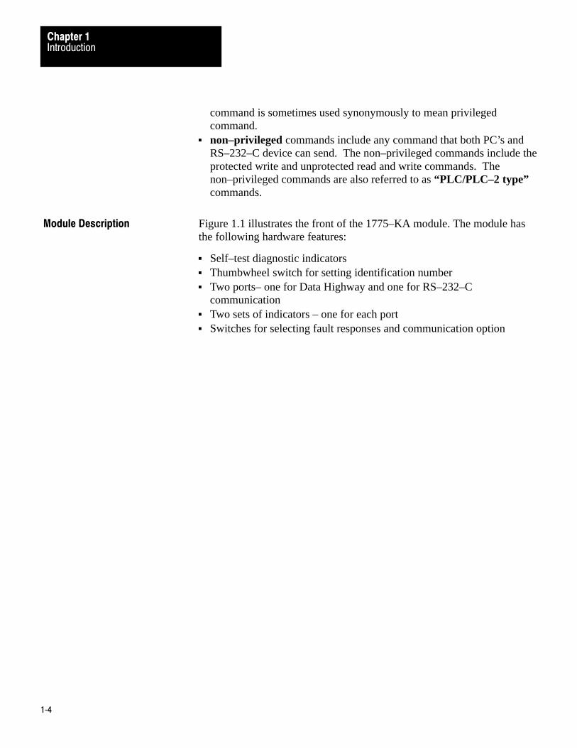
Figure 1.1 illustrates the front of the 1775–KA module. The module hasthe following hardware features:
Self–test diagnostic indicators Thumbwheel switch for setting identification number Two ports– one for Data Highway and one for RS–232–C
communication Two sets of indicators – one for each port Switches for selecting fault responses and communication option
Module Description
IntroductionChapter 1
1�5
Figure 1.1Communication Adapter Module (Cat. No. 1775-KA)
10000-I
PASSFAIL
SELFTEST
KA
DATAHWY
NO
MODEMINTERFACE
DATAHWY
XMTGRCVGRDYERRDIS
Self–Test Indicators
Thumbwheel Switch
RS–232–C port Indicators
Data Highway Port Indicators
RS–232–C Port
Data Highway Port
COMMUNICATION ADAPTER
XMTGRCVGERRDIS
In addition, the module provides the following software features:
Programmable configuration parameters Command language that allows for complex logic decisions, looping,
and nesting Symbolic representation of data and addresses Embedded arithmetic expressions and logic operations Decimal, octal, or BCD (binary coded decimal) data entry

IntroductionChapter 1
1�6
Table 1.C lists the specifications for the 1775–KA module.
Table 1.CModule Specifications
FunctionInterface the PLC-3 Processorwith the Allen-Bradley DataHighway and/or with an RS-232-Cdevice
Communication RateTo Data Highway - 57.6 kilobaudrecommended
To modem-programmable from 110baud to 19.2 kilobaud
Backplane Power Requirement2.5A max. @ +5V DC
Ambient Temperature Rating00 o 600C (operational)-400 to 850C (storage)
LocationSingle slot in PLC-3 main chassisor expander chassis
CablingTo Data Highway-Data Highwaydropline cable (Cat.no.1770-CD orequivalent
Humidity Rating5% to 95% (without condensation)
Communication PortsData Highway
RS-232-C Modem
To modem-Modem interface cable(cat. no. 1775-CKA or equivalent)
As already mentioned, the 1775–KA module serves two main purposes:
Interfacing the PLC–3 processor with the Allen–Bradley Data Highway Interfacing the PLC–3 processor with an intelligent RS–232–C device
You can use the module for both of these purposes simultaneously.
In Data Highway applications, the module serves as an interface betweenthe PLC–3 programmable controller and the Allen–Bradley DataHighway. The Data Highway is an industrial communication networkthat links together as many as 64 distinct stations. Each station can consistof a programmable controller (such as the PLC–3), a computer, or anintelligent RS–232–C device. The central trunkline of the Data Highwaymay be up to 10,000 feet long, and each station may be as far as 100 feetfrom the trunkline. Figure 1.2 gives an example of a Data Highwayconfiguration.
Specifications
Applications

IntroductionChapter 1
1�7
Figure 1.2Example Data Highway Configuration
PC
PC
PC
PC
PC
Allen-BradleyData Highway
1775-KA Module
NOTE: All PCs are Allen-Bradley
Up to 64 Stations
PLC-3Controller
10001–I

IntroductionChapter 1
1�8
The PLC–3 can support multiple 1775–KA modules in the same PLC–3chassis. This provides the PLC–3 with concurrent access to severalindependent Data Highways.
The 1775–KA module can also serve as an interface between the PLC–3programmable controller and an intelligent RS–232–C compatible deviceor any Allen–Bradley PC and its Data Highway module. Some examplesof this application of the module are the following:
Interfacing two PLC–3 controllers through a modem link Interfacing a PLC–3 controller with a computer (either directly or
through modems) Interfacing a PLC–3 controller with a remote Data Highway through a
modem link Interfacing a PLC–3 controller as a slave station on a multipoint
modem link Interfacing a PLC–3 controller on a point–to–point link with PLC–2
Family processor through a 1771–KG module (The 1772–LR processoris not supported in this configuration.)
Figure 1.3 shows the 1775–KA module in a typical modem application.
Figure 1.3Typical Modem Application
Modem
Computer
1775-KA Module
NOTE: Modems requiredonlyfor distances greaterthan 50 feet.
10002–I
PLC-3Controller
Modem

Chapter
2
2�1
Installation
This chapter describes installation of the 1775–KA module in two phases:
Installing hardware Programming configuration parameters through the PLC–3 LIST
function
Please read the entire manual carefully before attempting to install themodule.
For best results when installing the 1775–KA module, proceed in theorder indicated below.
Switch Settings
The 1775–KA module has a number of hardware switches that must be setbefore the module can be installed in the PLC–3 processor. There is athumbwheel switch on the front edge of the module and a group of optionswitches on the bottom edge.
Thumbwheel Switch
Figure 2.1 shows a thumbwheel switch on the front edge of the 1775–KAmodule. This thumbwheel switch designates the number used by thePLC–3 processor to distinguish one 1775–KA module from another.Rotate the thumbwheel to select the desired identification number.
General
Hardware Installation

InstallationChapter 2
2�2
Figure 2.1Front View of 1775-KA Module
10003-I
XMTGRCVGRDYERRDIS
Self–Test Indicators
Thumbwheel Switch
RS–232–C port Indicators
Data Highway Port Indicators
RS–232–C Port
Data Highway Port
COMMUNICATION ADAPTER
PASSFAIL
SELFTEST
KA
DATAHWY
XMTGRCVGERRDIS
NO
MODEMINTERFACE
DATAHWY
If there is only one 1775–KA module in the PLC–3 chassis, set itsthumbwheel switch to the number 1. If there are multiple 1775–KAmodules in the same PLC–3 chassis, set their thumbwheel switches toconsecutive numbers, starting with the number 1. You may write theselected number in the space provided beside the thumbwheel switch.

InstallationChapter 2
2�3
CAUTION: To guard against unpredictable operation of thePLC–3 processor, do not change the setting on any thumbwheelswitch while the 1775–KA module is powered–up.
Option Switches
Figure 2.2 shows a set of four option switches on the bottom edge of the1775– KA module. Switches 1 and 2 are used when the PLC–3 controlleris programmed to operate in a backup configuration. Switch number 1determines whether or not a fault in the 1775–KA module will cause theprimary PLC–3 controller to switch over to the backup PLC–3. Switchnumber 2 determines whether or not the 1775–KA module will disable itsData Highway port when the PLC–3 becomes deactive. Switch 3 is forRS–232–C communication. Switch 4 is reserved for future use andshould always be left open (up, or off). Use Table 2.A below to determinethe appropriate switch setting:
Figure 2.2Option Switches

InstallationChapter 2
2�4
Table 2.A1775-KA Switch Settings
If thisswitch: Is: Then
1 OPEN the PLC will switch over to backup whenever one of thefollowing fault conditions occurs:1. The 1775-KA module tries to hold control of the PLC-3
backplane for more than 138 microseconds.
2. The 1775-KA module experiences a execution timeout of more than 32 milliseconds
3. The 1775-KA module experiences an internal stack overflow4. The 1775-KA module experiences severe Data Highway
communication problems.
1 CLOSED the primary PLC-3 will not switch to backup when a fault occurswith the 1775-KA module.
2 OPEN the 1775-KA module will disable is Data Highway portwhenever the primary PLC-3 controller becomes deactive. Themodule will no longer be able to transmit or receivemessagesthrough its Data Highway port.
Also, setting switch 2 to open enables the backup operationfeature.
2 CLOSED the Data Highway port on the module will remain active if theprimary PLC-3 becomes deactive.
3 OPEN the module may be connected up to 7,000 cable feet away froma 1771-KF, a 1771-KG, 1773-KA or another 1775-KA module.In addition to setting switch 3 to the open position, you mustalso set switch 2 to closed position. This makes pin 25 on theRS-232-C port of the 1775-KA module active (refer to figures2.8 to 2.10). Note that switch 3 must always be closed forcommunication with an RS-232-C device other than a1771-KF, 1771-KG, 1773-KA, or 1775-KA module.
3 CLOSED the MODEM INTERFACE port of the 1775-KA module may beconnected to a standard RS-232-C device that is located within50 cable feet of the module.
4 OPEN Switch 4 is reserved for future use and should always be leftopen.
Module Placement
After setting the thumbwheel switch, insert the module into any one of themodule slots in the PLC–3 processor chassis. Whenever you power–upthe processor, the module will receive power also.
InstallationChapter 2
2�5
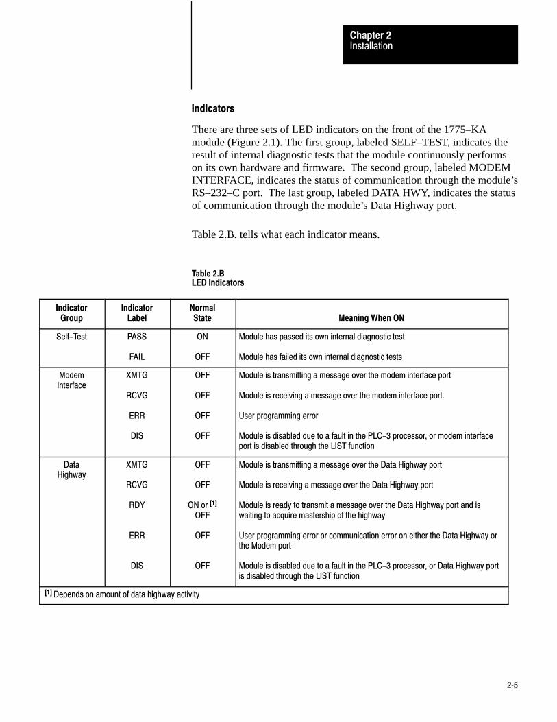
Indicators
There are three sets of LED indicators on the front of the 1775–KAmodule (Figure 2.1). The first group, labeled SELF–TEST, indicates theresult of internal diagnostic tests that the module continuously performson its own hardware and firmware. The second group, labeled MODEMINTERFACE, indicates the status of communication through the module’sRS–232–C port. The last group, labeled DATA HWY, indicates the statusof communication through the module’s Data Highway port.
Table 2.B. tells what each indicator means.
Table 2.BLED Indicators
IndicatorGroup
IndicatorLabel
NormalState Meaning When ON
Self-Test PASS
FAIL
ON
OFF
Module has passed its own internal diagnostic test
Module has failed its own internal diagnostic tests
ModemInterface
XMTG
RCVG
ERR
DIS
OFF
OFF
OFF
OFF
Module is transmitting a message over the modem interface port
Module is receiving a message over the modem interface port.
User programming error
Module is disabled due to a fault in the PLC-3 processor, or modem interfaceport is disabled through the LIST function
DataHighway
XMTG
RCVG
RDY
ERR
DIS
OFF
OFF
ON or [1]
OFF
OFF
OFF
Module is transmitting a message over the Data Highway port
Module is receiving a message over the Data Highway port
Module is ready to transmit a message over the Data Highway port and iswaiting to acquire mastership of the highway
User programming error or communication error on either the Data Highway orthe Modem port
Module is disabled due to a fault in the PLC-3 processor, or Data Highway portis disabled through the LIST function
[1] Depends on amount of data highway activity

InstallationChapter 2
2�6
Data Highway Cable Connections
There are two cable connectors, or ports, on the front of the 1775–KAmodule (Figure 2.1). The bottom port, labeled DATA HWY., is forconnection to the Allen–Bradley Data Highway. If you are using the1775–KA module in a Data Highway application, plug the Data Highwaydropline cable into this port. For details on the installation of the DataHighway cable, refer to the Data Highway Cable Assembly andInstallation Manual (publication 1770–810).
RS-232-C Cable Connections
The RS–232–C port, labeled MODEM INTERFACE on the 1775–KAmodule, can interface with any RS–232–C device that is capable ofunderstanding and generating the communication protocol described inthis chapter. Some typical RS–232–C applications are:
Interfacing two PLC–3 controllers through a modem link (Figure 2.3)
Figure 2.3Linking Two PLC-3 Controllers
Modem
1775-KA Module
10004–I
PLC-3 Controller
Modem
1775-KA Module
PLC-3 Controller
NOTE: Modems required onlyfor distances greaterthan 50 feet.

InstallationChapter 2
2�7
Interfacing a PLC–3 controller with a computer, either directly orthrough modems (Figure 2.4)
Figure 2.4Linking a PLC-3 Station to a Computer
Modem
Computer
1775-KA Module
10005–I
PLC-3Controller
Modem

InstallationChapter 2
2�8
Interfacing a PLC–3 controller with a remote Data Highway through amodem link (Figure 2.5)
Figure 2.5Linking a PLC-3 Station to a Remote Data Highway
Modem
1775-KA Module
10006–I
PLC-3Controller
Modem
PC
PC
PC
PC
PC
Allen-BradleyData Highway
NOTE: All PCs are Allen-Bradley
Up to 64 Stations
1771-KF Module

InstallationChapter 2
2�9
Interfacing a PLC–3 controller to a PLC–2 Family processor through a1771–KG module in a point–to–point link (Figure 2.6)
Figure 2.6Linking a PLC-3 to PLC-2 Family Controller
PLC–3 Controller
1775–KA Module
PLC–2 Controller
1771–KG Module
Modem
Modem
NOTE: Modems required only fordistances greater than 50 feet.
10007-I
InstallationChapter 2
2�10
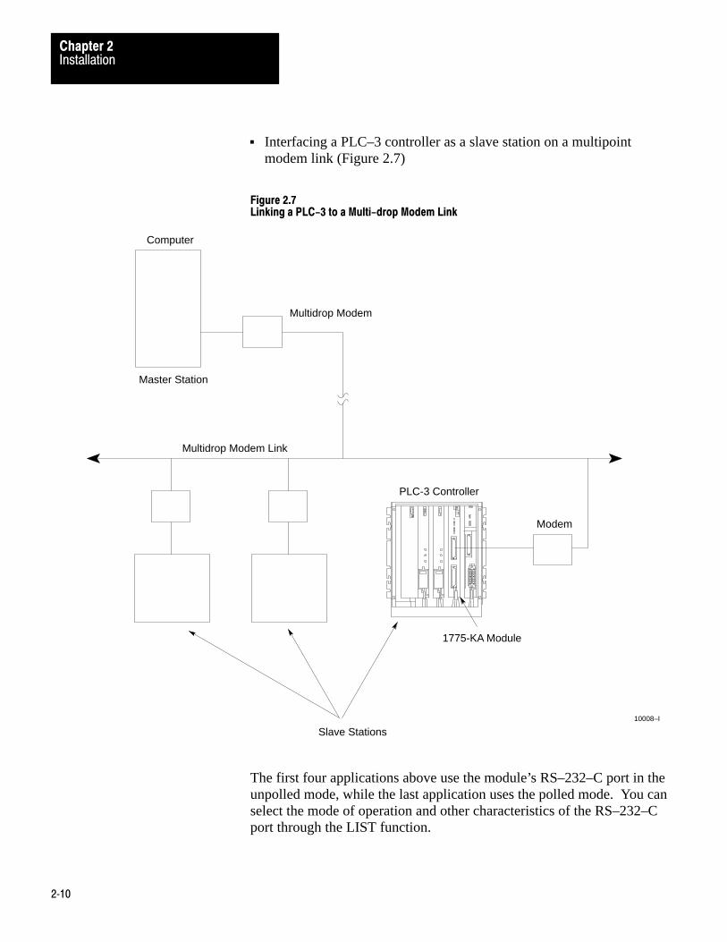
Interfacing a PLC–3 controller as a slave station on a multipointmodem link (Figure 2.7)
Figure 2.7Linking a PLC-3 to a Multi-drop Modem Link
Modem
1775-KA Module
10008–I
PLC-3 Controller
Multidrop Modem
Computer
Master Station
Multidrop Modem Link
Slave Stations
The first four applications above use the module’s RS–232–C port in theunpolled mode, while the last application uses the polled mode. You canselect the mode of operation and other characteristics of the RS–232–Cport through the LIST function.
InstallationChapter 2
2�11
Each mode of operation requires a different communication protocol. Theunpolled mode uses full–duplex protocol (chapter 10) while the polledmode uses half–duplex protocol (chapter 11). In general, full–duplexprotocol gives faster data throughput but is more difficult to implement;half–duplex protocol is easier to implement but gives slow datathroughput.
NOTE: In other Data Highway documentation, full–duplex protocolmight be referred to as DFI protocol, and half–duplex protocol might bereferred to as polled–mode protocol.
Hardware Interface
The modem interface is based on EIA RS–232–C and related standards.This interface should be compatible with most dedicated and dial–upnetwork RS–232 modems.
Mechanical
The RS–232 connector on the 1775–KA module is a 25–pin maleconnector.
Electrical
Input and output levels on the RS–232 connector conform to theRS–232–C standard. The transmitter has increased capability to drive a7,000 foot isolated lines. This number depends on baud rate and refers toonly direct wire connections. (Refer to Table 2.C.)

InstallationChapter 2
2�12
Table 2.CDistance Rate Variations
Distancein feet
MaximumBaud Rate
1,000 19,200
2,000 9,600
3,000 9,600
4,000 4,800
5,000 4,800
6,000 2,400
7,000 2,400
The receiver is designed to sense the signal generated by a similartransmitter, and is electrically isolated from all other circuitry on themodule. It consists of an opto–isolater circuit with an input and returnconnection at the RS–232 connector. All other signals on the RS–232connector are driven and received by standard RS–232 interface circuits,and have a maximum drive capability of 50 feet.
InstallationChapter 2
2�13
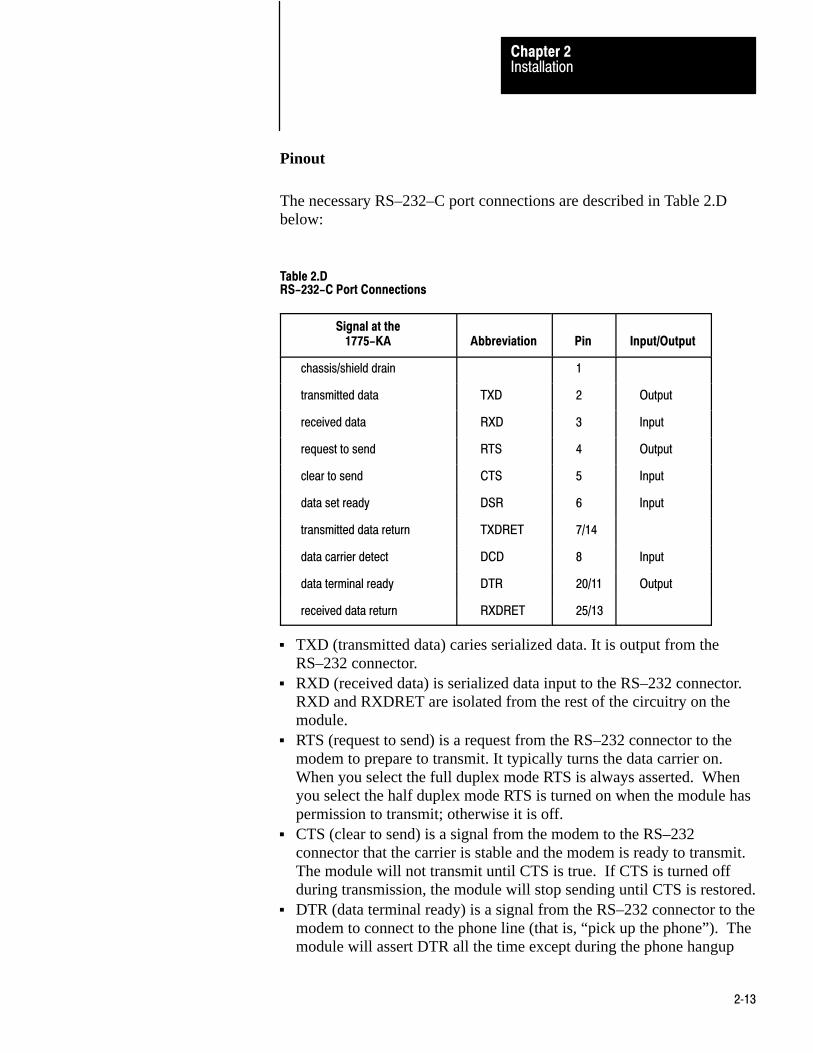
Pinout
The necessary RS–232–C port connections are described in Table 2.Dbelow:
Table 2.DRS-232-C Port Connections
Signal at the1775-KA Abbreviation Pin Input/Output
chassis/shield drain 1
transmitted data TXD 2 Output
received data RXD 3 Input
request to send RTS 4 Output
clear to send CTS 5 Input
data set ready DSR 6 Input
transmitted data return TXDRET 7/14
data carrier detect DCD 8 Input
data terminal ready DTR 20/11 Output
received data return RXDRET 25/13
TXD (transmitted data) caries serialized data. It is output from theRS–232 connector.
RXD (received data) is serialized data input to the RS–232 connector.RXD and RXDRET are isolated from the rest of the circuitry on themodule.
RTS (request to send) is a request from the RS–232 connector to themodem to prepare to transmit. It typically turns the data carrier on.When you select the full duplex mode RTS is always asserted. Whenyou select the half duplex mode RTS is turned on when the module haspermission to transmit; otherwise it is off.
CTS (clear to send) is a signal from the modem to the RS–232connector that the carrier is stable and the modem is ready to transmit.The module will not transmit until CTS is true. If CTS is turned offduring transmission, the module will stop sending until CTS is restored.
DTR (data terminal ready) is a signal from the RS–232 connector to themodem to connect to the phone line (that is, “pick up the phone”). Themodule will assert DTR all the time except during the phone hangup

InstallationChapter 2
2�14
sequence. Some modem will not respond to DTR until the phone rings,while others will always pick up the phone whether it is ringing or not.
DSR (data set ready) is a signal from the modem to the RS–232connector that the phone is off–hook. (It is the modem’s answer toDTR). The module will not transmit or receive unless DSR is true. Ifthe modem does not properly control DSR, or if no modem is used,DSR must be jumpered to an RS–232 high signal at the RS–232connector. (It can be jumpered to DTR).
DCD (data clear ready) is a signal from the modem to the RS–232connector that the carrier from another modem is being sensed on thephone line. It will not be asserted unless the phone is off–hook. Datawill not be received at the RS– 232 connector unless DCD is true. Inthe full duplex mode the module will not transmit unless DCD is true.If the modem does not properly control DCD, or if a modem is notbeing used, DCD must be jumpered to DTR at the RS–232 connector.
TXDRET (transmitted data return) is the return signal for TXD. It isconnected to module logic ground through a resistor.
RXDRET (received data return) is the return signal for RXD. It isconnected to the isolated receiver, and is isolated from all othercircuitry on the module.
Connections To The RS–232 Port
Connection to the RS–232 port of the 1775–KA can be one of two types:
Short line (50 feet or less) Isolated long line (between 50 and 7,000 feet)
For short lines, the connection may be either direct or through modems.
You connect an intelligent, RS–232–C compatible device to an interfacemodule by attaching a cable to both the device and to the module socketlabeled RS– 232–C CHANNEL. The RS–232–C device may be anotherAllen–Bradley communication interface module or anothermanufacturer’s device. For a standard RS–232–C connection, the cableshould be no longer than 50 feet. If your RS–232–C device has anAllen–Bradley line driver/receiver, you may use a cable up to 7,000 feetlong.
If you want to connect the 1775–KA module to a 1771–KG or1771–KE/KF module through the RS–232–C channel, use the cablingpinout diagram (Figure 2.8) to construct your own cable.

InstallationChapter 2
2�15
Figure 2.8Connection to Allen-Bradley 1771-KG or 1771-KE/KF Module
1
2
7
3
25
4
5
6
8
20
1
3
13
2
14
4
5
6
8
11
Connect the Shield at One End Only
RS–232–CCHANNELConnectorof 1775–KAModule
RS–232–CCHANNELConnectorof 1771–KGor 1771–KE/KFModule
Conductors 2 and 7, 3 and 25 must be twisted pairs for distances longerthan 50 feet.
Set switch 3 (on the 1775–KA) OFF when the module is communicatingwith another Allen-Bradley device. 10009–I
1
2
1
2
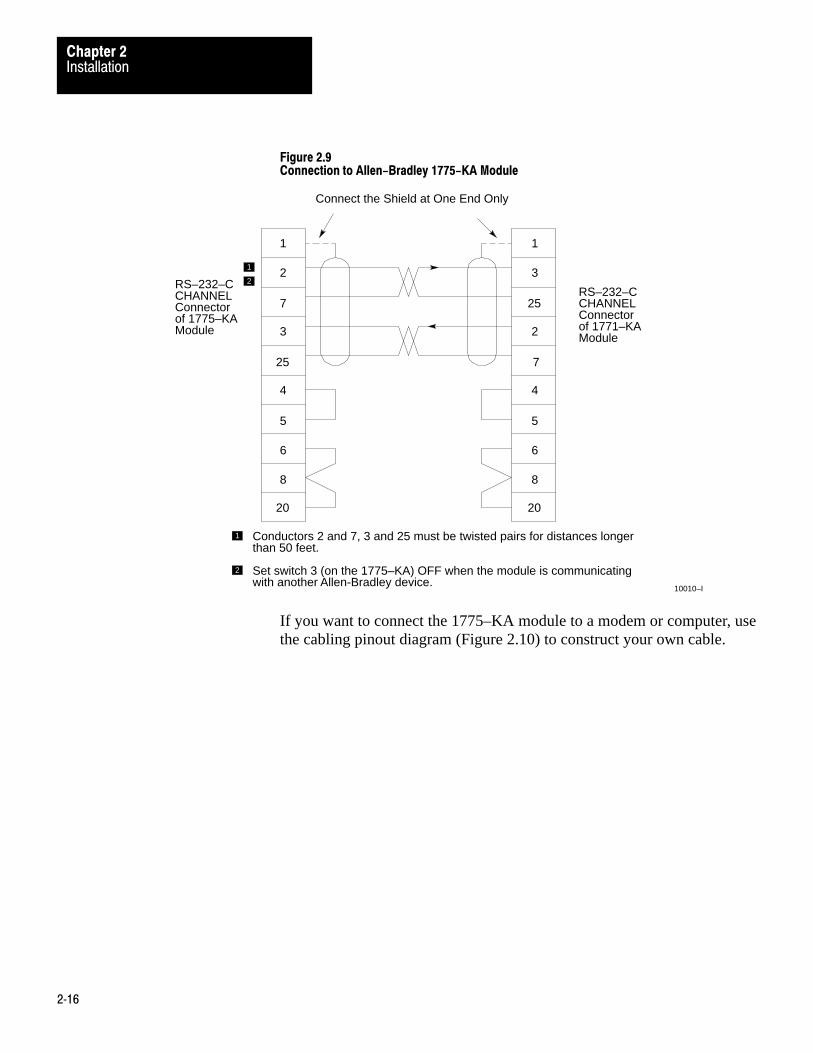
If you want to connect the 1775–KA module to a 1775–KA modulethrough the RS– 232–C channel, use the cabling pinout diagram(Figure 2.9) to construct your own cable.
InstallationChapter 2
2�16
Figure 2.9Connection to Allen-Bradley 1775-KA Module
1
2
7
3
25
4
5
6
8
20
1
3
25
2
7
4
5
6
8
20
Connect the Shield at One End Only
RS–232–CCHANNELConnectorof 1775–KAModule
RS–232–CCHANNELConnectorof 1771–KA
Conductors 2 and 7, 3 and 25 must be twisted pairs for distances longerthan 50 feet.
Set switch 3 (on the 1775–KA) OFF when the module is communicatingwith another Allen-Bradley device.
10010–I
1
2
1
2
Module
If you want to connect the 1775–KA module to a modem or computer, usethe cabling pinout diagram (Figure 2.10) to construct your own cable.

InstallationChapter 2
2�17
Figure 2.10Connection to user-Supplied Modem or RS-232-C Device
1
2
3
4
5
6
7
8
20
25
10011–I
1
User–suppliedModerm orRS–232–CDevice
Protective Ground
Transmitted Data
Received Data
Request to Send
Clear to Send
Data Set Ready
Signal Ground
Line Signal Detect
Data Terminal Ready
Received DataReturn
RS–232–CCHANNEL Connector of1775–KA Module
Set Switch 3 ON to ground pin 25.1
Private lines are permanently connected phone lines used with modems.Dialup is not needed. Usually the modem hold the handshake lines in theproper states.
The RS–232 port can be connected to standard American dial–up modemsand some European modems. Other European standards specify that theDTR signal will cause the modem to answer the phone whether it isringing or not, causing the phone to always be “busy”. Since the modemport asserts DTR while waiting for a call, it cannot be used with suchmodems.
The types of dial–up network modems that can be used are classified intothe following types:
Manual: these are typically acoustically coupled modems. Theconnection is established by human operators at both ends, who theninsert the handset into couplers to connect the computers.
DTE–controlled answer: these unattended modems are directlyconnected to the phone lines. A module controls the modem via the

InstallationChapter 2
2�18
DTR, DSR, and DCD signals. It incorporates timeouts and tests toproperly operate these types of modems.
Auto–answer: these modems have self–contained timeouts and tests,and can answer and hangup the phone automatically.
The modem port has no means to control an auto–dial modem, although itis possible that it can be used in conjunction with a separate auto–dialer.
Answering
The module continually asserts DTR when it is waiting for a call. Underthis condition the modem will answer a call and assert DSR as soon asringing is detected. The module does not monitor the RING indicator inthe RS–232 interface. Once DSR is detected the module starts a timer(around 10 seconds) and waits for the DCD signal. When DCD isdetected communication can start.
If DCD is not detected within the timeout, the module turns DTR off. Thiscauses the modem to hangup and break the connection. When the hangupis complete the modem drops the DSR line. This causes the module toreassert the DTR line and wait for another call. This feature protectsaccess to the phone if someone calling a wrong number reaches thisstation.
Once DCD is detected the module continues to monitor the DCD line. IfDCD goes false the timeout is restarted. If DCD is not restored within thetimeout, the hangup sequence is initiated. This feature allows the remotestation to re–dial in the event the connection is lost by the phone network.
Note that this handshaking is necessary to guarantee access to the phoneline. If this handshaking protocol is defeated by improper selection ofmodem options, or jumpers at the connectors, the modem may answer acall, but if the connection is lost the modem will not hangup. It will beimpossible for the remote station to reestablish the connection because itwill get a busy signal.
Character Transmission
Data is sent serially over the RS–232 interface, one eight–bit byte at atime. The transmission format conforms to ANSI X3.16, CCITT V.4, andISO 1177, with the exception that the parity bit is retained whileextending the data length to eight bits.
InstallationChapter 2
2�19
The transmission format may be summarized as follows:
start bitdata bit 0data bit 1data bit 2data bit 3data bit 4data bit 5data bit 6data bit 7even parity bit (optional)one stop bit
The 1775–KA module selects baud and parity through the LIST function(section titled Programmable Configuration Parameters).
A number of installation parameters for the 1775–KA module can beprogrammed through the PLC–3 LIST function.
The LIST function words by presenting you with a series of lists, ormenus, that allows you to select and establish the module’s operatingparameters. Each option in an upper–level menu represents a submenu ofmore detailed options. This process continues until you have selectedenough options to define a single parameter in full detail. Figure 2.11illustrates the menu structure of LIST. To return to the preceding (nexthighest) level of LIST, press the ENTER key without making a new entry.
Programmable ConfigurationParameters

InstallationChapter 2
2�20
Figure 2.11LIST Menu for 1775-KA Module
System Mode1 Test–Monitor2 Run Monitor3 Program Load4 Remote Enable5 System Status6 *Module StatusEnter Next > Modules
1 01 1775–ME8 A/A1775–ME8 A/A1775–L3 A/A1775–S4A B/A1775–KA A/E1775–LX A/A1775–LX A/A1775–S4B B/A1775–S4B B/A
2 023 034 045 056 067 078 089 09ENTER NEXT > Data Hwy Comm
Adapter – 01Chassis 0 Slot 01 Module Options2 Data Highway Port3 Modem PortEnter Next >
KA–01 Data Highway Port1 Enable/Disable Port2 Station Number3 Baud RateEnter Next >
KA–01 Modem Port1 Enable/Disable Port2 Station Number3 Baud Rate4 Communication Mode5 Even Parity6 *Send Embedded
ResponsesEnter Next >
KA–01 Module Options1 Timeout2 *Send Unprotected3 Accept Upload/Download4 Accept W rites
5 Backup Operation6 PLC–2 MaskENTER NEXT >
KA–01 Module OptionsTimeoutEnter Timeout >
KA–01 Data Highway Port Enable1 Enable2 *DisableEnter Next >
KA–01 Data Highway PortStation NumberEnter Station Number >
KA–01 Data Highway Port Baud Rate1 384002 *57600Enter Next >
KA–01 Modem Port Enable1 Enable2 *DisableEnter Next >
KA–01 Modem PortStation – 377Enter Station Number >
KA–01 Modem Port Baud Rate1 1102 3003 6004 *12005 24006 48007 96008 19200Enter Next >
KA–01 Modem Port Communication Mode1 *Unpolled Mode2 Polled – Subscriber ModeEnter Next >
Toggle selection – select this number to enableor disable the option.
NOTE: Those selections shown in bold type affectthe operation of the module; the LIST displayshows an asterisk (*) to indicate when anoption is enabled. The selections not shown inbold type only cause a movement to another levelof LIST. This selections indicated in this figure areselected by default at the initial power–up.
= 50/10 sec
= 377
1
11
1
11
1
1
10012–I

InstallationChapter 2
2�21
You access the LIST function by typing the word LIST and press theENTER key. After accessing the LIST function, select option 6 MODULESTATUS from the SYSTEM–MODE MENU. LIST then presents youwith a menu that describes the modules in your system. The menu variesaccording to the modules in your PLC–3. A typical menu might be:
MODULES:1 01 1775–ME8 A/A2 02 1775–ME8 A/A3 03 1775–L3 A/A4 04 1775–S4A B/A5 05 1775–KA A/E6 06 1775–LX A/A7 07 1775–LX A/A8 08 1775–S4B B/A9 09 1775–S4B B/AENTER NEXT<
Under MODULE STATUS, select the option for 1775–KA. At this point,LIST presents you with the following menu for the 1775–KA module:
DATA HWY COMM. ADAPTER–nnCHASSIS cc SLOT ss1 MODULE OPTIONS2 DATA HIGHWAY PORT3 MODEM PORTENTER NEXT>
In the above and all following menus, “nn” represents the thumbwheelsetting of the 1775–KA module, “cc” represents the chassis number, and“ss” represents the number of the chassis slot containing the module. Formore information about the LIST function, refer to Publication 1775–800,PLC–3 Installation and Operation Manual.
Module Options
Selecting option 1 MODULE OPTIONS from the above menu (sectiontitled Programmable Configuration Parameters) causes LIST to presentthe following menu:
KA – nn MODULE OPTIONS1 TIMEOUT2 SEND UNPROTECTED

InstallationChapter 2
2�22
3 ACCEPT UPLOAD/DOWNLOAD4 ACCEPT WRITES5 BACKUP OPERATION6 PLC–2 MASKENTER NEXT>
This menu allows you to select options that apply equally to both themodem port and the Data Highway port of the 1775–KA module. Theseoptions are described below.
Timeout
The timeout is the maximum amount of time that the 1775–KA modulewill wait for another station to reply to one of its messages. The allowedentries are 0 to 9999, expressed in increments of 1/10 second. LISTdisplays the timeout as “xxxx/10 SEC”. Thus, if you enter a timeoutvalue of 100, the timeout period will be 10 seconds and will be displayedas 100/10 SEC.
The same timeout setting applies to both the Data Highway and themodem ports. The default timeout setting is 5 seconds, displayed as 50/10SEC.
The timeout period applies to each individual transmission. Because oftheir size, some messages consist of several packets of data. Eachmessage packet requires a separate transmission. Therefore, the timeoutis restarted for each packet.
If the 1775–KA module waits longer than the timeout period for a reply toone of its messages, it generates an error code of 37 (Appendix B). Themodule then resumes executing the current message procedure at the linefollowing the one in which the timeout occurred.
LIST keeps you at this timeout level and allows you to make repeatedchanges to the timeout value. To return to the preceding (next highest)level of LIST, press the ENTER key again without entering a new timeoutvalue.
InstallationChapter 2
2�23
Send Unprotected
This option determines whether or not the 1775–KA module will be ableto send unprotected command messages to other stations. If you selectoption 2 SEND UNPROTECTED, the 1775–KA module will be able tosend both protected and unprotected commands.
You can use an unprotected command to read or write to any area of a PCdata table. You can use a protected command, however, to write only tothose areas of a PC data table specified by the PC that receives thecommand. For more information on protected and unprotectedcommands, see section titled Access Privileges, chapter 3.
If you do not select (enable) this option, the module will be able totransmit only protected commands. At initial power–up, the moduleenables the SEND UNPROTECTED option by default.
Accept Upload/Download
This option determines whether or not the 1775–KA module will be ableto execute upload and download commands sent to it by a computer. Ifoption 3 ACCEPT UPLOAD/DOWNLOAD is selected, the module willbe able to execute both upload and download commands. You send asequence of upload and download commands when you want to transferthe memory of the PLC–3 to another station, or to transfer the memory ofanother station to a PLC–3.
If this option is not selected (enabled) the module will not be able toexecute either of these two types of commands. For a description ofupload and download commands, refer to Appendix A. At initialpower–up, the module enables the ACCEPT UPLOAD/DOWNLOADoption by default.
Accept Writes
This option determines whether or not the 1775–KA module will acceptwrite–type command messages from a remote Data Highway station whenthe local PLC–3 processor’s memory protect keyswitch is on. If option 4ACCEPT WRITES is selected, the module will accept write commandsregardless of the setting of the PLC–3’s memory protect keyswitch. Ifthis option is not selected (enabled) the module will accept writecommands when the memory protect keyswitch is off but will reject thewrite commands and return an error code of 86 if the memory protect

InstallationChapter 2
2�24
keyswitch is on. At initial power–up, the module enables the ACCEPTWRITES option by default.
Backup Operation
This option determines whether or not a pair of 1775–KA modules willprovide backup for each other. Enable option 5 (BACKUP OPERATION)for both the primary and backup 1775–KA modules to enable backupoperation as described in section 2.3 (backup configurations). If youmake no selection for option 5, backup operation is disabled by default.The revision C or earlier version of the module does not have theBACKUP OPERATION option.
PLC–2 Mask
This option determines whether or not the 1775–KA module will maskout the upper octal digit of the source address when receiving a PLC–2type command from another station. If you enable option 6(PLC–2–MASK) the module mask out the upper digit of the address forselecting the input file. This causes stations with common second andthird digits of their address to access the same input file. For example,stations 023, 123, 223, and 323 would all access input file 023.
If you disable option 6, each station accesses a unique input file with thesame number as the station number. For example, station 123 wouldaccess input file 123; station 223 would access input file 223. If youmake no selection for option 6, the PLC–2 MASK option is disabled bydefault. The revision D or earlier version of the module does not have thePLC–2 MASK option.
Data Highway Port
Selecting option 2 DATA HIGHWAY PORT from the above menu(section titled Programmable Configuration Parameters) causes LIST topresent the following menu:
KA – nn DATA HIGHWAY PORT1 ENABLE/DISABLE PORT2 STATION NUMBER3 BAUD RATEENTER NEXT>

InstallationChapter 2
2�25
This menu allows you to select options that apply to only the DataHighway port of the 1775–KA module. These options are describedbelow.
Enable/Disable Port
This option determines whether or not the 1775–KA module cancommunicate over the Data Highway. you must select the ENABLEoption in order to allow communication to take place. If you make noselection, the PLC–3 disables this port by default.
Note, however, that you cannot use LIST to change any other parametersof the Data Highway port unless you first DISABLE the port. After youare done entering parameters through LIST, don’t forget to ENABLE theData Highway port again.
Station Number
This option selects the number by which the PLC–3 station is identifiedon the Data Highway. Allowable station numbers are 1 to 376 octal. Inparticular, note that the number 377 is illegal. Entering 377 as the stationnumber will automatically disable the 1775–KA module, and you will notbe able to ENABLE it again through LIST until you select a differentstation number. If you make no selection, the PLC–3 assumes the illegaladdress 377 by default.
Baud Rate
This option specifies the communication rate over the Data Highway. Acommunication rate of 57,600 baud is recommended.
Modem Port
Selecting option 3 MODEM PORT from the above menu (section titledProgrammable Configuration Parameters) causes LIST to present thefollowing menu:
KA–NN modem port1 ENABLE/DISABLE PORT2 STATION NUMBER3 BAUD RATE4 COMMUNICATION MODE

InstallationChapter 2
2�26
5 EVEN PARITY6 SEND EMBEDDED RESPONSESENTER NEXT>
This menu allows you to select options that apply to only the modem portof the 1775–KA module. These options are described below.
Enable/Disable Port
This option determines whether or not the 1775–KA module cancommunicate through its RS–232–C port. You must select the ENABLEoption in order to allow this communication to take place. If you make noselection, the PLC–3 disables the RS–232–C port by default.
Note, however, that you cannot use LIST to change any other parametersof the RS–232–C port unless you first disable the port. After you aredone entering parameters through LIST, don’t forget to enable theRS–232–C port again
Station Number
This option selects the number by which the PLC–3 station is identifiedon an RS–232–C communication link. In particular, note that the number377 is illegal. Entering 377 as the station number will automaticallydisable the RS– 232–C port of the 1775–KA module, and you will not beable to enable it again through LIST until you select a different stationnumber. If you make no selection, the station number will be 377 bydefault.
Baud Rate
This option specifies the communication rate over the RS–232–C port.The choices are:
110 baud 2400 baud 300 baud 4800 baud 600 baud 9600 baud 1200 baud 19200 baud
For long–line communication, the maximum allowed rate is 4800 baud.The default baud rate is 1200 baud (see Table 2.D).

InstallationChapter 2
2�27
Communication Mode
This option determines whether the RS–232–C port of the 1775–KAmodule can operate in a half–duplex (polled) or full–duplex (unpolled)mode. Select full– duplex for point–to–point communication through theRS–232–C port. Select half–duplex if the 1775–KA module is installedas a slave station on a multipoint modem link. If you make no selection,the 1775–KA selects the full– duplex (unpolled) mode by default.
Even Parity
This option determines what kind of parity check is used for allcommunications through the RS–232–C port. If option 5 EVEN PARITYis selected, the 1775–KA module will test for even parity in allcommunications through its RS–232–C port. If this option is notselected, the module will not perform any parity checking. At power–up,the PLC–3 disables the even parity option by default.
Send Embedded Responses
This option determines whether or not the 1775–KA module will be ableto send embedded responses through its RS–232–C port. Responses areacknowledgments (ACKs or NAKs) to messages received from otherstations. An embedded response is one whose characters are transmittedbetween the bytes of a regular message. In this way, the response to apreviously received message is transmitted along with a new message. Atpower–up, the PLC–3 disables the embedded responses option by default.
The 1775–KA module can combine with the PLC–3 processor to form abackup system. System backup is described in greater detail in thePLC–3 Programmable Controller Backup Concepts Manual (pub. no.1775–6.3.1). The following discussion is an overview of system backupand the role of the 1775–KA in various backup procedures.
There are two possible backup configurations for the 1775–KA module:
Two 1775–KA modules in the same PLC–3 controller One 1775–KA module in a primary PLC–3 controller and another
1775–KA in a backup PLC–3 controller
The first configuration provides backup for the 1775–KA module itself.Here, both 1775–KA modules are always active, and both are independentstations on their communication network. Therefore, each 1775–KA
Backup Configurations

InstallationChapter 2
2�28
module must have its own unique station number. If you want to send thesame message through both 1775– KA modules, you must program thetwo separate message instructions.
The second configuration provides system backup for the PLC–3controller.
If the 1775–KA modules are Rev. C or earlier, you:
1. Assign different station addresses to each communication adaptermodule.
2. If the programs in the primary and backup processors are identical:
you must be sure that all information sent to the primary processor isalso sent to the backup processor.
you must examine the run/backup bit (data table status section, file 0,word 3, bit 17) on every rung used to transmit data. This bit is set inthe primary processor and reset in the backup processor. Examining ithelps to prevent sending duplicate messages over the Data Highway.
If the 1775–KA modules are Rev. D or later, you can:
follow the two steps described above
or
select BACKUP OPERATION with the PLC–3 LIST function.
To implement backup operation, follow these steps:
1. Using the option switches on both 1775–KA modules, set switch 2 tothe OPEN position. Recall (section titled Option Switches) that thiscauses the module to disable its Data Highway port if the PLC–3becomes deactivated.
WARNING: If you do not set these switches OPEN on both1775–KA modules, these modules will assume the same stationaddress when the primary PLC–3 becomes deactive. This mayshut down communication on the Data Highway, andunexpected machine motion may result.
InstallationChapter 2
2�29
2. Use the LIST function to disable the modem and Data Highwayports.
3. Use the LIST function to select BACKUP OPERATION for both theprimary and backup 1775–KA modules. For more information, seethe PLC–3 Installation and Operation manual (publication1775–6.7.1). Thus, when you select BACKUP OPERATION, thecondition appears like this:
5*BACKUP OPERATION
4. Use the LIST function to assign the same station address to themodules for the primary PLC–3 and the backup PLC–3 processor.
You can never give the 1775–KA module a station address of 3778,and when you select the BACKUP OPERATION, you can not givethe module an address of 2778.
Because you have chosen BACKUP OPERATION, the module in thebackup PLC–3 will assume an address other than the address youassign it with the LIST function (Figure 2.12).
You assign both modules an identical address.
If the addressis between:
The backup module assumesan address that is:
0018 and 2768 1008 higher than the primary module
3008 and 3768 2008 lower than the primary module
At switchover, the address for the backup module returns to thestation address you assigned to it with the LIST function.
5. Use the LIST function to enable whichever (Data Highway orModem) port you are using to connect primary to backup.

InstallationChapter 2
2�30
Figure 2.12How addresses of the primary and backup PLC-3 controllers change during switchover.
Before switchover: Primary PCL–3 Backup PLC–3
You set thesestation addresses: 010 010The module assumethe station addresses: 010 110
After switchover: Backup PLC–3 Primary PCL–3
You previously setthese station addresses: 010 010The module assumethe station addresses: 110 010
10013–I
InstallationChapter 2
2�31
Using Manual Switchover
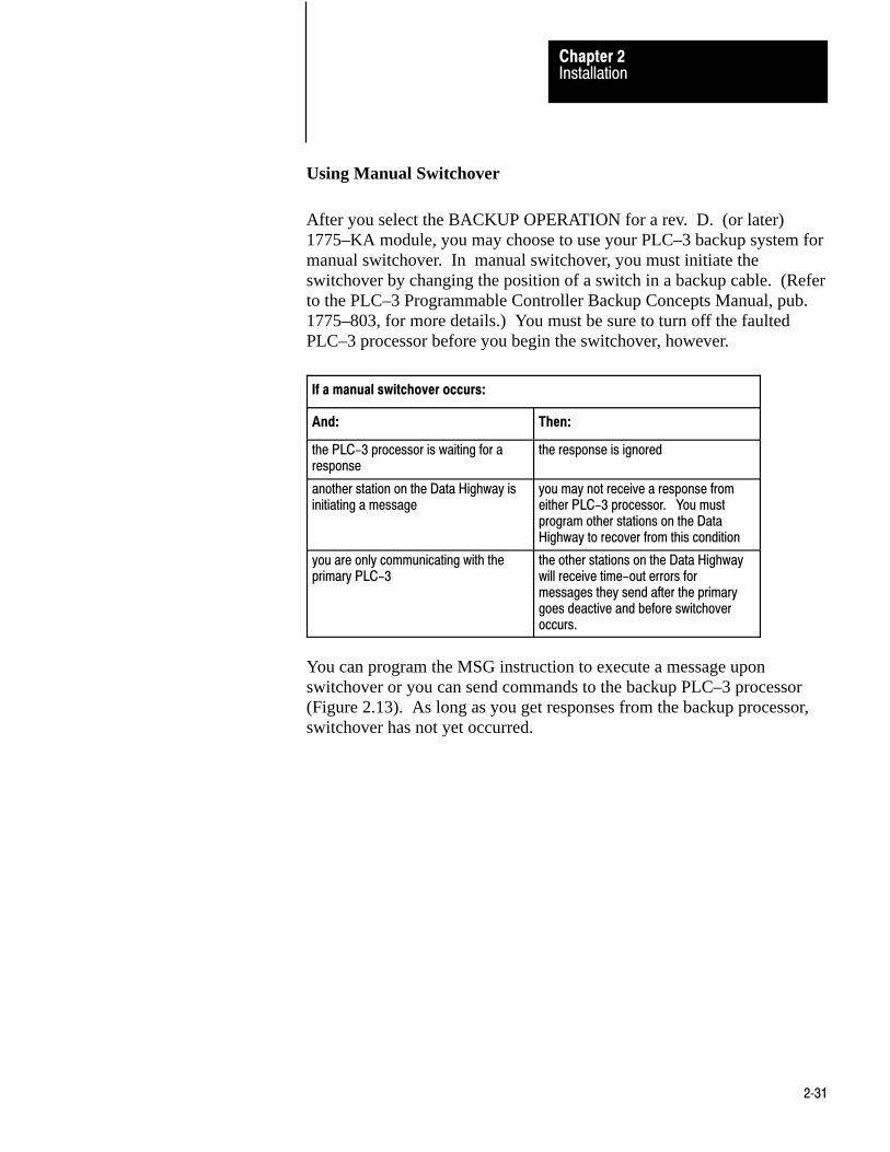
After you select the BACKUP OPERATION for a rev. D. (or later)1775–KA module, you may choose to use your PLC–3 backup system formanual switchover. In manual switchover, you must initiate theswitchover by changing the position of a switch in a backup cable. (Referto the PLC–3 Programmable Controller Backup Concepts Manual, pub.1775–803, for more details.) You must be sure to turn off the faultedPLC–3 processor before you begin the switchover, however.
If a manual switchover occurs:
And: Then:
the PLC-3 processor is waiting for aresponse
the response is ignored
another station on the Data Highway isinitiating a message
you may not receive a response fromeither PLC-3 processor. You mustprogram other stations on the DataHighway to recover from this condition
you are only communicating with theprimary PLC-3
the other stations on the Data Highwaywill receive time-out errors formessages they send after the primarygoes deactive and before switchoveroccurs.
You can program the MSG instruction to execute a message uponswitchover or you can send commands to the backup PLC–3 processor(Figure 2.13). As long as you get responses from the backup processor,switchover has not yet occurred.

InstallationChapter 2
2�32
Figure 2.13Example of a Rung that Sends a Message during switchover from primary PLC-3 to backupPLC-3.
EN
MSG
MESSAGE TYPE
CTL = FB200:00001 = 0
CHANNEL: E2.5.
#H045$N4:17= $B3:5 DN
ER
00
E0000
00
01
S0003
17
1
STAT
12
STAT
15
STAT
13
E0000 E0000
E0000
00 01
E0000L
17 01
E0000U
S0003
NOTE: Bits E0000/00 and E0000/01 are internal storage bits. You can use any unused datatable section to reference these bits. Bit S0003/17 is the run/backup bit.
Using Automatic Switchover
After you select the BACKUP OPERATION for a rev. D. (or later)1775–KA module, you may want to use automatic switchover for yourPLC–3 backup system. During automatic switchover:
the 1775–KA module for the primary PLC–3 processor disables itsData Highway port.
the 1775–KA module for the backup PLC–3 processor becomes theaddress that you selected with the LIST function (rather than thecorresponding address it received during the BACKUP OPERATION).
NOTE: You cannot select the BACKUP OPERATION for a multidropmodem applications because the modem port will not become disabledafter a PLC–3 processor fault regardless of the switch settings on themodule.

InstallationChapter 2
2�33
If an automatic switchover occurs:
And: Then:
the PLC-3 processor is waiting for aresponse
the response is ignored
another station on the Data Highway isinitiating a message
possibly neither of the PLC-3 processors willrespond to the message. You must programother stations on the Data Highway to recoverfrom this condition
another station is communicating withthe primary PCL-3 processor
the other station will receive no indication thata switchover has occurred. You can,however, program a MSG instruction toexecute a message upon switchover (fig.2.13) or send commands to the backupPLC-3 processor. If you are able tocommunicate with the backup, you know thatno switchover has occurred
Run/Backup Bit
It is important to alert the proper personnel when a switchover occurs.One way you can provide such indication is by having your programmonitor the run/backup bit (data table status section, file 0, word 3, bit 17)and turn on alarms or lights when the status changes from backup to run.This bit is set in the primary processor and reset in the backup processor.
It is also possible to link a single PLC–3 controller to more than one DataHighway by installing multiple 1775–KA modules in the same PLC–3. Inthis configuration, each 1775–KA module connects to a different DataHighway, and each has a unique station number on its associated highway.However, all the 1775–KA modules in the same PLC–3 controller canhave either the same or different station numbers.
CAUTION: If such a PLC–3 station is communicating througha PLC/PLC–2 buffer file and all of the stations’ 1775–KAmodules have the same station number, then all of thesemodules will transfer data through the same buffer file. Thiscan cause unpredictable results if several 1775–KA modules tryto read or write to the buffer file at the same time.
When such a PLC–3 station transmits a command message to a remoteData Highway station, the thumbwheel number specified in the PLC–3message instruction (section titled PLC–3 Stations) determines which1775–KA module actually transmits the command.
Multiple 1775-KA Modules inOne PLC-3

Chapter
3
3�1
Data Highway Communication
This chapter introduces some of the concepts and terminology involvedwith operating the 1775–KA module of the Data Highway.
The Allen Bradley Data Highway is a communication network forindustrial control applications. The Data Highway consists of a centraltrunkline cable that may be up to 10,000 feet long. This cable can linktogether as many as 64 distinct communication points (or nodes) calledstations.
Each station consists of some type of processor and a station interfacemodule. The station interface module enables the processor tocommunicate with other stations on the Data Highway. The 1775–KAmodule is the station interface module for the PLC–3 processor. Table 3.Alists all possible combinations of station interface modules and processors.
Table 3.AStation Components
Processor Station Interface Module
PLC-4 Microtrol 1773-KA Communication Interface Module
PLC-3 1775-KA Communication Adapter Module
PLC-2 Family 1771-KA Communication Adapter Module
PLC 1774-KA Communication Adapter Module
Computer or otherprogrammable
RS-232-C compatibledevice
1771-KC/KD/KE/KF Communication ControllerModule
Communication Terminology
Stations communicate with each other by sending messages over the DataHighway. There are two types of messages:
Command messages Reply messages
General
Some Terminology
Data Highway CommunicationChapter 3
3�2
A command message either gives (writes) data to, or requests (reads)data from, one station to another. A reply message is a station’s responseto a command message.
Command messages are generated by message procedures that youprogram into the 1775–KA module. Execution of a message procedure iscontrolled by the message (MSG) instruction in the PLC–3 ladderdiagram program. When a 1775–KA module receives a commandmessage from another station, the module automatically generates theappropriate reply message.
As points of reference, we can talk about local and remote stations. Thelocal station is the one currently initiating some action, or the one we arecurrently doing something with. All other stations are then remote.
We can also describe stations in terms of their relationship to a message.The transmitting station is the one sending the message, and thereceiving station is the one that gets the message. A station that transmitsa command message is called a command station, and a station thattransmits a reply message is called a reply station.
You can send either:
a single message procedure command (Chapter 6) that may be up to 76characters long.
the name of a Data Highway message procedure which contains agroup of commands and is stored in the 1775–KA module
You specify the station that will receive the command with a PLC–3extended address. This address always takes the form:
E2.5.nn
where
E2 specifies that this command addresses the module statusarea of PLC–3 memory
5 specifies that you are sending the message instructionthrough the 1775–KA module
nn is replaced with the thumbwheel setting on your particular1775–Ka module

Data Highway CommunicationChapter 3
3�3
To enter a message instruction, complete the steps below:
1. Enter a condition that, when true, will activate the messageinstruction. In Figure 3.1, we used an examine–on for input word00128, bit 01.
Figure 3.1Levels of Programming in Data Highway Communication
STATMSG
MESSAGE TYPE 1 STAT10012
01STAT
CTL = FB200:0000=200CHANNEL: E2.5.1
EN12
DN15
ER13
2) 1775–KA Module
@PROC_A
Data Highway Message ProcedurePROC_A
#H024$B12:37 = 15
Message procedure commandto transmit a message to datahighway station number 24
Message instruction toexecute message procedurePROC_A
1) PLC–3 Processor
Ladder Diagram Program
3) Data Highway
DLE STX DST SRC CMD STS TNSW ADDR SIZE DATA DLE EXT BCC(OPTIONAL)
Command messagetransmitted tostation 24
10014–I

Data Highway CommunicationChapter 3
3�4
2. Press the message instruction key.
3. Specify message type 1.
4. Choose a control file word where status information about themessage command can be stored. In our Figure 3.1, we used binaryfile 200, word 200.
Data transfers can be either solicited or unsolicited, depending on whetherthey are initiated by the local or a remote station, respectively. Either typeof station initiates the data transfer by issuing a command message. If thelocal station issues the command message, the corresponding replymessage is said to be solicited because the local station has solicited, orrequested, the data contained in the reply message. If a remote stationissues the command message, that message is said to be unsolicited.
For solicited messages, a local station receives data from a remote stationduring a read operation. The local station sends data to a remote stationduring a write operation.
For unsolicited messages, a local station receives data from a remotestation during a write operation. A local station sends data to a remotestation during a read operation.
In read operations, the command message requests the data transfer, butthe corresponding reply message actually contains the data beingtransferred. In write operations, the command message contains the databeing transferred, and the reply message merely reports the status (receiptor non–receipt) of the transfer.
The PLC–3 processor must be free to control its own processes at thesame time that the 1775–KA module is communicating over the DataHighway. For this reason, both the processor and the module have theirown programs and programming languages. Figure 3.1 illustrates howthese two programming levels (processor and module) interrelate.
PLC-3 Program
The first link in the communication process is your PLC–3 ladder diagramprogram. You send a Data Highway command message by means of themessage (MSG) instruction. Figure 3.1 shows a typical MSG instruction.
Levels of Programming
Data Highway CommunicationChapter 3
3�5
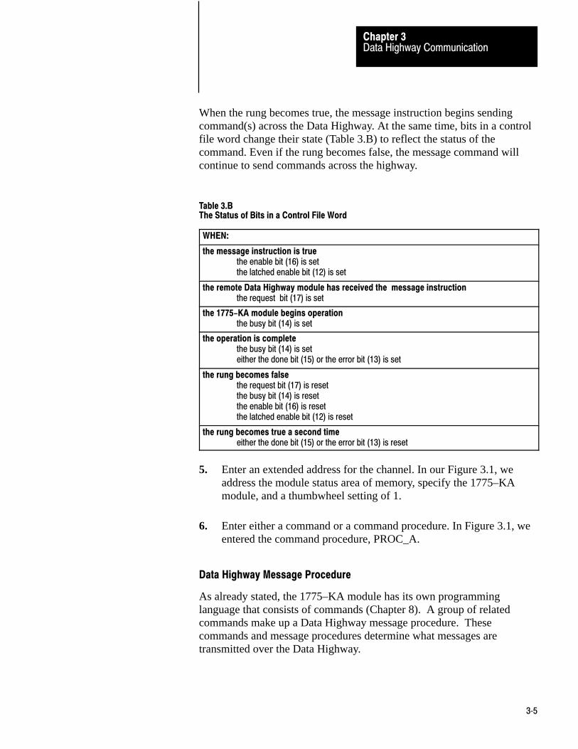
When the rung becomes true, the message instruction begins sendingcommand(s) across the Data Highway. At the same time, bits in a controlfile word change their state (Table 3.B) to reflect the status of thecommand. Even if the rung becomes false, the message command willcontinue to send commands across the highway.
Table 3.BThe Status of Bits in a Control File Word
WHEN:
the message instruction is truethe enable bit (16) is setthe latched enable bit (12) is set
the remote Data Highway module has received the message instructionthe request bit (17) is set
the 1775-KA module begins operationthe busy bit (14) is set
the operation is completethe busy bit (14) is seteither the done bit (15) or the error bit (13) is set
the rung becomes falsethe request bit (17) is resetthe busy bit (14) is resetthe enable bit (16) is resetthe latched enable bit (12) is reset
the rung becomes true a second timeeither the done bit (15) or the error bit (13) is reset
5. Enter an extended address for the channel. In our Figure 3.1, weaddress the module status area of memory, specify the 1775–KAmodule, and a thumbwheel setting of 1.
6. Enter either a command or a command procedure. In Figure 3.1, weentered the command procedure, PROC_A.
Data Highway Message Procedure
As already stated, the 1775–KA module has its own programminglanguage that consists of commands (Chapter 8). A group of relatedcommands make up a Data Highway message procedure. Thesecommands and message procedures determine what messages aretransmitted over the Data Highway.

Data Highway CommunicationChapter 3
3�6
The whole purpose of Data Highway communication is to transfer datafrom one station processor memory location to another. To accomplishthese data transfers, you can program the assignment command into the1775–KA module.
Chapter 6 gives the details of the assignment command. For now, let’s justlook at the simple example in Figure 3.2. In this example, the assignmentcommand copies a word (16 bits) of data from the source to thedestination location. The source of the data is always specified on theright of the equals sign (=), and the destination is always on the left.
Figure 3.2Example Assignment Command
$B45:21 = $I12:33
Source Address
Address Delimiter
Asignment Command
Destination Address
Address Delimiter
10015-I
Note that an assignment command does not destroy the data at the sourcelocation; rather, it just makes a copy of the source data at the destinationlocation. When the assignment is executed, both source and destinationwill contain the same data.
There are two ways to use a data transfer command with the 1775–KAmodule:
as a single command within a PLC–3 message instruction as one of multiple commands within a message procedure
Figure 3.3 illustrates both of these methods for the same assignmentcommand. Note that a message instruction in the PLC–3 ladder diagramprogram controls execution of the command in either case.
Data Transfers

Data Highway CommunicationChapter 3
3�7
Figure 3.3Two Ways to Use 1775-KA Commands
STATMSG
MESSAGE TYPE 1 STAT10012
01
STAT
CTL = FB200:0000=200CHANNEL: E2.5.1$B45:21=$112:33
EN12
DN15
ER13
STATMSG
MESSAGE TYPE 1 STAT10012
01STAT
CTL = BW200:0000=200CHANNEL: E2.5.01@ PROC_A
EN12
DN15
ER13
1) as a single commandin a PLC–3 message instruction
2) as part of a message procedure
Message Procedure PROC_A
(other commands)
$B45:21 = $112:33
(other commands)
PLC–3 Message Instruction to ControlExecution of Procedure PROC_A
10016–I

Data Highway CommunicationChapter 3
3�8
Access privileges
Not every Data Highway station can read or write to every other station.In general, read and write access privileges depend on two factors:
type of processor at the transmitting and receiving stations protections set at the receiving station
The rest of this section explains how these access privileges varyaccording to the above factors.
PLC–3 Stations
A PLC–3 station can always read data from any major area of anotherPLC–3’s memory. However, one PLC–3 station can write only to the datatable area of another PLC–3 station.
In addition, a local PLC–3 station can prevent remote PLC–3 stationsfrom writing to the local station’s data table by setting a memoryprotection switch. At the local station, the memory protect switch can beoverridden by selecting option 4 in the Module Options Menu (sectiontitled Accept Writes, chapter 2) at the local station.
PLC/PLC–2 Stations
For communication with a PLC or a PLC–2 station, read, and write accessprivileges depend on switch settings at that station. For an explanation ofhow to set the switches for read and write access, refer to theCommunication Adapter Module User’s Manual (publications 1771–6.5.1and 1774–6.5.8).
Accessing a PLC/PLC–2 Station
Access to a PLC/PLC–2 station also depends on the type of commandtransmitted to that station. There are two types of commands:
protected write commands unprotected read and write commands
Protected write commands can only write to specified sections of the datatable in a PLC/PLC–2 processor. Memory access rungs in the PLC/PLC–2ladder diagram program specify where in the data table the PLC–3 canwrite data.
Unprotected commands, on the other hand, can read or write to anysection of the data table at a PLC/PLC–2 station. (Again, refer topublication 1771–801 or 1774–819 for an explanation of protected andunprotected commands and memory access rungs.)

Data Highway CommunicationChapter 3
3�9
A PLC–3 station can read from any part of a PLC/PLC–2 data table.However, A PLC– 3 station cannot write to a PLC/PLC–2 if the switchsettings at the PLC/PLC–2 station forbid access. If the switches at thePLC/PLC–2 station are set to accept only protected write commands, thenthe ladder diagram program at the PLC/PLC–2 station must containmemory access rungs to define which areas of the PLC/PLC–2 station’sdata table are accessible. In such a case, a transmitting PLC–3 station canwrite to only those data table areas defined by the memory access rungs,and only by means of protected write commands. If the switches at thePLC/PLC–2 station are set to accept unprotected write commands, aPLC–3 station can then write to any area of the PLC/PLC–2’s data tableby transmitting an unprotected write command (section titled CommandMessage Type chapter 6).
Accessing a PLC–3 from a PLC/PLC–2 Processor
While a PLC–3 processor can address any area of a PLC/PLC–2 datatable, a PLC/PLC–2 reads an input file that is a part of the PLC–3 datatable. That file is the PLC–3 input file with a number that corresponds tothe station number of the PLC/PLC–2 station. For example, theread/write files assigned to PLC/PLC–2 stations 1 to 100 (octal) would beas follows:
PLC/PLC-2 StationNumber (octal)
Assigned PLC-3 Input Filefor Read/Write Access
000 I008[1]
001 I001
002 I002
003 I003
004 I004
005 I005
006 I006
007 I007
010 I010
011 I011
012 I012
. .
. .
. .
077 I077
100 I100
[1] Station address 000 is assigned to input file I008. Otherwise PLC-3 input files with an 8 or 9 in their address are not used for read/write access by a PLC-PLC-2 station (except I008 for station 0).
Data Highway CommunicationChapter 3
3�10
PLC/PLC–2 station numbers are octal, while PLC–3 input files havedecimal addresses. This means that PLC–3 input files with an 8 or 9 intheir address are not used for read/write access by a PLC/PLC–2 station.
The PLC/PLC–2 station can use either protected or unprotectedcommands to access its assigned PLC–3 file. Note, however, that thePLC/PLC–2 station cannot access its assigned file until that file is createdand allocated at the PLC–3. To create a PLC–3 file, use the CREATEcommand described in the PLC–3 Programming Manual (publication1775–801).
Note that it is possible to have two PLC–3 stations communicate witheach other as if they were PLC/PLC–2 stations. To do this, simply allocatethe appropriate PLC/PLC–2 buffer files in the PLC–3 stations and usesthe PLC/PLC–2 addressing format (section titled PLC/PLC–2 AddressSpecifications, chapter 4) in the assignment commands. Similarly, acomputer can sent PLC/PLC–2 commands to a PLC–3 station by usingthe appropriate message packet formats (Appendix A).
To allow as many as 4 remote stations to access the same PLC–3 inputfile:
1. Enable the PLC–2 MASK option in the LIST function. PLC–2MASK is option 6 on the Module Options menu.
2. Select station numbers 1008 apart. For example, you could usestations 010, 110, 210 and 310.
The stations will have access to the input file which matches the lowertwo digits of these station numbers (input file 10 in this example). Whenthe 1775– KA module receives a PLC–2 type command, it masks theupper octal digit in order to determine which input file to access. Socommands sent from stations 010, 110, 210, and 310 would all accessinput file 10.

Data Highway CommunicationChapter 3
3�11
PLC–4 Stations
To read or write to a PLC–4 station, you can send either protected orunprotected commands.
Switches 2 and 3 (on the second row of switches) at the 1773–KA modulespecify whether the PLC–4 station will accept unprotected and protectedcommands (respectively) through the Data Highway port of the 1773–KAmodule.
Switches 1 and 3 (on the third row of switches) at the 1773–Ka modulespecify whether the PLC–4 station will accept protected and unprotectedcommands (respectively) through the RS–232–C port of the 1773–KAmodule. In all cases, if the switch is set to the closed position, the modulewill accept that type of command.

Chapter
4
4�1
Addressing Rules and Examples
This chapter presents some general rules for specifying data addresses inmessage procedures. This chapter assumes that you are already familiarwith the forms and meanings of addresses in the PLC–3 and otherAllen–Bradley programmable controllers. For details on these subjects,refer to the appropriate documentation listed in Table 4.A.
Table 4.AMemory Organization Documentation
Controller Document PublicationNumber
(Old/New No.)
PLC-3 PLC-3 Programming Manual 1775-801/1775-6.4.1
PLC PLC Programming & Operations Manuals 1774-800/1774-6.8.1
PLC-2 PLC-2 Memory Organization and Structure 1772-907/---------
PLC-2/30 PLC-2/30 Memory Organization 1772-914/1772-4.4
PLC-2/20 Memory Organization of PLC-2.20 Controller 1772-909/1772-4.3
PLC-2/15 PLC-2/15 Memory Organization 1772-912/---------
PLC-4 PLC-4 Microtrol Product Guide 1773-800/1773-6.5.1
In this chapter,the addressing formats are presented in shorthand notation.The notation used is as follows:
<bit> - the number of a particular bit within theaddressed word
<fileaddr> - the logical address of a PLC–3 file
<filesym> - a symbolic address of a PLC–3 file
<offset> - the number of words between thebeginning of the file and the desired word(offset is zero for the first word of a file)
<size> - number of words of data to be transferred
<wordaddr> - the logical address of a PLC–3 word
<wordsym> - a symbolic address of a PLC–3 word
General

Addressing Rules and ExamplesChapter 4
4�2
An expression can be used in place of any of the above fields in anaddress.
Within the above listed fields of an address specification, numbers areinterpreted as decimal (base 10) unless you indicate that they are octal(base 8). You can specify an octal number by enclosing the number inparentheses and starting it with a leading zero. For example, 17 isinterpreted as decimal 17, but (017) is interpreted as octal 17, or decimal15.
An exception to the above rule occurs when addressing a word in theinput or output sections of PLC–3 memory. In these cases, the wordaddress <wordaddr> is normally interpreted as an octal number,regardless of leading zeros. To express an input or output word address asa decimal value, enclose the word address within parentheses andeliminate leading zeros.
In addressing individual bits, parentheses have no affect on the addressinterpretation The bit address <bit> is interpreted as an octal number if itstarts with a leading zero and as a decimal number if it does not start witha zero.
Figure 4.1 illustrates these addressing conventions.
Figure 4.1Examples of Addressing Conventions
Address Specification Interpretation (expressed in decimal)
I12:15 Input file 12, word 13
I12:15/15 Input file 12, word 13, bit 15
I12:015/015 Input file 12, word 13, bit 13
I12:(15) Input file 12, word 15
I12:(015) Input file 12, word 13
N43:15 Integer file 43, word 13
N043:15 Integer file 43, word 13
N(043):15 Integer file 35, word 13
N(43):15 Integer file 43, word 13 10017-I
Number Systems

Addressing Rules and ExamplesChapter 4
4�3
Data is referenced by its address in memory. In a message procedure, youmust precede an address with a dollar sign. The dollar sign acts as adelimiter to tell the 1775–KA module that it has encountered a dataaddress. Figure 4.2 illustrates this addressing format in a simpleassignment command.
Figure 4.2Example Assignment Command Showing Addressing Format
$B45:21 = $I12:33< <
Destination Source
Assignment Command
Address Address
10018-I
For data locations at remote stations, the remote station number mustprecede the data address. Figure 4.3 illustrates this addressing format.For communication on the Data Highway, the characters #H are requiredto delimit the remote station number. For RS–232–C communicationthrough the 1775–KA module’s modem port, the characters #M delimitthe remote station number.
Figure 4.3Example of Remote Station Addressing in an Assignment Command
$B45:21 = $I12:33
< <
#H024
<
Source AddressAddress DelimiterAssignment Command
Destination Address
Address Delimiter
Remote Station Number (octal)
Data Highway Port Identifier
Remote Station Delimiter
10019-I
Addresses
Addressing Rules and ExamplesChapter 4
4�4
You can also use symbols to represent data and data addresses in messageprocedures. A symbol can consist of numeric digits, alphabeticcharacters, and the underline character (_). No other special charactersare allowed. The first character in a symbol must be a letter of thealphabet.
Both upper–case and lower–case letters are acceptable in a symbol, butthey are distinguished. For example, ASYMBOL and Asymbol are twodifferent symbols.
A symbol can be any length, but it must be unique in its first 8 characters.For example, SYMBOL_A and SYMBOL_B are distinguishable in amessage procedure, but NEW_SYMBOL_A AND NEW_SYMBOL_Bare not. Note that indistinguishable symbols are not flagged asprogramming errors. Rather, indistinguishable symbols are treated asequivalents.
Certain words and character combinations cannot be used as symbolsbecause they are reserved for special uses in message procedures. Thereserved words are:
CREATE IF
DELETE ON_ERROR
ERROR PROT
EXIT STOP
GOTO UNPRO
Any abbreviated form of one of the above words is also invalid as asymbol. For example, the single letter C should not be used as a symbolbecause it is an abbreviation of the word CREATE. Similarly, PRO is aninvalid symbol.
Figure 4.4 illustrates the classification of different types of symbols. Thetwo major classifications are:
system symbols user symbols
Symbols

Addressing Rules and ExamplesChapter 4
4�5
Figure 4.4Symbol Types
User SymbolGenerate this symbolicvalue through theassignment command
Symbol
System SymbolGenerate this symbolwith the Edit command(for a procedure name)or a Create command(for a symbolic address).
ProceduralApplies only to theprocedure in which it isgenerated.
InterproceduralApplies to the procedurein which it is generatedplus any other procedurenested together with thatprocedure
Procedure NameApplies to a singleprocedure or otherprocedures nestedtogether within thatprocedure.
GlobalApplies to any context.
Symbolic AddressCan be used anywherein place of a logicaladdress.
LocalApplies only to thecontext in which thesymbol is generated.
10021–I
System Symbols
A system symbol is used as either a procedure name or a symbolicaddress. The characters in a system symbol must conform to the generalrules given above for all symbols. System symbols are delimited by thecharacter @, which distinguishes them from user symbols.
Procedure Names
A procedure name is a way of referring to a message procedure. Youassign a procedure name at the time you generate, or edit, the messageprocedure (Chapter 6).
One procedure can execute a second procedure simply by stating thename of that second procedure. This allows for nesting of procedures upto three levels deep.
Symbolic Addresses
Addressing Rules and ExamplesChapter 4
4�6
A symbolic address is another way of representing the logical address ofdata (section titled Addresses). You can generate a symbolic address byusing the CREATE command (Chapter 8). A symbolic address can beused anywhere that a logical address can be used in a message procedure.The symbolic address is stored in the system symbols area of the PLC–3memory.
Scope of System Symbols
System symbols can be either local or global in scope. A global systemsymbol is known in any context. A local system symbol is known only inthe context in operation at the time the symbol was generated. Context isexplained in the PLC–3 Programming Manual (publication 1775–801).
At the time you generate the system symbol, you can specify whether it isto be local or global. If you do not specify the scope of the systemsymbol, it is assumed to be local.
Note that the terms local and global symbols should not be confused withlocal and remote stations. Both local and global symbols having meaningonly at the station in which they were generated.
User Symbols
A user symbol represents a numeric value. You can generate a usersymbol and assign a value to it by means of the assignment command(Chapter 7).
User symbols are either procedural or interprocedural. Procedural usersymbols are known only to the procedure in which they are generated.Interprocedural user symbols are known to the procedure in which theyare generated and to any other procedure nested within that procedure.
User symbols can contain data that is up to 32 bits long. If the high–orderbits are insignificant (that is, if they can be truncated without changing thevalue of the data), then the contents of the user symbol can be stored in adata field that is less than 32 bits long. Attempting to put a data value intoa field that is too small for it will generate an error code of 189 (AppendixB).

Addressing Rules and ExamplesChapter 4
4�7
The PLC–3 processor uses logical addresses to reference data in memory.No PLC–3 address is valid unless it memory location has been allocated.You can allocate memory by using the CREATE command in PLC–3programming. The PLC–3 Programming Manual (publication 1775–6.4.1)explains how to do this. Note that the CREATE command for memoryallocation is different than the CREATE command for creating symbolicaddresses (Chapter 6).
The following rules apply when specifying a PLC–3 logical address in amessage procedure:
1. Symbolic addresses must be defined to either the word level or thefile level of specification.
2. A word address may be either: (a) a block address specified to theword level, (b) a symbolic address of a word, or (c) a symbolic fileaddress followed by a colon (:) and an offset.
3. A size specification must be preceded by a word address and acomma (,).
4. An offset specification must be preceded by a file address and acolon (:).
5. A bit number must be preceded by a word address and a slash (/).
6. To access the pointer or floating point sections of memory, extendedaddressing must be used.
These rules are applied in the formats given below for addressing PLC–3data locations.
Addressing a File
The format for addressing a PLC–3 file is one of the following:
<fileaddr><flesym>
For assignment commands that copy data from one file to another, boththe source and the destination file must be exactly the same size.
PLC-3 Address Specifications

Addressing Rules and ExamplesChapter 4
4�8
For PLC–3 timer and counter files, it is important to note that the datawords are stored in the following order:
CTL PRE ACC
That is, the control, preset, and accumulated values for a given timer orcounter are stored as consecutive words in the same file.
Addressing a Word Range
To address a range of words in PLC–3 memory, use one of the followingformats:
<wordaddr><size><filesym>:<offset>,<size><wordsym>,<size>
Figure 4.5 is an example of addressing a range of PLC–3 words.
Figure 4.5Example of Addressing a Range of PLC-3 Words
$N 15 : 0, 20
< <
Number of words to
Delimiter
Address of first word be transferredto be transferred.
10022-I
You may use a word range only as the source field in an assignmentcommand. The destination must be a file that is as large as, or larger than,the source range.
Addressing a Word
To address a single word in PLC–3 memory, use one of the followingformats:

Addressing Rules and ExamplesChapter 4
4�9
<wordaddr><filesym>:<offset><wordsym>
Note that <wordaddr>is interpreted as an octal value if the addressedword is in an input or output file. Otherwise, <wordaddr>is interpreted asa decimal value (section titled Number Systems).
To access words in the pointer of floating point sections of PLC–3memory, use the PLC–3 extended addressing format. You can read aboutextended addressing in:
PLC–3 Programmable Controller Programming Manual (pub. no.1775–6.4.1)
Addressing a Bit
To address a specific bit within a PLC–3 word, use one of the followingformats:
<wordaddr>/<bit><filesym>:<offset>/<bit><wordsym>/<bit>
Figure 4.6 gives some examples of addressing individual bits in PLC–3memory.

Addressing Rules and ExamplesChapter 4
4�10
Figure 4.6Example of Addressing Specific Bits in PLC-3 Memory
@FILE_A:16/8
<Bit number 8 (decimal)
Delimiter
Word offset from bewginning of file
Delimiter
Symbolic address of file
10023-I
$B1:5/012
<
Bit number 8 (decimal)
Delimiter
Logical word address
The PLC and PLC–2 processors use logical data addresses. Theseaddresses are usually specified as octal numbers. However, the 1775–KAmodule interprets these addresses as decimal numbers unless they containleading zeros (section titled Number Systems). Therefore, if you want tospecify a PLC or PLC–2 word address as an octal number, begin thenumber with a 0(zero).
Addressing a Word Range
To address a range of words in PLC or PLC–2 memory, use this format:
<offset>,<size>
Figure 4.7 illustrates this addressing format
You may use a word range only as the source field in an assignmentcommand.
PLC/PLC-2 AddressSpecifications
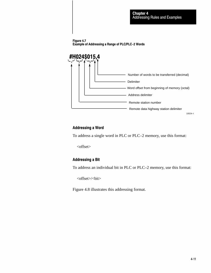
Addressing Rules and ExamplesChapter 4
4�11
Figure 4.7Example of Addressing a Range of PLC/PLC-2 Words
#H024$015,4
< < <
Number of words to be transferred (decimal)
Delimiter
Word offset from beginning of memory (octal)
Address delimiter
Remote data highway station delimiter10024–I
Remote station number
Addressing a Word
To address a single word in PLC or PLC–2 memory, use this format:
<offset>
Addressing a Bit
To address an individual bit in PLC or PLC–2 memory, use this format:
<offset>/<bit>
Figure 4.8 illustrates this addressing format.
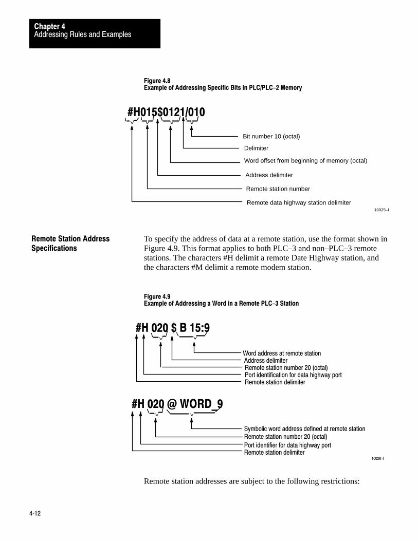
Addressing Rules and ExamplesChapter 4
4�12
Figure 4.8Example of Addressing Specific Bits in PLC/PLC-2 Memory
#H015$0121/010
< < <
Bit number 10 (octal)
Delimiter
Word offset from beginning of memory (octal)
Address delimiter
Remote station number<
Remote data highway station delimiter10025–I
To specify the address of data at a remote station, use the format shown inFigure 4.9. This format applies to both PLC–3 and non–PLC–3 remotestations. The characters #H delimit a remote Date Highway station, andthe characters #M delimit a remote modem station.
Figure 4.9Example of Addressing a Word in a Remote PLC-3 Station
#H 020 $ B 15:9
<<
Word address at remote stationAddress delimiterRemote station number 20 (octal)Port identification for data highway portRemote station delimiter
#H 020 @ WORD_9
<<
Symbolic word address defined at remote stationRemote station number 20 (octal)
Port identifier for data highway portRemote station delimiter
10026-I
Remote station addresses are subject to the following restrictions:
Remote Station AddressSpecifications
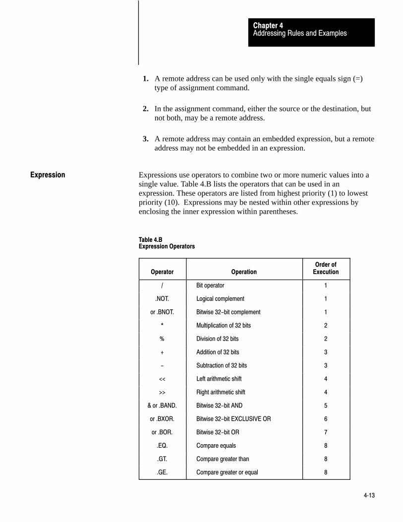
Addressing Rules and ExamplesChapter 4
4�13
1. A remote address can be used only with the single equals sign (=)type of assignment command.
2. In the assignment command, either the source or the destination, butnot both, may be a remote address.
3. A remote address may contain an embedded expression, but a remoteaddress may not be embedded in an expression.
Expressions use operators to combine two or more numeric values into asingle value. Table 4.B lists the operators that can be used in anexpression. These operators are listed from highest priority (1) to lowestpriority (10). Expressions may be nested within other expressions byenclosing the inner expression within parentheses.
Table 4.BExpression Operators
Operator OperationOrder of
Execution
/ Bit operator 1
.NOT. Logical complement 1
or .BNOT. Bitwise 32-bit complement 1
* Multiplication of 32 bits 2
% Division of 32 bits 2
+ Addition of 32 bits 3
- Subtraction of 32 bits 3
<< Left arithmetic shift 4
>> Right arithmetic shift 4
& or .BAND. Bitwise 32-bit AND 5
or .BXOR. Bitwise 32-bit EXCLUSIVE OR 6
or .BOR. Bitwise 32-bit OR 7
.EQ. Compare equals 8
.GT. Compare greater than 8
.GE. Compare greater or equal 8
Expression

Addressing Rules and ExamplesChapter 4
4�14
OperatorOrder of
ExecutionOperation
.LT. Compare less than 8
.LE. Compare less or equal 8
.NE. Compare not equal 8
.AND. Logical AND 9
.OR. Logical OR 10
The result of an expression depends on the order in which the operatorsare executed. The order of execution depends on the type of operator andon left– to–right placement within the expression. Table 4.B gives theorder of execution for the different operators. For example, the command
$B67:45 = 6+3*2
would store the value 12 in word 45 of binary file 67. This is becausemultiplication is performed before addition.
If an expression contains several operators with the same order ofexecution, those operators will be executed in the left–to–right order inwhich they appear within the expression. Extra set of parentheses can benested within each other to change the order of execution. In such cases,the expression within the inner–most set of parentheses is evaluated first.For example, the command
$B67:45=36%((6+3)*2)
would store the value 2 in word 45 of binary file 67 (% is the operator fordivision).
Expressions can be used anywhere that direct numeric values can be usedwithin a message procedure, including within an address field. Forexample, in the statement
$B67:(WORD+3)=5
the expression (WORD+3) specifies the address of a word within binaryfile 67. Note that the parentheses are necessary to indicate that +3 is partof the word address in this case.
Addressing Rules and ExamplesChapter 4
4�15
Number Systems
Within an expression, direct values are always interpreted as decimal(base 10) numbers unless you indicate that they are octal (base 8). Youcan specify an octal value by starting the number with a leading zero. Forexample, 17 in an expression is interpreted as decimal 17, but 017 isinterpreted as octal 17 (or decimal 15).
Operators
This section describes the operators listed in Table 4.B.
Bit Operator
The bit operator allows you to address a specific bit of a value storedunder a user symbol. For example, the statement
$I12:24/7=US_3/4
puts the value (0 or 1) of bit number 4 of user symbol US_3 into input file12, word 24, bit 7.
The bit address itself can also be a user symbol or an expression. Forexample, in the statement
$I12:24/7=US_3/(4+US_1)
the expression (4+US_1) specifies a particular bit within user symbolUS_3.
Note that the value appearing after the bit operator must be within therange of values allowed for bit addresses. Since user symbols are 32–bitvalues, a bit address for a user symbol must be in the range of 0 to 31(decimal). Bit addresses for data table words must fall in the range of 0 to15 (decimal).
Logical Operators
The logical operations are complement, AND, and OR. These operationsare used to construct logically true or false conditions. They are generallyused in decision statements such as the IF command (see section titled IFCommand, chapter 6).

Addressing Rules and ExamplesChapter 4
4�16
The result of a logical complement is 1 (true) if the expression followingthe .NOT. is a value of 0 (zero). Otherwise, the result is 0 (false). Forexample, consider the command
$I12:24=.NOT.SYMBOL_A
If the value of SYMBOL_A is 0 (zero), then a 1 is stored in word 24 ofinput file 12. If the value of SYMBOL_A IS anything other than 0, then a0 (zero) is stored in word 24 of input file 12.
The result of a logical AND is 1 (true) if the expression preceding the.AND. and the expression following the .AND. are both non–zero.Otherwise, the result is 0 (false).
The result of a logical OR is 1 (true) if either the expression preceding the.OR., the expression following the .OR., or both expressions arenon–zero. Otherwise, the result is 0 (false).
Bitwise 32–Bit Operators
Bitwise 32–bit operators manipulate the individual bits in a 32–bitoperand.
The bitwise 32–bit complement (.BNOT.) inverts the state of each bit inthe 32– bit expression. That is, bits set to 1 are inverted to 0, and bits setto 0 are inverted to 1.
The bitwise 32–bit AND (.BAND.) forms a bit–by–bit logical AND oftwo 32–bit operands. There is no carry from one bit position to the nextwithin the operand. For example, if
A contains the bit pattern10101010010011110010101010101011
B contains the bit pattern01110101011100100010101110001010
then the assignment C=A.BAND.B yields
C contains the bit pattern00100000010000100010101010001010

Addressing Rules and ExamplesChapter 4
4�17
The bitwise 32–bit EXCLUSIVE OR (.BXOR.) forms a bit–by–bit logicalEXCLUSIVE OR of two 32–bit operands. There is not carry from one bitposition to the next within the operand.
The bitwise 32–bit OR (.BOR.) forms the bit–by–bit logical OR of two32–bit operands. There is not carry from one bit position to the nextwithin the operand.
Arithmetic Operators
The arithmetic operations are addition, subtracting, multiplication, anddivision. These are binary (not BCD) operations that produce 32–bitsigned integer results.
A result from these arithmetic operations should normally be assigned to a32– bit destination. The result can be assigned to a 16–bit destination onlyif the result is small enough in absolute value (less than 65,535) to fit into16 bits. If the result is assigned to a 16–bit destination but is too large tofit into 16 bits, then an error code of 215 results.
There is no indication of overflow or underflow conditions witharithmetic operations.
Shift Operators
When a left arithmetic shift (<<) is executed, zeros are shifted into therightmost bits of the expression. The leftmost bit are shifted out of theexpression and are lost.
When a right arithmetic shift (>>) is executed, the leftmost bit of theexpression does not change. If the leftmost bits is a 1, then 1’s are shiftedin from the left. If the leftmost bit is a 0 (zero), then 0’s are shifted infrom the left. Since the leftmost bit of an expression is the sign bit, thismeans that the right arithmetic shift does not change the sign of a numericvalue. The rightmost bits are shifted out of the expression and are lost.
Comparison Operators
Comparison operators result in a value of 1 if the comparison is true and 0(zero) if the comparison is false. For example, consider the command
$I12:23 = ($CACC:1.GE.$CACC:2)
Addressing Rules and ExamplesChapter 4
4�18
If the accumulated value of counter 1 is greater than or equal to theaccumulated value of counter 2, then the number 1 is stored in word 23 ofinput file 12. If the accumulated value of counter is less than theaccumulated value of counter 2, a value of 0 (zero) is stored in word 23 ofinput file 12.
Resulting Values
The result of an expression is a 32–bit value. If the high–order bits arenot significant (that is, if they can be truncated without changing the valueof the expression), then the result can be stored in a data field that is lessthan 32 bits long. Attempting to put a value into a field that is too smallfor it results in an error code of 215 (Appendix B).

Chapter
5
5�1
Editing
This chapter explains how to create and edit message procedures andcommands for the 1775–KA module. The message procedure commandsthemselves are described in Chapter 6.
The general steps for editing a 1775–KA message procedure are:
1. Create and edit the PLC–3 ladder diagram program containingmessage instructions to control execution of the 1775–KA messageprocedure.
2. Allocate memory to the necessary PLC–3 data files.
3. Create and edit the 1775–KA message procedure.
You can perform the first two steps through an Industrial Terminal (cat.no. 1770–T4) connected to the I/O Scanner–Programmer InterfaceModule (cat. no. 1775–S4A). The third step can be performed eitherthrough an Industrial Terminal or through a data terminal connected to theI/O Scanner–Message Handling Module (cat. no. 1775–S4B). These stepsare described below.
Table 5.A gives an example of how to edit the message instruction in thePLC–3 ladder diagram program. For more details on this type of editing,refer to the PLC–3 Programming Manual (publication 1775–801).
General
Editing the Message Instruction

EditingChapter 5
5�2
Table 5.AExample of Message instruction Editing
System Prompt Action Key Strokes
Start edits. SED [ENT]
Insert rung. IR [ENT]
Enter the energize bit for the messagerung. In this case, binary file 0, word 0, bit0.
-] [- B0:0/0 [ENT]
Enter the message instruction. MSG [ENT]
ENTER FILE ADDRESS Enter the address of the file where themessage instruction will reside in memory.In this case, binary file 1.
FB1 [ENT]
ENTER SYSTEMADDRESS ORSYMBOL
Enter the channel designation for the1775-KA module. In this case, 2 is themodule status, 5 is the 1775-KA moduletype, and 1 is the thumbwheel number ofthe module.
E2.5.1 [ENT]
ENTER MESSAGETYPE
Enter the message type. This is always 1for the 1775-KA module.
1 [ENT]
Enter a single 1775-KA assignmentcommand or the name of a messageprocedure. In this case, the name of themessage procedure is PROC_1.
@PROC-1 [ENT]
End edits. EE [ENT]
Before the 1775–KA module can transfer data to or from any file inPLC–3 memory, that file must exist and it must have enough memoryallocated to it to accommodate the data transfer. You can create andallocate a file using the PLC–3 memory management commands. Refer tothe PLC–3 Programming Manual (publication 1775–801) for a descriptionof memory management.
Table 5.B shows an example of editing a message procedure through anIndustrial Terminal connected to a 1775–S4A module. Table 5.C showshow to edit the same message procedure through a data terminalconnected to a 1775–S4B module.
Allocating Memory
Editing Message Procedures

Chapter 5
5�3
Table 5.BExample of Editing a Message Procedure Through an Industrial Terminal
System Prompt Action Key Strokes
Create the message procedure. In thiscase, MH1 mean Data Highway messageprocedure number 1.
ME, MH1, [ENT]
Deleting existing null characters. [DEL] [DEL] [DEL] [DEL]
Enter message procedure commands.Note that you must use either an EXIT or aSTOP command to end each procedure.
(other commands)#H022$B0:5CC:1 [ENT]$B0:6=CC:1*2 [ENT]EXIT [ENT][CANCEL CMD]
Insert the symbol definition for the name ofthe message procedure.
IS [ENT]
ENTER SYMBOLSTRING
Enter the name of the message procedure.In this case, the name is PROC_1.
PROC_1 [ENT]
ENTER SYSTEMADDRESS ORSYMBOL
Enter the address where the messageprocedure is stored. In this case, thesymbolic address MH1 can be used.
MH1 [ENT]
ENTER SYMBOL TYPE Enter the symbol type for the messageprocedure name. This is always 2 for the1775-KA module.
2 [ENT]
Table 5.CExample of Editing a Message Procedure Through a Data Terminal
S4B> Enter the edit mode and create themessage procedure name. Note that the1775-S4B module automatically createsthe symbol definition for the messageprocedure name.
EDIT /H@PROC_1 [RET]
<EOB>**
Enter the insert mode of editing I [RET]
Enter the message procedure command.Note that you must use either EXIT orSTOP command to end each procedure.
(other commands)#H022$B0:5=CC:1 [RET]$B0:6=CC:1*2 [RET]EXIT [RET]
Exit from the insert mode of editing. [RET]
Exit from the editing mode of the1775-S4B module.
E [RET]
S4B>
EditingChapter 5
5�4
Note that it is not always necessary to create a message procedure. If youwant to execute just a single assignment command that is no more than 76characters long, then you can enter that command as part of the ladderdiagram message instruction (Table 5.A). If you want to execute morethan one 1775–KA command, or if a single assignment command is morethan 76 characters long, then you must create a message procedure tocontain those commands.
Also note that every message procedure must end with either an EXIT ora STOP command. The EXIT command is normally preferred because theSTOP command is a more extreme measure that results in error 179(Appendix B).

Chapter
6
6�1
Message Procedure Commands
The 1775–KA module has its own command language that you can use inprogramming message procedures. This chapter describes the availablecommands and gives some examples on how to use them. Table 6.Asummarizes the commands.
Table 6.AMessage Procedure Commands
Command Format and Explanation
=(assignment)
<destination>3=<source>
Assign a numeric value to a user symbol or copy data fromthe source to the destination
CREATE C@<system symbol><logical address>Create a symbolic address and equate it to a logical address.
DELETE D @<system symbol>Delete a symbolic address or an entire message procedurefrom PLC-3 memory.
(execute) @<system symbol>Execute the named message procedure.
EXIT ETerminate execution of the current message procedure.
GOTO G <label>Continue executing the current procedure from the pointspecified by the label.
IF I <expression><embedded command>Execute the embedded command only if the specifiedexpression is true.
ON_ERROR O <embedded command>3Execute the embedded command only if an error occurs afterthis statement in the procedure.
STOP STerminate execution of the message (MSG) instruction in thePLC-3 ladder diagram program.
Each command can be abbreviated to the letters shown in the formatcolumn of Table 6.A. In general, it is best to abbreviate a command to theshortest possible form. This not only makes the commands easier toprogram, but it also saves memory space and reduces execution time.
General

Message Procedure CommandsChapter 6
6�2
Blanks may be inserted anywhere to improve the readability of a messageprocedure. However, blanks should be kept to a minimum because theyuse memory space and slow execution of the message procedure.
The assignment command is the most fundamental yet versatile of all thecommands. Its primary purpose is to copy data from the source location tothe destination location. Table 6.B lists the various types of sources anddestinations. Any type of source in Table 6.B may be used with any typeof destination listed.
Table 6.BData Source and Destination Types
Source Destination
Direct Value
Procedural user symbol Procedural user symbol (except whensource is remote)
Interprocedural user symbol Interprocedural user symbol (exceptwhen source is remote)
Logical address Logical address
Local symbolic address Local symbolic address
Global symbolic address Global symbolic address
Expression
Of special interest is the case where a user symbol is the destination of theassignment. In such a case, if the user symbol was not previously definedin the message procedure, a new symbol is generated. If the symbol hasalready been defined, using it again as a destination causes its value to bechanged to the value given it by the latest assignment command.
Note that you can not transfer data from another station and place it into auser symbol defined at your local PLC–3.
Format
The equals sign (=) is the assignment command. As Table 6.A shows, thedestination for the assignment is on the left of the equal sign, and thesource or the numeric value is on the right. In all cases, the source value isassigned to (or copied to) the destination location. Thus, the assignmentis from right to left on the command line. For example, the statement
$I12:024–US_5
Assignment Command

Message Procedure CommandsChapter 6
6�3
copies the value of user symbol US_5 into word 24 (octal) of input file12.
Modifiers
Several modifiers may be added to the basic assignment command. Thesemodifiers affect three aspects of the assignment:
Scope of assignment Priority level of Data Highway message Type of command message transmitted
Scope of Assignment
A double equals sign (==) can also be used for the assignment command.The extra equals sign modifies the scope of an assignment involving auser symbol. If the destination of the assignment is a user symbol, thedouble equals sign defines the destination to be an interprocedural usersymbol. With the single equals sign, the destination becomes a proceduraluser symbol.
For example, the statement
US_2==6
defines US_2 to be an interprocedural user symbol and assigns to it thevalue 6.
Do not use the double equals sign (==) with anything other than a usersymbol as the destination.
Message Priority
Data Highway messages may be either one of the following prioritylevels:

Message Procedure CommandsChapter 6
6�4
Normal Priority
If you use the less–than sign (<) with the assignment command, thecommand will generate a priority Data Highway message. Without theless–than sign, the assignment command will generate a normal DataHighway message.
For example, the statement
#H027$I15:4<=$I12:24
transmits a priority message to Data Highway station 27 (octal).
The priority modifier can be used with either type of assignment (=or==).
Important: Stations with high priority messages are given priority overstations with normal priority messages throughout the command/replycycle. For this reason, a command should be given a high prioritydesignation only when special handling of specific data is required. Usingan excessive number of high priority commands defeats the purpose ofthis feature and could delay or inhibit the transmission of normal prioritymessages.
Command Message Type
Command messages are of two types:
protected unprotected
As explained in section titled Data Transfers, (chapter 3), protectedcommands can access only specified areas of data table memory at aPLC/PLC–2 station. You will need to send a protected write commandonly if a switch at the remote PLC/PLC–2 prohibits other stations fromsending unprotected write commands. Unprotected commands can accessany area of the data table.
By default, command messages generated by the assignment command inPLC–3 message procedures are of the protected type. To generate anunprotected command message, use a blank space and the modifier Uafter the assignment command.

Message Procedure CommandsChapter 6
6�5
For example, the command
#H027$0121=17407
would generate a protected write command to write the value 1740–7 intoword 121 of Data Highway station 27. The command
#H027$0121=17407 U
would generate an unprotected command to do the same thing.
You may disable the transmission of unprotected commands through LISToptions (section titled Module Options, chapter 2).
The CREATE command generates a symbolic address and assigns it to alogical address. Table 6.A illustrates the format of the CREATEcommand. To create a local symbolic address, use the CREATE commandby itself (the modifier/LOCAL is optional). To create a global symbolicaddress, use the modifier/GLOBAL after the CREATE command. Ineither case, the symbol has meaning only at the station where it wascreated.
The modifier/GLOBAL can be abbreviated to /G, and /LOCAL can beabbreviated to /L. For example, the statement
C/G @ TOTAL $E0.0.0.7
creates the global system symbol TOTAL to represent the logical addressE0.0.0.7.
Note that this CREATE command for generating symbolic addressesshould not be confused with the CREATE command for allocating filespace in PLC–3 programming (Chapter 4).
The DELETE command serves three main purposes:
Deleting message procedures from PLC–3 memory Deleting symbolic addresses Deleting interprocedural user symbols
CREATE Command
DELETE Command

Message Procedure CommandsChapter 6
6�6
Using the DELETE command on a procedure name not only deletes thename but also erases the named procedure from PLC–3 memory. UsingDELETE on a symbolic address or interprocedural user symbol merelydeletes the symbol, but the data stored under that symbol remains intact.
Table 6.A shows the general format of the DELETE command. To deletea symbol or a procedure from the current context, use the DELETEcommand by itself (the modifier /LOCAL is optional). To delete asymbol or a procedure from all contexts, use the modifier/GLOBAL afterthe DELETE command.
The modifier /GLOBAL can be abbreviated to /G, and /LOCAL can beabbreviated to /L. For example, the statement
D/G @ PARTS_PGM
deletes the procedure PARTS_PGM from all contexts in PLC–3 memory.
Note that the /LOCAL modifier can be used on global system symbols. Insuch cases, the procedure or the symbol is deleted from the currentcontext but can still be used in the other contexts.
To execute a message procedure, simply enter the delimiter @ followedby the procedure’s name. For example, the statement
@FIRST_PROC
causes execution of the procedure named FIRST_PROC.
Procedure names may be used anywhere that command can be used. Inthis way, one procedure can execute (call) another procedure. This allowsfor nesting of procedures. However, procedures may not be nested morethan 3 layers deep.
The EXIT command terminates execution of the current messageprocedure. If the current procedure was called (executed) by anotherprocedure, the EXIT command returns control to the calling procedure.Control returns to the line following the execute statement.
Execute
EXIT Command

Message Procedure CommandsChapter 6
6�7
The format of the EXIT command is simply the single letter
E
Without any modifiers or parameters.
Each main procedure and nested procedure must end with either an EXITcommand or a STOP command. The EXIT command is the preferredmeans of ending a procedure because the STOP command results in error179 (Appendix B).
The commands in a message procedure are normally executedsequentially. The GOTO command can change the order of execution.
Table 6.A illustrates the format of the GOTO command. Note that theparameter for a GOTO command is a label. Labels are signposts, or tags,that mark a location within the message procedure.
To generate a label, simply enter it on any one of the lines in a messageprocedure. The format for the label is
LABEL _A:
Nothing else may appear on the same line with the label. The label itselfmust conform to the same rules of construction as user symbols do. Thetrailing colon (:) is required when you first generate the label, but do notuse the colon any other time you refer to the label.
When a GOTO command is encountered, execution of the messageprocedure resumes with the first command after the label specified in theGOTO. Note that you cannot use the GOTO command to jump from oneprocedure to another, even if the procedures are nested.
The IF command makes logic decisions in the message procedure. Table6.A shows the format of the IF command. The first parameter of the IFcommand is an expression (Chapter 4). The entire expression must beenclosed in a set of parentheses. The expression may be made as complexas desired through the use of multiple operators and nested expression.
The second element in the IF command is an embedded command. If thevalue of the expression is true (1), the embedded command is executed. If
GOTO Command
IF Command

Message Procedure CommandsChapter 6
6�8
the value of the expression is false (0), the embedded command is notexecuted. The embedded command may be any of the availablecommands except another IF or an ON_ERROR.
Figure 6.1 demonstrates the combination of a label, a GOTO command,and an IF command to construct a simple loop that assigns the integers 0through 7 to successive words in binary file 50.
Figure 6.1Example of Looping
NUM = 0
LOOP: $B50:(NUM) = NUM NUM = (NUM +1) IF (NUM .LE. 7) GOTO LOOP
10027-I
The ON_ERROR command specifies what action should be taken if anerror is encountered during execution of the message procedure. TheON_ERROR command is not executed sequentially in the procedure; it isexecuted only when an error occurs.
Table 6.A illustrates the format of the ON_ERROR command. TheON_ERROR command contains an embedded command that is executedwhen an error occurs.
The ON_ERROR command applies to all other commands between itselfand the next ON_ERROR command. For example, consider the followingsequence:
ON_ERROR Command

Message Procedure CommandsChapter 6
6�9
command line 1command line 2ON_ERROR GOTO RECOVERcommand line 3command line 4ON_ERROR ERR_CODE = $B2:16command line 5
In this sequence, the first ON_ERROR command applies to commandlines 3 and 4, while the second ON_ERROR command applies tocommand line 5.
Some command lines might not have an ON_ERROR command thatapplies to them. If an error occurs in such a command line,the procedurewill stop executing.
Appendix B lists the error conditions.
The STOP command terminates execution of the MSG instruction in thePLC–3 ladder diagram program. This means that the STOP commandstops execution of the current procedure and all procedures nestedtogether with the current one.
The format of the STOP command is simply the single letter
S
without any modifiers or parameters.
The STOP command is a drastic means of terminating a messageprocedure, so it should be used only when no other action is possible. Thenormal means of terminating a procedure is the EXIT command (sectiontitled EXIT Command). When the STOP command is used, it results in anerror code of 179 (Appendix B).
In addition to containing commands and nested procedures, a messageprocedure can also contain functions. Functions can be used anywhereexpressions can be used.
STOP Command
Functions

Message Procedure CommandsChapter 6
6�10
There are two functions:
TO_BCD FROM_BCD
Figure 6.2 illustrates the format of these functions as they might appear inan assignment command.
Figure 6.2Examples of TO-BCD and FROM-BCD Functions
$D:12 = TO_BCD (27)COUNT = FROM_BCD ($D:12)
< < <
Function Parameter
Function
Assignment Command
Destination ofResulting Value
10028–I
The parameter of the function must be enclosed in parentheses. Theparameter may be any one of the following:
A direct numeric value (either decimal or octal) An expression A user symbol A logical address A symbolic address
TO_BCD Function
The TO_BCD function converts its parameter into a binary coded decimalvalue that is 32 bits long. For example, the TO_BCD function inFigure 6.2 stores the number 27 in binary–coded–decimal format in word12 of the decimal section of PLC–3 memory. After this function isexecuted, word 12 will contain the following bit pattern:
0000 0000 0010 0111
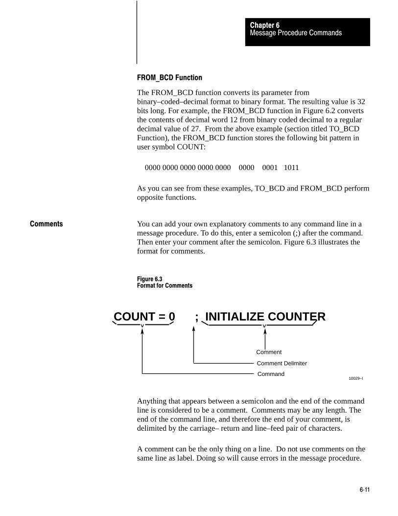
Message Procedure CommandsChapter 6
6�11
FROM_BCD Function
The FROM_BCD function converts its parameter frombinary–coded–decimal format to binary format. The resulting value is 32bits long. For example, the FROM_BCD function in Figure 6.2 convertsthe contents of decimal word 12 from binary coded decimal to a regulardecimal value of 27. From the above example (section titled TO_BCDFunction), the FROM_BCD function stores the following bit pattern inuser symbol COUNT:
0000 0000 0000 0000 0000 0000 0001 1011
As you can see from these examples, TO_BCD and FROM_BCD performopposite functions.
You can add your own explanatory comments to any command line in amessage procedure. To do this, enter a semicolon (;) after the command.Then enter your comment after the semicolon. Figure 6.3 illustrates theformat for comments.
Figure 6.3Format for Comments
COUNT = 0 ; INITIALIZE COUNTER
< <
Comment
Comment Delimiter
Command10029–I
Anything that appears between a semicolon and the end of the commandline is considered to be a comment. Comments may be any length. Theend of the command line, and therefore the end of your comment, isdelimited by the carriage– return and line–feed pair of characters.
A comment can be the only thing on a line. Do not use comments on thesame line as label. Doing so will cause errors in the message procedure.
Comments

Chapter
7
7�1
Error Reporting
The 1775–KA module detects and reports various types of errors.Appendix B lists all the errors reported by the module. As you can seefrom the appendix, some of the error codes relate to communications overthe Data Highway, while others relate to programming errors in themessage procedures.
The 1775–KA module reports errors by their code numbers. The modulestores the error code in the interprocedural user symbol ERROR. Thesymbol ERROR should be reserved exclusively for error reporting by themodule, so do not use this symbol for any other purpose.
ERROR contains only the last error encountered during execution of acommand or message procedure. If you want to save the error code ormanipulate it in any way, use an assignment command to copy the codeinto a more permanent storage word.
Unless you specify differently, the 1775–KA module will stop executingthe current message procedure as soon as the module detects an error. Tospecify a different action, use the ON_ERROR command in the messageprocedure. Then, when the module encounters an error, it will perform theaction specified in the nearest preceding ON_ERROR command. Afterthe module is done performing the ON_ERROR action, it will resumeexecuting the message procedure at the next command line after the onein which the error occurred.
For example, a message procedure can contain the command
ON_ERROR @ RECOVER
When an error occurs in the procedure, the above command will cause the1775–KA module to execute the procedure named RECOVER. Theprocedure RECOVER might be a routine for monitoring error codes.After executing RECOVER, the module will resume executing theoriginal procedure at the next command line following the one in whichthe error occurred.
General
Reporting Error Codes
Recovery from Errors
Error ReportingChapter 7
7�2
To aid in error monitoring, the 1775–KA module maintains a 6–worderror block in the module status area of PLC–3 memory. This error blockcontains the following information:
Word 0 – error code for the last error that occurred in the currentmessage procedure
Word 1 – total number of errors that occurred in the current messageprocedure
Word 2 – always contains the value 1
Word 3 – line number where the error occurred in the highest level(nest level 1) message procedure
Word 4 – line number where the error occurred in the next highest level(nest level 2) message procedure
Word 5 – line number where the error occurred in the lowest level (nestlevel 3) message procedure
The error codes reported are those listed in Appendix B.
The line number is the relative location of a command line from thebeginning of the message procedure containing the line. The first line ofeach procedure is line number 1, and any following lines are numbered inascending sequence. Nested procedures begin with line 1 again, thus theneed for words 3, 4, and 5 in the error block.
You do not enter the line numbers for a procedure; the 1775–KA moduleautomatically keeps track of the line numbers for you. The line numbersdo not appear in a listing of the message procedure, but they are recordedinternally by the module.
Error Block Operation
Figure 7.1 illustrates how the error block works. In this figure, anaddressing error (invalid destination address) occurs in procedure SUB2,which is nested 3 levels deep. Word 5 of the error block gives the linenumber where the error occurred in procedure SUB2. Word 4 gives thenumber of the line in procedure SUB1 that executed procedure SUB2.
Error Monitoring

Error ReportingChapter 7
7�3
And word 3 gives the number of the line in procedure MAIN thatexecuted procedure SUB1.
Figure 7.1Examples of Error Block Operation
MAIN
SUB 1
SUB 2
Line Number Procedure Word
150
28
5
Error Block
124
1
1
150
28
5
10030–I
0
1
2
3
4
5
@SUB 1
@SUB 2
6:12 = COUNT
•••
•••
•••
•••
•••
•••
Contents (decimal)
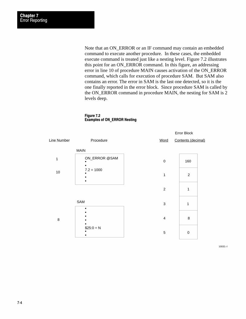
Error ReportingChapter 7
7�4
Note that an ON_ERROR or an IF command may contain an embeddedcommand to execute another procedure. In these cases, the embeddedexecute command is treated just like a nesting level. Figure 7.2 illustratesthis point for an ON_ERROR command. In this figure, an addressingerror in line 10 of procedure MAIN causes activation of the ON_ERRORcommand, which calls for execution of procedure SAM. But SAM alsocontains an error. The error in SAM is the last one detected, so it is theone finally reported in the error block. Since procedure SAM is called bythe ON_ERROR command in procedure MAIN, the nesting for SAM is 2levels deep.
Figure 7.2Examples of ON_ERROR Nesting
MAIN
SAM
Line Number Procedure Word
1
8
Error Block
160
2
1
1
8
0
10031–I
10
ON_ERROR @SAM
7.2 = 1000
0
1
2
3
4
5
Contents (decimal)
••
•••
•••••$25:0 = N••

Error ReportingChapter 7
7�5
Access to Error Block
The error block retains its data even after the message procedures aredone executing. It is re–initialized with each execution of a MSGinstruction in the PLC–3 ladder diagram program.
The extended address for the beginning of the error block file is
$E2.5.nn.4.0.
where “nn” is the thumbwheel number of the 1775–KA module. You canaccess this error block by any one of the following means:
Displaying it through the front panel of the PLC–3 controller Using the data monitor mode of the Industrial Terminal (cat. no.
1770–T4) Using the move status (MVS) command in the PLC–3 ladder diagram
program Using the I/O Scanner–Message Handling Module (cat. no. 1775–S4B) Using the 1775–KA module Using the 1775–GA

Chapter
8
8�1
Programming Examples
This chapter presents some detailed examples of 1775–KA modulecommands and message procedures.
The first set of examples shows individual commands that could beprogrammed directly into a PLC–3 message (MSG) instruction. Figure8.1 illustrates the differences in reading and writing data between twoPLC–3 stations. Figure 8.2 shows how to write different types of data to aremote PLC–3 station. Figure 8.3 shows how to write different types ofdata to a remote PLC or PLC–2 station.
Figure 8.1Reading and Writing PLC-3 Data Word
I0012
01EN
MSG
MESSAGE TYPE 1
CTL = FB200:0000=200
CHANNEL: E2.5.1
$NA:17=#H045 $B3:5
DN
ER
STAT
12
STAT
15STAT
13
Destination (local)
Source(remote)
Reading word 5 of binary file 3 at data highway station 045 into word 17 of integer file 4.
Writing word 5 of binary file 3 into word 17 of integer file 4 at data highway station 045.
I0012
02EN
MSG
MESSAGE TYPE 1
CTL = FB200:0001=200
CHANNEL: E2.5.1
#H045=N4:17 $B3:5
DN
ER
STAT
12
STAT
15STAT
13
Destination (local)Source
(remote) 10032-I
General
Individual Commands

Programming ExamplesChapter 8
8�2
Figure 8.2Writing Data to a Remote PLC-3 Station
10033-I
Data Type Assignment Statement
File #H045$N4 = $B3
Destination file must beexactly the same size assource file.
Word range #H045$N4:17 = $B3:5,20
Destination file must be largeenough to accept full rangebeing transferred.
20 words starting atword 5 of binary file 3
Word #H045$N4:17 = $B3:5
Bit #H045$N4:17/5 = $B3:5/13
Decimal bit numbers

Programming ExamplesChapter 8
8�3
Figure 8.3Writing Data to a Remote PLC/PLC-2 Station
10034-I
Data Type Assignment Statement
File #H021$040 = $B3
Destination PLC/PLC–2 file
Word range #H021$040 = $B3:5,20
Destination file must be largeenough to accept all wordsbeing transferred.
20 words starting atword 5 of binary file 3
Word #H021$040 = $B3:5/13
Bit #H021$040/5 = $B3:5/13
Decimal bit numbers
must be at least as large assource PLC–3 file.
Priority Write#H021$040 <= $B3:5
Priority assignmentcommand
Unprotected Write –– (refer to publication 1771–802 or 1774–6.5.8.)
affected by switch settings at remote PLC/PLC–2 station
#H021$040 = $B3:5 U Unprotected command
Space required

Programming ExamplesChapter 8
8�4
Figure 8.4 presents a printed listing of a Data Highway messageprocedure. As the listing indicates, the purpose of the procedure is tomonitor the state of a status bit in a remote Data Highway station.
Figure 8.4Example Data Highway Message Procedure
; PROCEDURE –– @REM_TURNON; This procedure will monitor the state of a bit in a remote; station and, when that bit goes true, turn on a bit; locally for either 300 seconds or until the remote bit; goes false.;
ON_ERROR @LOG_ERRORA = = 0 ;log errors and time of dayCREATE @TIM–START $B0:0CREATE @TIM_CTL $TCTL:1CREATE @TIM_PRE $TPRE:1T_ON_BIT = 0T_DONE_BIT = 017CREATE @PROCESS $N3:7P_ON_BIT = 5ON = 1OFF = 0LOOP 1: B0:0/1 = $H023$B5:3/2 IF ($B0:0/1 .EQ. OF) GOTO LOOP1@TIM_PRE = 300@TIM_START/T_ON_BIT = ON@PROCESS/P_ON_BIT = ONLOOP 2: $B0:0/1 = $H023$B:3/2 IF (($B0:0/1 .EQ. ON) .AND. (@TIM_CTL/T_DONE_BIT .EQ. OFF)) GOTO LOOP2@PROCESS/P_ON_BIT = OFFEXIT
;initialize error pointer;timer start word;timer control word;timer preset word;timer on bit;timer done bit;process word;process on bit
;check remote bit in loop;fetch and save remote bit
;set timer for 300 sec;turn timer on;turn process on;check timer and remote bit in loop;fetch and save remote bit
; PROCEDURE –– @LOG_ERROR
;This procedure will fetch the error block out of the; Module Status Area and record it along with the time; of day in status file 5.; CREATE @STATUS $S5 CREATE @ERR_BLK $E2.5.1.4.0 CREATE @TOD $S1:3 @STATUS: (A) = @ERR_BLK,6 @STATUS: (A + 6) = @TOD,2 IF ((ERROR .GE. 81) .AND. (ERROR .LE. 92)) GOTO NO_STN :no station – fatal error IF (A .GE. 72) GOTO TIMEOUT A = = A + 8 EXIT
;copy error block (6 words);copy time of day (hrs, mins)
;after ten errors, tell operator
; NO_STN: $S4:3/5 = 1 STOP
; TIMEOUT: $54:3/4 = 1 EXIT
;energize 1775–S4B report generation rung;exit procedure with an error
;energize 1775–S4B report generation rung;return to @PREM_TURNON
10035-I
Message Procedure

Programming ExamplesChapter 8
8�5
Some of the statements in the sample procedure are not necessary toaccomplish the bit monitoring. However, they were included to illustratemore of the functions and programming techniques available with the1775–KA module.
Note that the 300 second timer used in this example is not an accurate,real– time clock. This is because the time between successive executionsof the bit/timer check depends on Data Highway activity and on theactivity of the local PLC–3 processor. For example, if the 300 secondtimer times out immediately after its done bit is checked, the 1775–KAmodule will not detect this condition until its next pass through LOOP2.If the Data Highway is busy with other activity, it will take a while forLOOP2 to check the remote bit. PLC–3 ladder diagram programmingprovides better timer updates and responses.
The example procedure also assumes that the referenced memory areashave been created. Specifically:
1. Status file S5 must be big enough to hold a reasonable number oftimeout errors (error #37).
2. Timer T1 is a one–second timebase timer. Bit B0:0/0 controls theladder diagram rung that activates the timer. Figure 8.4 refers to thisbit as TIM_START/T_ON–BIT.
3. Bit S4:3/4 activates a message instruction that executes a reportgeneration procedure. In this way, the 1775–KA module canindirectly cause execution of a report generation procedure to displaya message on the operator’s terminal.
Chapter
9
9�1
Computer to PC Communication
This chapter and the chapters that follow (10,11, and 12) described how towrite a software driver that enables your computer to communicatethrough the RS–232–C port of the PLC–3 Communication AdapterModule. Therefore, you do not need to read these chapters if you are onlyusing PC’s. The interface modules contain software drivers for PC to PCcommunication.
In this chapter and the chapters that follow (10,11, and 12) we describe alayered approach to writing a software driver for your computer.According to the standard for network architecture developed by theInternational Standards Organization (ISO), communication networksshould be divided into layers. Each layer performs specific functions. Byseparating the communication network into independent layers, it is easierto make changes to one of the network’s functions without having toredesign the entire network. Ideally, the layers of a network should be asindependent of one another and interact with one another in the same wayas the organs of the human body. Because the organs of the human bodyare independent of one another, it’s possible for a surgeon to operate onthe lungs or heart without losing the life of the patient. Yet at the sametime the organs of the body interact when we run or walk or type on aword processor.
You should use a layered approach to developing communication softwarefor your computer. You don’t have to design your communicationsoftware in this layered fashion, but your software must perform all thefunctions described for the layers in this manual. In most cases, it will beeasier for you to implement and debug the communication software if youfollow this layered approach.
The Data Highway uses these four layers of the ISO model forcommunication between stations:
application layer – provides the Data Highway commands that you useto transfer data and manage the network.
network layer – determines how you address a Data Highwaycommand. It also provides less visible functions, such as controllingthe flow of information, establishing a path between stations, androuting messages from your station to another station.
Introduction to LayeredCommunication

Computer to PC CommuniationChapter 9
9�2
data link – checks the path between stations for errors to ensure thatdata is transmitted in a proper sequence, frames messages sent by astation and checks the integrity of messages received by a station. Thislayer is not visible to the person placing Data Highway commands in aprogram.
physical link – sets up, maintains, and disconnects a physical linkbetween two stations. This layer consists largely of hardware (DataHighway modules and cable). Like the data link layer, this layer is notvisible to the person placing Data Highway commands in a program.
A Data Highway command consists of many fields, each of whichoriginates from one of the above layers at the sending station. When astation receives a Data Highway command, it separates these fields so thata single layer uses only those fields it needs to perform its specificfunction.
The application layer uses these fields of a Data Highway command:
a command (CMD) field and function (FNC) field identify the type ofcommand that is sent.
a status field (STS) contains a code that indicates if the command wassuccessfully sent from one station to another.
an address (ADDR) field specifies the address in the remote station’smemory
a data (DATA) field contains the data that is sent from one station to theother.
These bytes and fields are discussed in greater detail later. For now, notice(Figure 9.1) that the FNC, ADDR, and DATA fields from the applicationlayer are treated as data by the network layer. We say that the data isframed by the fields of the network layer.

Computer to PC CommunicationChapter 9
9�3
Figure 9.1The Application and Network Layers
CMD STS FNC ADDR DATA
DST SRC CMD STS TNSData
(From Application Layer)
FromApplicationLayer
1006–I
x
0 x
NetworkLayerPacket
Legend: x = low hex digit of CMD byte supplied by application layer
The network layer uses these fields of a Data Highway command:
the destination (DST) and source (SRC) byte specify the address of thestation that is receiving the command and the address of the station thatis sending the command.
a command (CMD) byte at the network layer indicates whether themessage is a command or reply.
a status (STS) byte at the network layer indicates whether the messagewas successfully executed by the sending station.
a transaction (TNS) field identifies the particular command and replycycle the message belongs to.
Again, these bytes and fields are described in much greater detail later inthis manual. Notice (Figure 9.2) that the network layer (DST, CMD, STS,TNS,and the application layer) is treated as data by the data link layer.We say that this data is framed by the data link layer.
The data link layer uses these fields of a Data Highway command:
start of text (STX) end of text (ETX) enquiry (ENQ) acknowledge (ACK) data link escape (DLE) negative acknowledge (NAK) start of header (SOH) end of transmission (EOT) block check character (BCC)
These control characters are described in greater detail later in thismanual. The type of protocol you choose for the data link layerdetermines the meaning of these control characters.

Computer to PC CommuniationChapter 9
9�4
Figure 9.2The Application, Network and Data Link Layer of RS-232-C Communication (Full orHalf-Duplex)
CMD STS FNC ADDR DATA
DST SRC CMD STS TNSData
(From Application Layer)
DLE STXData
(From Network Layer) DLE ETX BCC
Full Duplex Link Packet and Half–Duplex Slave Packet
FromApplicationLayer
FromNetworkLayer
FromApplicationLayer
FromNetworkLayer
CMD STS FNC ADDR DATA
DST SRC CMD STS TNSData
(From Application Layer)
DLE SOH STN DLE STXData
(From Network Layer) DLE ETX BCC
Half–Duplex Master Message Link Packet10037–I
Data LinkLayer Packet
Data LinkLayer Packet

Computer to PC CommunicationChapter 9
9�5
We use the term protocol to describe the relationship between two similarlayers at two different stations. The protocol could, for example, be therelationship between the data link layer at station A and the data link layerat station B.
When you write a software driver for your computer, you may implementeither a data link layer that uses a half–duplex protocol or a data link layerthat uses a full duplex protocol. You select the half–duplex or full–duplexprotocol with the LIST function (section titled Modem Port, chapter 2).
In general, the full–duplex protocol provides higher data throughput, butyou can use it only for communication between two peer stations.
Half–duplex protocol is for one master and one or more slaves.Half–duplex protocol provides lower data throughput but is easier toimplement than the full–duplex protocol. You should use half–duplexprotocol if:
You are using multidrop baseband MODEMS to connect multiple slavestations to a single master computer. (You must use MODEMS for thistype of link unless there is only one slave).
You are using MODEMS that have only half–duplex capability You are willing to sacrifice data throughput in exchange for ease of
implementation
Half–duplex protocol does not allow embedded responses. The 1775–KAmodule has slave mode capability only; you must provide the masterfunction from your computer.
Full-Duplex vs Half-DuplexProtocol for the Data Link Layer
Chapter
10
10�1
Full-Duplex Protocol
If you are connecting the 1775–KA module to another Allen–Bradleycommunication interface module (such as a 1771–KG, 1775–KA,1773–KA, or 1771–KE/KF module), then you need not be concerned withthe protocol described here because the modules automatically take careof it. However, if you are connecting the 1775–KA module to acomputer, then you must program the computer to understand and to issuethe full–duplex protocol described in this chapter or the half– duplexprotocol described in chapter10. Specifically, this chapter outlines thelogic for a full–duplex, input/output driver (transmitters and receivers)used on the RS–232–C link.
A physical link consists of a cable and associated hardware, such astransmitter and receiver circuits. Protocol is the set of programming rulesfor interpreting the signal transmitted over the physical link by thehardware devices.
You can connect the 1775–KA module to either of two types of links:
Point–to–point physical link Multidrop physical link
You can select the 1775–KA module to provide either:
a full–duplex, unpolled protocol for peer–to–peer communication only a half–duplex, polled protocol for peer–to–peer or master/slave
communication
The type of communication protocol you can use depends on the type ofphysical link you have:
For this type of physical ink You can use this communication protocol
a point-to-point link either a peer-to-peer or master/slave communication
a multi-drop broadband MODEM link either a peer-to-peer or master/slave communication
a multi-drop baseband a master/slave communication MODEM link (becausethe link can support only one channel)
General
Definition of Link and Protocol

Full-Duplex ProtocolChapter 10
10�2
In general, full–duplex protocol gives higher data throughput, but it canhandle communication between only two peer stations. Half–duplexprotocol provides master–slave polling capability and can handlecommunication with as many as 255 slave stations, but it gives lower datathroughput.
This chapter describes the data link layer for full–duplex protocol.Chapter10 describes the data link layer for half–duplex protocol. Chapter12 describes the network layer and the application layer for bothprotocols.
The full–duplex protocol resembles ANSI X3.28–1976 specification,combining features of subcategories D1 (data transparency) and F1(two–way simultaneous transmission with embedded responses).
You can use full–duplex protocol for a point–to–point link or a multidropbroadband MODEM link that allows two–way simultaneous transmission. It is more difficult to implement than half–duplex because it requires youto use interrupts and multi–tasking programming techniques. It isintended for high– performance applications where you need to get thehighest possible throughput from the available communication medium.
At the 1775–KA module, select the unpolled mode with the LIST function(chapter 2).
Transmission Codes
Full–duplex protocol is a character oriented protocol that uses the ASCIIcontrol characters extended to eight bits by adding a zero for bit 7. SeeANSI X3.4, CCITT V.3, or ISO 646 for the standard definition of thesecharacters.
The particular ASCII control characters used are listed below.
Control Character Hexadecimal Code
STX (Start of Text) 02
ETX (End of Text) 03
ENQ (Enquiry) 05
ACK (Acknowledge) 06
DLE (Data Link Escape) 10
Full-Duplex Protocol

Full-Duplex ProtocolChapter 10
10�3
Additionally, a block check character (BCC) is used at the end of eachpacket for error checking. These bytes can be any value from 00 to FFhex.
In the following paragraphs we use the term code to mean an indivisiblesequence of ASCII characters or values having specific meaning to theprotocol. Indivisible means that the component bytes of a code must besent one after another with no other bytes between them. It does not referto the timing of the bytes.
Full–duplex protocol uses these codes:
Control codes:
DLE STX DLE ETX BCC DLE ACK DLE NAK DLE ENQ
Link–layer data codes:
Data (single bytes having values 00–0F and10–FF hex) DLE DLE (to represent the value 10 hex)
We can also group codes into two classes according to their use:
1. Message codes issued from a station sending a message.
2. Response codes issued from a station receiving a message.
The full–duplex codes sent by the station transmitting a message are:
DLE STX – indicates the start of a message packet. Link–layer data (00–OF and10–FF hex) – encodes the bytes of the
network packet. DLE DLE – encodes the value 10 hex in the network packet. This is
necessary to distinguish a text code of 10 hex from a DLE control codeof 10 hex.
DLE ETX BCC – terminates a message packet. DLE ENQ – requests the retransmission of the last received
transmission.
The full–duplex response codes sent by a station receiving a message are:

Full-Duplex ProtocolChapter 10
10�4
DLE ACK – signals that the receiver has successfully received the lastmessage sent.
DLE NAK – signals that the receiver did not successfully receive thelast message sent.
Link-Layer Message Packets
A link–layer message packet starts with a DLE STX, ends with a DLEETX BCC, and includes all link–layer data codes in between. Data codescan occur only inside a message packet.
Response codes occur inside a message packet. If you select theembedded responses option with LIST (chapter 2) the response codes canalso occur between a DLE STX and a DLE ETX BCC, but these responsecodes are not part of the message packet: they are referred to as embeddedresponses.
Figure 10.1 shows the format of a link–layer message packet forfull–duplex protocol, and the layer at which each portion should beimplemented. At the end of each message packet is the one–byte BCCfield.
Figure 10.1Link Packet Format for Full-Duplex Protocol
10038-I
CMD STS FNC ADDR DATA
DLE STXData
DLE ETX BCC(From Network Layer)
DST SRC CMD STS TNSData
(From Application Layer)
–––––––––––––
–––––––––––––
––––––––––
FromApplicaionLayer
FromNetworkLayer

Full-Duplex ProtocolChapter 10
10�5
Block Check
The block check character (BCC) is a means of checking the accuracy ofeach message packet transmission. It is the 2’s complement of the 8–bitsum (modulo–256 arithmetic sum) of all data bytes between the DLESTX and the DLE ETX BCC. It does not include any other messagepacket codes or response codes.
For example,if message packet contained the data codes 8, 9, 6, 0, 2, 4,and 3, the message packet codes would be (in hex):
10 02 08 09 06 00 02 04 03 10 03 EO
DLE STX Data DLE ETX BCC
The sum of the data bytes in this message packet is 20 hex. The BCC is the 2'scomplement of this sum, or EO hex. This is shown in the following binarycalculation:
0010 0000 20 hex11011011 1s compliment +11110 0000 2s compliment (E0 hex)
To transmit the data value 10 hex, you must use the data code DLE DLE.However, only one of these DLE data bytes is included in the BCC sum.For example, to transmit the values 8, 9, 6, 0, 10, 4, and 3 hex, you woulduse the following message codes:
Represents single data byte value of 10
10 02 08 09 06 00 10 10 04 03 10 03 D2
DLE STX Data DLE ETX BCC
In this case, the sum of the data bytes is 2E hex because only one DLEtext code is included in the BCC. So the BCC is D2 hex.

Full-Duplex ProtocolChapter 10
10�6
The BCC algorithm provides a medium level of data security. It cannotdetect transposition of bytes during transmission of a packet. It alsocannot detect the insertion or deletion of data values of zero within apacket.
Two-Way Simultaneous Operation
On a two–way simultaneous link, two physical circuits connect fourdistinct and independent software routines. Figure 10.2 shows thesesoftware routines as transmitters (XMTR) A and B and receivers (RCVR)A and B.
Figure 10.2Data Paths for Two-Way Simultaneous Operation
Transmitter
Receiver
B
B
A
A
Receiver
Transmitter
Path 1
Path 2
Path 3
Path 410039-I
There are also four independent data paths involved. Paths 1 and 3 carrymessage codes between A and B; paths 2 and 4 carry response codesbetween A and B.
A software multiplexer combines those message codes and response codesgoing in the same direction. At the other end of the link, a softwareseparator separates those message codes from the response codes.Internal software directs the message codes to the receiver and theresponse codes to the transmitter. On each physical circuit, you canintermingle response codes from a receiver to a transmitter with messagecodes sent from a transmitter to a receiver (unless you do not choose theembedded response option in LIST). Figure 10.3 shows thisimplementation.

Full-Duplex ProtocolChapter 10
10�7
Figure 10.3Software Implementation of Data Paths
TransmitterB
A
Receiver
Path 1Path 2
Transmitter
BAReceiver
M
S
S
M
Path 3 Path 4
Path 1Path 2
Path 3 Path 4
Physical Circuit AB
Physical Circuit BA
M
S
= Software Multiplexer
= Software Separator10040-I
Figure 10.4 shows path 1 with unrelated parts of Figure 10.3 removed.
Figure 10.4Data Path 1
TransmitterB
A
Receiver
M S
Path 1 Path 1
10041-I

Full-Duplex ProtocolChapter 10
10�8
We could show paths 2, 3, and 4 in a similar way.
The full–duplex protocol is symmetrical; that is, anything that we can sayabout transmitter A, receiver B, and paths 1 and 2 applies equally totransmitter B, receiver A, and paths 3 and 4. There are actually twoindependent instances of the protocol operating simultaneously. Forsimplicity, we define the link protocol on the subsystem that carriesmessages from A to B, with reference to figure 10.5
Figure 10.5Message Transmission from A to B
TransmitterB
A
Receiver
Path 1Path 2
M
S
S
M
Path 1Path 2
Path 1
Path 2
10042-I
Although the protocols on each subsystem operate independently, there isa slight delay when you transmit a response code in the middle of a streamof message codes. Also, any non–transient hardware problem that affectsmessage codes traveling over a hardware circuit affects response codes onthe same circuit.
Message Characteristics
In the network layer (chapter 12) the message source provides thetransmitter with the messages it sends. The message sink tells thereceiver what to do with the messages it receives.
Upon request from the transmitter, the message source supplies onenetwork packet at a time. It must be notified about the success or failureof the transfer to the receiver before supplying the next message. Whenthe message source is empty, the transmitter waits in an inactive state untila message is available.

Full-Duplex ProtocolChapter 10
10�9
Whenever the receiver has received a link packet successfully, it attemptsto give the network packet portion (link level data) to the message sink. Ifthe message sink is full, it must notify the receiver.
Figure 10.6 represents the protocol environment.
Figure 10.6Protocol Environment
Software Software
Hardware
SOURCE
NetworkPacket
NetworkPacketPath 1
Path 2Status Full
Transmitter
A
Receiver
BSINK
10043-I
Full–duplex protocol places the following restrictions on the networkpacket that is submitted to the link layer for transfer:
The size of a valid network packet is 6 bytes minimum, and 250 bytesmaximum.
The first byte of a network packet must be the station number of thereceiver station. The receiver ignores messages that do not contain thecorrect station number.
As part of the duplicate message detection algorithm, the receiverchecks the second, third, fifth, and sixth bytes of each network packet.(Recall that a network packet consists of the source, command, andtransaction fields.) At least one of these bytes of the current networkpacket must differ from the corresponding byte of the previous networkpacket in order for the receiver to accept the current network packet.Otherwise, the receiver assumes that the current packet is aretransmission of the previous packet, so it discards the current packet.
Transmitter Actions
Whenever the message source can supply a packet and the transmitter isnot busy, transmitter A sends a link packet on path 1. It then starts a
Full-Duplex ProtocolChapter 10
10�10
timeout, and waits for a response on path 2. You can use the diagnosticset timeout command to set this timeout period for the 1775–KA module.The default setting is 3 seconds.
When transmitter A gets a DLE ACK, the message transfer is complete.After signaling the message source that the message has been sentsuccessfully, transmitter A proceeds with the next message.
If transmitter A gets a DLE NAK, it retransmits the same message. Thetransmitter restarts the timeout and waits again for a response. By usingthe diagnostic set NAKs command, you can specify how many times the1775–KA module will attempt to retransmit a given message. The defaultsetting is 3. Once the number of retransmissions exceeds this limit, thetransmitter should notify the message source that the transmission hasfailed. The transmitter can then proceed with the next message.
If the timeout expires before transmitter A gets a response, it sends a DLEENQ on path 1 to request a retransmission of the last response sent onpath 2. Transmitter A restarts the timeout and waits for a response. Byusing the diagnostic set ENQs command, you can specify how manytimeout periods the 1775– KA module will allow per message it transmits.The default setting is 10. If this ENQ limit is exceeded, the transmitternotifies the message source that the transmission has failed. Thetransmitter can then proceed with the next message.
DLE ACK and DLE NAK are the only response codes defined. If thereceiver gets an invalid response code, it ignores it.
Note that the transmitter must encode a text value of 10 hex as twoconsecutive (indivisible) bytes, each of value 10 hex. This is necessary todistinguish the text value of 10 hex from the DLE control code of 10 hex.This technique is known as DLE stuffing. The receiver must be able toreverse this process and extract the original text value of 10 hex.
Figure 10.7 is a flowchart which gives a simplified view of an example ofsoftware logic for implementing the transmitter. Table 6.A gives adetailed description of an example of software logic for implementing thetransmitter in structured English procedures. In appendix D areflowcharts which give a detailed view of an example of software logic forimplementing the transmitter.
Figure 10.7Transmitter for Full-Duplex Protocol

Full-Duplex ProtocolChapter 10
10�11
10044-I
DLE STX Data DLE ETX BCC
Message Packet
T
Retransmit Same Message
Timeout Loop
Received
Yes
T
No Received
Yes
3*
No
YesP
Yes3*
No
DLE ENQ
NoTimed Out
No
T
P = Recovery Procedure
= Ready to Transmit Next Message
* Default Values Used by the Module
Legend
Yes
DLE ACK?
DLE NAK? ?
NAKsReceived for this
Message?
Timeoutsfor this
Message?

Full-Duplex ProtocolChapter 10
10�12
Table 10.ATransmitter for Full-Duplex Protocol
TRANSMITTER is defined asloopMessage=GET-MESSAGE-TO-SENDStatus=TRANSFER (Message)SIGNAL-RESULTS (Status)end
TRANSFER (Message) is defined asinitialize nak-limit and enq-limitSEND (Message)start timeoutloopWAIT for response on path 2 or timeout.if received DLE ACK then return SUCCESSelse if received DLE NAK then
beginif nak-limit is exceeded then return FAILURE else begin
count NAK retries; SEND-MESSAGE (message); start timeout end
endelse if timeout
beginif enq-limit is exceeded then return FAILUREelse begin count ENQ retries; send DLE ENQ on path 1; start timeout end
endend loop
SEND (Message) is defined asbeginBCC = Osend DLE STX on path 1for every byte in the message do
beginadd the byte to the BCC;send the corresponding data code on path 1end
send DLE ETX BCC on path 1end
GET-MESSAGE-TO-SENDThis is an operating-system-dependent interface routine that waits and allows the rest of the system to run until the message sourcehas supplied a message to be sent.
SIGNAL-RESULTSThis is an implementation-dependent routine that tells the message source of the results of the attempted message transfer.
WAITThis is an operating-system-dependent routine that waits for any of several events to occur while allowing other parts of the systemto run.
Full-Duplex ProtocolChapter 10
10�13
Receiver Actions
Since the receiver gets “dirty” input from the physical world, it is morecomplex and must be capable of responding to many adverse situations.Some of the things that can conceivably happen are listed here:
The message sink can be full, leaving the receiver with nowhere to puta message.
A message can contain a parity error. The BCC can be invalid. The DLE STX or DLE ETX BCC may be missing. The message can be too long or too short. A spurious control or text code can occur outside a message. A spurious control code can occur inside a message. Any combination of the above can occur. The DLE ACK response can be lost, causing the transmitter to send a
duplicate copy of a message that has already passed to the messagesink.
Receiver B must keep a record of the last response code (DLE ACK orDLE NAK) sent on path 2 (Figure 10.5). If it receives a DLE ENQ, thereceiver sends this recorded response code again.
The receiver also keeps a record of the first six link–level data bytes of thelast message received. If the SRC, CMD, and both TSN bytes of a newmessage are identical to the corresponding bytes of this record, thereceiver responds with a DLE ACK but ignores the new message. Thisprocess is known as duplicate message detection, and is part of thelink–level data security. It guards against re–execution of a message thathas already been received successfully, but for which the response code(DLE ACK) has been lost.
Until it receives a DLE STX or a DLE ENQ, the receiver ignores all inputfrom path 1 except to set the last response variable to NAK. With the lastresponse variable set to NAK, the receiver responds with DLE NAK to aDLE ENQ input. Otherwise, the receiver responds to a DLE ENQ inputby sending it last response on path 2 and continues waiting for input. Ifthe receiver gets a DLE STX, it resets its BCC accumulator and databuffer to zero and starts storing the link– level data in the data buffer sothat it can later pass the link–level data to the network layer.
While the receiver stores all link–level data codes in the data buffer, itadds the link–level data code values to the BCC. If the data buffer

Full-Duplex ProtocolChapter 10
10�14
overflows, the receiver continues summing the BCC, but it discards thedata.
The receiver also sets an error flag to indicate the occurrence of a parity,buffer overrun, message framing,or modem handshaking error. If thereceiver receives any control code other than DLE ETX during this time,it aborts the message and sends a DLE NAK on path 2. When thereceiver gets a DLE ETX BCC, it checks the error flag, the BCC, themessage size, and the destination station number. If any of the tests fail,the receiver sends a DLE NAK on path 2.
If the current message packet passes the above tests, the receiver nextbegins the duplicate message detection process. In this process, thereceiver compares the SRC, CMD, and both TNS bytes of the currentmessage with the corresponding bytes of the previous message received.If these bytes are the same, the receiver discards the current message andsends a DLE ACK.
If the current message differs from the previous one, the receiver nexttests the state of the message sink. If the message sink is full, the receiversends a DLE NAK. Otherwise, the receiver:
forwards the current link–level data to the message sink keeps a copy of the first six bytes of the current link–level data for
purposes of duplicate message detection sends a DLE ACK
Figure 10.8 is a flowchart which gives a simplified view of an example ofsoftware logic for implementing the receiver. Table 10.B gives a detaileddescription of an example of software logic for implementing the receiverin structured English procedures.
In appendix D are flowcharts which give a detailed view of an example ofsoftware logic for implementing the transmitter.

Full-Duplex ProtocolChapter 10
10�15
Figure 10.8Receiver for Full-Duplex Protocol
RCVE CHAR
LAST = NAK
ReceiveMessage ?
LAST = ACK
LAST = NAK
Send DLE LAST
Yes
No
Yes
No
10045–I
CHAR =Receive DLE ETX
BCC?
BCCOK?

Full-Duplex ProtocolChapter 10
10�16
Table 10.BReceiver for Full-Duplex Protocol
RECEIVER is defined asvariables
LAST-HEADER is 4 bytes copied out of the last good messageRESPONSE is the value of the last ACK or NAK sentBCC is an 8-bit block check accumulator
LAST-HEADER = invalidLAST RESPONSE = NAKloop
reset parity error flagGET-CODEif DLE STX then
begin BCC=0 GET-CODE while it is a data code begin if buffer is not overflowed put data in buffer GET-CODE end if the control code is not a DLE ETX then send DLE NAK else if error flag is set then send DLE NAK else if BCC is not zero then send DLE NAK else if message is too small then send DLE NAK else if message is too large then send DLE NAK else if header is same as last message send a DLE ACK else if message sink is full send DLE NAK else begin send message to message sink send a DLE ACK save last header end end
else if DLE ENQ then send LAST-RESPONSEelse LAST-RESPONSE = NAK
endGET-CODE is defined as
loopvariableGET-CHARif char is not a DLE
begin add char to BCC return the char and data flagend
else

Full-Duplex ProtocolChapter 10
10�17
begin GET-CHAR if char is a DLE begin add char to BCC return a DLE and a data flag end
else if char is an ACK or NAK send it to the transmitterelse if char is an ETX
begin GET-CHAR add char to BCC return ETX with a control flag end
else return character with a control flag end endend
GET-CHAR is defined asan implementation dependent function that returns one byte of data from the link interface hardware.
Full-Duplex Protocol Diagrams
The following figures show some events that can occur on the variousinterfaces. Control characters are shown in bold type. Link–level data isrepresented by xxxx. Line noise is represented by ???. BCC is shown atthe end of each message packet. Time is represented as increasing fromthe top of the figure to the bottom. Figure 10.9 shows normal messagetransfer.
Figure 10.9Normal Message Transfer
Not Full
DLE ACK
OK
xxxx
DLE STX xxxx DLE ETX BCC
xxxx
SOURCE XMTR LINK RCVR SINK
110046–I

Full-Duplex ProtocolChapter 10
10�18
Figure 10.10 shows a DLE NAK response to the initial messagetransmission. After the message is retransmitted, a DLE ACK response isgiven.
Figure 10.10Message Transfer with NAK
Not Full
DLE ACK
OK
xxxx
DLE STX xxxx DLE ETX BCC
xxxx
SOURCE XMTR LINK RCVR SINK
10047–I
DLE NAK
DLE STX x??x DLE EXT BCC
Figure 10.11 shows the transmitting station sending a DLE ENQ sequenceafter a timeout because it did not receive the initial DLE ACK response.
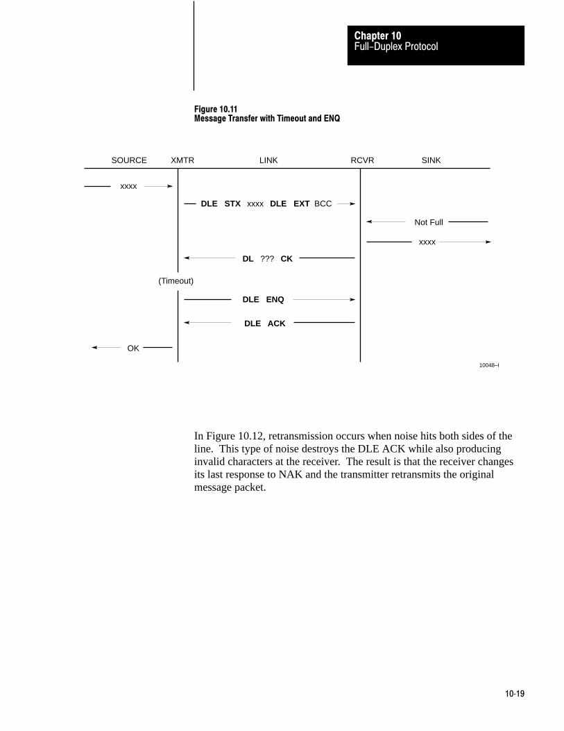
Full-Duplex ProtocolChapter 10
10�19
Figure 10.11Message Transfer with Timeout and ENQ
Not Full
DLE ACK
OK
xxxx
DLE ENQ
xxxx
SOURCE XMTR LINK RCVR SINK
10048–I
DL
DLE STX xxxx DLE EXT BCC
(Timeout)
??? CK
In Figure 10.12, retransmission occurs when noise hits both sides of theline. This type of noise destroys the DLE ACK while also producinginvalid characters at the receiver. The result is that the receiver changesits last response to NAK and the transmitter retransmits the originalmessage packet.
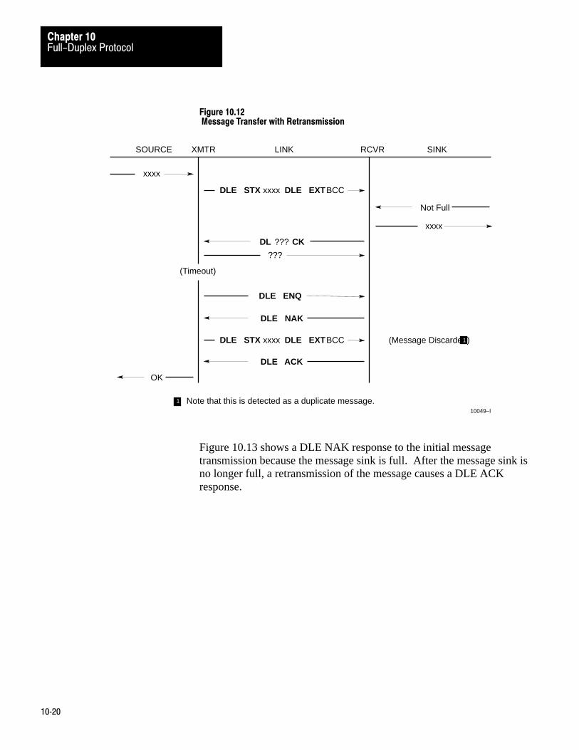
Full-Duplex ProtocolChapter 10
10�20
Figure 10.12 Message Transfer with Retransmission
Not Full
DLE NAK
OK
xxxx
DLE ENQ
xxxx
SOURCE XMTR LINK RCVR SINK
10049–I
DL
DLE STX xxxx DLE EXTBCC
(Timeout)
??? CK
???
DLE STX xxxx DLE EXTBCC
DLE ACK
(Message Discarded)1
1 Note that this is detected as a duplicate message.
Figure 10.13 shows a DLE NAK response to the initial messagetransmission because the message sink is full. After the message sink isno longer full, a retransmission of the message causes a DLE ACKresponse.
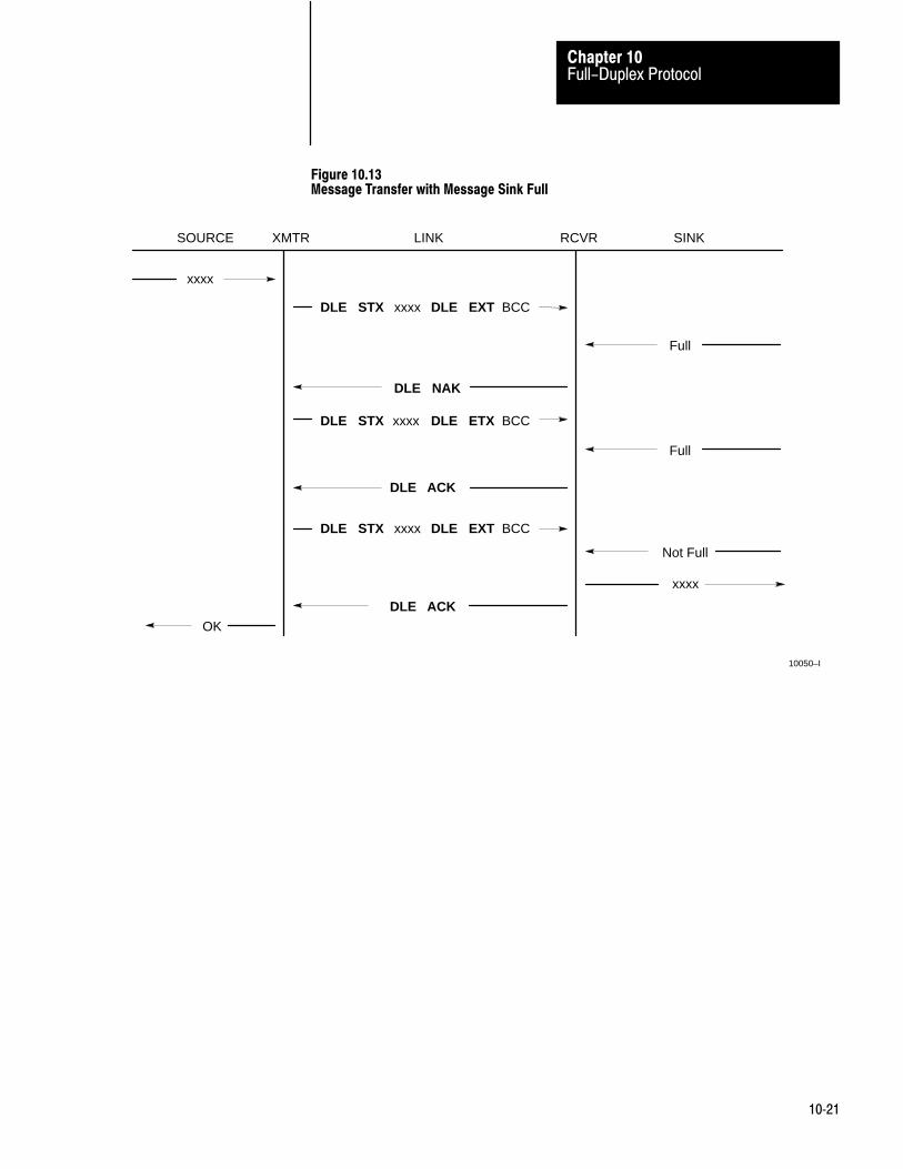
Full-Duplex ProtocolChapter 10
10�21
Figure 10.13Message Transfer with Message Sink Full
Not Full
OK
xxxx
xxxx
SOURCE XMTR LINK RCVR SINK
10050–I
DLE NAK
DLE STX xxxx DLE EXT BCC
DLE STX xxxx DLE EXT BCC
DLE ACK
DLE STX xxxx DLE ETX BCC
DLE ACK
Full
Full

Full-Duplex ProtocolChapter 10
10�22
If you were to connect a line monitor to the wires between station A andB, and only the A to B subsystem were active, you could observe thefollowing:
Examples
Normal Message
Path 1: DLE STX xxxDLE ETX BCC DLE STXxxxxDLE ETX BCC
Path 2: DLE ACK DLE ACK
Message with parity or BCC error and recovery
Path 1: DLE STXxx???xxDLE ETX BCC DLE STXxxxxDLE ETX BCC
Path 2: DLE NAK DLE ACK
Message with ETX destroyed
Path 1: DLE STXxxxxx????[timeout] DLE ENQ DLE STXxxxxDLE ETX BCC
Path 2: DLE NAK DLE ACK
Good message but ACK destroyed
Path 1: DLE STXxxxDLE ETX BCC [timeout] DLE ENQ DLE STXxxx etc.
Path 2: DL???CK DLE ACK
Messages being sent in both directions
Path 1: DLE STXxxxDLE ETX BCC DLE STXxxxxDLE ETX BCC DLE STX
Path 2: DLE ACK DLE ACK
Path 3: DLE STXxxx xxxxDLE ETX BCC DLE STX
Path 4: DLE ACK
Combined –
Circuit AB:DLE STXxxxDLE ETX BCC DLE STXxxxxDLE ETX BCC DLE ACK DLE STX
Circuit BA: DLE STXxxxDLE ACKxxxxDLE ETX BCC DLE ACK DLE STX
embedded response
ACK on AB delayed slightly because ETX BCC are indivisible

Full-Duplex ProtocolChapter 10
10�23
Embedded Response Option
To simplify the design of the receiver in some cases, you can disabletransmission of embedded responses by turning off the embeddedresponse switch. If you turn this switch off, the 1775–KA module’smultiplexer cannot embed response codes while sending a message.Instead,it delays sending response codes until after it sends the next DLEETX BCC sequence.

Chapter
11
11�1
Half-Duplex Protocol
Half–duplex protocol serves as an alternate to full–duplex protocol. Half–duplex is synonymous with polled–subscriber mode. To select thehalf–duplex mode, you select the polled subscriber mode with LIST(chapter 2).
Half–duplex protocol differs from the full–duplex mode in two ways:
Half–duplex protocol provides for polling of slave stations. Half–duplex protocol does not allow embedded responses.
Half–duplex protocol is for one master and one or more slaves. You mustuse MODEMS for this type of link (unless there is only one slave). The1775–KA module has slave mode capability only; you must provide themaster function through a computer.
For peer–to–peer communication, half–duplex protocol provides a lesseffective use of resources than full–duplex, but it is easier to implement.You should use half–duplex protocol if:
You are using multidrop baseband MODEMS to connect multiple slavestations to a single master computer
You are using MODEMS that have only half–duplex capability You are willing to sacrifice data throughput in exchange for ease of
implementation
One environment for half–duplex protocol is a multidrop link with allstations interfaced through half–duplex modems. The actual nature of thelink does not matter much, as long as the MODEMS supportrequest–to–send, clear–to–send, and data–carrier–detect signals. If youuse dial–up MODEMS, they must also support data–set–ready anddata–terminal–ready; otherwise, you should jumper data–set ready todata–terminal–ready at the 1775–KA module.
You may have from 2 to 256 stations simultaneously connected to a singlemultidrop link. Each station must have a receiver connected to the circuitand a transmitter that can be enabled or disabled by request–to–send.
Half-Duplex Protocol
Multidrop Link

Half-Duplex ProtocolChapter 11
11�2
You must program a computer to serve as a master that controls whichstation has access to the link. All other stations are slaves and must waitfor permission from the master before transmitting. Each slave station hasa unique station number from 0 to 376 octal. The number 377 is abroadcast address. When the master sends a message addressed to 377,all slaves receive it.
The master can send and receive messages to and from each station on themultidrop link. If the master is programmed to relay messages, then slavestations on the multidrop link can engage in peer–to–peer communication.
Your multidrop link may be either a two–circuit system (master sends andslaves receive on one circuit, slaves send and master receives on theother), or a one–circuit system (master and slaves send and receive on thesame circuit).
You may use a half–duplex, dial–up modem to connect the 1775–KAmodule to the multidrop link. The modem must signal data–carrier–detectat least once every 8 seconds. If it does not, the module will hang up. Ona dedicated line, you can jumper lines 6,8, and 11 at the 1775–KA moduleto prevent the module from hanging up.
You cannot use multiple masters unless one master is limited to acting asa backup to the other, and does not communicate until the primary is shutdown.
Half–duplex protocol is a character oriented protocol that uses thefollowing ASCII control characters:
Control character Hexdecimal Code
SOH (Start of Header) 01
STX (Start of Text) 02
ETX (End of Text) 03
EOT (End of Transmission) 04
ENQ (Enquiry) 05
ACK (Acknowledge) 06
DLE (Data Link Escape) 10
NAK (Negative Acknowledge) 15
Transmission Codes

Half-Duplex ProtocolChapter 11
11�3
These ASCII control characters are extended to 8 bits by adding a zero forbit 7. See ANSI X3.4, CCITT V.3, or ISO 646 for the standard definitionof these characters.
Additionally, a block check character (BCC) is used at the end of eachtransmission packet for error checking. This byte can be any value from00 to FF hex.
The term code means (in the following paragraphs) an indivisiblesequence of one or more bytes having a specific meaning to the protocol.Indivisible means that the component bytes of a code must be sent oneafter another with no other bytes inserted between them. It does not referto the timing of the bytes. (This definition has less significance than forfull–duplex protocol, since there is no multiplexing of transmission codesin half–duplex protocol).
Half–duplex protocol uses the following control codes:
DLE SOH DLE STX DLE ETX BCC/CRC DLE ACK DLE NAK DLE ENQ DLE EOT
Half–duplex protocol also uses the following link–layer data codes:
Data (single bytes having values 00–0F and 11–FF hex) DLE DLE (to represent the value 10 hex) Link–layer address code STN (station identifier)
We can group these codes into two classes according to their use:
1. message codes issued from a station sending a message (or poll)
2. response codes issued from a station receiving a message (or poll).
These codes are issued by a station transmitting a message (or poll):
DLE SOH – indicates the start of a message packet. STN – helps to designate the station number. When the 1775–KA is
communicating with another station as a peer, the STN = DST. If the

Half-Duplex ProtocolChapter 11
11�4
1775–KA is just one of several stations on a Data Highway, the STNtogether with the DST identifies the 1775–KA station
DLE STX – separates the data link protocol information from thenetwork packet.
Link–layer data: (00–0F and 11–FF hex) – encodes the bytes of thenetwork packet.
DLE DLE – encodes the value 10 hex in the network packet. This isnecessary to distinguish a text code of 10 hex from a DLE control codeof 10 hex.
DLE ETX BCC – terminates a message or polling packet. DLE ENQ – indicates the start of a polling packet.
Response codes from station receiving a message (or poll):
DLE ACK – signals that the receiver has successfully received the lastmessage sent.
DLE NAK – serves as a global link reset command. It causes all slavesto cancel all messages they have ready to transmit to the master. The1775–KA module responds to this by writing error code 84 into itserror word in the PC data table.
DLE EOT – is the response that a slave sends to a poll from the masterwhen the salve has no messages to send.
Half–duplex protocol uses three types of transmissions:
Polling packet Master message packet Slave message packet
The master station transmits both polling packets and master messagepackets, while slave stations transmit slave message packets.
Figure 11.1 illustrates the formats of these packets. Note that the slavemessage packet has the same format as the full–duplex message packet.The master message packet is the same as the slave message packetexcept that it is prefixed with DLE SOH and an address code to specify aslave station number.
At the end of each polling packet is a BCC byte. At the end of eachmessage packet is a one–byte BCC field.
Link-Layer Packets

Half-Duplex ProtocolChapter 11
11�5
Figure 11.1Formats for Half-Duplex Protocol
DLE ENQ STN BCC
a) Polling Packet
CMD STS FNC ADDR DATA
DST SRC CMD STS TNSData
(From Application Layer)
DLE STX Data(From Network Layer) DLE ETX BCC
b) Slave Message Link Packet
FromApplicationLayer
FromNetworkLayer
FromApplicationLayer
FromNetworkLayer
CMD STS FNC ADDR DATA
DST SRC CMD STS TNSData
(From Application Layer)
DLE SOH STN DLE STXData
(From Network Layer) DLE ETX BCC
c) Master Message Link Packet
10051–I
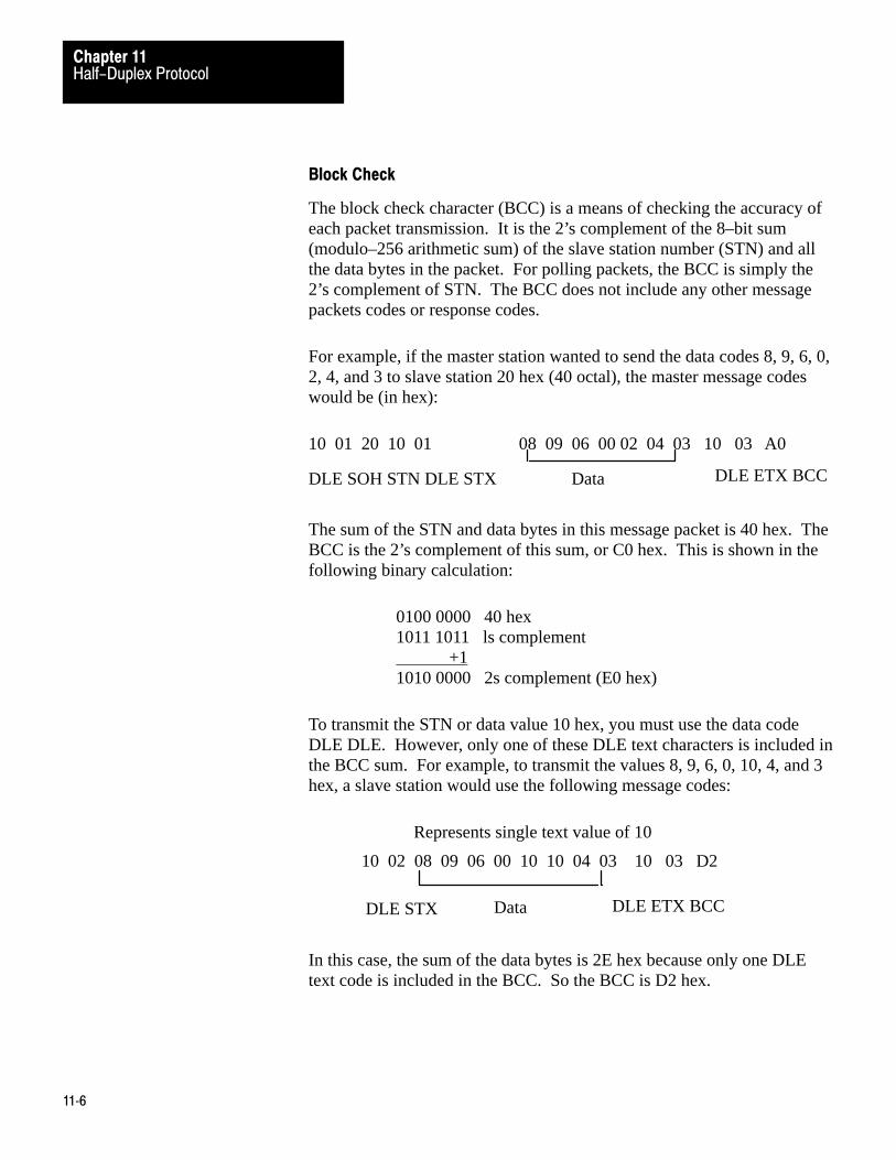
Half-Duplex ProtocolChapter 11
11�6
Block Check
The block check character (BCC) is a means of checking the accuracy ofeach packet transmission. It is the 2’s complement of the 8–bit sum(modulo–256 arithmetic sum) of the slave station number (STN) and allthe data bytes in the packet. For polling packets, the BCC is simply the2’s complement of STN. The BCC does not include any other messagepackets codes or response codes.
For example, if the master station wanted to send the data codes 8, 9, 6, 0,2, 4, and 3 to slave station 20 hex (40 octal), the master message codeswould be (in hex):
10 01 20 10 01
DLE SOH STN DLE STX
08 09 06 00 02 04 03 10 03 A0
Data DLE ETX BCC
The sum of the STN and data bytes in this message packet is 40 hex. TheBCC is the 2’s complement of this sum, or C0 hex. This is shown in thefollowing binary calculation:
0100 0000 40 hex1011 1011 ls complement +11010 0000 2s complement (E0 hex)
To transmit the STN or data value 10 hex, you must use the data codeDLE DLE. However, only one of these DLE text characters is included inthe BCC sum. For example, to transmit the values 8, 9, 6, 0, 10, 4, and 3hex, a slave station would use the following message codes:
Represents single text value of 10
10 02 08 09 06 00 10 10 04 03 10 03 D2
DLE STX Data DLE ETX BCC
In this case, the sum of the data bytes is 2E hex because only one DLEtext code is included in the BCC. So the BCC is D2 hex.

Half-Duplex ProtocolChapter 11
11�7
Each station on the multidrop link must contain a software routine, knownas a transceiver, that can both transmit and receive message packets. The1775–KA module already contains a slave transceiver routine, so it willfunction as a slave station if you select Polled–Subscriber Mode withLIST (chapter 2). To establish master station, you have to program atransceiver routine at a computer. In addition to transmitting andreceiving message packets, the master transceiver must also be able totransmit polling packets.
Note that you can program separate transmitter and receiver routinesinstead of a single transceiver. For purposes of the discussion here,however, we assume that the transceiver is a single software routine.
Figure 11.2 illustrates the operation of master and slave transceivers. Tofully define the protocol environment, you must tell the master transceiverwhere to get the messages it sends and how to dispose of messages itreceives. These are implementation–dependent functions that we call themessage source and the message sink respectively.
We assume that the message source supplies one network packet at a timeupon request from the transceiver, and that the source has to be notifiedabout the success or failure of transfer before supplying the next.Whenever the transceiver has received a link packet successfully, itattempts to give the network packet portion to the message sink. Themessage sink may be full. The message sink must notify the transceiverwhen it is full.
Protocol Environment Definition

Half-Duplex ProtocolChapter 11
11�8
Figure 11.2Slave Transceiver
Software Software
Hardware
SOURCE
NetworkPacket
NetworkPacket
OK
Full
TRANSMITTER
RECEIVER
SINK
10052-I
SINK
NetworkPacket
MASTER SLAVESOURCE
NetworkPacket
Full
OK
Link
To Other Slaves
Message Characteristics
Half–duplex protocol places the following restrictions on the networkpacket that is submitted to the link layer for transfer.
The size of a valid network packet is 6 bytes minimum, and 250 bytesmaximum.
The first byte of a network packet must be the station number of thereceiver station (see DST in chapter 12). The receiver ignoresmessages that do not contain the correct station number.
As part of the duplicate message detection algorithm, the transceiverchecks the second, third, fifth, and sixth bytes of each network packet.At least one of these bytes of the current network packet must differfrom the corresponding byte of the previous network packet in order forthe transceiver to act upon the current network packet. Otherwise, thetransceiver assumes that the current network packet is a retransmissionof the previous network packet, so it discards the current networkpacket.
Master Polling Responsibilities
You may vary the master polling algorithm, depending on how muchactivity you expect on your network.

Half-Duplex ProtocolChapter 11
11�9
The master should poll each slave repeatedly until that slave hastransmitted all of its messages. The master should then send anymessages it has for that slave. Then the master can poll the next slave inthe same way.
If a slave station fails to respond to a poll, the master should remove thatslave from the list of active slaves. To save time, the master should pollonly the active slaves on a regular basis. The master should poll theinactive slaves occasionally to see whether they will respond.
It is best not to allow the master station’s transceiver to relay messagesdirectly from one slave station to another. Instead, the transceiver shouldfunnel all received messages to the message sink (network layer). Thenetwork layer can then analyze the messages and retransmit any that areaddressed to a slave station.
Figure 11.3 is a flowchart which gives a simplified view of an example ofsoftware logic for implementing half–duplex protocol from the masterstation’s point of view.

Half-Duplex ProtocolChapter 11
11�10
Figure 11.3Implementation of Half-Duplex Protocol
XCVR
Select Station
Poll Selected Station
Start Timeout
Receive No Receive YesMessage
No
No YesYes
Set Active Station Flag
Get Message from
Send Message
Start Timeout
Received Yes
No
3No
Tell Network Layer
Yes
Remove Station
Active
Yes
3
Yes
Duplicate Yes
No
Give Message
Send DLE ACK
10053–I
DLE EOT Message OK?
Network Layer
DLE ACK
Timeoutsfor this
of Failure
Station
Timeoutsfor this
from Active List
Message
to Network Layer
No
No
NetworkLayer has
?
No
Yes
?
Message?
?
Poll?
?
Message tosend?

Half-Duplex ProtocolChapter 11
11�11
Transceiver Actions
Since the transceiver receives “dirty” input from the physical world, itmust be capable of responding to many adverse situations. Some of thethings that can conceivably happen are listed here:
The message sink can be full, leaving the transceiver with nowhere toput message.
A message can contain a parity error. The BCC can be invalid. The DLE SOH, DLE STX, or DLE ETX BCC may be missing. The message can be too long or too short. A spurious control or data code can occur outside a message. A spurious control code can occur inside a message. Any combination of the above can occur. The DLE ACK response can be lost, causing the transceiver to send a
duplicate copy of a message that has already been passed to themessage sink.
Each slave station is in a passive mode until it receives a DLE ENQ orDLE SOH code. While in a passive mode a slave ignores anytransmission code that is not DLE ENQ or DLE SOH.
When a slave receives a DLE SOH, it resets its BCC accumulator andmessage receiving buffer. The next code it receives must be its specificstation number of the global station number 377 (octal). If the packetdoes not contain the appropriate station number, the slave ignores it andwaits for the start of a new transmission.
If a slave receives a message packet with the appropriate station number,it adds the value of that station number to its accumulated BCC. If thenext characters after the station number are DLE STX, then the slavetransceiver starts storing the incoming link–layer data in a buffer. Thetransceiver stores all data codes in the buffer and adds these code valuesto the accumulated BCC. Even if the storage buffer overflows, thetransceiver continues summing the BCC, while discarding the data.
The slave also sets an error flag to indicate the occurrence of a parity,buffer overrun, message framing, or MODEM handshaking error. Whenthe slave gets a DLE ETX BCC, it checks this error flag, the BCC, and themessage size. If any of these tests fail, the slave ignores the message.
If the current message packet passes the above tests, the slave next beginsthe duplicate message detection process. In this process, the slave

Half-Duplex ProtocolChapter 11
11�12
compares the SRC, CMD, and both TNS bytes with the correspondingbytes of the previous message received. If these bytes are the same, theslave discards the current message and sends a DLE ACK.
If the current message differs from the previous one, the slave next teststhe state of the message sink. If the message sink is full, the transceiverdiscards the current message and does not respond. Otherwise, thetransceiver:
Forwards the current link–level data to the message sink Keeps a copy of the first six bytes of the current link–level data for
purposes of duplicate message detection Sends a DLE ACK
While waiting to receive a message, a slave station could receive a pollingpacket that begins with a DLE ENQ sequence. The slave will ignore thepoll if the polling packet does not contain the slave’s station number or ifthe BCC is the polling block is incorrect. If the poll is valid, then one ofthree conditions can exist:
The slave is still holding a message that it had transmitted previouslybut had not been acknowledged by the master station. There is a limiton the number of times the slave will attempt to transmit a message. Ifthis limit has been exceeded, the slave responds to this by writing anerror code into its error word in the PC data table, and then tries totransmit the next message from the message source. If the NAK limitis not exceeded, the slave tries to retransmit the current message.
If the slave does not currently have a message to send, it tries to get onefrom the message source. If a message is available, the transceiverinitializes its retry counter and transmits the message in response to thepoll.
If not message is available, the transceiver responds to a poll bytransmitting a DLE EOT.
To transmit a message, the slave transceiver uses the same message blockformat as the full–duplex format (section 10.3.2). After sending amessage, the transceiver keeps a copy of that message until it receives aDLE ACK from the master station, or until its retry limit is exceeded.
When the slave transceiver receives a DLE ACK, it discards the currentmessage. The next time the slave is polled, it will send the next messageavailable from the message source. If no message is available in themessage source, the slave responds to a poll with DLE EOT.
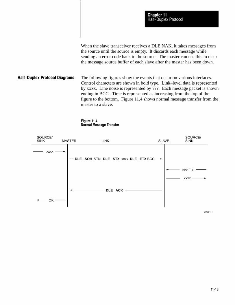
Half-Duplex ProtocolChapter 11
11�13
When the slave transceiver receives a DLE NAK, it takes messages fromthe source until the source is empty. It discards each message whilesending an error code back to the source. The master can use this to clearthe message source buffer of each slave after the master has been down.
The following figures show the events that occur on various interfaces.Control characters are shown in bold type. Link–level data is representedby xxxx. Line noise is represented by ???. Each message packet is shownending in BCC. Time is represented as increasing from the top of thefigure to the bottom. Figure 11.4 shows normal message transfer from themaster to a slave.
Figure 11.4Normal Message Transfer
Not Full
OK
xxxx
xxxx
SINK MASTER LINK SLAVE SINK
10054–I
DLE ACK
DLE STX xxxx DLE ETX BCC
SOURCE/ SOURCE/
DLE SOH STN
Half-Duplex Protocol Diagrams

Half-Duplex ProtocolChapter 11
11�14
Figure 11.5 shows a message transfer in which the BCC was invalid.After a timeout, the message is retransmitted. After the retransmission theresponse is DLE ACK.
Figure 11.5Message Transfer with Invalid BCC
Not Full
OK
xxxx
xxxx
SINK MASTER LINK SLAVE SINK
1005–I
DLE ACK
DLE STX ??? DLE ETX BCC
SOURCE/ SOURCE/
DLE SOH STN
DLE STX xxxx DLE ETX BCCDLE SOH STN
(Timeout)
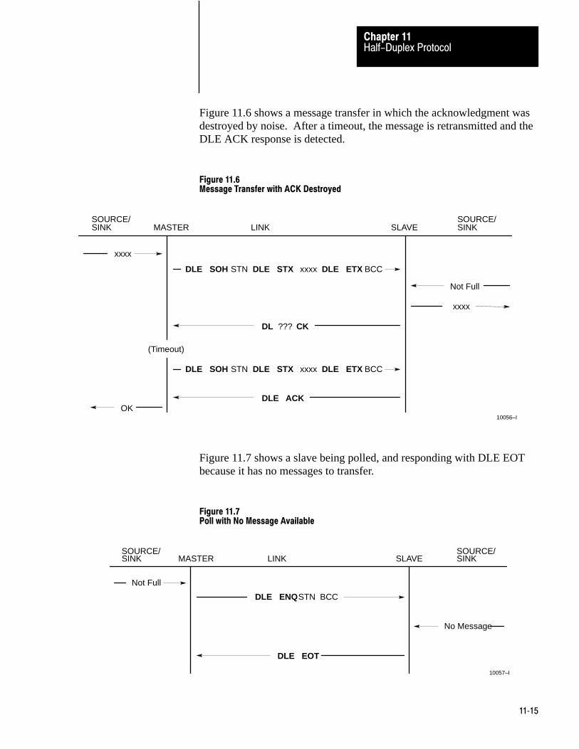
Half-Duplex ProtocolChapter 11
11�15
Figure 11.6 shows a message transfer in which the acknowledgment wasdestroyed by noise. After a timeout, the message is retransmitted and theDLE ACK response is detected.
Figure 11.6Message Transfer with ACK Destroyed
Not Full
OK
xxxx
xxxx
SINK MASTER LINK SLAVE SINK
10056–I
DLE ACK
SOURCE/ SOURCE/
DLE STX xxxx DLE ETX BCCDLE SOH STN
(Timeout)
DL ??? CK
DLE STX xxxx DLE ETX BCCDLE SOH STN
Figure 11.7 shows a slave being polled, and responding with DLE EOTbecause it has no messages to transfer.
Figure 11.7Poll with No Message Available
No Message
Not Full
SINK MASTER LINK SLAVE SINK
10057–I
DLE EOT
SOURCE/ SOURCE/
BCCDLE ENQSTN

Half-Duplex ProtocolChapter 11
11�16
Figure 11.8 shows a slave being polled, and answering with a message.Because a block check error is found, the master does not acknowledge;instead, it sends the poll to the slave again. Since the slave did not receivean acknowledgement to its first message transmission, it retransmits thesame message in answer to the second poll. The master receives thesecond transmission of the message with no error and responds with DLEACK.
Figure 11.8Poll with Message Returned
xxxx
xxxx
OK
Not Full
SINK MASTER LINK SLAVE SINK
10058–I
DLE ACK
SOURCE/ SOURCE/
BCCDLE ENQ STN
DLE STX xx???xx DLE EXTBCC
BCCDLE ENQ STN
DLE STX xxxx DLE EXT BCC Same Message
Figure 11.9 shows a slave unable to receive the acknowledgement fromthe master after the master successfully received the message from theslave. Sometime later when the master polls that same slave again, theslave sends the same message again. The master responds with DLEACK, but discards the received transmission block because it detects it tobe a duplicate message received from that slave. With multiple slaves, toimplement this duplicate message detection, the master must do either ofthe following:
Poll a station repeatedly (without polling any other station until itreceives a DLE EOT to be sure it has detected any retransmissions.

Half-Duplex ProtocolChapter 11
11�17
If each station is polled only once per cycle, the master must keep arecord of the first 6 link–level data bytes of the last transmission fromeach station, since other stations may transfer messages betweenretransmissions from a given station.
Figure 11.9Duplicate Message Transmission
xxxx
xxxx
OK
Not Full
SINK MASTER LINK SLAVE SINK
10059–I
DLE ACK
SOURCE/ SOURCE/
BCCDLE ENQ STN
DLE STX xxxx DLE EXT BCC
BCCDLE ENQ STN
DLE STX xxxx DLE EXT BCC
Not Full
DL ??? CK
Sometime Later ...
(Discard Retransmission)
When a slave station fails to respond to a message from the master, youshould poll the slave to see if it is there. If it answers the poll with a DLEEOT but consistently fails to ACK the master’s message, the slave’smessage sink is probably full. If the slave answers with DLE EOT to apoll, you should wait for the slave’s receiver buffers to clear. Thissituation is illustrated in figure 11.10.

Half-Duplex ProtocolChapter 11
11�18
Figure 11.10Message Sink Full, Case 1
Full
OK
xxxx
xxxx
SINK MASTER LINK SLAVE SINK
10060–I
DLE ACK
SOURCE/ SOURCE/
BCCDLE SOH STN
DLE EQT
BCCDLE ENQ STN
Not Full
Sometime Later ...
(Timeout)
DLE STX xxxx DLE ETX
BCCDLE SOH STN DLE STX xxxx DLE ETX
No Message
Not Full

Half-Duplex ProtocolChapter 11
11�19
When a slave station’s message source and sink share a common memorypool (as in the 1775–KA module) it may be that the message sink fullindication results from an abundance of messages in the message source,which uses up all free pool memory. In this case, the memory can befreed up by receiving messages from that slave station. Waiting for thememory to clear by the action of the slave station alone may not work,since it could be that the only way to fee up space is for the slave to send amessage to the master. This situation is illustrated in Figure 11.11.
Figure 11.11Message Sink Full, Case 2
Full
OK
xxxx
xxxx
SINK MASTER LINK SLAVE SINK
10061–I
DLE ACK
SOURCE/ SOURCE/
BCCDLE SOH STN
DLE STX
BCCDLE ENQ STN
Not Full
(Timeout)
DLE STX xxxx DLE ETX
BCCDLE SOH STN DLE STX xxxx DLE ETX
xxxx
Not Full
xxxx
xxxx DLE ETX BCC

Half-Duplex ProtocolChapter 11
11�20
When monitoring half–duplex protocol on a two–wire link, you need tomonitor only one line. the example below shows a message sent by themaster and a reply sent by the slave in answer to a poll. Slave responsesare in bold.
Message from master to slave:
DLE SOH STN DLE STX xxxx DLE ETX BCC DLE ACK
Message sent from slave to master in answer to poll:
DLE ENQ STN BCC DLE STX xxxx DLE ETX BCC DLE ACK
Poll with a DLE EOT answer:
DLE ENQ STN BCC DLE EOT
Line Monitoring
Chapter
12
12�1
The Network and Application Layer Protocol
The network protocol defines a network packet format for interactionbetween application programs. The link protocol merely serves to carrydata blocks between two applications, regardless of which data linkprotocol (half or full– duplex) you use. The application programs may belocated at opposite ends of a point–to–point full duplex link, or atdifferent points on a multidrop half– duplex link. The network protocolcan even handle the transfer of messages between application programs inthe same device.
The network layer ignores the internal functioning of data link protocols.It requires that the data link driver accepts a message for delivery, tries tosend it, and indicates whether it was delivered.
Program And Message Types
The network protocol was designed on the assumption that applicationprograms are of two types: command initiators and command executors.Corresponding to this division there are two message types:
Command messages – initiated by command initiators and carried overthe network to a command executor.
Reply messages – the replies that command executors send tocommand initiators.
For each command message there is normally one and only one reply. (Arare exception occurs when the data link delivers a message but receivesno acknowledgement to verify delivery. At the command initiator, thenetwork layer sends a reply command executor receives and executes thecommand packet, and sends a single reply message to the commandinitiator. In any case, the command executor generates only one replymessage for each command it receives.)
If the network layer of the command initiator station cannot deliver acommand to another station, it generates a reply message with an errorcode in its own application layer. If a reply cannot be delivered, thenetwork layer destroys it.
Network Layer
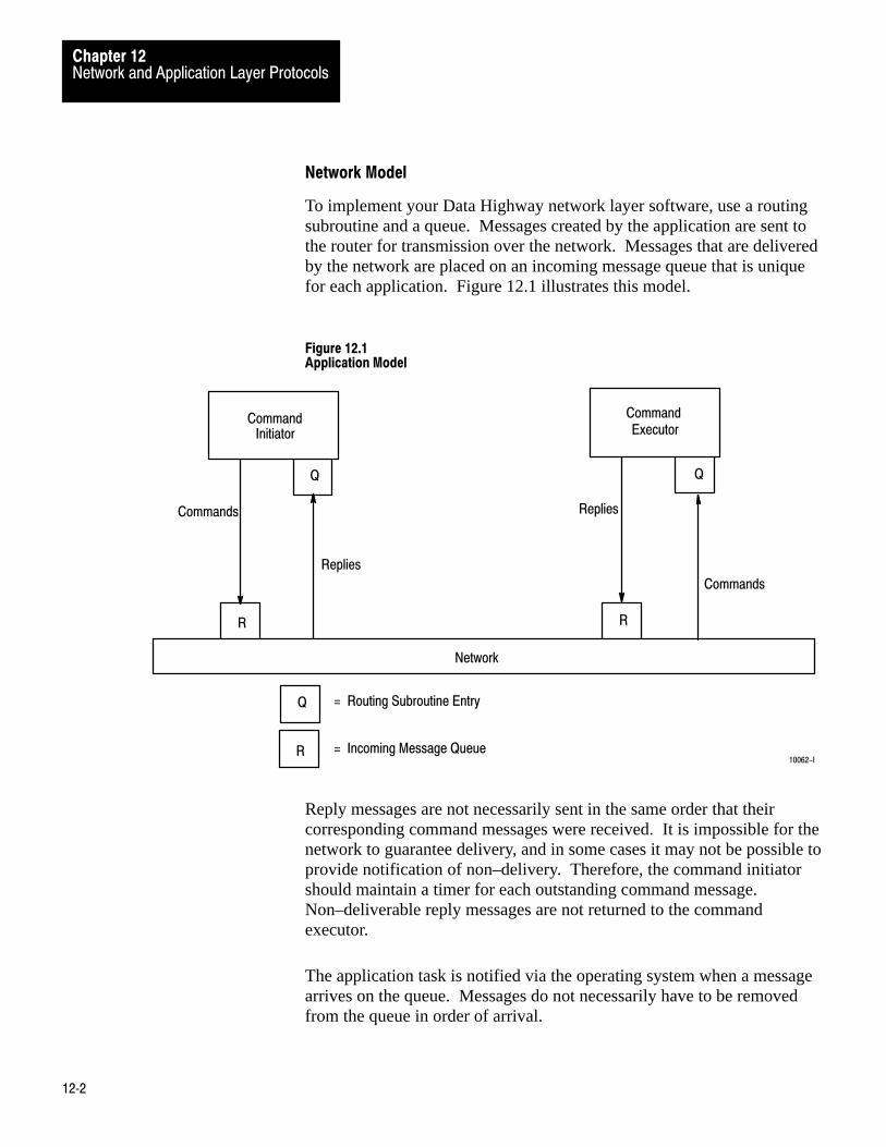
Network and Application Layer ProtocolsChapter 12
12�2
Network Model
To implement your Data Highway network layer software, use a routingsubroutine and a queue. Messages created by the application are sent tothe router for transmission over the network. Messages that are deliveredby the network are placed on an incoming message queue that is uniquefor each application. Figure 12.1 illustrates this model.
Figure 12.1Application Model
Command
Q
R
Commands
Replies
Command
Q
Replies
Commands
R
Network
Initiator Executor
Q
R
= Routing Subroutine Entry
= Incoming Message Queue10062-I
Reply messages are not necessarily sent in the same order that theircorresponding command messages were received. It is impossible for thenetwork to guarantee delivery, and in some cases it may not be possible toprovide notification of non–delivery. Therefore, the command initiatorshould maintain a timer for each outstanding command message.Non–deliverable reply messages are not returned to the commandexecutor.
The application task is notified via the operating system when a messagearrives on the queue. Messages do not necessarily have to be removedfrom the queue in order of arrival.

Network and Application Layer ProtocolsChapter 12
12�3
Network Packet Fields
As we discussed the communication protocol used on the data link, wedescribed control characters framing the network packet. Here at thenetwork level, you must generate the network packet. In this protocol thenetwork packet characters are generated directly from binary coded bytesof data. This provides faster throughput on the link than if this data werecoded into ASCII characters.
Figure 12.2 shows the general format of the network packet for acommand message. Figure 12.3 shows the general format of the networkpacket for a reply message. Note that bytes are shown from left to right inthe order in which they are transmitted on the link.
Note that the only difference between the network packet for a commandmessage and the network packet for a reply message is in the high nibbleof the CMD byte.
Figure 12.2Command Message Packet Format
CMD STS FNC ADDR DATA
DST SRC CMD STS TNSData
(From Application Layer)
FromApplicationLayer
10063–I
x
0 x
NetworkLayerPacket

Network and Application Layer ProtocolsChapter 12
12�4
Figure 12.3Reply Message Packet Format
CMD STS DATA
DST SRC CMD STS TNSData
(From Application Layer)
FromApplicationLayer
10064–I
x
4 x
NetworkLayerPacket
Legend: x = low hex digit of CMD byte supplied by application layer
DST and SRC
The DST (destination) byte is the number of the station that receives thenetwork packet. The SRC (source) byte is the number of the station thatsent the packet. There are 255 possible station numbers from 0 to 254decimal. You reverse the DST and SRC of the command message to formthe DST and SRC of the corresponding reply message.
CMD (High Nibble)
The high nibble of the CMD (command) byte is supplied by the networklayer. Bit 6 (26 value) of the CMD byte is the command/reply indicator.It is 0 for command messages and 1 for reply messages. Therefore thehigh hex digit of the command byte is 0 for command messages and 4 forreply messages. (The low nibble comes from the application layer).
STS (Low Nibble)
The low nibble of the STS (status) byte is supplied by the network layer.In a command message, this field is set to zero. In a reply messagereporting no error or a remote error, this field is also set to zero. (Thehigh nibble comes from the application layer.)

Network and Application Layer ProtocolsChapter 12
12�5
If the network layer of your computer cannot deliver a command toanother station, it writes a local error code into this field to generate areply message which it returns to the command indicator in yourapplication layer. All error codes are listed in appendix B.
TNS
The two TNS (transaction) bytes contain a unique 16–bit transactionidentifier field. A complete transaction consists of a command messageand its corresponding reply message. The TNS value in the reply must bethe same as the TNS value in its associated command. This enables thecommand initiator to associate an incoming reply message with one of thecommand messages it transmitted previously.
For command messages transmitted by a PC station, the 1775–KAmodule assigns the TNS values. For each command message transmittedby your computer station, your application programs must assign a unique16–bit transaction number. A simple way to generate the transactionnumber is to maintain a 16–bit counter in your application program.Increment the counter every time your command initiator (applicationprogram) creates a new message, and store the counter value in the twoTNS bytes of the new message.
When your computer program receives a reply to one of its commandmessages, it can use the TNS value to tie the reply message to itscorresponding command. If the TNS value of a reply message matchesthe TNS value of a command message, then that reply is the appropriateone for that command.
Whenever your computer network layer receives a command fromanother station, it should copy the TNS bytes of the command messageinto the same bytes of the corresponding reply message. Do not changethe TNS value in a reply message. If you do, the command initiator willnot be able to match its command to the corresponding reply message.
Note that the low byte (least significant bits) of your TNS value will betransmitted across the link before the high byte (most significant bits).
At any instant, the combination of SRC, CMD, and TNS values aresufficient to uniquely identify every message packet in transit forduplicate message detection. At least one of these fields in the currentmessage must be different, the command executor ignores the current

Network and Application Layer ProtocolsChapter 12
12�6
message. During an upload or download, the TNS value is the only wayto distinguish between the physical read or write reply messages.
Recall from chapter nine that the application layer provides the DataHighway commands that you use to transfer data and manage thenetwork. This function is provided by the command initiators andcommand executors.
At the application layer, the command initiators are responsible for:
creating a message packet and submitting that packet to the networklayer
maintaining the sequence number and the timeout accepting the reply canceling the timeout and sequence number destroying the reply message packet when it is no longer needed
At the application layer, the command executors must:
create the reply message packet copy over certain information from the command fill in any reply information submit the packet to the network destroy the command packet
Application programs communicate by sending information back andforth in the command, status, and data fields of network packets.Application protocols may vary depending on the types of applicationprograms that are communicating.
Application Message Fields
Figure 12.2 shows the general format of the application fields for acommand message. Not all command messages have FNC, ADDR, orDATA bytes.
Figure 12.3 shows the general format of the application fields for a replymessage. Not all reply messages have DATA bytes.
In addition to the application layer fields shown in these figures, some ofthe PLC–3 command messages also contain these application layer fields:
EXT STS (extended status) Packet Offset
Application Layer

Network and Application Layer ProtocolsChapter 12
12�7
Word Offset TOTAL TRANS (total transaction size)
Appendix A lists the message formats (command and reply) of everycommand the PLC–3 can send or receive.
CMD and FNC (command and function)
For these message formats which include an FNC byte, the low nibble ofthe CMD (command) byte together with the FNC (function) byte definewhat action the command executor at the destination station will perform.For those message formats which do not include an FNC byte, the CMDbyte alone defines what action the command executor at the destinationstation will perform. The hexidecimal values of the CMD and FND bytesare listed in Table 12.A for each of the types of messages that can betransmitted across this link.
Bits 0 through 3 of the CMD byte must be the same in the reply messageas it is in the corresponding command message. In currentimplementations this is either a command code or a command executorselector. The application program must always copy this field from thecommand to the reply message.
Network and Application Layer ProtocolsChapter 12
12�8
Table 12.AThe commands that the PLC-3 can send and/or receive, and the hexadecimal values for theCMD and FNC bytes
Devices thatcan send thecommand
CommandType
Command NameCommandMessage
(Hex)CMD+ FNC+
ReplyMessage
(Hex)CMD+
PLC-3 orRS-232-C[1]
device
�Basic"[2] Protected Bit WriteProtected Block WriteUnprotected Bit WriteUnprotected Block ReadUnprotected Block Write
0200050108
nonenonenonenonenone
4240454148
PLC-3 orRS-232-Cdevice
PLC-3commands
Bit WritesFile ReadFile WriteWord Range ReadWord Range Write
0F0F0F0F0F
0204030100
4F4F4F4F4F
RS-232-Cdevice
PLC-3Upload/
DownloadCommands
Download RequestRestart RequestShutdown RequestUpload Request
0F0F0F0F
050A0706
4F4F4F4F
RS-232-Cdevice
Privileged[3] Physical ReadPhysical Write
0F0F
0908
4F4F
RS-232-Cdevice
Diagnostic Counter ResetLoopReadStatusSet ENQsSet NAKsSet TimeoutSet Variables
0606060606060606
0700010306050402
4646464646464646
[1] RS-232-C device means a computer or intelligent terminal.[2] The �Basis" commands can be sent to any Allen-Bradley PC. These commands are sometimes called PLC/PLC-2 commands, but all
Allen-Bradley PC's can receive them. The PLC, PLC-2 family, and PLC-3 processors can also send these commands as well as receive them.[3] Allen-Bradley recommends using these commands for uploading or downloading only. To write or read specific words or bits use the �basic"
commands or the PLC-3 commands.
STS (status)
The high nibble of the STS (status) byte is supplied by the applicationlayer. In command messages the STS byte is set to zero.
In reply messages the STS is used for reporting either application ornetwork error codes. A value of zero should be interpreted as no error(that is, the message was delivered and executed successfully). Non–zerostatus can be divided into two categories: remote errors and local errors.

Network and Application Layer ProtocolsChapter 12
12�9
Remote errors mean that a command was successfully delivered by thenetwork, but the remote station was unable to execute the command. Theremote station then placed an error code in the high nibble of the STSbyte.
Local errors mean that your network layer was unable to deliver themessage to the remote station. Your network layer then turns thecommand around, stuffs the low nibble of the STS byte with theappropriate error code, and returns it to your application.
All error codes are listed in appendix B.
When you receive a reply message from a PC station, check the STS byteat the application layer. If the STS byte is non–zero, refer to appendix Bfor the type of error that has occurred.
If your application layer receives a command message and detects anerror, it should format a reply message with a remote error code in thehigh nibble of the STS byte.
ETX STS (extended status)
If the PLC–3 receives PLC/PLC–2 commands, error codes for thosecommands are returned in the STS byte only.
The PLC–3 can also create a second layer of error codes, however,relative to PLC–3 type commands (CMD byte–15). If the command is aPLC–3 level command addressed to a remote PLC–3, then the remoteerror returned from the 1775–KA will have an additional status bytestuffed into the data area, called an ETX STS.
If the STS byte is zero, then the ETX STS will also be zero, indicating noerror. If the STS bytes contain the value F0 hex, this is a flag to indicatethat the ETX STS contains the non–zero code.
To decode the contents of the STS byte and the ETX STS byte relating tothe application programs of specific processors, refer to Appendix B errorcodes (80–88) for remote errors and error codes (90–97) for local errors.

Network and Application Layer ProtocolsChapter 12
12�10
ADDR (address)
The address field in command messages can be in one of the followingformats:
PLC/PLC–2 addressing format Symbolic addressing format Logical addressing format Physical addressing format
The PLC/PLC–2 addressing format applies to PLC/PLC–2 typecommands transmitted to the 1775–KA module. Use this addressingformat whenever you have established a PLC–3 input file to imitatePLC/PLC–2 memory (section titled PLC/PLC–2 Stations, chapter 3).
The ADDR (address) field is a 2–byte address field sent low byte first.PC programs use logical addressing to specify octal bytes. To generate aprotected/unprotected read/write command, use that same octal addressingto format the ADDR field as shown in Figure 12.4. For a block read/writecommand, always set the least significant bit to 0 to select the low byte ofthe word. To allow PC read/write commands to the computer, set up a filein the computer to be addressed in this same way as if it were a PC datatable.

Network and Application Layer ProtocolsChapter 12
12�11
Figure 12.4PLC/PLC-2 Data Table Byte Addressing
7 6 5 4 3 2 1 0 7 6 5 4 3 2 1 0
10065–I
Least Significant ByteTransmitted First
Most Significant ByteTransmitted Last
3rdOctalDigit
4th OctalDigit
5th OctalDigit
Low/HighByte
1st OctalDigit
2nd OctalDigit
3rdOctalDigit
a) Protected/Unprotected Read/Write ADDR Field
7 6 5 4 3 2 1 0 7 6 5 4 3 2 1 0
Least Significant ByteTransmitted First
Most Significant ByteTransmitted Last
3rdOctalDigit
4th OctalDigit
5th OctalDigit
Low/HighByte
1st OctalDigit
2nd OctalDigit
3rdOctalDigit
b) Physical Read/Write ADDR Field
1
1
1 Set this bit to 0 to select low byte of word
Since ADDR specifies an address as the number of bytes from thebeginning of PC memory, its value is double the corresponding PC wordaddress.
The PLC–3 logical addressing format also applies to PLC–3 typecommands. You can use this format to specify up to 6 levels of PLC–3extended addressing. Figure 12.5 shows an example of the logicaladdressing format for addressing a word in the PLC–3 data table.
The first field in the format contains a set of bit flags. Each flag isassociated with one of the levels of a PLC–3 extended address. If a flagbit is set to 1, there must be an address specification for the correspondinglevel in the address fields that follow. If a flag bit is zero, the addressfields that follow should not contain an address specification for thatlevel; instead, a default value is assumed.
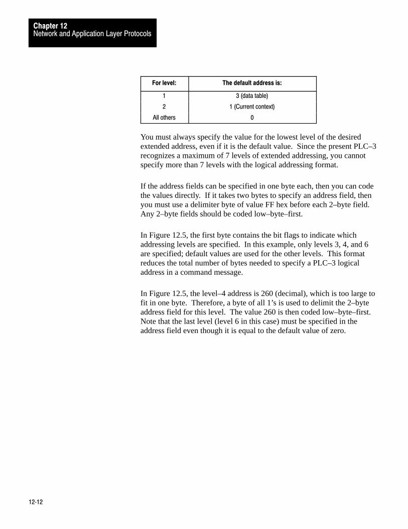
Network and Application Layer ProtocolsChapter 12
12�12
For level: The default address is:
1 3 (data table)
2 1 (Current context)
All others 0
You must always specify the value for the lowest level of the desiredextended address, even if it is the default value. Since the present PLC–3recognizes a maximum of 7 levels of extended addressing, you cannotspecify more than 7 levels with the logical addressing format.
If the address fields can be specified in one byte each, then you can codethe values directly. If it takes two bytes to specify an address field, thenyou must use a delimiter byte of value FF hex before each 2–byte field.Any 2–byte fields should be coded low–byte–first.
In Figure 12.5, the first byte contains the bit flags to indicate whichaddressing levels are specified. In this example, only levels 3, 4, and 6are specified; default values are used for the other levels. This formatreduces the total number of bytes needed to specify a PLC–3 logicaladdress in a command message.
In Figure 12.5, the level–4 address is 260 (decimal), which is too large tofit in one byte. Therefore, a byte of all 1’s is used to delimit the 2–byteaddress field for this level. The value 260 is then coded low–byte–first.Note that the last level (level 6 in this case) must be specified in theaddress field even though it is equal to the default value of zero.

Network and Application Layer ProtocolsChapter 12
12�13
Figure 12.5Example of PLC-3 Logical Addressing Format
6 5 4 3 2 1
0 0 1 1
10066–I
1 0 0 0
0 0 0 00 0 1 0
1 1 1 11 1 1 1
0 0 0 10 0 0 0
0 0 0 00 0 0 1
0 0 0 00 0 0 0
PLC–3 Extended Address
Data Table Area = Level 1Context = Level 2Section = Level 3
File = Level 4
Offset = Level 5
Word = Level 6
Logical Addressing Format
Always zero
Byte 1
Byte 2
Byte 3
Byte 4
Byte 5
Byte 6
Level 1 (Default = 3 for date table)Level 2 (Default = 1 for current context)
Level 3 (Value = 2)Level 4 (Default = 0)
Level 4 (Value = 260)
Level 5 (Default = 1)Level 6 (Value = 0)
Byte 1 –– is the flag byte. In this case it indicates that the addresses for levels 3, 4, and 6 are specified in thebytes that follow. Default values are used for the levels 1, 2, and 5.
Byte 2 –– is the value of the level–3 address.
Byte 3 –– is a delimeter that says the next two bytes are one address.
Byte 4 –– is the low byte of the level–4 address.
Byte 5 –– is the high byte of the level–4 address. Note that bytes 4 and 5 together give a value of 260 for thelevel–4 address.
Byte 6 –– is the value of the level–6 address. Even though it is the default value, it must be specified becauseit is the last level in the desired extended address.
E3 . 1 . 2 . 260 . 0 . 0
Flag bit for level:

Network and Application Layer ProtocolsChapter 12
12�14
The symbolic addressing format applies to PLC–3 type commands(Table 12.A, appendix A) transmitted to the 1775–KA module. You canuse this addressing format whenever you have defined a system symbol torepresent a symbolic address at the PLC–3 station that is to receive thecommand message. Figure 12.6 shows this format for PLC–3 symbolicaddresses. Always enter zeros for the first and last bytes of the symbolicaddress field. Between these zero delimiter bytes, enter the ASCII codesfor the 1 to 8 characters of the symbol name. If the symbol name is morethan 8 characters long, enter only the first 8 characters.
Figure 12.6Format for PLC-3 Symbolic Address
~ ~~~ Etc.
0 (zero)
First character
Second character
Eigth Character
0 (Zero)10067-I
The physical addressing format applies only to PLC–3 physical read andphysical write commands. Physical word addresses run in sequence,starting with 0 (zero) for the first word of PLC–3 memory. Physicaladdresses occupy 2 words (4 bytes), in the following bit format:
A24 A23 A22 A21 A20 A19 A18 A17
0 0 0 0 0 0 0 0
A8 A7 A6 A5 A4 A3 A2 A1
A16 A15 A14 A13 A12 A11 A10 A9
First byte
Second byte
Third byte
Fourth byte

Network and Application Layer ProtocolsChapter 12
12�15
In this format, A1 through A24 represents the 1 to 24 bits of the physicaladdress. For example, to address a command message to physical wordaddress 12,200 decimal (002FA8 hex) you would use the following binarycode in the address field:
0 0 0 0 0 0 0 0
0 0 0 0 0 0 0 0
1 0 1 0 1 0 0 0
0 0 1 0 1 1 1 1
First byte
Second byte
Third byte
Fourth byte
(value 00 hex)
(always 00 hex)
(value A8 hex)
(value 2F hex)
Packet Offset
A single message packet cannot transmit more than 244 bytes of userdata. To allow for data transfers of more than 244 bytes, the 1775–KAmodule automatically transmits as many packets as necessary to completethe message. Thus, a message may consist of several packets strungtogether.
The packet offset is the difference (in 2 byte words) between the startingaddress for the current packet and the starting address for the first packetin the message. The packet offset for the first packet in the message isalways 0 (zero). Thus, adding the packet offset to the address fieldspecified in the message gives the destination address where the currentpacket begins in the destination station.

Appendix
A
A�1
Message Formats
This appendix presents the detailed message formats for each type ofcommand and reply message that the PLC–3 can send and/ore receive.We discuss the message format in the following order:
Basic Command Set
Protected bit writeProtected writeUnprotected bit writeUnprotected readUnprotected write
PLC–3 Commands
Bit writeWord range readWord range writeFile readFile write
Privileged Commands
Privileged readPrivileged writeShutdown requestDownload requestUpload requestRestart requestDiagnostic counters resetDiagnostic loopDiagnostic readDiagnostic status*Set ENQs*Set NAKs*Set timeout*Set variables
Introduction

Message FormatsAppendix A
A�2
*Use these commands to affect only the RS–232–C port of the 1775–KAmodule.
Important : In the formats shown in this section, CMD and FNC valuesare expressed in hexadecimal notation. All other values are given indecimal form. Network layer fields are shaded in blue; data link layerfields are shaded in grey; application layer fields are not shaded.
Building a Line Monitor
This appendix presents the formats for each of the Data Highwaycommands that the 1775–KA module can send and/or receive. You canbuild a line monitor that allows you to see these commands as they aresent or received by the 1775–KA module. This can be useful duringinstallation or when you are troubleshooting. By viewing thesecommands on a line monitor, you can verify the types of messages the1775–KA is sending or receiving and the data that is contained in themessages.
We do not recommend building a line monitor for Data Highwaycommunication. Messages on the Data Highway use a different protocol.But you can monitor communication to the RS–232–C link. To do this,you must create a cable like the one shown in Figure A.1. This cable linksthe 1775–KA module, an RS–232–C device, and a 1770–T4 IndustrialTerminal (Figure A.2). The cable you build connects the receiving data,transmit data, and ground in the RS–232–C link to the receive data andground of the Industrial Terminal. A switch on the cable allows you tochoose the monitor either messages received or messages sent by the1775–KA module.

Message FormatsAppendix A
A�3
Figure A.1Cabling for a RS-232-C Line Monitor
1
2
3
4
5
6
7
8
20
25
25 Pin, FemaleRS-232-C Connector
25 Pin, MaleRS-232-C Connector25 Pin, Male
RS-232-C Connectorof 1775-KA
1775-KA
Toggle SwitchConnections
Channel BIndustrial Terminal(Cat. No. 1770-T4)
To RS-232-C Device
2 = Transmit Data3 = Receive Data7 = Ground
18 = Received Data Return25 = Transmitted Data Return
= Connect these lines accordingto the specifications for yourmodem or RS-232-C device.
3 7 18 25
10069-I

Message FormatsAppendix A
A�4
Figure A.2A RS-232-C Link Configuration that includes a line monitor
10069-I
1775�KAPLC�3 CommunicationAdapter Module
Toggle Switch
Industrial Terminal System(Cat. No. 1770�T4)
Channel B
User�supplied 25 PinMale Connector withStraight Hood(Cat. No. 1770�XXP)
RS�232�Device
25 Pin, FemaleRS�232�C Connector
25 Pin, MaleRS�232�C Connector
25 Pin, MaleRS�232�C Connector
To program the industrial terminal to act as a line monitor, complete thefollowing steps:
1. Attach the 1770–KDA programming keyboard to the industrialterminal.
2. Press SHIFT MODE and type 2 to select the alphanumeric mode.
In the steps that follow, you type a letter key repeatedly until the selectionyou want appears on screen.
3. Type A to select the baud rate you are currently using on the line.
4. Type B to select no parity.
5. Type C to select 1 stop bit.
6. Type E to select cursor on.
7. Type F to select full–duplex.

Message FormatsAppendix A
A�5
Table A.AASCII Codes and Their Numerical Values
Hex Binary ASCII Display[1] Hex Binary ASCII Display [1]
00 0000000 NUL NU 2A 0101010 * (none)
01 0000001 SOH SH 2B 0101011 +
02 0000010 STX SX 2C 0101100 '
03 0000011 ETX EX 2D 0101101 -
04 0000100 EOT ET 2E 0101110 .
05 0000101 ENQ EQ 2F 0101111 /
06 0000110 ACK AK 30 0110000 0
07 0000111 BEL BL 31 0110001 1
08 0001000 BS BS 32 0110010 2
09 0001001 HT HT 33 0110011 3
0A 0001010 LF LF 34 0110100 4
0B 0001011 VT VT 35 0110101 5
0C 0001000 FF FF 36 0110110 6
0D 0001101 CR CR 37 0110111 7
0E 0001110 SO SO 38 0111000 8
0F 0001111 SI SI 39 0111001 9
10 0010000 DLE DL 3A 0111010 :
11 0010001 DC1 D1 3B 0111011 ;
12 0010010 DC2 D2 3C 0111100 <
13 0010011 DC3 D3 3D 0111101 =
14 0010100 DC4 D4 3E 0111110 >
15 0010101 NAK NK 3F 0111111 ?
16 0010110 SYN SY 40 100000 @
17 0010111 ETB EB 41 100001 A
18 0011000 CAN CN 42 1000010 B
19 0011001 EM EM 43 1000011 C
1A 0011010 SUB SB 44 1000100 D
1B 0011011 ESC EC 45 1000101 E
1C 0011100 FS FS 46 1000110 F
1D 0011101 GS GS 47 1000111 G
1E 0011110 RS RS 48 1001000 H
1F 0011111 US US 49 1001001 I
20 0100000 SP (none) 4A 1001010 J
21 0100001 ! (none) 4B 1001011 K
22 0100010 � (none) 4C 1001100 L

Message FormatsAppendix A
A�6
23 0100011 # (none) 4D 1001101 M (none)
24 0100100 $ (none) 4E 1001110 N (none)
25 0100101 % (none) 4F 1001111 O (none)
26 0100110 & (none) 50 1010000 P (none)
27 0100111 ' (none) 51 1010001 Q (none)
28 0101000 ( (none) 52 1010010 R (none)
29 0101001 ) (none) 53 1010011 S (none)
54 1010100 T (none)
[1] Will be dislayed when Control Code Display option is set on.
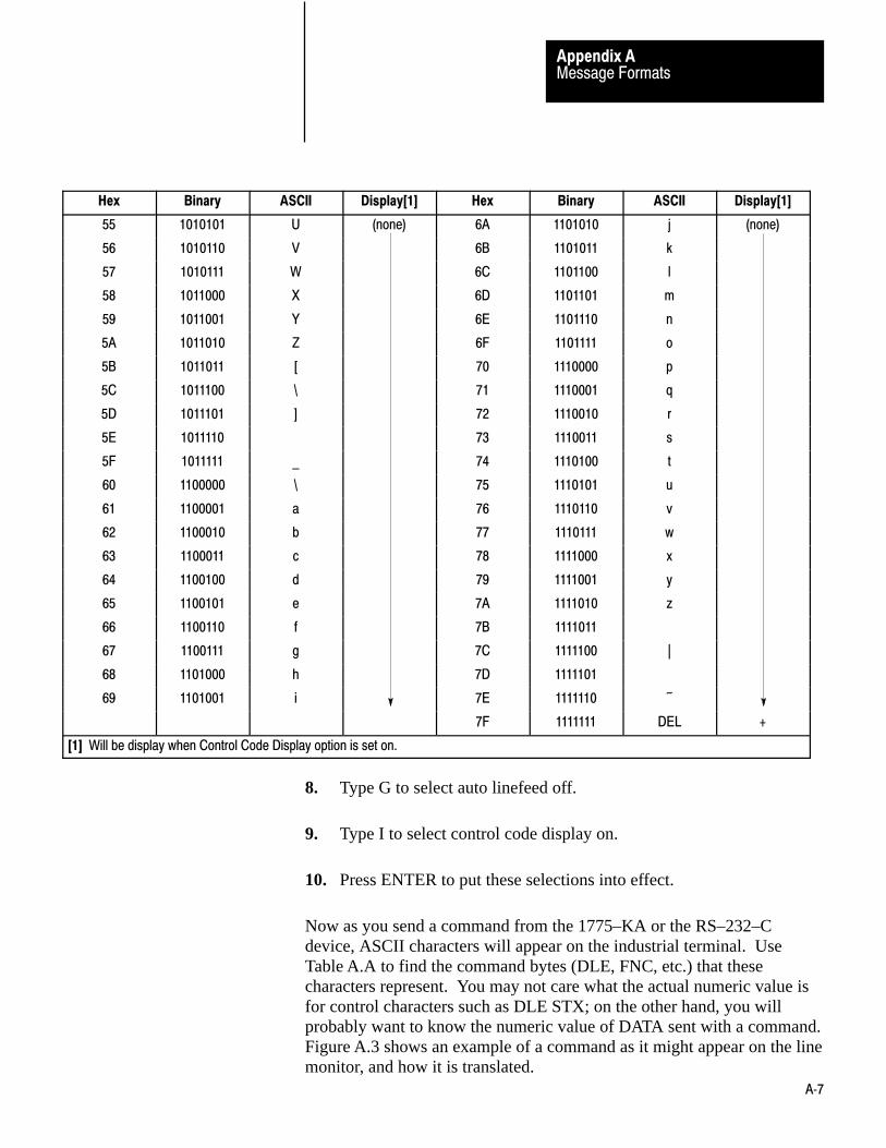
Message FormatsAppendix A
A�7
Hex Binary ASCII Display[1] Hex Binary ASCII Display[1]
55 1010101 U (none) 6A 1101010 j (none)
56 1010110 V 6B 1101011 k
57 1010111 W 6C 1101100 l
58 1011000 X 6D 1101101 m
59 1011001 Y 6E 1101110 n
5A 1011010 Z 6F 1101111 o
5B 1011011 [ 70 1110000 p
5C 1011100 \ 71 1110001 q
5D 1011101 ] 72 1110010 r
5E 1011110 73 1110011 s
5F 1011111 _ 74 1110100 t
60 1100000 \ 75 1110101 u
61 1100001 a 76 1110110 v
62 1100010 b 77 1110111 w
63 1100011 c 78 1111000 x
64 1100100 d 79 1111001 y
65 1100101 e 7A 1111010 z
66 1100110 f 7B 1111011
67 1100111 g 7C 1111100 |
68 1101000 h 7D 1111101
69 1101001 i 7E 1111110 ~
7F 1111111 DEL +
[1] Will be display when Control Code Display option is set on.
8. Type G to select auto linefeed off.
9. Type I to select control code display on.
10. Press ENTER to put these selections into effect.
Now as you send a command from the 1775–KA or the RS–232–Cdevice, ASCII characters will appear on the industrial terminal. UseTable A.A to find the command bytes (DLE, FNC, etc.) that thesecharacters represent. You may not care what the actual numeric value isfor control characters such as DLE STX; on the other hand, you willprobably want to know the numeric value of DATA sent with a command.Figure A.3 shows an example of a command as it might appear on the linemonitor, and how it is translated.

Message FormatsAppendix A
A�8
Figure A.3Typical monitor display and how it is interpreted
S B 8NN AK
NU U EX
DL
EX
DL
AKX S UL
D >
{ { { { { { { { { { { {
DLE STX DST SRC CMD STS TNS FNC DLE ETX BCC DLE ACK
Monitoring a diagnosticc status command and reply acknowledgement.
Line monitor displays:
Examining the ASCII table shows that for the above message:
CMD = 6STS = 0FNC = 3
10070-I
∼
The basic command set includes those commands that can generally beexecuted by any PC station on the communication link, regardless of thetype of PC controller at the station. In some cases, switch settings on thestation interface module can disable execution of a particular type ofcommand at that station. For more details, refer to the user’s manual forthe station interface module.
The basic commands are:
protected bit write protected write unprotected bit write unprotected read unprotected write
Protected Bit Write
Use this command to set or reset individual bits within limited areas of thePC data table memory. Your access can be limited by memory accessrungs in the communication zone of the PC’s ladder diagram program.
The data field in this packet consists of 4–byte blocks, each of whichcontains a 16–bit address field, a set mask, and a reset mask. Use theADDR field to specify the address of the byte to be modified in the PC
Basic Command Set

Message FormatsAppendix A
A�9
data table memory. Put the low byte (lest significant bits) of the PCaddress value into the first byte of the ADDr field.
Use the SET mask to specify which bits to set to 1 in the addressed PCbyte. A1 in a bit position of the SET mask means to set the correspondingbit in the addressed PC byte to 1; a 0 in a bit position of the SET maskmeans to leave the corresponding bit in the PC byte unchanged.
Use the RESET mask to specify which bits to reset to 0 in the addressedPC byte. A1 in a bit position of the RESET mask means to reset thecorresponding bit in the addressed PC byte to 0; a 0 in a bit position of thereset mask means to leave the corresponding bit in the PC byteunchanged.
Note that the interface module at the receiving PC station executes thiscommand by first making a copy of the addressed PC byte. It then sets orresets the appropriate bits and writes the byte back into PC memory. Atthe same time, the PC processor can be changing the states of the originalbits in memory. Because of this, some data bits may unintentionally beoverwritten.
Command Format:
DLE SRC C 0
TNSTNS ADDR SET RESETUp to 61 masks of this form
STX DLE ETX BCCSMD2
TS
Reply Format:
DST SRC C
S TNSMD T S TNS42
DLE STX DLE ETX BCC
Protected Write
Use this command to write words of data into limited areas of the PC datatable memory. Your access can be limited by memory access rungs in thecommunication zone of the PC’s ladder diagram program.

Message FormatsAppendix A
A�10
Command Format:
DLE SRC C 0
S TNSMD0
TS TNS ADDRSTX DLE ETX BCCDATA - Max of 243 bytes
Reply Format:
DST SRC C
S TNSMD T S TNS40
DLE STX DLE ETX BCC
Unprotected Bit Write
Use this command to set or reset individual bits in any area of PC datatable memory. The data field in this packet consists of 4–byte blocks,each of which contains a 16–bit address field, a set mask, and a resetmask. Use the ADDR field to specify the address of the byte to bemodified in the PC data table memory. Put the low byte (least significantbits) of the PC address value into the first byte of the ADDR field.
Use the SET mask to specify which bits to set to 1 in the addressed PCbyte. A1 in a bit position of the SET mask means to set the correspondingbit in the addressed PC byte to 1; a 0 in a bit position of the SET maskmeans to leave the corresponding bit in the PC byte unchanged.
Use the RESET mask to specify which bits to reset to 0 in the addressedPC byte. A 1 in a bit position of the RESET mask means to reset thecorresponding bit in the addressed PC byte to 0; a 0 in a bit position of theRESET mask means to leave the corresponding bit in the PC byteunchanged.
Note that the interface module at the receiving PC station executes thiscommand by first making a copy of the addressed PC byte. It then sets orresets the appropriate bits and writes the byte back into PC memory. Atthe same time, the PC processor can be changing the states of the originalbits in memory. Because of this, some data bits may unintentionally beoverwritten.
Command Format:

Message FormatsAppendix A
A�11
DLE SRC C 0
S TNSMD5
TS TNS ADDR SET RESETUp to 61 masks of this form
STX DLE ETX BCC
Reply Format:
DST SRC C
S TNSMD T S TNS45
DLE STX DLE ETX BCC

Message FormatsAppendix A
A�12
Unprotected Read
Use this command to read words of data from any area of PC data tablememory. Use the SIZE field to specify the number of bytes to be read.To specify a number of PC words, SIZE should be an even value becausePC words are two bytes long.
Command Format:
DLE SRC C 0
S TNSMD1
TS TNSSTX DLE ETX BCCADDR SIZE
Reply Format:
DLE SRC C 4
S TNSMD1
TS TNS ADDRSTX DLE ETX BCCDATA - Max of 244 bytes
Unprotected Write
Use this command to write words of data into any area of PC data tablememory.
Command Format:
DLE SRC C 0
S TNSMD8
TS TNS ADDRSTX DLE ETX BCCDATA - Max of 242 bytes
Reply Format:
DLE SRC C 0
S TNSMD1
TS TNSSTX DLE ETX BCC

Message FormatsAppendix A
A�13
PLC–3 stations can receive any of the commands in the basic commandset and execute them within a specified file in the PLC–3 memory. Theycan also execute the following commands, which apply only to PLC–3controllers:
bit write word range read word range write file read file write
Only a computer can send privileged commands. Their primary use is foruploading and downloading PLC–3 memory.
Only a computer or another PLC–3 station can initiate the non–privilegedPLC–3 commands listed above. Their primary use is for transferring databetween two PLC–3 files. Those files may be located in the same PLC–3processor or in two different PLC–3’s
Bit Write
Use this bit write command to modify the bits at the address specified byeither a word symbol, a file symbol plus a word offset, or a logicaladdress. This write command can write a block of data. This addressmust point to a word within a file. The function code is 2. Unlike theunprotected and protected bit writes in the basic command set, thiscommand can be used to change the bits in a single word only.
Command Format:
A. Word symbol address
DLE SRC C 0
S TNSMDF
TS TNSSTX FNC 0002
ASCII sumbol(8 characters max)
DLE ETX BCC00 W/F00
SET RESETMask Mask
PLC-3 Commands

Message FormatsAppendix A
A�14
B. File symbol address plus word offset
DLE SRC C 0
S TNSMDF
TS TNSSTX FNC 0002
ASCII sumbol(8 characters max)
DLE ETX BCC00 W/F01
SET RESETMask Mask
C. Logical address
DLE SRC C 0
S TNSMDF
TS TNSSTX FNC02
PLC-3 logical address(2-51 bytes)
DLE ETX BCCSET RESETMask Mask
Reply Format:
This the same as the reply packet format for all bit writes
A. Format when successful execution
DLE SRC C 4F
S TNSMD TS TNSSTX DLE ETX BCCDST
B. Format when reporting an error
DLE SRCSTX DST C 4F
S TNSMD TS TNS DLE ETX BCCETXSTS TNS
Where the extended status byte is optional
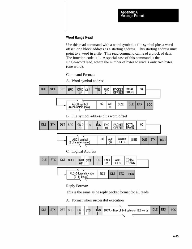
Message FormatsAppendix A
A�15
Word Range Read
Use this read command with a word symbol, a file symbol plus a wordoffset, or a block address as a starting address. This starting address mustpoint to a word in a file. This read command can read a block of data.The function code is 1. A special case of this command is thesingle–word read, where the number of bytes to read is only two bytes(one word).
Command Format:
A. Word symbol address
DLE SRC C 0
S TNSMDF
TS TNSSTX FNC PACKET01
ASCII symbol(8 characters max)
DLE ETX BCC00 W/F00
SIZE
OFFSETTOTALTRANS
00DST
B. File symbol address plus word offset
DLE SRC C 0
S TNSMDF
TS TNSSTX FNC PACKET01
ASCII symbol(8 characters max)
DLE ETX BCC00 W/F00
SIZE
OFFSETTOTALTRANS
00DST
WORDOFFSET
C. Logical Address
DLE SRC C 0
S TNSMDF
TS TNSSTX FNC PACKET01
PLC-3 logical symbol(2-51 bytes)
DLE ETX BCCSIZE
OFFSETTOTALTRANS
DST
Reply Format:
This is the same as he reply packet format for all reads.
A. Format when successful execution
DLE C
S TNSMD TS TNSSTX DLE ETX BCCDATA - Max of 244 bytes or 122 wordsDST SRC 4F

Message FormatsAppendix A
A�16
B. Format when reporting an error
DLE SRCSTX DST C 4F
S TNSMD TS TNS DLE ETX BCCETXSTS
Where the extended status byte is optional.
Word Range Write
Use this write command with a word symbol, a file symbol plus a wordoffset, or a logical address as a starting address. This starting addressmust point to a word in a file. This write command can write a block ofdata. The function code is 0 (zero). A special case of this command is thesingle word write, where the data field is only one word long.
Command Format:
A. Word symbol address
DLE SRC C 0
S TNSMDF
TS TNSSTX FNC PACKET00
ASCII symbol(8 characters max)
DLE ETX BCC00 W/F00
OFFSETTOTALTRANS
00DST
ASCII s(8 characters max)
DATA - Max of 228 bytes or 114 words
B. File symbol address plus word offset
DLE SRC C 0
S TNSMDF
TS TNSSTX FNC PACKET00
ASCII symbol(8 characters max)
DLE ETX BCC00
OFFSETTOTALTRANS
00DST
ASCII(8 characters max)
DATA - Max of 226 bytes or 113 words
W/F01
WORDOFFSET
C. Logical address
DLE SRC C 0
S TNSMDF
TS TNSSTX FNC PACKET00
DLE ETX BCC
OFFSETTOTALTRANS
DST
DATA - Max length is 239 bytes minusPLC-3 logical address(2-51 bytes)
the length of the PLC-3 logical address(must be an even number of bytes)

Message FormatsAppendix A
A�17
Reply Format:
This is the same as the reply packet format for all writes.
A. Format when successful execution.
DLE SRCSTX DST C 4F
S TNSMD TS TNS DLE ETX BCC
B. Format when reporting an error
DLE SRCSTX DST C 4F
S TNSMD TS TNS DLE ETX BCCETXSTS
Where the extended status byte is optional.
File Read
Use this read command with either a file symbol or a block address for astarting address. This starting address points to a file of words. This readcommand reads a block of data. You must read the entire file. The filesize must equal the exact size of the file or an error will be returned. Thefunction code is 4.
Command Format:
A. File symbol address
DLE SRC C 0
S TNSMDF
TS TNSSTX FNC PACKET04
DLE ETX BCC00 SIZE
OFFSETTOTALTRANS
00DST
00 ASCII symbol(8 characters max)
B. Logical address
DLE SRC C 0
S TNSMDF
TS TNSSTX FNC PACKET04
DLE ETX BCCSIZE
OFFSETTOTALTRANS
00DST
PLC-3 logical address(2-51 bytes)

Message FormatsAppendix A
A�18
Reply Format:
This is the same as the reply packet format for all reads.
A. Format when the command was successfully executed
DLE C
S TNSMD TS TNSSTX DLE ETX BCCDATA - Max of 244 bytes or 122 wordsDST SRC 4F
B. Format when reporting an error
DLE SRCSTX DST C 4F
S TNSMD TS TNS DLE ETX BCCETXSTS
Where the extended status byte is optional.

Message FormatsAppendix A
A�19
File Write
Use this write command with either a file symbol or a block address as astarting address. This starting address points to a file of words. Thiswrite command can write a block of data. You must read the entire file.The file size must equal the exact size of the file or an error will bereturned. The function code is 3.
Command Packet Format:
A. File symbol address
DLE SRC C 0
S TNSMDF
TS TNSSTX FNC PACKET03 OFFSET
TOTALTRANS
00DST
ASCII symbol(8 characters max)
00ASCII s(8 characters max)
DLE ETX BCCDATA - Max of 244 bytes or 114 words
B. Logical address
DLE SRC C 0
S TNSMDF
TS TNSSTX FNC PACKET03
DLE ETX BCC
OFFSETTOTALTRANS
DST
DATA - Max length is 239 bytes minusPLC-3 logical address(2-51 bytes)
the length of the PLC-3 logical address(must be an even number of bytes)
Reply Format:
This is the same as the reply packet format for all writes.
A. Format when the command was successfully executed
DLE SRCSTX DST C 4F
S TNSMD TS TNS DLE ETX BCC
B. Format when reporting an error
DLE SRCSTX DST C 4F
S TNSMD TS TNS DLE ETX BCCETXSTS

Message FormatsAppendix A
A�20
Where the extended status byte is optional.
A PLC–3 receives privileged commands from an RS–232–C device (suchas a computer); the PLC–3 does not send these commands. Theprivileged commands are:
privileged read download request privileged write upload request diagnostic counters reset restart request diagnostic loop set ENQs diagnostic read set NAKs diagnostic status set timeout
Privileged Read
Use this read command with a PLC–3 physical address as a startingaddress. You use this command to upload from a PLC–3 to a computer.The destination 1775–KA module will accept this command only after thesource station has successfully transmitted a shutdown request. Thefunction code for this command is 9.
Command Format:
DLE SRC C 0
S TNSMDF
TS TNSSTX FNC09
SIZEDST DLE ETX BCCPLC-3physical address
Reply Format:
TDATA–Max of 238 bytes or 119 words DLE ETX BCChis is the sameas the reply packet format for all reads.
A. Format when the command was successfully executed
DLE C
S TNSMD TS TNSSTX DLE ETX BCCDATA - Max of 244 bytes or 122 wordsDST SRC 4F
B. Format when reporting an error
DLE SRCSTX DST C 4F
S TNSMD TS TNS DLE ETX BCCETXSTS
Where the extended status byte is optional.
Privileged Commands

Message FormatsAppendix A
A�21
Privileged Write
Use this write command with a PLC–3 physical address as a startingaddress. You use this command to download to a PLC–3 from acomputer. The destination 1775– KA module will accept this commandonly after the source station has successfully transmitted a shutdownrequest. The function code for this command is 8.
Command Format:
DLE SRC C 0
S TNSMDF
TS TNSSTX FNC08
DST
DLE ETX BCCDATA - Max of 238 bytes or 119 words
PLC-3physical address
Reply Format:
This is the same as the reply packet format for all writes.
A. Format when the command was successfully executed
DLE SRCSTX DST C 4F
S TNSMD TS TNS DLE ETX BCC
B. Format when reporting an error
ETXSTS
DLE SRCSTX DST C 4F
S TNSMD TS TNS DLE ETX BCC
Where the extended status byte is optional.
From a computer you use this command to ask the 1775–KA module toinitiate either a PLC–3 shutdown (if the computer has downloadprivileges) or a freeze on file allocations (if the computer has uploadprivileges). This command halts program and I/O scanning. You cannotissue this command until you have successfully transmitted an upload ordownload request to the 1775–KA module. This command has a functioncode of 7.
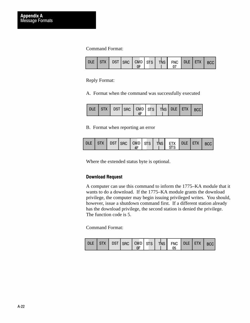
Message FormatsAppendix A
A�22
Command Format:
FNCDLE SRCSTX DST C 0F
S TNSMD TS TNS DLE ETX BCC07
Reply Format:
A. Format when the command was successfully executed
DLE SRCSTX DST C 4F
S TNSMD TS TNS DLE ETX BCC
B. Format when reporting an error
ETXSTS
DLE SRCSTX DST C 4F
S TNSMD TS TNS DLE ETX BCC
Where the extended status byte is optional.
Download Request
A computer can use this command to inform the 1775–KA module that itwants to do a download. If the 1775–KA module grants the downloadprivilege, the computer may begin issuing privileged writes. You should,however, issue a shutdown command first. If a different station alreadyhas the download privilege, the second station is denied the privilege.The function code is 5.
Command Format:
FNCDLE SRCSTX DST C 0F
S TNSMD TS TNS DLE ETX BCC05
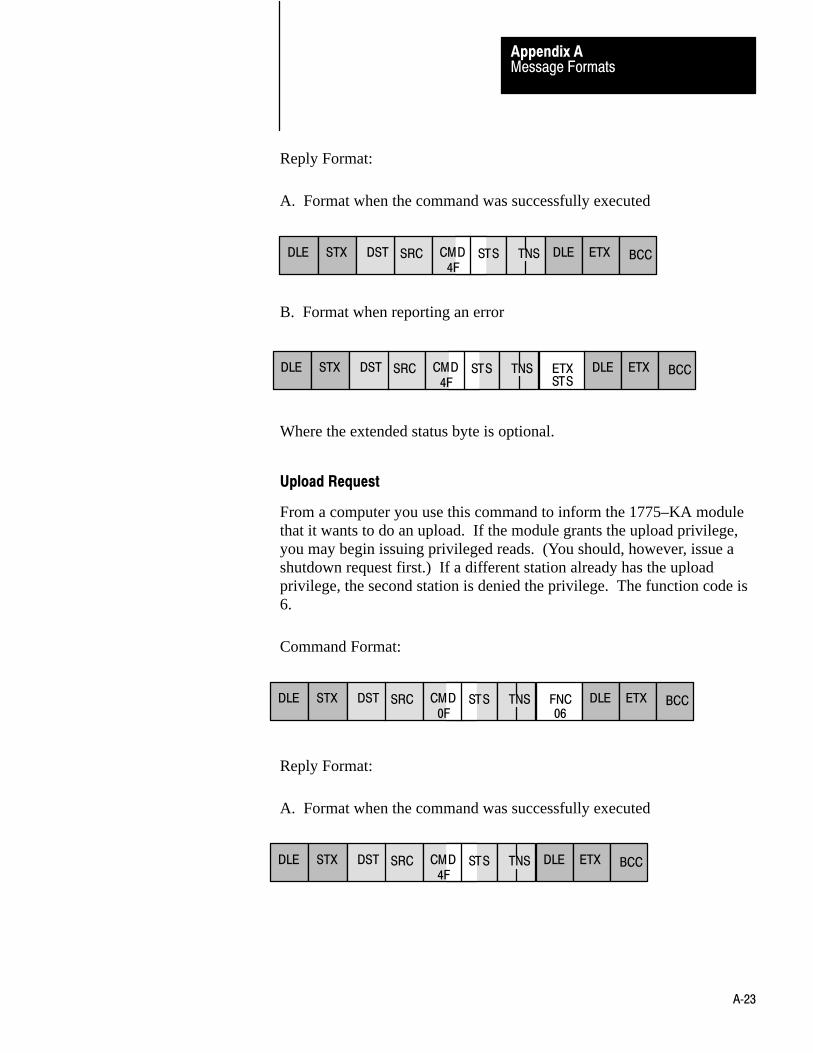
Message FormatsAppendix A
A�23
Reply Format:
A. Format when the command was successfully executed
DLE SRCSTX DST C 4F
S TNSMD TS TNS DLE ETX BCC
B. Format when reporting an error
ETXSTS
DLE SRCSTX DST C 4F
S TNSMD TS TNS DLE ETX BCC
Where the extended status byte is optional.
Upload Request
From a computer you use this command to inform the 1775–KA modulethat it wants to do an upload. If the module grants the upload privilege,you may begin issuing privileged reads. (You should, however, issue ashutdown request first.) If a different station already has the uploadprivilege, the second station is denied the privilege. The function code is6.
Command Format:
FNCDLE SRCSTX DST C 0F
S TNSMD TS TNS DLE ETX BCC06
Reply Format:
A. Format when the command was successfully executed
DLE SRCSTX DST C 4F
S TNSMD TS TNS DLE ETX BCC
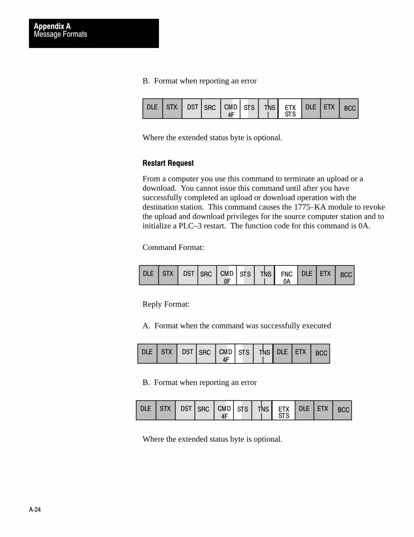
Message FormatsAppendix A
A�24
B. Format when reporting an error
ETXSTS
DLE SRCSTX DST C 4F
S TNSMD TS TNS DLE ETX BCC
Where the extended status byte is optional.
Restart Request
From a computer you use this command to terminate an upload or adownload. You cannot issue this command until after you havesuccessfully completed an upload or download operation with thedestination station. This command causes the 1775–KA module to revokethe upload and download privileges for the source computer station and toinitialize a PLC–3 restart. The function code for this command is 0A.
Command Format:
FNCDLE SRCSTX DST C 0F
S TNSMD TS TNS DLE ETX BCC0A
Reply Format:
A. Format when the command was successfully executed
DLE SRCSTX DST C 4F
S TNSMD TS TNS DLE ETX BCC
B. Format when reporting an error
ETXSTS
DLE SRCSTX DST C 4F
S TNSMD TS TNS DLE ETX BCC
Where the extended status byte is optional.

Message FormatsAppendix A
A�25
Diagnostic Counters Reset
Use this command to reset to zero all the diagnostic timers and counters inthe station interface module. The diagnostic status command gives thestarting address for this block of counters and timers.
Command Format:
FNCDLE SRCSTX DST C 06
S TNSMD TS TNS DLE ETX BCC07
DATA
Reply Format:
DLE SRCSTX DST C 46
S TNSMD TS TNS DLE ETX BCC
Diagnostic Loop
You can use this command to check the integrity of transmissions over thecommunication link. The command message transmits up to 243 bytes ofdata to a station interface module. The receiving module should reply tothis command by transmitting the same data back to the originatingstation.
Command Format:
DLE C
S TNSMD TS TNSSTX DLE ETX BCCDATA - Max of 243 bytesDST SRC 06
FNC00
Reply Format:
DLE C
S TNSMD TS TNSSTX DLE ETX BCCDATA - Max of 244 bytesDST SRC 46

Message FormatsAppendix A
A�26
Diagnostic Read
You use this command to read up to 244 bytes of data from the PROM orRAM of the station interface module. You can use it to read the module’sdiagnostic timers and counters. Use the diagnostic status command toobtain the starting address of the diagnostic counters.
Command Format:
FNCDLE SRCSTX DST C 06
S TNSMD TS TNS DLE ETX BCC01
SIZEADDR
Reply Format:
DLE C
S TNSMD TS TNSSTX DLE ETX BCCDATA - Max of 244 bytesDST SRC 46
Diagnostic Status
You use this command to read a block of status information from thestation interface module. The reply to this command contains the statusinformation in its DATA field.
Command Format:
FNCDLE SRCSTX DST C 06
S TNSMD TS TNS DLE ETX BCC03
Reply Format:
DLE C
S TNSMD TS TNSSTX DLE ETX BCCDATA - Max of 244 bytesDST SRC 46
The status information varies with the type of station interface module.Table A.B describes this status DATA for 1775–KA modules.
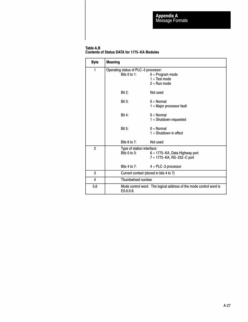
Message FormatsAppendix A
A�27
Table A.BContents of Status DATA for 1775-KA Modules
Byte Meaning
1 Operating status of PLC-3 processor:Bits 0 to 1: 0 = Program mode
1 = Test mode2 = Run mode
Bit 2: Not used
Bit 3: 0 = Normal1 = Major processor fault
Bit 4: 0 = Normal1 = Shutdown requested
Bit 5: 0 = Normal1 = Shutdown in effect
Bits 6 to 7: Not used
2 Type of station interface:Bits 0 to 3: 6 = 1775-KA, Data Highway port
7 = 1775-KA, RS-232-C port
Bits 4 to 7: 4 = PLC-3 processor
3 Current context (stored in bits 4 to 7)
4 Thumbwheel number
5,6 Mode control word. The logical address of the mode control word is E0.0.0.8.

Message FormatsAppendix A
A�28
Byte Meaning
7,8 Starting byte address of the diagnostic counters and timers. There is a separate block of diagnostic timers and counters for the data highway port and the RS-232-C port. The address given here is the one for the port that received the diagnostic status command.
9 Series and revision number of the 1775-KA module:Bits 0 to 4: 0 = Revision A
1 = Revision Betc.
Bits 5 to 7: 0 = Series A1 = Series Betc.
10 Not used
11to14
The physical address of the unused word of PLC-3 system memory.This is the physical address corresponding to the logical addressE60.0.0.0.
15t
18
The total number of words in PLC-3 system memory (both used andunused). This is the physical word address corresponding to thelogical address E63.0.0.0.
Set ENQs
Use this command to set the maximum number of ENQs that the stationinterface module will issue per message transmission. Put the number inthe DATA field. The default setting for the KE/KF module is 10 ENQsper transmission.
Command Format:
FNCDLE SRCSTX DST C 06
S TNSMD TS TNS DLE ETX BCC06
DATA
Reply Format:
DLE SRCSTX DST C 46
S TNSMD TS TNS DLE ETX BCC

Message FormatsAppendix A
A�29
Set NAKs
Use this command to set the maximum number of NAKs that the stationinterface module will accept per message transmission. Put the number inthe DATA field. The default setting for the KE/KF module is 3 NAKs pertransmission.
Command Format:
FNCDLE SRCSTX DST C 06
S TNSMD TS TNS DLE ETX BCC05
DATA
Reply Format:
DLE SRCSTX DST C 46
S TNSMD TS TNS DLE ETX BCC
Set Timeout
Use this command to set the maximum amount of time that the stationinterface module will wait for an acknowledgment to its messagetransmission. The setting is expressed as the number of cycles of aninternal clock, where 40 cycles equals 1 second. Put the number ofdesired cycles in the DATA field. The default setting for the KE/KFmodule is 128 cycles, or about 3 seconds.
Command Format:
FNCDLE SRCSTX DST C 06
S TNSMD TS TNS DLE ETX BCC04
DATA
Reply Format:
DLE SRCSTX DST C 46
S TNSMD TS TNS DLE ETX BCC

Message FormatsAppendix A
A�30
Set Variables
Use this command to set the timeout and maximum NAKs, and ENQs allat once. Put the timeout in the first byte of the DATA field, the NAKsetting in the second byte, and the ENQ setting in the third byte. If you donot specify a data value for any one the variables in this command, thatvariable is automatically reset to zero.
Command Format:
FNCDLE SRCSTX DST C 06
S TNSMD TS TNS DLE ETX BCC02
DATA - 3 bytes
Reply Format:
DLE SRCSTX DST C 46
S TNSMD TS TNS DLE ETX BCC

Appendix
B
B�1
Error Codes
This appendix describes the error codes that the 1775–KA module willreport. Errors are of three types:
local reply remote
The 1775–KA module generates local errors while trying to execute oneof its own message procedures. The module stores local error codesunder the user symbol ERROR. Possible local errors are listed in sectiontitled Local and Reply Error Codes.
The 1775–KA module generates reply errors while trying to respond to acommand message received from a remote Data Highway station. The1775–KA module inserts the reply error code in the STS or EXT STSbytes (Appendix A) of any reply message packet it transmits to a remotestation. For reply errors, there is a direct correlation between the errorcodes in the STS and EXT STS bytes of reply messages and the errorcodes reported at the remote station. The correlation is as follows:
General
Local Error Codes
Reply Error Codes

Remote Error Codes Received from the1773-KA Module
Appendix B
B�2
These codes are sent by the 1775-KA: This error code is then stored atthe command station (decimal):
STS byte(hexadecimal
EXT STS byte(hexademical):
00 not used no error
10 not used 81
30 not used 83
40 not used 84
50 not used 85
60 not used 86
70 not used 87
F0 1 231
F0 2 232
F0 3 233
F0 4 234
F0 5 235
F0 6 236
F0 7 237
F0 8 238
F0 9 239
F0 10 240
F0 11 241
Note that a value of F0 (hex) in the STS byte indicates that the EXT STSbyte actually contains the error code for the reply message. Currently,only the 1775–KA module is capable of generating and accepting replymessages with error codes reported in this way. In particular, 1771–KAand 1774–KA modules cannot interpret these error codes.
The meaning of each error code depends on the command message thatthe local PLC–3 station receives from a remote station. Section titledLocal and Reply Error Codes describes the error conditions that thevarious commands can generate. The error codes are listed according tothe decimal value that would be stored at the command initiating station.
Remote Error Codes Received from the1773-KA Module
Appendix B
B�3
When a remote station transmits a command, the local 1775–KA modulemight issue a reply message that contains one of the error codes listed insection titled Local and Reply Error Codes. Error codes 81 to 87 appearin the STS byte of the reply message, and codes 231 to 241 appear in theEXT STS byte (Appendix A).
The local PLC–3 station receives remote error codes in a reply to acommand it has sent to a remote station. These error codes are storedunder user symbol ERROR in the local PLC–3 station.
The extended address for the beginning of the error block file is
$E2.5.nn.4.0
where nn is the thumbwheel number of the 1775–KA module. You canaccess this error block by any one of the following means:
displaying it through the front panel of the PLC–3 controller using the data monitor mode of the Industrial Terminal (cat. no.
1770–T4) using the move status (MVS) command in the PLC–3 ladder diagram
program using the I/O Scanner–Message Handling Module (cat. no. 1775–S4B) using the 1775–KA module
The meaning of a particular remote error code will vary, depending on thetype of communication interface module at the remote station. Forexample, if the remote station is a PLC–3 processor with a 1775–KAinterface module, the remote error codes will have the meanings listed insection tilted Local and Reply Error Codes. For the meanings of otherremote error codes, refer to the appropriate user’s manual for thecommunication interface module at the remote station.
Remote Error Codes

Remote Error Codes Received from the1773-KA Module
Appendix B
B�4
Local and Reply Error Code Listing for the PLC–3 Processor
Error Error
Code Type Meaning
32 Local The size of the local file involved in a file
assignment command is greater than 65,535
bytes.
34 local A station number greater than 376 (octal)
was specified for the remote address in an
assignment command.
35 local Attempt to send unprotected command is
invalid.
37 local The per-packet timeout, which can be set
through LIST, ran out before a reply was
received. This means that the remote station
acknowledged (ACK) the command
message, but did not send the reply in the
allotted time. (cf. error 92)
81 reply For diagnostic read commands:
1.A 2-byte ADDR field and a 1-byte SIZE
field are missing after the FNC byte in the
command message.
2.The number of bytes of data requested in
the SIZE field is greater than the
maximum number allowed per reply
packer (244), or SIZE is 0 (zero).
For PLC/PLC-2 read commands:
1.The required 2-byte ADDR field and
1-byte SIZE field are missing in the
command message.
2.The ADDR value is odd (that is, it does
not specify a word address).
3.The value of SIZE is 0 (zero).
4.The value of SIZE is greater than 244.
5.The SIZE value specifies an odd number
of bytes.
For PLC/PLC-2 bit write commands:
Incomplete bit description because the
Local and Reply Error Codes
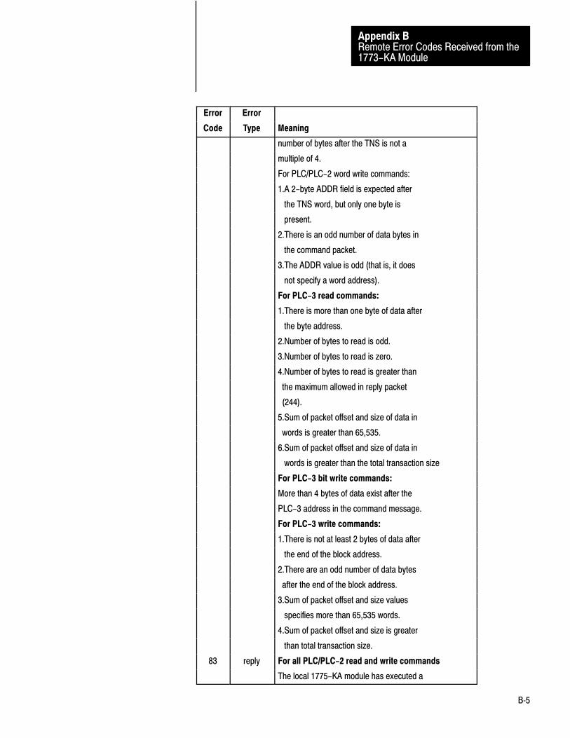
Remote Error Codes Received from the1773-KA Module
Appendix B
B�5
Error Error
Code Type Meaning
number of bytes after the TNS is not a
multiple of 4.
For PLC/PLC-2 word write commands:
1.A 2-byte ADDR field is expected after
the TNS word, but only one byte is
present.
2.There is an odd number of data bytes in
the command packet.
3.The ADDR value is odd (that is, it does
not specify a word address).
For PLC-3 read commands:
1.There is more than one byte of data after
the byte address.
2.Number of bytes to read is odd.
3.Number of bytes to read is zero.
4.Number of bytes to read is greater than
the maximum allowed in reply packet
(244).
5.Sum of packet offset and size of data in
words is greater than 65,535.
6.Sum of packet offset and size of data in
words is greater than the total transaction size
For PLC-3 bit write commands:
More than 4 bytes of data exist after the
PLC-3 address in the command message.
For PLC-3 write commands:
1.There is not at least 2 bytes of data after
the end of the block address.
2.There are an odd number of data bytes
after the end of the block address.
3.Sum of packet offset and size values
specifies more than 65,535 words.
4.Sum of packet offset and size is greater
than total transaction size.
83 reply For all PLC/PLC-2 read and write commands
The local 1775-KA module has executed a

Remote Error Codes Received from the1773-KA Module
Appendix B
B�6
Error Error
Code Type Meaning
shutdown request to the local PLC-3 processor
For all PLC-3 read and write commands:
The local 1775-KA module has executed a
shutdown request.
84 reply For diagnostic status commands:
A backplane error occurred during
determination of the physical address of the
end of the ladder diagram program or of the
end of user memory. In polled mode, the
RS-232- C port has received a NAK, which
caused a system reset.
For all PLC/PLC-2 read and write commands:
Local PLC-3 backplane error (either memory
parity or timeout/disconnect). In polled mode,
the RS-232-C port has received a NAK, which
caused a system shutdown.
For all PLC-3 read and write commands:
Backplane error (memory parity or timeout/
disconnect). In polled mode, the RS-232-C port
has received a NAK, which caused a system reset.
85 reply For diagnostic read commands:
The command is an illegal request to read from the
1775- KA module's backplane window.
For PLC/PLC-2 read commands:
1. PLC-3 file does not exist.
2. PLC-3 file is too small.
3. PLC-3 file is more than 65,535 words long.
For PLC/PLC-2 bit write commands:
1. PLC-3 file does not exist.
2. Destination bits do not exist in PLC-3 file.
3. Length of PLC-3 file is greater than 65,535
words.
For PLC/PLC-2 word write commands:
1.The destination file does not exist in PLC-3
memory.
2.The destination word does not exist in the

Remote Error Codes Received from the1773-KA Module
Appendix B
B�7
Error Error
Code Type Meaning
destination PLC-3 file.
3.The length of the destination file is greater than
65,535 words.
86 reply For PLC/PLC-2 bit write commands:
Keyswitch setting at local PLC-3 processor
prohibits access.
For PLC/PLC-2 word write commands:
Local keyswitch setting prohibits writing into
desired destination file.
For all PLC-3 write commands:
Keyswitch setting disallows access to file.
87 reply For all PLC/PLC-2 read and write commands:
The local PLC-3 processor is in program mode.
There may or may not be a major system fault.
For all PLC-3 read and write commands:
The local PLC-3 processor is in program mode.
There may or may not be a major system fault.
91 Local Handshaking lines on the RS-232-C link are not
connected properly.
92 local The remote station specified does not acknowledge
(ACK) the message.
94 local Local port is disabled through LIST.
112 local 1.Undefined assignment operator in an assignment
statement.
2.Undefined operator in an expression.
114 local Illegal expression syntax.
115 local Illegal unary (prefix) operator in an expression.
117 local Undefined data following a valid address in a
CREATE command, or undefined data following a
valid symbol in a DELETE command.
121 local Symbol undefined. This will occur if a symbol
appears as the source in an assignment command
before it is defined as a symbol. For example, a
statement of the form A = A + 6 will give this error
if user symbol 'A' has not appeared previously.
123 local System symbol must be a symbolic address. This

Remote Error Codes Received from the1773-KA Module
Appendix B
B�8
Error Error
Code Type Meaning
error will occur if a procedure name is used in
place of a symbolic address in an assignment
statement or if the system symbol referenced in an
assignment doesn't exist.
124 local Illegal destination in an assignment command. This
does not necessarily mean that an assignment
command was desired because any command line
that doesn't look like anything else is assumed to
be an assignment command. Lines that will
generate this error include:
5 = 4 + 1
6ASDFGHJ
Whereas the line
WERTYUI
will generate an error 140 (unrecognized
command).
125 local Illegal modifier for the CREATE command. That
is, the command was CREATE/...and the...was
other than LOCAL, GLOBAL, or a legal
abbreviation of one of these.
126 local The CREATE command was specified, but the
symbol did not begin with an '@'.
127 local missing in CREATE system symbol address.
129 local Attempt to delete nonexistent symbol.
140 local Unrecognized or ambiguous command. (cf. error
124)
142 local Illegal data following GOTO command.
143 local Illegal use of label (eg., not in a procedure).
144 local Label not found.
145 local Duplicate label. User symbols must be distinct
from labels.
146 local Too many nested procedures.
147 local Insufficient privilege for the specified operation.
This error can occur when an attempt is made, via
the assignment command, to write into a major
section of memory in which the 1775-KA module

Remote Error Codes Received from the1773-KA Module
Appendix B
B�9
Error Error
Code Type Meaning
does not have access privileges (namely, major
section 0, 1, or 2).
148 local Unbalanced parenthesis in expression.
149 local A procedure name was used in a field that required
a symbolic address or a user symbol variable.
150 local A label was used in a field that required a symbolic
address or a user symbol variable.
154 local Error in reading address for symbol entry.
156 local Illegal symbol in expression.
159 local Bad level specified in extended address.
1.More than 9 levels were specified in an extended
address.
2. Something other than a '(' or a number followed
a '.' in an extended address.
160 local Unrecognized section specifier. An illegal character
161 local Bad timer or counter specification.
1.The first letter of the data table address is a T, C,
or P, but there are not 4 characters in the
specification. Incorrect addresses that would cause
this error include C:15, $C5:3, CCUM:23, etc.
2.The key data table word specifier was 4
characters long and began with a T, C, or P, but it
did not match the legal word specifiers (e.g.,
CM:3).
3.There was no colon following a legal word
specifier.
163 local Missing colon between file and word.
164 local Illegal word specifier in a data table address.
165 local Illegal context specifier. When an expression
determined the context in a data table address, or
when the global context (context 0) was specified
in a data table address, a colon followed the
context.
166 local Attempt to execute a symbol not defined as a
process. The system symbol exists but refers to a
symbolic address rather than to a process.

Remote Error Codes Received from the1773-KA Module
Appendix B
B�10
Error Error
Code Type Meaning
169 local Either the number or the expression following the
'/' in an address has a value outside the range 0 to
15 (decimal).
171 local Value specified in a bit assignment statement was
other than a zero or a one.
177 local Illegal use of EXIT command.
178 local Illegal use of STOP command.
179 local STOP encountered in procedure.
188 local Attempt to read/write at bad address.
189 local Unable to evaluate the expression in the given base.
This will occur, for example, if the argument of a
FROM BCD function is not a valid BCD bit
pattern. It will also occur when invalid characters
occur in numeric values (e.g., �57 + 12X").
192 local Function being used is not defined.
194 local Expression is too complex.
199 local Attempt to divide by zero.
200 local Bad port specifier. That is, the character following
the '#' is other than 'H', 'h', 'M', or 'm'.
201 local User symbol used as part of remote address
specification.
202 local Undefined data following assignment command.
This error would occur, for instance, if the modifier
UNRPOT were used instead of UNPROT.
203 local Error in remote specification.
1.A character other than '@' or 'following the
station number specification (...=#H045*T...).
2.Something other than EOL, PROT, or UNPROT
following a remote source address
(...=#H012$S5:8 + 9).
204 local Third-party transfer. That is, in an assignment
command, both the source and the destination were
remote addresses.
205 local Error in evaluating a PLC-2 address, or PLC-2
address greater than 65,535.
206 local Zero range specified in an assignment command.

Remote Error Codes Received from the1773-KA Module
Appendix B
B�11
Error Error
Code Type Meaning
207 local Word range specified in destination address.
208 local Destination and source addresses disagree in type.
209 local Not of data highway message type.
210 local Use of a non-PLC-3 type address in a local address
operand.
211 local In an assignment command, one of the local files
does not exist, or the word specified is beyond the
end of the file.
213 local A local file exists, but the action specified refers to
addresses beyond the end of the file. Possible
causes include:
1.In a word assignment statement, the offset is
greater than the file size.
2.In a word range assignment statement, the sum of
the base address and the offset is greater than the
total file size.
3.In a file assignment statement, the destination file
is smaller than the source file. If the source file is
remote, a single packet will be fetched from the
remote station's file.
214 local Local source and destination files differ in size.
215 local The value resulting from operations specified on
the left side of an assignment statement will not fit
into the destination specified on the right side.
1.The source is in the H section and the destination
is in the N section, but the number is too large
(i.e., outside the range -32768 to +32767).
2.A word is transferred from a binary section (I, O,
or B section) to the N or C section and the
high-order bit is a 1.
3.The destination is in the D section, but the
number is not a valid BCD bit pattern.
217 local More than 8 levels specified in file address.
218 local File size changed between packets of a multi-
packet transaction.
230 local Reply packet too small.
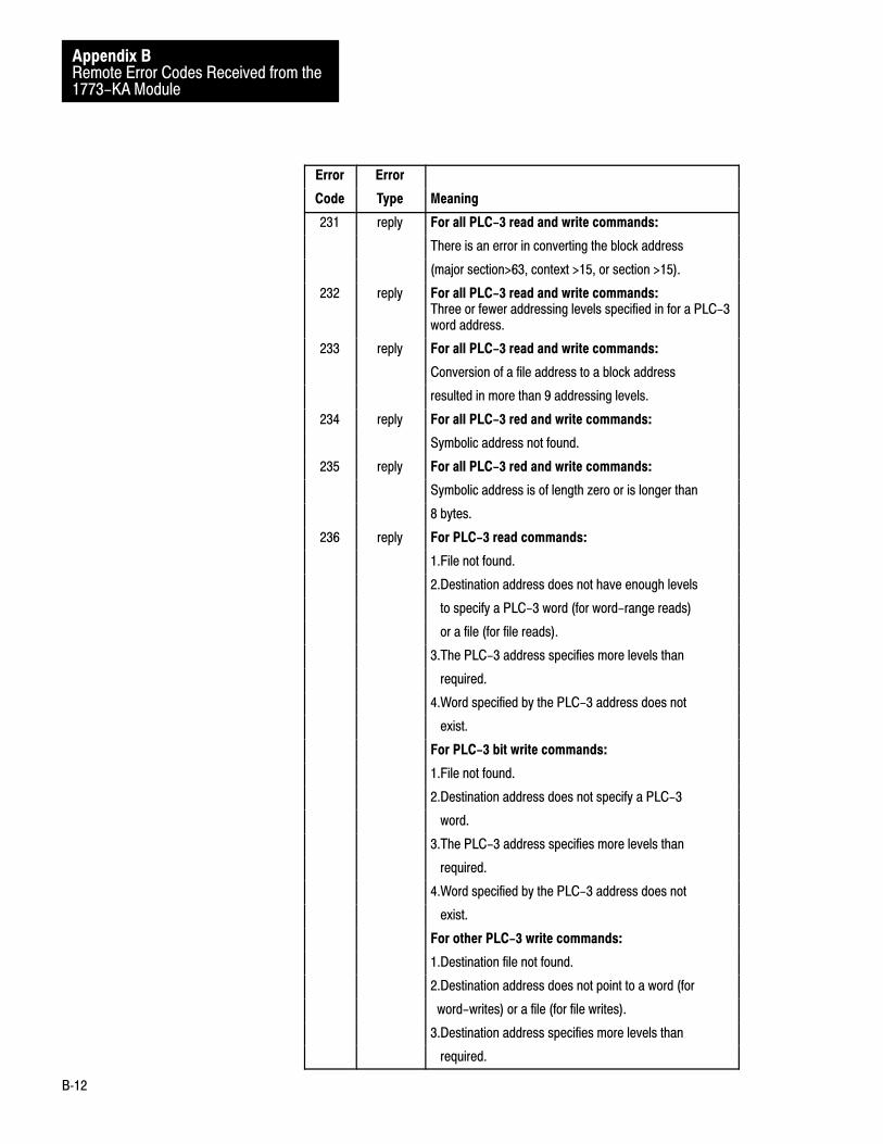
Remote Error Codes Received from the1773-KA Module
Appendix B
B�12
Error Error
Code Type Meaning
231 reply For all PLC-3 read and write commands:
There is an error in converting the block address
(major section>63, context >15, or section >15).
232 reply For all PLC-3 read and write commands:Three or fewer addressing levels specified in for a PLC-3word address.
233 reply For all PLC-3 read and write commands:
Conversion of a file address to a block address
resulted in more than 9 addressing levels.
234 reply For all PLC-3 red and write commands:
Symbolic address not found.
235 reply For all PLC-3 red and write commands:
Symbolic address is of length zero or is longer than
8 bytes.
236 reply For PLC-3 read commands:
1.File not found.
2.Destination address does not have enough levels
to specify a PLC-3 word (for word-range reads)
or a file (for file reads).
3.The PLC-3 address specifies more levels than
required.
4.Word specified by the PLC-3 address does not
exist.
For PLC-3 bit write commands:
1.File not found.
2.Destination address does not specify a PLC-3
word.
3.The PLC-3 address specifies more levels than
required.
4.Word specified by the PLC-3 address does not
exist.
For other PLC-3 write commands:
1.Destination file not found.
2.Destination address does not point to a word (for
word-writes) or a file (for file writes).
3.Destination address specifies more levels than
required.
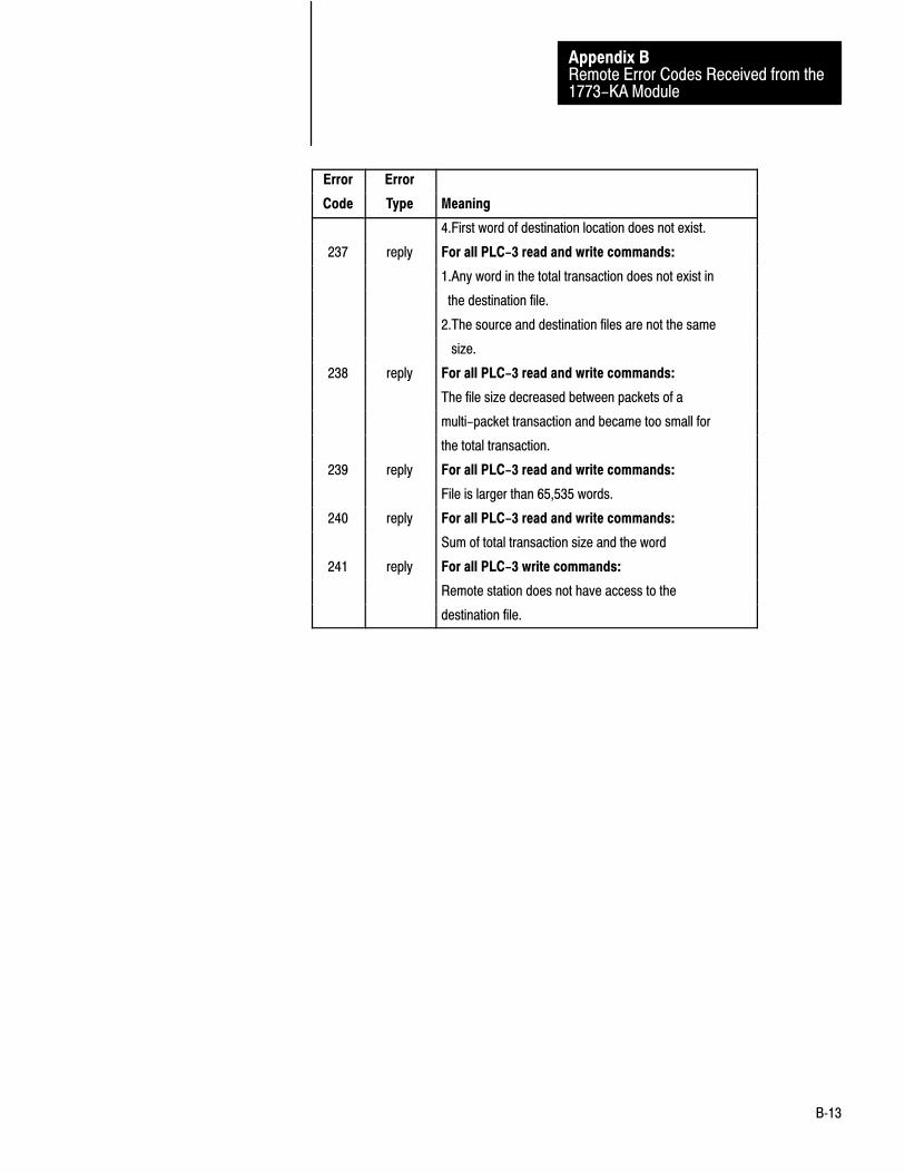
Remote Error Codes Received from the1773-KA Module
Appendix B
B�13
Error Error
Code Type Meaning
4.First word of destination location does not exist.
237 reply For all PLC-3 read and write commands:
1.Any word in the total transaction does not exist in
the destination file.
2.The source and destination files are not the same
size.
238 reply For all PLC-3 read and write commands:
The file size decreased between packets of a
multi-packet transaction and became too small for
the total transaction.
239 reply For all PLC-3 read and write commands:
File is larger than 65,535 words.
240 reply For all PLC-3 read and write commands:
Sum of total transaction size and the word
241 reply For all PLC-3 write commands:
Remote station does not have access to the
destination file.

Remote Error Codes Received from the1773-KA Module
Appendix B
B�14
If the remote station has a 1771–KG, 1771–KA, or 1774–KA module, theremote error codes will have the meanings listed in the table below:
Error
Code Meaning
81 This error is sent from the remote station if the command
message was incorrect. This includes the command code,
subcommand code, and size of the command or the requested
reply size. This error results in the setting of the remote error bit
for the associated rung.
83 Some condition exists at the remote PC that requires manual
intervention:
The cable between the module and the PC is unplugged.
The PC is faulted.
Either results in setting the remote error bit for the associates
rung.
84 Execution of a message at the remote station was aborted
because of a hard communication error on the cable or on
backplane access between the module and the PC. This error
results in the setting of the remote error bit for the associates
rung.
85 An attempt to access an illegal address in the remote PC has
aborted message execution. Illegal accesses may result from:
Access outside the data table as defined at the remote station.
Access outside a memory access window (protected commands
only).
Either results in setting the remote error bit for the associated
rung.
86 Execution of a command is disabled at the remote station by a
DIP switch option. This error results in setting the remote error
bit for the associates rung.
87 The remote PC is in PROGRAM or REMOTE PROGRAM
mode, or the remote KA is in download mode. This error results
in setting the remote error bit for the associated rung.
88 Execution of protected commands at the remote station is
inhibited because its PROG light is on. This error results in
setting the remote error bit for the associated rung.
89 The remote station has no memory to store messages. This error
will only be signalled after 5 re-tries at half second intervals.
Remote Error codes receivedfrom the 1771-KE/KF, 1771-KG,1771-KA, and 1774-KA Modules
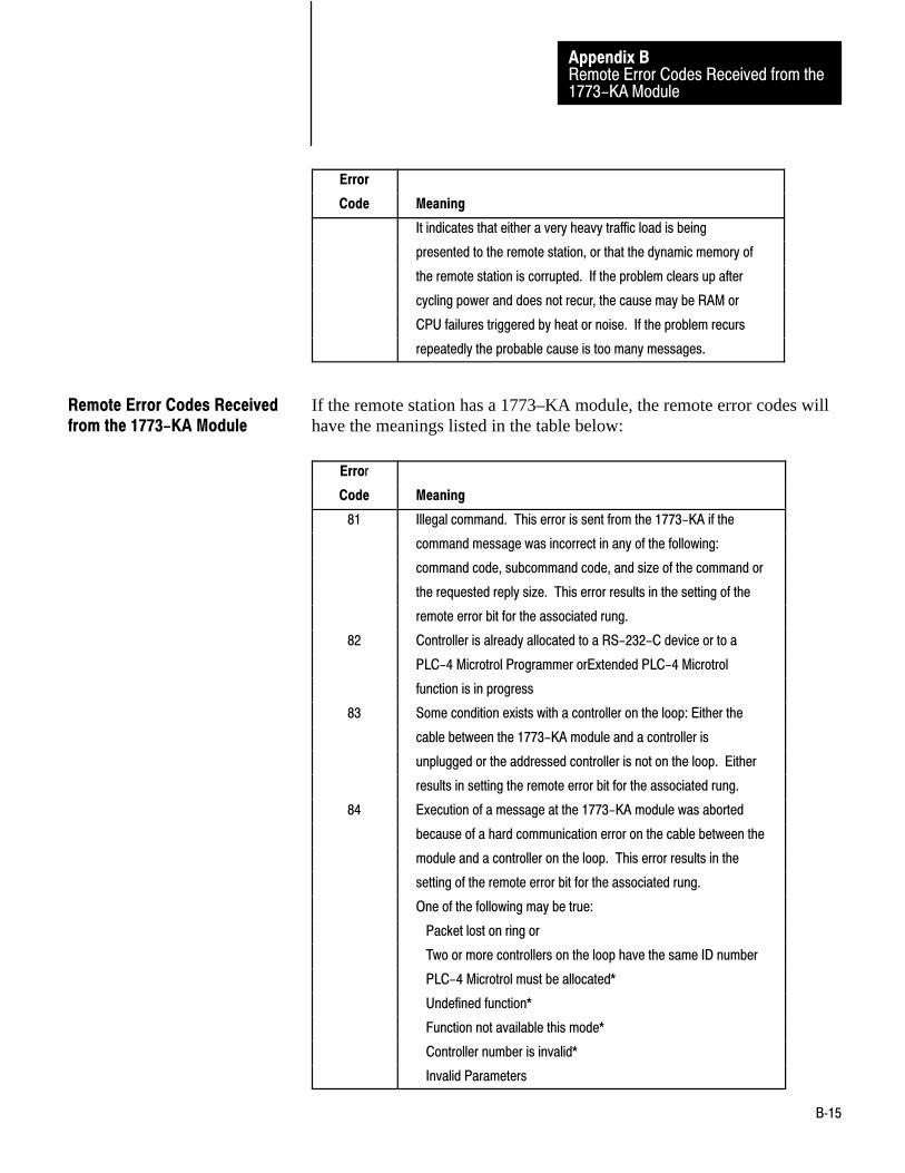
Remote Error Codes Received from the1773-KA Module
Appendix B
B�15
Error
Code Meaning
It indicates that either a very heavy traffic load is being
presented to the remote station, or that the dynamic memory of
the remote station is corrupted. If the problem clears up after
cycling power and does not recur, the cause may be RAM or
CPU failures triggered by heat or noise. If the problem recurs
repeatedly the probable cause is too many messages.
If the remote station has a 1773–KA module, the remote error codes willhave the meanings listed in the table below:
Error
Code Meaning
81 Illegal command. This error is sent from the 1773-KA if the
command message was incorrect in any of the following:
command code, subcommand code, and size of the command or
the requested reply size. This error results in the setting of the
remote error bit for the associated rung.
82 Controller is already allocated to a RS-232-C device or to a
PLC-4 Microtrol Programmer orExtended PLC-4 Microtrol
function is in progress
83 Some condition exists with a controller on the loop: Either the
cable between the 1773-KA module and a controller is
unplugged or the addressed controller is not on the loop. Either
results in setting the remote error bit for the associated rung.
84 Execution of a message at the 1773-KA module was aborted
because of a hard communication error on the cable between the
module and a controller on the loop. This error results in the
setting of the remote error bit for the associated rung.
One of the following may be true:
Packet lost on ring or
Two or more controllers on the loop have the same ID number
PLC-4 Microtrol must be allocated*
Undefined function*
Function not available this mode*
Controller number is invalid*
Invalid Parameters
Remote Error Codes Receivedfrom the 1773-KA Module

Remote Error Codes Received from the1773-KA Module
Appendix B
B�16
Error
Code Meaning
Improper command may return this error code*
EEPROM bad*
No reply queued
Device resource unavailable
*if these error codes occur, they will most likely occur during
start- up.
85 This error occurs if you attempt to access an illegal address in a
controller. The 1773-KA module then aborts the message.
Illegal accesses may result because:
Invalid Read/Write length or
All Bit writes not to the same PLC-4 or
Invalid address or
Memory Protection Violation
86 The command cannot be executed because of the switch
settings on the 1773-KA module.
87 The controller you have addressed is in Program mode. This
error results in setting the remote error bit for the associated
rung.
88 Reserved
89 1773-KA unable to buffer message in memory. This error will
only be signalled after 5 re-tries at half second intervals. It
indicates that either a very heavy traffic load is being presented
to the remote station, or that the dynamic memory of the remote
station is corrupted. If the problem clears up after cycling
power and does not recur the cause may be RAM or CPU
failures triggered by heat or noise. If the problem recurs
repeatedly the probable cause is too many messages.
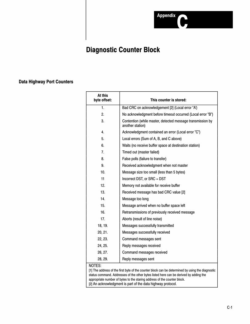
Appendix
C
C�1
Diagnostic Counter Block
At thisbyte offset: This counter is stored:
1. Bad CRC on acknowledgement [2] (Local error �A')
2. No acknowledgment before timeout occurred (Local error �B")
3. Contention (while master, detected message transmission byanother station)
4. Acknowledgment contained an error (Local error "C")
5. Local errors (Sum of A, B, and C above)
6. Waits (no receive buffer space at destination station)
7. Timed out (master failed)
8. False polls (failure to transfer)
9. Received acknowledgment when not master
10. Message size too small (less than 5 bytes)
11 Incorrect DST, or SRC = DST
12. Memory not available for receive buffer
13. Received message has bad CRC value [2]
14. Message too long
15. Message arrived when no buffer space left
16. Retransmissions of previously received message
17. Aborts (result of line noise)
18, 19. Messages successfully transmitted
20, 21. Messages successfully received
22, 23. Command messages sent
24, 25. Reply messages received
26, 27. Command messages received
28, 29. Reply messages sent
NOTES:[1] The address of the first byte of the counter block can be determined by using the diagnostic
status command. Addresses of the other bytes listed here can be derived by adding the
appropriate number of bytes to the staring address of the counter block.
[2] An acknowledgment is part of the data highway protocol.
Data Highway Port Counters

Diagnostic Port CountersAppendix C
C�2
At this
byte offset: This counter is stored:
1,2. Command messages sent
3,4. Reply messages received
5,6. Command messages received
7,8. Reply messages sent
9,10. ACKs received
11,12. ACKs sent
13,14. NAKs received
15,16. NAKs sent
17. Undeliverable reply messages
18,19. Computer link timeout (preset to 500 msec)
20. Maximum number of NAKs accepted per message (preset
to 10)
21. Maximum number of ENQs sent per messge (preset to 10)
22. Current NAK count
23. Current ENQ count
Modem Port Counters

Appendix
D
D�1
Detailed Flowcharts
The flowcharts in chapter 10 and 11 give a simplified view of an exampleof software logic for implementing full–duplex protocol. In thisappendix, we present flowcharts which give a detailed view of an exampleof software logic for implementing full–duplex protocol.
We have not shown any error checking or recovery relating to interactionwith the modem handshake driver, a third process. To do this wouldoverly complicate the flow charts, and in many cases, such error checkingand recovery are not needed.
Figure D.1Data Flow Program for Full-Duplex Protocol
Data Link Layer
Physical Link Layer
SENDCTLSENDDATASENDETX
XMIT
NetworkLayer
GETCODE RCVE
EmptyBuffers
ReceivedMessages
Messagesto be sent
MessagesWhichHave Been Sent(Or Have Failed)Row Output
Bytes Messages
DLEENQ
Separa-tor
Row Input Bytes Messages
DLEENQ
DLE ACK DLE ACK
DLE NAK
10071–I
Multiplexer
Overview

Detailed Flowcharts
Appendix D
D�2
Figure D.2Transmitter Routine for Full=-Duplex Protocol
XMIT
GETMSG
Get Messagefrom Network Layer
Reset NAKand Timeout Counters
SENDM
Send Message
WTAK
Wait for ACK,NAK or Timeout
SENDCTL
SendDLEENQ
ReceivedDLE NAK ?
ReceivedDLE ACK ?
3* NAKsReceived for this Message ?
3* Timeouts for this Message ?
SIGFAIL SIGOK SIGFAIL
Tell Net-work Layer of Failure
Tell NetworkLayer Mesage Was Sent
Tell Net-work Layer of Failure
10072–I
Yes
No
No
Yes
No
Yes
Yes
No
Internal Storage:• NAK Counter• Timeout Counter
Legend:• Default value used by the mod-ule

Detailed Flowcharts
Appendix D
D�3
Figure D.3Receiver Routine for Full-Duplex Protocol
RCVE
GET BUFFER
Get a Buffer
LAST = NAK
Reset Receiver Error Flag
GET CODE
Get Next Input
DLE STX ?
XMSG
Transfer Message to Network Layer
IgnoreFlag (0) ?
Save Response (ACK or NACK) in LAST
SEND CTL
Transmit LAST
No
Yes
No
Yes
No
Yes
Yes
No
NOTE: XMSG Returns ACK,NACK, or 0 (for Ignored Message)
Variables:
• LAST: Value of Last Response
• HEADER: DST, SRC, CMD, STS and TNS from last message
• BUFFER: Whether an Empty Buffer is Read
• Receiver error flag
10073–I
Reset Buffer Flag; SetHeader to Illegal Value
ControlCode
?
DLE ENQ?
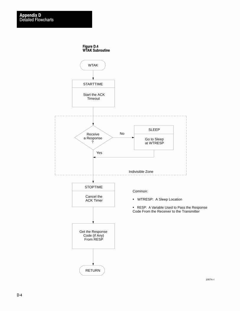
Detailed Flowcharts
Appendix D
D�4
Figure D.4WTAK Subroutine
RETURN
Get the Response Code (if Any) From RESP
STOPTIME
Cancel theACK Timer
Common:
• WTRESP: A Sleep Location
• RESP: A Variable Used to Pass the ResponseCode From the Receiver to the Transmitter
WTAK
STARTTIME
Start the ACK Timeout
Receivea Response ?
SLEEP
Go to Sleepat WTRESP
No
Yes
Indivisible Zone
10074–I

Detailed Flowcharts
Appendix D
D�5
Figure D.5SENDM Subroutine
RETURN
BCC
IncludeETX in BCC
Link Data Done ?
BCC
IncludeByte in BCC
SENDDATA
Send LinkData Byte
Yes
No
SENDM
Reset BCCAccumula-tor
SENDCTL
Send DLE STX
SENDETX
SendDLE ETX BCC
10075–I

Detailed Flowcharts
Appendix D
D�6
Figure D.6STARTTIME Subroutine
10076–I
STARTTIME
RETURN
An Implementation DependantRoutine that Schedules TIMEOUT
to Be Executed at the Expiration of an Internal of Time (Typically 12
Character Times)
Figure D.7STOPTIME Subroutine
10077–I
STOPTIME
RETURN
An Implementation DependantRoutine to Cancel TIMEOUT

Detailed Flowcharts
Appendix D
D�7
Figure D.8TIMEOUT Subroutine
10078–I
TIMEOUT
RETURN
Scheduled By:
•
Aborted By:
•
WAKEUP
Wake Up the ProcessSleeping at WTRESP
(If Any)
STARTTIME
STOPTIME

Detailed Flowcharts
Appendix D
D�8
Figure D.9GETMSG Subroutine
GETMSG
RETURN
UNLINK
Remove aMessage From
Queue
Boxed area above must be executedindivisibly, i.e., with the scheduler or interrupts disabled, depending onimplementation.
Common:
•
•
Output:: •
No
SLEEP
Go to SleepAt WTMSG
10079–I
ISQueueEmpty
?
Yes
WTMSG
Output Queue
A Message

Detailed Flowcharts
Appendix D
D�9
Figure D.10SIGOK/SIGFAIL Subroutine
SIGOK
Place SuccessCode in Message Control Block
LINK
Place Message on RETURN Queue
WAKEUP–NET
Implementation–Dependent Procedure to Tell Network Layer that RETURNQueue Entry Has Been Made
RETURN
SIGFAIL
Place FailedCode in Message Control Block
10080–I

Detailed Flowcharts
Appendix D
D�10
Figure D.11 shows the transmitter (XMIT) and receiver (RCVE) routinessharing the transmit side of the UART. XMIT transmits messages andinquiries. RCVE transmits responses. Therefore, each must wait until theother is thru before it can transmit thru the UART. The TXALLOC andTXFREE subroutines work together to ensure that XMIT and RVCE donot try to use the UART at the same time. TXALLOC and TXFREE arecalled in the SENDCTRL, SENDETX, and SENDDATA subroutines(Figure D.12, Figure D.13, and Figure D.14).
Figure D.11Sharing the Transmit Side of the UART
TXALLOC
UART Usage
TXFREE
XMIT RCVE
XMIT RCVE
Not–In–UseSignal
10081–I
UART Sharing
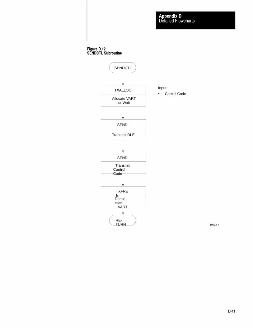
Detailed Flowcharts
Appendix D
D�11
Figure D.12SENDCTL Subroutine
SENDCTL
TXALLOC
Allocate VART or Wait
SEND
Transmit DLE
SEND
TransmitControlCode
TXFREE
Deallo-cate VART
RE-TURN
Input:
• Control Code
10082–I

Detailed Flowcharts
Appendix D
D�12
Figure D.13SENDTX Subroutine
SENDTX
TXALLOC
Allocate UART or Wait
SEND
Transmit DLE
SEND
Transmit ETX
Zero Out AnyPrevious Response Code at RESP
SEND
Transmit BCC
TXFREE
Deallocate UART
RETURN
Input:
• BCC
Common:
• RESP: The Response Code Variable
10083–I

Detailed Flowcharts
Appendix D
D�13
Figure D.14SEND Subroutine
SEND
Disable Processor Interrupts
Enable UARTTransmit Interrupt
UARTTransmitter Empty ?
Yes
Disable UARTTransmit Interrupt
NoSLEEP
Suspend at TXWAIT
Output Byte to UART
Enable Processor Interrupts
Return
Indivisible Zone
NOTE: This figure assumes the use ofa Z80 SIO
Input:
• Link Data Byte
Common:
• TXWAIT: A Sleep Variable
10084–I

Detailed Flowcharts
Appendix D
D�14
Figure D.15SENDDATA Subroutine
SENDDATA
TXALLOC
Allocate UART or Wait
SEND
Transmit Link Data Byte
Is DataByte DLE ?
SEND
Transmit aSecond DLE
TXFREE
De–allocate UART
RETURN
Yes
No
Input:
• Link Data Byte
10085–I

Detailed Flowcharts
Appendix D
D�15
Figure D.16TXALLOC Subroutine
10086-I
TXAL-LOC
UARTIn Use ?
Set IN–USE Flag
RETURN
SLEEP
Wait at TXALWTUntil UART is Free
Indivisible Zone
Common:• IN–USE Flag
• TXALWT: A Sleep Variable
No
Yes
11667
Figure D.17TXFREE Subroutine
10087-I
TXFREE
Reset IN–USE Flag
WAKEUP
ContinueAny Process at TXALWT
RETURN
Common:
• IN–USE Flag
• TXALWT: A Sleep Variable

Detailed Flowcharts
Appendix D
D�16
Figure D.18TRANSMIT INTERRUPT Subroutine
10088-I
WAKEUP
TRANSMITINTERRUPT
INTERRUPTRETURN
Resume ProcessSleeping AtTXWAIT
NOTE: a Z80 S10.This figure assumes the use of
NOTE: UART transmit interrupt mustbe enabled and disabled withoutaffecting the current state of the receive flags.
and status interrupt enable
Figure D.19SLEEP and WAKEUP Subroutines
10089-I
RETURNRETURN
An Implementation DependentRoutine to Suspend Own
Process at a Sleep VariableUntil Another Process Wakes
This One UP
An Implementation DependentRoutine to Wake Up the
Process at a Sleep Variableif Any is Sleeping There
Input:
The Address of a Sleep Variable.
Sleep Variables:
Typically an address of a stack ora process or context save area.
A Process can suspend itself and place its address in a sleepvariable.
Subsequently another process canwake up the sleeping process byreferring to sleep variable. Whenno process is sleeping at a sleepvariable, a WAKEUP has no effect.
Input:
The Address of a Sleep Variable.
SLEEP WAKEUP
•
•
•
•
•
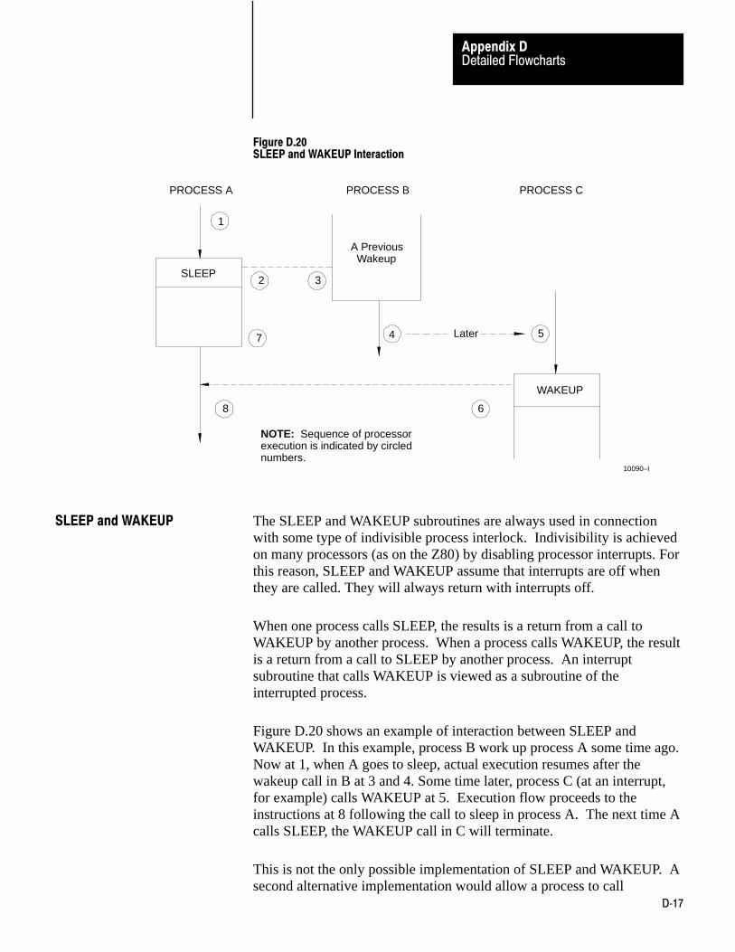
Detailed Flowcharts
Appendix D
D�17
Figure D.20SLEEP and WAKEUP Interaction
PROCESS A PROCESS B PROCESS C
SLEEP
A Previous Wakeup
Later
WAKEUP
2
1
7
8
3
4
6
5
NOTE: Sequence of processorexecution is indicated by circlednumbers.
10090–I
The SLEEP and WAKEUP subroutines are always used in connectionwith some type of indivisible process interlock. Indivisibility is achievedon many processors (as on the Z80) by disabling processor interrupts. Forthis reason, SLEEP and WAKEUP assume that interrupts are off whenthey are called. They will always return with interrupts off.
When one process calls SLEEP, the results is a return from a call toWAKEUP by another process. When a process calls WAKEUP, the resultis a return from a call to SLEEP by another process. An interruptsubroutine that calls WAKEUP is viewed as a subroutine of theinterrupted process.
Figure D.20 shows an example of interaction between SLEEP andWAKEUP. In this example, process B work up process A some time ago.Now at 1, when A goes to sleep, actual execution resumes after thewakeup call in B at 3 and 4. Some time later, process C (at an interrupt,for example) calls WAKEUP at 5. Execution flow proceeds to theinstructions at 8 following the call to sleep in process A. The next time Acalls SLEEP, the WAKEUP call in C will terminate.
This is not the only possible implementation of SLEEP and WAKEUP. Asecond alternative implementation would allow a process to call
SLEEP and WAKEUP

Detailed Flowcharts
Appendix D
D�18
WAKEUP without losing immediate control of the processor. If B wakesup A, context switching would be deferred until B itself has executed aSLEEP.
A third alternative would cause a context switch if a process performed aWAKEUP on a higher priority process. If a WAKEUP had beenperformed on a lower priority process, the context switch would bedeferred until the first process has gone to sleep.
The first alternative is the result of implementing the driver totally at theinterrupt level where scheduling is dictated by the interrupt daisy chainhardware.
The third alternative would be used if the driver were implemented astasks under a multitasking operating system. Such an implementationmight be easier, but would probably be limited to lower communicationrates.
At powerup, the Z80 processor starts executing code at location 0. ThePOWERUP subroutine starts at XMIT and RCVE processes by executinga SPAWN. A SPAWN is very similar to a WAKEUP except that thecorresponding SLEEP is imaginary and is located prior to the firstinstruction of the spawned process.
Figure D.21POWERUP Routine
POWERUP
SPAWNRCVE
SPAWNXMIT
ContinueInitialization
10091–I
POWERUP

Detailed Flowcharts
Appendix D
D�19
Figure D.22Message Queue
FIRST
LAST
NEXTMESSAGE
SIZESTATUS
Network Data Block
NEXTMESSAGE
SIZESTATUS
Network Data Block
0MESSAGE
SIZESTATUS
Network Data Block
ROOT MESSAGECONTROL BLOCKS MESSAGES
The Address of aQueue is theAddress of its Root.
NOTE: Messages are added to theend of the queue and removed fromthe head.
10092–I
Figure D.23UNLINK Subroutine
RETURN
An Implementation
Input:
UNLINK
Address of Queue
Output:
Message Control Block
Dependent Routinethat Removes a
Message from a Queue
•
•
10093–I

Detailed Flowcharts
Appendix D
D�20
Figure D.24LINK Subroutine
RETURN
An Implementation
Input:LINK
10094–I
Address of Queue Message Block
Dependent Routinethat Places a
Message onto a Queue
•
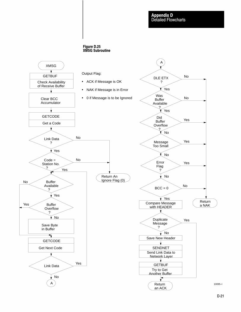
Detailed Flowcharts
Appendix D
D�21
Figure D.25XMSG Subroutine
XMSG
GETBUF
Check Availabilityof Receive Buffer
Clear BCCAccumulator
GETCODE
Get a Code
Link Data ?
Code =Station No. ?
BufferAvailable ?
BufferOverflow ?
Save Bytein Buffer
GETCODE
Get Next Code
Return AnIgnore Flag (0)
Link Data
A
No
Yes
No
Yes
Yes
Yes
No
No
No
Yes
Output Flag:
• ACK if Message is OK
• NAK if Message is in Error
• 0 if Message is to be Ignored
Returnan ACK
GETBUF Try to GetAnother Buffer
SENDNETSend Link Data to Network Layer
Save New Header
DuplicateMessage ?
Compare Message with HEADER
A
DLE ETX ?
Was BufferAvailable ?
Did BufferOverflow ?
MessageToo Small
ErrorFlag ?
No
Yes
BCC = 0
Returna NAK
10095–I
No
Yes
Yes
Yes
Yes
No
No
No
No
Yes
Yes
No

Detailed Flowcharts
Appendix D
D�22
Figure D.26GETCODE Subroutine
GETCODE
GETRAW
Get Byte From UART
DLE ?
GETRAW
Get Byte From UART
DLE ?
No
Yes
BCC
Add Data Byte to BCC
Return Byteand Data Flag
Save ACK orNAK in RESP
WAKEUP
Resume XMIT if Sleeping at WTRESP ACK or NAK
?
Yes
No
No
Yes
No
Yes
ETX ?
Return Byteand Control FlagBCC
Include ETX
GETRAW
Get Low Byte of BCC
BCC
Include in Check
GETRAW
Get High Byte of CRC
BCC
Include in Check
Return EXTand Control Flag
10096–I
Output:
• BYTE –– What Was Received
• Control/Data Flag –– Set if BYTE is a control character which was preceded by a DLE
NOTE: CRC Should Now Equal Zero

Detailed Flowcharts
Appendix D
D�23
Figure D.27GETRAW Subroutine
GETRAW
Disable Processor Interrupts
Enable UARTReceive Interrupt
Byte inUART ?
Disable UARTReceived Interrupt
Check Parity,Framing, and ???
SLEEP
Wait For RXD Interrupt at RXDWAIT
Error ?
Get ByteFrom UART
Enable Processor Interrupts
RETURN
Set Receiver Error Flag
DiscardBad Data
Reset UART Error Flag
10097–I
NOTE: This figure assumes the use ofa Z80 S10.
No
Yes
Yes
No

Detailed Flowcharts
Appendix D
D�24
Figure D.28Receive Interrupt Subroutine
10098-I
WAKEUP
RECEIVEINTERRUPT
INTERRUPTRETURN
NOTE: of a Z80 S10This figure assumes the use
AT RXDWAIT
Figure D.29SENDNET Subroutine
10099–I
SENDNET
Reset theBUFFER Flag
RETURN
An ImplementationDependent Routine
to Put a Messageon the INPUT Queue
Input:
• Message Buffer
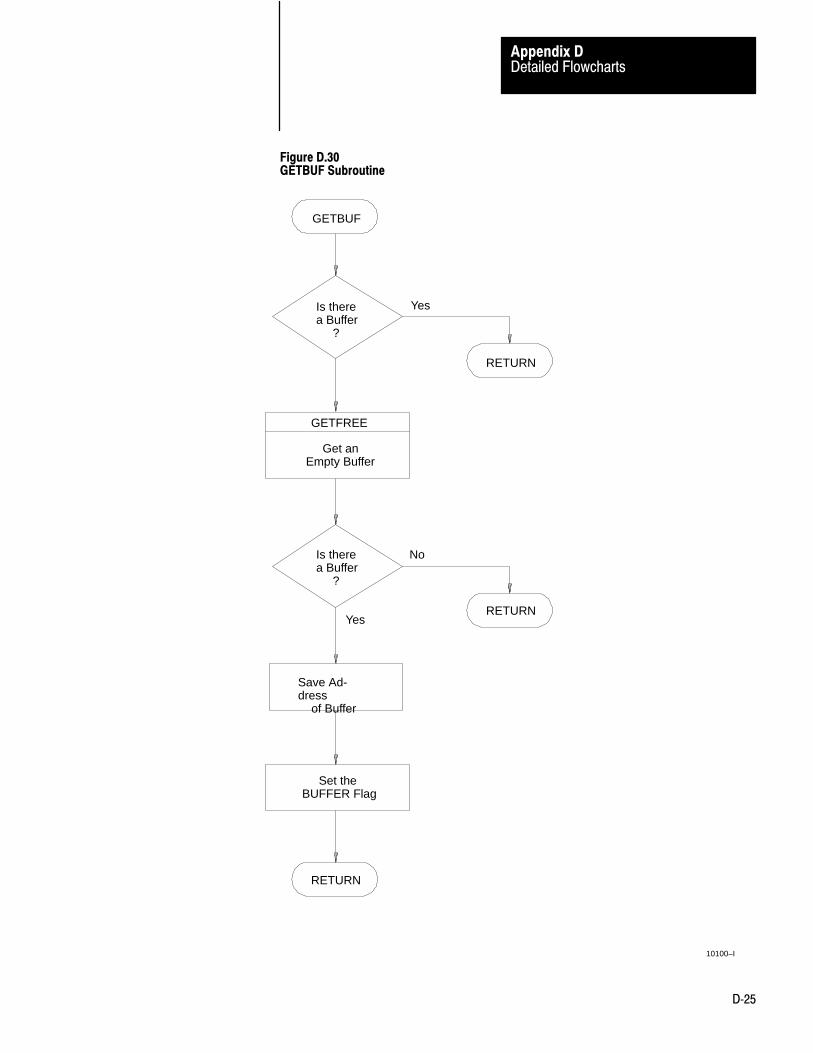
Detailed Flowcharts
Appendix D
D�25
Figure D.30GETBUF Subroutine
GETBUF
Is therea Buffer ?
GETFREE
Get anEmpty Buffer
RETURN
Yes
NoIs therea Buffer ?
RETURNYes
Save Ad-dress of Buffer
Set theBUFFER Flag
RETURN
10100–I
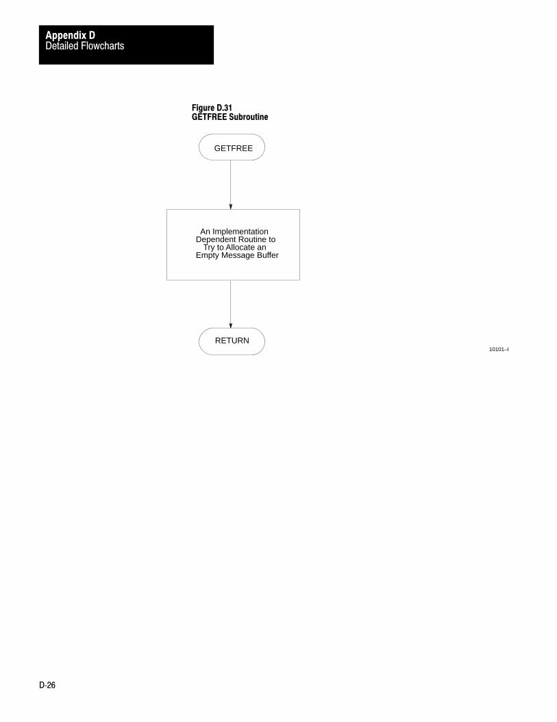
Detailed Flowcharts
Appendix D
D�26
Figure D.31GETFREE Subroutine
10101–I
GETFREE
RETURN
An Implementation Dependent Routine to
Try to Allocate anEmpty Message Buffer

Symbols
**Empty**, 2�24
A
Addresses, 4�3, 4�5
Addressing rules, 4�1addressing a file, 4�7addressing a word, 4�8, 4�11addressing a word range, 4�8, 4�10expressions, 4�13, 4�14number systems, 4�2PLC-3 address specifications, 4�7PLC/PLC-2 address specifications,
4�10remote station address specifications,
4�12symbols, 4�4, 4�5, 4�6
Application layer protocol, 12�6ADDR (address), 12�10application message fields, 12�6CMD and FNC (command and function),
12�7ETX STS (extended status), 12�9STS (status), 12�8
Applications of 1775-KA modules, 1�8
Assignment command, 6�2, 6�3, 6�4
B
Backup, 2�24, 2�27, 2�28, 2�29
Basic command set, A�8
C
Comments, 6�11
Computer to PC communication, 9�1
Control file word, 3�4
CountersData Highway port counters, C�1modem port counters, C�2
CREATE Command, 6�5
D
Data transfers, 3�6
DELETE Command, 6�5
E
Editing, 5�1editing message procedures, 5�2, 5�3editing the message instruction, 5�1,
5�2
Error codes, B�1local error codes, B�1, B�4remote error codes, B�3reply error codes, B�4
Error Reporting, 7�1access to error block, 7�5error block operation, 7�2error monitoring, 7�2recovery from errors, 7�1reporting error codes, 7�1
Execute Command, 6�6
EXIT command, 6�6
Expressions, 4�13, 4�14
F
Flowchart, D�1
Full-Duplex protocol, 10�1block check, 10�5definition of link and protocol, 10�1full-duplex protocol diagrams, 10�17functions, 6�9message characteristics, 10�8receiver actions, 10�13transmission codes, 10�2transmitter actions, 10�9two-way simultaneous operation, 10�6
Full-duplex protocol, link-layer messagepackets, 10�4
G
GOTO Command, 6�7
H
Half-Duplex Protocol, 11�1
Half-Duplex protocolhalf-duplex protocol diagrams, 11�13line monitoring, 11�20protocol environment definition, 11�7
Index

IndexI–2
Half-duplex protocolblock check, 11�6link-layer packets, 11�4multidrop link, 11�1transmission codes, 11�2
Hardware Installation, 2�1
I
IF Command, 6�7
Indicators, 2�5
Installation, 2�1RS-232-C cable, 2�6
L
Line monitor, building one, A�2
LIST, 2�19, 2�20, 2�21, 2�22, 2�24, 2�25, 2�26, 2�28, 2�29
Local error codes, B�1
Local error codes, B�4
M
Message Formats, A�1
Message formatsbasic command set, A�1PLC-3 commands, A�1Privileged commands, A�1
Message procedure commands, 6�1assignment command, 6�2CREATE command, 6�5DELETE command, 6�5execute command, 6�6EXIT command, 6�6GOTO command, 6�7IF command, 6�7ON_ERROR command, 6�9STOP Command, 6�9
Messge procedure commands,ON_ERROR command, 6�8
N
Network layer protocol, 12�1CMD (High Nibble), 12�4
DST and STC, 12�4network model, 12�2network packet fields, 12�3program and message types, 12�1STS (Low Nibble), 12�4TNS, 12�5
Number system, 4�2
O
ON_ERROR Command, 6�8, 6�9
P
PLC-3 Address Specifications, 4�7
PLC-3 commands, A�13
PLC/PLC-2 address specifications, 4�10
Privileged commands, A�20
Programming examples, 8�1
R
Remote error codes, B�3
Remote station address specifications, 4�12
Reply error codes, B�1, B�4
reply error codes, B�1
S
Software features, 1�5
Specifications, 1�6
STOP Command, 6�9
Switches, 2�1
T
Terminology, 1�3, 3�1

Publication 1775�6.5.1 - October, 1992Supersedes 1775-6.5.1 January 1985
Allen�Bradley, a Rockwell Automation Business, has been helping its customers improve pro�ductivity and quality for more than 90 years. We design, manufacture and support a broad rangeof automation products worldwide. They include logic processors, power and motion controldevices, operator interfaces, sensors and a variety of software. Rockwell is one of the worldsleading technology companies.
Worldwide representation.
Argentina • Australia • Austria • Bahrain • Belgium • Brazil • Bulgaria • Canada • Chile • China, PRC • Colombia • Costa Rica • Croatia • Cyprus • Czech Republic •Denmark • Ecuador • Egypt • El Salvador • Finland • France • Germany • Greece • Guatemala • Honduras • Hong Kong • Hungary • Iceland • India • Indonesia •
Ireland • Israel • Italy • Jamaica • Japan • Jordan • Korea • Kuwait • Lebanon • Malaysia • Mexico • Netherlands • New Zealand • Norway • Pakistan • Peru •Philippines • Poland • Portugal • Puerto Rico • Qatar • Romania • Russia�CIS • Saudi Arabia • Singapore • Slovakia • Slovenia • South Africa, Republic • Spain •Sweden • Switzerland • Taiwan • Thailand • Turkey • United Arab Emirates • United Kingdom • United States • Uruguay • Venezuela • Yugoslavia
Allen�Bradley Headquarters, 1201 South Second Street, Milwaukee, WI 53204 USA, Tel: (1) 414 382�2000 Fax: (1) 414 382�4444
Publication 1775�6.5.1 - October, 1992Supersedes 1775-6.5.1 January 1985
PN 404639601Copyright 1992 Allen�Bradley Company, Inc. Printed in USA
Recommended