142 General Catalogue 2011-2012 SOCOMEC
appl
i_08
0_a
FUSERBLOC Fuse combination switches
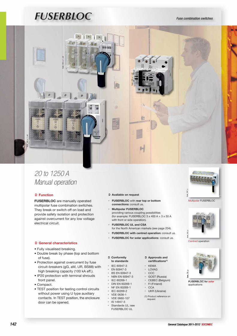
20 to 1250 AManual operation
fuse
r_53
9_a_
1_ca
t
fuse
r_53
2_a_
1_ca
t
fuse
r_54
8_a_
1_ca
t
Function‹
FUSERBLOC are manually operated multipolar fuse combination switches.They break or switch off on load and provide safety isolation and protection against overcurrent for any low voltage electrical circuit.
Conformity to standards
‹
IEC 60947-3EN 60947-3BS EN 60947-3NBN EN 60947-3IEC 60269-1DIN EN 60269-1NF EN 60269-1IEC 60269-2VDE 0636-1VDE 0660-107IS 14947-3Standards UL: see FUSERBLOC UL
••••••••••••
Approvals and certifications(1)
‹
KEMALOVAGCCCGOST (Russia)CEBEC (Belgium)FI (Finland)CCAUKR (Ukraine)
(1) Product reference on request.
••••••••
General characteristics‹
• Fully visualised breaking.• Double break by phase (top and bottom
of fuse).• Protection against overcurrent by fuse
circuit-breakers (gG, aM, UR, BS88) with high breaking capacity (100 kA eff.).
• IP20 protection with terminal shrouds front panel.
• Compact.• TEST position for testing control circuits
without power using U type auxiliary contacts. In TEST position, the enclosure door can be opened.
Available on request‹
FUSERBLOC with rear top or bottom connections: consult us.
Multipolar FUSERBLOC providing various coupling possibilities (for example: FUSERBLOC 3 x 400 A + 3 x 50 A with front or side operation).
FUSERBLOC UL and CSA for the North American markets (see page 204).
FUSERBLOC with centred operation: consult us.
FUSERBLOC for solar applications: consult us.
•
•
•
•
• fuse
r_55
2_a
Centred operation
FUSERBLOC for solar applications
fuse
r_70
1_a
fuse
r_59
7_a
Multipolar FUSERBLOC
143General Catalogue 2011-2012SOCOMEC
Fuse combination switchesFUSERBLOC
What you need to know‹
• Along with the rating, FUSERBLOC is selected according to the fuse type and functional specifications. SOCOMEC FUSERBLOC can be equipped with NFC, DIN or BS88 fuses.
• The INSTALFUSE® v2 software carries out sizing calculations for low-voltage electrical installations and their fuse protection.
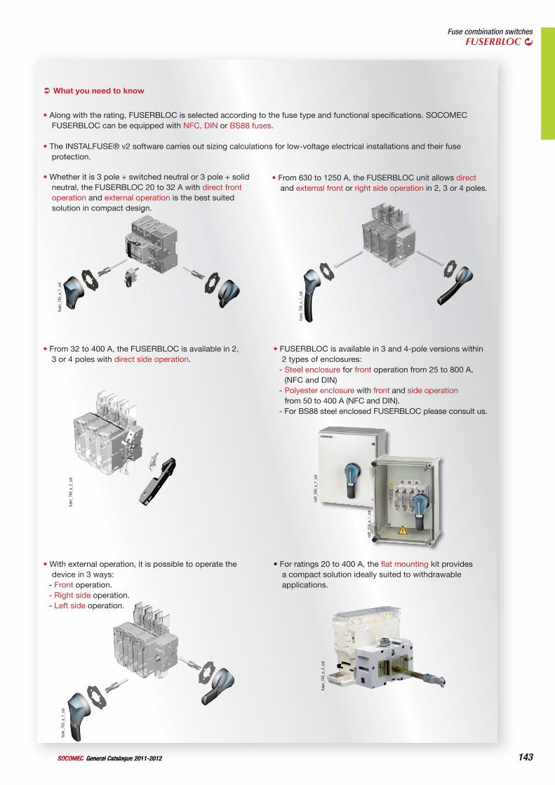
• Whether it is 3 pole + switched neutral or 3 pole + solid neutral, the FUSERBLOC 20 to 32 A with direct front operation and external operation is the best suited solution in compact design.
• From 630 to 1250 A, the FUSERBLOC unit allows direct and external front or right side operation in 2, 3 or 4 poles.
• From 32 to 400 A, the FUSERBLOC is available in 2, 3 or 4 poles with direct side operation.
• FUSERBLOC is available in 3 and 4-pole versions within 2 types of enclosures:
- Steel enclosure for front operation from 25 to 800 A, (NFC and DIN)
- Polyester enclosure with front and side operation from 50 to 400 A (NFC and DIN).
- For BS88 steel enclosed FUSERBLOC please consult us.
• With external operation, it is possible to operate the device in 3 ways:
- Front operation.- Right side operation.- Left side operation.
• For ratings 20 to 400 A, the flat mounting kit provides a compact solution ideally suited to withdrawable applications.
fuse
r_70
2_a_
2_ca
t
fuse
r_70
3_a_
1_ca
t
coff_
319_
a_1_
cat
coff_
295_
a_1_
cat
fuse
r_70
6_a_
2_ca
t
fuse
r_70
4_a_
1_ca
t
fuse
r_70
5_a_
1_ca
t
144 General Catalogue 2011-2012 SOCOMEC144
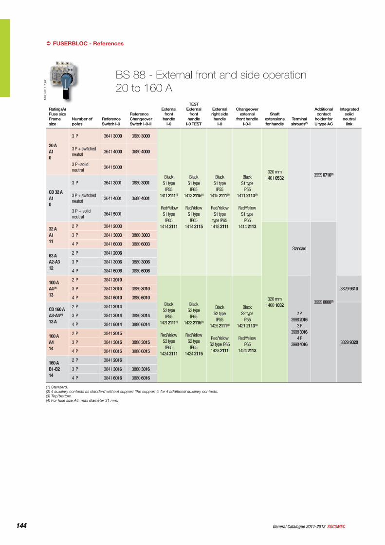
BS 88 - External front and side operation20 to 160 A
Rating (A)Fuse sizeFrame size
Number of poles
ReferenceSwitch I-0
ReferenceChangeoverSwitch I-0-II
External front
handle I-0
TEST External
front handle
I-0 TEST
External right side handle
I-0
Changeover external
front handleI-0-II
Shaft extensions for handle
Terminal shrouds(3)
Additional contact
holder for U type AC
Integrated solid
neutral link
20 AA10
3 P 3641 3000 3680 3000
Black S1 type
IP551411 2111(1)
Red/Yellow
S1 type IP65
1414 2111
Black S1 type
IP651413 2115(1)
Red/Yellow S1 type
IP651414 2115
Black S1 type
IP551415 2111(1)
Red/Yellow
S1 type type IP65
1418 2111
BlackS1 type
IP551411 2113(1)
Red/Yellow
S1 typeIP65
1414 2113
320 mm1401 0532
3999 0710(2)
3 P + switched neutral
3641 4000 3680 4000
3 P+solid neutral
3641 5000
CD 32 AA10
3 P 3641 3001 3680 3001
3 P + switched neutral
3641 4001 3680 4001
3 P + solid neutral
3641 5001
32 AA111
2 P 3841 2003
320 mm1400 1032
Standard
3999 0600(2)
3 P 3841 3003 3880 3003
4 P 3841 6003 3880 6003
63 AA2-A312
2 P 3841 2006
3 P 3841 3006 3880 3006
4 P 3841 6006 3880 6006
100 AA4 (4)
13
2 P 3841 2010
Black S2 type
IP551421 2111(1)
Red/Yellow S2 type
IP651424 2111
Black S2 type
IP651423 2115(1)
Red/Yellow S2 type
IP651424 2115
Black S2 type
IP551425 2111(1)
Red/Yellow
S2 type IP651428 2111
Black S2 type
IP551421 2113(1)
Red/Yellow
IP651424 2113
2 P3998 2016
3 P3998 3016
4 P3998 4016
3829 9310 3 P 3841 3010 3880 3010
4 P 3841 6010 3880 6010
CD 160 AA3-A4 (4)
13 A
2 P 3841 2014
3829 9320
3 P 3841 3014 3880 3014
4 P 3841 6014 3880 6014
160 AA414
2 P 3841 2015
3 P 3841 3015 3880 3015
4 P 3841 6015 3880 6015
160 AB1-B214
2 P 3841 2016
3 P 3841 3016 3880 3016
4 P 3841 6016 3880 6016
(1) Standard.(2) 4 auxiliary contacts as standard without support (the support is for 4 additional auxiliary contacts.(3) Top/bottom.(4) For fuse size A4: max diameter 31 mm.
FUSERBLOC - References‹fu
ser_
570_
a_2_
cat
145General Catalogue 2011-2012SOCOMEC 145
Fuse combination switchesFUSERBLOC
Rating (A)Fuse sizeFrame size
Number of poles
ReferenceSwitch I-0
ReferenceChangeoverSwitch I-0-II
External front
handle I-0
TEST External
front handle
I-0 TEST
External right side handle
I-0
Changeover external
front handleI-0-II
Shaft extensions for handle
Terminal shrouds(3)
Additional contact
holder for U type AC
Integrated solid
neutral link
CD 200 AA3-A4 (5)
13 A
2 P 3841 2019
Black S2 type
IP551421 2111(1)
Red/Yellow
S2 type IP65
1424 2111
Black S2 type
IP651423 2115(1)
Red/Yellow
S2 type IP65
1424 2115
Black S2 type
IP551425 2111(1)
Red/Yellow
S2 type IP65
1428 2111
Black S2 type
IP551421 2113(1)
Red/Yellow
S2 typeIP65
1424 2113
320 mm 1400 1032
2 P3998 2016
3 P3998 3016
4 P3998 4016
3999 0600(4)
3829 9320 3 P 3841 3019 3880 3019
4 P 3841 6019 3880 6019
200 AB1-B215
2 P 3841 2021
2 P3998 2025
3 P3998 3025
4 P3998 4025
3829 9325
3 P 3841 3021 3880 3021
4 P 3841 6021 3880 6021
250 AB1-B2-B315
2 P 3841 2024
3 P 3841 3024 3880 3024
4 P 3841 6024 3880 6024
315 AB1-B2-B316
2 P 3841 2032
3829 9339
3 P 3841 3032 3880 3032
4 P 3841 6032 3880 6032
400 AB1-B2-B3-B416
2 P 3841 2039
3 P 3841 3039 3880 3039
4 P 3841 6039 3880 6039
630 AC1-C217
2 P 3821 2063 Black S3 type
IP651433 3111(1)
Red/Yellow
S3 type IP65
1434 3111
Black S3 type
IP651437 3111(1)
Red/Yellow
S3 type IP65
1438 3111
320 mm 1400 1232
2 P3898 2080
3 P 3898 3080
4 P3898 4080
3829 9308
3 P 3821 3063
4 P 3821 6063
800 AC1-C2-C317
2 P 3821 2080
3 P 3821 3080
4 P 3821 6080
1250 AD118
2 P 3821 2120 Black S4 type
IP651443 3111(1)
3898 2120
3829 9312 3 P 3821 3120 3898 3120
4 P 3821 6120 3898 4120
(1) Standard.(2) 4 auxiliary contacts as standard without support (the support is for 4 additional auxiliary contacts.(3) Top/bottom.(4) 8 AC as standard without support (the support is for 8 additional auxiliary contacts.(5) For fuse size A4: max diameter 31mm
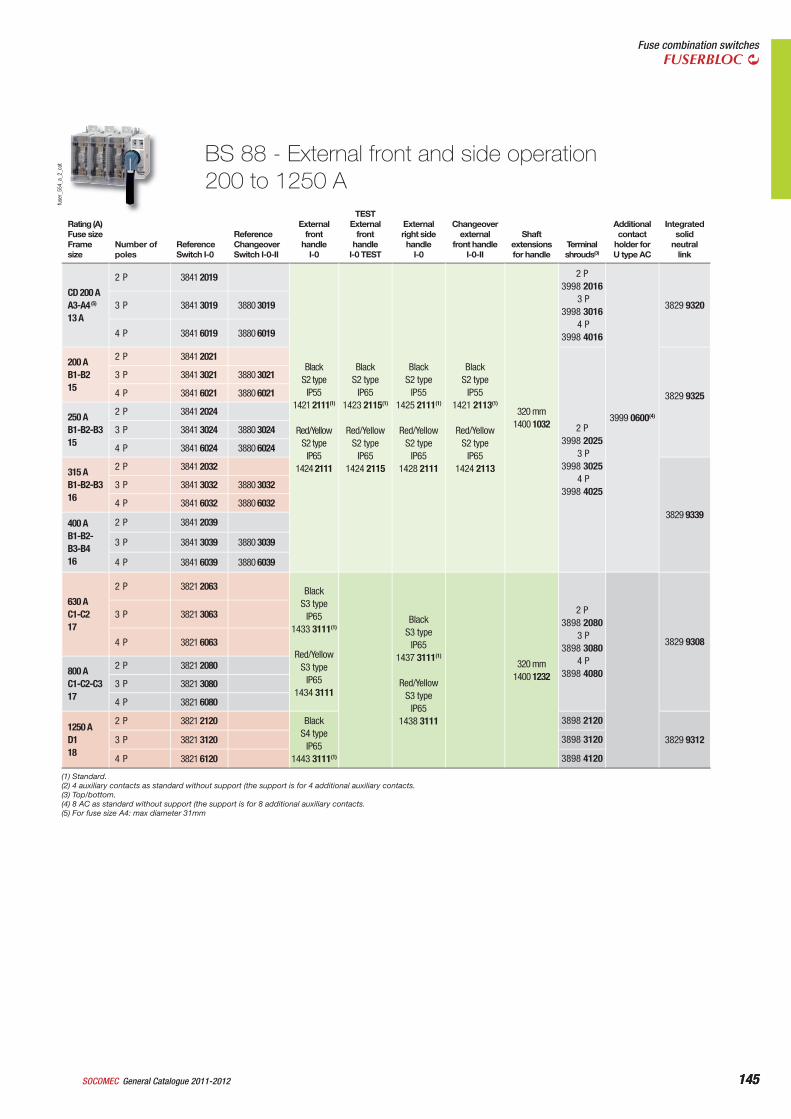
BS 88 - External front and side operation200 to 1250 A
fuse
r_55
4_a_
2_ca
t
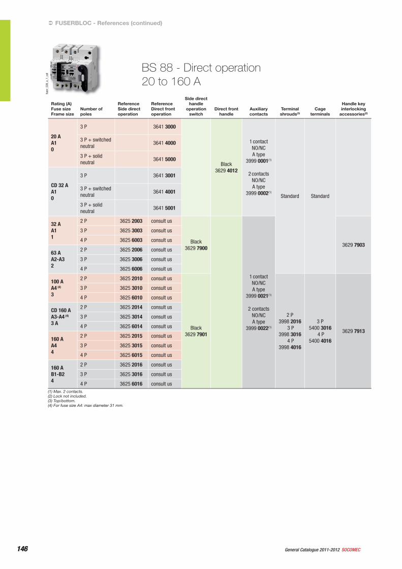
146 General Catalogue 2011-2012 SOCOMEC146
Rating (A)Fuse sizeFrame size
Number of poles
ReferenceSide direct operation
ReferenceDirect front operation
Side direct handle
operation switch
Direct front handle
Auxiliary contacts
Terminal shrouds(3)
Cage terminals
Handle key interlocking
accessories(2)
20 AA10
3 P 3641 3000
Black3629 4012
1 contact NO/NC A type
3999 0001(1)
2 contactsNO/NCA type
3999 0002(1) Standard Standard
3 P + switched neutral
3641 4000
3 P + solid neutral
3641 5000
CD 32 AA10
3 P 3641 3001
3 P + switched neutral
3641 4001
3 P + solid neutral
3641 5001
32 AA11
2 P 3625 2003 consult us
Black3629 7900
1 contact NO/NC A type
3999 0021(1)
2 contacts NO/NCA type
3999 0022(1)
3629 7903
3 P 3625 3003 consult us
4 P 3625 6003 consult us
63 AA2-A32
2 P 3625 2006 consult us
3 P 3625 3006 consult us
4 P 3625 6006 consult us
100 AA4 (4)
3
2 P 3625 2010 consult us
Black3629 7901
2 P3998 2016
3 P3998 3016
4 P3998 4016
3 P5400 3016
4 P5400 4016
3629 7913
3 P 3625 3010 consult us
4 P 3625 6010 consult us
CD 160 AA3-A4 (4)
3 A
2 P 3625 2014 consult us
3 P 3625 3014 consult us
4 P 3625 6014 consult us
160 AA44
2 P 3625 2015 consult us
3 P 3625 3015 consult us
4 P 3625 6015 consult us
160 AB1-B24
2 P 3625 2016 consult us
3 P 3625 3016 consult us
4 P 3625 6016 consult us
BS 88 - Direct operation20 to 160 A
(1) Max. 2 contacts.(2) Lock not included.(3) Top/bottom.(4) For fuse size A4: max diameter 31 mm.
FUSERBLOC - References (continued)‹
fuse
r_53
9_a_
1_ca
t
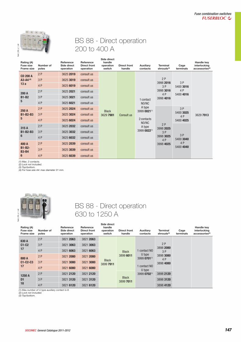
147General Catalogue 2011-2012SOCOMEC 147
Fuse combination switchesFUSERBLOC
Rating (A)Fuse sizeFrame size
Number of poles
ReferenceSide direct operation
ReferenceDirect front operation
Side direct handle
operation switch
Direct front handle
Auxiliary contacts
Terminal shrouds(3)
Cage terminals
Handle key interlocking
accessories(2)
CD 200 AA3-A4 (4)
13 a
2 P 3625 2019 consult us
Black3629 7901
Consult us
1 contact NO/NCA type
3999 0021(1)
2 contacts NO/NCA type
3999 0022(1)
2 P3998 2016
3 P3998 3016
4 P3998 4016
3 P5400 3016
4 P5400 4016
3629 7913
3 P 3625 3019 consult us
4 P 3625 6019 consult us
200 AB1-B25
2 P 3625 2021 consult us
3 P 3625 3021 consult us
4 P 3625 6021 consult us
250 AB1-B2-B35
2 P 3625 2024 consult us
2 P
3998 2025 3 P
3998 3025 4 P
3998 4025
3 P5400 3025
4 P5400 4025
3 P 3625 3024 consult us
4 P 3625 6024 consult us
315 AB1-B2-B36
2 P 3625 2032 consult us
3 P5400 3040
4 P5400 4040
3 P 3625 3032 consult us
4 P 3625 6032 consult us
400 AB1-B2-B3-B46
2 P 3625 2039 consult us
3 P 3625 3039 consult us
4 P 3625 6039 consult us
(1) Max. 2 contacts.(2) Lock not included.(3) Top/bottom.(4) For fuse size A4: max diameter 31 mm.
Rating (A)Fuse sizeFrame size
Number of poles
ReferenceSide direct operation
ReferenceDirect front operation
Side direct handle
operation switch
Direct front handle
Auxiliary contacts
Terminal shrouds(3)
Cage terminals
Handle key interlocking
accessories(2)
630 AC1-C217
2 P 3821 2063 3821 2063
Black3899 7911
Black3899 6011
1 contact NOU type
3999 0701(1)
1 contact NO U type
3999 0702(1)
2 P3898 2080
3 P3898 3080
4 P3898 4080
3 P 3821 3063 3821 3063
4 P 3821 6063 3821 6063
800 AC1-C2-C317
2 P 3821 2080 3821 2080
3 P 3821 3080 3821 3080
4 P 3821 6080 3821 6080
1250 AD118
2 P 3821 2120 3821 2120Black
3899 7011
3898 2120
3 P 3821 3120 3821 3120 3898 3120
4 P 3821 6120 3821 6120 3898 4120
BS 88 - Direct operation200 to 400 A
fuse
r_23
0_a_
1_ca
tfu
ser_
416_
a_1_
cat
BS 88 - Direct operation630 to 1250 A
(1) Max.number of U type auxiliary contact is 8.(2) Lock not included.(3) Top/bottom.
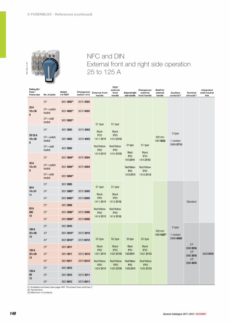
148 General Catalogue 2011-2012 SOCOMEC148
NFC and DINExternal front and right side operation25 to 125 A
FUSERBLOC - References (continued)
Rating (A) /Fuse /Frame size No. of poles
Switch I-0-TEST
Changeover switch I-0-II
External front handle
TEST external
fronthandle
External right side handle
Changeover external
front handle
Shaft for external handle
Auxiliary contacts(2)
Terminal shrouds(1)
Integrated solid neutral
link
25 A10 x 380
3 P 3631 3002(1) 3670 3002
S1 type
Black IP55
1411 2111
Red/Yellow IP65
1414 2111
S1 type
Black IP65
1413 2115
Red/Yellow IP65
1414 2115
S1 type
Black IP55
1415 2111
Red/YellowIP65
1418 2111
S1 type
Black IP55
1415 2113
Red/YellowIP65
1418 2113
320 mm1401 0532
U type
1 contact3999 0710
3 P + switch neutral
3631 4002(1) 3670 4002
3 P + solid neutral
3631 5002(1)
CD 32 A10 x 380
3 P 3631 3003 3670 3003
3 P + switch neutral
3631 4003 3670 4003
3 P + solid neutral
3631 5003
32 A14 x 510
3 P 3631 3004(1) 3670 3004
3 P + switch neutral
3631 4004(1) 3670 4004
3 P + solid neutral
3631 5004(1)
50 A14 x 5111
2 P 3831 2005 S1 type
Black IP65
1411 2111
Red/Yellow IP65
1414 2111
S1 type
Black IP65
1413 2115
Red/Yellow IP65
1414 2115
320 mm1400 1032(2)
U type
1 contact3999 0600
Standard
3 P 3831 3005(1) 3870 3005
4 P 3831 6005(1) 3870 6005
63 A00C12
2 P 3831 2006
3 P 3831 3006(1) 3870 3006
4 P 3831 6006(1) 3870 6006
100 A22 x 5813
2 P 3831 2010
S2 type
Black IP65
1421 2111
Red/Yellow IP65
1424 2111
S2 type
Black IP55
1423 2115
Red/Yellow IP65
1424 2115
S2 type
Black IP55
1425 2111
Red/Yellow IP65
1428 2111
S2 type
Black IP55
1421 2113
Red/Yellow IP65
1424 2113
2 P3998 2016
3 P3998 3016
4 P3998 4016
3829 9310
3 P 3831 3010(1) 3870 3010
4 P 3831 6010(1) 3870 6010
125 A22 x 5813
2 P 3831 2011
3 P 3831 3011 3870 3010
4 P 3831 6011 3870 6010
125 A0013
2 P 3831 2012
3 P 3831 3012 3870 3011
4 P 3831 6012 3870 6011
(1) Available enclosed (see page 494 "Enclosed fuse switches").(2) Top/bottom.(3) Maximum 4 contacts.
fuse
r_55
6_a_
2_ca
t
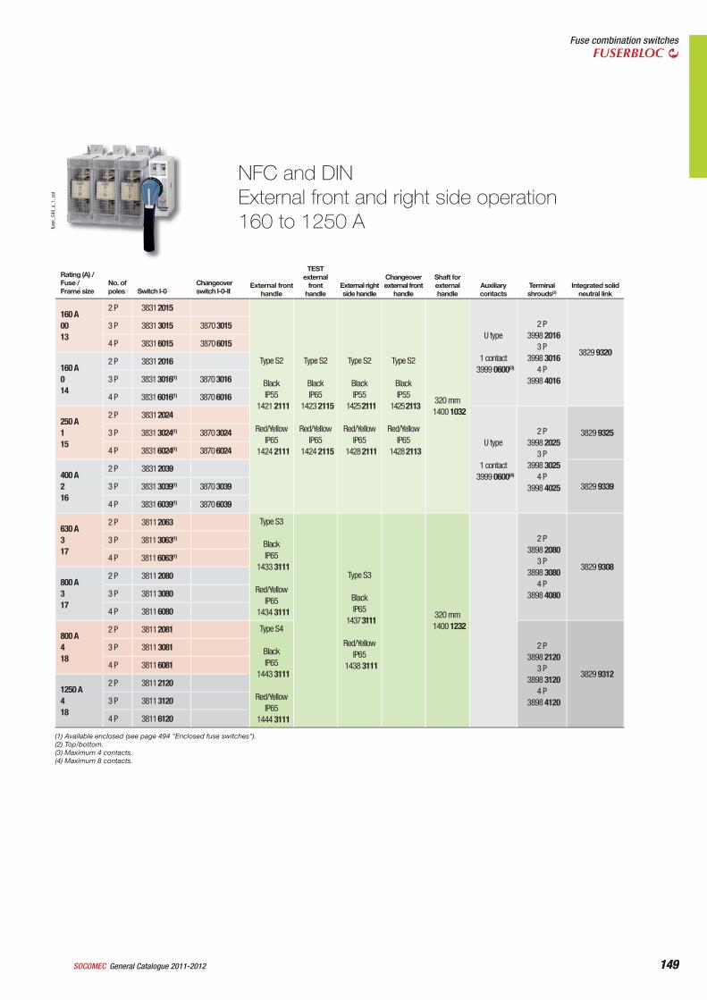
149General Catalogue 2011-2012SOCOMEC 149
Fuse combination switchesFUSERBLOC
fuse
r_54
8_a_
1_ca
t
NFC and DINExternal front and right side operation160 to 1250 A
Rating (A) /Fuse /Frame size
No. of poles Switch I-0
Changeover switch I-0-II
External front handle
TEST external
fronthandle
External right side handle
Changeover external front
handle
Shaft for external handle
Auxiliary contacts
Terminalshrouds(2)
Integrated solid neutral link
160 A0013
2 P 3831 2015
Type S2
Black IP55
1421 2111
Red/Yellow IP65
1424 2111
Type S2
Black IP65
1423 2115
Red/YellowIP65
1424 2115
Type S2
Black IP55
1425 2111
Red/Yellow IP65
1428 2111
Type S2
Black IP55
1425 2113
Red/Yellow IP65
1428 2113
320 mm1400 1032
U type
1 contact3999 0600(3)
2 P3998 2016
3 P3998 3016
4 P3998 4016
3829 9320
3 P 3831 3015 3870 3015
4 P 3831 6015 3870 6015
160 A014
2 P 3831 2016
3 P 3831 3016(1) 3870 3016
4 P 3831 6016(1) 3870 6016
250 A115
2 P 3831 2024
U type
1 contact3999 0600(4)
2 P3998 2025
3 P3998 3025
4 P3998 4025
3829 93253 P 3831 3024(1) 3870 3024
4 P 3831 6024(1) 3870 6024
400 A216
2 P 3831 2039
3829 93393 P 3831 3039(1) 3870 3039
4 P 3831 6039(1) 3870 6039
630 A317
2 P 3811 2063 Type S3
Black IP65
1433 3111
Red/Yellow IP65
1434 3111
Type S3
Black IP65
1437 3111
Red/Yellow IP65
1438 3111
320 mm1400 1232
2 P3898 2080
3 P3898 3080
4 P3898 4080
3829 9308
3 P 3811 3063(1)
4 P 3811 6063(1)
800 A317
2 P 3811 2080
3 P 3811 3080
4 P 3811 6080
800 A418
2 P 3811 2081 Type S4
Black IP65
1443 3111
Red/Yellow IP65
1444 3111
2 P3898 2120
3 P3898 3120
4 P3898 4120
3829 9312
3 P 3811 3081
4 P 3811 6081
1250 A418
2 P 3811 2120
3 P 3811 3120
4 P 3811 6120
(1) Available enclosed (see page 494 "Enclosed fuse switches").(2) Top/bottom.(3) Maximum 4 contacts.(4) Maximum 8 contacts.
150 General Catalogue 2011-2012 SOCOMEC150
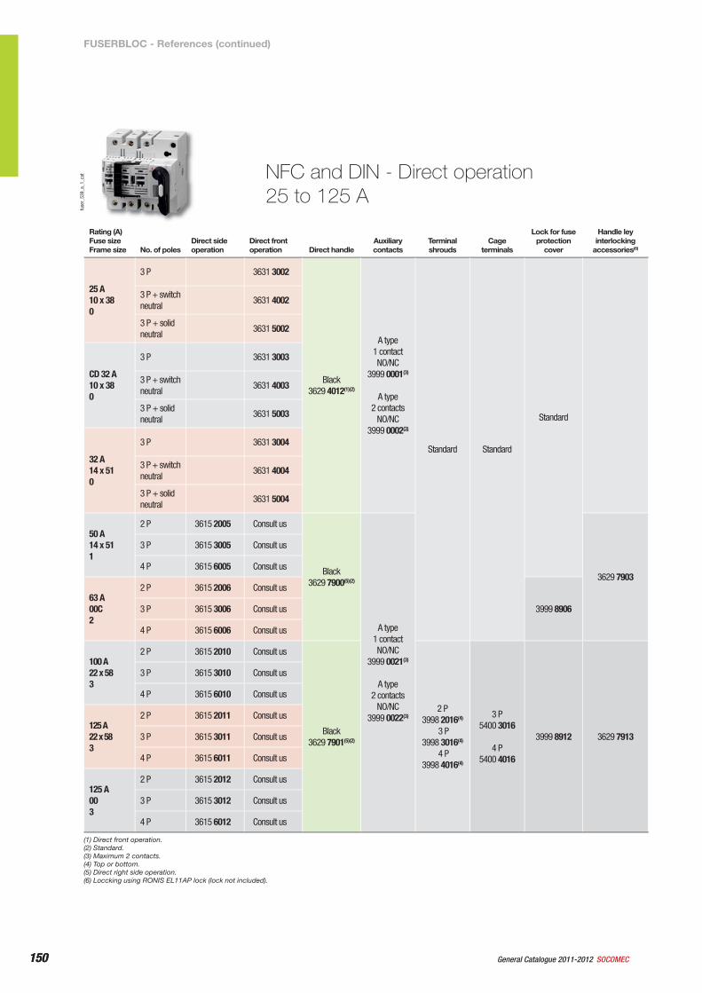
NFC and DIN - Direct operation25 to 125 A
fuse
r_53
9_a_
1_ca
t
Rating (A)Fuse sizeFrame size No. of poles
Direct side operation
Direct front operation Direct handle
Auxiliary contacts
Terminal shrouds
Cage terminals
Lock for fuse protection
cover
Handle ley interlocking
accessories(6)
25 A10 x 380
3 P 3631 3002
Black3629 4012(1)(2)
A type 1 contact NO/NC
3999 0001(3)
A type
2 contacts NO/NC
3999 0002(3)
Standard Standard
Standard
3 P + switch neutral
3631 4002
3 P + solid neutral
3631 5002
CD 32 A10 x 380
3 P 3631 3003
3 P + switch neutral
3631 4003
3 P + solid neutral
3631 5003
32 A14 x 510
3 P 3631 3004
3 P + switch neutral
3631 4004
3 P + solid neutral
3631 5004
50 A14 x 511
2 P 3615 2005 Consult us
Black3629 7900(5)(2)
A type 1 contact NO/NC
3999 0021(3)
A type
2 contacts NO/NC
3999 0022(3)
3629 7903
3 P 3615 3005 Consult us
4 P 3615 6005 Consult us
63 A00C2
2 P 3615 2006 Consult us
3999 89063 P 3615 3006 Consult us
4 P 3615 6006 Consult us
100 A22 x 583
2 P 3615 2010 Consult us
Black3629 7901(5)(2)
2 P3998 2016(4)
3 P3998 3016(4)
4 P3998 4016(4)
3 P5400 3016
4 P5400 4016
3999 8912 3629 7913
3 P 3615 3010 Consult us
4 P 3615 6010 Consult us
125 A22 x 583
2 P 3615 2011 Consult us
3 P 3615 3011 Consult us
4 P 3615 6011 Consult us
125 A003
2 P 3615 2012 Consult us
3 P 3615 3012 Consult us
4 P 3615 6012 Consult us
(1) Direct front operation.(2) Standard.(3) Maximum 2 contacts.(4) Top or bottom.(5) Direct right side operation.(6) Loccking using RONIS EL11AP lock (lock not included).
FUSERBLOC - References (continued)
151General Catalogue 2011-2012SOCOMEC 151
Fuse combination switchesFUSERBLOC
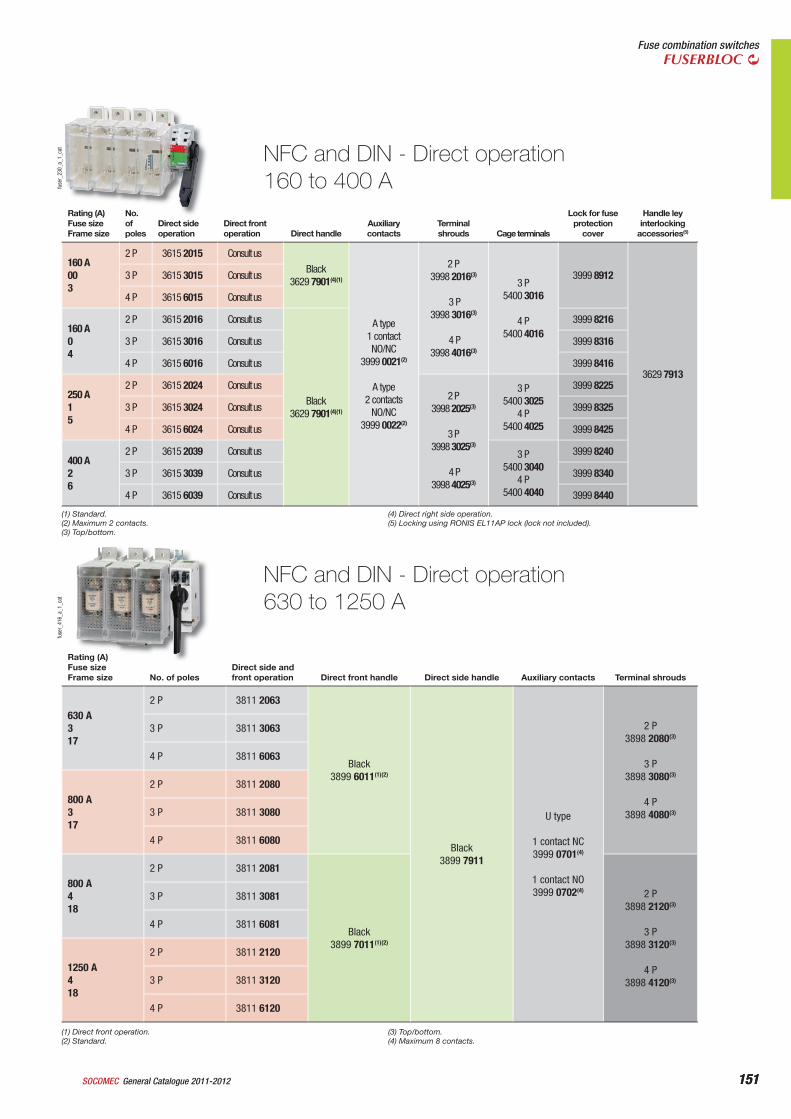
NFC and DIN - Direct operation160 to 400 Afu
ser_
230_
a_1_
cat
Rating (A)Fuse sizeFrame size
No. of poles
Direct side operation
Direct front operation Direct handle
Auxiliary contacts
Terminal shrouds Cage terminals
Lock for fuse protection
cover
Handle ley interlocking
accessories(5)
160 A003
2 P 3615 2015 Consult us
Black3629 7901(4)(1)
A type 1 contact NO/NC
3999 0021(2)
A type
2 contacts NO/NC
3999 0022(2)
2 P3998 2016(3)
3 P3998 3016(3)
4 P3998 4016(3)
3 P5400 3016
4 P5400 4016
3999 8912
3629 7913
3 P 3615 3015 Consult us
4 P 3615 6015 Consult us
160 A04
2 P 3615 2016 Consult us
Black3629 7901(4)(1)
3999 8216
3 P 3615 3016 Consult us 3999 8316
4 P 3615 6016 Consult us 3999 8416
250 A15
2 P 3615 2024 Consult us2 P
3998 2025(3)
3 P3998 3025(3)
4 P3998 4025(3)
3 P5400 3025
4 P5400 4025
3999 8225
3 P 3615 3024 Consult us 3999 8325
4 P 3615 6024 Consult us 3999 8425
400 A26
2 P 3615 2039 Consult us 3 P5400 3040
4 P5400 4040
3999 8240
3 P 3615 3039 Consult us 3999 8340
4 P 3615 6039 Consult us 3999 8440
NFC and DIN - Direct operation630 to 1250 A
fuse
r_41
6_a_
1_ca
t
Rating (A)Fuse sizeFrame size No. of poles
Direct side and front operation Direct front handle Direct side handle Auxiliary contacts Terminal shrouds
630 A317
2 P 3811 2063
Black3899 6011(1)(2)
Black3899 7911
U type
1 contact NC3999 0701(4)
1 contact NO3999 0702(4)
2 P3898 2080(3)
3 P
3898 3080(3)
4 P
3898 4080(3)
3 P 3811 3063
4 P 3811 6063
800 A317
2 P 3811 2080
3 P 3811 3080
4 P 3811 6080
800 A418
2 P 3811 2081
Black3899 7011(1)(2)
2 P3898 2120(3)
3 P
3898 3120(3)
4 P
3898 4120(3)
3 P 3811 3081
4 P 3811 6081
1250 A418
2 P 3811 2120
3 P 3811 3120
4 P 3811 6120
(1) Direct front operation.(2) Standard.
(3) Top/bottom.(4) Maximum 8 contacts.
(1) Standard.(2) Maximum 2 contacts.(3) Top/bottom.
(4) Direct right side operation.(5) Locking using RONIS EL11AP lock (lock not included).
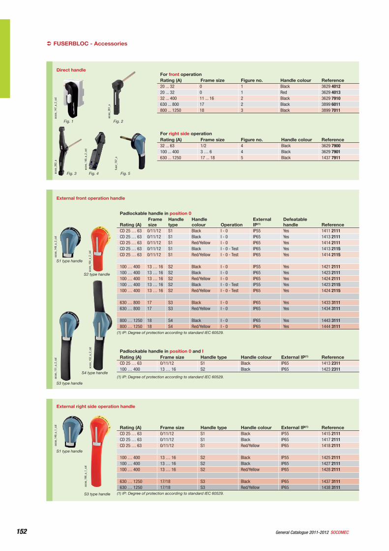
152 General Catalogue 2011-2012 SOCOMEC152
External right side operation handle
acce
s_16
6_a_
1_ca
t
S3 type handle
acce
s_14
9_a_
1_ca
t
S1 type handle
Rating (A) Frame size Handle type Handle colour External IP(1) ReferenceCD 25 … 63 0/11/12 S1 Black IP55 1415 2111CD 25 … 63 0/11/12 S1 Black IP65 1417 2111CD 25 … 63 0/11/12 S1 Red/Yellow IP65 1418 2111
100 … 400 13 … 16 S2 Black IP55 1425 2111100 … 400 13 … 16 S2 Black IP65 1427 2111100 … 400 13 … 16 S2 Red/Yellow IP65 1428 2111
630 … 1250 17/18 S3 Black IP65 1437 3111630 … 1250 17/18 S3 Red/Yellow IP65 1438 3111
(1) IP: Degree of protection according to standard IEC 60529.
FUSERBLOC - Accessories‹
External front operation handle
acce
s_15
2_a_
2_ca
t
S4 type handle
acce
s_15
1_a_
2_ca
t
S3 type handle
acce
s_16
4_a_
2_ca
t
S2 type handle
acce
s_14
9_a_
2_ca
t
S1 type handle
Padlockable handle in position 0
Rating (A)Frame size
Handle type
Handle colour Operation
External IP(1)
Defeatable handle Reference
CD 25 … 63 0/11/12 S1 Black I - 0 IP55 Yes 1411 2111CD 25 … 63 0/11/12 S1 Black I - 0 IP65 Yes 1413 2111CD 25 … 63 0/11/12 S1 Red/Yellow I - 0 IP65 Yes 1414 2111CD 25 … 63 0/11/12 S1 Black I - 0 - Test IP65 Yes 1413 2115CD 25 … 63 0/11/12 S1 Red/Yellow I - 0 - Test IP65 Yes 1414 2115
100 … 400 13 … 16 S2 Black I - 0 IP55 Yes 1421 2111100 … 400 13 … 16 S2 Black I - 0 IP65 Yes 1423 2111100 … 400 13 … 16 S2 Red/Yellow I - 0 IP65 Yes 1424 2111100 … 400 13 … 16 S2 Black I - 0 - Test IP55 Yes 1423 2115100 … 400 13 … 16 S2 Red/Yellow I - 0 - Test IP65 Yes 1424 2115
630 … 800 17 S3 Black I - 0 IP65 Yes 1433 3111630 … 800 17 S3 Red/Yellow I - 0 IP65 Yes 1434 3111
800 … 1250 18 S4 Black I - 0 IP65 Yes 1443 3111800 … 1250 18 S4 Red/Yellow I - 0 IP65 Yes 1444 3111
(1) IP: Degree of protection according to standard IEC 60529.
Padlockable handle in position 0 and IRating (A) Frame size Handle type Handle colour External IP(1) ReferenceCD 25 … 63 0/11/12 S1 Black IP65 1413 2311100 … 400 13 … 16 S2 Black IP65 1423 2311
(1) IP: Degree of protection according to standard IEC 60529.
Direct handle
acce
s_26
1_a
acce
s_14
7_a_
2_ca
t
For front operationRating (A) Frame size Figure no. Handle colour Reference20 ... 32 0 1 Black 3629 401220 ... 32 0 1 Red 3629 401332 ... 400 11 ... 16 2 Black 3629 7910630 ... 800 17 2 Black 3899 6011800 ... 1250 18 3 Black 3899 7011
For right side operationRating (A) Frame size Figure no. Handle colour Reference32 ... 63 1/2 4 Black 3629 7900100 ... 400 3 … 6 4 Black 3629 7901630 ... 1250 17 ... 18 5 Black 1437 7911
acce
s_26
2_a
acce
s_14
8_a_
2_ca
t
fuse
r_70
7_a
Fig. 1 Fig. 2
Fig. 3 Fig. 4 Fig. 5
153General Catalogue 2011-2012SOCOMEC 153
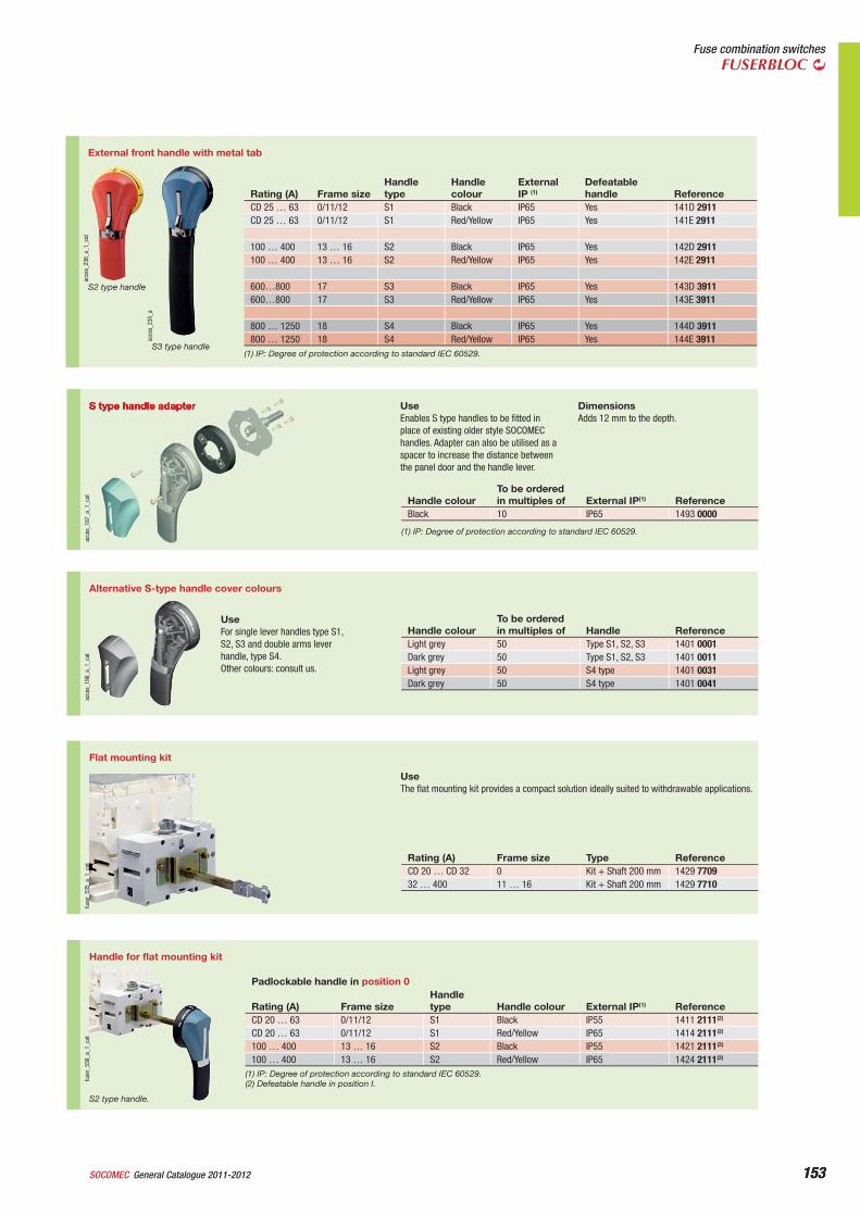
Fuse combination switchesFUSERBLOC
acce
s_23
6_a_
1_ca
t
S2 type handle
acce
s_23
5_a
S3 type handle
External front handle with metal tab
Rating (A) Frame sizeHandle type
Handle colour
External IP (1)
Defeatable handle Reference
CD 25 … 63 0/11/12 S1 Black IP65 Yes 141D 2911CD 25 … 63 0/11/12 S1 Red/Yellow IP65 Yes 141E 2911
100 … 400 13 … 16 S2 Black IP65 Yes 142D 2911100 … 400 13 … 16 S2 Red/Yellow IP65 Yes 142E 2911
600…800 17 S3 Black IP65 Yes 143D 3911600…800 17 S3 Red/Yellow IP65 Yes 143E 3911
800 … 1250 18 S4 Black IP65 Yes 144D 3911800 … 1250 18 S4 Red/Yellow IP65 Yes 144E 3911
(1) IP: Degree of protection according to standard IEC 60529.
S type handle adapter
acce
s_18
7_a_
1_ca
t
UseEnables S type handles to be fitted in place of existing older style SOCOMEC handles. Adapter can also be utilised as a spacer to increase the distance between the panel door and the handle lever.
DimensionsAdds 12 mm to the depth.
Handle colourTo be orderedin multiples of External IP(1) Reference
Black 10 IP65 1493 0000
(1) IP: Degree of protection according to standard IEC 60529.
Alternative S-type handle cover colours
acce
s_19
8_a_
1_ca
t
UseFor single lever handles type S1, S2, S3 and double arms lever handle, type S4.Other colours: consult us.
Handle colourTo be orderedin multiples of Handle Reference
Light grey 50 Type S1, S2, S3 1401 0001Dark grey 50 Type S1, S2, S3 1401 0011Light grey 50 S4 type 1401 0031Dark grey 50 S4 type 1401 0041
Flat mounting kit
fuse
r_53
5_a_
1_ca
t
UseThe flat mounting kit provides a compact solution ideally suited to withdrawable applications.
Rating (A) Frame size Type ReferenceCD 20 … CD 32 0 Kit + Shaft 200 mm 1429 770932 … 400 11 … 16 Kit + Shaft 200 mm 1429 7710
Handle for flat mounting kit
fuse
r_53
6_a_
1_ca
t
S2 type handle.
Padlockable handle in position 0
Rating (A) Frame sizeHandle type Handle colour External IP(1) Reference
CD 20 … 63 0/11/12 S1 Black IP55 1411 2111(2)
CD 20 … 63 0/11/12 S1 Red/Yellow IP65 1414 2111(2)
100 … 400 13 … 16 S2 Black IP55 1421 2111(2)
100 … 400 13 … 16 S2 Red/Yellow IP65 1424 2111(2)
(1) IP: Degree of protection according to standard IEC 60529.(2) Defeatable handle in position I.
154 General Catalogue 2011-2012 SOCOMEC154
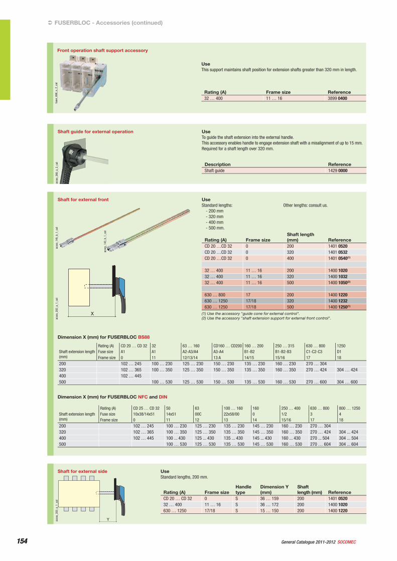
Shaft guide for external operation
acce
s_26
0_a_
2_ca
t
UseTo guide the shaft extension into the external handle.This accessory enables handle to engage extension shaft with a misalignment of up to 15 mm.Required for a shaft length over 320 mm.
Description ReferenceShaft guide 1429 0000
FUSERBLOC - Accessories (continued)‹
Shaft for external front
X
acce
s_20
2_a_
1_ca
t
acce
s_14
3_b_
1_ca
t
acce
s_14
5_b_
1_ca
t
UseStandard lengths:
- 200 mm- 320 mm- 400 mm- 500 mm.
Other lengths: consult us.
Rating (A) Frame sizeShaft length (mm) Reference
CD 20 …CD 32 0 200 1401 0520CD 20 …CD 32 0 320 1401 0532CD 20 …CD 32 0 400 1401 0540(1)
32 … 400 11 … 16 200 1400 102032 … 400 11 … 16 320 1400 103232 … 400 11 … 16 500 1400 1050(2)
630 … 800 17 200 1400 1220630 … 1250 17/18 320 1400 1232630 … 1250 17/18 500 1400 1250(1)
(1) Use the accessory "guide cone for external control".(2) Use the accessory "shaft extension support for external front control".
Dimension X (mm) for FUSERBLOC NFC and DIN
Rating (A) CD 25 … CD 32 50 63 100 … 160 160 250 … 400 630 … 800 800 … 1250Shaft extension length (mm)
Fuse size 10x38/14x51 14x51 00C 22x58/00 0 1/2 3 4Frame size 0 11 12 13 14 15/16 17 18
200 102 … 245 100 … 230 125 … 230 135 … 230 145 … 230 160 … 230 270 … 304320 102 … 365 100 … 350 125 … 350 135 … 350 145 … 350 160 … 350 270 … 424 304 ... 424400 102 … 445 100 ... 430 125 ... 430 135 ... 430 145 ... 430 160 ... 430 270 ... 504 304 ... 504500 100 … 530 125 … 530 135 … 530 145 … 530 160 … 530 270 … 604 304 ... 604
Dimension X (mm) for FUSERBLOC BS88
Rating (A) CD 20 … CD 32 32 63 … 160 CD160 … CD200 160 … 200 250 … 315 630 … 800 1250Shaft extension length (mm)
Fuse size A1 A1 A2-A3/A4 A3-A4 B1-B2 B1-B2-B3 C1-C2-C3 D1Frame size 0 11 12/13/14 13 A 14/15 15/16 17 18
200 102 … 245 100 … 230 125 … 230 150 … 230 135 … 230 160 … 230 270 … 304320 102 … 365 100 … 350 125 … 350 150 … 350 135 … 350 160 … 350 270 … 424 304 … 424400 102 … 445500 100 … 530 125 … 530 150 … 530 135 … 530 160 … 530 270 … 600 304 … 600
Shaft for external side
Yacce
s_20
3_a_
1_ca
t
UseStandard lengths, 200 mm.
Rating (A) Frame sizeHandle type
Dimension Y (mm)
Shaftlength (mm) Reference
CD 20 … CD 32 0 S 36 … 159 200 1401 052032 … 400 11 … 16 S 36 … 172 200 1400 1020630 … 1250 17/18 S 15 … 150 200 1400 1220
Front operation shaft support accessoryfu
ser_
698_
a_2_
cat
UseThis support maintains shaft position for extension shafts greater than 320 mm in length.
Rating (A) Frame size Reference32 … 400 11 … 16 3899 0400
155General Catalogue 2011-2012SOCOMEC 155
Fuse combination switchesFUSERBLOC
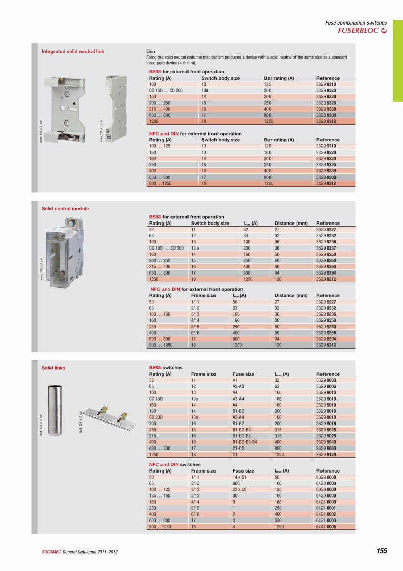
Integrated solid neutral link
acce
s_13
1_a_
1_ca
t
acce
s_13
0_a_
1_ca
t
UseFixing the solid neutral onto the mechanism produces a device with a solid neutral of the same size as a standard three-pole device (+ 6 mm).
NFC and DIN for external front operationRating (A) Switch body size Bar rating (A) Reference100 … 125 13 125 3829 9310160 13 160 3829 9320160 14 200 3829 9320250 15 250 3829 9325400 16 400 3829 9339630 … 800 17 800 3829 9308800 …1250 18 1250 3829 9312
BS88 for external front operationRating (A) Switch body size Bar rating (A) Reference100 13 125 3829 9310CD 160 … CD 200 13a 200 3829 9320160 14 200 3829 9320200 … 250 15 250 3829 9325315 … 400 16 400 3829 9339630 … 800 17 800 3829 93081250 18 1250 3829 9312
Solid neutral module
acce
s_19
9_a_
2_ca
t
NFC and DIN for external front operationRating (A) Frame size Imax(A) Distance (mm) Reference50 1/11 50 27 3629 922763 2/12 63 32 3629 9232100 … 160 3/13 160 36 3629 9236160 4/14 160 50 3629 9250250 5/15 250 60 3629 9260400 6/16 400 60 3629 9266630 … 800 17 800 94 3629 9294800 … 1250 18 1250 120 3629 9212
BS88 for external front operationRating (A) Switch body size Imax (A) Distance (mm) Reference32 11 32 27 3629 922763 12 63 32 3629 9232100 13 100 36 3629 9236CD 160 … CD 200 13 a 200 36 3629 9237160 14 160 50 3629 9250200 … 250 15 250 60 3629 9260315 … 400 16 400 66 3629 9266630 … 800 17 800 94 3629 92941250 18 1250 120 3629 9212
Solid links
fusi
b_12
4_a_
2_ca
t
fusi
b_12
3_a_
2_ca
t
NFC and DIN switchesRating (A) Frame size Fuse size Imax (A) Reference50 1/11 14 x 51 50 6029 000063 2/12 00C 160 6420 0000100 … 125 3/13 22 x 58 125 6039 0000125 … 160 3/13 00 160 6420 0000160 4/14 0 160 6421 0000250 5/15 1 250 6421 0001400 6/16 2 400 6421 0002630 … 800 17 3 630 6421 0003800 ... 1250 18 4 1250 6441 0005
BS88 switchesRating (A) Frame size Fuse size Imax (A) Reference32 11 A1 32 3629 900363 12 A2-A3 63 3629 9006100 13 A4 160 3629 9010CD 160 13a A3-A4 160 3629 9010160 14 A4 160 3629 9010160 14 B1-B2 200 3629 9016CD 200 13a A3-A4 160 3629 9010200 15 B1-B2 200 3629 9016250 15 B1-B2-B3 315 3629 9025315 16 B1-B2-B3 315 3629 9025400 16 B1-B2-B3-B4 400 3629 9040630 … 800 17 C1-C3 800 3629 90631250 18 D1 1250 3629 9120
156 General Catalogue 2011-2012 SOCOMEC156
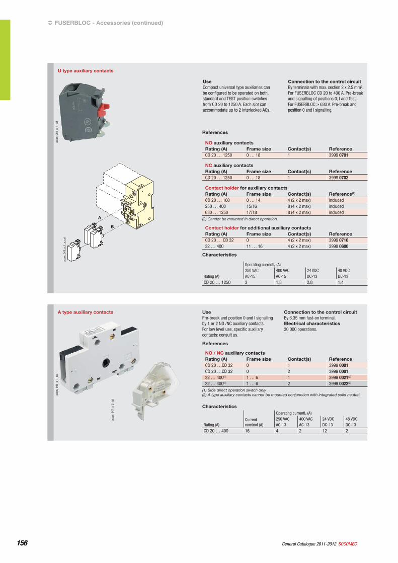
U type auxiliary contacts
A
B
acce
s_05
6_a_
1_ca
t
acce
s_04
3_a_
1_x_
cat
UseCompact universal type auxiliaries can be configured to be operated on both, standard and TEST position switches from CD 20 to 1250 A. Each slot can accommodate up to 2 interlocked ACs.
Connection to the control circuitBy terminals with max. section 2 x 2.5 mm².For FUSERBLOC CD 20 to 400 A. Pre-break and signalling of positions 0, I and Test.For FUSERBLOC ≥ 630 A: Pre-break and position 0 and I signalling.
References
NO auxiliary contactsRating (A) Frame size Contact(s) ReferenceCD 20 … 1250 0 … 18 1 3999 0701
NC auxiliary contactsRating (A) Frame size Contact(s) ReferenceCD 20 … 1250 0 … 18 1 3999 0702
Contact holder for auxiliary contactsRating (A) Frame size Contact(s) Reference(2)
CD 20 … 160 0 … 14 4 (2 x 2 max) included250 … 400 15/16 8 (4 x 2 max) included630 … 1250 17/18 8 (4 x 2 max) included
(2) Cannot be mounted in direct operation.
Contact holder for additional auxiliary contactsRating (A) Frame size Contact(s) ReferenceCD 20 … CD 32 0 4 (2 x 2 max) 3999 071032 … 400 11 … 16 4 (2 x 2 max) 3999 0600
Characteristics
Operating currentIe (A)250 VAC 400 VAC 24 VDC 48 VDC
Rating (A) AC-15 AC-15 DC-13 DC-13CD 20 … 1250 3 1.8 2.8 1.4
A type auxiliary contacts
acce
s_04
6_a_
1_ca
t
acce
s_04
7_a_
2_ca
t
UsePre-break and position 0 and I signalling by 1 or 2 NO /NC auxiliary contacts.For low level use, specific auxiliary contacts: consult us.
Connection to the control circuitBy 6.35 mm fast-on terminal.Electrical characteristics30 000 operations.
References
NO / NC auxiliary contactsRating (A) Frame size Contact(s) ReferenceCD 20 …CD 32 0 1 3999 0001CD 20 …CD 32 0 2 3999 000132 … 400(1) 1 … 6 1 3999 0021(2)
32 … 400(1) 1 … 6 2 3999 0022(2)
(1) Side direct operation switch only.(2) A type auxiliary contacts cannot be mounted conjunction with integrated solid neutral.
Characteristics
Rating (A)Currentnominal (A)
Operating currentIe (A)250 VAC 400 VAC 24 VDC 48 VDCAC-13 AC-13 DC-13 DC-13
CD 20 … 400 16 4 2 12 2
FUSERBLOC - Accessories (continued)‹
157General Catalogue 2011-2012SOCOMEC 157
Fuse combination switchesFUSERBLOC
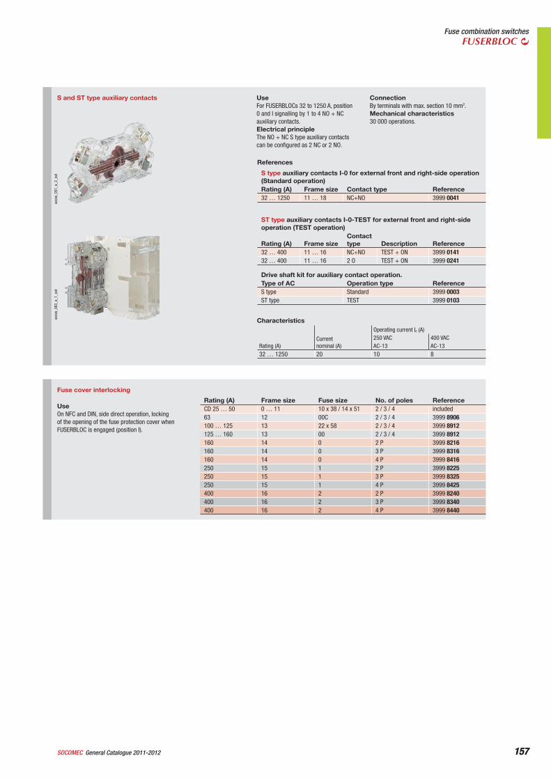
S and ST type auxiliary contacts
acce
s_05
1_a_
2_ca
tac
ces_
083_
a_1_
cat
UseFor FUSERBLOCs 32 to 1250 A, position 0 and I signalling by 1 to 4 NO + NC auxiliary contacts.Electrical principleThe NO + NC S type auxiliary contacts can be configured as 2 NC or 2 NO.
ConnectionBy terminals with max. section 10 mm2.Mechanical characteristics30 000 operations.
References
S type auxiliary contacts I-0 for external front and right-side operation (Standard operation)Rating (A) Frame size Contact type Reference32 … 1250 11 … 18 NC+NO 3999 0041
ST type auxiliary contacts I-0-TEST for external front and right-side operation (TEST operation)
Rating (A) Frame sizeContact type Description Reference
32 … 400 11 … 16 NC+NO TEST + ON 3999 014132 … 400 11 … 16 2 O TEST + ON 3999 0241
Drive shaft kit for auxiliary contact operation.Type of AC Operation type ReferenceS type Standard 3999 0003ST type TEST 3999 0103
Characteristics
Rating (A)Currentnominal (A)
Operating current Ie (A)250 VAC 400 VACAC-13 AC-13
32 … 1250 20 10 8
Fuse cover interlocking
UseOn NFC and DIN, side direct operation, locking of the opening of the fuse protection cover when FUSERBLOC is engaged (position I).
Rating (A) Frame size Fuse size No. of poles ReferenceCD 25 … 50 0 … 11 10 x 38 / 14 x 51 2 / 3 / 4 included63 12 00C 2 / 3 / 4 3999 8906100 … 125 13 22 x 58 2 / 3 / 4 3999 8912125 … 160 13 00 2 / 3 / 4 3999 8912160 14 0 2 P 3999 8216160 14 0 3 P 3999 8316160 14 0 4 P 3999 8416250 15 1 2 P 3999 8225250 15 1 3 P 3999 8325250 15 1 4 P 3999 8425400 16 2 2 P 3999 8240400 16 2 3 P 3999 8340400 16 2 4 P 3999 8440
158 General Catalogue 2011-2012 SOCOMEC158
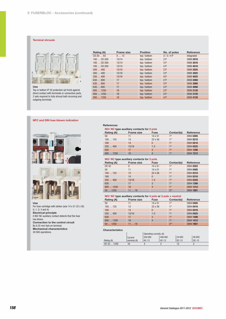
NFC and DIN fuse blowm indication
fuse
r_31
2_a_
1_ca
tfu
ser_
311_
a_1_
cat
UseFor fuse cartridge with striker (size 14 x 51 22 x 58; 0; 1; 2; 3 and 4).Electrical principleA NO/ NC auxiliary contact detects that the fuse has blown.Connection to the control circuitBy 6.35 mm fast-on terminal.Mechanical characteristics30 000 operations.
ReferencesNO/ NC type auxiliary contacts for 2 poleRating (A) Frame size Fuse Contact(s) Reference50 11 14 x 51 1st 3994 0405100 … 125 13 22 x 58 1st 3994 0210160 14 0 1st 3994 0216250 … 400 15/16 1-2 1st 3994 0225630 17 3 1st 3894 1206800 … 1250 18 4 1st 3894 1212
NO/ NC type auxiliary contacts for 3 poleRating (A) Frame size Fuse Contact(s) ReferenceCD 32 0 14 x 51 1st 3994 030350 11 14 x 51 1st 3994 0405100 … 125 13 22 x 58 1st 3994 0310160 14 0 1st 3994 0316250 … 400 15/16 1-2 1st 3994 0325630 17 3 1st 3894 1306800 … 1250 18 4 1st 3894 131250 … 1250 11 … 18 2nd 3994 1901
NO/ NC type auxiliary contacts for 4 pole or 3 pole + neutralRating (A) Frame size Fuse Contact(s) Reference50 11 14 x 51 1st 3994 0405100 … 125 13 22 x 58 1st 3994 0410160 14 0 1st 3994 0416250 … 400 15/16 1-2 1st 3994 0425630 17 3 1st 3894 1406800 … 1250 18 4 1st 3894 141250 … 1250 11 … 18 2nd 3994 1901
Characteristics
Rating (A)Currentnominal (A)
Operating currentIe (A)250 VAC 400 VAC 24 VDC 48 VDCAC-13 AC-13 DC-13 DC-13
CD 32 ... 1250 16 4 3 12 2
FUSERBLOC - Accessories (continued)‹
Terminal shrouds
fuse
r_31
4_a_
1_ca
t
UseTop or bottom IP 20 protection (at front) against direct contact with terminals or connection parts.2 sets required to fully shroud both incoming and outgoing terminals.
Rating (A) Frame size Position No. of poles ReferenceCD 20 … 63 0 … 12 top / bottom 2 / 3 / 4 P integrated100 … CD 200 13/14 top / bottom 2 P 3998 2016100 … CD 200 13/14 top / bottom 3 P 3998 3016100 … CD 200 13/14 top / bottom 4 P 3998 4016200 … 400 15/16 top / bottom 2 P 3998 2025200 … 400 15/16 top / bottom 3 P 3998 3025200 … 400 15/16 top / bottom 4 P 3998 4025630 … 800 17 top / bottom 2 P 3898 2080630 … 800 17 top / bottom 3 P 3898 3080630 … 800 17 top / bottom 4 P 3898 4080800 … 1250 18 top / bottom 2 P 3898 2120800 … 1250 18 top / bottom 3 P 3898 3120800 … 1250 18 top / bottom 4 P 3898 4120
159General Catalogue 2011-2012SOCOMEC 159
Fuse combination switchesFUSERBLOC
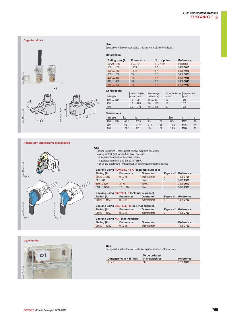
Label holder
acce
s_04
4_a_
1_ca
t
UseRecognisable self-adhesive label allowing identification of the devices.
Dimensions W x H (mm)To be orderedin multiples of Reference
18 x 13 50 7769 9999
Handle key interlocking accessories
acce
s_15
7_a_
1_x_
cat
Fig. 3
acce
s_15
8_a_
1_x_
cat
Fig. 2
acce
s_04
2_a_
1_x_
cat
Fig. 1
UseLocking in position 0 of the direct, front or right side operation:• using padlock (not supplied) in direct operation:- integrated into the handle of 20 to 400 A,- integrated into the frame of 630 to 1250 A.
• using key interlocking (not supplied) in external operation (see below).
Locking using RONIS EL 11 AP lock (not supplied)Rating (A) Frame size Operation Figure n° ReferenceCD 20 ... 1250 0 … 18 external front 2 1499 770132 … 63 1/2 direct 1 3629 7903100 … 400 3…6 direct 1 3629 7913630 … 1250 17 … 18 direct 3829 7923
Locking using CASTELL K lock (not supplied)Rating (A) Frame size Operation Figure n° ReferenceCD 20 … 1250 0 … 18 external front 3 1499 7702
Locking using CASTELL FS lock (not supplied)Rating (A) Frame size Operation Figure n° ReferenceCD 20 … 1250 0 … 18 external front 3 1499 7703
Locking using XOP (not included)Rating (A) Frame size Operation ReferenceCD 20 … 1250 0 … 18 external front 1499 7702
Cage terminals
A1
X1
øX
ZC
A
R
acce
s_09
2_a_
1_x_
cat
acce
s_09
1_a_
1_x_
cat
acce
s_05
3_a_
1_ca
t
UseConnection of bare copper cables onto the terminals (without lugs).
References Rating max (A) Frame size No. of poles ReferenceCD 20 … 63 0 … 12 2 / 3 / 4 P integrated100 … 160 13/14 3 P 5400 3016100 … 160 13/14 4 P 5400 4016200 … 250 15 3 P 5400 3025200 … 250 15 4 P 5400 4025315 … 400 16 3 P 5400 3040315 … 400 16 4 P 5400 4040
Connections
Rating (A)Section flexible cable (mm2)
Section rigid cable (mm2)
Width flexible bar (mm)
Stripped over (mm)
100 … 160 16 … 95 16 … 95 13 22250 16 … 185 16 … 185 18 27400 50 … 240 50 … 300 20 34
Dimensions
Rating (A) A A1 C R ØX X1 Z100 … 160 47.5 22.5 25 20 8.5 M12 10250 62 31.5 31.5 25 10.5 M16 14400 71.5 32 38 32 10.5 M20 15
160 General Catalogue 2011-2012 SOCOMEC160
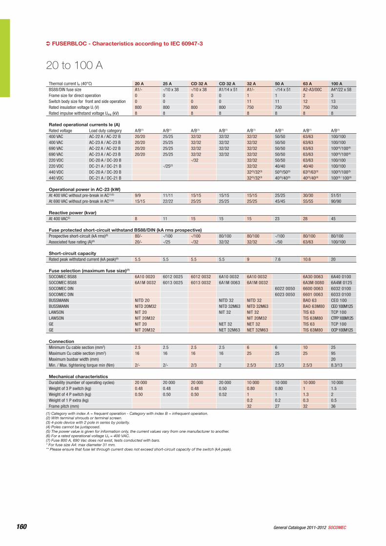
FUSERBLOC - Characteristics according to IEC 60947-3
Thermal current Ith (40°C) 20 A 25 A CD 32 A CD 32 A 32 A 50 A 63 A 100 ABS88/DIN fuse size A1/- -/10 x 38 -/10 x 38 A1/14 x 51 A1/- -/14 x 51 A2-A3/00C A4*/22 x 58Frame size for direct operation 0 0 0 0 1 1 2 3Switch body size for front and side operation 0 0 0 0 11 11 12 13Rated insulation voltage Ui (V) 800 800 800 800 750 750 750 750Rated impulse withstand voltage Uimp (kV) 8 8 8 8 8 8 8 8
Rated operational currents Ie (A) Rated voltage Load duty category A/B(1) A/B(1) A/B(1) A/B(1) A/B(1) A/B(1) A/B(1) A/B(1)
400 VAC AC-22 A / AC-22 B 20/20 25/25 32/32 32/32 32/32 50/50 63/63 100/100400 VAC AC-23 A / AC-23 B 20/20 25/25 32/32 32/32 32/32 50/50 63/63 100/100690 VAC AC-22 A / AC-22 B 20/20 25/25 32/32 32/32 32/32 50/50 63/63 100(4)/100(4)
690 VAC AC-23 A / AC-23 B 20/20 25/25 32/32 32/32 32/32 50/50 63/63 100(4)/100(4)
220 VDC DC-20 A / DC-20 B -/32 32/32 50/50 63/63 100/100220 VDC DC-21 A / DC-21 B -/25(2) 32/32 40/40 40/40 100/100440 VDC DC-20 A / DC-20 B 32(3)/32(3) 50(3)/50(3) 63(3)/63(3) 100(3)/100(3)
440 VDC DC-21 A / DC-21 B 32(3)/32(3) 40(3)/40(3) 40(3)/40(3) 100(3) / 100(3)
Operational power in AC-23 (kW) At 400 VAC without pre-break in AC(1)(5) 9/9 11/11 15/15 15/15 15/15 25/25 30/30 51/51At 690 VAC without pre-break in AC(1)(5) 15/15 22/22 25/25 25/25 25/25 45/45 55/55 90/90
Reactive power (kvar) At 400 VAC(5) 8 11 15 15 15 23 28 45
Fuse protected short-circuit withstand BS88/DIN (kA rms prospective)Prospective short-circuit (kA rms)(6) 80/- -/100 -/100 80/100 80/100 -/100 80/100 80/100Associated fuse rating (A)(6) 20/- -/25 -/32 32/32 32/32 -/50 63/63 100/100
Short-circuit capacityRated peak withstand current (kA peak)(6) 5.5 5.5 5.5 5.5 9 7.6 10.6 20
Fuse selection (maximum fuse size)(7)
SOCOMEC BS88 6A10 0020 6012 0025 6012 0032 6A10 0032 6A10 0032 6A30 0063 6A40 0100SOCOMEC BS88 6A1M 0032 6013 0025 6013 0032 6A1M 0063 6A1M 0032 6A3M 0080 6A4M 0125SOCOMEC DIN 6022 0050 6600 0063 6032 0100SOCOMEC DIN 6023 0050 6601 0063 6033 0100BUSSMANN NITD 20 NITD 32 NITD 32 BAO 63 CEO 100BUSSMANN NITD 20M32 NITD 32M63 NITD 32M63 BAO 63M80 CEO 100M125LAWSON NIT 20 NIT 32 NIT 32 TIS 63 TCP 100LAWSON NIT 20M32 NIT 20M32 TIS 63M80 CTFP 100M125GE NIT 20 NET 32 NET 32 TIS 63 TCP 100GE NIT 20M32 NET 32M63 NET 32M63 TIS 63M80 OCP 100M125
ConnectionMinimum Cu cable section (mm2) 2.5 2.5 2.5 2.5 6 6 10 25Maximum Cu cable section (mm2) 16 16 16 16 25 25 25 95Maximum busbar width (mm) 20Min. / Max. tightening torque min (Nm) 2/- 2/- 2/3 2 2.5/3 2.5/3 2.5/3 8.3/13
Mechanical characteristicsDurability (number of operating cycles) 20 000 20 000 20 000 20 000 10 000 10 000 10 000 10 000Weight of 3 P switch (kg) 0.48 0.48 0.48 0.50 0.80 0.80 1 1.5Weight of 4 P switch (kg) 0.50 0.50 0.50 0.52 1 1 1.3 2Weight of 1 P extra (kg) 0.2 0.2 0.3 0.5Frame pitch (mm) 32 27 32 36
20 to 100 A
(1) Category with index A = frequent operation - Category with index B = infrequent operation.(2) With terminal shrouds or terminal screen.(3) 4-pole device with 2 pole in series by polarity.(4) Poles cannot be juxtaposed.(5) The power value is given for information only, the current values vary from one manufacturer to another.(6) For a rated operational voltage Ue = 400 VAC.(7) Fuse 800 A, 690 Vac does not exist, tests conducted with bars.* For fuse size A4: max diameter 31 mm.** Please ensure that fuse let through current does not exceed short-circuit capacity of the switch (kA peak).
161General Catalogue 2011-2012SOCOMEC 161
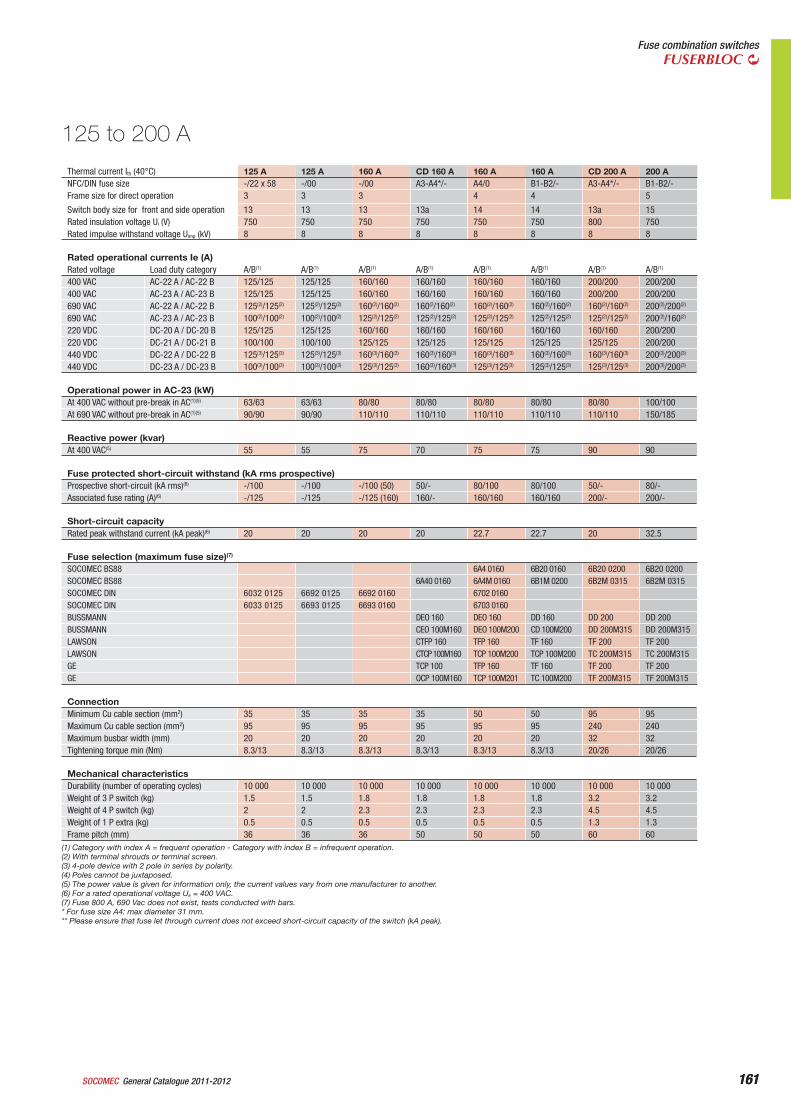
Fuse combination switchesFUSERBLOC
Thermal current Ith (40°C) 125 A 125 A 160 A CD 160 A 160 A 160 A CD 200 A 200 ANFC/DIN fuse size -/22 x 58 -/00 -/00 A3-A4*/- A4/0 B1-B2/- A3-A4*/- B1-B2/-Frame size for direct operation 3 3 3 4 4 5
Switch body size for front and side operation 13 13 13 13a 14 14 13a 15Rated insulation voltage Ui (V) 750 750 750 750 750 750 800 750Rated impulse withstand voltage Uimp (kV) 8 8 8 8 8 8 8 8
Rated operational currents Ie (A)Rated voltage Load duty category A/B(1) A/B(1) A/B(1) A/B(1) A/B(1) A/B(1) A/B(1) A/B(1)
400 VAC AC-22 A / AC-22 B 125/125 125/125 160/160 160/160 160/160 160/160 200/200 200/200400 VAC AC-23 A / AC-23 B 125/125 125/125 160/160 160/160 160/160 160/160 200/200 200/200690 VAC AC-22 A / AC-22 B 125(2)/125(2) 125(2)/125(2) 160(2)/160(2) 160(2/160(2) 160(2)/160(2) 160(2)/160(2) 160(2)/160(2) 200(2)/200(2)
690 VAC AC-23 A / AC-23 B 100(2)/100(2) 100(2)/100(2) 125(2)/125(2) 125(2)/125(2) 125(2)/125(2) 125(2)/125(2) 125(2)/125(2) 200(2)/160(2)
220 VDC DC-20 A / DC-20 B 125/125 125/125 160/160 160/160 160/160 160/160 160/160 200/200220 VDC DC-21 A / DC-21 B 100/100 100/100 125/125 125/125 125/125 125/125 125/125 200/200440 VDC DC-22 A / DC-22 B 125(3)/125(3) 125(3)/125(3) 160(3)/160(3) 160(3)/160(3) 160(3)/160(3) 160(3)/160(3) 160(3)/160(3) 200(3)/200(3)
440 VDC DC-23 A / DC-23 B 100(3)/100(3) 100(3)/100(3) 125(3)/125(3) 160(3)/160(3) 125(3)/125(3) 125(3)/125(3) 125(3)/125(3) 200(3)/200(3)
Operational power in AC-23 (kW) At 400 VAC without pre-break in AC(1)(5) 63/63 63/63 80/80 80/80 80/80 80/80 80/80 100/100At 690 VAC without pre-break in AC(1)(5) 90/90 90/90 110/110 110/110 110/110 110/110 110/110 150/185
Reactive power (kvar) At 400 VAC(5) 55 55 75 70 75 75 90 90
Fuse protected short-circuit withstand (kA rms prospective)Prospective short-circuit (kA rms)(6) -/100 -/100 -/100 (50) 50/- 80/100 80/100 50/- 80/-Associated fuse rating (A)(6) -/125 -/125 -/125 (160) 160/- 160/160 160/160 200/- 200/-
Short-circuit capacityRated peak withstand current (kA peak)(6) 20 20 20 20 22.7 22.7 20 32.5
Fuse selection (maximum fuse size)(7)
SOCOMEC BS88 6A4 0160 6B20 0160 6B20 0200 6B20 0200SOCOMEC BS88 6A40 0160 6A4M 0160 6B1M 0200 6B2M 0315 6B2M 0315SOCOMEC DIN 6032 0125 6692 0125 6692 0160 6702 0160SOCOMEC DIN 6033 0125 6693 0125 6693 0160 6703 0160BUSSMANN DEO 160 DEO 160 DD 160 DD 200 DD 200BUSSMANN CEO 100M160 DEO 100M200 CD 100M200 DD 200M315 DD 200M315LAWSON CTFP 160 TFP 160 TF 160 TF 200 TF 200LAWSON CTCP 100M160 TCP 100M200 TCP 100M200 TC 200M315 TC 200M315GE TCP 100 TFP 160 TF 160 TF 200 TF 200GE OCP 100M160 TCP 100M201 TC 100M200 TF 200M315 TF 200M315
ConnectionMinimum Cu cable section (mm2) 35 35 35 35 50 50 95 95Maximum Cu cable section (mm2) 95 95 95 95 95 95 240 240Maximum busbar width (mm) 20 20 20 20 20 20 32 32Tightening torque min (Nm) 8.3/13 8.3/13 8.3/13 8.3/13 8.3/13 8.3/13 20/26 20/26
Mechanical characteristicsDurability (number of operating cycles) 10 000 10 000 10 000 10 000 10 000 10 000 10 000 10 000Weight of 3 P switch (kg) 1.5 1.5 1.8 1.8 1.8 1.8 3.2 3.2Weight of 4 P switch (kg) 2 2 2.3 2.3 2.3 2.3 4.5 4.5Weight of 1 P extra (kg) 0.5 0.5 0.5 0.5 0.5 0.5 1.3 1.3Frame pitch (mm) 36 36 36 50 50 50 60 60
125 to 200 A
(1) Category with index A = frequent operation - Category with index B = infrequent operation.(2) With terminal shrouds or terminal screen.(3) 4-pole device with 2 pole in series by polarity.(4) Poles cannot be juxtaposed.(5) The power value is given for information only, the current values vary from one manufacturer to another.(6) For a rated operational voltage Ue = 400 VAC.(7) Fuse 800 A, 690 Vac does not exist, tests conducted with bars.* For fuse size A4: max diameter 31 mm.** Please ensure that fuse let through current does not exceed short-circuit capacity of the switch (kA peak).
162 General Catalogue 2011-2012 SOCOMEC162
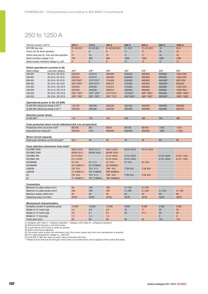
Thermal current Ith (40°C) 250 A 315 A 400 A 630 A 800 A 800 A 1250 ANFC/DIN fuse size B1-B2-B3/1 B1-B2-B3/- B1-B2-B3-B4/2 C1-C2/3 C1-C2-C3/3 -/4 D1/4Frame size for direct operation 5 6 6 17 17 18 18
Switch body size for front and side operation 15 16 16 17 17 18 18Rated insulation voltage Ui (V) 750 800 800 1000 1000 1000 1000Rated impulse withstand voltage Uimp (kV) 8 8 8 12 12 12 12
Rated operational currents Ie (A)Rated voltage Load duty category A/B(1) A/B(1) A/B(1) A/B(1) A/B(1) A/B(1) A/B(1)
400 VAC AC-22 A / AC-22 B 250/250 315/315 400/400 630/630 800/800 800/800 1250/1250400 VAC AC-23 A / AC-23 B 250/250 315/315 400/400 630/630 800/800 800/800 1000/1250690 VAC AC-22 A / AC-22 B 250(2)/250(2) 315(2)/315(2) 315/400 500/630 800/800 800/800(7) 800/1250690 VAC AC-23 A / AC-23 B 250(2)/250(2) 250(2)/315(2) 250/315 315/400 630/630 800/800(7) 800/630220 VDC DC-20 A / DC-20 B 250/250 250/250 315/315 315/630 800/800 800/800 1250/1250220 VDC DC-21 A / DC-21 B 200/200 200/200 200/315 400/630 800/800 800/800 1250/1250440 VDC DC-22 A / DC-22 B 250(3) / 250(3) 250(3) / 250(3) 315(4)/315(4) 315/630(4) 800(3) / 800(3) 800/800 1000(3) / 1000(3)
440 VDC DC-23 A / DC-23 B 200(3) / 200(3) 200(3) / 200(3) 250(4) / 315(4) 400(4)/630(4) 800(3) / 800(3) 800/800(3) 1000(3) / 1000(3)
Operational power in AC-23 (kW) At 400 VAC without pre-break in AC(1)(5) 132/132 160/160 220/220 355/355 450/450 450/450 560/560At 690 VAC without pre-break in AC(1)(5) 220/220 220/295 220/295 295/400 400/400 400/400 400/475
Reactive power (kvar) At 400 VAC(5) 115 145 185 290 365 355 460
Fuse protected short-circuit withstand (kA rms prospective)Prospective short-circuit (kA rms)(6) 80/100 80/- 80/50 80/100 80/100 -/100 -/100Associated fuse rating (A)(6) 250/250 315/- 400/400 630/630 800/800 -/800 -/1250
Short-circuit capacityRated peak withstand current (kA peak)(6) 32.5 40 40 70 80 80 90
Fuse selection (maximum fuse size)(7)
SOCOMEC BS88 6B20 0250 6B30 0315 6B40 0400 6C20 0630 6C30 0800SOCOMEC BS88 6B2M 3015 6B3M 0400 6B4M 0500SOCOMEC DIN 6712 0250 6722 0400 6732 0400 6746 0800 6746 1200SOCOMEC DIN 6713 0250 6723 0400 6733 0400 6747 0800 6747 1200BUSSMANN ED 250 ED 315 ED 400 FF 630 GF 800BUSSMANN DD 200M315 ED 315M400 ED 400M500LAWSON TKF 250 TKF 315 TMF 400 TTM 630 TLM 800LAWSON TF 200M315 TKF 315M400 TMF 400M500GE TKF 250 TKF 315 TMF 400 TTM 630 TLM 800GE TF 200M315 TKF 315M355 TMF 400M450
ConnectionMinimum Cu cable section (mm2) 95 185 185 2 x 150 2 x 185Maximum Cu cable section (mm2) 240 240 240 2 x 300 2 x 300 4 x 185 4 x 185Maximum busbar width (mm) 32 45 45 63 63 80 80Tightening torque min (Nm) 20/26 20/26 20/26 40/45 40/45 40/45 40/45
Mechanical characteristicsDurability (number of operating cycles) 10 000 10 000 10 000 8 000 8 000 5 000 5 000Weight of 3 P switch (kg) 3.2 4.8 4.8 16 17 25 25Weight of 4 P switch (kg) 4.5 6.1 6.1 20 21.5 30 30Weight of 1 P extra (kg) 1.3 1.3 1.3 3 3Frame pitch (mm) 60 66 66 94 94 120 120
250 to 1250 A
(1) Category with index A = frequent operation - Category with index B = infrequent operation.(2) With terminal shrouds or terminal screen.(3) 4-pole device with 2 pole in series by polarity.(4) Poles cannot be juxtaposed.(5) The power value is given for information only, the current values vary from one manufacturer to another.(6) For a rated operational voltage Ue = 400 VAC.(7) Fuse 800 A, 690 Vac does not exist, tests conducted with bars.** Please ensure that fuse let through current does not exceed short-circuit capacity of the switch (kA peak).
FUSERBLOC - Characteristics according to IEC 60947-3 (continued)
163General Catalogue 2011-2012SOCOMEC 163
Fuse combination switchesFUSERBLOC
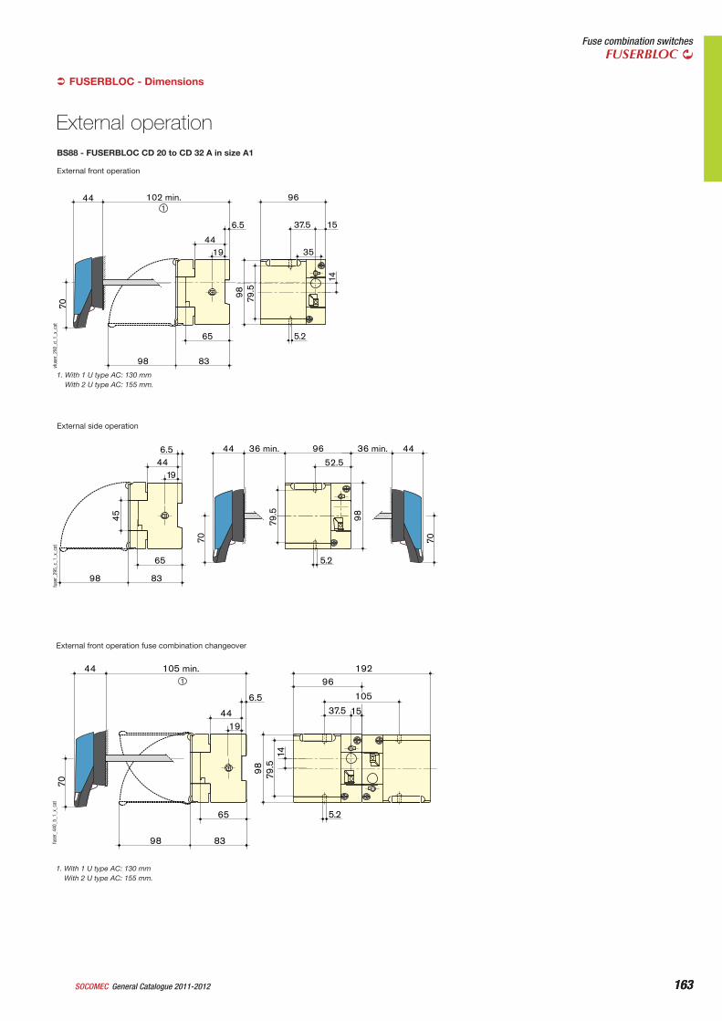
FUSERBLOC - Dimensions‹
External front operation
5.265
8398
14
98 79.5
96
35
102 min.
6.5
1944
37.5 15
144
70vf
user
_292
_d_1
_x_c
at
1. With 1 U type AC: 130 mmWith 2 U type AC: 155 mm.
BS88 - FUSERBLOC CD 20 to CD 32 A in size A1
External side operation
8398
96
5.2
9879.5
36 min.44
52.5
36 min. 446.5
1944
65
45
7070
fuse
r_29
5_c_
1_x_
cat
External front operation fuse combination changeover
5.2
14
98 79.5
192
37.5 15
96
105
65
8398
105 min.44
6.5
1944
1
70fu
ser_
440_
b_1_
x_ca
t
1. With 1 U type AC: 130 mmWith 2 U type AC: 155 mm.
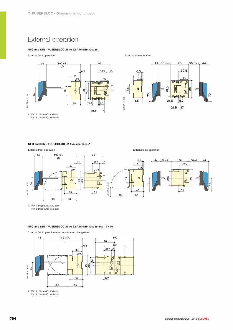
External operation
164 General Catalogue 2011-2012 SOCOMEC164
External side operation
96
1721.5
5.2
35
9879.5
21.5
36 mini44
52.5
36 mini 44
6.5
1944
65
45
7070
fuse
r_29
4_c_
1_x_
cat
External front operation
5.265
8398
14
98 79.5
96
35
102 min.
6.5
1944
37.5 15
144
70
fuse
r_29
2_d_
1_x_
cat
1. With 1 U type AC: 130 mm.With 2 U type AC: 155 mm.
NFC and DIN - FUSERBLOC 32 A in size 14 x 51
96
1721.5
5.2
35
98 79.5
21.5
102 min.
6.5
1944
65
45
14
37.5 15
144
70
fuse
r_29
1_d_
1_x_
cat
1. With 1 U type AC: 130 mm.With 2 U type AC: 155 mm.
NFC and DIN - FUSERBLOC 25 to 32 A in size 10 x 38
External side operation
8398
96
5.29879
.5
36 min.44
52.5
36 min. 446.5
1944
65
45
7070
External front operation
FUSERBLOC - Dimensions (continued)‹
External operation
fuse
r_29
5_c_
1_x_
cat
External front operation fuse combination changeover
5.2
14
98 79.5
192
37.5 15
96
105
65
8398
105 min.44
6.5
1944
1
70
fuse
r_44
0_b_
1_x_
cat
1. With 1 U type AC: 130 mm.With 2 U type AC: 155 mm.
NFC and DIN - FUSERBLOC 25 to 32 A in size 10 x 38 and 14 x 51
165General Catalogue 2011-2012SOCOMEC 165
Fuse combination switchesFUSERBLOC
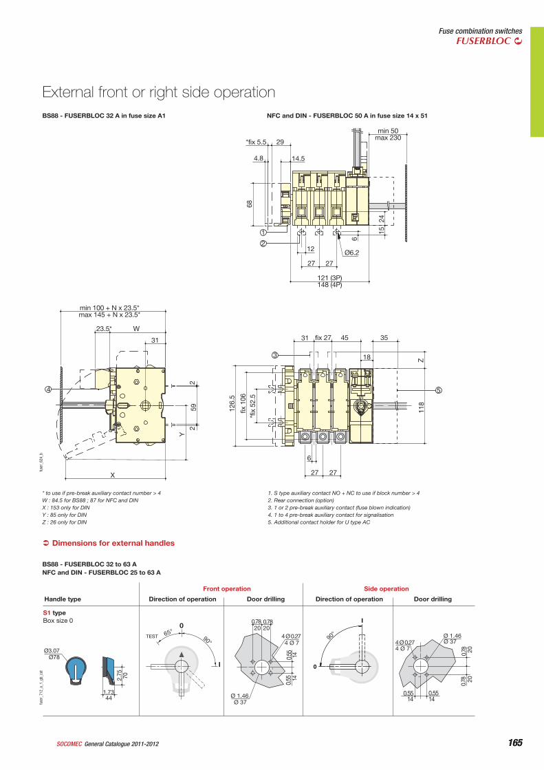
Dimensions for external handles‹
S1 typeBox size 0
0
I
90°
0.78
4 Ø 0.27
0.55
Ø 1.46
Ø3.07
1.73
2.75
65°TEST 90°
I
0
Direction of operationHandle type
Front operation
Door drilling Direction of operation
Side operation
Door drilling
Ø78
70
44Ø 37
1414
4 Ø 7
2020
4 Ø 7Ø 37
2020
140.5514
0.78
Ø 1.46
0.55
0.55
4 Ø 0.27
0.780.78
fuse
r_71
2_a_
1_gb
_cat
BS88 - FUSERBLOC 32 to 63 ANFC and DIN - FUSERBLOC 25 to 63 A
68
6
Z11
8
*fix
52.
5 fix
106
126.
5
2 2
59
Y
24
15
*fix 5.5 29
14.5
min 50 max 230
12
27 27
Ø6.2
31
min 100 + N x 23.5* max 145 + N x 23.5*
23.5* W
31
X
fix 27 45 35
18
6
27 27
4.8
3
54
1
2
121 (3P) 148 (4P)
fuse
r_62
4_b
BS88 - FUSERBLOC 32 A in fuse size A1 NFC and DIN - FUSERBLOC 50 A in fuse size 14 x 51
External front or right side operation
* to use if pre-break auxiliary contact number > 4W : 84.5 for BS88 ; 87 for NFC and DINX : 153 only for DINY : 85 only for DINZ : 26 only for DIN
1. S type auxiliary contact NO + NC to use if block number > 42. Rear connection (option)3. 1 or 2 pre-break auxiliary contact (fuse blown indication)4. 1 to 4 pre-break auxiliary contact for signalisation5. Additional contact holder for U type AC
166 General Catalogue 2011-2012 SOCOMEC166
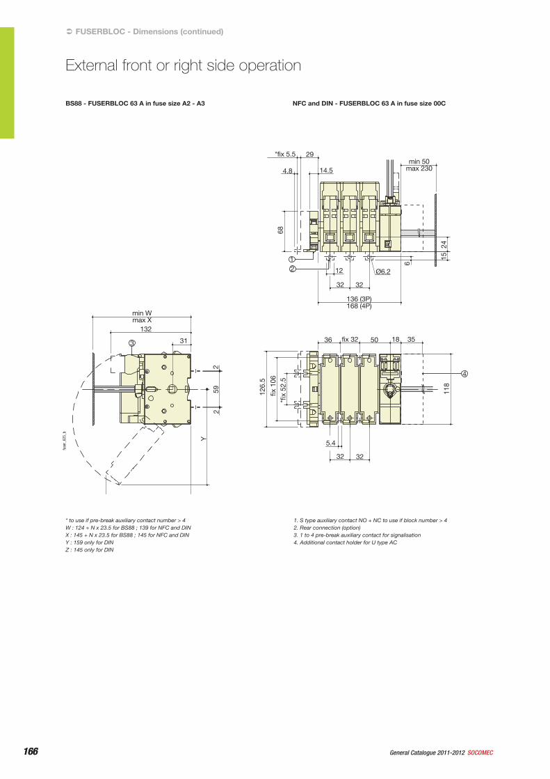
BS88 - FUSERBLOC 63 A in fuse size A2 - A3 NFC and DIN - FUSERBLOC 63 A in fuse size 00C
68
6
15
118
*fix
52.
5 fix
106
126.
5
Y
2 59
2
24
*fix 5.5
4.8 14.5 min 50
max 230
12
32 32
136 (3P) 168 (4P)
36
min Wmax X
132
fix 32 50 18 35
5.4
32 32
Ø6.2
29
3
1 2
31
4
fuse
r_62
5_b
FUSERBLOC - Dimensions (continued)‹
External front or right side operation
* to use if pre-break auxiliary contact number > 4W : 124 + N x 23.5 for BS88 ; 139 for NFC and DINX : 145 + N x 23.5 for BS88 ; 145 for NFC and DINY : 159 only for DINZ : 145 only for DIN
1. S type auxiliary contact NO + NC to use if block number > 42. Rear connection (option)3. 1 to 4 pre-break auxiliary contact for signalisation4. Additional contact holder for U type AC
167General Catalogue 2011-2012SOCOMEC 167
Fuse combination switchesFUSERBLOC
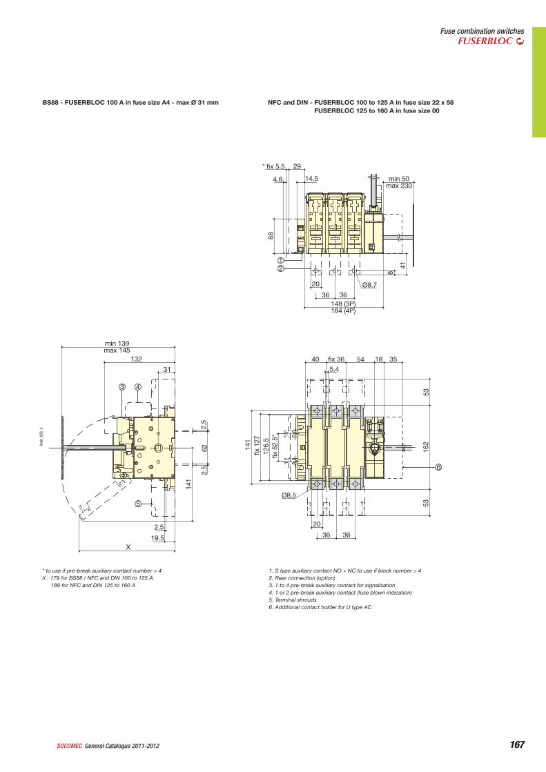
BS88 - FUSERBLOC 100 A in fuse size A4 - max Ø 31 mm NFC and DIN - FUSERBLOC 100 to 125 A in fuse size 22 x 58FUSERBLOC 125 to 160 A in fuse size 00
* fix 5.5
20
36 36Ø8.7
148 (3P)184 (4P)
40 fix 36 545.4
20
36 36
Ø8.5
2.5
19.5X
31
132
min 139max 145
18 35
8
5353
fix 5
2.5*
126.
5fix
127
141
2.5
622.
5
141
162
41
68
4.8 14.5 min 50max 230
29
3 4
12
5
6
fuse
r_62
6_a
* to use if pre-break auxiliary contact number > 4X : 179 for BS88 / NFC and DIN 100 to 125 A
189 for NFC and DIN 125 to 160 A
1. S type auxiliary contact NO + NC to use if block number > 42. Rear connection (option)3. 1 to 4 pre-break auxiliary contact for signalisation4. 1 or 2 pre-break auxiliary contact (fuse blown indication)5. Terminal shrouds6. Additional contact holder for U type AC
168 General Catalogue 2011-2012 SOCOMEC168
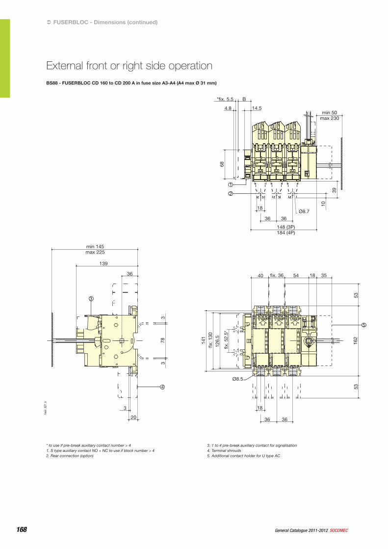
BS88 - FUSERBLOC CD 160 to CD 200 A in fuse size A3-A4 (A4 max Ø 31 mm)
*fix. 5.5 B
4.8 14.5 min 50
max 230
18
40
Ø8.5
min 145 max 225
139
36
3
20
18
36 36
fix. 36 54 18 35
36 36
Ø8.7
148 (3P) 184 (4P)
68
10
53
53
162
141
3 3
78
fix. 1
30
126.
5
fix. 5
2.5*
39
3
1
2
5
4
fuse
r_62
7_b
FUSERBLOC - Dimensions (continued)‹
External front or right side operation
* to use if pre-break auxiliary contact number > 41. S type auxiliary contact NO + NC to use if block number > 42. Rear connection (option)
3. 1 to 4 pre-break auxiliary contact for signalisation4. Terminal shrouds5. Additional contact holder for U type AC
169General Catalogue 2011-2012SOCOMEC 169
Fuse combination switchesFUSERBLOC
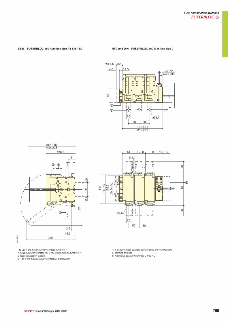
BS88 - FUSERBLOC 160 A in fuse size A4 & B1-B2 NFC and DIN - FUSERBLOC 160 A in fuse size 0
*fix 5.5 29
4.8 14.5 min 50
max 230
20
50
54
min 145 max 225
136.5
31
2.5
19.5
229
5.4
Ø8.5
20
50 50
fix 50 68 18 35
50
Ø8.7
41
8
53
162
fix 5
2.5*
12
6.5
fix 1
40
141
2.5
62
174
2.5
53
68
3 4
1
2
6
5
190 (3P) 240 (4P)
fuse
r_62
8_b
* to use if pre-break auxiliary contact number > 41. S type auxiliary contact NO + NC to use if block number > 42. Rear connection (option)3. 1 to 4 pre-break auxiliary contact for signalisation
4. 1 or 2 pre-break auxiliary contact (fuse blown indication)5. Terminal shrouds6. Additional contact holder for U type AC
170 General Catalogue 2011-2012 SOCOMEC170
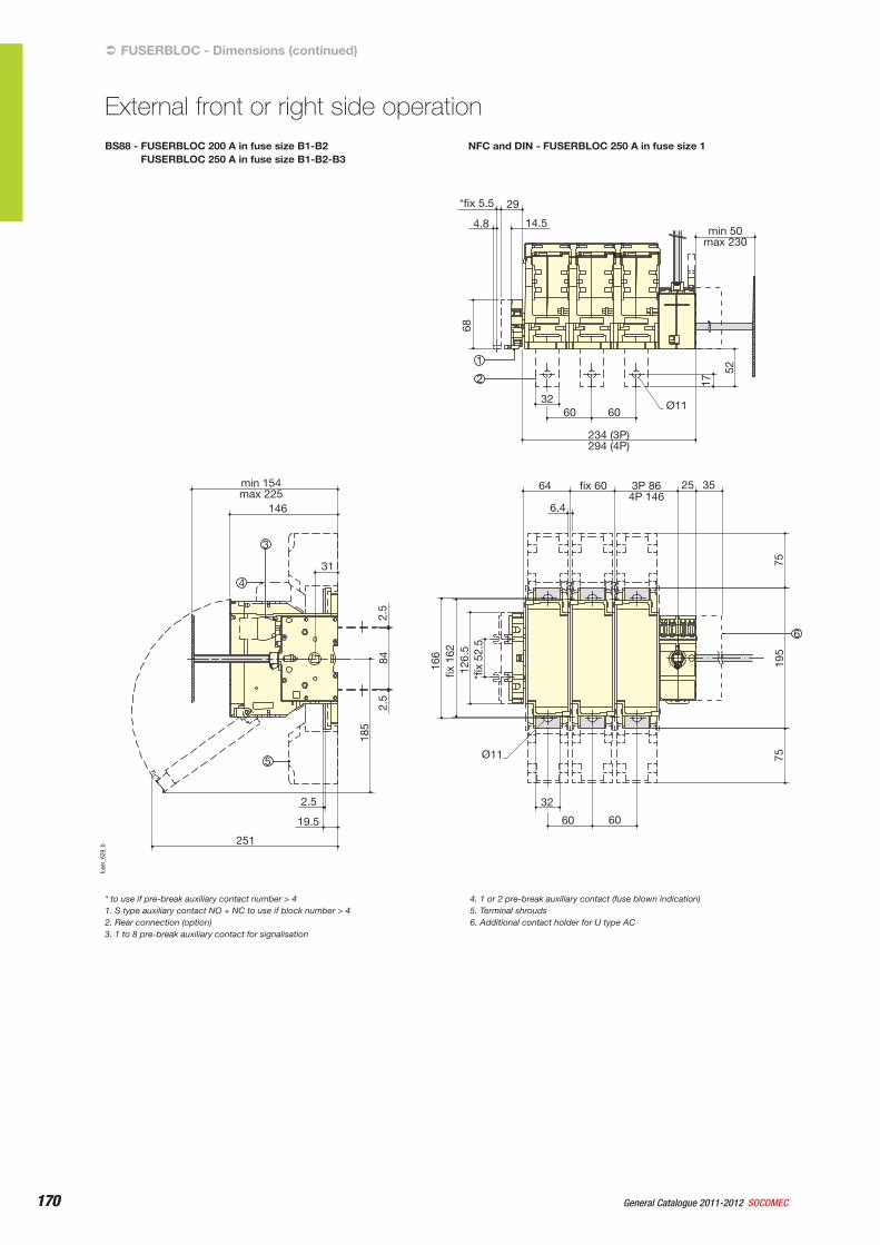
BS88 - FUSERBLOC 200 A in fuse size B1-B2FUSERBLOC 250 A in fuse size B1-B2-B3
NFC and DIN - FUSERBLOC 250 A in fuse size 1
*fix 5.5
32
17 52
75
195
*fix
52.
5 12
6.5
fix 1
62
166
2.5
84
185
2.5
75
68
60
64
6.4
25 35
Ø11
32
60 60
fix 60 3P 86 4P 146
min 154 max 225
146
31
2.5
19.5
251
60 Ø11
29
4.8 14.5 min 50
max 230
4
1
2
5
3
234 (3P) 294 (4P)
6
fuse
r_62
9_b
FUSERBLOC - Dimensions (continued)‹
External front or right side operation
* to use if pre-break auxiliary contact number > 41. S type auxiliary contact NO + NC to use if block number > 42. Rear connection (option)3. 1 to 8 pre-break auxiliary contact for signalisation
4. 1 or 2 pre-break auxiliary contact (fuse blown indication)5. Terminal shrouds6. Additional contact holder for U type AC
171General Catalogue 2011-2012SOCOMEC 171
Fuse combination switchesFUSERBLOC
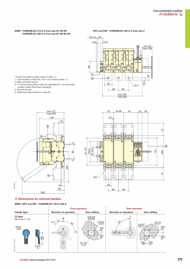
BS88 - FUSERBLOC 315 A in fuse size B1-B2-B3FUSERBLOC 400 A in fuse size B1-B2-B3-B4
NFC and DIN - FUSERBLOC 400 A in fuse size 2
*fix 5.5 29
50
66 66
Ø11
252 (3P) 318 (4P)
70 min 157 max 225
149
31
3
20
260
6.4
Ø11
50
66 66
fix 66 91 25 35
14.5
75
205
175
*fix
52.
5 12
6.5
fix 1
72
3 84
200
3
75
54
68
4.8 14.5
min 50 max 230
4
1
2
6
3
5
fuse
r_63
0_b
* to use if pre-break auxiliary contact number > 41. S type auxiliary contact NO + NC to use if block number > 42. Rear connection (option)3. 1 to 8 pre-break auxiliary contact for signalisation4. 1 or 2 pre-break
auxiliary contact (fuse blown indication)5. Terminal shrouds6. Additional contact holder for U type AC
Dimensions for external handles‹
S2 type Box size 11-16
4 Ø 7
0
I
90°65° 20 20
Ø 37
TEST 90°
I
0
Ø78
1.77
4.92
Direction of operationHandle type
Front operation
Door drilling Direction of operation
Side operation
Door drilling
Ø3.07
0.78 0.78
1414
0.55
0.55
Ø 1.46
4 Ø 0.27
0.78
4 Ø 0.27
0.55
Ø 1.46
4 Ø 7Ø 37
2020
140.5514
0.78
45
125
BS88 / NFC and DIN - FUSERBLOC 100 to 400 A
fuse
r_71
3_a_
1_gb
_cat
172 General Catalogue 2011-2012 SOCOMEC172
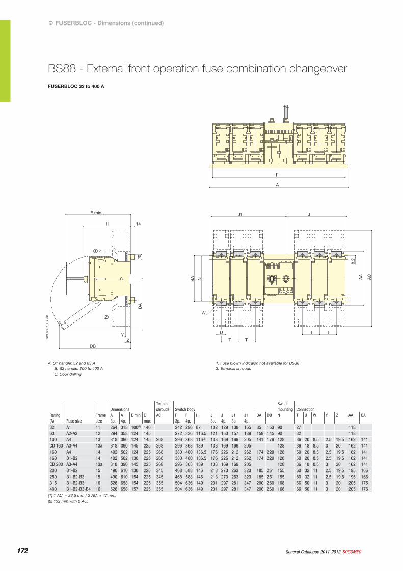
FUSERBLOC 32 to 400 A
F
A
J1
14H
E min. J
TT
T T
U
W
YZ
DB
8.2
NBA
DA
20
AA
AC
1
2
28
404Ø7
ØD
0
90
90
I
Ø78
44
70
Ø78
45
125
A B
C
II
fuse
r_63
4_d_
1_x_
cat
FUSERBLOC - Dimensions (continued)‹
BS88 - External front operation fuse combination changeover
A. S1 handle: 32 and 63 AB. S2 handle: 100 to 400 AC. Door drilling
1. Fuse blown indicaion not available for BS882. Terminal shrouds
Rating (A) Fuse size
Frame size
DimensionsTerminal shrouds Switch body
Switch mounting Connection
A 3p.
A 4p.
E min E max
AC F 3p.
F 4p.
H J 3p.
J 4p.
J1 3p.
J1 4p.
DA DB N T U W Y Z AA BA
32 A1 11 264 318 100(1) 146(1) 242 296 87 102 129 138 165 85 153 90 27 11863 A2-A3 12 294 358 124 145 272 336 116.5 121 153 157 189 159 145 90 32 118100 A4 13 318 390 124 145 268 296 368 116(2) 133 169 169 205 141 179 128 36 20 8.5 2.5 19.5 162 141CD 160 A3-A4 13a 318 390 145 225 268 296 368 139 133 169 169 205 128 36 18 8.5 3 20 162 141160 A4 14 402 502 124 225 268 380 480 136.5 176 226 212 262 174 229 128 50 20 8.5 2.5 19.5 162 141160 B1-B2 14 402 502 130 225 268 380 480 136.5 176 226 212 262 174 229 128 50 20 8.5 2.5 19.5 162 141CD 200 A3-A4 13a 318 390 145 225 268 296 368 139 133 169 169 205 128 36 18 8.5 3 20 162 141200 B1-B2 15 490 610 130 225 345 468 588 146 213 273 263 323 185 251 155 60 32 11 2.5 19.5 195 166250 B1-B2-B3 15 490 610 154 225 345 468 588 146 213 273 263 323 185 251 155 60 32 11 2.5 19.5 195 166315 B1-B2-B3 16 526 658 154 225 355 504 636 149 231 297 281 347 200 260 168 66 50 11 3 20 205 175400 B1-B2-B3-B4 16 526 658 157 225 355 504 636 149 231 297 281 347 200 260 168 66 50 11 3 20 205 175
(1) 1 AC: + 23.5 mm / 2 AC: + 47 mm.(2) 132 mm with 2 AC.
173General Catalogue 2011-2012SOCOMEC 173
Fuse combination switchesFUSERBLOC
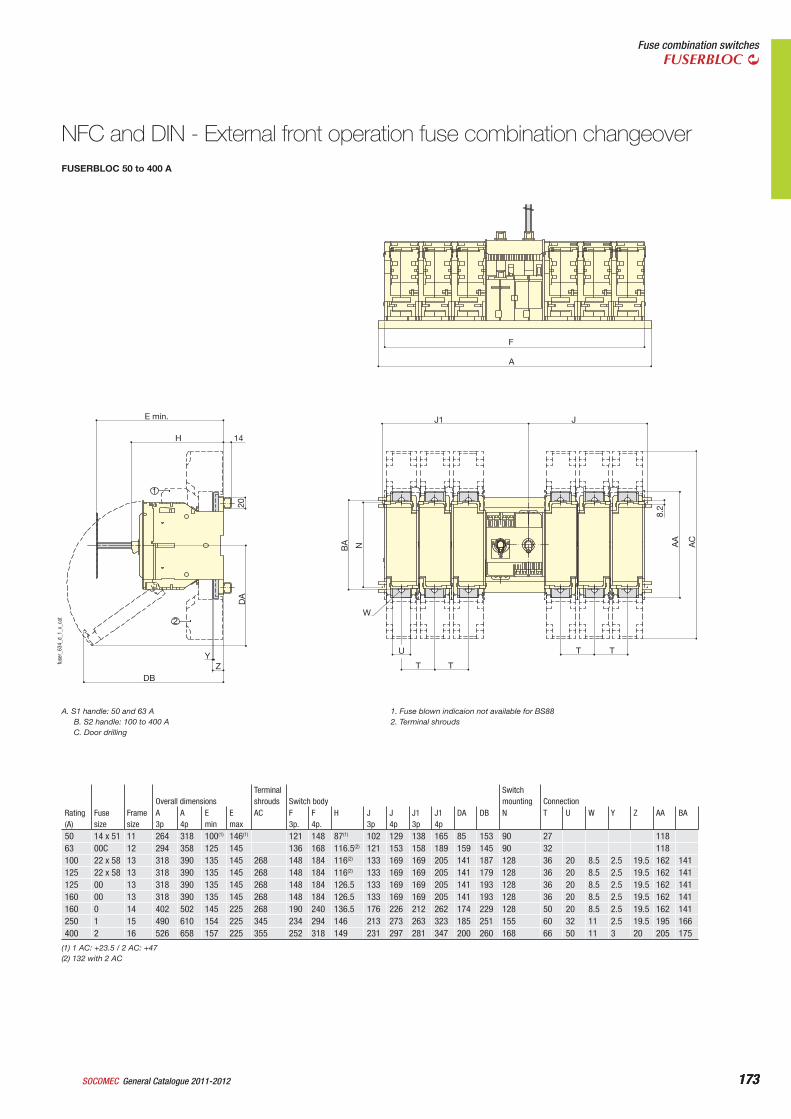
FUSERBLOC 50 to 400 A
F
A
J1
14H
E min. J
TT
T T
U
W
YZ
DB
8.2
NBA
DA
20
AA
AC
1
2
28
404Ø7
ØD
0
90
90
I
Ø78
44
70
Ø78
4512
5
A B
C
II
fuse
r_63
4_d_
1_x_
cat
NFC and DIN - External front operation fuse combination changeover
A. S1 handle: 50 and 63 AB. S2 handle: 100 to 400 AC. Door drilling
1. Fuse blown indicaion not available for BS882. Terminal shrouds
Rating(A)
Fuse size
Frame size
Overall dimensionsTerminal shrouds Switch body
Switch mounting Connection
A 3p
A 4p
E min
E max
AC F 3p.
F 4p.
H J3p
J4p
J13p
J14p
DA DB N T U W Y Z AA BA
50 14 x 51 11 264 318 100(1) 146(1) 121 148 87(1) 102 129 138 165 85 153 90 27 11863 00C 12 294 358 125 145 136 168 116.5(2) 121 153 158 189 159 145 90 32 118100 22 x 58 13 318 390 135 145 268 148 184 116(2) 133 169 169 205 141 187 128 36 20 8.5 2.5 19.5 162 141125 22 x 58 13 318 390 135 145 268 148 184 116(2) 133 169 169 205 141 179 128 36 20 8.5 2.5 19.5 162 141125 00 13 318 390 135 145 268 148 184 126.5 133 169 169 205 141 193 128 36 20 8.5 2.5 19.5 162 141160 00 13 318 390 135 145 268 148 184 126.5 133 169 169 205 141 193 128 36 20 8.5 2.5 19.5 162 141160 0 14 402 502 145 225 268 190 240 136.5 176 226 212 262 174 229 128 50 20 8.5 2.5 19.5 162 141250 1 15 490 610 154 225 345 234 294 146 213 273 263 323 185 251 155 60 32 11 2.5 19.5 195 166400 2 16 526 658 157 225 355 252 318 149 231 297 281 347 200 260 168 66 50 11 3 20 205 175
(1) 1 AC: +23.5 / 2 AC: +47(2) 132 with 2 AC
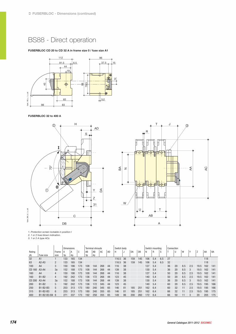
174 General Catalogue 2011-2012 SOCOMEC174
FUSERBLOC CD 20 to CD 32 A in frame size 0 / fuse size A1
FUSERBLOC - Dimensions (continued)‹
BS88 - Direct operation
5.265
8398
14
98 79.5
96
6.591.5
112
19
4437.5 15
45
fuse
r_14
8_c_
1_x_
cat
FUSERBLOC 32 to 400 A
C
31
Z
U T
AB
W
A
Y
H
R
NBA
DA
AA
AC
T JAD
S
DB
70°
2
1
3
fuse
r_06
4_b_
1_x_
cat
1. Protection screen lockable in position I2. 1 or 2 fuse blown indication.3. 1 or 2 A type ACs
Rating (A) Fuse size
Frame size
Dimensions Terminal shrouds Switch body Switch mounting ConnectionA 3p.
A 4p.
C AB 3p
AB 4p
AC AD H J DA DB N R S T U W Y Z AA BA
32 A1 1 133 165 134 116.5 36 159 145 106 5.4 6.5 27 11863 A2-A3 2 133 165 134 116.5 36 159 145 106 5.4 6.5 32 118100 A4 3 150 186 173 108 144 268 44 116 38 127 5.4 36 20 8.5 2.5 19.5 162 141CD 160 A3-A4 3a 152 188 173 108 144 268 44 139 38 130 5.4 36 20 8.5 3 19.5 162 141160 A4 4 150 186 173 108 144 268 44 116 38 127 5.4 50 20 8.5 2.5 19.5 162 141160 B1-B2 4 192 242 173 136 172 268 44 123 45 140 5.4 50 20 8.5 2.5 19.5 162 141CD 200 A3-A4 3a 152 188 173 108 144 268 44 139 38 130 5.4 36 20 8.5 3 19.5 162 141200 B1-B2 5 192 242 173 136 172 345 44 123 45 140 5.4 60 20 8.5 2.5 19.5 195 166250 B1-B2-B3 5 253 313 173 180 240 345 65 146 81 185 251 162 6.4 60 32 11 2.5 19.5 195 166315 B1-B2-B3 6 253 313 173 180 240 355 65 146 81 185 251 162 6.4 66 32 11 2.5 19.5 195 175400 B1-B2-B3-B4 6 271 337 173 192 258 355 65 149 86 200 260 172 6.4 66 50 11 3 20 205 175
175General Catalogue 2011-2012SOCOMEC 175
Fuse combination switchesFUSERBLOC
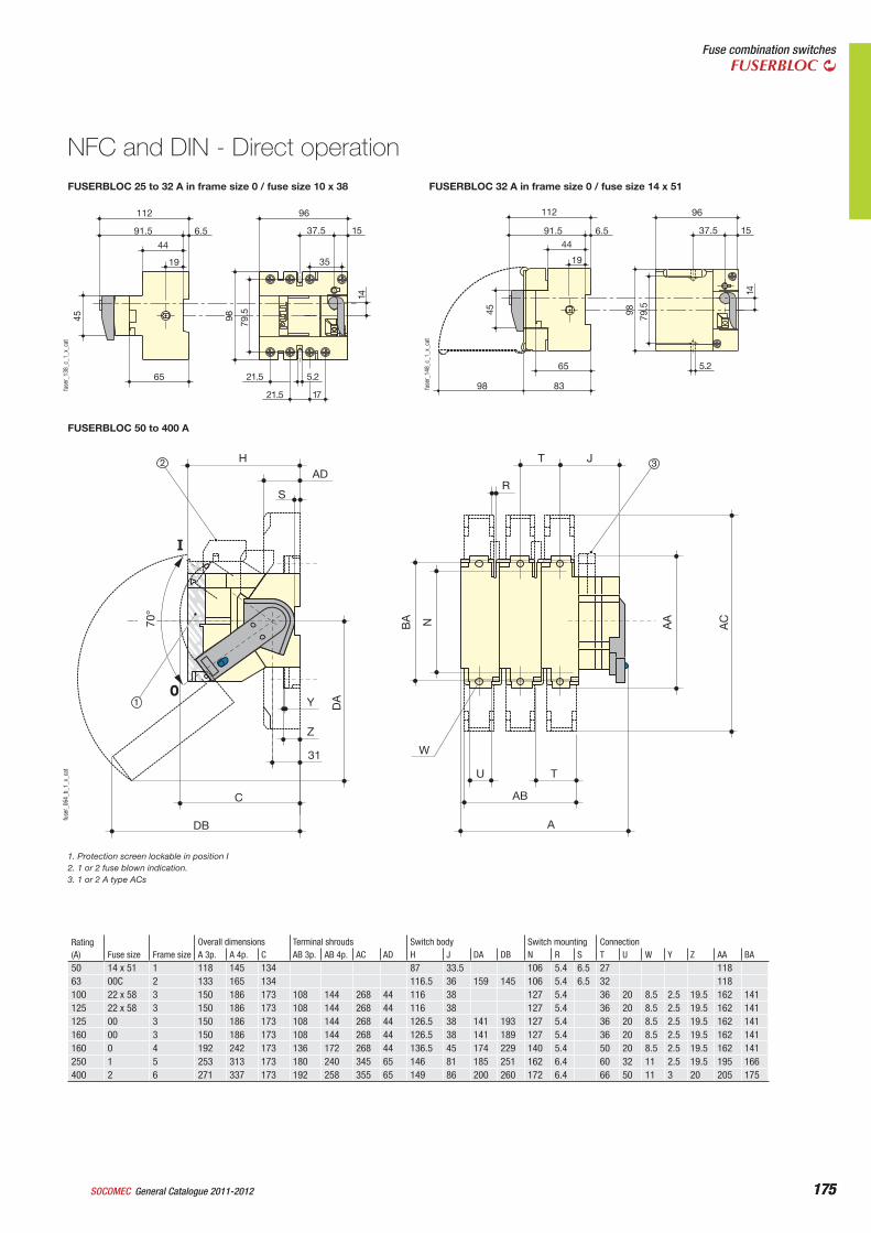
FUSERBLOC 25 to 32 A in frame size 0 / fuse size 10 x 38
NFC and DIN - Direct operation
FUSERBLOC 50 to 400 A
C
31
Z
U T
AB
W
A
Y
H
R
NBA
DA
AA
AC
T JAD
S
DB
70°
2
1
3
fuse
r_06
4_b_
1_x_
cat
1. Protection screen lockable in position I2. 1 or 2 fuse blown indication.3. 1 or 2 A type ACs
96
1721.5
5.2
35
98 79.5
21.5
112
6.591.5
19
44
65
45
14
37.5 15
fuse
r_13
8_c_
1_x_
cat
5.265
8398
14
98 79.5
96
6.591.5
112
19
4437.5 15
45
fuse
r_14
8_c_
1_x_
cat
FUSERBLOC 32 A in frame size 0 / fuse size 14 x 51
Rating (A) Fuse size Frame size
Overall dimensions Terminal shrouds Switch body Switch mounting ConnectionA 3p. A 4p. C AB 3p. AB 4p. AC AD H J DA DB N R S T U W Y Z AA BA
50 14 x 51 1 118 145 134 87 33.5 106 5.4 6.5 27 11863 00C 2 133 165 134 116.5 36 159 145 106 5.4 6.5 32 118100 22 x 58 3 150 186 173 108 144 268 44 116 38 127 5.4 36 20 8.5 2.5 19.5 162 141125 22 x 58 3 150 186 173 108 144 268 44 116 38 127 5.4 36 20 8.5 2.5 19.5 162 141125 00 3 150 186 173 108 144 268 44 126.5 38 141 193 127 5.4 36 20 8.5 2.5 19.5 162 141160 00 3 150 186 173 108 144 268 44 126.5 38 141 189 127 5.4 36 20 8.5 2.5 19.5 162 141160 0 4 192 242 173 136 172 268 44 136.5 45 174 229 140 5.4 50 20 8.5 2.5 19.5 162 141250 1 5 253 313 173 180 240 345 65 146 81 185 251 162 6.4 60 32 11 2.5 19.5 195 166400 2 6 271 337 173 192 258 355 65 149 86 200 260 172 6.4 66 50 11 3 20 205 175
176 General Catalogue 2011-2012 SOCOMEC176
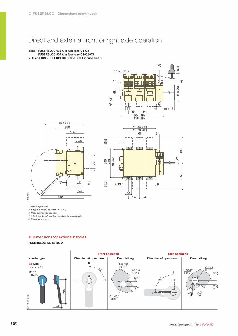
BS88 - FUSERBLOC 630 A in fuse size C1-C2FUSERBLOC 800 A in fuse size C1-C2-C3
NFC and DIN - FUSERBLOC 630 to 800 A in fuse size 3
FUSERBLOC - Dimensions (continued)‹
Direct and external front or right side operation
250
155
79.5
7
59
380
min 265
Ø13
11
Fix 284 (3P) Fix 378 (4P)
65 34
51
9
94 94
11.5
94 94 min 15
364 (3P) 458 (4P)
51
14.5
10.5
fix 2
50
22
235.
5 23
5.5
260
300
85.5
85
.5
7 7
300
90
68
20 46
min
265
85
.5 1
3
2
5
4
fuse
r_63
1_b
1. Direct operation2. S type auxiliary contact NO + NC3. Rear connection (option)4. 1 to 8 pre-break auxiliary contact for signalisation5. Terminal shrouds
Dimensions for external handles‹
S3 typeBox size 17
0
I
90°
61
210
90°
I
0
Direction of operationHandle type
Front operation
Door drilling Direction of operation
Side operation
Door drilling
Ø3.07Ø78
Ø 37
1414
4 Ø 7
2020
Ø 1.46
0.55
0.55
4 Ø 0.27
0.780.78
0.78
4 Ø 0.27
0.55
Ø 1.46
4 Ø 7Ø 37
2020
140.5514
0.78
fuse
r_71
4_a_
1_gb
_cat
FUSERBLOC 630 to 800 A
177General Catalogue 2011-2012SOCOMEC 177
Fuse combination switchesFUSERBLOC
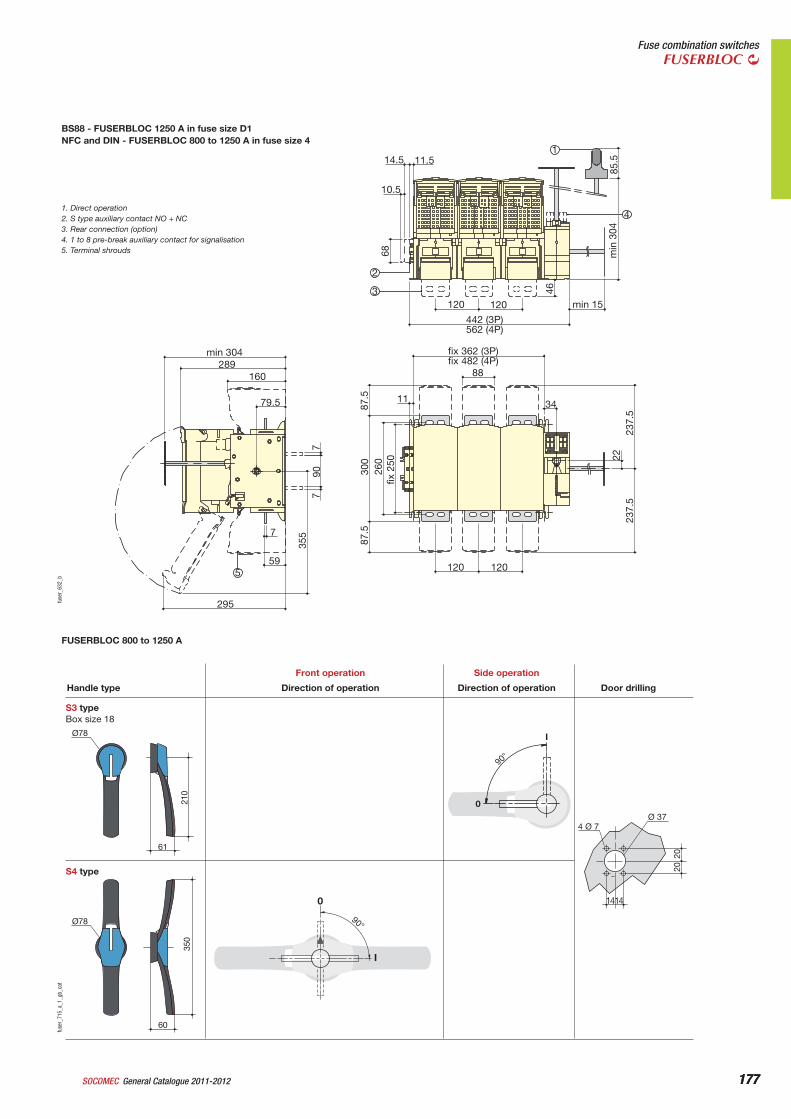
BS88 - FUSERBLOC 1250 A in fuse size D1NFC and DIN - FUSERBLOC 800 to 1250 A in fuse size 4
min 304 289
160
fix 362 (3P) fix 482 (4P)
14.5
10.5
11.5
120 120
442 (3P) 562 (4P)
min 15
88
11 34
120 120
79.5
7
59
295
355
7
87.5
min
304
85
.5
68
46
300
260
fix 2
50 22
237.
5 23
7.5
87.5
90
7
3
4
2
1
5
fuse
r_63
2_b
1. Direct operation2. S type auxiliary contact NO + NC3. Rear connection (option)4. 1 to 8 pre-break auxiliary contact for signalisation5. Terminal shrouds
Ø78
61
210
S3 typeBox size 18
Direction of operationHandle type
Front operation
Direction of operation
Side operation
Door drilling
0
I
90°
2020
4 Ø 7
1414
Ø 37
S4 type
60
350
Ø78 90°
I
0
fuse
r_71
5_a_
1_gb
_cat
FUSERBLOC 800 to 1250 A
Recommended