11th International Conference on DEVELOPMENT AND APPLICATION SYSTEMS, Suceava, Romania, May 17-19, 2012
25
Abstract — Electric railway traction is an important component of the national economy being based on a series of advantages: the cheapest method of traction, free from flux gases, reduced cost maintenance, reduced starting time compared to thermal motor railway traction, high starting torque with excellent dynamics by regenerative braking is possible the energy feedback to the national electric grid.
Index Terms — induction traction motor, motor/generator operation, modeling and simulation, regenerative braking, power converters
I. INTRODUCTION
The AC regenerative braking is possible if the “locomotive” is based on dedicated equipment able to operate the traction motors in generator mode, on one hand, and the traction electrification system – with the most important element, the traction power substations (TPSS) –gives the possibility to recover electrical energy back into the national grid, to be used by other trains in motoring mode of operation. The locomotive equipment is based on the main step-down transformer with more secondary windings the four quadrant line side AC/DC converter, a DC– link circuit and more DC/AC three phase inverters which supply the induction traction motors. In motoring mode of operation, the electrical power is transferred from the national grid, through step-down transformer to the AC/DC converter which is operated as controlled rectifier and the DC/AC converters, typically operated as inverters [1]. By regenerative braking, the induction machine operates as generator, the DC/AC converter – the motor side converter -becomes “rectifier” using the voltage of the DC – link. The AC/DC converter - the line-side converters – becomes inverter and transfers the electrical power to the grid.
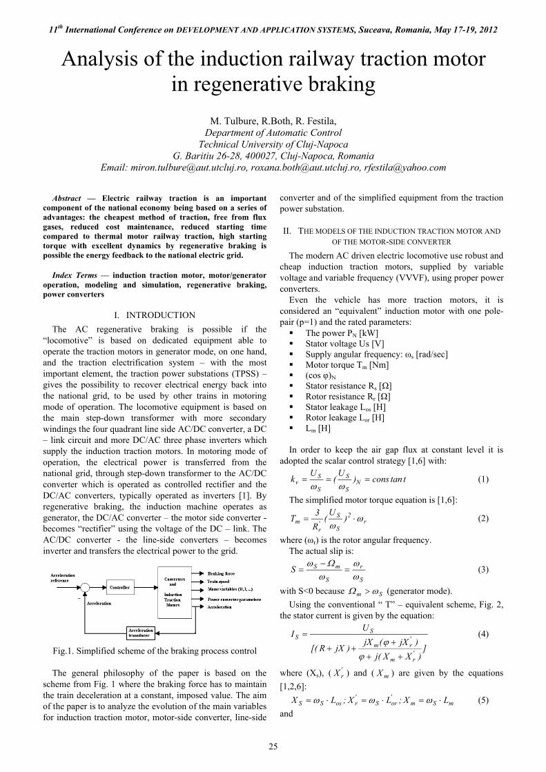
Fig.1. Simplified scheme of the braking process control
The general philosophy of the paper is based on the scheme from Fig. 1 where the braking force has to maintain the train deceleration at a constant, imposed value. The aim of the paper is to analyze the evolution of the main variables for induction traction motor, motor-side converter, line-side
converter and of the simplified equipment from the traction power substation.
II. THE MODELS OF THE INDUCTION TRACTION MOTOR AND
OF THE MOTOR-SIDE CONVERTER
The modern AC driven electric locomotive use robust and cheap induction traction motors, supplied by variable voltage and variable frequency (VVVF), using proper power converters.
Even the vehicle has more traction motors, it is considered an “equivalent” induction motor with one pole-pair (p=1) and the rated parameters: The power PN [kW] Stator voltage Us [V] Supply angular frequency: ωs [rad/sec] Motor torque Tm [Nm] (cos φ)N
Stator resistance Rs [Ω] Rotor resistance Rr [Ω] Stator leakage Los [H] Rotor leakage Lor [H] Lm [H]
In order to keep the air gap flux at constant level it is adopted the scalar control strategy [1,6] with:
ttancons)U
(U
k NS
S
S
Sv
(1)
The simplified motor torque equation is [1,6]:
r2
S
S'r
m )U
(R
3T
(2)
where (ωr) is the rotor angular frequency.The actual slip is:
S
r
S
mSS
(3)
with S<0 because Sm (generator mode).
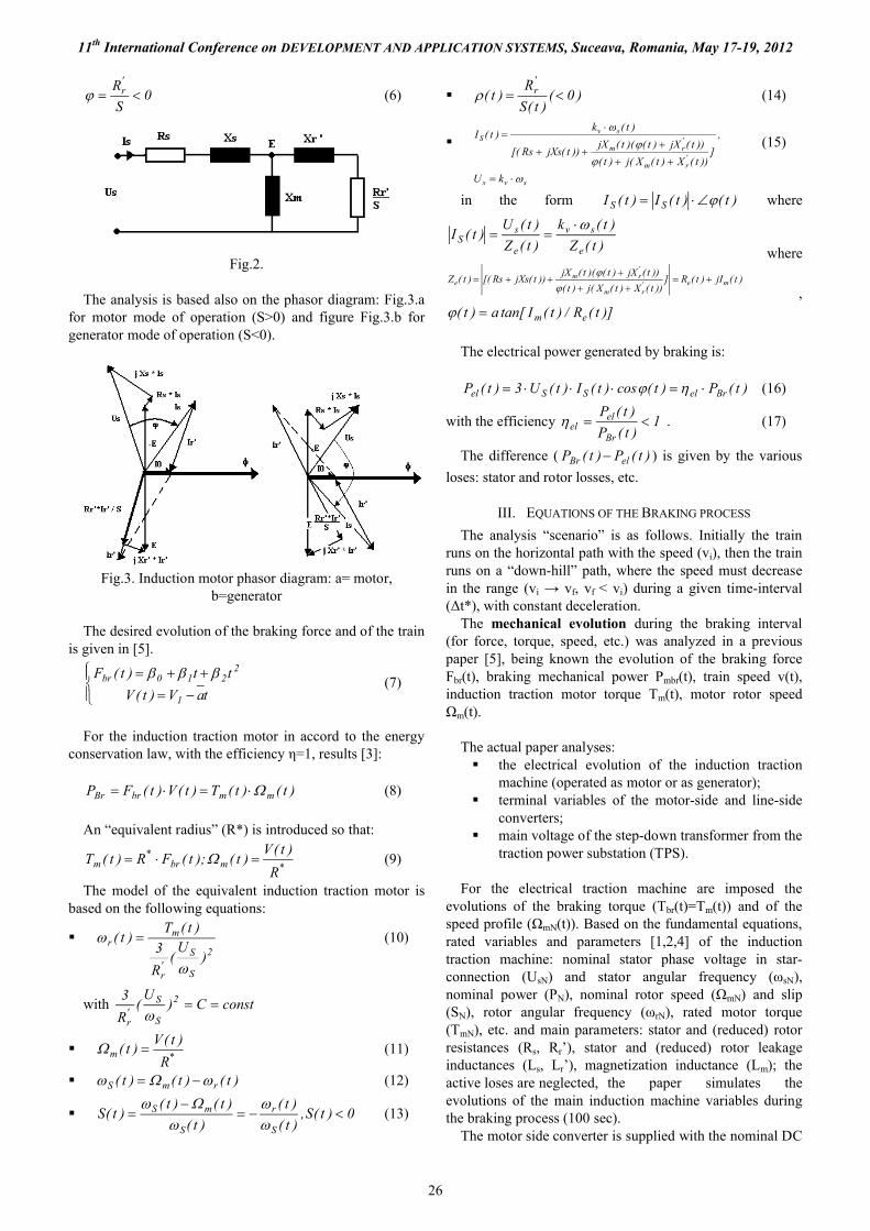
Using the conventional “ T” – equivalent scheme, Fig. 2, the stator current is given by the equation:
])XX(j
)jX(jX)jXR[(
UI
'rm
'rm
SS
(4)
where (Xs), ( 'rX ) and ( mX ) are given by the equations
[1,2,6]:
mSm'orS
'rosSS LX;LX;LX (5)
and
Analysis of the induction railway traction motor in regenerative braking
M. Tulbure, R.Both, R. Festila, Department of Automatic Control
Technical University of Cluj-NapocaG. Baritiu 26-28, 400027, Cluj-Napoca, Romania
Email: [email protected], [email protected], [email protected]
11th International Conference on DEVELOPMENT AND APPLICATION SYSTEMS, Suceava, Romania, May 17-19, 2012
26
0S
R'r (6)
Fig.2.
The analysis is based also on the phasor diagram: Fig.3.a for motor mode of operation (S>0) and figure Fig.3.b for generator mode of operation (S<0).
Fig.3. Induction motor phasor diagram: a= motor,b=generator
The desired evolution of the braking force and of the train is given in [5].
taV)t(V
tt)t(F
1
2210br
(7)
For the induction traction motor in accord to the energy conservation law, with the efficiency η=1, results [3]:
)t()t(T)t(V)t(FP mmbrBr (8)
An “equivalent radius” (R*) is introduced so that:
*mbr*
mR
)t(V)t();t(FR)t(T (9)
The model of the equivalent induction traction motor is based on the following equations:
2
S
S'r
mr
)U
(R
3
)t(T)t(
(10)
with constC)U
(R
3 2
S
S'r
*m
R
)t(V)t( (11)
)t()t()t( rmS (12)
0)t(S,)t(
)t(
)t(
)t()t()t(S
S
r
S
mS
(13)
)0()t(S
R)t(
'r (14)
svs
'rm
'rm
svS
kU
,
]))t(X)t(X(j)t(
))t(jX)t()(t(jX))t(jXsRs[(
)t(k)t(I
(15)
in the form )t()t(I)t(I SS where
)t(Z
)t(k
)t(Z
)t(U)t(I
e
sv
e
sS
where
)t(jI)t(R]))t(X)t(X(j)t(
))t(jX)t()(t(jX))t(jXsRs[()t(Z me'
rm
'rm
e
,)]t(R/)t(Itan[a)t( em
The electrical power generated by braking is:
)t(P)t(cos)t(I)t(U3)t(P BrelSSel (16)
with the efficiency 1)t(P
)t(P
Br
elel . (17)
The difference ( )t(P)t(P elBr ) is given by the various
loses: stator and rotor losses, etc.
III. EQUATIONS OF THE BRAKING PROCESS
The analysis “scenario” is as follows. Initially the train runs on the horizontal path with the speed (vi), then the train runs on a “down-hill” path, where the speed must decrease in the range (vi → vf, vf < vi) during a given time-interval (Δt*), with constant deceleration.
The mechanical evolution during the braking interval (for force, torque, speed, etc.) was analyzed in a previous paper [5], being known the evolution of the braking force Fbr(t), braking mechanical power Pmbr(t), train speed v(t), induction traction motor torque Tm(t), motor rotor speed Ωm(t).
The actual paper analyses: the electrical evolution of the induction traction
machine (operated as motor or as generator); terminal variables of the motor-side and line-side
converters; main voltage of the step-down transformer from the
traction power substation (TPS).
For the electrical traction machine are imposed the evolutions of the braking torque (Tbr(t)=Tm(t)) and of the speed profile (ΩmN(t)). Based on the fundamental equations, rated variables and parameters [1,2,4] of the induction traction machine: nominal stator phase voltage in star-connection (UsN) and stator angular frequency (ωsN), nominal power (PN), nominal rotor speed (ΩmN) and slip (SN), rotor angular frequency (ωrN), rated motor torque (TmN), etc. and main parameters: stator and (reduced) rotor resistances (Rs, Rr’), stator and (reduced) rotor leakage inductances (Ls, Lr’), magnetization inductance (Lm); the active loses are neglected, the paper simulates the evolutions of the main induction machine variables during the braking process (100 sec).
The motor side converter is supplied with the nominal DC
11th International Conference on DEVELOPMENT AND APPLICATION SYSTEMS, Suceava, Romania, May 17-19, 2012
27
voltage (UDCN) in order to generate the stator voltage (UsN). The ratio (UDCN / UsN) will be kept constant [3], in this way being possible to determine the value of the DC-link voltage.
The input voltage (U1) of the line side converter, given by the secondary winding of the step-down transformer from the traction power substation is estimated from the equation: U1≈UDC / (1,41*η), [3].
IV. BRAKING PROCESS SIMULATION
The numerical data selected for simulation are:a. For the equivalent (hypothetic) induction traction
motor:PN=250kW;nN=2900 rot/min; ΩmN=303.53 rad/sec;UsN=750 V;fsN=50Hz; ωsN=314 rad/sec;ku= UsN/ ωsN=750/314=2.388;cos φN=0.85;Rs=0.289 Ω;Rr’=0.217 Ω;Ls=1.90*10-3
;
Lr’=2.39*10-3;
Ls=5.59*10-2;
b. Mechanical data for the braking process:Fbr(t)=11375.25+9t-0.0225t2 [N] for t=(0-100sec)v(t)=25-0.15t [m/s]Pbr(t)=Pmec(t)=(Fbr(t)*v(t)) [W]Equivalent radius R*=0.0747 [p.u]Tm(t)= η * R* * Fbr(t)=0.89*0.0747* Fbr(t)Ωm(t)=v(t)/ R*
ωr(t)=Tm(t)/C; C=78.87 [p.u]ωs(t)= Ωm(t)- ωr(t)Us(t)= (UsN/IsN)* ωs(t)= 2.388* ωs(t)Regenerated power for the national grid Pg
Pg(t)=ηg*3Us(t)*Is(t)*cosφs(t); ηg≈0.75S(t)= ωr(t)/ ωs(t) (<0)Xs(t)= ωs(t)*Ls=1.9*10-3* ωs(t)Xr’(t) = ωs(t)*Lr’=2.39*10-3* ωs(t)Xm(t)= ωs(t)*Lm=5.59*10-2* ωs(t)ρ(t)=-Rr’/S(t)=-0.217/S(t)
c. For the DC link circuit of the motor-side converterUDC(t)=(UDCN/UsN)*Us(t)=(1100/750)**Us(t)=1.466*Us(t)
d. For the line-side converter, secondary voltage of the step down transformer from TPS: U1(t)=(1/1.41*η)*UDC(t)
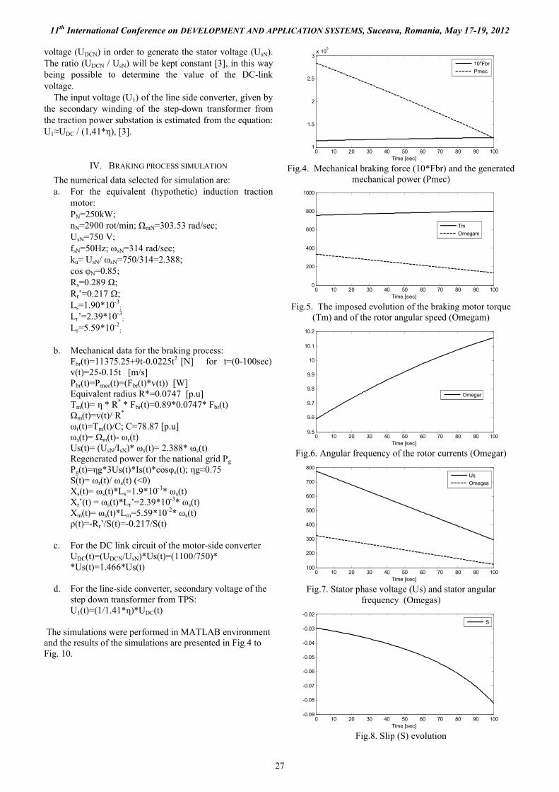
The simulations were performed in MATLAB environment and the results of the simulations are presented in Fig 4 to Fig. 10.
0 10 20 30 40 50 60 70 80 90 1001
1.5
2
2.5
3x 10
5
Time [sec]
10*Fbr
Pmec
Fig.4. Mechanical braking force (10*Fbr) and the generated mechanical power (Pmec)
0 10 20 30 40 50 60 70 80 90 1000
200
400
600
800
1000
Time [sec]
Tm
Omegam
Fig.5. The imposed evolution of the braking motor torque (Tm) and of the rotor angular speed (Omegam)
0 10 20 30 40 50 60 70 80 90 1009.5
9.6
9.7
9.8
9.9
10
10.1
10.2
Time [sec]
Omegar
Fig.6. Angular frequency of the rotor currents (Omegar)
0 10 20 30 40 50 60 70 80 90 100100
200
300
400
500
600
700
800
Time [sec]
Us
Omegas
Fig.7. Stator phase voltage (Us) and stator angular frequency (Omegas)
0 10 20 30 40 50 60 70 80 90 100-0.09
-0.08
-0.07
-0.06
-0.05
-0.04
-0.03
-0.02
Time [sec]
S
Fig.8. Slip (S) evolution
11th International Conference on DEVELOPMENT AND APPLICATION SYSTEMS, Suceava, Romania, May 17-19, 2012
28
0 10 20 30 40 50 60 70 80 90 100115
120
125
130
135
140
145
150
Time [sec]
IIs
-fIIS
Fig.9. Statoric phase current (IIs, A) and voltage – current phase displacement (-fIIs, deg)
0 10 20 30 40 50 60 70 80 90 1000.8
1
1.2
1.4
1.6
1.8
2
2.2
2.4x 10
5
Time [sec]
PIIs
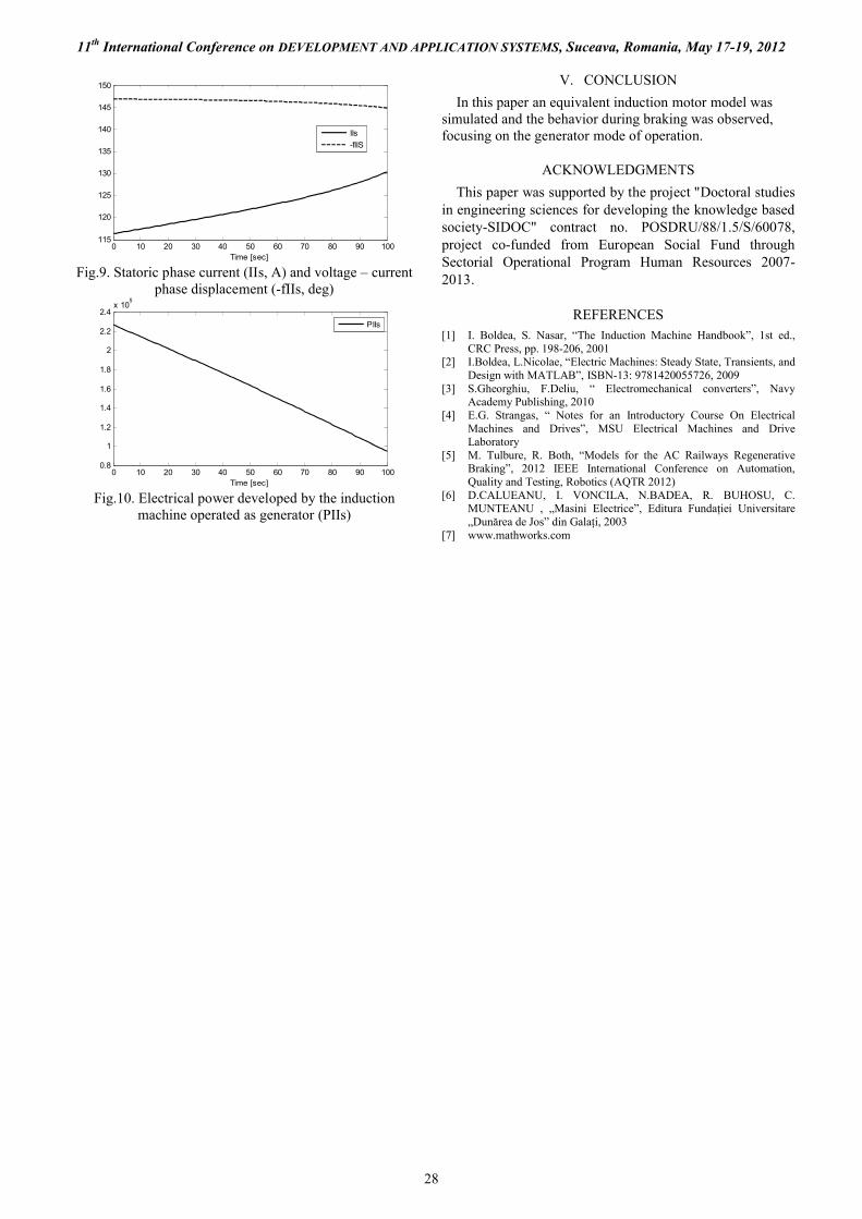
Fig.10. Electrical power developed by the induction machine operated as generator (PIIs)
V. CONCLUSION
In this paper an equivalent induction motor model was simulated and the behavior during braking was observed, focusing on the generator mode of operation.
ACKNOWLEDGMENTS
This paper was supported by the project "Doctoral studies in engineering sciences for developing the knowledge based society-SIDOC" contract no. POSDRU/88/1.5/S/60078, project co-funded from European Social Fund through Sectorial Operational Program Human Resources 2007-2013.
REFERENCES[1] I. Boldea, S. Nasar, “The Induction Machine Handbook”, 1st ed.,
CRC Press, pp. 198-206, 2001[2] I.Boldea, L.Nicolae, “Electric Machines: Steady State, Transients, and
Design with MATLAB”, ISBN-13: 9781420055726, 2009[3] S.Gheorghiu, F.Deliu, “ Electromechanical converters”, Navy
Academy Publishing, 2010[4] E.G. Strangas, “ Notes for an Introductory Course On Electrical
Machines and Drives”, MSU Electrical Machines and Drive Laboratory
[5] M. Tulbure, R. Both, “Models for the AC Railways Regenerative Braking”, 2012 IEEE International Conference on Automation, Quality and Testing, Robotics (AQTR 2012)
[6] D.CALUEANU, I. VONCILA, N.BADEA, R. BUHOSU, C. MUNTEANU , „Masini Electrice”, Editura Fundaţiei Universitare „Dunărea de Jos” din Galaţi, 2003
[7] www.mathworks.com
Recommended


![REGENERATIVE BRAKING SYSTEM IN ELECTRIC VEHICLES · REGENERATIVE BRAKING SYSTEM IN ELECTRIC VEHICLES ... REGENERATIVE BRAKING SYSTEM ... Regenerative action during braking[9]](https://img.pdfslide.us/doc/110x75/5adccef67f8b9a1a088c7cf0/regenerative-braking-system-in-electric-vehicles-braking-system-in-electric-vehicles.jpg)