1
Lecture 18:Introduction to Multiprocessors
Prepared and presented by:
Kurt Keutzer
with thanks for materials from
Kunle Olukotun, Stanford;
David Patterson, UC Berkeley
2
Why Multiprocessors?
Needs Relentless demand for higher performance
» Servers» Networks
Commercial desire for product differentiation
Opportunities Silicon capability Ubiquitous computers

3
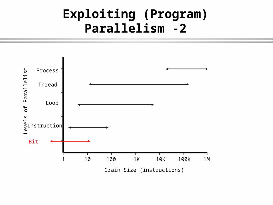
Exploiting (Program) Parallelism
Instruction
Loop
Thread
Process
Leve
ls o
f P
aral
lelis
m
Grain Size (instructions)
1 10 100 1K 10K 100K 1M
4
Exploiting (Program) Parallelism -2
Instruction
Loop
Thread
Process
Leve
ls o
f P
aral
lelis
m
Grain Size (instructions)
1 10 100 1K 10K 100K 1M
Bit

5
Need for Parallel Computing
Diminishing returns from ILP» Limited ILP in programs» ILP increasingly expensive
to exploit
Peak performance increases linearly with more processors» Amhdahl’s law applies
Adding processors is inexpensive» But most people add
memory also
Die Area
Per
form
ance
Die Area
Per
form
ance
P+M
2P+M 2P+2M

6
What to do with a billion transistors ?
Technology changes the cost and performance of computer elements in a non-uniform manner
» logic and arithmetic is becoming plentiful and cheap
» wires are becoming slow and scarce
This changes the tradeoffs between alternative architectures
» superscalar doesn’t scale well
– global control and data So what will the architectures
of the future be?
2007
2004
2001
1998
1 clk
3 (10, 16, 20?) clks
64 x the area4x the speedslower wires

7
Elements of a multiprocessing system
General purpose/special purpose Granularity - capability of a basic module Topology - interconnection/communication geometry Nature of coupling - loose to tight Control-data mechanisms Task allocation and routing methodology Reconfigurable
» Computation» Interconnect
Programmer’s model/Language support/ models of computation
Implementation - IC, Board, Multiboard, Networked Performance measures and objectives
[After E. V. Krishnamurty - Chapter 5

8
Use, Granularity
General purpose attempting to improve general purpose computation (e.g. Spec
benchmarks) by means of multiprocessing
Special purpose attempting to improve a specific application or class of
applications by means of multiprocessing
Granularity - scope and capability of a processing element (PE) Nand gate ALU with registers Execution unit with local memory RISC R1000 processor

9
Topology
Topology - method of interconnection of processors Bus Full-crossbar switch Mesh N-cube Torus Perfect shuffle, m-shuffle Cube-connected components Fat-trees

10
Coupling
Relationship of communication among processors Shared clock (Pipelined) Shared registers (VLIW) Shared memory (SMM) Shared network

11
Control/Data
Way in which data and control are organized
Control - how the instruction stream is managed (e.g. sequential instruction fetch)
Data - how the data is accessed (e.g. numbered memory addresses)
Multithreaded control flow - explicit constructs: fork, join, wait, control program flow - central controller
Dataflow model - instructions execute as soon as operands are ready, program structures flow of data, decentralized control

12
Task allocation and routing
Way in which tasks are scheduled and managed
Static - allocation of tasks onto processing elements pre-determined before runtime
Dynamic - hardware/software support allocation of tasks to processors at runtime

13
Reconfiguration
Computational restructuring of computational elements
» reconfigurable - reconfiguration at compile time» dynamically reconfigurable- restructuring of computational
elements at runtime
Interconnection scheme switching network - software controlled reconfigurable fabric

14
Programmer’s model
How is parallelism expressed by the user?
Expressive power Process-level parallelism
» Shared-memory» Message-passing
Operator-level parallelism Bit-level parallelism
Formal guarantees Deadlock-free Livelock free
Support for other real-time notions Exception handling

15
Parallel Programming Models
Message Passing» Fork thread
– Typically one per node» Explicit communication
– Send messages– send(tid, tag, message)– receive(tid, tag, message)
» Synchronization– Block on messages
(implicit sync)– Barriers
Shared Memory (address space)» Fork thread
– Typically one per node» Implicit communication
– Using shared address space
– Loads and stores» Synchronization
– Atomic memory operators– barriers
16
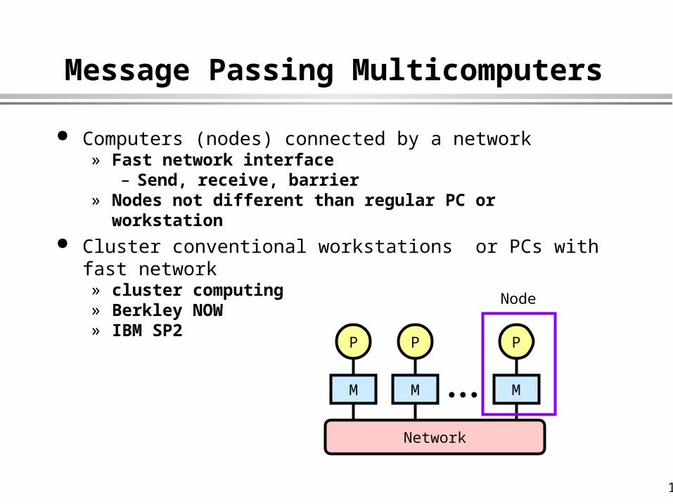
Message Passing Multicomputers
Computers (nodes) connected by a network» Fast network interface
– Send, receive, barrier» Nodes not different than regular PC or workstation
Cluster conventional workstations or PCs with fast network » cluster computing» Berkley NOW» IBM SP2
P
M
P
M
P
M
Network
Node

17
Shared-Memory Multiprocessors
Several processors share one address space
» conceptually a shared memory
» often implemented just like a multicomputer
– address space distributed over private memories
Communication is implicit» read and write accesses to
shared memory locations Synchronization
» via shared memory locations– spin waiting for non-zero
» barriers
P
M
Network
P P
Conceptual Model
P
M
P
M
P
M
Network
Actual Implementation

18
Cache Coherence - A Quick Overview
With caches, action is required to prevent access to stale data
» Processor 1 may read old data from its cache instead of new data in memory or
» Processor 3 may read old data from memory rather than new data in Processor 2’s cache
Solutions» no caching of shared data
– Cray T3D, T3E, IBM RP3, BBN Butterfly
» cache coherence protocol– keep track of copies– notify (update or
invalidate) on writes
P1
M
Network
P2 PN
$ $ $
P1: Rd(A) Rd(A)
P2: Wr(A,5)
P3: Rd(A)
A:3

19
Implementation issues
Underlying hardware implementation Bit-slice Board assembly Integration in an integrated-circuit
Exploitation of new technologies DRAM integration on IC Low-swing chip-level interconnect

20
Performance objectives
Objectives Speed Power Cost Ease of programming/time to market/ time to money In-field flexibility
Methods of measurement Modeling Emulation Simulation
» Transaction» Instruction-set» Hardware

21
Flynn’s Taxonomy of Multiprocessing
Single-instruction single-datastream (SISD) machines
Single-instruction multiple-datastream (SIMD) machines
Multiple-instruction single-datastream (MISD) machines
Multiple-instruction multiple-datastream (MIMD) machines
Examples?

22
Examples
Single-instruction single-datastream (SISD) machines» Non-pipelined Uniprocessors
Single-instruction multiple-datastream (SIMD) machines» Vector processors (VIRAM)
Multiple-instruction single-datastream (MISD) machines» Network processors (Intel IXP1200
Multiple-instruction multiple-datastream (MIMD) machines» Network of workstations (NOW)

23
Predominant Approaches
Pipelining ubiquitious
Much academic research focused on performance improvements of ``dusty decks’’
Illiac 4 - Speed-up of Fortran SUIF, Flash - Speed-up of C
Niche market in high-performance computing Cray
Commercial support for high-end servers Shared-memory multiprocessors for server market
Commercial exploitation of silicon capability General purpose: Super-scalar, VLIW Special purpose: VLIW for DSP, Media processors, Network
processors
Reconfigurable computing

24
Fetch
PG PS PW PR DP DC E1 E2 E3 E4 E5
Decode Execute
Execute Packet 1
C62x Pipeline OperationPipeline Phases
Single-Cycle Throughput Operate in Lock Step Fetch
» PG Program Address Generate» PS Program Address Send» PW Program Access Ready Wait» PR Program Fetch Packet Receive
Decode» DP Instruction Dispatch» DC Instruction Decode
Execute» E1 - E5 Execute 1 through Execute 5
PG PS PW PR DP DC E1 E2 E3 E4 E5Execute Packet 2 PG PS PW PR DP DC E1 E2 E3 E4 E5
Execute Packet 3 PG PS PW PR DP DC E1 E2 E3 E4 E5Execute Packet 4 PG PS PW PR DP DC E1 E2 E3 E4 E5
Execute Packet 5 PG PS PW PR DP DC E1 E2 E3 E4 E5Execute Packet 6 PG PS PW PR DP DC E1 E2 E3 E4 E5
Execute Packet 7 PG PS PW PR DP DC E1 E2 E3 E4 E5

25
Superscalar: PowerPC 604 and Pentium Pro
Both In-order Issue, Out-of-order execution, In-order Commit

26
IA-64 aka EPIC aka VLIW
Compiler schedules instructions Encodes dependencies
explicitly» saves having the hardware
repeatedly rediscover them Support speculation
» speculative load» branch prediction
Really need to make communication explicit too
» still has global registers and global instruction issue
Register File
Instruction Cache
Instruction Issue

27
Phillips Trimedia Processor

28
TMS320C6201 Revision 2
C6201 CPU Megamodule
Data Path 1
D1M1S1L1
A Register File
Data Path 2
L2S2M2D2
B Register File
Instruction Dispatch
Program Fetch
Interrupts
Control Registers
Control Logic
Emulation
Test
Ext. Memory Interface
4-DMA
Program Cache / Program Memory32-bit address, 256-Bit data512K Bits RAM
Host Port
Interface
2 Timers
2 Multi-channel buffered
serial ports (T1/E1)
Data Memory32-Bit address, 8-, 16-, 32-Bit data
512K Bits RAM
Pwr Dwn
Instruction Decode

29
TMS320C6701 DSP Block Diagram
’C67x Floating-Point CPU Core
Data Path 1
D1M1S1L1
A Register File
Data Path 2
L2S2M2D2
B Register File
Instruction Dispatch
Program Fetch
Interrupts
Control Registers
Control Logic
Emulation
Test
External Memory Interface
4 Channel
DMA
Program Cache/Program Memory32-bit address, 256-Bit data
512K Bits RAM
Host Port
Interface
2 Timers
2 Multi-channel buffered
serial ports (T1/E1)
Data Memory32-Bit address
8-, 16-, 32-Bit data512K Bits RAM
Power Down
Instruction Decode

30
ArithmeticLogicUnit
AuxiliaryLogicUnit
MultiplierUnit
’C67x Floating-Point CPU Core
Data Path 1
D1M1S1L1
A Register File
Data Path 2
L2S2M2D2
B Register File
Instruction Decode
Instruction Dispatch
Program Fetch
Interrupts
Control Registers
Control Logic
Emulation
Test
Floating-PointCapabilities
TMS320C67x CPU Core
31
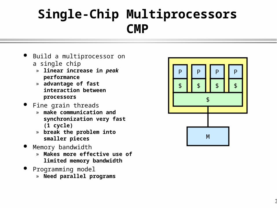
Single-Chip MultiprocessorsCMP
Build a multiprocessor on a single chip
» linear increase in peak performance
» advantage of fast interaction between processors
Fine grain threads» make communication and
synchronization very fast (1 cycle)
» break the problem into smaller pieces
Memory bandwidth» Makes more effective use of
limited memory bandwidth Programming model
» Need parallel programs
P P P P
$ $ $ $
$
M

32
Intel IXP1200 Network Processor
6 micro-engines» RISC engines» 4 contexts/eng» 24 threads total
IX Bus Interface» packet I/O» connect IXPs
– scalable StrongARM
» less critical tasks Hash engine
» level 2 lookups PCI interface
SDRAMCtrl
MicroEng
PCIInterface
SRAMCtrl
SACore
MicroEng
MicroEng
MicroEng
MicroEng
MicroEng
MiniDCache
DCache
ICache
ScratchPad
SRAM
IX BusInterface
HashEngine

33
IXP1200 MicroEngine
32-bit RISC instruction set Multithreading support for 4 threads
» Maximum switching overhead of 1 cycle 128 32-bit GPRs in two banks of 64 Programmable 1KB instruction store (not shown in diagram) 128 32-bit transfer registers Command bus arbiter and FIFO (not shown in diagram)
32 SRAMRead XFERRegisters
64 GPRs(A-Bank)
32 SDRAMRead XFER
Registers
64 GPRs(B-Bank)
ALU
32 SRAMWrite XFER
Registers
32 SDRAMRead XFER
Registers
from SRAM
from SDRAM
to SRAM
to SDRAM

34
IXP1200 Instruction Set
Powerful ALU instructions:» can manipulate word and part of word quite effectively
Swap-thread on memory reference» Hides memory latency» sram[read, r0, base1, offset, 1], ctx_swap
Can use an “intelligent” DMA-like controller to copy packets to/from memory» sdram[t_fifo_wr, --, pkt_bffr, offset, 8]
Exposed branch behavior» can fill variable branch slots» can select a static prediction on a per-branch basis
ARMmov r1, r0, lsl #16mov r1, r1, r0, asr #16add r0, r1, r0, asr #16
IXP1200ld_field_w_clr[temp, 1100, accum]alu_shf[accum, temp, +, accum, <<16]

35
UCB: Processor with DRAM (PIM)IRAM, VIRAM
Put the processor and the main memory on a single chip
» much lower memory latency» much higher memory
bandwidth
But» need to build systems with
more than one chip
M
P
64Mb SDRAM ChipInternal - 128 512K subarrays4 bits per subarray each 10ns51.2 Gb/s
External - 8 bits at 10ns, 800Mb/s
1 Integer processor ~ 100KBytes DRAM1 FP processor ~ 500KBytes DRAM
1 Vector Unit ~ 1 MByte DRAM
V

36
IRAM Vision Statement
Microprocessor & DRAM on a single chip:» on-chip memory latency
5-10X, bandwidth 50-100X» improve energy efficiency
2X-4X (no off-chip bus)» serial I/O 5-10X v. buses» smaller board area/volume» adjustable memory size/width
DRAM
fab
Proc
Bus
D R A M
$ $Proc
L2$
Logic
fabBus
D R A M
I/OI/O
I/OI/O
Bus

37
Potential Multimedia Architecture
“New” model: VSIW=Very Short Instruction Word!» Compact: Describe N operations with 1 short instruct.» Predictable (real-time) performance vs. statistical performance (cache)» Multimedia ready: choose N*64b, 2N*32b, 4N*16b» Easy to get high performance» Compiler technology already developed, for sale!
– Don’t have to write all programs in assembly language

38
Revive Vector (= VSIW) Architecture!
Cost: ≈ $1M each? Low latency, high BW
memory system? Code density? Compilers? Performance? Power/Energy? Limited to scientific
applications?
Single-chip CMOS MPU/IRAM IRAM
Much smaller than VLIW For sale, mature (>20 years) Easy scale speed with technology Parallel to save energy, keep perf Multimedia apps vectorizable too: N*64b,
2N*32b, 4N*16b

39
V-IRAM1: 0.18 µm, Fast Logic, 200 MHz1.6 GFLOPS(64b)/6.4 GOPS(16b)/16MB
Memory Crossbar Switch
M
M
…
M
M
M
…
M
M
M
…
M
M
M
…
M
M
M
…
M
M
M
…
M
…
M
M
…
M
M
M
…
M
M
M
…
M
M
M
…
M
+
Vector Registers
x
÷
Load/Store
16K I cache 16K D cache
2-way Superscalar
VectorProcessor
4 x 64 4 x 64 4 x 64 4 x 64 4 x 64
4 x 64or
8 x 32or
16 x 16
4 x 644 x 64
QueueInstruction
I/OI/O
I/OI/O
SerialI/O

40
Ring-basedSwitch
CPU+$
Tentative VIRAM-1 Floorplan
I/O
0.18 µm DRAM16-32 MB in 16 banks x 256b
0.18 µm, 5 Metal Logic
≈ 200 MHz MIPS IV, 16K I$, 16K D$
≈ 4 200 MHz FP/int. vector units
die: ≈ 20x20 mm xtors: ≈ 130-250M power: ≈2 Watts
4 Vector Pipes/Lanes
Memory (128 Mbits / 16 MBytes)
Memory (128 Mbits / 16 MBytes)

41
Tentative VIRAM-”0.25” Floorplan
Demonstrate scalability via 2nd layout (automatic from 1st)
8 MB in 2 banks x 256b, 32 subbanks
≈ 200 MHz CPU, 8K I$, 8K D$
1 ≈ 200 MHz FP/int. vector units
die: ≈ 5 x 20 mm
xtors: ≈ 70M power: ≈0.5
Watts
CPU+$
1 VU
Memory (32 Mb /
4 MB)
Memory (32 Mb /
4 MB)
Kernel GOPS
V-1 V-0.25
Comp. 6.40 1.6
iDCT 3.10 0.8
Clr.Conv. 2.95 0.8
Convol. 3.16 0.8
FP Matrix 3.19 0.8

42
Stanford: Hydra Design
Single-chip multiprocessor Four processors Separate primary caches Write-through data caches
to maintain coherence
Shared 2nd-level cache Separate read and write
busses Data Speculation Support
Write-through Bus (64b)
Read/Replace Bus (256b)
On-chip L2 Cache
DRAM Main Memory
Rambus Memory Interface
CPU 0
L1 Inst. Cache
L1 Data Cache & Speculation Bits
Speculation Write Buffers
CPU 1
L1 Inst. Cache
L1 Data Cache & Speculation Bits
CPU 2
L1 Inst. Cache
L1 Data Cache & Speculation Bits
CPU 3
L1 Inst. Cache
L1 Data Cache & Speculation Bits
I/O Devices
I/O Bus Interface
CPU 0 Memory Controller CPU 1 Memory Controller CPU 2 Memory Controller CPU 3 Memory Controller
Centralized Bus Arbitration Mechanisms
CP2 CP2 CP2 CP2
#0 #1 #2 #3 retire

43
Mescal Architecture
Scott Weber
University of California at Berkeley
44
Outline
Architecture rationale and motivation Architecture goals Architecture template Processing elements Multiprocessor architecture Communication architecture
45
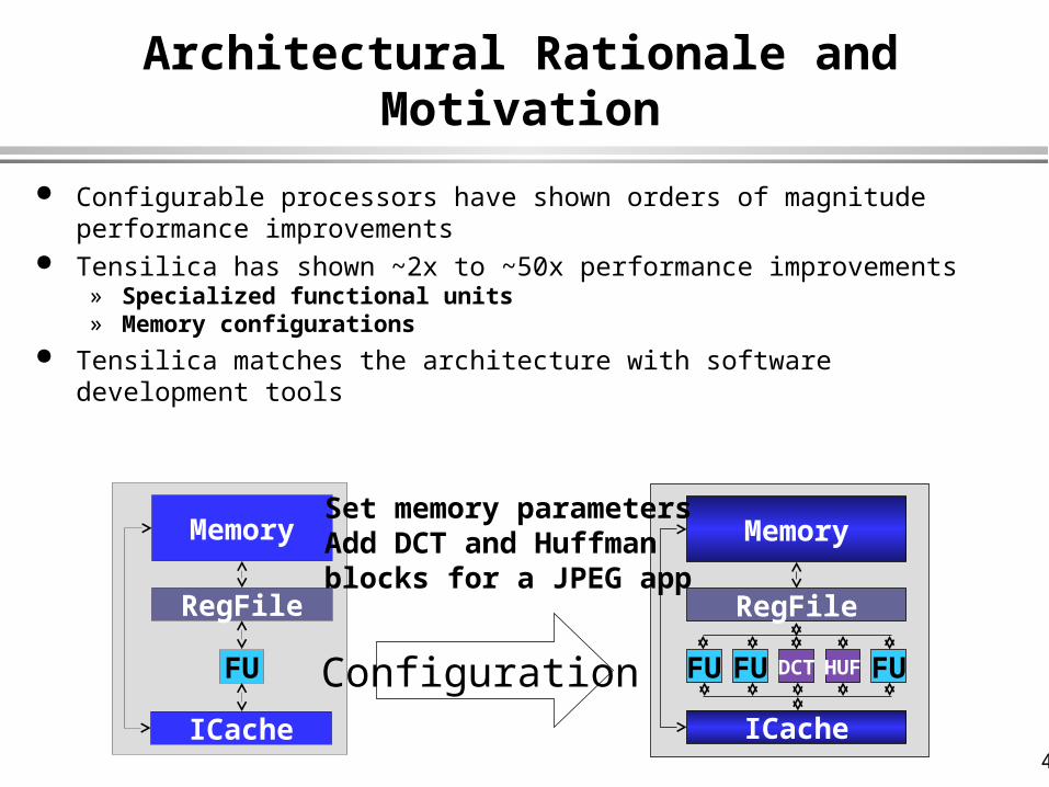
Architectural Rationale and Motivation
Configurable processors have shown orders of magnitude performance improvements
Tensilica has shown ~2x to ~50x performance improvements » Specialized functional units» Memory configurations
Tensilica matches the architecture with software development tools
FU
RegFile
Memory
ICache
FUFU
RegFile
Memory
ICache
HUFDCT FUConfiguration
Set memory parametersAdd DCT and Huffmanblocks for a JPEG app

46
Architectural Rationale and Motivation
In order to continue this performance improvement trend» Architectural features which exploit more concurrency are required» Heterogeneous configurations need to be made possible» Software development tools support new configuration options
FUFU
RegFile
Memory
ICache
HUFDCT FU
PE PE
PE PE
PE
PE
PE PE PE
FUFU FU
RegFile
Memory
ICache
DCTHUF
...begins tolook like aVLIW...
PE PE
PE PE
PE
PE
PE PE PE
...concurrent processesare required in orderto continue performanceimprovement trend...
...generic meshmay not suit theapplication’stopology...
PE PE
PE PE
PE
PE PE PE
...configurable VLIWPEs and network topology...

47
Architecture Goals
Provide template for the exploration of a range of architectures
Retarget compiler and simulator to the architecture
Enable compiler to exploit the architecture
Concurrency» Multiple instructions per processing element» Multiple threads per and across processing elements» Multiple processes per and across processing elements
Support for efficient computation» Special-purpose functional units, intelligent memory, processing elements
Support for efficient communication» Configurable network topology» Combined shared memory and message passing

48
Architecture Template
Prototyping template for array of processing elements» Configure processing element for efficient computation» Configure memory elements for efficient retiming» Configure the network topology for efficient communication
FUFU FU
RegFile
Memory
ICache
DCTHUFFUFU FU
RegFile
Memory
ICache
FU FU FUFU FU
RegFile
Memory
ICache
DCTHUF
Memory
RegFile
...configurePE...
...configurememoryelements...
...configure PEsand network tomatch the application...

49
Range of Architectures
Scalar Configuration EPIC Configuration EPIC with special FUs Mesh of HPL-PD PEs Customized PEs, network Supports a family of
architectures» Plan to extend the family with
the micro-architectural features presented
FU
Register File
Memory System
Instruction Cache

50
PE PE
PE PE
PE
PE
PE PE PE
FUFU FUFU FU
Register File
Memory System
Instruction Cache
Range of Architectures
Scalar Configuration EPIC Configuration EPIC with special FUs Mesh of HPL-PD PEs Customized PEs, network Supports a family of
architectures» Plan to extend the family with
the micro-architectural features presented

51
FUFU FFT
Register File
Memory System
Instruction Cache
DCTDES
Range of Architectures
Scalar Configuration EPIC Configuration EPIC with special FUs Mesh of HPL-PD PEs Customized PEs, network Supports a family of
architectures» Plan to extend the family with
the micro-architectural features presented

52
FUFU FFT
Register File
Memory System
Instruction Cache
DCTDES
Range of Architectures
Scalar Configuration EPIC Configuration EPIC with special FUs Mesh of HPL-PD PEs Customized PEs, network Supports a family of
architectures» Plan to extend the family with
the micro-architectural features presented
PE
PE PE
PE
PE
PE
PE PE PE

53
Range of Architectures
Scalar Configuration EPIC Configuration EPIC with special FUs Mesh of HPL-PD PEs Customized PEs, network Supports a family of
architectures» Plan to extend the family with
the micro-architectural features presented
PE PE
PE PE
PE
PE PE PE

54
Range of Architectures (Future)
Template support for such an architecture
Prototype architecture Software development
tools generated» Generate compiler» Generate simulator
SDRAMCtrl
MicroEngPCI
Interface
SRAMCtrl
SACore
MicroEng
MicroEng
MicroEng
MicroEng
MicroEng
MiniDCache
DCache
ICache
ScratchPad
SRAM
IX BusInterface
HashEngine
IXP1200 Network Processor (Intel)

55
The RAW Architecture
Slides prepared by Manish Vachhrajani

56
Outline RAW architecture
» Overview» Features» Benefits and Disadvantages
Compiling for RAW» Overview» Structure of the compiler» Basic block compilation» Other techniques

57
RAW Machine Overview
Scalable architecture without global interconnect
Constructed from Replicated Tiles» Each tile has a mP and a
switch» Interconnect via a static
and dynamic network

58
RAW Tiles
Simple 5 stage pipelined P w/ local PC(MIMD)
» Can contain configurable logic
Per Tile IMEM and DMEM, unlike other modern architectures
P contains ins. to send and recv. data
IMEM
DMEMPC
REGS
CL SMEM
Switch
PC

59
RAW Tiles(cont.)
Tiles have local switches» Implemented with a stripped down P» Static Network
– Fast, easy to implement– Need to know data transfers, source and destintation at
compile time» Dynamic Network
– Much slower and more complex– Allows for messages whose route is not known at compile
time

60
Configurable Hardware in RAW
Each tile Contains its own configurable hardware Each tile has several ALUs and logic gates that can operate at
bit/byte/word levels Configurable interconnect to wire componenets together Coarser than FPGA based implementations

61
Benefits of RAW Scalable
» Each tile is simple and replicated» No global wiring, so it will scale even if wire delay doesn’t» Short wires and simple tiles allow higher clock rates
Can target many forms of Parallelism Ease of design
» Replication reduces design overhead» Tiles are relatively simple designs» simplicity makes verification easier

62
Disadvantages of RAW Complex Compilation
» Full space-time compilation» Distributed memory system» Need sophisticated memory analysis to resolve “static
references” Software Complexity
» Low-level code is complex and difficult to examine and write by hand
Code Size?

63
Traditional Operations on RAW
How does one exploit the Raw architecture across function calls, especially in libraries?» Can we easily maintain portability with different tile counts?
Memory Protection and OS Services» Context switch overhead» Load on dynamic network for memory protection and virtual
memory?

64
Compiling for RAW machines
Determine available parallelism Determine placement of memory items Discover memory constraints
» Dependencies between parallel threads» Disambiguate memory references to allow for static access to
data elements» Trade-off memory dependence and Parallelism

65
Compiling for RAW(cont.)
Generate route instructions for switches» static network only
Generate message handlers for dynamic events» Speculative execution» Unpredictable memory references
Optimal partitioning algorithm is NP complete

66
Structure of RAWCC
Partition data to increase static accesses
Partition instructions to allow parallel execution
allocate data to tiles to minimize communication overhead
Traditional Dataflow Optimizations
Build CFG
MAPS System
Space-time scheduler
Source Language
RAW executable

67
The MAPS System
Manages memory to generate static promotions of data structures
For loop accesses to arrays uses modulo unrolling For data structures, uses SPAN analysis package to identify
potential references and partition memory» structures can be split across processing elements.

68
Space-Time Scheduler
For Basic Blocks» Maps instructions to processors» Maps scalar data to processors» Generates communication instructions» Schedules computation and communication
For overall CFG, performs control localization

69
Basic Block Orchestrator
All values are copied to the tiles that work on the data from the home tile
Within a Block, all access are local
At the end of a block, values are copied to home tiles
Initial Code Transformation
Instruction Partitioner
Global DataPartitioner
Data & Ins.Placer
Event Scheduler
Comm CodeGenerator

70
Initial Code Transformation
Convert Block to static single assignment form» removes false dependencies» Analagous to register renaming
Live on entry, and live on exit variables marked with dummy instructions» Allows for overlap of “stitch” code with useful work

71
Instruction Partitioner Partitions stream into multiple streams, one for each tile Clustering
» Partition instructions to minimize runtime considering only communication
Merging» Reduces cluster count to match tile count» Uses a heuristic based algorithm to achieve good balance and
low communication overhead
72
Global Data Partitioner
Partitions global data for assignment to home locations» Local data is copied at the start of a basic block
Summarize instruction stream’s data access pattern with affinity Maps instructions and data to virtual processors
» Map instructions, optimally place data based on affinity» Remap instructions with data placement knowledge» Repeat until local minima is reached
Only real data are mapped, not dummies formed in ICT

73
Data and Instruction Placer
Places data items onto physical tiles» driven by static data items
Places instructions onto tiles» Uses data information to determine cost
Takes into account actual model of communications network Uses a swap based greedy allocation

74
Event Scheduler
Schedules routing instructions as well as computation instructions in a basic block
Schedules instructions using a greedy list based scheduler Switch schedule is ensured to be deadlock free
» Allows tolerance of dynamic events
75
Control Flow
Control Localization» Certain branches are enveloped in macro instructions, and
the surrounding blocks merged» Allows branch to occur only on one tile
Global Branching» Done through target broadcast and local branching

76
Performance RAW achieves anywhere from 1.5 to 9 times speedup
depending on application and tile count Applications tested were particularly well suited to RAW Heavily dependent integer programs may do poorly(encryption,
etc.)) Depends on its ability to statically schedule and localize memory
accesses
77
Future Work
Use multisequential execution to run multiple applications simultaneously» Allow static communication between threads known at
compile time» Minimize dynamic overhead otherwise
Target ILP across branches more agressively Explore configurability vs. parallelism in RAW

78
Reconfigurable processors
Adapt the processor to the application
» special function units» special wiring between function
units Builds on FPGA technology
» FPGAs are inefficient– a multiplier built from an
FPGA is about 100x larger and 10x slower than a custom multiplier.
» Need to raise the granularity– configure ALUs, or whole
processors» Memory and communication are
usually the bottleneck– not addressed by configuring
a lot of ALUs Programming model
» Difficult to program» Verilog

79
SCOREStream Computation Organized for
Reconfigurable Execution
Eylon CaspiMichael ChuAndré DeHonRandy HuangJoseph YehJohn WawrzynekNicholas Weaver

80
Opportunity
High-throughput, regular operations can be mapped spatially onto FPGA-like
(programmable, spatial compute substrate) achieving higher performance
» (throughput per unit area) than conventional, programmable devices
» (e.g. processors)

81
Problem
Only have raw devices Solutions non-portable Solutions not scale to new hardware Device resources exposed to developer Little or no abstraction of implementations Composition of subcomponents hard/ad hoc No unifying computational model or run-time environment
82
Introduce: SCORE
Compute Model» virtualizes RC hardware resources» supports automatic scaling» supports dynamic program requirements efficiently» provides compositional semantics» defines runtime environment for programs

83
Viewpoint
SCORE (or something like it) is a necessary condition to enable automatic exploitation of new RC hardware as it becomes available.
Automatic exploitation is essential to making RC a long-term viable computing solution.

84
Outline Opportunity Problem Review
» related work» enabling hardware
Model» execution» programmer
Preliminary Results Challenges and Questions ahead
85
…borrows heavily from...
RC, RTR P+FPGA Dataflow Streaming Dataflow Multiprocessors Operating System (see working paper)
Tried to steal all the good ideas :-)
build a coherent model exploit strengths of RC

86
Enabling Hardware
High-speed, computational arrays» [250MHz, HSRA, FPGA’99]
Large, on-chip memories» [2Mbit, VLSI Symp. ‘99]» [allow microsecond reconfiguration]
Processor and FPGA hybrids» [GARP, NAPA, Triscend, etc.]

87
BRASS Architecture

88
Array Model

89
Platform Vision Hardware capacity scales up with each generation
» Faster devices» More computation» More memory
With SCORE, old programs should run on new hardware» and exploit the additional capacity automatically

90
Example: SCORE Execution

91
Spatial Implementation

92
Serial Implementation

93
Summary: Elements of a multiprocessing system
General purpose/special purpose Granularity - capability of a basic module Topology - interconnection/communication geometry Nature of coupling - loose to tight Control-data mechanisms Task allocation and routing methodology Reconfigurable
» Computation» Interconnect
Programmer’s model/Language support/ models of computation
Implementation - IC, Board, Multiboard, Networked Performance measures and objectives
[After E. V. Krishnamurty - Chapter 5

94
Conclusions
Portions of multi/parallel processing have become successful» Pipelining ubiquitious» Superscalar ubiquitious» VLIW successful in DSP, Multimedia - GPP?
Silicon capability re-invigorating multiprocessor research» GPP - Flash, Hydra, RAW» SPP - Intel IXP 1200, IRAM/VIRAM, Mescal
Reconfigurable computing has found a niche in wireless communications
Problem of programming models, languages, computational models etc. for multiprocessors still largely unsolved
Recommended