Implementing Cisco Edge Network Security Solutions
300-206 (SENSS) =Firewall (642-618)
Mohamed Abouelenein Attia [10-04-2015] [SENSS]
1 | P a g e Mohamed Abou Elenein
Contents
Port security .................................................................................................................. 2
DHCP snooping .............................................................................................................. 3
Dynamic ARP inspection ............................................................................................... 4
Source Guard ................................................................................................................. 6
Private VLANs ................................................................................................................ 7
Protected ports .............................................................................................................. 9
VACLS,PACLS&MACsec ................................................................................................ 10
Remote Management ................................................................................................. 11
RSA SSH Authentication .............................................................................................. 12
SNMPV3-CPPr .............................................................................................................. 14
IACLs ............................................................................................................................. 15
URPF ............................................................................................................................. 16
Net-flow ......................................................................................................................... *
NAT&PAT ..................................................................................................................... 17
Zone based firewalls ................................................................................................... 18
AAA .............................................................................................................................. 21
Best Practices............................................................................................................... 23
ASA CLI Layer 3-4 ......................................................................................................... 25
ASA CLI Layer 5-7 ......................................................................................................... 28
ASA packet capture ..................................................................................................... 30
Botnet Filtering ............................................................................................................ 33
Context Directory Agent ............................................................................................. 36
Security Virtualization(IPS&IDS) ................................................................................. 39
ISE ................................................................................................................................. 42
ACS ............................................................................................................................... 44
Reference ..................................................................................................................... 48
2 | P a g e Mohamed Abou Elenein
Port security
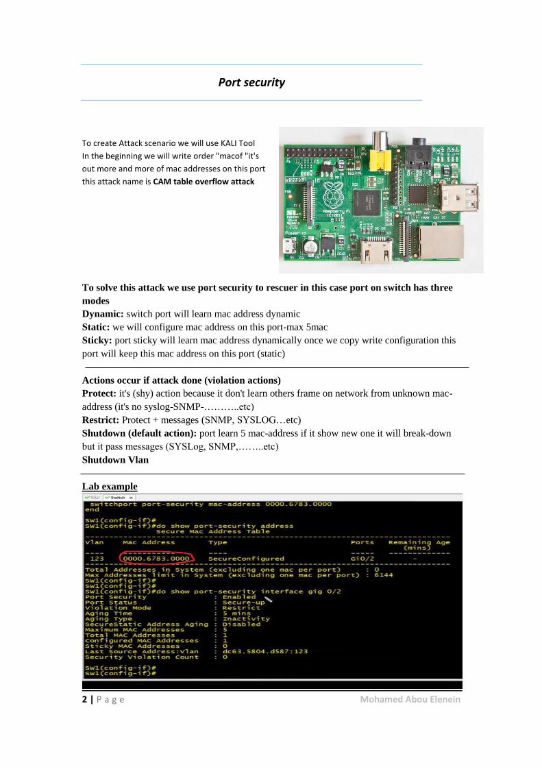
To create Attack scenario we will use KALI Tool
In the beginning we will write order "macof "it's
out more and more of mac addresses on this port
this attack name is CAM table overflow attack
To solve this attack we use port security to rescuer in this case port on switch has three
modes
Dynamic: switch port will learn mac address dynamic
Static: we will configure mac address on this port-max 5mac
Sticky: port sticky will learn mac address dynamically once we copy write configuration this
port will keep this mac address on this port (static)
Actions occur if attack done (violation actions)
Protect: it's (shy) action because it don't learn others frame on network from unknown mac-
address (it's no syslog-SNMP-………..etc)
Restrict: Protect + messages (SNMP, SYSLOG…etc)
Shutdown (default action): port learn 5 mac-address if it show new one it will break-down
but it pass messages (SYSLog, SNMP,……..etc)
Shutdown Vlan
Lab example
3 | P a g e Mohamed Abou Elenein
interface GigabitEthernet 0/2
switchport access vlan 123
switchport mode access
switchport port-security maximum 5
swishport port-security
swishport port-security aging time 5
swishport port-security violation restrict
swishport port-security aging type inactivity
swishport port-security mac-address 0000.6783.0000
------------------------------------------
show swishport port-security address
show swishport port-security gig 0/2
------------------------------------------
switchport trunk encapsulation dot1Q
switchport mode trunk
switchport port-security maximum 50 vlan 123
swishport port-security
DHCP Snooping
What's DHCP?
The Dynamic Host Configuration Protocol (DHCP) is a
standardized network protocol used on Internet Protocol
(IP) networks for dynamically distributing network
configuration.
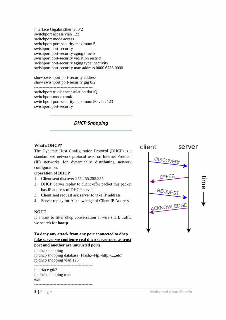
Operation of DHCP
1. Client sent discover 255.255.255.255
2. DHCP Server replay to client offer packet this packet
has IP address of DHCP server
3. Client sent request ask server to take IP address
4. Server replay for Acknowledge of Client IP Address
NOTE
If I want to filter dhcp conversation at wire shark traffic
we search for bootp
To deny any attack from any port connected to dhcp
fake server we configure real dhcp server port as trust
port and another are untrusted ports.
ip dhcp snooping
ip dhcp snooping database (Flash:/-Ftp:-http:-.....etc)
ip dhcp snooping vlan 123
------------------------------------------
interface g0/3
ip dhcp snooping trust
exit
------------------------------------------
4 | P a g e Mohamed Abou Elenein
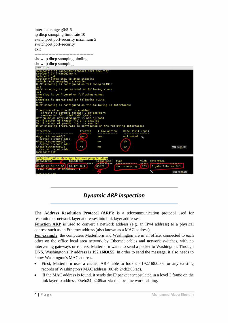
interface range g0/5-6
ip dhcp snooping limit rate 10
switchport port-security maximum 5
switchport port-security
exit
------------------------------------------
show ip dhcp snooping binding
show ip dhcp snooping
Dynamic ARP inspection
The Address Resolution Protocol (ARP): is a telecommunication protocol used for
resolution of network layer addresses into link layer addresses.
Function ARP is used to convert a network address (e.g. an IPv4 address) to a physical
address such as an Ethernet address (also known as a MAC address).
For example, the computers Matterhorn and Washington are in an office, connected to each
other on the office local area network by Ethernet cables and network switches, with no
intervening gateways or routers. Matterhorn wants to send a packet to Washington. Through
DNS, Washington's IP address is 192.168.0.55. In order to send the message, it also needs to
know Washington's MAC address.
First, Matterhorn uses a cached ARP table to look up 192.168.0.55 for any existing
records of Washington's MAC address (00:eb:24:b2:05:ac).
If the MAC address is found, it sends the IP packet encapsulated in a level 2 frame on the
link layer to address 00:eb:24:b2:05:ac via the local network cabling.
5 | P a g e Mohamed Abou Elenein
If the cache did not produce a result for 192.168.0.55, Matterhorn has to send a broadcast
ARP message (destination FF:FF:FF:FF:FF:FF MAC address which is accepted by all
computers) requesting an answer for 192.168.0.55. Washington responds with its MAC
address (and it's IP). Washington may insert an entry for Matterhorn into its own ARP
table for future use. The response information is cached in Matterhorn's ARP table and
the message can now be sent.
NOTE
If I want to filter ARP conversation at wire shark traffic we search for arp
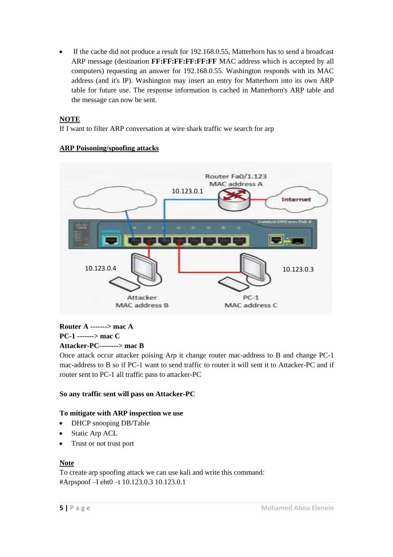
ARP Poisoning/spoofing attacks
Router A -------> mac A
PC-1 -------> mac C
Attacker-PC--------> mac B
Once attack occur attacker poising Arp it change router mac-address to B and change PC-1
mac-address to B so if PC-1 want to send traffic to router it will sent it to Attacker-PC and if
router sent to PC-1 all traffic pass to attacker-PC
So any traffic sent will pass on Attacker-PC
To mitigate with ARP inspection we use
DHCP snooping DB/Table
Static Arp ACL
Trust or not trust port
Note
To create arp spoofing attack we can use kali and write this command:
#Arpspoof –I eht0 –t 10.123.0.3 10.123.0.1
10.123.0.1
10.123.0.3 10.123.0.4
6 | P a g e Mohamed Abou Elenein
ip arp inspection vlan 123
show ip arp inspection vlan 123
int gig 0/1
switchport mode trunk
ip arp inspection trust
int gig 0/2
switchport mode access
ip arp inspection limit rate 10
------------------------------------------
arp access-list OUR-ARP-ACL
permit ip host 10.123.0.1 mac host 001f.9e00.ee89
exit
ip arp inspection filter OUR-ARP-ACL vlan 123
--------------------------------------------
show ip arp inspection statistics vlan 123
show ip arp inspection vlan 123
ip arp inspection validate scr-mac dst-mac ip
Source Guard
IP Spoofing attack
It's same of mac-address attack but it replace mac to ip
So we can deny this attack by ip source guard
int gig 0/2
ip verify source port-security
exit
ip source binding B827.EB51.1AF6 vlan 123 10.123.0.50 interface gig 0/2
show ip verify source
show ip source binding
7 | P a g e Mohamed Abou Elenein
Private VLANs
Also known as port isolation Private VLAN divides a VLAN (Primary) into sub-VLANs
(Secondary) while keeping existing IP subnet and layer 3 configuration. A regular VLAN is a
single broadcast domain, while private VLAN partitions one broadcast domain into multiple
smaller broadcast subdomains.
Primary VLAN: Simply the original VLAN. This type of VLAN is used to forward frames
downstream to all Secondary VLANs.
Secondary VLAN: Secondary VLAN is configured with one of the following types:
Isolated: Any switch ports associated with an Isolated VLAN can reach the primary
VLAN, but not any other Secondary VLAN. In addition, hosts associated with the same
Isolated VLAN cannot reach each other. There can be multiple Isolated VLANs in one
Private VLAN domain (which may be useful if the VLANs need to use distinct paths for
security reasons); the ports remain isolated from each other within each VLAN.[1]
Community: Any switch ports associated with a common community VLAN can
communicate with each other and with the primary VLAN but not with any other
secondary VLAN. There can be multiple distinct community VLANs within one Private
VLAN domain.
There are mainly three types of ports in a Private VLAN:
Promiscuous port (P-Port): The switch port connects to a router, firewall or other
common gateway device. This port can communicate with anything else connected to the
primary or any secondary VLAN. In other words, it is a type of a port that is allowed to
send and receive frames from any other port on the VLAN.
Isolated Port (I-Port): Connects to the regular host that resides on isolated VLAN. This
port communicates only with P-Ports.
Community Port (C-Port): Connects to the regular host that resides on community
VLAN. This port communicates with P-Ports and ports on the same community VLAN.
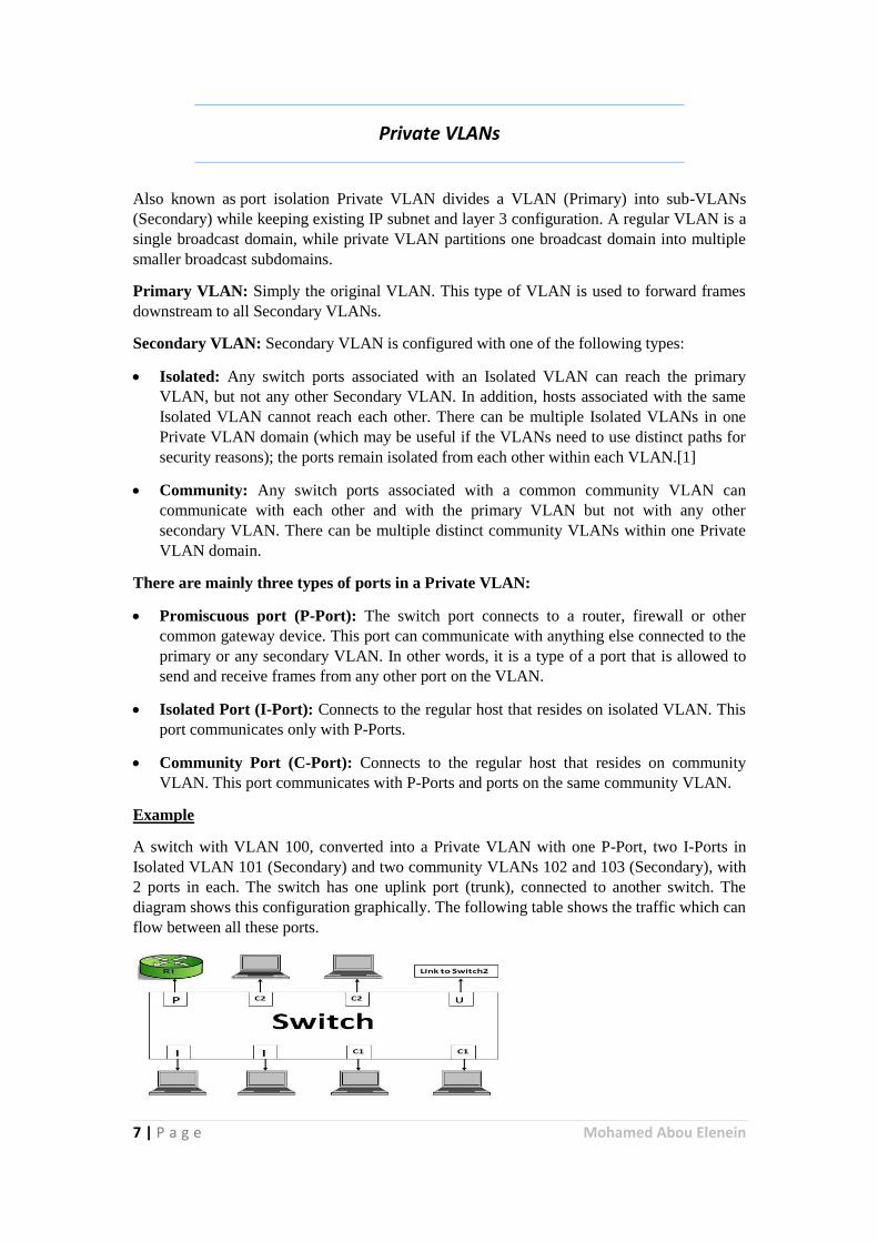
Example
A switch with VLAN 100, converted into a Private VLAN with one P-Port, two I-Ports in
Isolated VLAN 101 (Secondary) and two community VLANs 102 and 103 (Secondary), with
2 ports in each. The switch has one uplink port (trunk), connected to another switch. The
diagram shows this configuration graphically. The following table shows the traffic which can
flow between all these ports.
8 | P a g e Mohamed Abou Elenein
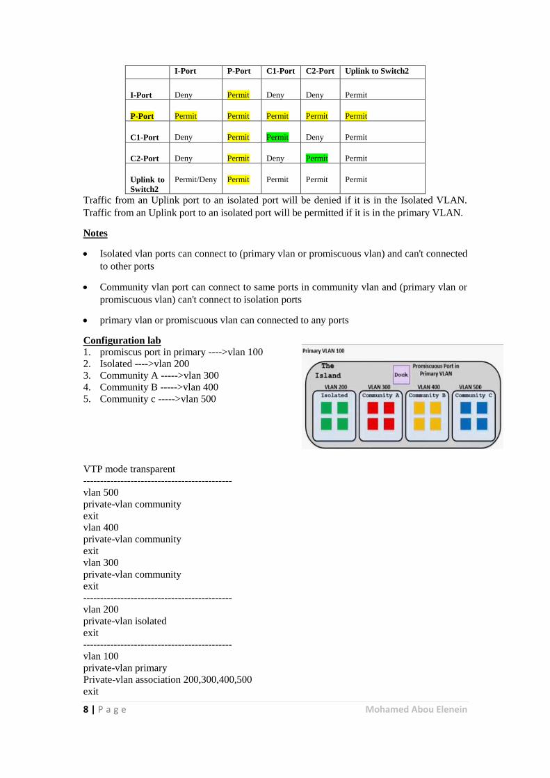
I-Port P-Port C1-Port C2-Port Uplink to Switch2
I-Port Deny Permit Deny Deny Permit
P-Port Permit Permit Permit Permit Permit
C1-Port Deny Permit Permit Deny Permit
C2-Port Deny Permit Deny Permit Permit
Uplink to
Switch2
Permit/Deny Permit Permit Permit Permit
Traffic from an Uplink port to an isolated port will be denied if it is in the Isolated VLAN.
Traffic from an Uplink port to an isolated port will be permitted if it is in the primary VLAN.
Notes
Isolated vlan ports can connect to (primary vlan or promiscuous vlan) and can't connected
to other ports
Community vlan port can connect to same ports in community vlan and (primary vlan or
promiscuous vlan) can't connect to isolation ports
primary vlan or promiscuous vlan can connected to any ports
Configuration lab
1. promiscus port in primary ---->vlan 100
2. Isolated ---->vlan 200
3. Community A ----->vlan 300
4. Community B ----->vlan 400
5. Community c ----->vlan 500
VTP mode transparent
--------------------------------------------
vlan 500
private-vlan community
exit
vlan 400
private-vlan community
exit
vlan 300
private-vlan community
exit
--------------------------------------------
vlan 200
private-vlan isolated
exit
--------------------------------------------
vlan 100
private-vlan primary
Private-vlan association 200,300,400,500
exit
9 | P a g e Mohamed Abou Elenein
--------------------------------------------
int gig 0/11
switchport mode private-vlan promiscuous
switchport private-vlan mapping 100 200,300,400,500
exit
--------------------------------------------
int rang gig 0/12-13
switchport mode private-vlan host
switchport private-vlan host-association 100 200
--------------------------------------------
int rang gig 0/14
switchport mode private-vlan host
switchport private-vlan host-association 100 300
exit
int rang gig 0/15
switchport mode private-vlan host
switchport private-vlan host-association 100 400
exit
int rang gig 0/16
switchport mode private-vlan host
switchport private-vlan host-association 100 500
exit
--------------------------------------------
show vlan private-vlan
show int gig 0/11 switchport
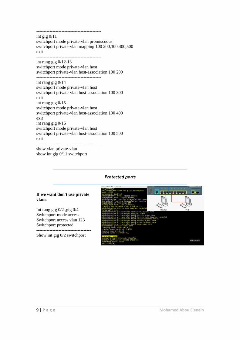
Protected ports
If we want don't use private
vlans:
Int rang gig 0/2 ,gig 0/4
Switchport mode access
Switchport access vlan 123
Switchport protected
-------------------------------------
Show int gig 0/2 switchport

10 | P a g e Mohamed Abou Elenein
VACLS,PACLS&MACsec
Filter traffic by use
VACLS: Vlan Access control-list (Vlan-map)
PACLS: Port based Access control list
MACSEC: To encrypt layer 2 between two switches L2 hop by hop encryption (CTS or SAP
PMK)
ip access-list extended UNWANTED-IP-PORT
permit tcp 10.1.2.0 0.0.0.255 any eq 456
permit udp 10.1.2.0 0.0.0.255 any eq 456
exit
-----------------------
mac access-list extended UNWANTED-MAC
permit host 0000.1234.5678 any
exit
------------------------
ip access-list extended ALLOW_TRAFFIC
permit ip any any
exit
------------------------
Vlan access-map VACL 10
match ip address UNWANTED-IP-PORT
action drop
exit
-------------------------
Vlan access-map VACL 20
match mac address UNWANTED-MAC
action drop
exit
-------------------------
Vlan access-map VACL 30
match mac address ALLOWED-TRAFFIC
action forward
exit
-------------------------
vlan filter VACL vlan 55
-------------------------
ip access-list extended NO-PING-TO-11
deny icmp any host 10.123.0.11
permit ip any any
---------------------------
int gig 0/2
ip access-group NO-PING-TO-11 in
exit
-----------------------------
int gig 0/26
11 | P a g e Mohamed Abou Elenein
cts manual
sap pmk ABCD
show cts int
Remote Management
We can manage by using cisco configuration professional (CCP) hostname R1
ip domain-name CBTNuggets.com
security password min-length 6
username admin privilege 15 secret cisco123
enable secret cisco123
service password-encryption
crypto key generate rsa modulus 2048 label OUR-RSA-KEYS
show crypto key mypubkey rsa
-----------------
ip ssh version 2
ip ssh time-out 30
ip ssh authentication-retries 5
---------------------------------
ip access-list standard 5
permit host 10.1.0.25
permit host 192.168.1.23
deny any log
exit
-----------------------
no ip http server
ip http secure-server
ip http authentication local
ip http acces-class 5
--------------------
line vty 0 15
transport input ssh
login local
access-class 5 in
exit
--------------------
login delay 5
login block-for 30 attempts 3 within 60
12 | P a g e Mohamed Abou Elenein
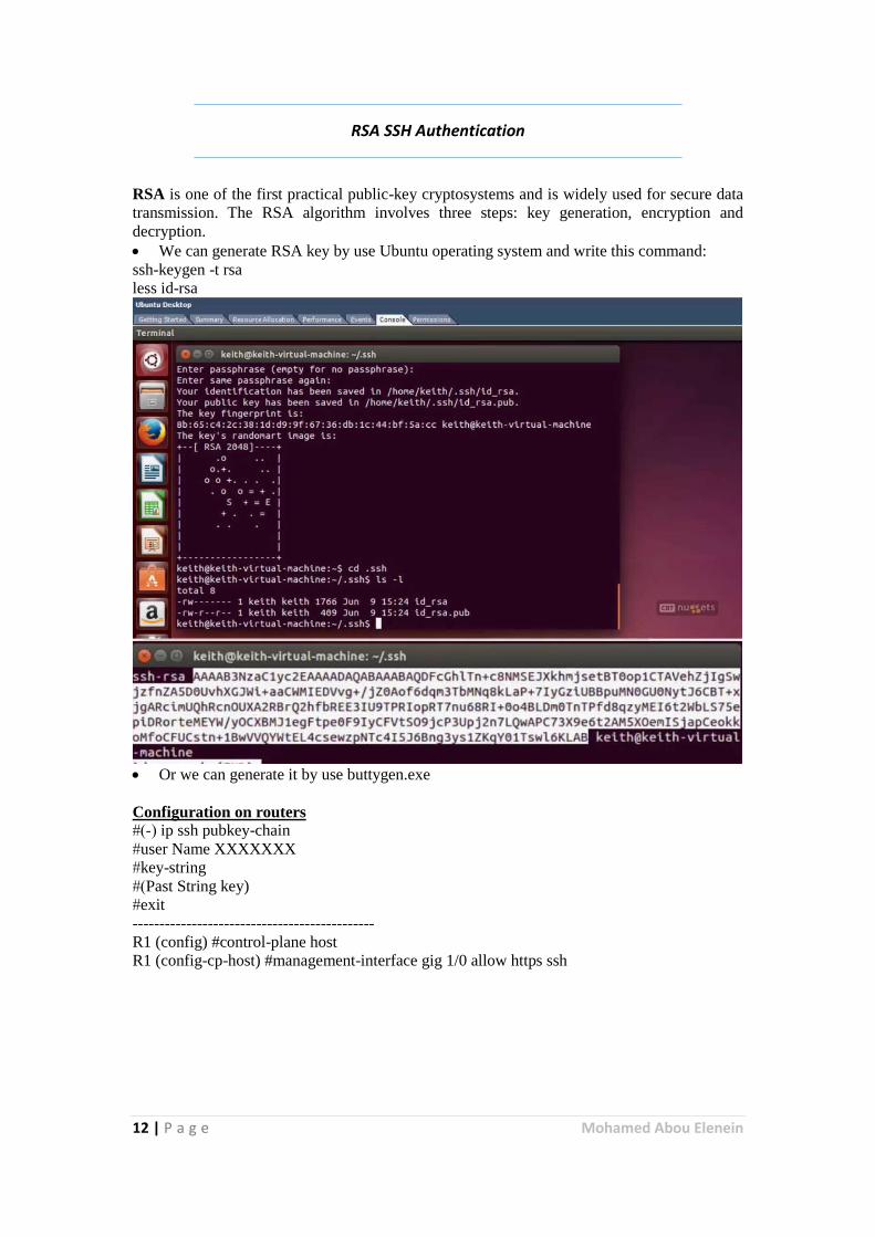
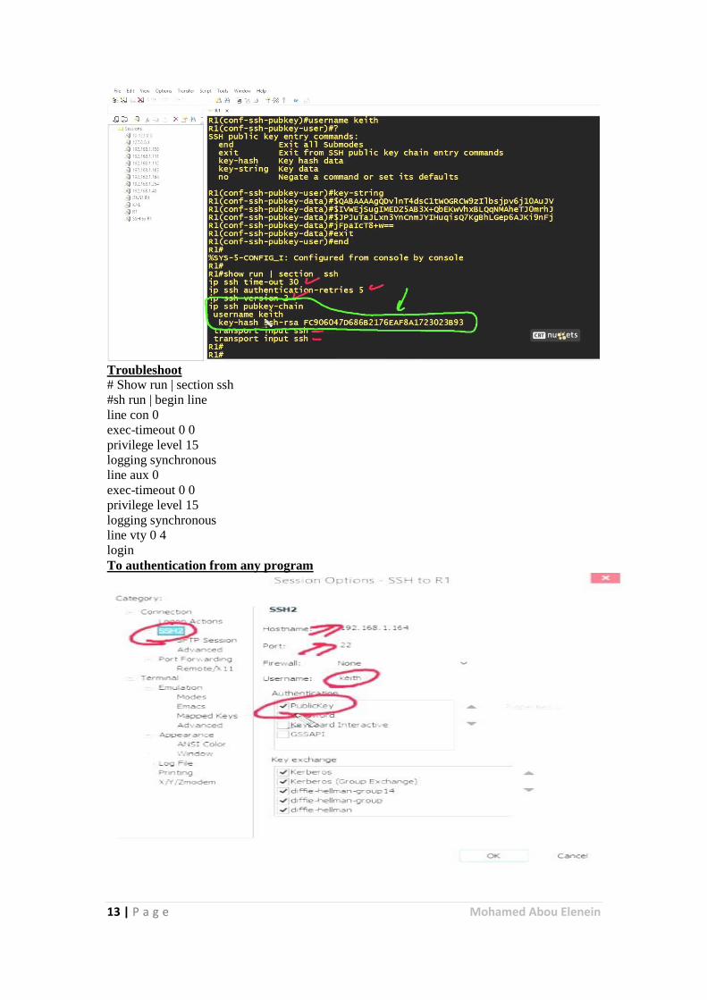
RSA SSH Authentication
RSA is one of the first practical public-key cryptosystems and is widely used for secure data
transmission. The RSA algorithm involves three steps: key generation, encryption and
decryption.
We can generate RSA key by use Ubuntu operating system and write this command:
ssh-keygen -t rsa
less id-rsa
Or we can generate it by use buttygen.exe
Configuration on routers
(-#) ip ssh pubkey-chain
#user Name XXXXXXX
#key-string
#)Past String key)
#exit
---------------------------------------------
R1 (config) #control-plane host
R1 (config-cp-host) #management-interface gig 1/0 allow https ssh
13 | P a g e Mohamed Abou Elenein
Troubleshoot
# Show run | section ssh
#sh run | begin line
line con 0
exec-timeout 0 0
privilege level 15
logging synchronous
line aux 0
exec-timeout 0 0
privilege level 15
logging synchronous
line vty 0 4
login
To authentication from any program
14 | P a g e Mohamed Abou Elenein
NTP&SNMPV3 SYSLOG and CPPR (Control Plan Protection)
Control plan protection
Class maps
Policy maps
Service policy (https,SSH,……etc.)
Simple Network Management Protocol (SNMP):
Is an "Internet-standard protocol for managing devices on IP networks". Devices that
typically support SNMP include routers, switches, servers, workstations, printers, modem
racks and more.
SNMP version 1: the oldest flavor. Easy to set up – only requires a plaintext community.
The biggest downsides are that it does not support 64 bit counters, only 32 bit counters,
and that it has little security. A community string sent in plaintext, possibly from a
restricted range of allowed IP addresses, is as good as the security gets. In other words, no
security from someone with access to the network – such a person will be able to see the
community string in plaintext, and spoofing a UDP packet’s source IP is trivial.
SNMP version 2c: in practical terms, v2c is identical to version 1, except it adds support
for 64 bit counters. This matters, especially for interfaces. Even a 1Gbps interface can
wrap a 32 bit counter in 34 seconds. Which means that a 32 bit counter being polled at
one minute intervals is useless, as it cannot tell the difference between successive values
of 30, 40 due to the fact that only 10 octets were sent in that minute, or 30, 40 due to the
fact that 4294967306 (2^32 +10) octets were sent in that minute.
SNMP version 3: adds security to the 64 bit counters. SNMP version 3 adds both
encryption and authentication, which can be used together or separately. Setup is more
complex than just defining a community string – but then, what security is not? But if
you require security, this is the way to do it.
Syslog
Is a widely used standard for message logging. It permits separation of the software that
generates messages, the system that stores them, and the software that reports and analyzes
them.
Network Time Protocol (NTP) Is a networking protocol for clock synchronization between computer systems over packet-
switched, variable-latency data networks.
R1 (config) #ntp server 10.10.10.100
Show ntp sta
Show ntp associations detail
---------------------------------------
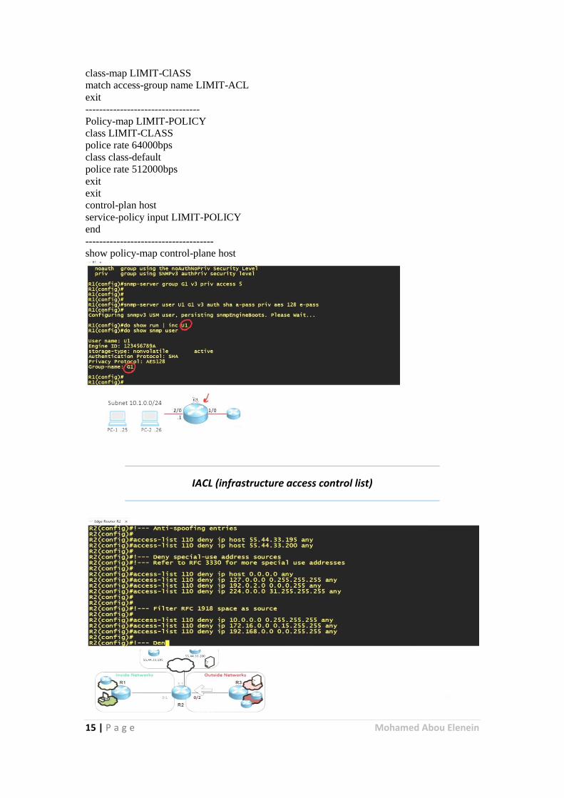
Snmp-server group G1 V3 priv access 5
Snmp-server user v1 g1v3 auth sha a-pass priv aes 128 e-pass
Snmp-server host 192168.1.23 traps version 3 auth v1
---------------------------------------- -------------------------------------- ip access-list extended LIMIT-ACL
permit udp any any eq snmp
permit tcp any any eq 22
exit
--------------------------------
15 | P a g e Mohamed Abou Elenein
class-map LIMIT-ClASS
match access-group name LIMIT-ACL
exit
---------------------------------
Policy-map LIMIT-POLICY
class LIMIT-CLASS
police rate 64000bps
class class-default
police rate 512000bps
exit
exit
control-plan host
service-policy input LIMIT-POLICY
end
-------------------------------------
show policy-map control-plane host
IACL (infrastructure access control list)
16 | P a g e Mohamed Abou Elenein
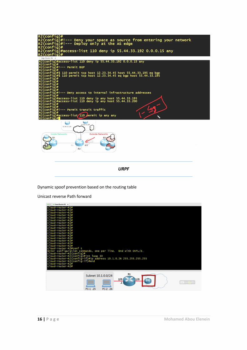
URPF
Dynamic spoof prevention based on the routing table
Unicast reverse Path forward
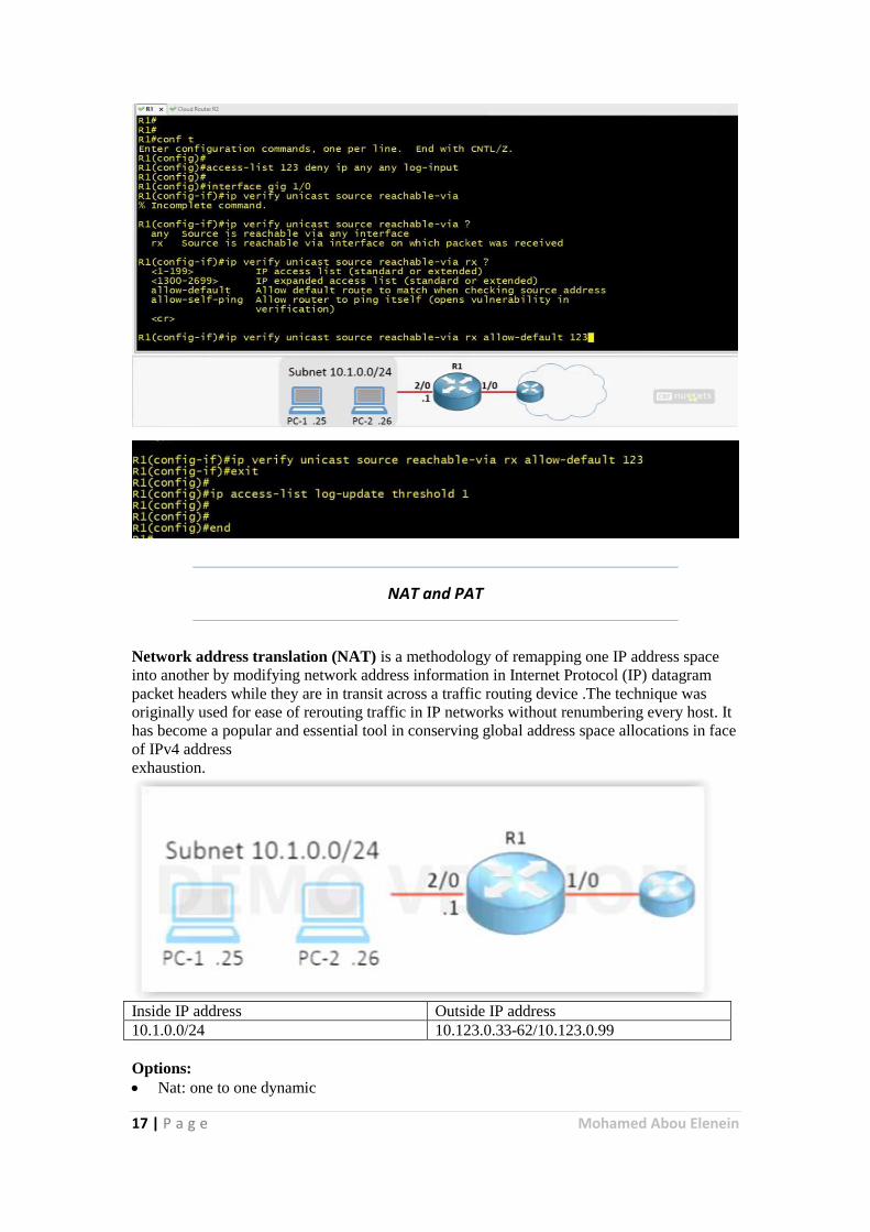
17 | P a g e Mohamed Abou Elenein
NAT and PAT
Network address translation (NAT) is a methodology of remapping one IP address space
into another by modifying network address information in Internet Protocol (IP) datagram
packet headers while they are in transit across a traffic routing device .The technique was
originally used for ease of rerouting traffic in IP networks without renumbering every host. It
has become a popular and essential tool in conserving global address space allocations in face
of IPv4 address
exhaustion.
Inside IP address Outside IP address
10.1.0.0/24 10.123.0.33-62/10.123.0.99
Options:
Nat: one to one dynamic
18 | P a g e Mohamed Abou Elenein
PAT: one to many Dynamic
NAT: one to one static
PAT: Port forwarding static
General configuration
Access-list 10 permit 10.1.0.0 0.0.0.255
Int gi 1/0
Ip nat outside
Exit
Int gi 2/0
Ip nat inside
Exit
Nat: one to one dynamic:
Ip nat pool our-Nat-Pool 10.123.0.33 10.123.0.62 prefix-length 27
Ip nat inside source list 10 pool our-Nat-Pool
PAT: one to many Dynamic
Ip nat inside source list 10 int gi 1/0 overload
NAT: one to one static
Ip nat inside source static 10.1.0.25 10.123.0.25
PAT: Port forwarding static
Ip nat inside source tcp 10.1.0.50 80 10.123.0.99 80 extendable
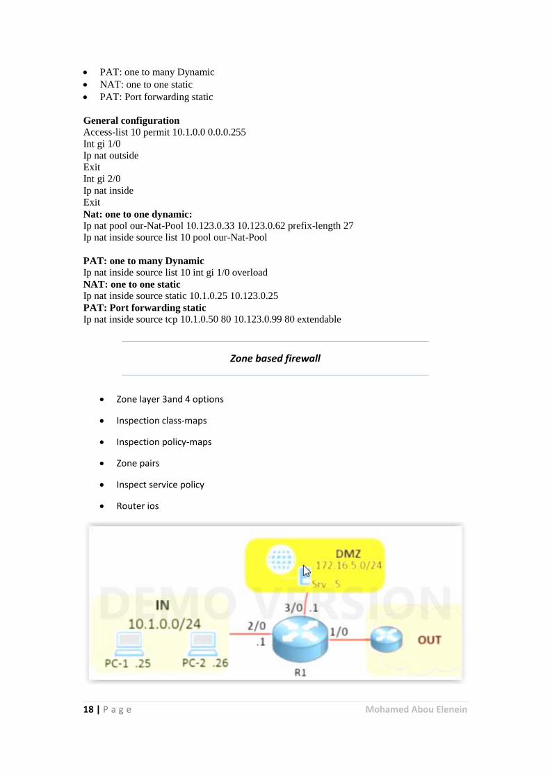
Zone based firewall
Zone layer 3and 4 options
Inspection class-maps
Inspection policy-maps
Zone pairs
Inspect service policy
Router ios
19 | P a g e Mohamed Abou Elenein
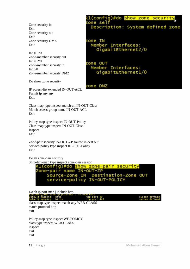
Zone security in
Exit
Zone security out
Exit
Zone security DMZ
Exit
Int gi 1/0
Zone-member security out
Int gi 2/0
Zone-member security in
Int 3/0
Zone-member security DMZ
Do show zone security
IP access-list extended IN-OUT-ACL
Permit ip any any
Exit
Class-map type inspect match-all IN-OUT-Class
Match access-group name IN-OUT-ACL
Exit
Policy-map type inspect IN-OUT-Policy
Class-map type inspect IN-OUT-Class
Inspect
Exit
Zone-pair security IN-OUT-ZP source in dest out
Service-policy type inspect IN-OUT-Policy
Exit
Do sh zone-pair security
Sh policy-map type inspect zone-pair session
Do sh ip port-map | include http
class-map type inspect match-any WEB-CLASS
match protocol http
exit
Policy-map type inspect WE-POLICY
class type inspect WEB-CLASS
inspect
exit
exit
20 | P a g e Mohamed Abou Elenein
Zone-pair security OUT-DMZ-ZP source OUT dest DMZ
Service-policy type inspect WE-POLICY
Exit
Application layer options
App inspect class-map
App inspect Policy-maps
Parameter-map type rgex com
Pattern .+\.[Cc][Oo][Mm]
Exit
Class-map type inspect http match-any BAD-HTTP-Class
Match request uri regex com
Match request protocol-violation
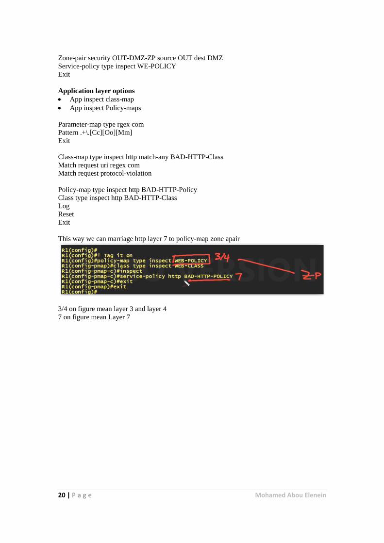
Policy-map type inspect http BAD-HTTP-Policy
Class type inspect http BAD-HTTP-Class
Log
Reset
Exit
This way we can marriage http layer 7 to policy-map zone apair
3/4 on figure mean layer 3 and layer 4
7 on figure mean Layer 7
21 | P a g e Mohamed Abou Elenein
AAA
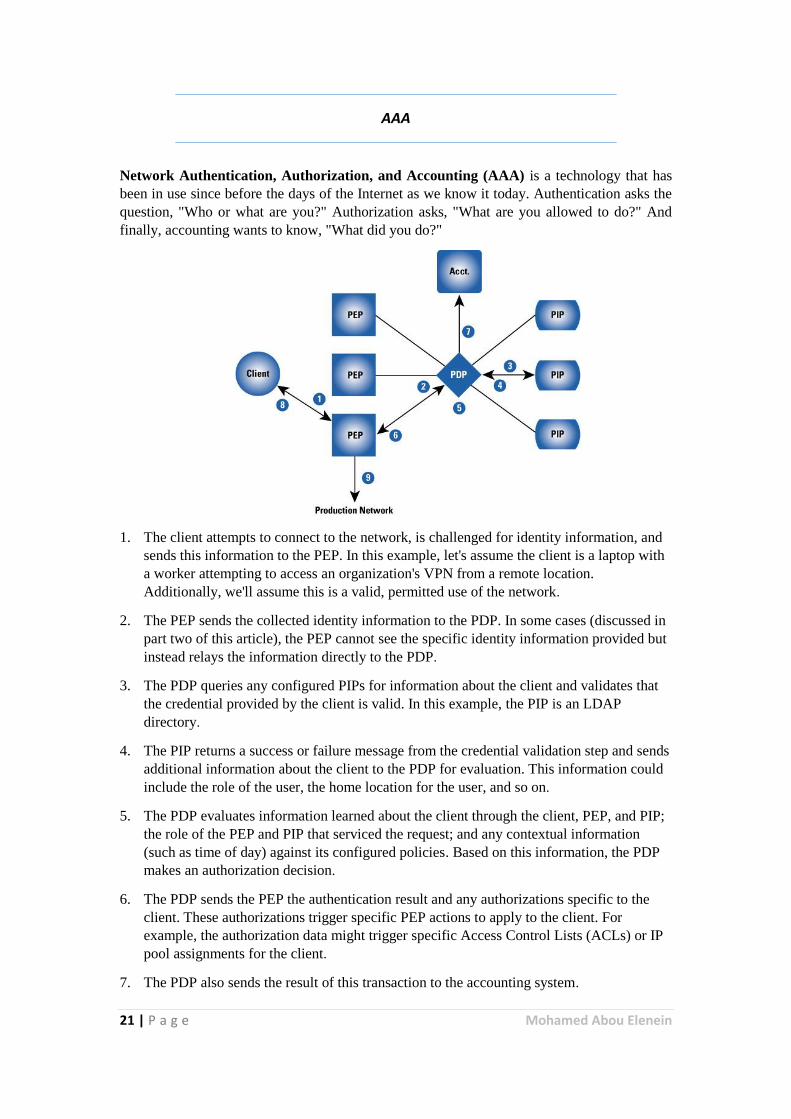
Network Authentication, Authorization, and Accounting (AAA) is a technology that has
been in use since before the days of the Internet as we know it today. Authentication asks the
question, "Who or what are you?" Authorization asks, "What are you allowed to do?" And
finally, accounting wants to know, "What did you do?"
1. The client attempts to connect to the network, is challenged for identity information, and
sends this information to the PEP. In this example, let's assume the client is a laptop with
a worker attempting to access an organization's VPN from a remote location.
Additionally, we'll assume this is a valid, permitted use of the network.
2. The PEP sends the collected identity information to the PDP. In some cases (discussed in
part two of this article), the PEP cannot see the specific identity information provided but
instead relays the information directly to the PDP.
3. The PDP queries any configured PIPs for information about the client and validates that
the credential provided by the client is valid. In this example, the PIP is an LDAP
directory.
4. The PIP returns a success or failure message from the credential validation step and sends
additional information about the client to the PDP for evaluation. This information could
include the role of the user, the home location for the user, and so on.
5. The PDP evaluates information learned about the client through the client, PEP, and PIP;
the role of the PEP and PIP that serviced the request; and any contextual information
(such as time of day) against its configured policies. Based on this information, the PDP
makes an authorization decision.
6. The PDP sends the PEP the authentication result and any authorizations specific to the
client. These authorizations trigger specific PEP actions to apply to the client. For
example, the authorization data might trigger specific Access Control Lists (ACLs) or IP
pool assignments for the client.
7. The PDP also sends the result of this transaction to the accounting system.
22 | P a g e Mohamed Abou Elenein
8. The PEP applies the authorization profile learned from the PDP and sends the
"authentication successful" message to the client. The PEP can also be configured to send
accounting information on this new connection to the accounting and reporting system.
9. The client accesses the production network through the PEP.
Used for RBAC (Roll base access control) and centralized management
AAA servers same
ISE
ACS
RADIUS
This servers use protocols same radius and tacacs+
Extended TACACS (XTACACS) is a proprietary extension to TACACS introduced by
Cisco Systems in 1990 without backwards compatibility to the original protocol. TACACS
and XTACACS both allow a remote access server to communicate with an authentication
server in order to determine if the user has access to the network.
TACACS is defined in RFC 1492, and uses (either TCP or UDP) port 49 by default.
TACACS allows a client to accept a username and password and send a query to a TACACS
authentication server, sometimes called a TACACS daemon or simply TACACSD.
TACACSD uses TCP and usually runs on port 49. It would determine whether to accept or
deny the authentication request and send a response back.
Terminal Access Controller Access-Control System Plus (TACACS+) is a protocol developed
by Cisco and released as an open standard beginning in 1993. Although derived from
TACACS, TACACS+ is a separate protocol that handles authentication, authorization, and
accounting (AAA) services. TACACS+ and other flexible AAA protocols have largely
replaced their predecessors.
TACACS+ and RADIUS have generally replaced TACACS and XTACACS in more recently
built or updated networks. TACACS+ is an entirely new protocol and is not compatible with
its predecessors, TACACS and XTACACS. TACACS+ uses TCP (while RADIUS operates
over UDP). Since TACACS+ uses the authentication, authorization, and accounting (AAA)
architecture, these separate components of the protocol can be segregated and handled on
separate servers
aaa new-model
username bob1 privilege 15 secret cisco123
aaa authentication login M-LOg group tacacs+ local
aaa authorization exec M-EXEC group tacacs+ local
aaa authorization command 1 M-LVL-1 group tacacs+ local
aaa authorization commands M-LVL-15 group tacaces+ local
aaa authorization config-commands
aaa accounting exec M-ACCT-EXEC start-stop group tacacs+
aaa accounting commands 1 M-1-ACCT start-stop group tacacs+
aaa accounting commands 15 M-15-ACCT start-stop group tacacs+
tacaces-server host 192.168.1.55
tacaces-server key cisco123
23 | P a g e Mohamed Abou Elenein
do test aaa group tacaces+ bob1 cisco123 legacy
line vty 0 15
login authentication M-LOG
authorization exec M-EXEC
accounting exec M-ACCT-EXEC
authorization commands 1 M-LVL-1
authorization commands 15 M-LVL-15
accounting commands 1 M-1-ACCT
accounting commands 15 M-15-ACCT
end
dubug tacacs
debug aaa
ssh -I bob1 -v 2 10.123.0.4
show ssh
Best Practices
auto archive configuration
archive
path tftp://192.168.1.23/$h
time-period 60
write-memory
end
sh archive
Secure Boot set
secure boot-image
secure boot-config
show users
Routing protocol Authentication
router bgb 123
neighbor 192.168.1.50 remote-as 555
neighbor 192.168.1.50 ttl-security hops 2
neighbor 192.168.1.50 password cisco123
exit
router ospf 1
area 0 authentication message-digest
exit
int gig 1/0
ip ospf message-digest-key 1 md5 cisco123
exit
24 | P a g e Mohamed Abou Elenein
HSRP/GLBP authentication
int gig 1/0
standby 1 authen md5 key-string cisco123
glbp 1 authen md5 key-string cisco123
exit
No source routing information
no ip source-route
No IP options allowed
ip options drop
end
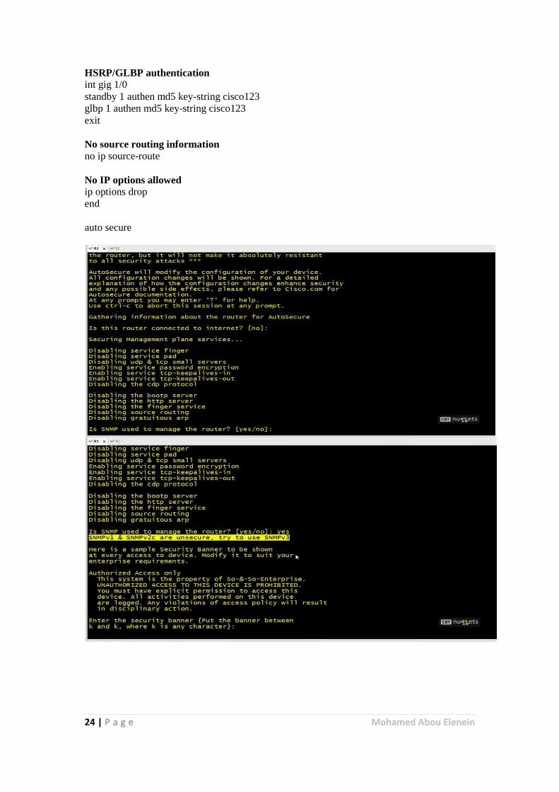
auto secure
25 | P a g e Mohamed Abou Elenein
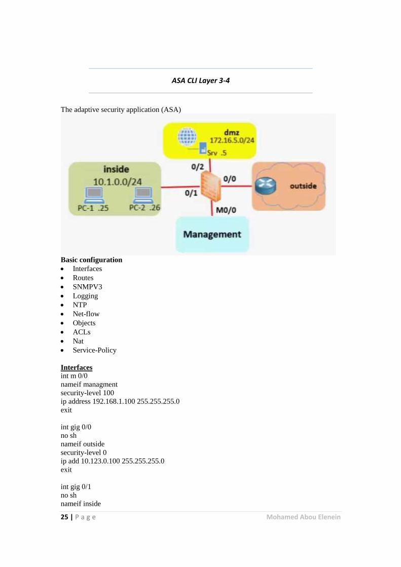
ASA CLI Layer 3-4
The adaptive security application (ASA)
Basic configuration
Interfaces
Routes
SNMPV3
Logging
NTP
Net-flow
Objects
ACLs
Nat
Service-Policy
Interfaces
int m 0/0
nameif managment
security-level 100
ip address 192.168.1.100 255.255.255.0
exit
int gig 0/0
no sh
nameif outside
security-level 0
ip add 10.123.0.100 255.255.255.0
exit
int gig 0/1
no sh
nameif inside
26 | P a g e Mohamed Abou Elenein
security-level 100
ip add 10.10.0.100 255.255.255.0
exit
http server enable
http 192.168.1.0 255.255.255.0 management
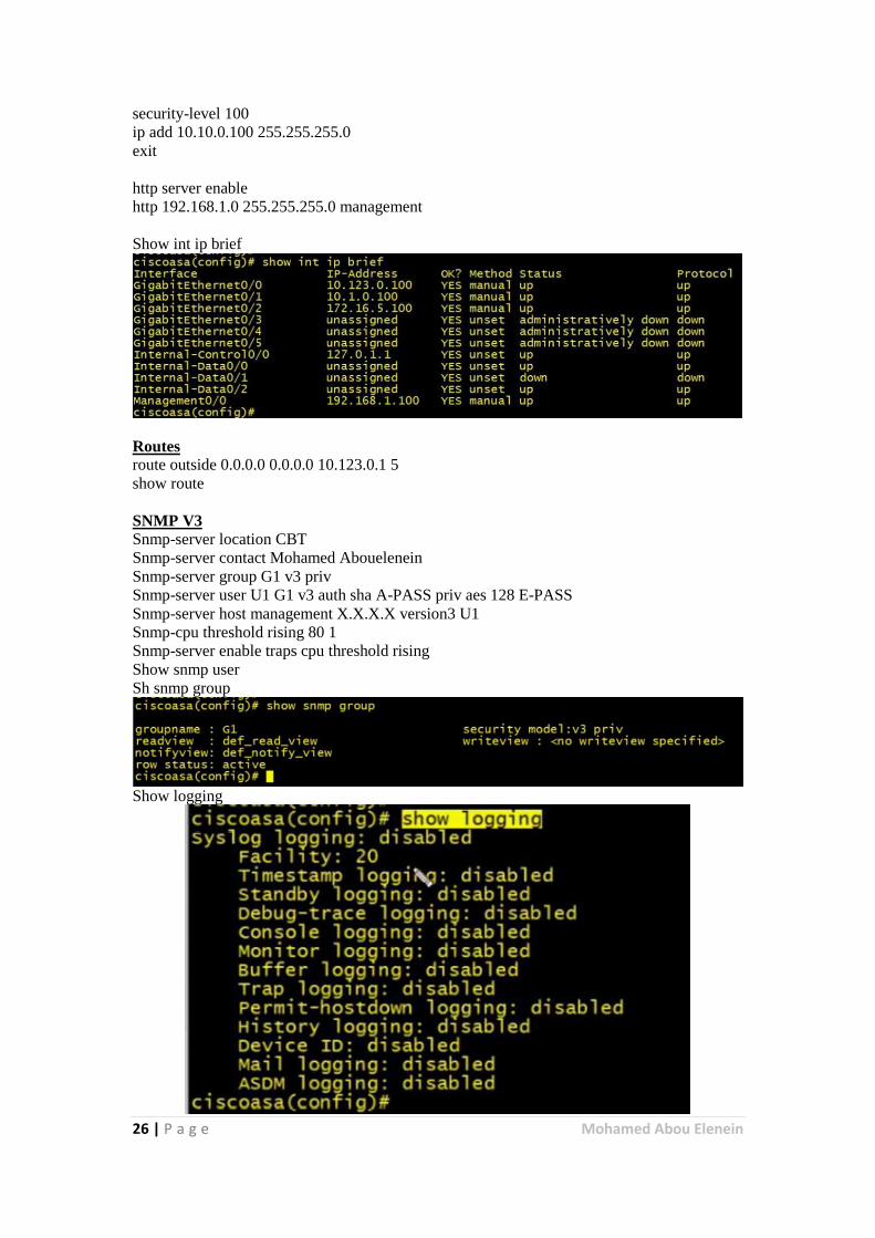
Show int ip brief
Routes
route outside 0.0.0.0 0.0.0.0 10.123.0.1 5
show route
SNMP V3
Snmp-server location CBT
Snmp-server contact Mohamed Abouelenein
Snmp-server group G1 v3 priv
Snmp-server user U1 G1 v3 auth sha A-PASS priv aes 128 E-PASS
Snmp-server host management X.X.X.X version3 U1
Snmp-cpu threshold rising 80 1
Snmp-server enable traps cpu threshold rising
Show snmp user
Sh snmp group
Show logging
27 | P a g e Mohamed Abou Elenein
Logging
Logging enable
Logging hot management X.X.X.X
Logging trap 5
Logging console 4
Logging buffered 6
Logging list OUR-EVENT-LIST message 101001-101003
Smtp-server X.X.X.X
Logging address [email protected]
Logging recipient-address [email protected] level information
Logging mail OUR-EVENT-LIST
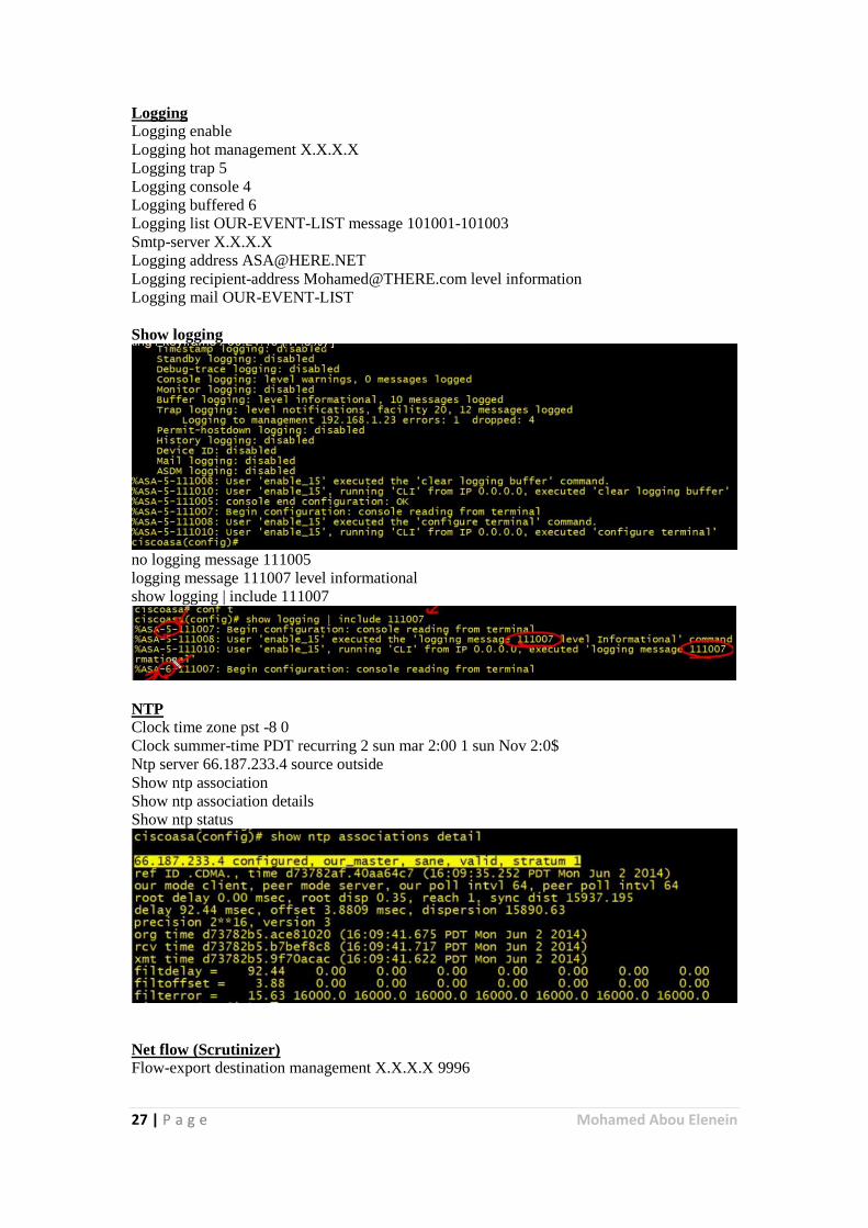
Show logging
no logging message 111005
logging message 111007 level informational
show logging | include 111007
NTP
Clock time zone pst -8 0
Clock summer-time PDT recurring 2 sun mar 2:00 1 sun Nov 2:0$
Ntp server 66.187.233.4 source outside
Show ntp association
Show ntp association details
Show ntp status
Net flow (Scrutinizer)
Flow-export destination management X.X.X.X 9996
28 | P a g e Mohamed Abou Elenein
Class-map GLOBAL-CLASS
Match any
Exit
Policy-map GLOBAL-POLICY
Class GLOBAL-CLASS
Flow-export event-type all destination X.X.X.X
Exit
Exit
Nat
Object network SRV-1
Host 172.16.5.5
Nat static 10.123.0.5 net-to-net
Exit
Object
Object network SRV-2
Host 172.16.5.6
exit
Object network SRV-3
Host 172.16.5.7
Exit
Object-group network DMZ-SERVER
Network-object object SRV-1
Network-object object SRV-2
Network-object object SRV-3
Object-group service WEB-SERVICES
Service-object tcp destination eq http
Service-object tcp destination eq https
Exit.
ACLS
Access-list OUTSIDE-ACCSES-IN permit object-group WEB-SERVICES
Access-group OUTSIDE-ACCSES-IN in interface outside
ASA CLI Layer 5-7
Class
Policy
Service-policy
APP on Nonstandard ports (:8123 ...etc.)
Reset any request from http ask for EXE inspection
Regex LOOKING-4-EXE ".+\.[Ee][Xx][Ee]"
29 | P a g e Mohamed Abou Elenein
Class-map type regex match-any REGEX-CLASS-MAP
Match regex LOOKING-4-EXE
Exit
Class-map type inspect http match-all HTTP-CLASS-MAP
Match request uri regex class REGEX-CLASS-MAP
Exit
Policy-map type inspect http HTTP-POLICY-MAP
Parameter
Protocol-violation action reset log
Exit
Class HTTP-CLASS-MAP
Reset log
Exit
Exit
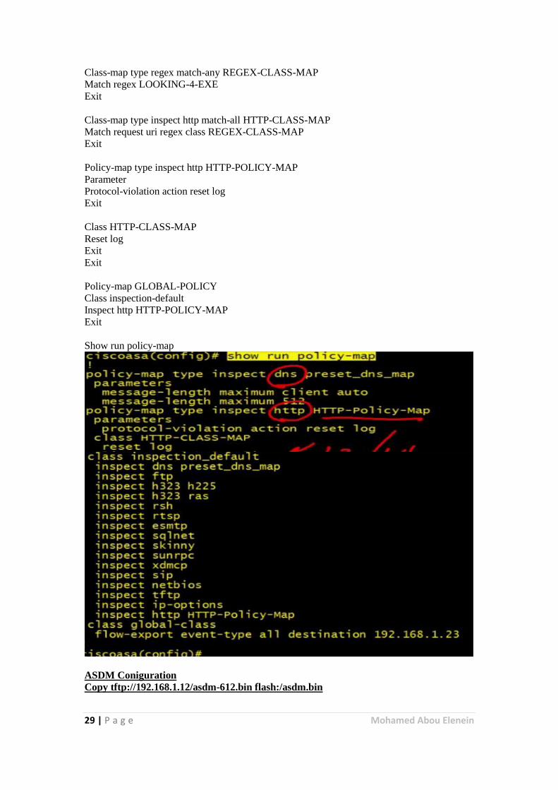
Policy-map GLOBAL-POLICY
Class inspection-default
Inspect http HTTP-POLICY-MAP
Exit
Show run policy-map
ASDM Coniguration
Copy tftp://192.168.1.12/asdm-612.bin flash:/asdm.bin
30 | P a g e Mohamed Abou Elenein
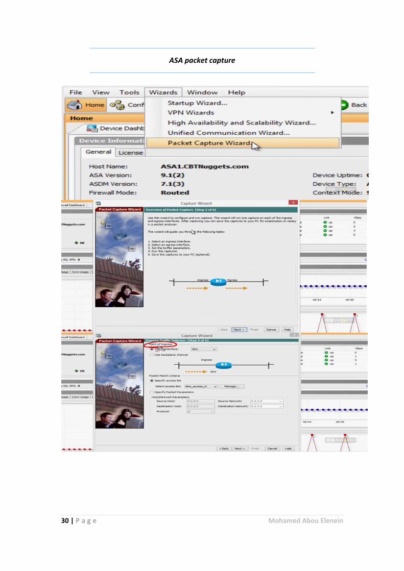
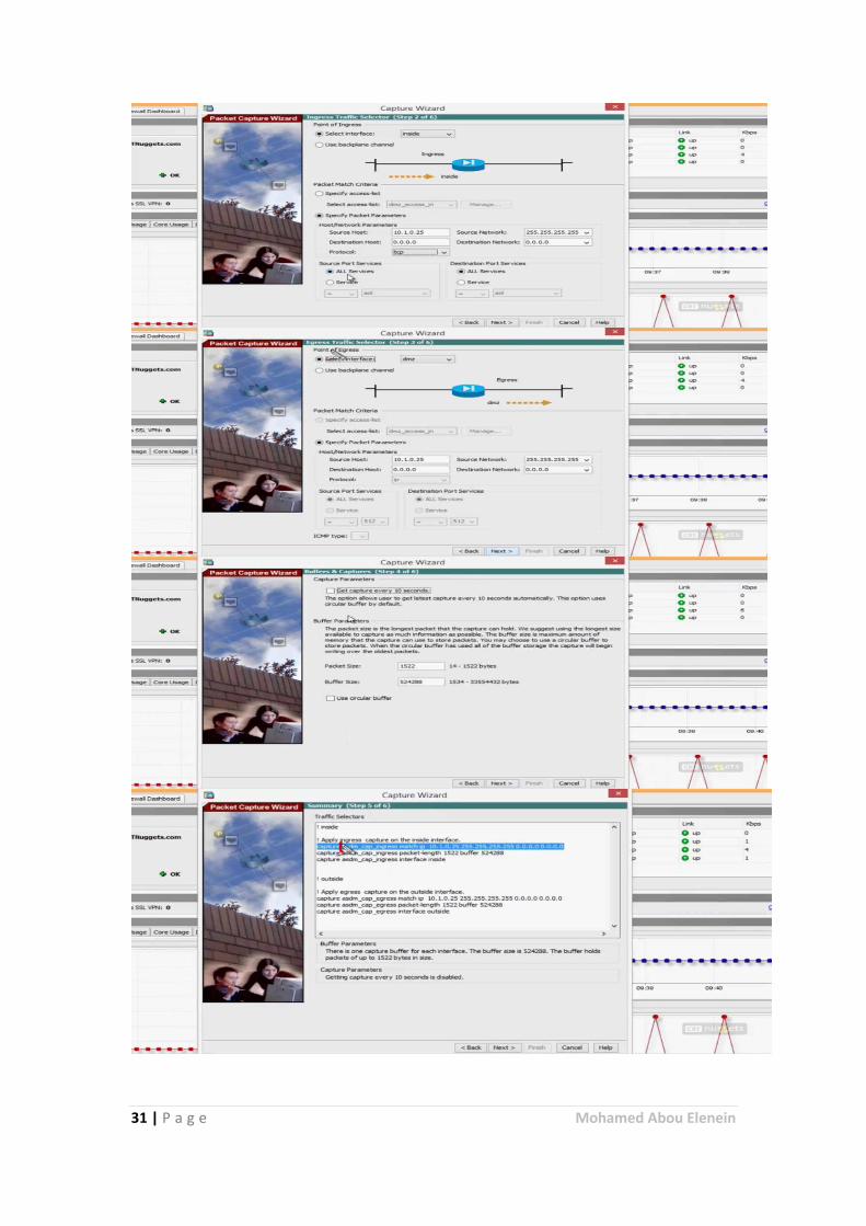
ASA packet capture
31 | P a g e Mohamed Abou Elenein
32 | P a g e Mohamed Abou Elenein
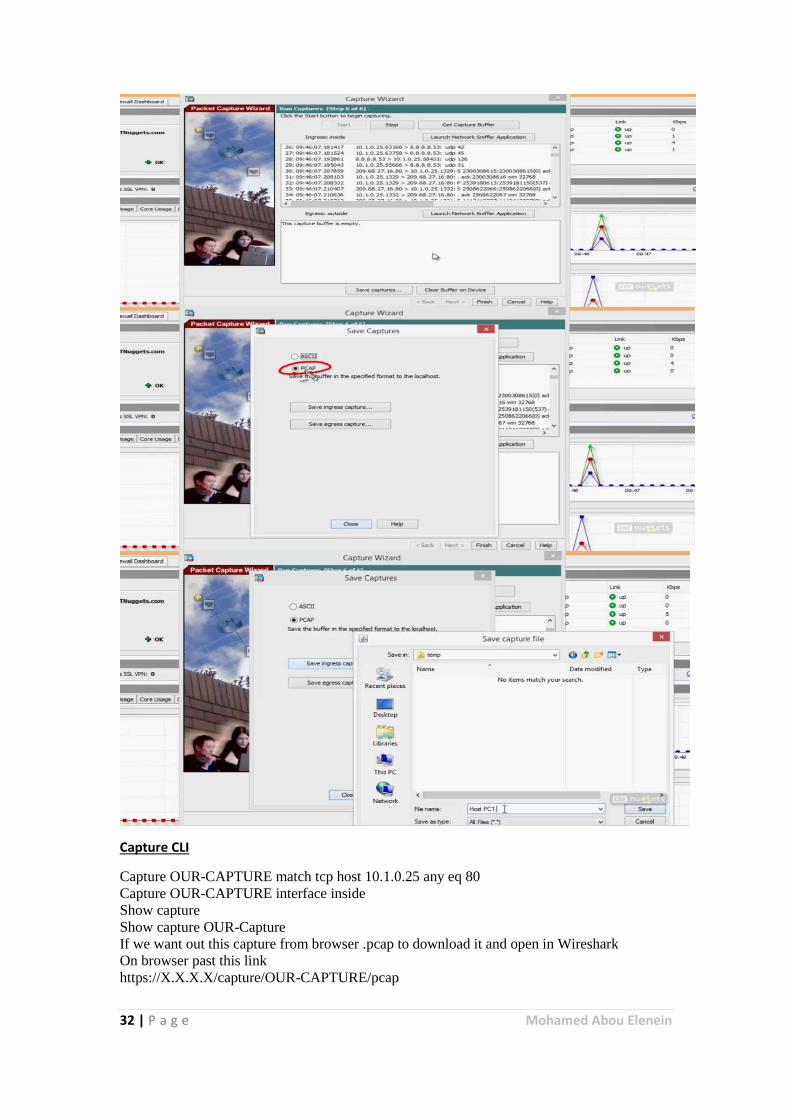
Capture CLI
Capture OUR-CAPTURE match tcp host 10.1.0.25 any eq 80
Capture OUR-CAPTURE interface inside
Show capture
Show capture OUR-Capture
If we want out this capture from browser .pcap to download it and open in Wireshark
On browser past this link
https://X.X.X.X/capture/OUR-CAPTURE/pcap
33 | P a g e Mohamed Abou Elenein
Botnet Filtering
A botnet is a collection of Internet-connected programs communicating with other similar
programs in order to perform tasks. This can be as mundane as keeping control of an Internet
Relay Chat (IRC) channel, or it could be used to send spam email or participate in distributed
denial-of-service attacks. The word botnet is a combination of the words robot and network.
Types of botnet
Legal botnets
The term botnet is widely used when several IRC bots have been linked and may possibly set
channel modes on other bots and users while keeping IRC channels free from unwanted users.
This is where the term is originally from, since the first illegal botnets were similar to legal
botnets. A common bot used to set up botnets on IRC is egg drop.
Illegal botnets
Botnets sometimes compromise computers whose security defenses have been breached and
control conceded to a third party. Each such compromised device, known as a "bot", is
created when a computer is penetrated by software from a malware (malicious software)
distribution. The controller of a botnet is able to direct the activities of these compromised
computers through communication channels formed by standards-based network protocols
such as IRC and Hypertext Transfer Protocol (HTTP).
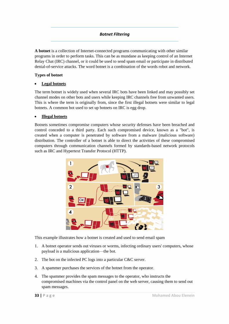
This example illustrates how a botnet is created and used to send email spam
1. A botnet operator sends out viruses or worms, infecting ordinary users' computers, whose
payload is a malicious application—the bot.
2. The bot on the infected PC logs into a particular C&C server.
3. A spammer purchases the services of the botnet from the operator.
4. The spammer provides the spam messages to the operator, who instructs the
compromised machines via the control panel on the web server, causing them to send out
spam messages.
34 | P a g e Mohamed Abou Elenein
Configuration at ASA
Enable DNS client/snooping
Edit botnet settings
Dynamic data
Black and white lists
Blocking Actions/levels
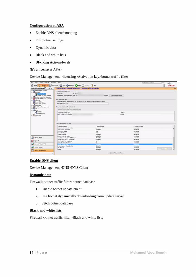
(It's a license at ASA):
Device Management >licensing>Activation key>botnet traffic filter
Enable DNS client
Device Management>DNS>DNS Client
Dynamic data
Firewall>botnet traffic filter>botnet database
1. Unable botnet update client
2. Use botnet dynamically downloading from update server
3. Fetch botnet database
Black and white lists
Firewall>botnet traffic filter>Black and white lists
35 | P a g e Mohamed Abou Elenein
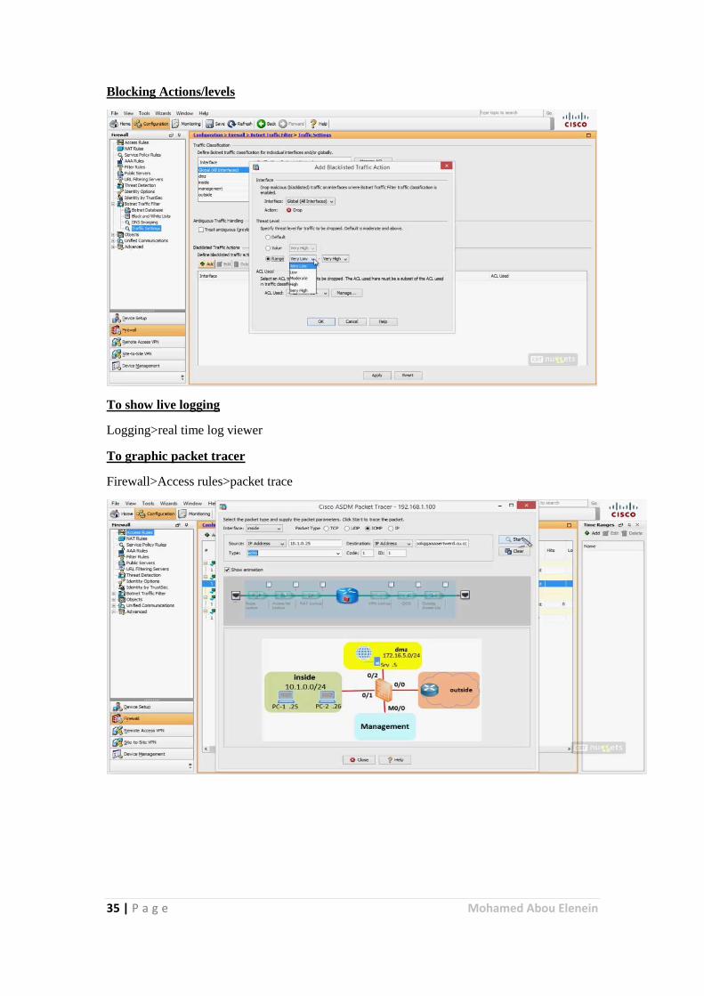
Blocking Actions/levels
To show live logging
Logging>real time log viewer
To graphic packet tracer
Firewall>Access rules>packet trace
36 | P a g e Mohamed Abou Elenein
Context Directory Agent Overview
Unlike traditional security mechanisms, Cisco’s security gateways such as ASA-CX, WSA,
ASA and the Cloud-based CWS service, provide security to networks based on the context of
the entity requiring access. While traditional network and content security gateways used to
rely on the entity’s IP Address only to determine if it should pass the security gateway or not,
today’s Cisco products allow to take into account much additional information, and make
decisions based on the complete context of the network entity, such as the user currently
using it, what operating system it uses, what location is it in, and so on. Security
administrators write policies using reference to this context, and when network traffic hits the
security gateway, it needs to check what is the context of the originating (and sometimes, also
the destined) IP Address.
Cisco Context Directory Agent (CDA) is a mechanism that maps IP Addresses to usernames
in order to allow security gateways to understand which user is using which IP Address in the
network, so those security gateways can now make decisions based on those users (or the
groups to which the users belong to).
CDA runs on a Cisco Linux machine; monitors in real time a collection of Active Directory
domain controller (DC) machines for authentication-related events that generally indicate user
logins; learns, analyzes, and caches mappings of IP Addresses and user identities in its
database; and makes the latest mappings available to its consumer devices.
Starting with patch 2, CDA can now receive information from Cisco Identity Services Engine
(ISE) and Cisco Secure Access Control Server (ACS) machines about 802.1x network logins,
in order to map users that do not directly login into Active Directory. CDA acts as a syslog
server, receiving syslog messages from ISE and ACS, and populates the mapping table using
network login information derived from ISE and ACS.
Consumer devices, such as the Cisco Adaptive Security Appliance (ASA) and the Cisco
IronPort Web Security Appliance (WSA), interact with the CDA using the RADIUS protocol
in order to obtain the latest set of IP-to-user-identity mappings, in any one of the following
ways:
On-Demand —CDA can respond to an on-demand query from the consumer device for
a specific mapping.
Full Download —CDA can respond to a request from the consumer device for the entire
set of mappings currently in its cache.
For both the on-demand and full-download methods, the request from the consumer device
can be specially tagged to indicate that it also includes a registration regarding any subsequent
updates.
For example, when a consumer device requests a basic on-demand query, CDA responds with
the specific mapping that might have been found in its cache, and does not send any further
updates about that mapping. On the other hand, if the on-demand query also includes a
registration, the initial response from CDA is the same as before and if, at a later point in
time, that specific mapping undergoes a change, then CDA proactively notifies the requesting
consumer device (as well as any other consumer devices that have registered for notification)
about the change in that specific mapping.
37 | P a g e Mohamed Abou Elenein
Similarly, when a consumer device requests a basic full download, CDA transfers a snapshot
of the session data containing all of the mappings currently found in its cache, and does not
send any further updates. On the other hand, if the request is to register for replication, then
the initial response from CDA is the same as before. At a later point in time, if the set of
mappings undergoes any sort of change (new mappings added or certain mappings changed
and so on), then CDA proactively notifies the requesting consumer device (as well as any
other consumer devices that have registered for replication) about these changes, relative to
the snapshot that was previously sent.
The IP-to-user-identity mappings that are discovered, maintained, and provided by CDA can
include not only IPv4 addresses, but also IPv6 addresses.
CDA can send logs to one or more syslog servers.
CDA continues to function if any of the Active Directory domain controllers or the consumer
devices have failed. It obtains information from other domain controllers. However, there is
no failover for CDA. CDA internally contains a “watchdog” functionality that continuously
monitors the Linux processes internal to it, automatically restarting them if it detects that they
have crashed. While there is no failover for CDA in itself, the solution as a whole does
support failover, controlled by the consumer devices, using their capability to configure a
primary and secondary CDA (similar to primary and secondary RADIUS server), and failover
to the secondary server in case the primary is unresponsive. It should be noted that primary
and secondary CDAs are completely unaware of each other, and do not exchange any state
information.
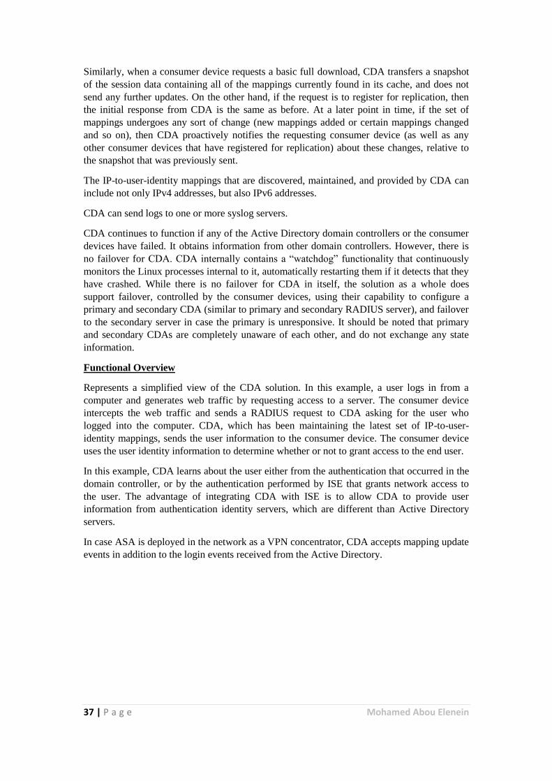
Functional Overview
Represents a simplified view of the CDA solution. In this example, a user logs in from a
computer and generates web traffic by requesting access to a server. The consumer device
intercepts the web traffic and sends a RADIUS request to CDA asking for the user who
logged into the computer. CDA, which has been maintaining the latest set of IP-to-user-
identity mappings, sends the user information to the consumer device. The consumer device
uses the user identity information to determine whether or not to grant access to the end user.
In this example, CDA learns about the user either from the authentication that occurred in the
domain controller, or by the authentication performed by ISE that grants network access to
the user. The advantage of integrating CDA with ISE is to allow CDA to provide user
information from authentication identity servers, which are different than Active Directory
servers.
In case ASA is deployed in the network as a VPN concentrator, CDA accepts mapping update
events in addition to the login events received from the Active Directory.
38 | P a g e Mohamed Abou Elenein
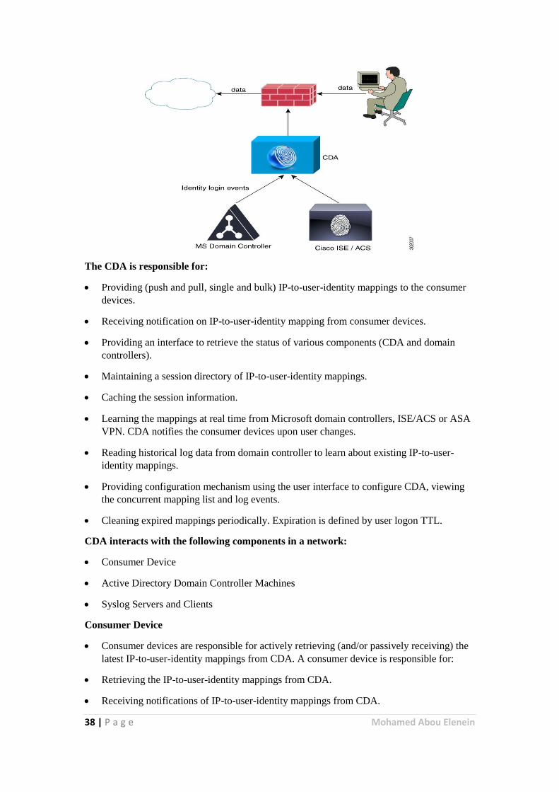
The CDA is responsible for:
Providing (push and pull, single and bulk) IP-to-user-identity mappings to the consumer
devices.
Receiving notification on IP-to-user-identity mapping from consumer devices.
Providing an interface to retrieve the status of various components (CDA and domain
controllers).
Maintaining a session directory of IP-to-user-identity mappings.
Caching the session information.
Learning the mappings at real time from Microsoft domain controllers, ISE/ACS or ASA
VPN. CDA notifies the consumer devices upon user changes.
Reading historical log data from domain controller to learn about existing IP-to-user-
identity mappings.
Providing configuration mechanism using the user interface to configure CDA, viewing
the concurrent mapping list and log events.
Cleaning expired mappings periodically. Expiration is defined by user logon TTL.
CDA interacts with the following components in a network:
Consumer Device
Active Directory Domain Controller Machines
Syslog Servers and Clients
Consumer Device
Consumer devices are responsible for actively retrieving (and/or passively receiving) the
latest IP-to-user-identity mappings from CDA. A consumer device is responsible for:
Retrieving the IP-to-user-identity mappings from CDA.
Receiving notifications of IP-to-user-identity mappings from CDA.
39 | P a g e Mohamed Abou Elenein
Enforcing identity based firewall policy.
Basic monitoring of the Active Directory connectivity via CDA.
Retrieving group information directly from the Active Directory.
Web-auth fallback for IPs that CDA did not map to identity.
Forwarding of new mappings revealed by consumer devices via the web-auth to CDA.
Forwarding IP-to-user-identity mapping for VPN sessions.
Running NetBIOS probing and forwarding disconnect notification to CDA.
These updates are sent as RADIUS Accounting-Request messages.
CDA Performance and Scalability
CDA can support up to 80 domain controller machines, and can internally cache up to 64,000
IP-to-user-identity mappings. It supports up to 100 Identity consumer devices. CDA processes
1000 IP-to-user-identity mappings per second (input and output).
CDA is tested to support three Syslog clients (when it acts as a syslog server), twenty
administrators, and five concurrent admin user interface sessions.
IPS& IDS
IPS (Intrusion Prevention System) and IDS (Intrusion Detection Systems)
IPS and IDS systems look for intrusions and symptoms within traffic. IPS/IDS systems would
monitor for unusual behavior, abnormal traffic, malicious coding and anything that would
look like an intrusion by a hacker being attempted.
IPS (Intrusion Prevention System) systems are deployed inline and actually take action by
blocking the attack, as well as logging the attack and adding the source IP address to the
block list for a limited amount of time; or even permanently blocking the address depending
on the defined settings. Hackers take part in lots of port scans and address scans, intending to
find loop holes within organizations. IPS systems would recognize these types of scans and
take actions such as block, drop, quarantine and log traffic. However this is the basic
functionality of IPS. IPS systems have many advanced capabilities in sensing and stopping
such attacks.
IDS vs. IPS
IDS (Intrusion Detection System) systems only detect an intrusion, log the attack and send an
alert to the administrator. IDS systems do not slow networks down like IPS as they are not
inline.
You may wonder why a company would purchase an IDS over an IPS? Surely a company
would want a system to take action and block such attacks rather than letting it pass and only
logging and alerting the administer. Well there’s a few reasons; however there are two
primary reasons which stand out. IDS systems if not fine-tuned, just like IPS will also
produce false positives. However it would be very annoying to have an IPS system producing
40 | P a g e Mohamed Abou Elenein
false positives as legitimate network traffic will be blocked as where an IDS will just send
alerts and log the false attack. The 2nd reason is some administrators and managers do not
want a system to take over and make decisions on their behalf; they would rather receive an
alert and look into the problem and take action themselves.
However that said today you will find solutions with both capabilities of IDS and IPS built in.
IDS can be used initially to see how the system behaves without actually blocking anything.
Then once fine-tuned IPS can be turned on and the system can be deployed inline to provide
full protection.
IPS and IDS vs Firewalls
Not having an IPS system result in attacks going unnoticed. Don’t forget a firewall does the
filtering, blocking and allowing of addresses, ports, service, but also allows some of these
through the network as well. However this means that the access allowed is just let through,
and firewalls have no clever way of telling whether that traffic is legit and normal. This is
where the IPS and IDS systems come into play.
So where firewalls block and allow traffic through, IDS/IPS detect and look at that traffic in
close detail to see if it is an attack. IDS/IPS systems are made up of sensors, analysers and
GUI’s in order to do their specialized job.
The Job of an IPS\IDS system
Let's take a closer at an IPS/IDS (also known as IPD systems).
Most common attack types that IPS and IDS systems are used for are;
Policy Violations - Rules, protocols and packet designs that are violated. An example
would be an IP packet that are incorrect in length.
Exploits - Attempts to exploit a vulnerability of a system, application or protocol. An
example would be a buffer overflow attacks.
Reconnaissance - Is a detection method that is used to gain information about system or
network such as using port scanners to see what ports are open.
DOS\DDOS - This is when an attack attempts to bring down your system by sending a
vast amount of requests to it such as SYN flood attacks.
IPS Techniques to defend against Attacks
Intrusion prevention sensors look at header and data portions of the traffic looking for
suspicious traffic that indicate malicious activity.
IPS/IDS solution have the ability to detect threats using a database of signatures, using
anomaly detection techniques looking for abnormal behavior within protocols and can also
use or integrate with anti-virus for malware detection. Anomaly detection systems target
traffic that isn't necessarily bad but used with bad intentions such as lots of traffic to
overwhelm a system. TCP Sync Flood attack is an example.
IPS have the ability to take actions on defined policies such as blocking a connection,
providing alerts, logging the event, quarantining the host or a combination of these. Policies
define the rules that specify what should be detected and type of response required. Policies
will include both signature based rules and anomaly detection rules for learning typical
41 | P a g e Mohamed Abou Elenein
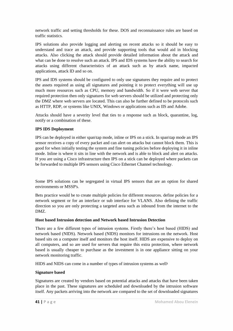
network traffic and setting thresholds for these. DOS and reconnaissance rules are based on
traffic statistics.
IPS solutions also provide logging and alerting on recent attacks so it should be easy to
understand and trace an attack, and provide supporting tools that would aid in blocking
attacks. Also clicking the attack should provide detailed information about the attack and
what can be done to resolve such an attack. IPS and IDS systems have the ability to search for
attacks using different characteristics of an attack such as by attack name, impacted
applications, attack ID and so on.
IPS and IDS systems should be configured to only use signatures they require and to protect
the assets required as using all signatures and pointing it to protect everything will use up
much more resources such as CPU, memory and bandwidth. So if it were web server that
required protection then only signatures for web servers should be utilized and protecting only
the DMZ where web servers are located. This can also be further defined to be protocols such
as HTTP, RDP, or systems like UNIX, Windows or applications such as IIS and Adobe.
Attacks should have a severity level that ties to a response such as block, quarantine, log,
notify or a combination of these.
IPS IDS Deployment
IPS can be deployed in either span\tap mode, inline or IPS on a stick. In span\tap mode an IPS
sensor receives a copy of every packet and can alert on attacks but cannot block them. This is
good for when initially testing the system and fine tuning policies before deploying it in inline
mode. Inline is where it sits in line with the network and is able to block and alert on attacks.
If you are using a Cisco infrastructure then IPS on a stick can be deployed where packets can
be forwarded to multiple IPS sensors using Cisco Ethernet Channel technology.
Some IPS solutions can be segregated in virtual IPS sensors that are an option for shared
environments or MSSP's.
Bets practice would be to create multiple policies for different resources. define policies for a
network segment or for an interface or sub interface for VLANS. Also defining the traffic
direction so you are only protecting a targeted area such as inbound from the internet to the
DMZ.
Host based Intrusion detection and Network based Intrusion Detection
There are a few different types of intrusion systems. Firstly there’s host based (HIDS) and
network based (NIDS). Network based (NIDS) monitors for intrusions on the network. Host
based sits on a computer itself and monitors the host itself. HIDS are expensive to deploy on
all computers, and so are used for servers that require this extra protection, where network
based is usually cheaper to purchase as the investment is in one appliance sitting on your
network monitoring traffic.
HIDS and NIDS can come in a number of types of intrusion systems as well;
Signature based
Signatures are created by vendors based on potential attacks and attacks that have been taken
place in the past. These signatures are scheduled and downloaded by the intrusion software
itself. Any packets arriving into the network are compared to the set of downloaded signatures
42 | P a g e Mohamed Abou Elenein
comparing these for any attacks. Signature based systems are the most common. Most UTM
appliances consist of signature based intrusion prevention/detection systems. The only
downfall to these systems is that they can not detect new attacks, as they only compare attacks
to the signatures their system currently holds.
Anomaly based
In anomaly based, the system would first need to learn the NORMAL behavior, traffic or
protocol set of the network. When the system has learnt the normal state of a network and the
types of packets and throughput it handles on a daily basis, taking into account peak times
such as lunch time for example for web browsing, then it can be put into action. Now when
traffic is detected that is out of the normal state of the network, the anomaly based detection
system would take action.
The good thing about this type of system is that it can detect new attacks; it does not need to
rely on signatures. The bad thing is if you do not spend time fine stunning the system and
maintaining it, it will usually produce many false positives (Stop normal traffic). Also some
clever hackers try and emulating their attacks as normal traffic, however this is usually
difficult to do from a hacking perspective, but if they get it right, it may fool the ADS system
as normal and legitimate traffic.
Rule based
Rule based systems are more advanced and cleverly built systems. A knowledge base
programmed as rules will decide the output alongside an inference engine. If the defined rules
for example all match, a certain assumption can be determined in which an action may take
place. This assumption is the power of the inference engine. The inference engine can assume
an attack may be occurring because of so many factors; this is unique and is very much
behaving like the human mind. In normal computing assumptions cannot be made, its either
yes or no, but the inference engine adds a different level of thinking; it also adds the
“Probably” to the list, like humans. If it rains and is warm, we can assume it may thunder. If
more traffic was leaving the company than usual, as well as coming from a certain server, the
inference engine may assume, the server could be compromised by a hacker.
Many IDS/IPS solutions have combined both signature and anomaly based detection system.
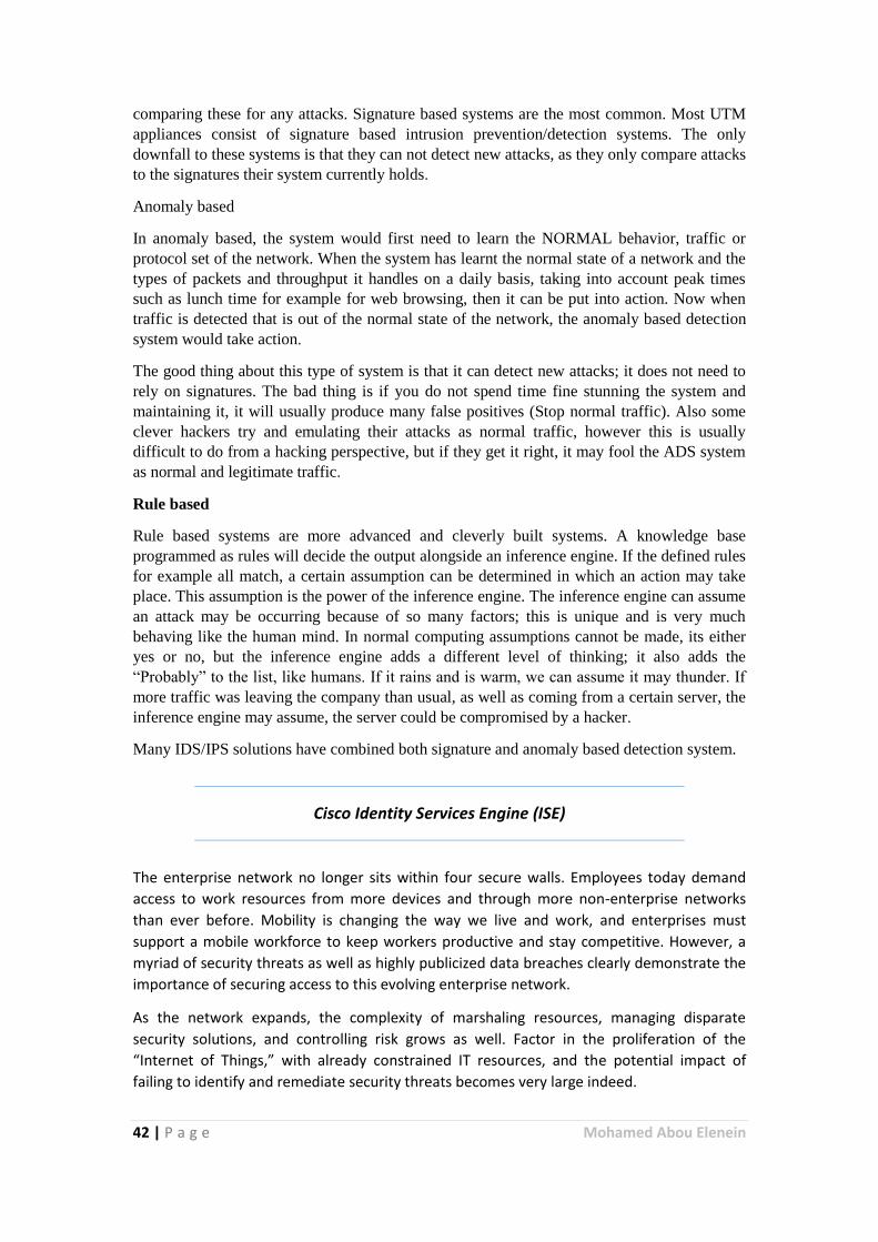
Cisco Identity Services Engine (ISE)
The enterprise network no longer sits within four secure walls. Employees today demand
access to work resources from more devices and through more non-enterprise networks
than ever before. Mobility is changing the way we live and work, and enterprises must
support a mobile workforce to keep workers productive and stay competitive. However, a
myriad of security threats as well as highly publicized data breaches clearly demonstrate the
importance of securing access to this evolving enterprise network.
As the network expands, the complexity of marshaling resources, managing disparate
security solutions, and controlling risk grows as well. Factor in the proliferation of the
“Internet of Things,” with already constrained IT resources, and the potential impact of
failing to identify and remediate security threats becomes very large indeed.
43 | P a g e Mohamed Abou Elenein
A different approach is required for both the management and security of the evolving
mobile enterprise. It’s called the Cisco Identity Services Engine (ISE).
Narrow Your Exposure and Reduce Your Risk It all starts with getting ahead of threats by
using visibility and control – visibility into the users and devices accessing your network and
the control to help ensure that only the right people from the right devices get the right
access to the enterprise services they need.
This is where Cisco ISE can help. Cisco ISE is the market-leading security policy management
platform that unifies and automates access control to proactively enforce role-based access
to enterprise networks and resources, regardless of how a user chooses to connect – by
wired or wireless networks or VPN.
Traditionally, security solutions, focused on preventing compromised devices or users from
gaining access to network resources, have generally been too complex to configure and
deploy, requiring weeks of setup and large investments in resources.
The latest release of Cisco ISE is different. With out-of-the-box configured workflows, Cisco
ISE accelerates the deployment of guest access and 802.1X RADIUS authentication.
Enterprises can choose to expand their deployments and use Cisco ISE to create access
policies using Cisco Trust Sec® Security Group Tags (SGTs). These define access based on
simple “plain English” rules and use built-in technology within the Cisco infrastructure to
enforce policy across the network.
Additionally, Cisco ISE uses Cisco Platform Exchange Grid (pxGrid) technology to share rich
contextual data with integrated partner ecosystem solutions. This technology accelerates
their capabilities to identify, mitigate, and remediate security threats across your extended
network. Overall, secure access control is centralized and simplified to securely deliver vital
business services, enhance infrastructure security, enforce compliance and streamline
service operations.
Providing control with context makes Cisco ISE a key component in the Cisco security
portfolio as well as the Cisco Open Network Environment (ONE) architecture, which
promotes the easier connection of people, processes, data, and things with greater
intelligence and efficiency. Cisco ISE is one of the three pillars of the Cisco Unified Access
solution, which lets you work your way with “One Policy, One Management, and One
Network.” Through its ecosystem integrations with leading security information and event
management and threat defense (SIEM/TD) solutions and its secure access policy
capabilities, Cisco ISE delivers the visibility, context, and dynamic control needed by
enterprises to effectively implement security that targets the entire attack continuum –
managing network access before an attack while improving detection, mitigation, and
remediation during and after an attack as well
Benefits
Centralize and unify highly secure access control to provide a consistent network access
policy for end users whether they connect through a wired or wireless network or VPN.
Gain greater visibility and more accurate device identification with Cisco ISE’s superior
device profiling and device profile feed service, which together reduce the number of
44 | P a g e Mohamed Abou Elenein
unknown endpoints and potential threats on your network by 74 percent, on average,
based on Cisco engagements.
Simplify guest experiences for easier guest onboarding and administration through fully
customizable branded mobile and desktop guest portals, created in minutes with
dynamic visual workflows that let you easily manage every aspect of guest access.
Accelerate BYOD and enterprise mobility with easy out-of-the-box setup, selfservice
device onboarding and management, internal device certificate management, and
integrated enterprise mobility management (EMM) partner software.
Deploy logical network segmentation based on business rules by using Cisco TrustSec
technology to create a role-based access policy. This dynamically segments access
without the complexity of multiple VLANs or the need to change the network
architecture.
Share deep contextual data with third-party partner network and security solutions to
improve their overall efficacy as well as accelerate the identification, mitigation, and
remediation of network threats.
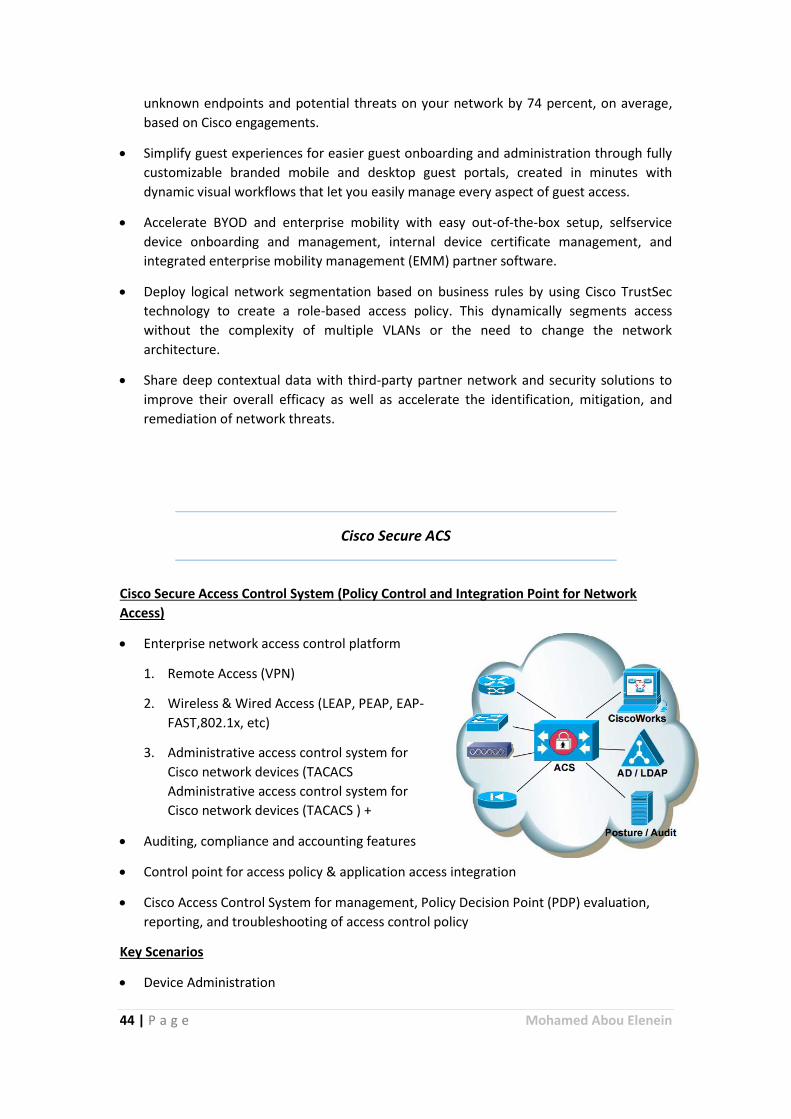
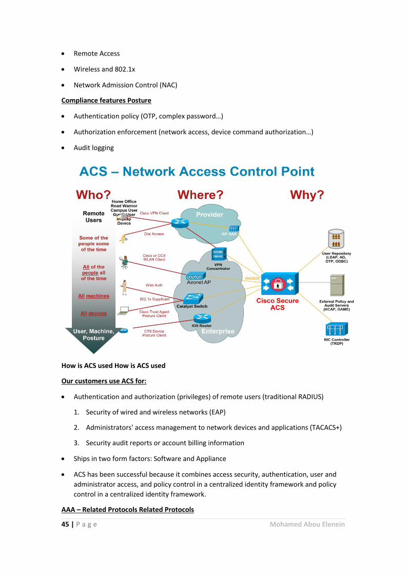
Cisco Secure ACS
Cisco Secure Access Control System (Policy Control and Integration Point for Network
Access)
Enterprise network access control platform
1. Remote Access (VPN)
2. Wireless & Wired Access (LEAP, PEAP, EAP-
FAST,802.1x, etc)
3. Administrative access control system for
Cisco network devices (TACACS
Administrative access control system for
Cisco network devices (TACACS ) +
Auditing, compliance and accounting features
Control point for access policy & application access integration
Cisco Access Control System for management, Policy Decision Point (PDP) evaluation,
reporting, and troubleshooting of access control policy
Key Scenarios
Device Administration
45 | P a g e Mohamed Abou Elenein
Remote Access
Wireless and 802.1x
Network Admission Control (NAC)
Compliance features Posture
Authentication policy (OTP, complex password…)
Authorization enforcement (network access, device command authorization…)
Audit logging
How is ACS used How is ACS used
Our customers use ACS for:
Authentication and authorization (privileges) of remote users (traditional RADIUS)
1. Security of wired and wireless networks (EAP)
2. Administrators' access management to network devices and applications (TACACS+)
3. Security audit reports or account billing information
Ships in two form factors: Software and Appliance
ACS has been successful because it combines access security, authentication, user and
administrator access, and policy control in a centralized identity framework and policy
control in a centralized identity framework.
AAA – Related Protocols Related Protocols
46 | P a g e Mohamed Abou Elenein
RADIUS – Remote Authentication Dial In User Service
TACACS+ - Terminal Access Controller Access Control System
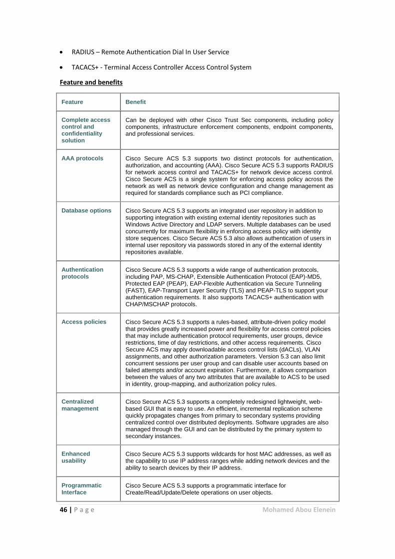
Feature and benefits
Feature Benefit
Complete access control and confidentiality solution
Can be deployed with other Cisco Trust Sec components, including policy components, infrastructure enforcement components, endpoint components, and professional services.
AAA protocols Cisco Secure ACS 5.3 supports two distinct protocols for authentication, authorization, and accounting (AAA). Cisco Secure ACS 5.3 supports RADIUS for network access control and TACACS+ for network device access control. Cisco Secure ACS is a single system for enforcing access policy across the network as well as network device configuration and change management as required for standards compliance such as PCI compliance.
Database options Cisco Secure ACS 5.3 supports an integrated user repository in addition to supporting integration with existing external identity repositories such as Windows Active Directory and LDAP servers. Multiple databases can be used concurrently for maximum flexibility in enforcing access policy with identity store sequences. Cisco Secure ACS 5.3 also allows authentication of users in internal user repository via passwords stored in any of the external identity repositories available.
Authentication protocols
Cisco Secure ACS 5.3 supports a wide range of authentication protocols, including PAP, MS-CHAP, Extensible Authentication Protocol (EAP)-MD5, Protected EAP (PEAP), EAP-Flexible Authentication via Secure Tunneling (FAST), EAP-Transport Layer Security (TLS) and PEAP-TLS to support your authentication requirements. It also supports TACACS+ authentication with CHAP/MSCHAP protocols.
Access policies Cisco Secure ACS 5.3 supports a rules-based, attribute-driven policy model that provides greatly increased power and flexibility for access control policies that may include authentication protocol requirements, user groups, device restrictions, time of day restrictions, and other access requirements. Cisco Secure ACS may apply downloadable access control lists (dACLs), VLAN assignments, and other authorization parameters. Version 5.3 can also limit concurrent sessions per user group and can disable user accounts based on failed attempts and/or account expiration. Furthermore, it allows comparison between the values of any two attributes that are available to ACS to be used in identity, group-mapping, and authorization policy rules.
Centralized management
Cisco Secure ACS 5.3 supports a completely redesigned lightweight, web-based GUI that is easy to use. An efficient, incremental replication scheme quickly propagates changes from primary to secondary systems providing centralized control over distributed deployments. Software upgrades are also managed through the GUI and can be distributed by the primary system to secondary instances.
Enhanced usability
Cisco Secure ACS 5.3 supports wildcards for host MAC addresses, as well as the capability to use IP address ranges while adding network devices and the ability to search devices by their IP address.
Programmatic Interface
Cisco Secure ACS 5.3 supports a programmatic interface for Create/Read/Update/Delete operations on user objects.
47 | P a g e Mohamed Abou Elenein
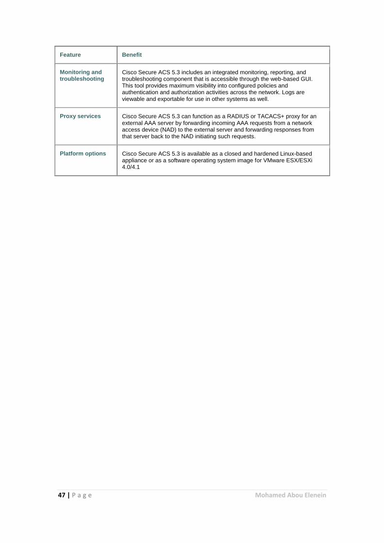
Feature Benefit
Monitoring and troubleshooting
Cisco Secure ACS 5.3 includes an integrated monitoring, reporting, and troubleshooting component that is accessible through the web-based GUI. This tool provides maximum visibility into configured policies and authentication and authorization activities across the network. Logs are viewable and exportable for use in other systems as well.
Proxy services Cisco Secure ACS 5.3 can function as a RADIUS or TACACS+ proxy for an external AAA server by forwarding incoming AAA requests from a network access device (NAD) to the external server and forwarding responses from that server back to the NAD initiating such requests.
Platform options Cisco Secure ACS 5.3 is available as a closed and hardened Linux-based appliance or as a software operating system image for VMware ESX/ESXi 4.0/4.1

48 | P a g e Mohamed Abou Elenein
References
Cisco web site https://cisco.com
CBT Nuggets videos "SENSS course"
Wikipedia website https://www.wikipedia.org
Others videos and stander documentations
Recommended