1
2
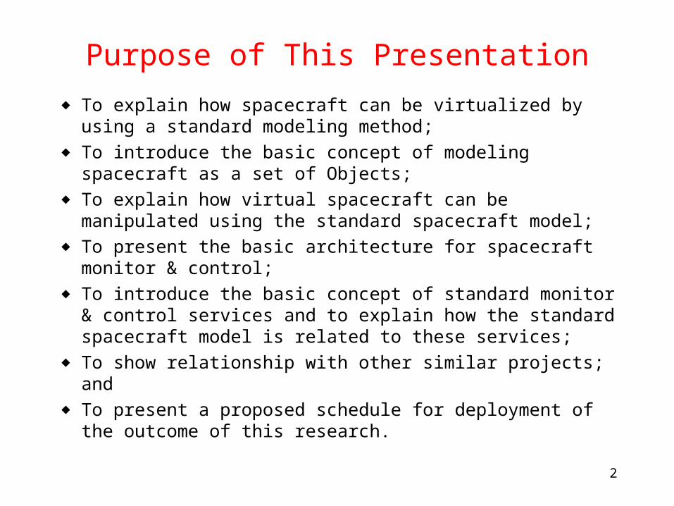
Purpose of This Presentation
◆ To explain how spacecraft can be virtualized by using a standard modeling method;
◆ To introduce the basic concept of modeling spacecraft as a set of Objects;
◆ To explain how virtual spacecraft can be manipulated using the standard spacecraft model;
◆ To present the basic architecture for spacecraft monitor & control;
◆ To introduce the basic concept of standard monitor & control services and to explain how the standard spacecraft model is related to these services;
◆ To show relationship with other similar projects; and◆ To present a proposed schedule for deployment of the outcome
of this research.
3
What is Virtualization of Spacecraft?
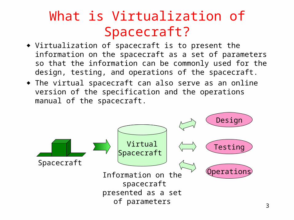
◆ Virtualization of spacecraft is to present the information on the spacecraft as a set of parameters so that the information can be commonly used for the design, testing, and operations of the spacecraft.
◆ The virtual spacecraft can also serve as an online version of the specification and the operations manual of the spacecraft.
VirtualSpacecraft
Spacecraft
Information on the spacecraft presented as
a set of parameters
Design
Operations
Testing
4
Standard Method for Virtualizing Spacecraft
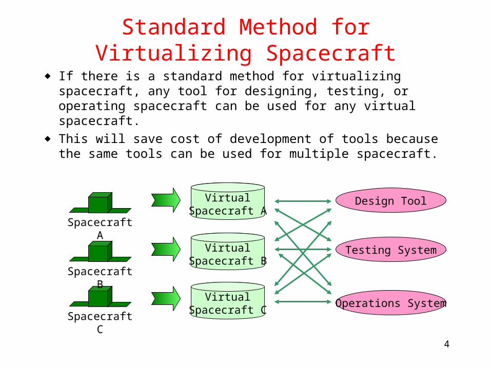
◆ If there is a standard method for virtualizing spacecraft, any tool for designing, testing, or operating spacecraft can be used for any virtual spacecraft.
◆ This will save cost of development of tools because the same tools can be used for multiple spacecraft.
VirtualSpacecraft A
Spacecraft B
Spacecraft A
Spacecraft C
Design Tool
Operations System
Testing System
VirtualSpacecraft C
VirtualSpacecraft B
5
A Standard Model for Virtualizing Spacecraft
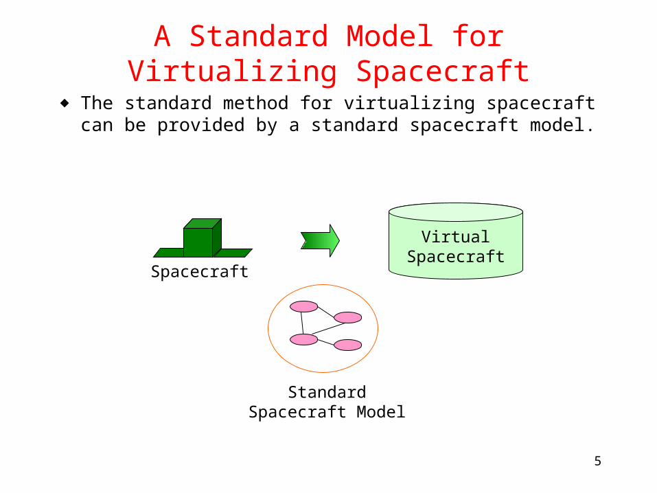
◆ The standard method for virtualizing spacecraft can be provided by a standard spacecraft model.
Spacecraft
Standard Spacecraft Model
VirtualSpacecraft
6
Then, What is a Standard Spacecraft Model?
◆ A standard spacecraft model provides a common framework for describing the characteristics and internal organization of spacecraft.
◆ The model specifies a standard set of elements (or objects), relationships between elements, attributes of elements, and attributes of relationships.
◆ Note: In the first stage of this project, only the functional aspect (i.e., the functions performed by spacecraft) and informational aspect (i.e., the information exchanged with and within spacecraft) will be modeled. Other aspects (structural, thermal, etc.) will be treated at a later stage of this project by extending the method described here.
7
Functional Model (or Functional View)
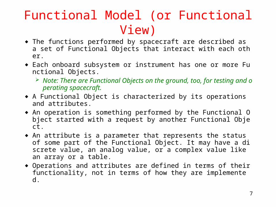
◆ The functions performed by spacecraft are described as a set of Functional Objects that interact with each other.
◆ Each onboard subsystem or instrument has one or more Functional Objects. Note: There are Functional Objects on the ground, too, for te
sting and operating spacecraft.◆ A Functional Object is characterized by its operations and attrib
utes.◆ An operation is something performed by the Functional Object s
tarted with a request by another Functional Object.◆ An attribute is a parameter that represents the status of some p
art of the Functional Object. It may have a discrete value, an analog value, or a complex value like an array or a table.
◆ Operations and attributes are defined in terms of their functionality, not in terms of how they are implemented.
8
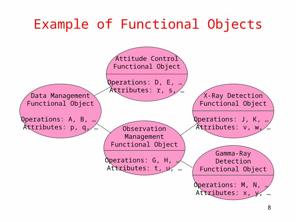
Example of Functional Objects
Gamma-RayDetection
Functional Object
Operations: M, N, … Attributes: x, y, …
ObservationManagement
Functional Object
Operations: G, H, … Attributes: t, u, …
X-Ray DetectionFunctional Object
Operations: J, K, … Attributes: v, w, …
Data ManagementFunctional Object
Operations: A, B, … Attributes: p, q, …
Attitude ControlFunctional Object
Operations: D, E, … Attributes: r, s, …
9
Types of Attributes of Functional Objects
◆ Some attributes are writable (e.g., on/off of switches and modes of operations). The value of writable attributes can be set by requests from
other Functional Objects. The value of writable attributes may change by some interna
l activities without receiving requests.◆ Some attributes are non-writable (e.g., readings of sensors).
The value of non-writable attributes cannot be changed by other Functional Objects.
10
Behavior of Functional Objects
◆ The behavior of Functional Objects can be described as rules on how attributes change or how they are interrelated with each other.
◆ The value of some discrete attributes may only change according to some rule (e.g., Off to Standby to On, but not directly Off to On). Such rules can be specified by state transition diagrams (or t
ables and how to specify state transition rules should be part of the standard spacecraft model.
◆ There may be constraints on the values of a group of attributes. Such constraints can be specified with a formal language an
d how to specify constraints should be part of the standard spacecraft model.
11
Informational Model (or Information View)
◆ The information exchanged between Functional Objects is described as a set of Information Objects.
◆ An Information Object is characterized by its semantics (what it means) and syntax (how it is realized or encoded).
◆ The semantics of Information Objects can be specified using the Functional View to some extent. For an example, see slides on Monitor and Control Services.
◆ An Information Object may be realized as a physical signal, a word or byte (i.e., a short string of bits), a data unit like a packet (i.e., an organized string of bits), or a file (i.e., a large amount of bits).
12
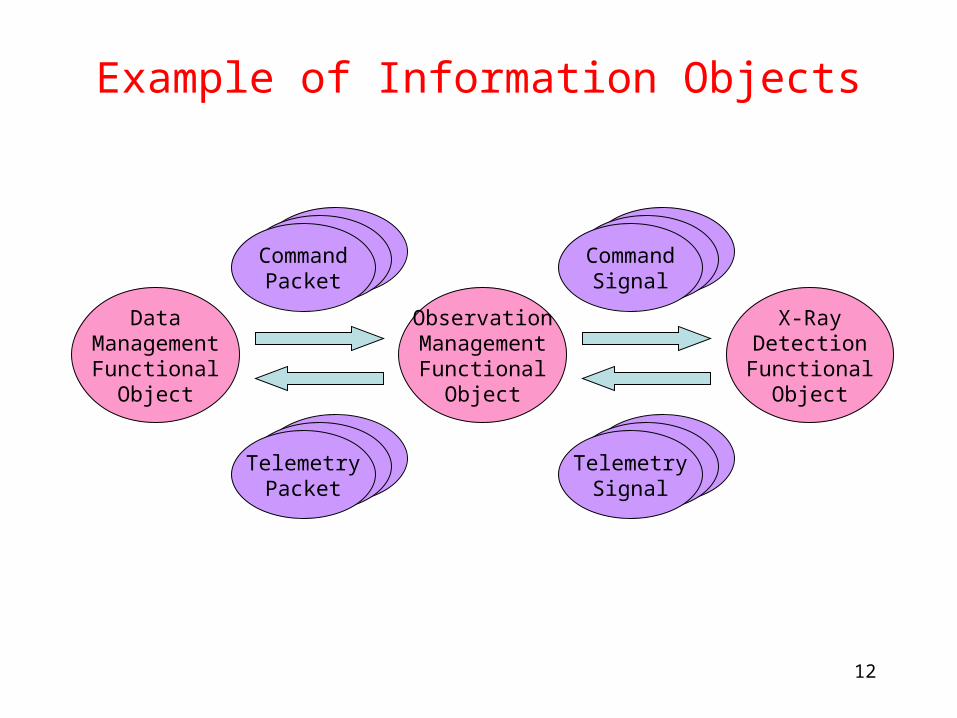
Example of Information Objects
ObservationManagement
FunctionalObject
CommandPacket
TelemetryPacket
DataManagement
FunctionalObject
X-RayDetectionFunctional
Object
CommandSignal
TelemetrySignal
13
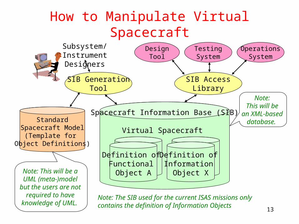
How to Manipulate Virtual Spacecraft
Spacecraft Information Base (SIB)
Virtual Spacecraft
Definition of Functional Object A
Definition of Information
Object X
SIB AccessLibrary
StandardSpacecraft Model
(Template for Object Definitions)
Subsystem/Instrument Designers
DesignTool
OperationsSystem
TestingSystem
SIB GenerationTool
Note: The SIB used for the current ISAS missions only contains the definition of Information Objects
Note: This will be a UML (meta-)model
but the users are not required to have
knowledge of UML.
Note: This will be
an XML-based database.
14
Interactions Between Functional Objects
◆ Interactions between Functional Objects can be classified into the following types: Synchronization between Functional Objects (such as
synchronization of the internal clocks of different Functional Objects),
Monitor and Control (see next slides), and Bulk data (such as memory upload/download and transfer of
observed data).◆ There may be interactions that have characteristics of two types
(for example, upload of a sequence of control requests).
15
Monitor and Control Interactions
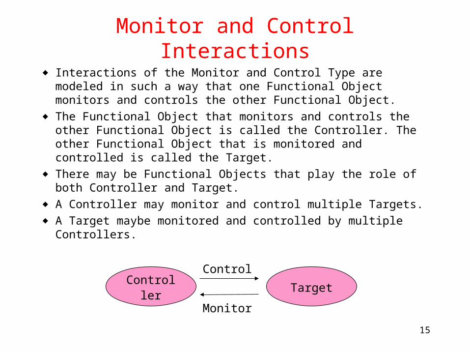
◆ Interactions of the Monitor and Control Type are modeled in such a way that one Functional Object monitors and controls the other Functional Object.
◆ The Functional Object that monitors and controls the other Functional Object is called the Controller. The other Functional Object that is monitored and controlled is called the Target.
◆ There may be Functional Objects that play the role of both Controller and Target.
◆ A Controller may monitor and control multiple Targets.◆ A Target maybe monitored and controlled by multiple
Controllers.
Controller
Control
Monitor
Target
16
Interactions Between Controller and Target
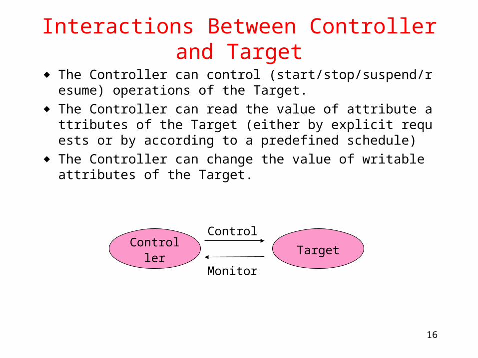
◆ The Controller can control (start/stop/suspend/resume) operations of the Target.
◆ The Controller can read the value of attribute attributes of the Target (either by explicit requests or by according to a predefined schedule)
◆ The Controller can change the value of writable attributes of the Target.
Controller
Control
Monitor
Target
17
Monitor & Control Configurations (1)
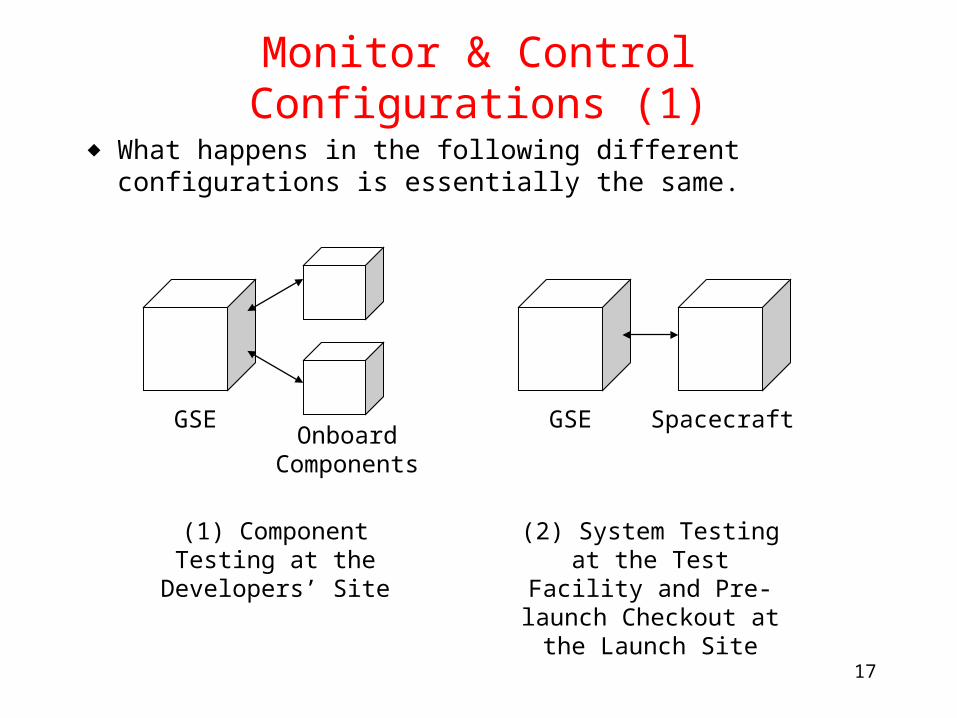
◆ What happens in the following different configurations is essentially the same.
Onboard Components
GSE
(1) Component Testing at the Developers’ Site
SpacecraftGSE
(2) System Testing at the Test Facility and Pre-
launch Checkout at the Launch Site
18
Monitor & Control Configurations (2)
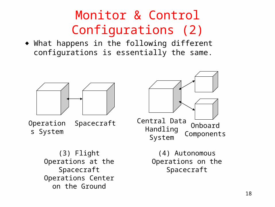
◆ What happens in the following different configurations is essentially the same.
(3) Flight Operations at the Spacecraft
Operations Center on the Ground
Central Data Handling System
(4) Autonomous Operations on the
Spacecraft
SpacecraftOperations System
Onboard Components
19
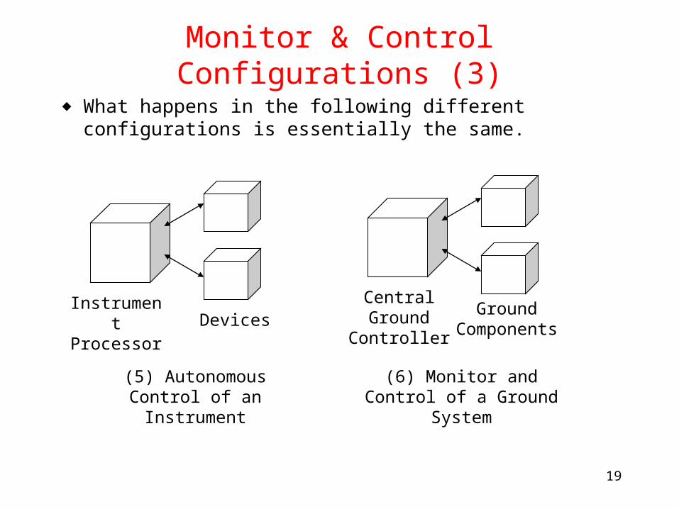
Monitor & Control Configurations (3)
◆ What happens in the following different configurations is essentially the same.
(5) Autonomous Control of an Instrument
Central Ground Controller
(6) Monitor and Control of a Ground System
DevicesInstrument Processor
Ground Components
20
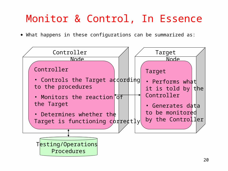
Monitor & Control, In Essence
◆ What happens in these configurations can be summarized as:
Controller Node
Testing/Operations Procedures
Target Node
Controller
• Controls the Target according to the procedures
• Monitors the reaction of the Target
• Determines whether the Target is functioning correctly
Target
• Performs what it is told by the Controller
• Generates data to be monitored by the Controller
21
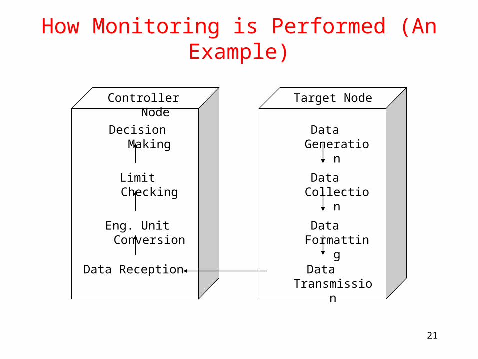
How Monitoring is Performed (An Example)
Target Node
Data Collection
Data Generation
Data Formatting
Data Transmission
Controller Node
Limit Checking
Decision Making
Eng. Unit Conversion
Data Reception
22
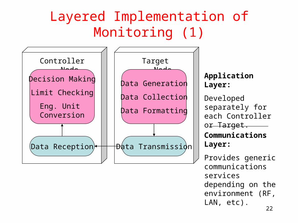
Layered Implementation of Monitoring (1)
Target NodeController Node
Communications Layer:
Provides generic communications services depending on the environment (RF, LAN, etc).
Application Layer:
Developed separately for each Controller or Target.
Data Generation
Data Collection
Data Formatting
Data TransmissionData Reception
Decision Making
Limit Checking
Eng. Unit Conversion
23
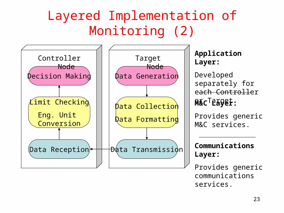
Layered Implementation of Monitoring (2)
Communications Layer:
Provides generic communications services.
Application Layer:
Developed separately for each Controller or Target.
Data TransmissionData Reception
Data Collection
Data Formatting
Data Generation
Limit Checking
Eng. Unit Conversion
Decision Making
M&C Layer:
Provides generic M&C services.
Target NodeController Node
24
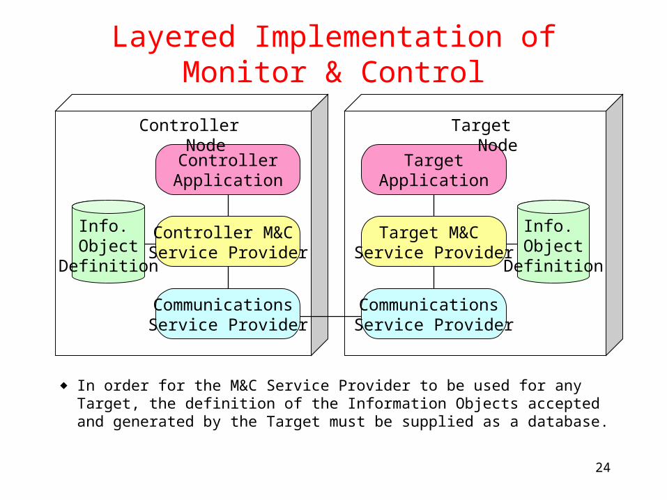
Layered Implementation of Monitor & Control
Target M&C Service Provider
Controller M&C Service Provider
◆ In order for the M&C Service Provider to be used for any Target, the definition of the Information Objects accepted and generated by the Target must be supplied as a database.
TargetApplication
ControllerApplication
Communications Service Provider
Communications Service Provider
Info. Object
Definition
Info. Object
Definition
Target NodeController Node
25
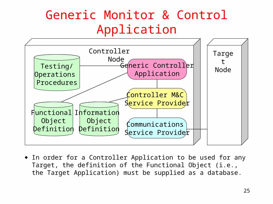
Generic Monitor & Control Application
Controller M&C Service Provider
◆ In order for a Controller Application to be used for any Target, the definition of the Functional Object (i.e., the Target Application) must be supplied as a database.
Generic ControllerApplication
Communications Service Provider
Information Object
Definition
Testing/Operations Procedures
Functional Object
Definition
Target Node
Controller Node
26
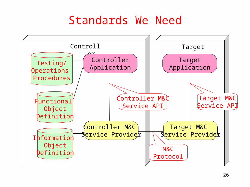
Standards We Need
TargetController
Target M&C Service Provider
Controller M&C Service Provider
TargetApplication
ControllerApplication
Information Object
Definition
Testing/Operations Procedures
Functional Object
Definition
Controller M&CService API
Target M&CService API
M&CProtocol
27
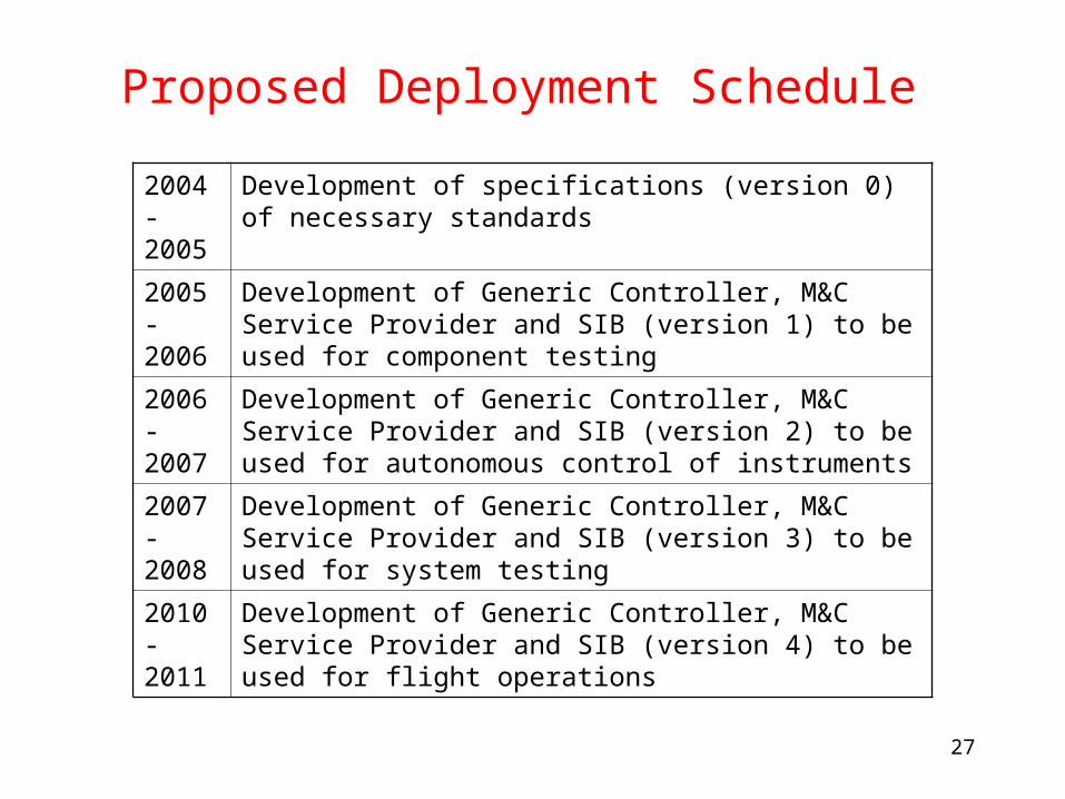
Proposed Deployment Schedule
2004-2005
Development of specifications (version 0) of necessary standards
2005-2006
Development of Generic Controller, M&C Service Provider and SIB (version 1) to be used for component testing
2006-2007
Development of Generic Controller, M&C Service Provider and SIB (version 2) to be used for autonomous control of instruments
2007-2008
Development of Generic Controller, M&C Service Provider and SIB (version 3) to be used for system testing
2010-2011
Development of Generic Controller, M&C Service Provider and SIB (version 4) to be used for flight operations
Recommended


![Spacecraft Simulation]](https://img.pdfslide.us/doc/110x75/544e0a73b1af9f33638b4bf0/spacecraft-simulation.jpg)