44 The Study of Flash Butt Welding of High Si Content Electrical Steel Sheets
The Study of Flash Butt Welding of High Si Content Electrical
Steel Sheets
CHAO-KUN HSIEH
Iron and Steel Research & Development Department China Steel Corporation
As the Si content of electrical steel sheet increased, so did the difficulties of flash butt welding on the pickling line (POL). The Flash Butt Welding (FBW) machine on the POL at China Steel (CSC) was originally designed to weld a Si content of up to 1.5%. Above 2.5% Si, a laser welding machine was suggested by the welding supplier. To conquer this problem, welding parameters adjustments were made in this study. And now the 2.5% Si electrical steel sheets are successfully welded on the pickling line. The mechanisms of broken welds were investigated. The entrapped oxides were found to be the most prominent problems. Welding quality control methods were established in this study to insure the welds quality.
Keywords: Flash butt welding, Electrical steel sheet, Gleeble simulation
1. INTRODUCTION
As the demand for higher, smaller and more efficient electrical motors increases, so has the silicon content added in the electrical steel sheets. To ensure the continuity of production, the steel coils must be welded together. Traditionally, the welding of the steel coils is done by a Flash Butt Welding method. As the Si content of electrical steel sheet gets higher, more difficulties are encountered during flash butt welding.
A flash butt welding machine was used to weld coils on the pickling line. The limit of the steels silicon content that can be welded by this machine is 1.5%.
When the silicon content is higher than 1.5%, a low silicon content steel coil has to be welded to the high silicon content steel to ensure the quality of the weld. The welding supplier only has experience of welding 2.0% Si steel in a laboratory. According to a document from the welding supplier, suggested that laser beam welder might be a better method. Figure 1 shows the welding limits of different welders(1).
Due to the silicon content of the new steel product being up to 2.5%, the optimum operation condition of the welding machine for this steel for flash butt weld-ing was investigated in this study.
China Steel Technical Report, No. 27, pp.43-49, (2014)
Fig.1. Welding limits of different welders(1).
44 The Study of Flash Butt Welding of High Si Content Electrical Steel Sheets
2. EXPERIMENTAL METHODS
2.1 Materials
The test material used was a 2.5% Si electrical steel sheet. A low carbon and low silicon content mate-rial was used to flash butt weld the 2.5% Si electrical steel sheet.
2.2 Flash butt welding process
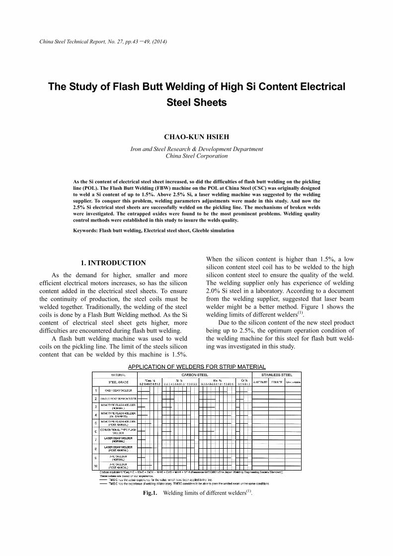
Flash butt welding is a high quality welding process. The welding theory refers to a “Resistance Welding Process”. Flash butt welding is very different to a “Arc Welding Process”; the weld pool is not completely liquidized. The procedure of flash butt welding was introduced as shown in Fig.2.
2.3 Flash butt welding on pickling line
The flash butt welding of 2.5% Si electrical steel was performed on the Pickling Line. The silicon con-tent was far beyond the welding limits of the welder supplier’s operation manual, there were no suitable welding parameters that could be used. In order to establish the optimum welding parameters, the L8 Orthogonal Array (OA) of the Design Of Experiments (DOE) was used. Four factors were chosen as follows: (1) Upset length - shorter, longer. (2) Flash time - shorter, longer. (3) Upset current - lower, higher. (4) Upset pressure - lower, higher.
The set-up of the L8 Orthogonal Array is shown in Table 1.
A. Electrodes clamp the metal that is to be welded.
B. The movable electrode moves. A welding current is applied to the
metal.
C. Flash stage. The gap between the two pieces of metal cause resis-
tance, producing an arc. The uneven edges of the metal are moved
so called “Burn-off”. This is the main welding heat source. The
movable electrode moves forward.
D. Upset stage. The movable electrode moves together rapidly.
Squeezing out the melted steel and interfacial oxides. The metal
joins.
E1. The welding current is turned off.
E2. The flare is shaved away.
The flash butt welding process is complete.
Fig.2. Flash butt welding process.
45 Chao-Kun Hsieh
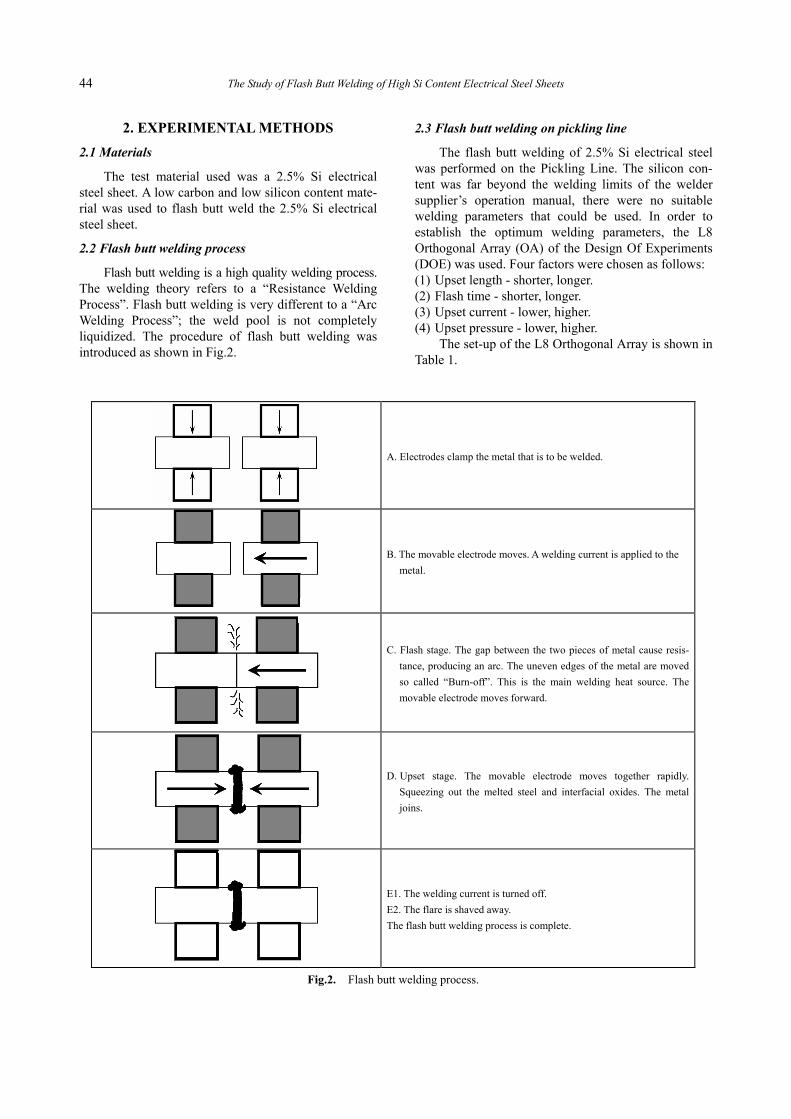
2.4 Bulge test on pickling line
The bulge test was the on-site fast quality control method, which was used to ensure the welding quality passed the Pickling Line with no broken welds. The bulge test was shown as Fig.3.
Pass
Fail
Fig.3. Bulge Test.
2.5 Laboratory experiment
The Gleeble 1500 was used to simulate the coarse grain structure of high Si electrical steel after welding. A mechanical test was performed to understand the relationship of coarse grain and weld brittle fracture. Weld fracture analysis was carried out to establish the causes of fracture in the flash butt welding. Optical microscopy and SEM observations were performed to distinguish the quality of the welds.
3.RESULTS AND DISCUSSION
3.1 Results of the L8 orthogonal array tests
L8 orthogonal array test results are shown in Table 2. The results indicated the influence of each parameter. (1) Upset length - longer one has better effect, signifi-
cant effect. (2) Flash time - longer one has better effect. (3) Upset current - higher one has better effect, not
significant. (4) Upset pressure - not significant. (5) Upset length and upset pressure have interaction;
longer upset length matches with higher upset pres-sure.
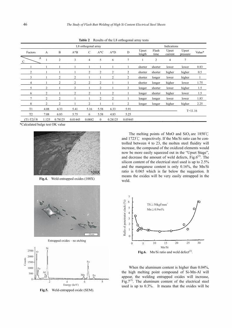
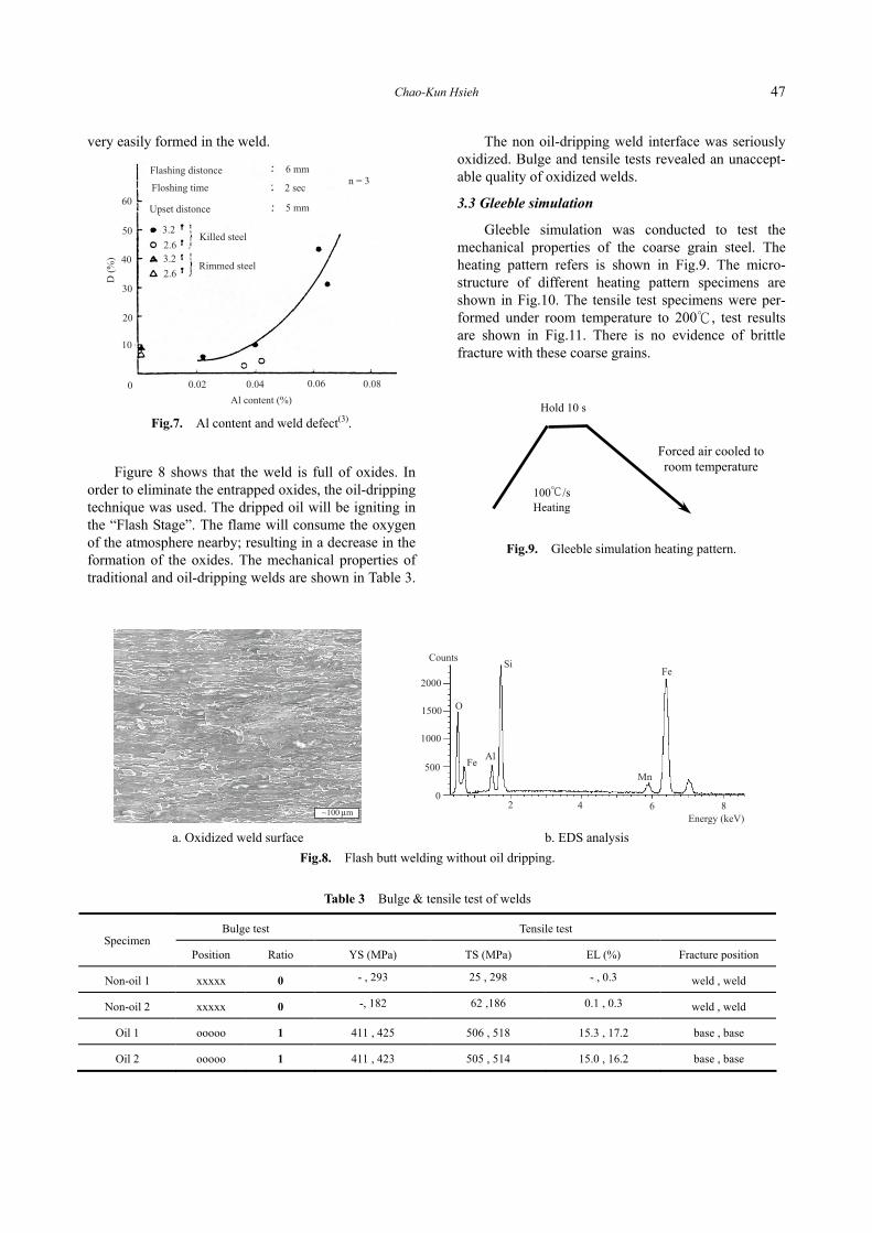
3.2 Interfacial oxides
The silicon is an element that is easily oxidized. Due to the flash butt welding process being performed in an open atmosphere, silicon oxides were easily found in the weld of high silicon steel. If the silicon oxides were not squeezed out thoroughly, the entrapped oxides would become the origin for fracture initiation. The weld-entrapped oxide is shown in both Figs.4 and 5.
Table 1 L8 orthogonal array
L8 orthogonal array
Factors A B A*B C A*C A*D D
A
C 1 2 3 4 5 6 7
1 1 1 1 1 1 1 1
2 1 1 1 2 2 2 2
3 1 2 2 1 1 2 2
4 1 2 2 2 2 1 1
5 2 1 2 1 2 1 2
6 2 1 2 2 1 2 1
7 2 2 1 1 2 2 1
8 2 2 1 2 1 1 2
46 The Study of Flash Butt Welding of High Si Content Electrical Steel Sheets
Fig.4. Weld-entrapped oxides (100X)
Entrapped oxides – no etching
Fig.5. Weld-entrapped oxide (SEM).
The melting points of MnO and SiO2 are 1850℃ and 1723℃ respectively. If the Mn/Si ratio can be con-trolled between 4 to 23, the molten steel fluidity will increase, the compound of the oxidized elements would now be more easily squeezed out in the “Upset Stage”, and decrease the amount of weld defects, Fig.6(2). The silicon content of the electrical steel used is up to 2.5% and the manganese content is only 0.16%, the Mn/Si ratio is 0.065 which is far below the suggestion. It means the oxides will be very easily entrapped in the weld.
Fig.6. Mn/Si ratio and weld defect(2).
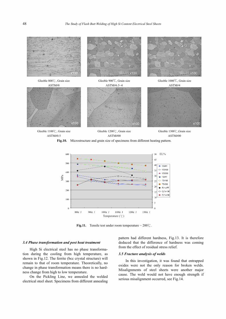
When the aluminum content is higher than 0.04%, the high melting point compound of Si-Mn-Al will appear, the welding entrapped oxides will increase, Fig.7(3). The aluminum content of the electrical steel used is up to 0.3%. It means that the oxides will be
Table 2 Results of the L8 orthogonal array tests
L8 orthogonal array Indications
Factors A B A*B C A*C A*D D Upset length
Flash time
Upset current
Upset pressure
Value*
AC
1 2 3 4 5 6 7 1 2 4 7
1 1 1 1 1 1 1 1 shorter shorter lower lower 0.83
2 1 1 1 2 2 2 2 shorter shorter higher higher 0.5
3 1 2 2 1 1 2 2 shorter longer lower higher 1
4 1 2 2 2 2 1 1 shorter longer higher lower 1.75
5 2 1 2 1 2 1 2 longer shorter lower higher 1.5
6 2 1 2 2 1 2 1 longer shorter higher lower 1.5
7 2 2 1 1 2 2 1 longer longer lower lower 1.83
8 2 2 1 2 1 1 2 longer longer higher higher 2.25
T1 4.08 4.33 5.41 5.16 5.58 6.33 5.91
T2 7.08 6.83 5.75 6 5.58 4.83 5.25 T=11.16
(T1-T2)2/8 1.125 0.78125 0.01445 0.0882 0 0.28125 0.05445
*Calculated bulge test OK value
47 Chao-Kun Hsieh
very easily formed in the weld.
Fig.7. Al content and weld defect(3).
Figure 8 shows that the weld is full of oxides. In order to eliminate the entrapped oxides, the oil-dripping technique was used. The dripped oil will be igniting in the “Flash Stage”. The flame will consume the oxygen of the atmosphere nearby; resulting in a decrease in the formation of the oxides. The mechanical properties of traditional and oil-dripping welds are shown in Table 3.
The non oil-dripping weld interface was seriously oxidized. Bulge and tensile tests revealed an unaccept-able quality of oxidized welds.
3.3 Gleeble simulation
Gleeble simulation was conducted to test the mechanical properties of the coarse grain steel. The heating pattern refers is shown in Fig.9. The micro-structure of different heating pattern specimens are shown in Fig.10. The tensile test specimens were per-formed under room temperature to 200℃, test results are shown in Fig.11. There is no evidence of brittle fracture with these coarse grains.
Fig.9. Gleeble simulation heating pattern.
100℃/s Heating
Hold 10 s
Forced air cooled to room temperature
a. Oxidized weld surface
b. EDS analysis
Fig.8. Flash butt welding without oil dripping.
Table 3 Bulge & tensile test of welds
Bulge test Tensile test Specimen
Position Ratio YS (MPa) TS (MPa) EL (%) Fracture position
Non-oil 1 xxxxx 0 - , 293 25 , 298 - , 0.3 weld , weld
Non-oil 2 xxxxx 0 -, 182 62 ,186 0.1 , 0.3 weld , weld
Oil 1 ooooo 1 411 , 425 506 , 518 15.3 , 17.2 base , base
Oil 2 ooooo 1 411 , 423 505 , 514 15.0 , 16.2 base , base
48 The Study of Flash Butt Welding of High Si Content Electrical Steel Sheets
3.4 Phase transformation and post heat treatment
High Si electrical steel has no phase transforma-tion during the cooling from high temperature, as shown in Fig.12. The ferrite (bcc crystal structure) will remain to that of room temperature. Theoretically, no change in phase transformation means there is no hard-ness change from high to low temperature.
On the Pickling Line, we annealed the welded electrical steel sheet. Specimens from different annealing
pattern had different hardness, Fig.13. It is therefore deduced that the difference of hardness was coming from the effect of residual stress relief.
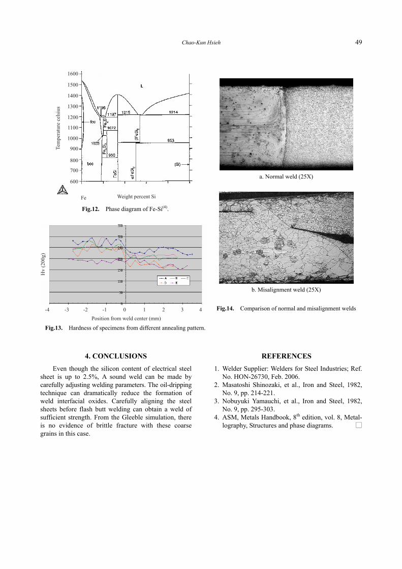
3.5 Fracture analysis of welds
In this investigation, it was found that entrapped oxides were not the only reason for broken welds. Misalignments of steel sheets were another major cause. The weld would not have enough strength if serious misalignment occurred, see Fig.14.
Gleeble 800℃, Grain size
ASTM#8
Gleeble 900℃, Grain size
ASTM#6.5~4
Gleeble 1000℃, Grain size
ASTM#4
Gleeble 1100℃, Grain size
ASTM#0.5
Gleeble 1200℃, Grain size
ASTM#00
Gleeble 1300℃,Grain size
ASTM#00
Fig.10. Microstructure and grain size of specimens from different heating pattern.
Fig.11. Tensile test under room temperature ~ 200℃.
49 Chao-Kun Hsieh
4. CONCLUSIONS
Even though the silicon content of electrical steel sheet is up to 2.5%, A sound weld can be made by carefully adjusting welding parameters. The oil-dripping technique can dramatically reduce the formation of weld interfacial oxides. Carefully aligning the steel sheets before flash butt welding can obtain a weld of sufficient strength. From the Gleeble simulation, there is no evidence of brittle fracture with these coarse grains in this case.
REFERENCES
1. Welder Supplier: Welders for Steel Industries; Ref. No. HON-26730, Feb. 2006.
2. Masatoshi Shinozaki, et al., Iron and Steel, 1982, No. 9, pp. 214-221.
3. Nobuyuki Yamauchi, et al., Iron and Steel, 1982, No. 9, pp. 295-303.
4. ASM, Metals Handbook, 8th edition, vol. 8, Metal-lography, Structures and phase diagrams. □
Fig.12. Phase diagram of Fe-Si(4).
Fig.13. Hardness of specimens from different annealing pattern.
a. Normal weld (25X)
b. Misalignment weld (25X)
Fig.14. Comparison of normal and misalignment welds
Recommended