The roadmap of educational process renovation through CALS-technologies and project-oriented learning methods Design notes for “Fab Lab” workshop project
Cech-4 workshop
Design by Daler Arabov 2016BMSTU, Department IU4 “Electronic Equipment Design and Technology”
version of 20.02.17 03:09

2
Содержание
Fabrication laboratoty (fab lab) 3
Workshop equipment 4
Example works 5
General production process 6
Educational process renovation 7
Project-oriented learning method 8
Circuit (functional) design segment 9
Design segment 10
Educational segment of process planning 11
Software 12
IT-infrastracture 13
Workspace layout 14
Business model 15
Roadmap of Cech-N project 16
Equipment specifications 17
Contact info 18
3Fab lab — is a concept for unifying a compact digital workshop, a design office and an educational facility. The Russian terms for it are “Youths’ center of innovative creative activity” and “Center of technological support of education”.
The area of expertise of our department is electronic equipment design and technology. The purpose of Cech-4 workshop is development and fast prototyping of electronics and midsize mechanics and robotics.
Fabrication laboratoty (fab lab)
3
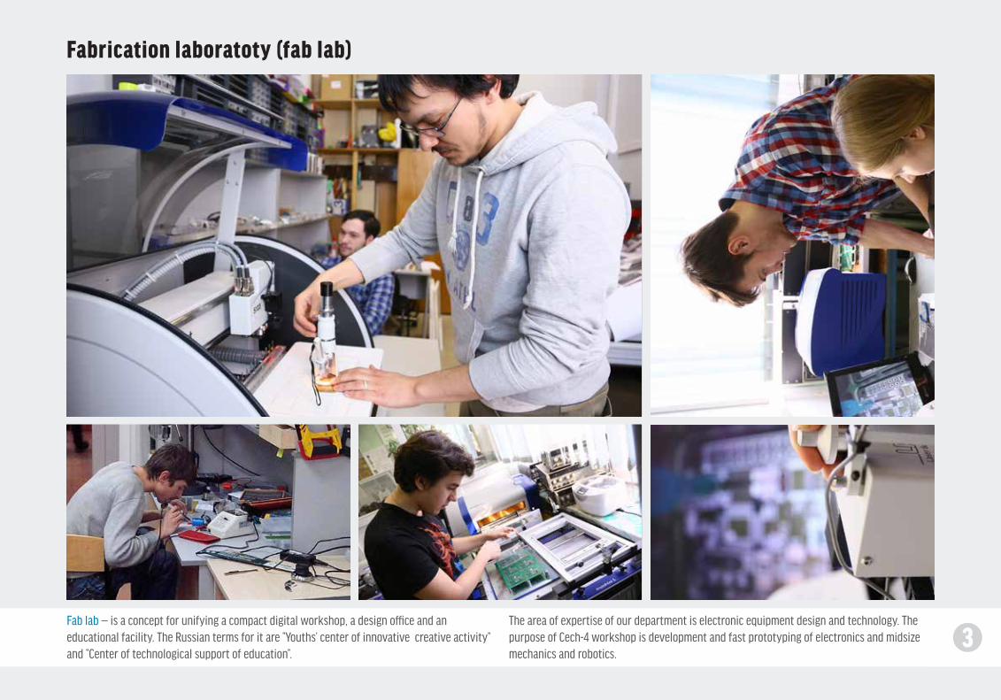
4The core equipment uses CNC and enables a full production cycle of electronics. Equipment’s specifications are outlined on p. 17.The defining principles of the workshop are compactness, modularity, versatility, ease of use and environmental friendliness.
Workshop equipment
Pic. 1. LPKF Protomat PCB milling machine Pic. 2. LPKF Protoprint stencil printer Pic. 4. LPKF ProtoFlow convection ovenPic. 3. LPKF Protoplace SMT assembly equipment
Pic. 7. Trotec Speedy laser engraver Pic. 8. KPOH workbenchPic. 6. Stratasys Fortus 3D printerPic. 5. VHF CAM PCB milling machine
Pic. 9. Vibration simulation system Pic. 10. IRTIS thermal imager Pic. 11. Electric measurement equipment Pic. 12. Mitutoyo precision metrology equipment
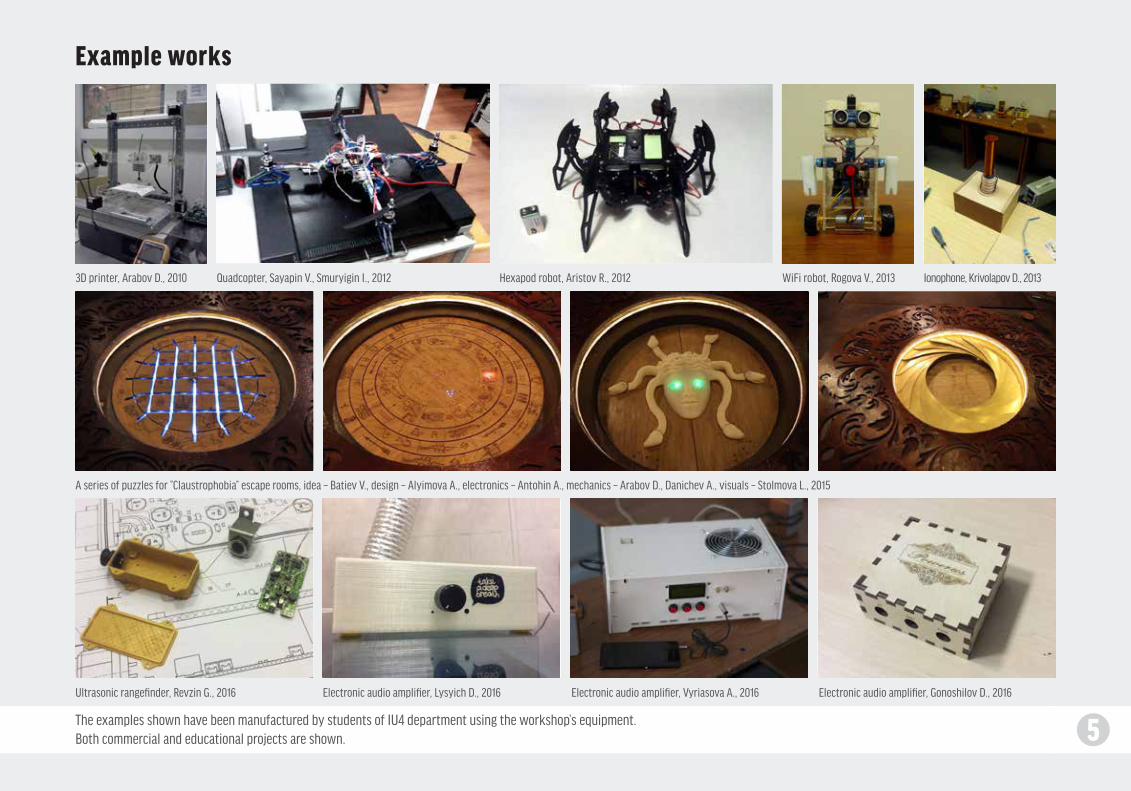
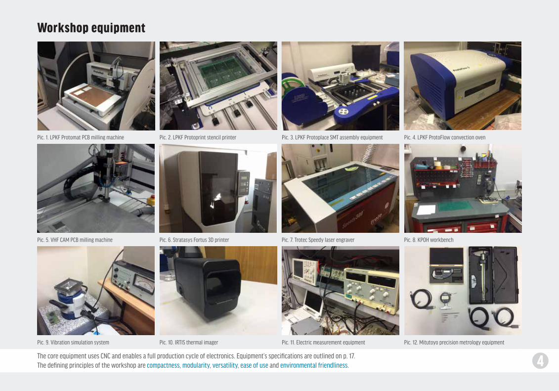
5The examples shown have been manufactured by students of IU4 department using the workshop’s equipment.Both commercial and educational projects are shown.
Example works
3D printer, Arabov D., 2010
A series of puzzles for “Claustrophobia” escape rooms, idea – Batiev V., design – Alyimova A., electronics – Antohin A., mechanics – Arabov D., Danichev A., visuals – Stolmova L., 2015
Ultrasonic rangefinder, Revzin G., 2016 Electronic audio amplifier, Lysyich D., 2016 Electronic audio amplifier, Vyriasova A., 2016 Electronic audio amplifier, Gonoshilov D., 2016
Quadcopter, Sayapin V., Smuryigin I., 2012 Hexapod robot, Aristov R., 2012 WiFi robot, Rogova V., 2013 Ionophone, Krivolapov D., 2013
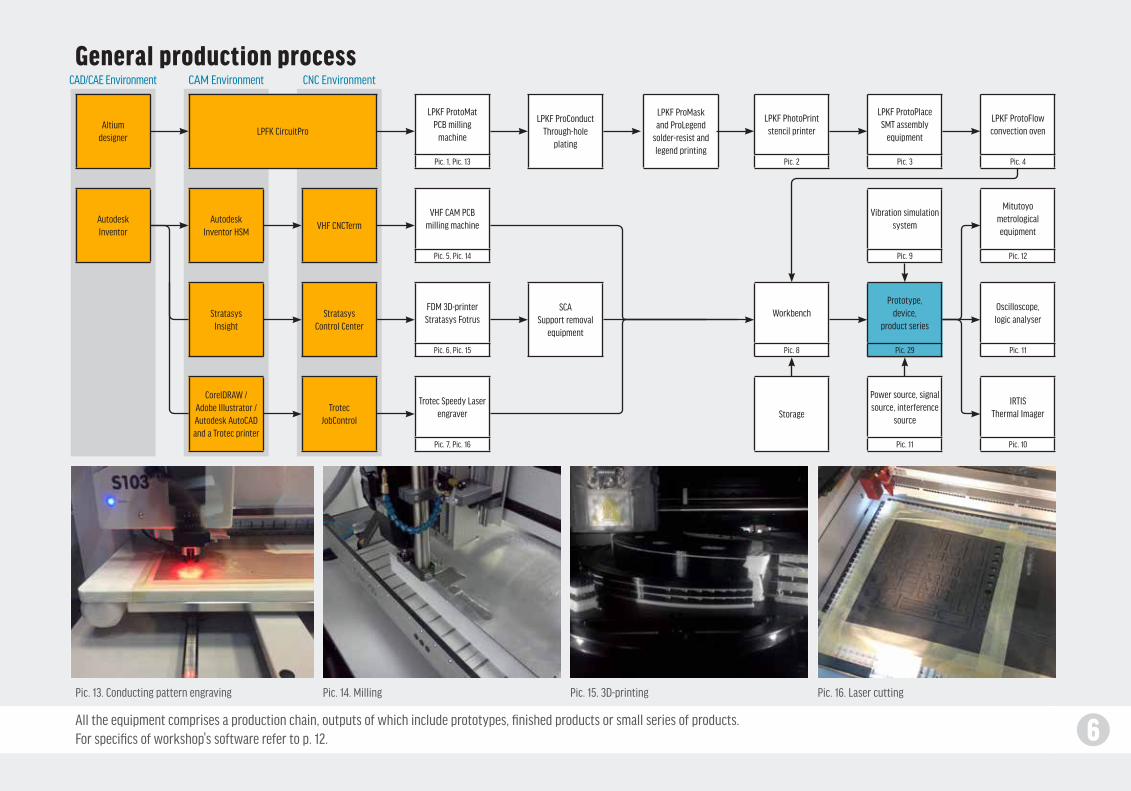
6All the equipment comprises a production chain, outputs of which include prototypes, finished products or small series of products.For specifics of workshop's software refer to p. 12.
General production process
Pic. 13. Conducting pattern engraving Pic. 15. 3D-printing Pic. 16. Laser cuttingPic. 14. Milling
Altium designer
Autodesk Inventor
LPFK CircuitProLPKF ProConduct
Through-hole plating
LPKF ProMaskand ProLegend
solder-resist andlegend printing
Storage
Autodesk Inventor HSM
VHF СNCTerm
SCASupport removal
equipment
Stratasys Control Center
Stratasys Insight
Trotec JobControl
CorelDRAW / Adobe Illustrator / Autodesk AutoCAD and a Trotec printer
CAD/CAE Environment CAM Environment СNC Environment
LPKF ProtoMat PCB milling
machine
Pic. 1, Pic. 13
VHF CAM PCB milling machine
Pic. 5, Pic. 14
FDM 3D-printer Stratasys Fotrus
Pic. 6, Pic. 15
Workbench
Pic. 8
Vibration simulation system
Pic. 9
Mitutoyometrological equipment
Pic. 12
Prototype, device,
product series
Pic. 29
Power source, signal source, interference
source
Pic. 11
Oscilloscope,logic analyser
Pic. 11
IRTISThermal Imager
Pic. 10
Trotec Speedy Laser engraver
Pic. 7, Pic. 16
LPKF PhotoPrint stencil printer
Pic. 2
LPKF ProtoPlaceSMT assembly
equipment
Pic. 3
LPKF ProtoFlow convection oven
Pic. 4
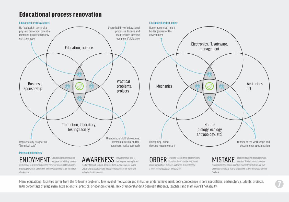
7Many educational facilities suffer from the following problems: low level of motivation and initiative, underachievement, poor competence in core specialities, perfunctory students' projects: high percentage of plagiarism, little scientific, practical or economic value, lack of understanding between students, teachers and staff, overall negativity.
Educational process renovation
Education, scienceElectronics, IT, software,
management
Production, laboratory, testing facility
Nature(biology, ecology, antropology, etc)
Practical problems, projects
Aesthetics, art
Business, sponsorship Mechanics
Unprofitability of educational processes. Repairs and maintenance increase equipment's idle time
No feedback in terms of a physical prototype, potential mistakes, projects that only exists on paper
Non-ergonomical, might be dangerous for the environment
Unoptimal, unskillful solutions: overcomplication, clutter,
bugginess, hacky approachOutside of the workshop's and
department's specialisationImpracticality, stagnation, "Spherical cow"
Educational process should be
enjoyable and fulfilling: students
are supposed to be seeking enjoyment from their studies and teachers are
the ones providing it. Gamification and innovative elements are the sources
of enjoyment
Every action must have a
clear purpose. Meaningfulness
is achivied thfough analysis, discussion, hand-on experience and search.
Logical fallacies such as relying on tradiotion, catering to the majority or
authority should be avoided
Everyone should strive for order in any
situation. Order must be established
in our surroundings, business and minds. It must become
a foundation of education and activities
Students should not be afraid to make
mistakes. Teachers should know the
mistakes and their reasons, introduce them to their students and give
contextual knowledge. Teacher and student analyze mistakes and create
feedback
Uninspiring, bland, gives no reason to use it
Educational process aspects
Motivational engines
Educational project aspect
ENJOYMENT AWARENESS ORDER MISTAKE
7
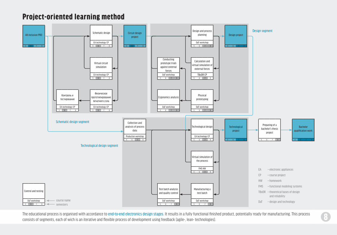
8The educational process is organised with accordance to end-to-end electronics design stages. It results in a fully functional finished product, potentially ready for manufacturing. This process consists of segments, each of wich is an iterative and flexible process of development using feedback (agile-, lean- technologies).
Project-oriented learning method
Контроль и тестирование
EA technology CP5 6 7 8
Control and testing
DaT workshop5 6 7 8
Физическое прототипирование
печатного узла
EA technology CP5 6 7 8
Virtual circuit simulation
EA technology CP5 6 7 8
Schematic design
EA technology CP5 6 7 8
Conducting prototype trials against external
forcesDaT workshop
5 6 7 8
Ergonomics analysis
DaT workshop5 6 7 8
Test batch analysis and quality control
DaT workshop5 6 7 8
Physical prototyping
DaT workshop5 6 7 8
Manufacturing a test batch
DaT workshop5 6 7 8
Calculation and virtual simulation of
external forces
TBoDR CP5 6 7 8
Virtual simulation of the process
FMS HW5 6 7 8
Design and process planning
DaT workshop5 6 7 8
Technological design
EA technology CP5 6 7 8
Collection and analysis of process
data
Production workshop5 6 7 8
All-inclusive PRD
5 6 7 8
Circuit design project
5 6 7 8
Bachelor qualification work
5 6 7 8
Preparing of a bachelor's thesis
project
5 6 7 8
Design project
5 6 7 8
Technological project
5 6 7 8
Schematic design segment
Technological design segment
EA — electronic appliances
CP — course project
HW — homework
FMS — functional modeling systems
TBoDR — theoretical bases of design and reliability
DaT — design and technology
Design segment
course name semesters

9Circuit design in a broad sense is represented by functional design which serves to develop a functional prototype of a device or a system.This includes creating system architecture, circuit design, software, UI and machine interfaces.
Circuit (functional) design segment
Pic. 17. Altium Designer Pic. 18. Breadboard assembly Pic. 19. Chemical etching Pic. 20. Milling Pic. 21. Structural design Pic. 22. PCA prototype
All-inclusive PRD (iteration 1)
Task analysis, working out the
requirements
Field of application analyzing,
generating solutions
Virtual circuit simulation
Testing, finding weak points and errors
Circuit design documentaion
package
EDA source files package
Revised PRD (iteration 2)
Physical prototyping of PCA
Circuit design using EDA
Pic. 17
Using breadboards
Pic. 18
PCA prototype
Pic. 22
Aggregation ofproject info,
preparingdocumentation
Pic. 21
Chimical etching
Pic. 19
Milling
Pic. 20
Prototyping methods
Circuit design project
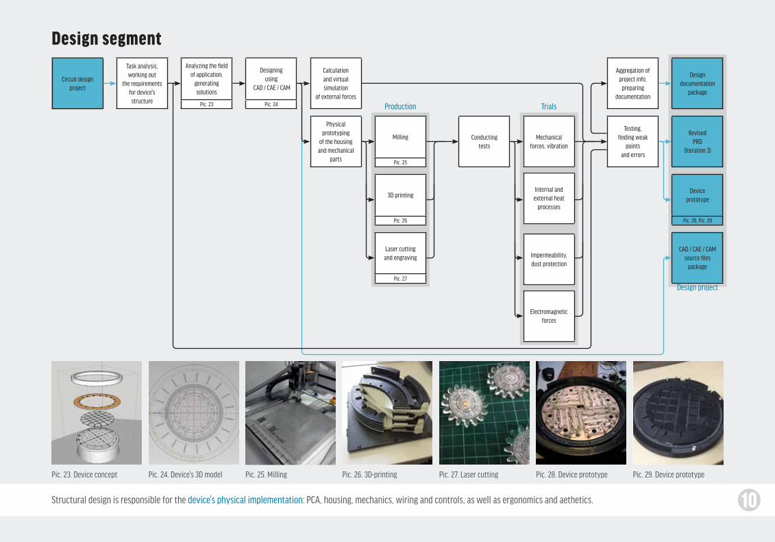
10Structural design is responsible for the device's physical implementation: PCA, housing, mechanics, wiring and controls, as well as ergonomics and aethetics.
Design segment
Circuit designproject
Task analysis,working out
the requirements for device's structure
Designdocumentation
package
CAD / CAE / CAMsource files
package
RevisedPRD
(Iteration 3)
Physicalprototyping
of the housingand mechanical
parts
Calculationand virtualsimulation
of external forces
Conductingtests
Aggregation ofproject info,
preparingdocumentation
Internal andexternal heat
processes
Impermeability,dust protection
Electromagneticforces
Mechanicalforces, vibration
Testing,finding weak
pointsand errors
Designingusing
CAD / CAE / CAM
Pic. 24
Analyzing the field of application,
generatingsolutions
Pic. 23
Milling
Pic. 25
Deviceprototype
Pic. 28, Pic. 29
3D printing
Pic. 26
Laser cuttingand engraving
Pic. 27
Design project
TrialsProduction
Pic. 23. Device concept Pic. 24. Device's 3D model Pic. 25. Milling Pic. 26. 3D-printing Pic. 27. Laser cutting Pic. 28. Device prototype Pic. 29. Device prototype
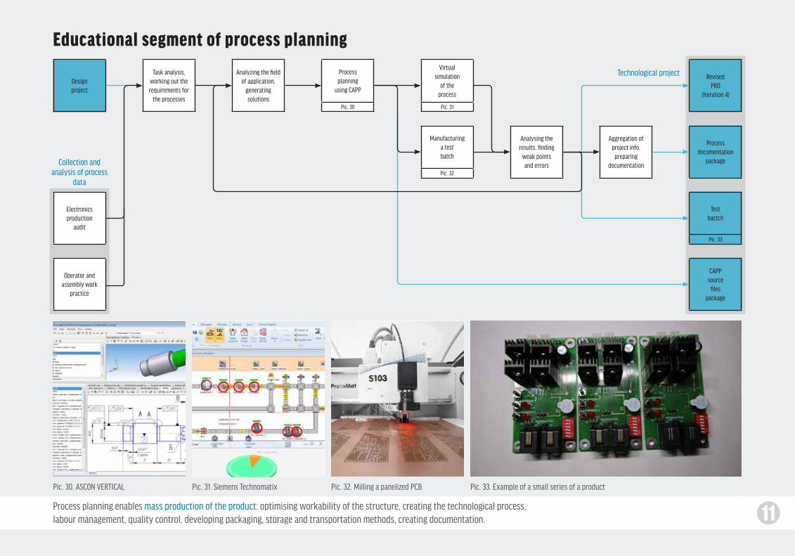
11Process planning enables mass production of the product: optimising workability of the structure, creating the technological process,labour management, quality control, developing packaging, storage and transportation methods, creating documentation.
Educational segment of process planning
Pic. 30. ASCON VERTICAL Pic. 31. Siemens Technomatix Pic. 33. Example of a small series of a productPic. 32. Milling a panelized PCB
Designproject
Electronicsproduction
audit
Operator andassembly work
practice
Task analysis,working out therequirements for
the processes
Analyzing the field of application,
generatingsolutions
Processdocumentation
package
CAPPsource
filespackage
RevisedPRD
(Iteration 4)
Analysing theresults, finding
weak pointsand errors
Aggregation ofproject info,
preparingdocumentation
Processplanning
using CAPP
Pic. 30
Manufacturinga testbatch
Pic. 32
Virtual simulation
of the process
Pic. 31
Testbactch
Pic. 33
Technological project
Collection and analysis of process
data
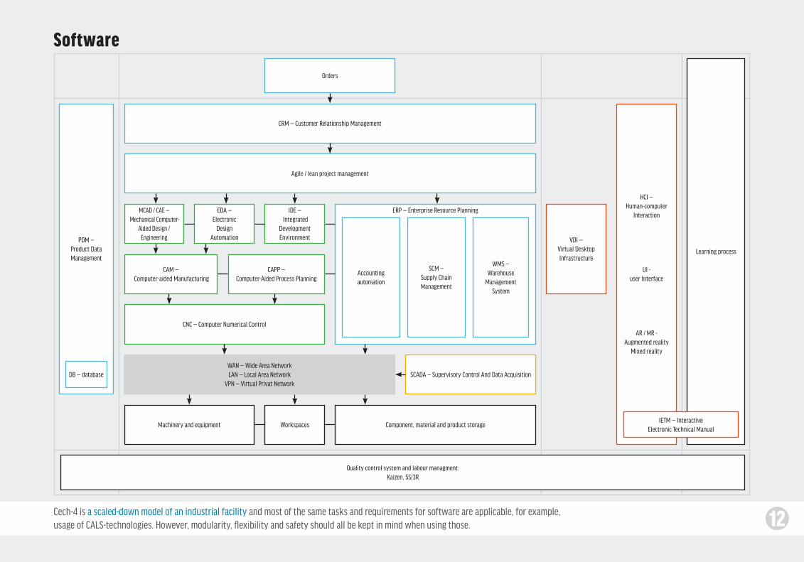
12Cech-4 is a scaled-down model of an industrial facility and most of the same tasks and requirements for software are applicable, for example, usage of CALS-technologies. However, modularity, flexibility and safety should all be kept in mind when using those.
Software
CRM — Customer Relationship Management
Orders
PDM — Product DataManagement
DB — database
Agile / lean project management
MCAD / CAE — Mechanical Computer-
Aided Design / Engineering
CAM — Computer-aided Manufacturing
CNC — Computer Numerical Control
Machinery and equipment
Quality control system and labour managment:Kaizen, 5S/3R
Workspaces Component, material and product storage
WAN — Wide Area NetworkLAN — Local Area Network
VPN — Virtual Privat Network
CAPP — Computer-Aided Process Planning
WMS — Warehouse
Management System
SCM — Supply Chain Management
Accountingautomation
EDA —Electronic
Design Automation
IDE — Integrated
Development Environment
HCI — Human-computer
Interaction
UI -user Interface
AR / MR -Augmented reality
Mixed reality
Learning process
VDI — Virtual Desktop Infrastructure
IETM — Interactive Electronic Technical Manual
SCADA — Supervisory Control And Data Acquisition
ERP — Enterprise Resource Planning

13The workshop's infrastructure is based on three principles: 1) safety and remote control of manufacturing processes — reduces the workload of staff, makes personal control unnecessary; 2) virtualization — simplifies network administration and staff interaction; 3) interactive environment — allows for convenient and efficient info presentation and processing.
Manufacturingequipment
Mobile platform
External server
Local PC
IT-infrastructure
Terminal, thin client
Control PC
Local server, VDI-Platform
Dependantequipment
Equipment control and safety Workplace control and safety
Autonomousequipment
External PC
SCADA
SCADA
VPN
GSM
CRM ERP
ERP
PDM
PDM
External data storage
Local data storage
Клиент VDI
VDI client
Virtual PC
SCADAclient
Interactive environment
CAM
CAD
CADVideointerface:
monitor, projector, cameraSensory interfaces:
interactive board, tableVoice interface:
microphones, speakersNeurointerface
Augmented \ mixed realityinterface: AR-glasses, holograms
CNC
Power controller Power subnetwork
Camera Surveillance
Fire extinguishingsystem
Ventilation
Lighting
Microphone
Thermometer
Climate control
Gas sensors (CO, CO2)
CAD
CAD
CAD
CAM
WAN
LAN
clothing that lights up and responds to how you move or responds to people around you musical instruments
If we’re making a robot that's supposed to move
towards the lighT
that's often done today with a “knob”.
We try it on this setting…
it might need a setting, to say how sensitive it should be to the light.
Why not work in an environment where, instead of choosing one particular setting —
— we see across an entire range at once.
If that doesn’t work too well, we try it on this setting…
It’s very ad hoc, very unsystematic.
We say “go”, and the room and the material work together to do a test run at that setting, collect the data —
then automatically try the next one, and the next one —
Go through the entire range, try them all out, collect all the data.
then we just look and see what actually happened in all those cases.
We can take measurements, reduce the data, figure out which is the best alternative.
And not just which is the best, but why it's the best.
We can see all the context.
I've seen so many projects fail at some point because some wire came loose.
The conventional thinking is that it's the fault of the builder for not attaching the wire strongly enough.
The way I see it, it's the fault of the wire for being too dumb to know whether it's attached.
the bare minimum processing power
the bare minimum communications capability
As a result, most of the information we’d actually want
to see is never collected or
accessible in the first place.
For years, I’ve been designing tools.
My focus has always been — how can creators see that behavior?
tools for people making software…
How can they see what the thing they're building is actually doing?
These have generally been software-based tools.
What “software-based” means today is that these tools are trapped inside a tiny rectangle that sits on your desk. To do your work, you sit at your desk
and you stare at this tiny rectangle.
And this frustrates me.
things with complex behavior.
so they can understand what it’s doing?
real-world Tools are in rooms, where workers think with their bodies.
software-based Tools are trapped in tiny rectangles.
For example, say we’re making this little robot which is supposed to move towards the light.
What do we do?
We have to get in there!
We have to get inside that robot's head, and see what it's seeing, and see what it's thinking, and come to understand
why it's behaving the way it's behaving.
What we need are seeing tools.
We don't have many of those.
And the few we have are very primitive tiny rectangles that sit on a desk.
We turn on the light…
and… it does not move toward the light.
The construction tools won't help us here.
why A seeing space? What is a seeing space?
Today’s maker spaces provide tools for building.
modern projects have complex behavior.
The challenge is not building these projects, but understanding them.
understanding requires seeing, and the best seeing tools are rooms.
These kinds of projects have high internal complexity (often with embedded software)
With these projects, the primary challenge is not putting the pieces together.
the primary challenge is understanding what the thing is doing
They're often taking input from the outside world
giving rise to complex behavior.
and why it's doing that and how we can get it to do what we actually want it do.
We now live in a world where sensors are cheap,
processing is cheap.
We need to start working with smarter materials
And then the room is designed to reflect all that information back to us — so anything we’d want to know is just a glance away.
and responding to the world in complex ways.
For example, here's how NASA does it. If you're launching a space shuttle, you need to understand everything that's going on in this very complex system.
So, they install sensors everywhere, and they design a room where they can see and understand and control every part of the system.
a waste treatment facility
On the other hand, there are some people that take seeing very seriously.
this is the california power grid a canadian power grid
a tv stationthe large hadron collider at CERN, where they
recently found the higgs boson.
These people know that if we’re trying to design a system of this complexity, a system that we have to understand in realtime, we need a room — where we can be immersed in seeing tools.
and robots that fly around robots you can talk to robots that tend your gardenToday, people are making things like —robots that roll around
And what are powerful ways of seeing
… electronics, music, animation, mathematical systems…
welding equipment, plastic-forming equipmenta laser cutter
a 3d printer
lathes, mills, drills sawing, sewing, soldering
If you walk into a maker space today, you'll probably see —
that's the kind of thinking that I'd like to bring to mainstream engineering and making.
a room-sized microscope that we’re embedded inside, designed entirely around seeing and understanding what the project we’re building is actually doing.
I'd like to take this idea of a maker space, and transition it to a seeing space.
Shifting the focus from putting the pieces together to deep understanding.
I think about seeing on three levels — three progressively more powerful ways of seeing.
We tend to see things moment-to-moment, think moment-to-moment. It's not until we step back from those moments
and look across a range of time
at once…
that we can start to notice patterns,
and think about systemic causes.
Say we turn on our robot and it does something interesting here. The moment goes past but we want to grab it and run it back.
Why not? Why not work in a space with video cameras everywhere. everything is recorded, everything is marked and tracked.
collecting data
displaying data
controlling time
seeing across time
automatic notebook
automatic experimentation
And search the project’s history. If a sensor reading seems high…
just look up, grab time
Put control of time
And look across a range of time at once.
See the path the robot took.
see all the data collected during the run. see what the sensors saw, see the internal variables. Compare what happened
this time to what happened last time.
Understand the effects of changes.
first, before we can see anything, we see something to see. We need a way of collecting data, and a way of displaying that data.
Seeing Inside1 Seeing Across Time2 Seeing Across Possibilities3
run it back, see what happened.
into the maker's hands.
All of this data can be stored forever, because digital storage today is free. So the entire history of the project can automatically become a notebook.
browse the project’s history.
See all the video, all the data, all the notes that we took.
examine sessions in the past where that sensor reading was also high.
There's an even more powerful way of seeing, which is seeing across different design alternatives. Do we make the robot behave like this or like that? We see it both ways, and compare them.Now, we can think about how to display the data. What are powerful ways of representing this information? one of the most powerful ways is to show time.
Just the bare minimum of sensors
that collect a lot of data about the internal state
and collect data about the external environment
and transmit that data up to the room.
Say we’re making this little robot.
it would typically be built with a kind of “20th-century stinginess” —
where the worker is surrounded by tools
where they walk around
where they think spatially.
The room becomes a macro-tool they're embedded inside an extension
of the body.
So, I've been taken with this idea of designing tools in the form of rooms. This led to thinking
about maker spaces.
with access to high-end equipment that would be too expensive for individuals.
I like these two aspects of maker spaces…
and I like the philosophical motivations behind the “maker movement” —
if you think about many traditional forms of craftsmanship, they take place in a spatial environment — a room — designed for that purpose
use their body, use their hands
Maker spaces are communal workshops where people come together to create in a shared social environment
instead of consuming mass-produced products, people should make their own things.
This talk is about a way to take these maker goals to the next level
by designing a new kind of space that enables and empowers creators in ways that today's workspaces don't support.
These are wonderful tools, but these are all construction tools.
These are tools for sticking material together.
These are just the tools you need if you're making, say, furniture or simple mechanical contraptions.
But more and more, the projects that people want to make are of a different kind…
bike displays book scanners 3d printers self-balancing vehicles
tinkering is where we’re trying things out, trying to find something that seems to work.
engineering is where we do understand the underlying principles. We do have a clear model of why something works.
In the scientific way of thinking, we’re discovering and articulating those underlying principles. We’re generating that theory that engineering relies on — building those models.
with building tools
and conceptual tools
and seeing tools
tinkering scienceengineering
why is seeing so important?
the way I see it, “making” exists on a spectrum. There are these different ways of thinking that we draw on, in different combinations, at different times —
tinkering scienceengineering
if you just give someone “making” tools, and teach them how to use them, they can work in this range.
And if you then give them theory, now they can work across this range.
but to span this entire space — to draw on all these ways of thinking at once — they need tools to see what’s really happening and make sense of it.
So we have this theoretical knowledge guiding our design decisions — very powerful. But this theory often comes from something like a textbook. how do we work in a domain where the textbooks haven't been written yet?
this is how we explore and map out new territory. This is how we build new kinds of things, and understand them deeply enough to build them reliably and robustly.
We don't really understand the underlying principles by which it works. We don't have a clear mental model for why some things work and some don’t.
This is a very important way of thinking. It’s where we all have to start. But it’s also important that, on this spectrum, it fades into a way of thinking based on understanding —
It's often a mathematical model — we work with equations that describe how the thing behaves.We just find something
that appears to work, and we go with it.
here’s where this all fits in with tools.
moves them away from blindly following recipes
from superstitions and rules of thumb
I think people need to work in a space that moves them away from the kinds of non-scientific thinking that you do when you can't see what you're doing —
That's the real reason why I'm interested in a space like this.
and moves them towards deeply understanding what they're making inventing new things, discovering new things contributing back to the global pool of human knowledge.
Bret Victor
worrydream.com/SeeingSpaces
Some of these ways may be expensive, but that's the entire
point of a maker space — shared access to expensive tools.
And there may be some engineering challenges
involved… The main thing that’s needed is simply the recognition of how important seeing is, and the will to do something about it.
Let’s design a space where the entire focus is on understanding what the complex things we’re building are actually doing.
Let’s shift the emphasis away from putting parts together, and towards seeing in many powerful ways.
But 3d printers and space shuttles are also engineering challenges, and we as a culture have decided that these are valuable things that are worth our effort.
To be effective, all of this must get taken for granted. Data collection is built in to the material, display is built in to the room. No additional effort required.
We just show up and start working, and all these tools are already at our disposal.
august 2014
with drawings by David Hellman
Bret Victor, «Seeing Spaces»http://worrydream.com/SeeingSpaces/
Workshop space

14Moderate size of the workshop, high density of equipment and workplaces all call for improvements in both layout and workflow.These can be achieved by improving ergonomics, safety, accessibility, worspace flexibility and bringing in partial automation.
Workspace layout
A complete view of the workshop, 2013
Current layout. Mechanical manufacturing room. Pictured is the process of organizing storage and component classification, 2016
Examples of using ergonomic screen mounts for workplaces* Example of using a robotic manipulator* Example of tool storage*
Equipment composition and ergonomics analysis, 2014 In search of a layout, 2014
*What we’re aiming for
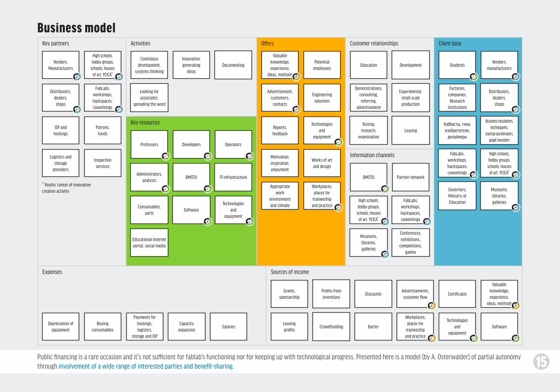
15Public financing is a rare occasion and it's not sufficient for fablab's functioning nor for keeping up with technological progress. Presented here is a model (by A. Osterwalder) of partial autonomy through involvement of a wide range of interested parties and benefit-sharing.
Key partners Activities Offers Customer relationships Client base
Key resources
Information channels
Expenses Sources of income
Business model
Inspectionservices
Patrons,funds
Documenting
Looking forassociates,
spreading the word
Valuableknowledge,experience,
ideas, methods
Valuableknowledge,experience,
ideas, methods
Advertisement,customers,
contacts
Advertisements,customer flow
Demonstrations,consulting,referring,
advertisement
Development
Testing,research,
examination
Education Students
Factories,companies,Research
institutions
Governors,Ministry ofEducation
Leasing
Continiousdevelopment,
systems thinking
Professors Developers Operators
Technologiesand
equipment
Technologiesand
equipment
Technologiesand
equipment
Potentialemployees
Works of artand design
Appropriatework
environmentand climate
Motivation,inspiration,enjoyment
Reports,feedback
Workplaces,places for
traineeshipand practice
Engineeringsolutions
Experimental,small scaleproduction
Software
Software
Consumables,parts
Capacityexpancion
Depreciation ofequipment
Payments forhostings,logistics,
storage and ISP
SalariesBuying
consumables
IT-infrastructureBMSTU BMSTU
Conferences,exhibitions,
competitions,games
Museums,libraries,galleries
Museums,libraries,galleries
Crowdfunding
Educational internet portal, social media
FabLabs,workshops,hackspaces,coworkings
Partner networkAdministrators,
analysts
Innovation,generating
ideas
Vendors,Manufacturers
Vendors,manufacturers
Хоббисты, гики, изобретатели,
дизайнеры
Distributors,dealers,shops
Distributors,dealers,shops
FabLabs,workshops,hackspaces,coworkings
FabLabs,workshops,hackspaces,coworkings
High schools,hobby groups,
schools, houses of art, YCICA*
High schools,hobby groups,
schools, houses of art, YCICA*
High schools,hobby groups,
schools, houses of art, YCICA*
Business incubators,technoparks,
startup-accelerators,angel investors
ISP andhostings
Logistics andstorage
providers
Grants,sponsorship
Discounts
Leasingprofits
Profits frominventions
Barter
Certificates
Workplaces,places for
traineeshipand practice
A
A
I I
I
I
I J J
K
K
L
L
L
B
B
C
C
DD
EE
F
F
F
G
G
G
H
H
* Youths’ center of innovativecreative activity
16
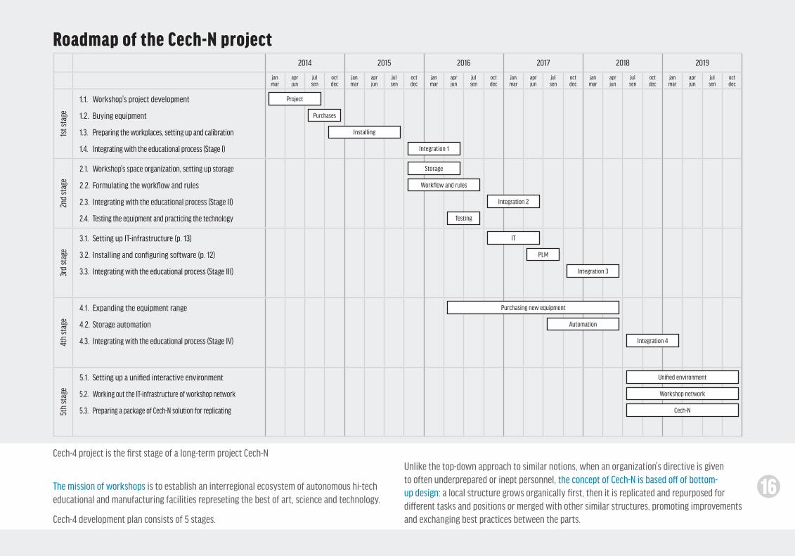
Cech-4 project is the first stage of a long-term project Cech-N
The mission of workshops is to establish an interregional ecosystem of autonomous hi-tech educational and manufacturing facilities represeting the best of art, science and technology.
Cech-4 development plan consists of 5 stages.
Roadmap of the Cech-N project
Unlike the top-down approach to similar notions, when an organization's directive is given to often underprepared or inept personnel, the concept of Cech-N is based off of bottom-up design: a local structure grows organically first, then it is replicated and repurposed for different tasks and positions or merged with other similar structures, promoting improvements and exchanging best practices between the parts.
2014 2015 2016 2017 2018 2019
janmar
aprjun
julsen
oct dec
janmar
aprjun
julsen
oct dec
janmar
aprjun
julsen
oct dec
janmar
aprjun
julsen
oct dec
janmar
aprjun
julsen
oct dec
janmar
aprjun
julsen
oct dec
1st s
tage
1.1. Workshop's project development
1.2. Buying equipment
1.3. Preparing the workplaces, setting up and calibration
1.4. Integrating with the educational process (Stage I)
2nd
stag
e
2.1. Workshop's space organization, setting up storage
2.2. Formulating the workflow and rules
2.3. Integrating with the educational process (Stage II)
2.4. Testing the equipment and practicing the technology
3rd
stag
e
3.1. Setting up IT-infrastructure (p. 13)
3.2. Installing and configuring software (p. 12)
3.3. Integrating with the educational process (Stage III)
4th
stag
e
4.1. Expanding the equipment range
4.2. Storage automation
4.3. Integrating with the educational process (Stage IV)
5th
stag
e
5.1. Setting up a unified interactive environment
5.2. Working out the IT-infrastructure of workshop network
5.3. Preparing a package of Cech-N solution for replicating
Project
Purchases
Installing
Integration 1
Integration 2
Integration 3
Integration 4
Storage
Workflow and rules
Testing
IT
PLM
Purchasing new equipment
Automation
Unified environment
Cech-N
Workshop network
16
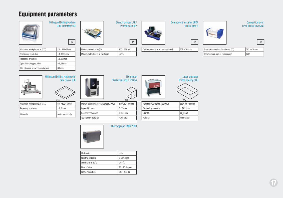
17
Equipment parametersMilling and Drilling Machine
LPKF ProtoMat s103
Milling and Drilling Machine vhf CAM Classic 200
Stencil printer LPKF ProtoPlace S RP
3D-printer Stratasys Fortus 250ms
Thermograph IRTIS 2000
Component Installer LPKF ProtoPlace S
Laser engraverTrotec Speedy-300
Convection ovenLPKF ProtoFlow S/N2
Maximum workpiece size (XYZ) 229 × 305 × 22 mm
Positioning resolution ± 0,0005 mm
Repeating precision ± 0,001 mm
Optical binding precision ± 0,02 mm
Min. distance between conductors 0,1 mm
Maximum workpiece size (XYZ) 650 × 400 × 200 mm
Positioning accuracy ± 0,025 mm
Emitter CO2 85 W
Material nonmetalы
The maximum size of the board (XY) 297 × 420 mm
The minimum size of components 0201
Maximum workpiece size (XYZ) 500 × 500 × 60 mm
Repeating precision ± 0,01 mm
Materials nonferrous metals
Maксимальный рабочая область (XYZ) 250 × 250 × 300 mm
Layer thickness 0,178 mm
Geometry deviation ± 0,25 mm
Technology, material FDM, ABS
IR-detector InSb
Spectral response 3–5 microns
Sensitivity at 30 °С 0,05 °C
Field of view 25 × 20 degrees
Frame resolution 640 × 480 dpi
The maximum size of the board (XY) 230 × 305 mmMaximum work area (XY) 300 × 300 mm
Maximum thickness of the board 5 mm
XYZXYZXYZ
XY XY XY XY

18
Contacts
Daler Iskandarovich ArabovLead developerHead of the workshop
Andrey Igorevich VlasovProject supervisorDeputy Head of Department of ScienceLaureate of the State Prize of Russian Federation for Science and TechnologyAssociate professor, Ph. D
Vadim Anatolievich ShahnovHead of the Department IU4Corresponding Member of the Russian Academy of SciencesHonored Worker of ScienceAssociate Professor of Technical Sciences,Laureate of the USSR State Prize,Prize of the USSR Council of Ministers,Prize of the Russian Federation Council of MinistersFull member of the Academy of Science in Electrical Engineering,International Telecommunications Academy andInternational Informatization Academy
+7 (916) [email protected]@gmail.comvk.com/chudodeyfb.com/daler.arabov
+7 (903) [email protected]
+7 (499) 263-65-52
Partners
Recommended