Siemens D 31 · 2012
99/2 Introduction 9/2 Application9/2 More information
9/3 SINAMICS S110 servo drives9/3 Overview9/4 Function9/6 Configuration9/7 Technical specifications9/8 More information
9/9 CU305 Control Unit 9/9 Overview9/9 Design9/9 Integration9/11 Technical specifications9/11 Selection and ordering data
9/12 PM340 Power Modules in blocksize format
9/12 Overview9/12 Integration9/15 Technical specifications9/21 Selection and ordering data9/21 Accessories9/22 Characteristic curves
9/24 Line-side components9/24 Line reactors9/28 Line filter9/29 Recommended line-side
power components
9/31 DC link components9/31 Braking resistors
9/33 Load-side power components9/33 Motor reactors
9/36 Supplementary system components9/36 BOP20 Basic Operator Panel 9/37 Ingelligent Operator Panel IOP9/38 Safe Brake Relay
9/39 Encoder system connection9/40 SMC10 Sensor Module Cabinet-Mounted 9/41 SMC20 Sensor Module Cabinet-Mounted 9/42 SMC30 Sensor Module Cabinet-Mounted
SINAMICS S110servo drives0.12 kW to 90 kW (0.16 hp to 125 hp)
© Siemens AG 2011
SINAMICS S110 servo drives0.12 kW to 90 kW (0.16 hp to 125 hp)
Introduction
9/2 Siemens D 31 · 2012
9
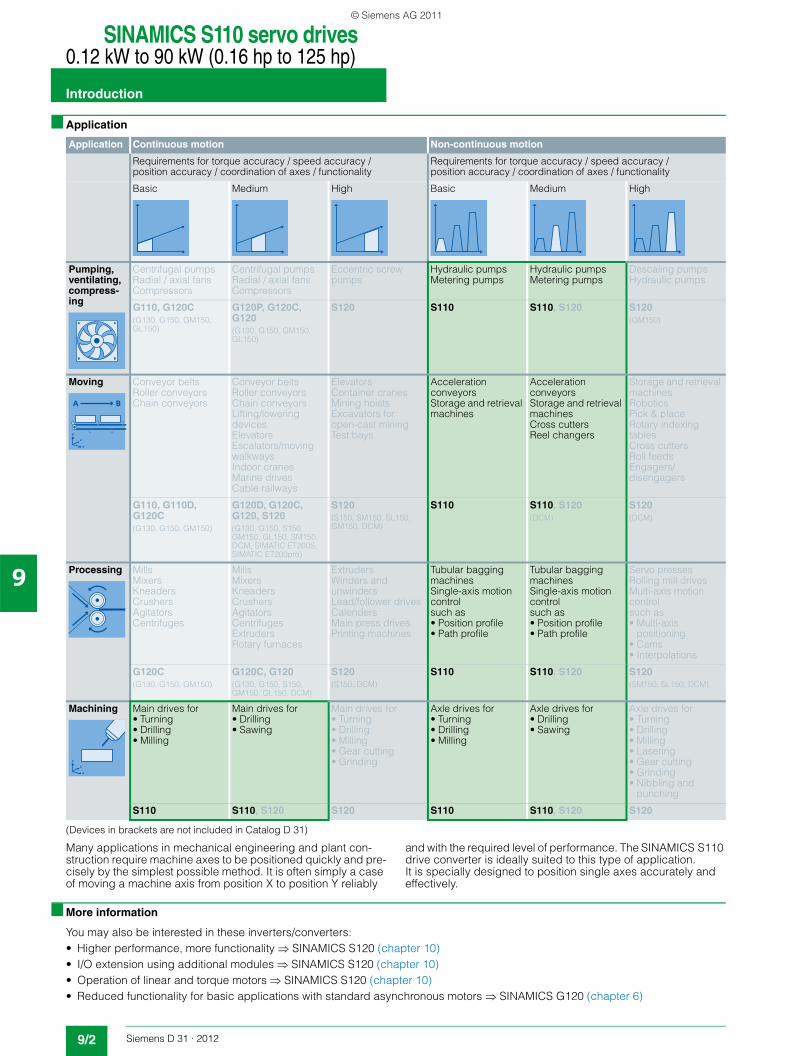
■ Application
(Devices in brackets are not included in Catalog D 31)
Many applications in mechanical engineering and plant con-struction require machine axes to be positioned quickly and pre-cisely by the simplest possible method. It is often simply a case of moving a machine axis from position X to position Y reliably
and with the required level of performance. The SINAMICS S110 drive converter is ideally suited to this type of application. It is specially designed to position single axes accurately and effectively.
■ More information
You may also be interested in these inverters/converters:• Higher performance, more functionality SINAMICS S120 (chapter 10)• I/O extension using additional modules SINAMICS S120 (chapter 10)• Operation of linear and torque motors SINAMICS S120 (chapter 10)• Reduced functionality for basic applications with standard asynchronous motors SINAMICS G120 (chapter 6)
Application Continuous motion Non-continuous motion
Requirements for torque accuracy / speed accuracy / position accuracy / coordination of axes / functionality
Requirements for torque accuracy / speed accuracy / position accuracy / coordination of axes / functionality
Basic
Medium
High
Basic
Medium
High
Pumping, ventilating, compress-ing
Centrifugal pumpsRadial / axial fansCompressors
Centrifugal pumpsRadial / axial fansCompressors
Eccentric screw pumps
Hydraulic pumps Metering pumps
Hydraulic pumps Metering pumps
Descaling pumpsHydraulic pumps
G110, G120C(G130, G150, GM150, GL150)
G120P, G120C, G120(G130, G150, GM150, GL150)
S120 S110 S110, S120 S120(GM150)
Moving
Conveyor beltsRoller conveyorsChain conveyors
Conveyor beltsRoller conveyorsChain conveyorsLifting/lowering devicesElevatorsEscalators/moving walkwaysIndoor cranesMarine drivesCable railways
ElevatorsContainer cranesMining hoistsExcavators for open-cast miningTest bays
Acceleration conveyors Storage and retrieval machines
Acceleration conveyors Storage and retrieval machines Cross cutters Reel changers
Storage and retrieval machinesRoboticsPick & placeRotary indexing tablesCross cuttersRoll feedsEngagers/disengagers
G110, G110D, G120C(G130, G150, GM150)
G120D, G120C, G120, S120(G130, G150, S150, GM150, GL150, SM150, DCM, SIMATIC ET200S, SIMATIC ET200pro)
S120(S150, SM150, SL150, GM150, DCM)
S110 S110, S120(DCM)
S120(DCM)
Processing
MillsMixersKneadersCrushersAgitatorsCentrifuges
MillsMixersKneadersCrushersAgitatorsCentrifugesExtrudersRotary furnaces
ExtrudersWinders and unwindersLead/follower drivesCalendersMain press drivesPrinting machines
Tubular bagging machines Single-axis motion control such as • Position profile • Path profile
Tubular bagging machines Single-axis motion control such as • Position profile • Path profile
Servo pressesRolling mill drivesMulti-axis motion controlsuch as• Multi-axis
positioning• Cams• Interpolations
G120C(G130, G150, GM150)
G120C, G120(G130, G150, S150, GM150, GL150, DCM)
S120(S150, DCM)
S110 S110, S120 S120(SM150, SL150, DCM)
Machining
Main drives for • Turning • Drilling • Milling
Main drives for • Drilling • Sawing
Main drives for • Turning• Drilling• Milling• Gear cutting• Grinding
Axle drives for • Turning • Drilling • Milling
Axle drives for • Drilling • Sawing
Axle drives for• Turning• Drilling• Milling• Lasering• Gear cutting• Grinding• Nibbling and
punching
S110 S110, S120 S120 S110 S110, S120 S120
© Siemens AG 2011
SINAMICS S110 servo drives0.12 kW to 90 kW (0.16 hp to 125 hp)
SINAMICS S110 servo drives
9/3Siemens D 31 · 2012
9
■ Overview
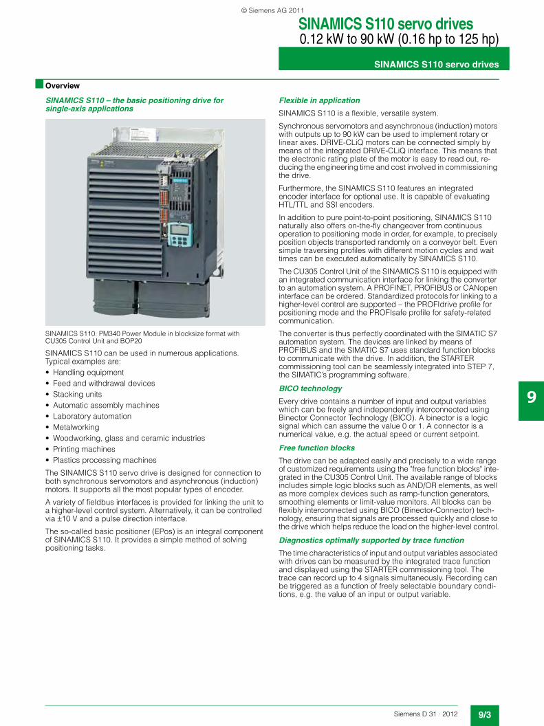
SINAMICS S110 – the basic positioning drive for single-axis applications
SINAMICS S110: PM340 Power Module in blocksize format with CU305 Control Unit and BOP20
SINAMICS S110 can be used in numerous applications. Typical examples are:• Handling equipment• Feed and withdrawal devices• Stacking units• Automatic assembly machines• Laboratory automation• Metalworking• Woodworking, glass and ceramic industries• Printing machines• Plastics processing machines
The SINAMICS S110 servo drive is designed for connection to both synchronous servomotors and asynchronous (induction) motors. It supports all the most popular types of encoder.
A variety of fieldbus interfaces is provided for linking the unit to a higher-level control system. Alternatively, it can be controlled via ±10 V and a pulse direction interface.
The so-called basic positioner (EPos) is an integral component of SINAMICS S110. It provides a simple method of solving positioning tasks.
Flexible in application
SINAMICS S110 is a flexible, versatile system.
Synchronous servomotors and asynchronous (induction) motors with outputs up to 90 kW can be used to implement rotary or linear axes. DRIVE-CLiQ motors can be connected simply by means of the integrated DRIVE-CLiQ interface. This means that the electronic rating plate of the motor is easy to read out, re-ducing the engineering time and cost involved in commissioning the drive.
Furthermore, the SINAMICS S110 features an integrated encoder interface for optional use. It is capable of evaluating HTL/TTL and SSI encoders.
In addition to pure point-to-point positioning, SINAMICS S110 naturally also offers on-the-fly changeover from continuous operation to positioning mode in order, for example, to precisely position objects transported randomly on a conveyor belt. Even simple traversing profiles with different motion cycles and wait times can be executed automatically by SINAMICS S110.
The CU305 Control Unit of the SINAMICS S110 is equipped with an integrated communication interface for linking the converter to an automation system. A PROFINET, PROFIBUS or CANopen interface can be ordered. Standardized protocols for linking to a higher-level control are supported – the PROFIdrive profile for positioning mode and the PROFIsafe profile for safety-related communication.
The converter is thus perfectly coordinated with the SIMATIC S7 automation system. The devices are linked by means of PROFIBUS and the SIMATIC S7 uses standard function blocks to communicate with the drive. In addition, the STARTER commissioning tool can be seamlessly integrated into STEP 7, the SIMATIC’s programming software.
BICO technology
Every drive contains a number of input and output variables which can be freely and independently interconnected using Binector Connector Technology (BICO). A binector is a logic signal which can assume the value 0 or 1. A connector is a numerical value, e.g. the actual speed or current setpoint.
Free function blocks
The drive can be adapted easily and precisely to a wide range of customized requirements using the "free function blocks" inte-grated in the CU305 Control Unit. The available range of blocks includes simple logic blocks such as AND/OR elements, as well as more complex devices such as ramp-function generators, smoothing elements or limit-value monitors. All blocks can be flexibly interconnected using BICO (Binector-Connector) tech-nology, ensuring that signals are processed quickly and close to the drive which helps reduce the load on the higher-level control.
Diagnostics optimally supported by trace function
The time characteristics of input and output variables associated with drives can be measured by the integrated trace function and displayed using the STARTER commissioning tool. The trace can record up to 4 signals simultaneously. Recording can be triggered as a function of freely selectable boundary condi-tions, e.g. the value of an input or output variable.
© Siemens AG 2011

SINAMICS S110 servo drives0.12 kW to 90 kW (0.16 hp to 125 hp)
SINAMICS S110 servo drives
9/4 Siemens D 31 · 2012
9
■ Overview
Safety Integrated
The integrated safety functions of SINAMICS S110 provide highly effective application-oriented protection for personnel and machinery (terms as defined in IEC 61800-5-2).
The following Safety Integrated Basic Functions are included as standard:• Safe Torque Off (STO)• Safe Brake Control (SBC)• Safe Stop 1 (SS1)
The following Safety Integrated Extended Functions are optionally available:• Safe Stop 2 (SS2)• Safe Operating Stop (SOS)• Safely Limited Speed (SLS)• Safe Speed Monitor (SSM)• Safe Direction (SDI)
The Safety Integrated functions are fully integrated into the drive system. They can be activated via fail-safe digital inputs on the CU305 Control Unit or via PROFINET or PROFIBUS with PROFIsafe.
The Safety Integrated functions are implemented electronically and therefore offer short response times in comparison to solutions with externally implemented monitoring functions.
Additional information is provided in chapter Highlights, section Safety Integrated.
Accessories
Memory cards
The memory card can be used as an option for SINAMICS S110. The relevant slot is located underneath the CU305 Control Unit. The complete functionality of SINAMICS S110 can be saved on the memory card: the parameter settings and the firmware. When service is required, e.g. after the converter has been replaced and the data has been downloaded from the memory card, the drive system is immediately ready for use once more.
A SINAMICS Micro Memory Card (MMC) is essential, if the optional Safety Integrated Extended Functions are used. The necessary license is saved on the MMC.
Intelligent Operator Panel (IOP)
The IOP supports both entry-level personnel and drive experts. Thanks to the large plain text display, menu-based operation and application wizards, it is easy to commission, diagnose and locally control standard drives.
The IOP can be connected to the RS232 interface of the CU305 Control Unit using the appropriate connecting cable. Mounting the IOP directly on the CU305 Control Unit is not possible.
Varnished modules
The following units are equipped as standard with varnished or partially varnished modules:• Blocksize format units• Control Units• Sensor Modules
The varnish coating protects the sensitive SMD components against corrosive gases, chemically active dust and moisture.
■ Function
SINAMICS S110 – Summary of the most important functions
Control method Servo control
• Asynchronous (induction) motor
Torque control with encoderSpeed control with and without encoderPosition control with encoder
• Synchronous motor Torque control with encoderSpeed control with encoderPosition control with encoder
Control function V/f characteristic
• Asynchronous (induction) motor
Basic linear
• Synchronous motor –
Basic positioner (EPos) Absolute and relative positioningLinear and rotary axisMotor encoder or direct measuring system4 referencing modes16 traversing blocksDirect setpoint input (MDI)Jog modeBacklash compensationFollowing error monitoringCam signalsPosition tracking for extended position range....
Safety Integrated Safe Torque OFF (STO)Safe Brake Control (SBC)Safe Stop 1 (SS1)Safe Stop 2 (SS2)Safe Operating Stop (SOS)Safely Limited Speed (SLS)Safe Speed Monitor (SSM)Safe Direction (SDI)
Protection functions Undervoltage DC link voltageOvervoltage DC link voltageOvercurrent power unitOvercurrent motorOverload power unit (I²t)Short-circuitGround faultOvertemperature motorOvertemperature power unit
Functions for simplified commissioning
Electronic rating plate for motors with DRIVE-CLiQMotor data identificationPole position identificationAutomatic controller optimization with STARTER
Free function blocks Logic and arithmetic blocks
Data sets 2 command data sets2 drive data sets2 motor data sets1 encoder data set
Further software functions
BICO interconnectionTechnology controller (PID)Extended setpoint channelAutomatic restartArmature short-circuit brakeDC brakeBrake controlVdc_min control (kinetic buffering)Vdc_max controlTravel to fixed stopVertical axisVariable signaling functionsCentral measuring probe evaluationPulse direction interfaceEfficiency optimization for asynchronous (induction) motorsRuntime (operating hours counter)
© Siemens AG 2011

SINAMICS S110 servo drives0.12 kW to 90 kW (0.16 hp to 125 hp)
SINAMICS S110 servo drives
9/5Siemens D 31 · 2012
9
■ Function
Basic positioner (EPos)
SINAMICS S110 provides powerful and precise positioning functions. Due to its flexibility and adaptability, the basic positioner can be used for a wide range of positioning tasks.
The functions are easy to handle both during commissioning and during operation. Furthermore, they are characterized by their comprehensive monitoring functions.
Many applications can be carried out without external position controllers.
The EPos basic positioner is available as a function module that can be activated in the drive, and is used for the absolute/relative positioning of linear and rotary axes (modulo) with both rotary and linear motor encoders (indirect measuring system).
User-friendly configuring and commissioning including control panel (operation using PC) and diagnostics with the STARTER commissioning tool.
In addition to extremely flexible positioning functions, EPos offers a high degree of user-friendliness and reliability thanks to integral monitoring and compensation functions.
Different operating modes and their functionality increase flexibility and plant productivity, for example, by means of "on-the-fly" and bumpless correction of the motion control.
Preconfigured PROFIdrive positioning frames are available which, when selected, automatically establish the internal "connection" to the basic positioner.
Functionality of the EPos basic positioner
Closed-loop position control with the following essential components• Position actual value sensing (including the lower-level
measuring probe evaluation and reference mark search)• Position controller (including limits, adaptation and pre-control
calculation)• Monitoring functions (standstill, positioning and dynamic
following error monitoring, cam signals)
Mechanical system• Backlash compensation• Modulo offset
Limits• Speed/acceleration/delay/jerk limitation• Software limit switch (traversing range limitation by means of
position setpoint evaluation)• Stop cams (traversing range limitation by means of hardware
limit switch evaluation)
Referencing and alignment• Set reference point (for an axis at standstill)• Search for reference (separate mode including reversing cam
functionality, automatic reversal of direction, referencing to "output cam and encoder zero mark" or only "encoder zero mark" or "external zero mark (BERO)")
• Flying referencing (seamless subordinate referencing is pos-sible during "normal" traversing with the aid of measuring input evaluation, generally evaluation, e.g. of a proximity sensor). Subordinate function for the modes "jog", "direct setpoint input/MDI" and "traversing blocks")
• Absolute encoder alignment
Traversing blocks mode (16 traversing blocks)• Positioning using traversing blocks stored in the drive unit,
including block change enable conditions and specific tasks for a previously referenced axis
• Traversing block editor using STARTER• A traversing block contains the following information:
- Job number and job (e.g. positioning, waiting, GOTO set jump, setting of binary outputs, travel to fixed stop)
- Motion parameters (target position, override speed for acceleration and deceleration)
- Mode (e.g.: hide block, continuation conditions such as "Continue_with_stop", "Continue_flying" and "Continue_externally using high-speed probe inputs")
- Job parameters (e.g. wait time, block step conditions)
Direct setpoint input (MDI) mode• Positioning (absolute, relative) and setting-up (endless
closed-loop position control) using direct setpoint inputs (e.g. via the PLC using process data)
• It is always possible to influence the motion parameters during traversing (on-the-fly setpoint acceptance) as well as for on-the-fly changes between the setup and positioning modes
• The direct setpoint specification operating mode (MDI) can also be used in the relative positioning or setup mode if the axis is not referenced. This means that on-the-fly synchroniza-tion and re-referencing can be carried out using "flying refer-encing".
Jog mode• Closed-loop position controlled traversing of the axis with
"endless position controlled" or "jog incremental" modes (traverse through a "step width"), which can be toggled
© Siemens AG 2011
SINAMICS S110 servo drives0.12 kW to 90 kW (0.16 hp to 125 hp)
SINAMICS S110 servo drives
9/6 Siemens D 31 · 2012
9
■ Configuration
The following electronic configuring aids and engineering tools are available for the SINAMICS S110 servo drives:
Selection guide DT Configurator within the CA 01
The interactive catalog CA 01 – the offline mall of Siemens Industry Automation & Drive Technologies – contains over 100000 products with approximately 5 million possible drive system product variants. The DT Configurator has been devel-oped to facilitate selection of the optimum motor and/or inverter from the wide spectrum of drives. The configurator is integrated as a "selection guide" in this catalog on the DVD-ROM with the selection and configuration tools.
Online DT Configurator
In addition, the DT Configurator can be used in the Internet without requiring any installation. The DT Configurator can be found in the Siemens Industry Mall at the following address:www.siemens.com/dt-configurator
SIZER for Siemens Drives engineering tool
The SIZER for Siemens Drives engineering tool makes it easy to engineer the SINAMICS and MICROMASTER 4 drive families. It provides support when selecting the hardware and firmware components necessary to implement a drive task. SIZER for Siemens Drives covers the full range of operations required to configure a complete drive system, from basic single drives to demanding multi-axis applications.
Additional information on the SIZER for Siemens Drives engineering tool is provided in the chapter Engineering tools.
STARTER commissioning tool
The STARTER commissioning tool allows menu-prompted commissioning, optimization and diagnostics. In addition to SINAMICS drives, STARTER is also suitable for MICROMASTER 4 units and the frequency converters for the distributed I/O SIMATIC ET 200S FC and SIMATIC ET 200pro FC.
Additional information on the STARTER commissioning tool is provided in the chapter Engineering tools.
Drive ES engineering system
Drive ES is the engineering system that can be used to integrate the communication, configuration and data management of Sie-mens drive technology into the SIMATIC automation world easily, efficiently and cost-effectively. The STEP 7 Manager user inter-face provides the ideal basis for this. A variety of software pack-ages are available for SINAMICS – Drive ES Basic, Drive ES SIMATIC and Drive ES PCS 7.1.
Additional information on the Drive ES engineering system is provided in the chapter Engineering tools.
© Siemens AG 2011
SINAMICS S110 servo drives0.12 kW to 90 kW (0.16 hp to 125 hp)
SINAMICS S110 servo drives
9/7Siemens D 31 · 2012
9
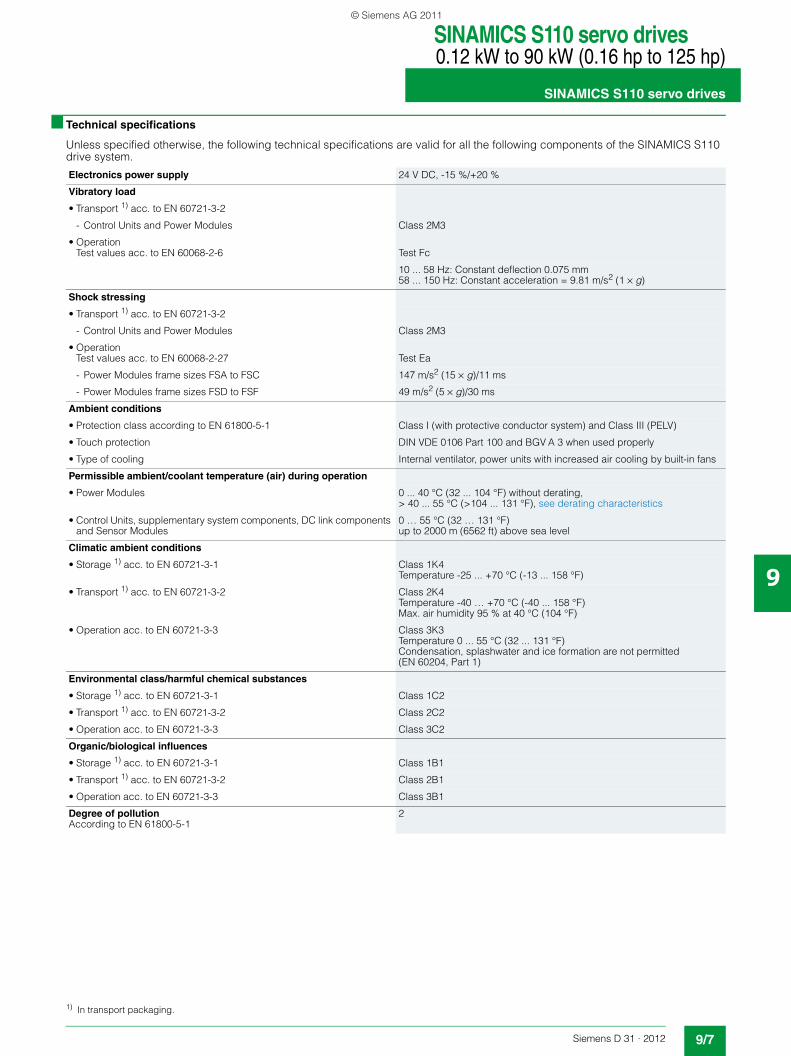
■ Technical specifications
Unless specified otherwise, the following technical specifications are valid for all the following components of the SINAMICS S110 drive system.
Electronics power supply 24 V DC, -15 %/+20 %
Vibratory load
• Transport 1) acc. to EN 60721-3-2
- Control Units and Power Modules Class 2M3
• OperationTest values acc. to EN 60068-2-6 Test Fc
10 ... 58 Hz: Constant deflection 0.075 mm58 ... 150 Hz: Constant acceleration = 9.81 m/s2 (1 × g)
Shock stressing
• Transport 1) acc. to EN 60721-3-2
- Control Units and Power Modules Class 2M3
• OperationTest values acc. to EN 60068-2-27 Test Ea
- Power Modules frame sizes FSA to FSC 147 m/s2 (15 × g)/11 ms
- Power Modules frame sizes FSD to FSF 49 m/s2 (5 × g)/30 ms
Ambient conditions
• Protection class according to EN 61800-5-1 Class I (with protective conductor system) and Class III (PELV)
• Touch protection DIN VDE 0106 Part 100 and BGV A 3 when used properly
• Type of cooling Internal ventilator, power units with increased air cooling by built-in fans
Permissible ambient/coolant temperature (air) during operation
• Power Modules 0 ... 40 °C (32 ... 104 °F) without derating,> 40 ... 55 °C (>104 ... 131 °F), see derating characteristics
• Control Units, supplementary system components, DC link components and Sensor Modules
0 … 55 °C (32 … 131 °F)up to 2000 m (6562 ft) above sea level
Climatic ambient conditions
• Storage 1) acc. to EN 60721-3-1 Class 1K4Temperature -25 ... +70 °C (-13 ... 158 °F)
• Transport 1) acc. to EN 60721-3-2 Class 2K4Temperature -40 … +70 °C (-40 ... 158 °F)Max. air humidity 95 % at 40 °C (104 °F)
• Operation acc. to EN 60721-3-3 Class 3K3Temperature 0 ... 55 °C (32 ... 131 °F)Condensation, splashwater and ice formation are not permitted (EN 60204, Part 1)
Environmental class/harmful chemical substances
• Storage 1) acc. to EN 60721-3-1 Class 1C2
• Transport 1) acc. to EN 60721-3-2 Class 2C2
• Operation acc. to EN 60721-3-3 Class 3C2
Organic/biological influences
• Storage 1) acc. to EN 60721-3-1 Class 1B1
• Transport 1) acc. to EN 60721-3-2 Class 2B1
• Operation acc. to EN 60721-3-3 Class 3B1
Degree of pollutionAccording to EN 61800-5-1
2
1) In transport packaging.
© Siemens AG 2011
SINAMICS S110 servo drives0.12 kW to 90 kW (0.16 hp to 125 hp)
SINAMICS S110 servo drives
9/8 Siemens D 31 · 2012
9
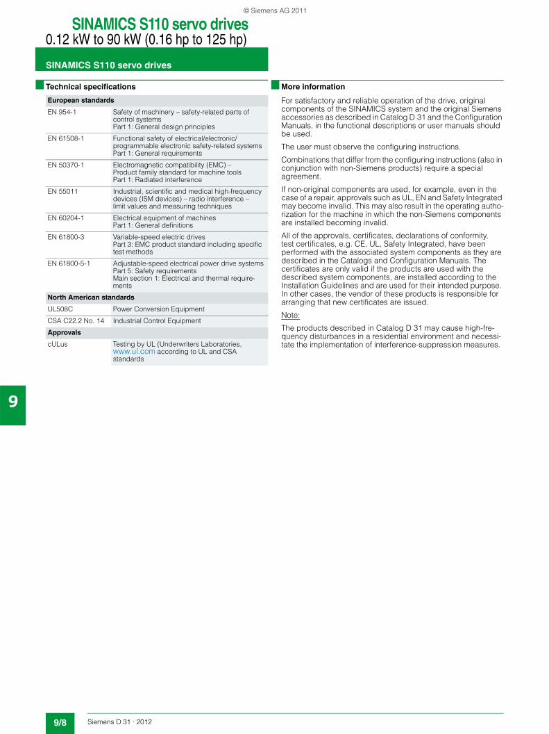
■ Technical specifications ■ More information
For satisfactory and reliable operation of the drive, original components of the SINAMICS system and the original Siemens accessories as described in Catalog D 31 and the Configuration Manuals, in the functional descriptions or user manuals should be used.
The user must observe the configuring instructions.
Combinations that differ from the configuring instructions (also in conjunction with non-Siemens products) require a special agreement.
If non-original components are used, for example, even in the case of a repair, approvals such as UL, EN and Safety Integrated may become invalid. This may also result in the operating autho-rization for the machine in which the non-Siemens components are installed becoming invalid.
All of the approvals, certificates, declarations of conformity, test certificates, e.g. CE, UL, Safety Integrated, have been performed with the associated system components as they are described in the Catalogs and Configuration Manuals. The certificates are only valid if the products are used with the described system components, are installed according to the Installation Guidelines and are used for their intended purpose. In other cases, the vendor of these products is responsible for arranging that new certificates are issued.
Note:
The products described in Catalog D 31 may cause high-fre-quency disturbances in a residential environment and necessi-tate the implementation of interference-suppression measures.
European standards
EN 954-1 Safety of machinery – safety-related parts of control systems Part 1: General design principles
EN 61508-1 Functional safety of electrical/electronic/programmable electronic safety-related systemsPart 1: General requirements
EN 50370-1 Electromagnetic compatibility (EMC) –Product family standard for machine tools Part 1: Radiated interference
EN 55011 Industrial, scientific and medical high-frequency devices (ISM devices) – radio interference – limit values and measuring techniques
EN 60204-1 Electrical equipment of machinesPart 1: General definitions
EN 61800-3 Variable-speed electric drives Part 3: EMC product standard including specific test methods
EN 61800-5-1 Adjustable-speed electrical power drive systemsPart 5: Safety requirementsMain section 1: Electrical and thermal require-ments
North American standards
UL508C Power Conversion Equipment
CSA C22.2 No. 14 Industrial Control Equipment
Approvals
cULus Testing by UL (Underwriters Laboratories, www.ul.com according to UL and CSA standards
© Siemens AG 2011
SINAMICS S110 servo drives0.12 kW to 90 kW (0.16 hp to 125 hp)
CU305 Control Unit
9/9Siemens D 31 · 2012
9
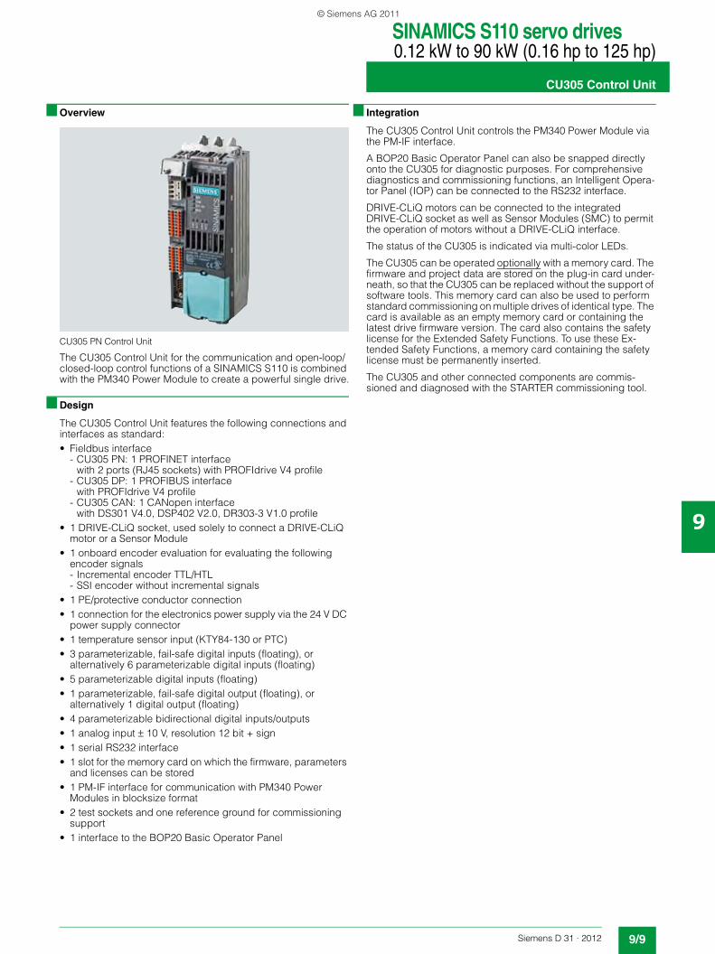
■ Overview
CU305 PN Control Unit
The CU305 Control Unit for the communication and open-loop/closed-loop control functions of a SINAMICS S110 is combined with the PM340 Power Module to create a powerful single drive.
■ Design
The CU305 Control Unit features the following connections and interfaces as standard:• Fieldbus interface
- CU305 PN: 1 PROFINET interface with 2 ports (RJ45 sockets) with PROFIdrive V4 profile
- CU305 DP: 1 PROFIBUS interface with PROFIdrive V4 profile
- CU305 CAN: 1 CANopen interface with DS301 V4.0, DSP402 V2.0, DR303-3 V1.0 profile
• 1 DRIVE-CLiQ socket, used solely to connect a DRIVE-CLiQ motor or a Sensor Module
• 1 onboard encoder evaluation for evaluating the following encoder signals - Incremental encoder TTL/HTL- SSI encoder without incremental signals
• 1 PE/protective conductor connection• 1 connection for the electronics power supply via the 24 V DC
power supply connector• 1 temperature sensor input (KTY84-130 or PTC)• 3 parameterizable, fail-safe digital inputs (floating), or
alternatively 6 parameterizable digital inputs (floating)• 5 parameterizable digital inputs (floating)• 1 parameterizable, fail-safe digital output (floating), or
alternatively 1 digital output (floating)• 4 parameterizable bidirectional digital inputs/outputs• 1 analog input ± 10 V, resolution 12 bit + sign• 1 serial RS232 interface• 1 slot for the memory card on which the firmware, parameters
and licenses can be stored• 1 PM-IF interface for communication with PM340 Power
Modules in blocksize format• 2 test sockets and one reference ground for commissioning
support• 1 interface to the BOP20 Basic Operator Panel
■ Integration
The CU305 Control Unit controls the PM340 Power Module via the PM-IF interface.
A BOP20 Basic Operator Panel can also be snapped directly onto the CU305 for diagnostic purposes. For comprehensive diagnostics and commissioning functions, an Intelligent Opera-tor Panel (IOP) can be connected to the RS232 interface.
DRIVE-CLiQ motors can be connected to the integrated DRIVE-CLiQ socket as well as Sensor Modules (SMC) to permit the operation of motors without a DRIVE-CLiQ interface.
The status of the CU305 is indicated via multi-color LEDs.
The CU305 can be operated optionally with a memory card. The firmware and project data are stored on the plug-in card under-neath, so that the CU305 can be replaced without the support of software tools. This memory card can also be used to perform standard commissioning on multiple drives of identical type. The card is available as an empty memory card or containing the latest drive firmware version. The card also contains the safety license for the Extended Safety Functions. To use these Ex-tended Safety Functions, a memory card containing the safety license must be permanently inserted.
The CU305 and other connected components are commis-sioned and diagnosed with the STARTER commissioning tool.
© Siemens AG 2011
SINAMICS S110 servo drives0.12 kW to 90 kW (0.16 hp to 125 hp)
CU305 Control Unit
9/10 Siemens D 31 · 2012
9
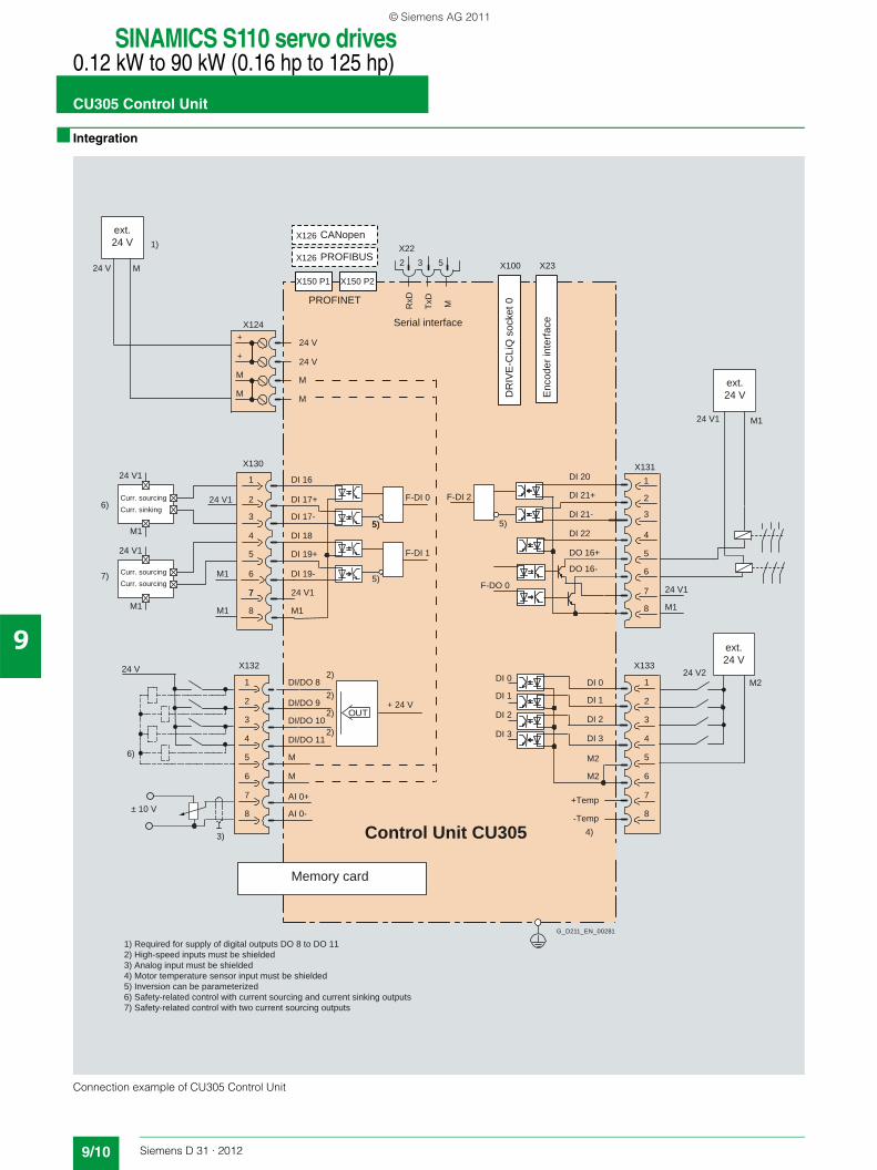
■ Integration
Connection example of CU305 Control Unit
24 V
24 V
24 V2
24 V1
24 V1
Curr. sinking
Curr. sourcingCurr. sourcing
Curr. sourcing
+ 24 V
24 V1
Memory card
Enc
oder
inte
rfaceSerial interface
DR
IVE
-CLi
Q s
ocke
t 0
24 Vext.
24 Vext.
24 Vext.
7) Safety-related control with two current sourcing outputs6) Safety-related control with current sourcing and current sinking outputs5) Inversion can be parameterized4) Motor temperature sensor input must be shielded3) Analog input must be shielded2) High-speed inputs must be shielded1) Required for supply of digital outputs DO 8 to DO 11
7
24 V
24 V
G_D211_EN_00281
PROFINET
M1
± 10 V
3)
OUT
X130
4
X131
6
532 X23
X132 X133
Control Unit CU305
X100
X150 P2X150 P1
X126 PROFIBUS
X126 CANopen
RxD
TxD
M
M1
M1
24 V1
M2
X22
M
M
X124
M
+
M
+
M
M1
24 V1
DI 19+
DI 19-
M1
M1
DI 18
DI 17-
DI 17+
DI 16
F-DI 0
F-DO 0
F-DI 2
5)
F-DI 1
4
7
3
2
1
5
6
8
DI/DO 11
DI/DO 10
DI/DO 9
DI/DO 8
M
M
AI 0+
AI 0-
4
7
3
2
1
5
6
8-Temp
+Temp
M2
M2
DI 0
DI 3
DI 2
DI 1DI 0
DI 3
DI 2
DI 1
6)
4)
5)
2)
2)
2)
2)
1)
5)
5)
M1
24 V1
DO 16-
DO 16+
DI 22
DI 21-
DI 21+
DI 20
5
4
3
2
1
7
8
3
2
1
6)
7)
5
6
8
7
© Siemens AG 2011
SINAMICS S110 servo drives0.12 kW to 90 kW (0.16 hp to 125 hp)
CU305 Control Unit
9/11Siemens D 31 · 2012
9
■ Technical specifications
■ Selection and ordering data
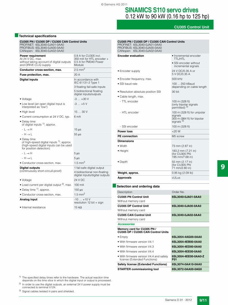
CU305 PN / CU305 DP / CU305 CAN Control UnitsPROFINET: 6SL3040-0JA01-0AA0PROFIBUS: 6SL3040-0JA00-0AA0CANopen: 6SL3040-0JA02-0AA0
Power requirementAt 24 V DC, max.without taking account of digital outputs and DRIVE-CLiQ supply
0.8 A for CU305 incl. 350 mA for HTL encoder + 0.5 A for PM340 Power Module
Conductor cross-section, max. 2.5 mm2
Fuse protection, max. 20 A
Digital inputs In accordance with IEC 61131-2 Type 13 floating fail-safe inputs5 bidirectional floating digital inputs/outputs
• Voltage -3 … +30 V
• Low level (an open digital input is interpreted as "low")
-3 … +5 V
• High level 15 … 30 V
• Current consumption at 24 V DC, typ. 6 mA
• Delay time of digital inputs 1), approx.
- L → H 15 μs
- H → L 55 μs
• Delay time of high-speed digital inputs 1), approx. (high-speed digital inputs can be used for position detection)
- L → H 5 μs
- H → L 5 μs
• Conductor cross-section, max. 1.5 mm2
Digital outputs(continuously short-circuit-proof)
1 fail-safe digital output4 bidirectional non-floating digital inputs/digital outputs
• Voltage 24 V DC
• Load current per digital output 2), max. 100 mA
• Delay time 1), approx. 150 μs
• Conductor cross-section, max. 1.5 mm2
Analog input -10 … +10 Vresolution 12 bit + sign
• Internal resistance 15 kΩ
CU305 PN / CU305 DP / CU305 CAN Control UnitsPROFINET: 6SL3040-0JA01-0AA0PROFIBUS: 6SL3040-0JA00-0AA0CANopen: 6SL3040-0JA02-0AA0
Encoder evaluation • Incremental encoder TTL/HTL
• SSI encoder without incremental signals
• Encoder supply 24 V DC/0.35 A or 5 V DC/0.35 A
• Encoder frequency, max. 500 kHz
• SSI baud rate 100 ... 250 kBauddepending on cable length
• Resolution absolute position SSI 30 bit
• Cable length, max.
- TTL encoder 100 m (328 ft)(only bipolar signals permitted) 3)
- HTL encoder 100 m (328 ft) for unipolar signals300 m (984 ft) for bipolar signals 3)
- SSI encoder 100 m (328 ft)
Power loss <20 W
PE connection M5 screw
Dimensions
• Width 73 mm (2.87 in)
• Height 183.2 mm (7.21 in)(for CU305 PN: 195 mm/7.68 in)
• Depth 55 mm (2.17 in)(for CU305 PN: 71 mm/2.80 in)
Weight, approx. 0.95 kg (2.09 lb)
Approvals cULus
Description Order No.
CU305 PN Control UnitWithout memory card
6SL3040-0JA01-0AA0
CU305 DP Control UnitWithout memory card
6SL3040-0JA00-0AA0
CU305 CAN Control UnitWithout memory card
6SL3040-0JA02-0AA0
Accessories
Memory card for CU305 PN / CU305 DP / CU305 CAN Control Units
• Empty 6SL3054-4AG00-0AA0
• With firmware version V4.1 6SL3054-4EB00-0AA0
• With firmware version V4.3 6SL3054-4ED00-0AA0
• With firmware version V4.4 6SL3054-4EE00-0AA0
• With firmware version V4.4 and safety license (Extended Functions)
6SL3054-4EE00-0AA0-ZF01
Safety license (Extended Functions) 6SL3074-0AA10-0AA0
STARTER commissioning tool 6SL3072-0AA00-0AG0
1) The specified delay times refer to the hardware. The actual reaction time depends on the time slice in which the digital input or output is processed.
2) In order to use the digital outputs, an external 24 V power supply must be connected to terminal X124.
3) Signal cables twisted in pairs and shielded.
© Siemens AG 2011
SINAMICS S110 servo drives0.12 kW to 90 kW (0.16 hp to 125 hp)
PM340 Power Modules in blocksize format
9/12 Siemens D 31 · 2012
9
■ Overview
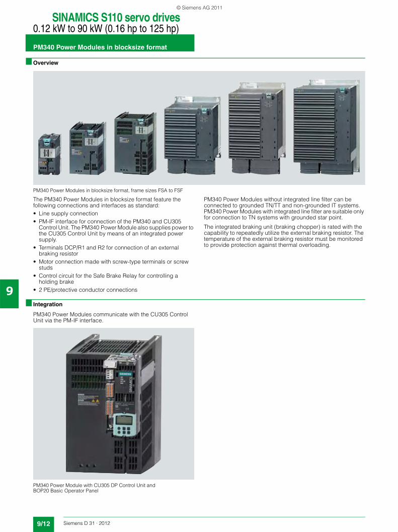
PM340 Power Modules in blocksize format, frame sizes FSA to FSF
The PM340 Power Modules in blocksize format feature the following connections and interfaces as standard:• Line supply connection• PM-IF interface for connection of the PM340 and CU305
Control Unit. The PM340 Power Module also supplies power to the CU305 Control Unit by means of an integrated power supply.
• Terminals DCP/R1 and R2 for connection of an external braking resistor
• Motor connection made with screw-type terminals or screw studs
• Control circuit for the Safe Brake Relay for controlling a holding brake
• 2 PE/protective conductor connections
PM340 Power Modules without integrated line filter can be connected to grounded TN/TT and non-grounded IT systems.PM340 Power Modules with integrated line filter are suitable only for connection to TN systems with grounded star point.
The integrated braking unit (braking chopper) is rated with the capability to repeatedly utilize the external braking resistor. The temperature of the external braking resistor must be monitored to provide protection against thermal overloading.
■ Integration
PM340 Power Modules communicate with the CU305 Control Unit via the PM-IF interface.
PM340 Power Module with CU305 DP Control Unit and BOP20 Basic Operator Panel
© Siemens AG 2011
SINAMICS S110 servo drives0.12 kW to 90 kW (0.16 hp to 125 hp)
PM340 Power Modules in blocksize format
9/13Siemens D 31 · 2012
9
■ Integration
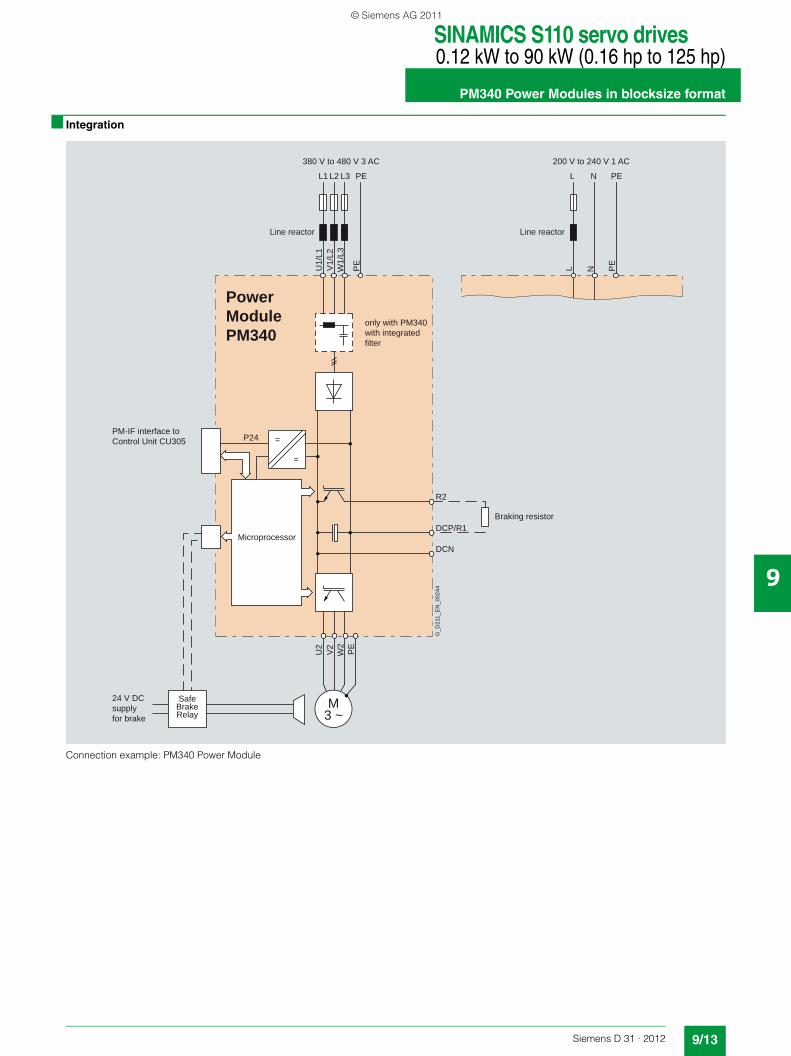
Connection example: PM340 Power Module
P24
Power ModulePM340
U2
V2
=
=
W2
PE
U1/
L1V
1/L2
W1/
L3
PE
L1 L2 L3 PE
M3 ~
R2
DCP/R1
DCN
SafeBrakeRelay
L N PE
L N PE
Line reactor
380 V to 480 V 3 AC
Line reactor
200 V to 240 V 1 AC
PM-IF interface to Control Unit CU305
Microprocessor
only with PM340 with integratedfilter
24 V DCsupplyfor brake
Braking resistor
G_D
211_
EN
_002
44
© Siemens AG 2011

SINAMICS S110 servo drives0.12 kW to 90 kW (0.16 hp to 125 hp)
PM340 Power Modules in blocksize format
9/14 Siemens D 31 · 2012
9
■ Integration
Many system components for PM340 Power Modules are de-signed as base components, i.e. the component is mounted on the baseplate and the PM340 Power Module in front of them in a space-saving construction. Up to two base components can be mounted in front of one another.
✓ = suitable as base typeO = not suitable as base type– = not available (use PM340 Power Modules with integrated
line filter)
Basic layout of a PM340 Power Module with line reactor as base component
The line reactors are equipped with terminals on the line side and with a pre-assembled cable on the PM340 Power Module side. When installed, the mains terminals are at the top on frame sizes FSA to FSC, and at the bottom on frame sizes FSD and FSE.
PM340 Power Module in frame size FSA with line reactor and line filter
If a line filter is installed in addition to the line reactor on frame size FSA, the components must be arranged as shown in the diagram above. In this case, the line supply connection is at the bottom.
PM340 Power Module in frame size FSA with line reactor and motor reactor
PM340 Power Modules of frame size FSB and higher are avail-able with integrated line filters, alleviating the need for an exter-nal line filter.
For configurations involving more than two base-type system components, e.g. line reactor + motor reactor + braking resistor, individual components must be mounted to the side of the PM340 Power Module. In this instance, the line and motor reac-tors must be installed behind the PM340 Power Module and the braking resistor to the side.
FSA FSB FSC FSD FSE FSF
Line filter ✓ – – – – –
Line reactor ✓ ✓ ✓ ✓ ✓ O
Braking resistor ✓ ✓ O O O O
Motor reactor ✓ ✓ ✓ O O O
Power supply
G_D
211_
EN
_000
78a
LinereactorPower
Module
Power supply
G_D
211_
EN
_000
79a
Linereactor
PowerModule
Linefilter
to the motor
Line reactor
G_D
211_
EN
_000
80a
Motor reactor
Power Module
Power supply
Power supply to the motor
Line filter
G_D
211_
EN
_000
81a
Line reactor
Motor reactor
Power Module
© Siemens AG 2011

SINAMICS S110 servo drives0.12 kW to 90 kW (0.16 hp to 125 hp)
PM340 Power Modules in blocksize format
9/15Siemens D 31 · 2012
9
■ Technical specifications
Air-cooled PM340 Power Module in blocksize format6SL3210-1S...
Line supply connection voltage(up to 2000 m (6562 ft) above sea level)
200 V ... 240 V 1 AC ±10 % (in operation -15 % < 1 min) or380 ... 480 V 3 AC ±10 % (in operation -15 % < 1 min)
Line
• Power Modules without integrated line filter Grounded TN/TT systems and non-grounded IT systems
• Power Modules with integrated line filter TN systems with grounded star point
Line frequency 47 … 63 Hz
Line power factorat rated power
• Fundamental power factor (cos ϕ1) >0.96
• Total (λ)
- 200 … 240 V 1 AC 0.45 … 0.7
- 380 … 480 V 3 AC 0.65 … 0.95
Overvoltage categoryacc. to EN 60664-1
Class III
Precharging frequencyof the DC link, max.
1× every 30 s
DC link voltage, approx. 1.35 × line voltage
Output frequency
• Control type Servo 0 … 650 Hz 1)
Electronics power supply 24 V DC -15 %/+20 %
Radio interference suppression
• Standard No radio interference suppression
• With line filter Category C2 according to EN 61800-3
Type of cooling Forced air cooling by means of built-in fan
Ambient or coolant temperature (air)in operation for line-side components, Power Modules
0 … 40 °C (32 … 104 °F) without derating,>40 … 55 °C (>104 … 131 °F) see derating characteristics
Installation altitude Up to 1000 m (3281 ft) above sea level without derating,> 1000 ... 4000 m (3281 ... 13124 ft) above sea level,see derating characteristics
Conformity CE (low-voltage and EMC Directives)
Approvals, according to cULus
Safety Integrated Safety Integrity Level 2 (SIL2) acc. to IEC 61508, Performance Level d (PLd) acc. to ISO 13849-1 and Control Category 3 acc. to ISO 13849-1 or EN 954-1Additional information is provided in chapter Highlights, section Safety Integrated.
1) Note the correlation between max. output frequency, pulse frequency and current derating.
© Siemens AG 2011
SINAMICS S110 servo drives0.12 kW to 90 kW (0.16 hp to 125 hp)
PM340 Power Modules in blocksize format
9/16 Siemens D 31 · 2012
9
■ Technical specifications
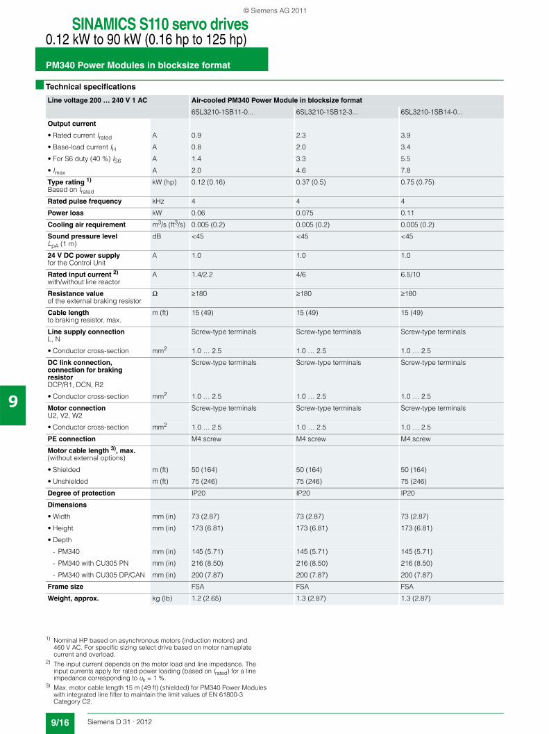
Line voltage 200 … 240 V 1 AC Air-cooled PM340 Power Module in blocksize format
6SL3210-1SB11-0... 6SL3210-1SB12-3... 6SL3210-1SB14-0...
Output current
• Rated current Irated A 0.9 2.3 3.9
• Base-load current IH A 0.8 2.0 3.4
• For S6 duty (40 %) IS6 A 1.4 3.3 5.5
• Imax A 2.0 4.6 7.8
Type rating 1)
Based on Irated
kW (hp) 0.12 (0.16) 0.37 (0.5) 0.75 (0.75)
Rated pulse frequency kHz 4 4 4
Power loss kW 0.06 0.075 0.11
Cooling air requirement m3/s (ft3/s) 0.005 (0.2) 0.005 (0.2) 0.005 (0.2)
Sound pressure levelLpA (1 m)
dB <45 <45 <45
24 V DC power supplyfor the Control Unit
A 1.0 1.0 1.0
Rated input current 2)
with/without line reactorA 1.4/2.2 4/6 6.5/10
Resistance valueof the external braking resistor
Ω ≥180 ≥180 ≥180
Cable lengthto braking resistor, max.
m (ft) 15 (49) 15 (49) 15 (49)
Line supply connectionL, N
Screw-type terminals Screw-type terminals Screw-type terminals
• Conductor cross-section mm2 1.0 … 2.5 1.0 … 2.5 1.0 … 2.5
DC link connection, connection for braking resistorDCP/R1, DCN, R2
Screw-type terminals Screw-type terminals Screw-type terminals
• Conductor cross-section mm2 1.0 … 2.5 1.0 … 2.5 1.0 … 2.5
Motor connectionU2, V2, W2
Screw-type terminals Screw-type terminals Screw-type terminals
• Conductor cross-section mm2 1.0 … 2.5 1.0 … 2.5 1.0 … 2.5
PE connection M4 screw M4 screw M4 screw
Motor cable length 3), max.(without external options)
• Shielded m (ft) 50 (164) 50 (164) 50 (164)
• Unshielded m (ft) 75 (246) 75 (246) 75 (246)
Degree of protection IP20 IP20 IP20
Dimensions
• Width mm (in) 73 (2.87) 73 (2.87) 73 (2.87)
• Height mm (in) 173 (6.81) 173 (6.81) 173 (6.81)
• Depth
- PM340 mm (in) 145 (5.71) 145 (5.71) 145 (5.71)
- PM340 with CU305 PN mm (in) 216 (8.50) 216 (8.50) 216 (8.50)
- PM340 with CU305 DP/CAN mm (in) 200 (7.87) 200 (7.87) 200 (7.87)
Frame size FSA FSA FSA
Weight, approx. kg (lb) 1.2 (2.65) 1.3 (2.87) 1.3 (2.87)
1) Nominal HP based on asynchronous motors (induction motors) and 460 V AC. For specific sizing select drive based on motor nameplate current and overload.
2) The input current depends on the motor load and line impedance. The input currents apply for rated power loading (based on Irated) for a line impedance corresponding to uk = 1 %.
3) Max. motor cable length 15 m (49 ft) (shielded) for PM340 Power Modules with integrated line filter to maintain the limit values of EN 61800-3 Category C2.
© Siemens AG 2011
SINAMICS S110 servo drives0.12 kW to 90 kW (0.16 hp to 125 hp)
PM340 Power Modules in blocksize format
9/17Siemens D 31 · 2012
9
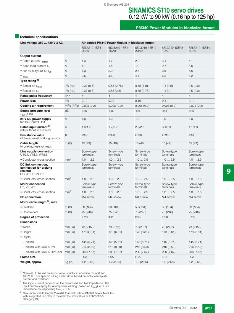
■ Technical specifications
Line voltage 380 … 480 V 3 AC Air-cooled PM340 Power Module in blocksize format
6SL3210-1SE11-3UA0
6SL3210-1SE11-7UA0
6SL3210-1SE12-2UA0
6SL3210-1SE13-1UA0
6SL3210-1SE14-1UA0
Output current
• Rated current Irated A 1.3 1.7 2.2 3.1 4.1
• Base-load current IH A 1.1 1.5 1.9 2.7 3.6
• For S6 duty (40 %) IS6 A 1.3 2.0 2.5 3.5 4.5
• Imax A 2.6 3.4 4.4 6.2 8.2
Type rating 1)
• Based on Irated kW (hp) 0.37 (0.5) 0.55 (0.75) 0.75 (1.0) 1.1 (1.5) 1.5 (2.0)
• Based on IH kW (hp) 0.37 (0.5) 0.55 (0.5) 0.75 (0.75) 1.1 (1) 1.5 (2.0)
Rated pulse frequency kHz 4 4 4 4 4
Power loss kW 0.10 0.10 0.10 0.11 0.11
Cooling air requirement m3/s (ft3/s) 0.005 (0.2) 0.005 (0.2) 0.005 (0.2) 0.005 (0.2) 0.005 (0.2)
Sound pressure levelLpA (1 m)
dB <45 <45 <45 <45 <45
24 V DC power supplyfor the Control Unit
A 1.0 1.0 1.0 1.0 1.0
Rated input current 2)
with/without line reactorA 1.3/1.7 1.7/2.2 2.2/2.6 3.1/3.9 4.1/4.8
Resistance valueof the external braking resistor
Ω ≥390 ≥390 ≥390 ≥390 ≥390
Cable lengthto braking resistor, max.
m (ft) 15 (49) 15 (49) 15 (49) 15 (49) 15 (49)
Line supply connectionU1/L1, V1/L2, W1/L3
Screw-type terminals
Screw-type terminals
Screw-type terminals
Screw-type terminals
Screw-type terminals
• Conductor cross-section mm2 1.0 … 2.5 1.0 … 2.5 1.0 … 2.5 1.0 … 2.5 1.0 … 2.5
DC link connection, connection for braking resistorDCP/R1, DCN, R2
Screw-type terminals
Screw-type terminals
Screw-type terminals
Screw-type terminals
Screw-type terminals
• Conductor cross-section mm2 1.0 … 2.5 1.0 … 2.5 1.0 … 2.5 1.0 … 2.5 1.0 … 2.5
Motor connectionU2, V2, W2
Screw-type terminals
Screw-type terminals
Screw-type terminals
Screw-type terminals
Screw-type terminals
• Conductor cross-section mm2 1.0 … 2.5 1.0 … 2.5 1.0 … 2.5 1.0 … 2.5 1.0 … 2.5
PE connection M4 screw M4 screw M4 screw M4 screw M4 screw
Motor cable length 3), max.
• Shielded m (ft) 50 (164) 50 (164) 50 (164) 50 (164) 50 (164)
• Unshielded m (ft) 75 (246) 75 (246) 75 (246) 75 (246) 75 (246)
Degree of protection IP20 IP20 IP20 IP20 IP20
Dimensions
• Width mm (in) 73 (2.87) 73 (2.87) 73 (2.87) 73 (2.87) 73 (2.87)
• Height mm (in) 173 (6.81) 173 (6.81) 173 (6.81) 173 (6.81) 173 (6.81)
• Depth
- PM340 mm (in) 145 (5.71) 145 (5.71) 145 (5.71) 145 (5.71) 145 (5.71)
- PM340 with CU305 PN mm (in) 216 (8.50) 216 (8.50) 216 (8.50) 216 (8.50) 216 (8.50)
- PM340 with CU305 DP/CAN mm (in) 200 (7.87) 200 (7.87) 200 (7.87) 200 (7.87) 200 (7.87)
Frame size FSA FSA FSA FSA FSA
Weight, approx. kg (lb) 1.2 (2.65) 1.2 (2.65) 1.2 (2.65) 1.2 (2.65) 1.2 (2.65)
1) Nominal HP based on asynchronous motors (induction motors) and 460 V AC. For specific sizing select drive based on motor nameplate current and overload.
2) The input current depends on the motor load and line impedance. The input currents apply for rated power loading (based on Irated) for a line impedance corresponding to uk = 1 %.
3) Max. motor cable length 25 m (82 ft) (shielded) for PM340 Power Modules with integrated line filter to maintain the limit values of EN 61800-3 Category C2.
© Siemens AG 2011
SINAMICS S110 servo drives0.12 kW to 90 kW (0.16 hp to 125 hp)
PM340 Power Modules in blocksize format
9/18 Siemens D 31 · 2012
9
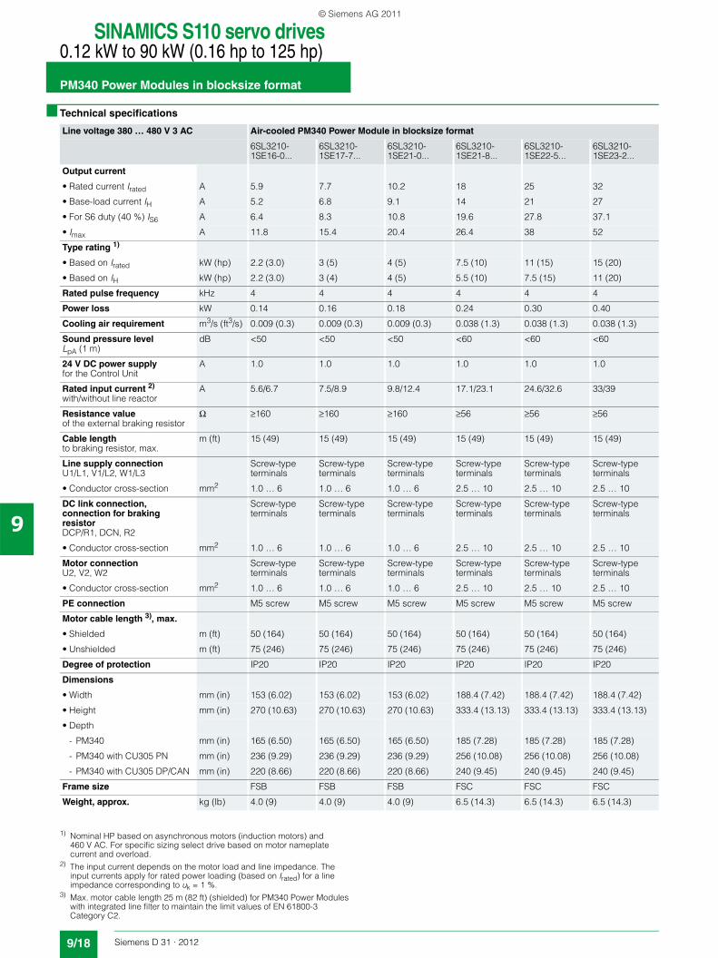
■ Technical specifications
Line voltage 380 … 480 V 3 AC Air-cooled PM340 Power Module in blocksize format
6SL3210-1SE16-0...
6SL3210-1SE17-7...
6SL3210-1SE21-0...
6SL3210-1SE21-8...
6SL3210-1SE22-5...
6SL3210-1SE23-2...
Output current
• Rated current Irated A 5.9 7.7 10.2 18 25 32
• Base-load current IH A 5.2 6.8 9.1 14 21 27
• For S6 duty (40 %) IS6 A 6.4 8.3 10.8 19.6 27.8 37.1
• Imax A 11.8 15.4 20.4 26.4 38 52
Type rating 1)
• Based on Irated kW (hp) 2.2 (3.0) 3 (5) 4 (5) 7.5 (10) 11 (15) 15 (20)
• Based on IH kW (hp) 2.2 (3.0) 3 (4) 4 (5) 5.5 (10) 7.5 (15) 11 (20)
Rated pulse frequency kHz 4 4 4 4 4 4
Power loss kW 0.14 0.16 0.18 0.24 0.30 0.40
Cooling air requirement m3/s (ft3/s) 0.009 (0.3) 0.009 (0.3) 0.009 (0.3) 0.038 (1.3) 0.038 (1.3) 0.038 (1.3)
Sound pressure levelLpA (1 m)
dB <50 <50 <50 <60 <60 <60
24 V DC power supplyfor the Control Unit
A 1.0 1.0 1.0 1.0 1.0 1.0
Rated input current 2)
with/without line reactorA 5.6/6.7 7.5/8.9 9.8/12.4 17.1/23.1 24.6/32.6 33/39
Resistance valueof the external braking resistor
Ω ≥160 ≥160 ≥160 ≥56 ≥56 ≥56
Cable lengthto braking resistor, max.
m (ft) 15 (49) 15 (49) 15 (49) 15 (49) 15 (49) 15 (49)
Line supply connectionU1/L1, V1/L2, W1/L3
Screw-type terminals
Screw-type terminals
Screw-type terminals
Screw-type terminals
Screw-type terminals
Screw-type terminals
• Conductor cross-section mm2 1.0 … 6 1.0 … 6 1.0 … 6 2.5 … 10 2.5 … 10 2.5 … 10
DC link connection, connection for braking resistorDCP/R1, DCN, R2
Screw-type terminals
Screw-type terminals
Screw-type terminals
Screw-type terminals
Screw-type terminals
Screw-type terminals
• Conductor cross-section mm2 1.0 … 6 1.0 … 6 1.0 … 6 2.5 … 10 2.5 … 10 2.5 … 10
Motor connectionU2, V2, W2
Screw-type terminals
Screw-type terminals
Screw-type terminals
Screw-type terminals
Screw-type terminals
Screw-type terminals
• Conductor cross-section mm2 1.0 … 6 1.0 … 6 1.0 … 6 2.5 … 10 2.5 … 10 2.5 … 10
PE connection M5 screw M5 screw M5 screw M5 screw M5 screw M5 screw
Motor cable length 3), max.
• Shielded m (ft) 50 (164) 50 (164) 50 (164) 50 (164) 50 (164) 50 (164)
• Unshielded m (ft) 75 (246) 75 (246) 75 (246) 75 (246) 75 (246) 75 (246)
Degree of protection IP20 IP20 IP20 IP20 IP20 IP20
Dimensions
• Width mm (in) 153 (6.02) 153 (6.02) 153 (6.02) 188.4 (7.42) 188.4 (7.42) 188.4 (7.42)
• Height mm (in) 270 (10.63) 270 (10.63) 270 (10.63) 333.4 (13.13) 333.4 (13.13) 333.4 (13.13)
• Depth
- PM340 mm (in) 165 (6.50) 165 (6.50) 165 (6.50) 185 (7.28) 185 (7.28) 185 (7.28)
- PM340 with CU305 PN mm (in) 236 (9.29) 236 (9.29) 236 (9.29) 256 (10.08) 256 (10.08) 256 (10.08)
- PM340 with CU305 DP/CAN mm (in) 220 (8.66) 220 (8.66) 220 (8.66) 240 (9.45) 240 (9.45) 240 (9.45)
Frame size FSB FSB FSB FSC FSC FSC
Weight, approx. kg (lb) 4.0 (9) 4.0 (9) 4.0 (9) 6.5 (14.3) 6.5 (14.3) 6.5 (14.3)
1) Nominal HP based on asynchronous motors (induction motors) and 460 V AC. For specific sizing select drive based on motor nameplate current and overload.
2) The input current depends on the motor load and line impedance. The input currents apply for rated power loading (based on Irated) for a line impedance corresponding to uk = 1 %.
3) Max. motor cable length 25 m (82 ft) (shielded) for PM340 Power Modules with integrated line filter to maintain the limit values of EN 61800-3 Category C2.
© Siemens AG 2011
SINAMICS S110 servo drives0.12 kW to 90 kW (0.16 hp to 125 hp)
PM340 Power Modules in blocksize format
9/19Siemens D 31 · 2012
9
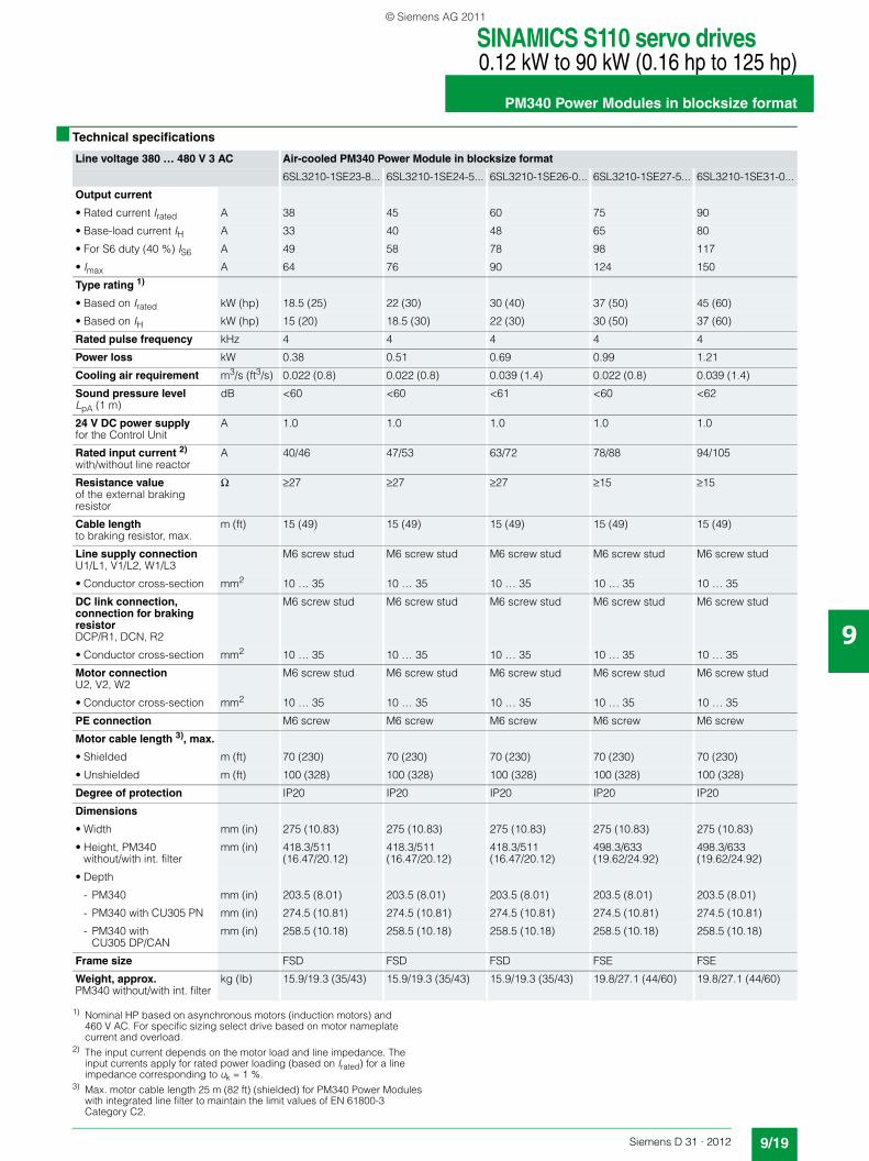
■ Technical specifications
Line voltage 380 … 480 V 3 AC Air-cooled PM340 Power Module in blocksize format
6SL3210-1SE23-8... 6SL3210-1SE24-5... 6SL3210-1SE26-0... 6SL3210-1SE27-5... 6SL3210-1SE31-0...
Output current
• Rated current Irated A 38 45 60 75 90
• Base-load current IH A 33 40 48 65 80
• For S6 duty (40 %) IS6 A 49 58 78 98 117
• Imax A 64 76 90 124 150
Type rating 1)
• Based on Irated kW (hp) 18.5 (25) 22 (30) 30 (40) 37 (50) 45 (60)
• Based on IH kW (hp) 15 (20) 18.5 (30) 22 (30) 30 (50) 37 (60)
Rated pulse frequency kHz 4 4 4 4 4
Power loss kW 0.38 0.51 0.69 0.99 1.21
Cooling air requirement m3/s (ft3/s) 0.022 (0.8) 0.022 (0.8) 0.039 (1.4) 0.022 (0.8) 0.039 (1.4)
Sound pressure levelLpA (1 m)
dB <60 <60 <61 <60 <62
24 V DC power supplyfor the Control Unit
A 1.0 1.0 1.0 1.0 1.0
Rated input current 2)
with/without line reactorA 40/46 47/53 63/72 78/88 94/105
Resistance valueof the external braking resistor
Ω ≥27 ≥27 ≥27 ≥15 ≥15
Cable lengthto braking resistor, max.
m (ft) 15 (49) 15 (49) 15 (49) 15 (49) 15 (49)
Line supply connectionU1/L1, V1/L2, W1/L3
M6 screw stud M6 screw stud M6 screw stud M6 screw stud M6 screw stud
• Conductor cross-section mm2 10 … 35 10 … 35 10 … 35 10 … 35 10 … 35
DC link connection, connection for braking resistorDCP/R1, DCN, R2
M6 screw stud M6 screw stud M6 screw stud M6 screw stud M6 screw stud
• Conductor cross-section mm2 10 … 35 10 … 35 10 … 35 10 … 35 10 … 35
Motor connectionU2, V2, W2
M6 screw stud M6 screw stud M6 screw stud M6 screw stud M6 screw stud
• Conductor cross-section mm2 10 … 35 10 … 35 10 … 35 10 … 35 10 … 35
PE connection M6 screw M6 screw M6 screw M6 screw M6 screw
Motor cable length 3), max.
• Shielded m (ft) 70 (230) 70 (230) 70 (230) 70 (230) 70 (230)
• Unshielded m (ft) 100 (328) 100 (328) 100 (328) 100 (328) 100 (328)
Degree of protection IP20 IP20 IP20 IP20 IP20
Dimensions
• Width mm (in) 275 (10.83) 275 (10.83) 275 (10.83) 275 (10.83) 275 (10.83)
• Height, PM340without/with int. filter
mm (in) 418.3/511 (16.47/20.12)
418.3/511 (16.47/20.12)
418.3/511 (16.47/20.12)
498.3/633 (19.62/24.92)
498.3/633 (19.62/24.92)
• Depth
- PM340 mm (in) 203.5 (8.01) 203.5 (8.01) 203.5 (8.01) 203.5 (8.01) 203.5 (8.01)
- PM340 with CU305 PN mm (in) 274.5 (10.81) 274.5 (10.81) 274.5 (10.81) 274.5 (10.81) 274.5 (10.81)
- PM340 with CU305 DP/CAN
mm (in) 258.5 (10.18) 258.5 (10.18) 258.5 (10.18) 258.5 (10.18) 258.5 (10.18)
Frame size FSD FSD FSD FSE FSE
Weight, approx.PM340 without/with int. filter
kg (lb) 15.9/19.3 (35/43) 15.9/19.3 (35/43) 15.9/19.3 (35/43) 19.8/27.1 (44/60) 19.8/27.1 (44/60)
1) Nominal HP based on asynchronous motors (induction motors) and 460 V AC. For specific sizing select drive based on motor nameplate current and overload.
2) The input current depends on the motor load and line impedance. The input currents apply for rated power loading (based on Irated) for a line impedance corresponding to uk = 1 %.
3) Max. motor cable length 25 m (82 ft) (shielded) for PM340 Power Modules with integrated line filter to maintain the limit values of EN 61800-3 Category C2.
© Siemens AG 2011
SINAMICS S110 servo drives0.12 kW to 90 kW (0.16 hp to 125 hp)
PM340 Power Modules in blocksize format
9/20 Siemens D 31 · 2012
9
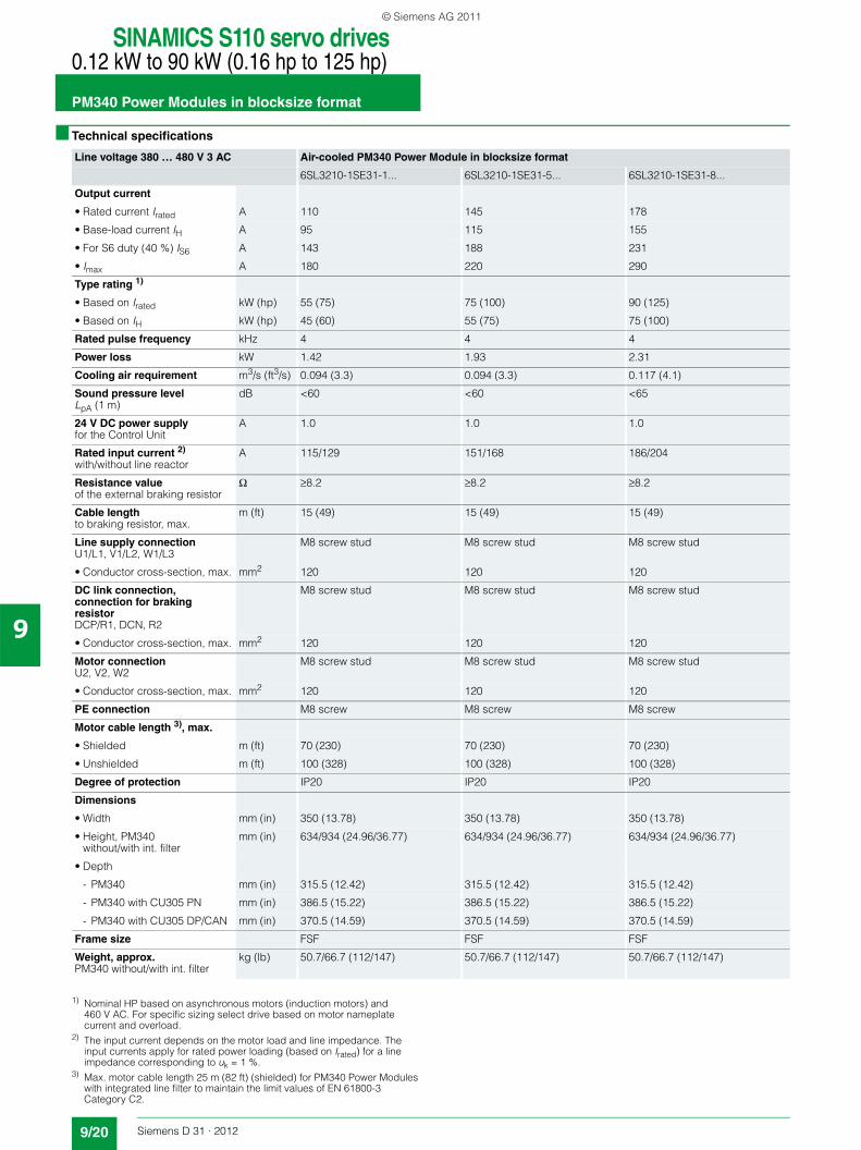
■ Technical specifications
Line voltage 380 … 480 V 3 AC Air-cooled PM340 Power Module in blocksize format
6SL3210-1SE31-1... 6SL3210-1SE31-5... 6SL3210-1SE31-8...
Output current
• Rated current Irated A 110 145 178
• Base-load current IH A 95 115 155
• For S6 duty (40 %) IS6 A 143 188 231
• Imax A 180 220 290
Type rating 1)
• Based on Irated kW (hp) 55 (75) 75 (100) 90 (125)
• Based on IH kW (hp) 45 (60) 55 (75) 75 (100)
Rated pulse frequency kHz 4 4 4
Power loss kW 1.42 1.93 2.31
Cooling air requirement m3/s (ft3/s) 0.094 (3.3) 0.094 (3.3) 0.117 (4.1)
Sound pressure levelLpA (1 m)
dB <60 <60 <65
24 V DC power supplyfor the Control Unit
A 1.0 1.0 1.0
Rated input current 2)
with/without line reactorA 115/129 151/168 186/204
Resistance valueof the external braking resistor
Ω ≥8.2 ≥8.2 ≥8.2
Cable lengthto braking resistor, max.
m (ft) 15 (49) 15 (49) 15 (49)
Line supply connectionU1/L1, V1/L2, W1/L3
M8 screw stud M8 screw stud M8 screw stud
• Conductor cross-section, max. mm2 120 120 120
DC link connection, connection for braking resistorDCP/R1, DCN, R2
M8 screw stud M8 screw stud M8 screw stud
• Conductor cross-section, max. mm2 120 120 120
Motor connectionU2, V2, W2
M8 screw stud M8 screw stud M8 screw stud
• Conductor cross-section, max. mm2 120 120 120
PE connection M8 screw M8 screw M8 screw
Motor cable length 3), max.
• Shielded m (ft) 70 (230) 70 (230) 70 (230)
• Unshielded m (ft) 100 (328) 100 (328) 100 (328)
Degree of protection IP20 IP20 IP20
Dimensions
• Width mm (in) 350 (13.78) 350 (13.78) 350 (13.78)
• Height, PM340without/with int. filter
mm (in) 634/934 (24.96/36.77) 634/934 (24.96/36.77) 634/934 (24.96/36.77)
• Depth
- PM340 mm (in) 315.5 (12.42) 315.5 (12.42) 315.5 (12.42)
- PM340 with CU305 PN mm (in) 386.5 (15.22) 386.5 (15.22) 386.5 (15.22)
- PM340 with CU305 DP/CAN mm (in) 370.5 (14.59) 370.5 (14.59) 370.5 (14.59)
Frame size FSF FSF FSF
Weight, approx.PM340 without/with int. filter
kg (lb) 50.7/66.7 (112/147) 50.7/66.7 (112/147) 50.7/66.7 (112/147)
1) Nominal HP based on asynchronous motors (induction motors) and 460 V AC. For specific sizing select drive based on motor nameplate current and overload.
2) The input current depends on the motor load and line impedance. The input currents apply for rated power loading (based on Irated) for a line impedance corresponding to uk = 1 %.
3) Max. motor cable length 25 m (82 ft) (shielded) for PM340 Power Modules with integrated line filter to maintain the limit values of EN 61800-3 Category C2.
© Siemens AG 2011
SINAMICS S110 servo drives0.12 kW to 90 kW (0.16 hp to 125 hp)
PM340 Power Modules in blocksize format
9/21Siemens D 31 · 2012
9
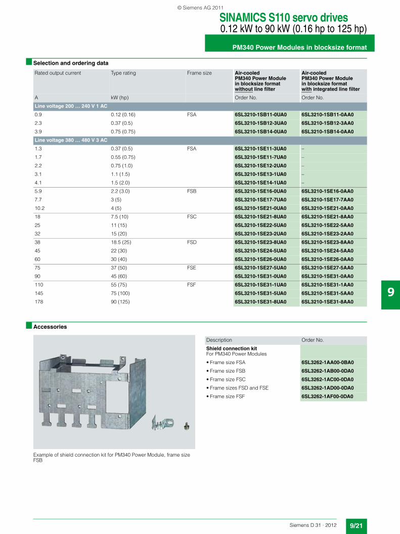
■ Selection and ordering data
■ Accessories
Example of shield connection kit for PM340 Power Module, frame size FSB
Rated output current Type rating Frame size Air-cooled PM340 Power Module in blocksize formatwithout line filter
Air-cooled PM340 Power Module in blocksize formatwith integrated line filter
A kW (hp) Order No. Order No.
Line voltage 200 … 240 V 1 AC
0.9 0.12 (0.16) FSA 6SL3210-1SB11-0UA0 6SL3210-1SB11-0AA0
2.3 0.37 (0.5) 6SL3210-1SB12-3UA0 6SL3210-1SB12-3AA0
3.9 0.75 (0.75) 6SL3210-1SB14-0UA0 6SL3210-1SB14-0AA0
Line voltage 380 … 480 V 3 AC
1.3 0.37 (0.5) FSA 6SL3210-1SE11-3UA0 –
1.7 0.55 (0.75) 6SL3210-1SE11-7UA0 –
2.2 0.75 (1.0) 6SL3210-1SE12-2UA0 –
3.1 1.1 (1.5) 6SL3210-1SE13-1UA0 –
4.1 1.5 (2.0) 6SL3210-1SE14-1UA0 –
5.9 2.2 (3.0) FSB 6SL3210-1SE16-0UA0 6SL3210-1SE16-0AA0
7.7 3 (5) 6SL3210-1SE17-7UA0 6SL3210-1SE17-7AA0
10.2 4 (5) 6SL3210-1SE21-0UA0 6SL3210-1SE21-0AA0
18 7.5 (10) FSC 6SL3210-1SE21-8UA0 6SL3210-1SE21-8AA0
25 11 (15) 6SL3210-1SE22-5UA0 6SL3210-1SE22-5AA0
32 15 (20) 6SL3210-1SE23-2UA0 6SL3210-1SE23-2AA0
38 18.5 (25) FSD 6SL3210-1SE23-8UA0 6SL3210-1SE23-8AA0
45 22 (30) 6SL3210-1SE24-5UA0 6SL3210-1SE24-5AA0
60 30 (40) 6SL3210-1SE26-0UA0 6SL3210-1SE26-0AA0
75 37 (50) FSE 6SL3210-1SE27-5UA0 6SL3210-1SE27-5AA0
90 45 (60) 6SL3210-1SE31-0UA0 6SL3210-1SE31-0AA0
110 55 (75) FSF 6SL3210-1SE31-1UA0 6SL3210-1SE31-1AA0
145 75 (100) 6SL3210-1SE31-5UA0 6SL3210-1SE31-5AA0
178 90 (125) 6SL3210-1SE31-8UA0 6SL3210-1SE31-8AA0
Description Order No.
Shield connection kitFor PM340 Power Modules
• Frame size FSA 6SL3262-1AA00-0BA0
• Frame size FSB 6SL3262-1AB00-0DA0
• Frame size FSC 6SL3262-1AC00-0DA0
• Frame sizes FSD and FSE 6SL3262-1AD00-0DA0
• Frame size FSF 6SL3262-1AF00-0DA0
© Siemens AG 2011
SINAMICS S110 servo drives0.12 kW to 90 kW (0.16 hp to 125 hp)
PM340 Power Modules in blocksize format
9/22 Siemens D 31 · 2012
9
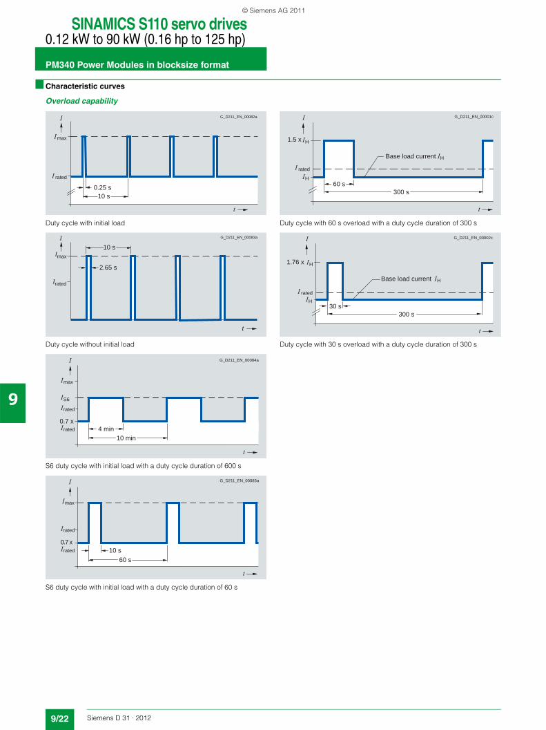
■ Characteristic curves
Overload capability
Duty cycle with initial load
Duty cycle without initial load
S6 duty cycle with initial load with a duty cycle duration of 600 s
S6 duty cycle with initial load with a duty cycle duration of 60 s
Duty cycle with 60 s overload with a duty cycle duration of 300 s
Duty cycle with 30 s overload with a duty cycle duration of 300 s
10 s
rated
max
G_D211_EN_00082a
0.25 s
Imax
G_D211_EN_00083a
2.65 s
Irated
10 sI
t
10 min4 minrated
0.7 x
G_D211_EN_00084a
rated
S6
max
60 s10 srated
0.7 x
G_D211_EN_00085a
rated
max
300 s60 s
H
H
rated
Base load current
1.5 x
G_D211_EN_00001c
H
H
H
300 s30 s
rated
G_D211_EN_00002c
HBase load current
1.76 x
© Siemens AG 2011
SINAMICS S110 servo drives0.12 kW to 90 kW (0.16 hp to 125 hp)
PM340 Power Modules in blocksize format
9/23Siemens D 31 · 2012
9
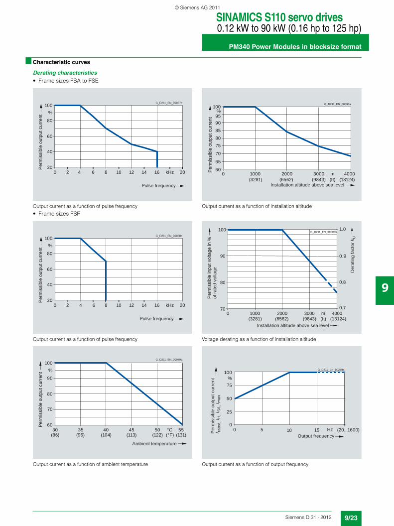
■ Characteristic curves
Derating characteristics• Frame sizes FSA to FSE
Output current as a function of pulse frequency
• Frame sizes FSF
Output current as a function of pulse frequency
Output current as a function of ambient temperature
Output current as a function of installation altitude
Voltage derating as a function of installation altitude
Output current as a function of output frequency
100
80
60
40
204 6 8 10 12 14 16 2020
%
kHz
G_D211_EN_00087a
Per
mis
sibl
e ou
tput
cur
rent
Pulse frequency
100
80
60
40
204 6 8 10 12 14 16 2020
%
kHz
G_D211_EN_00088a
Per
mis
sibl
e ou
tput
cur
rent
Pulse frequency
100
90
80
70
603530 40 45 50 55
%
°C
G_D211_EN_00089a
Per
mis
sibl
e ou
tput
cur
rent
Ambient temperature
(86) (95) (104) (113) (122) (131)(°F)
100
9590858075
3000200010000 4000
70
65
60
%
m
G_D211_EN_00090a
Per
mis
sibl
e ou
tput
cur
rent
Installation altitude above sea level(ft)(3281) (6562) (9843) (13124)
1000 2000 m0 3000 4000
100
90
80
70
(3281) (6562) (9843) (ft) (13124)
1.0
0.9
0.7
0.8
Der
atin
g fa
ctor
kU
Installation altitude above sea level
Per
mis
sibl
e in
put v
olta
ge in
%of
rate
d vo
ltage
G_D211_EN_00006b
Output frequency
G_D211_EN_00249a
Per
mis
sibl
e ou
tput
cur
rent
I ra
ted,
I H, I
S6,
I max
100
75
50
(20...1600)100
25
0
%
Hz5 15
© Siemens AG 2011
SINAMICS S110 servo drives0.12 kW to 90 kW (0.16 hp to 125 hp)Line-side componentsLine reactors
9/24 Siemens D 31 · 2012
9
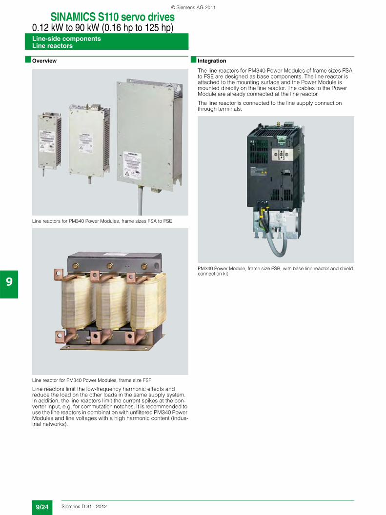
■ Overview
Line reactors for PM340 Power Modules, frame sizes FSA to FSE
Line reactor for PM340 Power Modules, frame size FSF
Line reactors limit the low-frequency harmonic effects and reduce the load on the other loads in the same supply system. In addition, the line reactors limit the current spikes at the con-verter input, e.g. for commutation notches. It is recommended to use the line reactors in combination with unfiltered PM340 Power Modules and line voltages with a high harmonic content (indus-trial networks).
■ Integration
The line reactors for PM340 Power Modules of frame sizes FSA to FSE are designed as base components. The line reactor is attached to the mounting surface and the Power Module is mounted directly on the line reactor. The cables to the Power Module are already connected at the line reactor.
The line reactor is connected to the line supply connection through terminals.
PM340 Power Module, frame size FSB, with base line reactor and shield connection kit
© Siemens AG 2011
SINAMICS S110 servo drives0.12 kW to 90 kW (0.16 hp to 125 hp)
Line-side componentsLine reactors
9/25Siemens D 31 · 2012
9
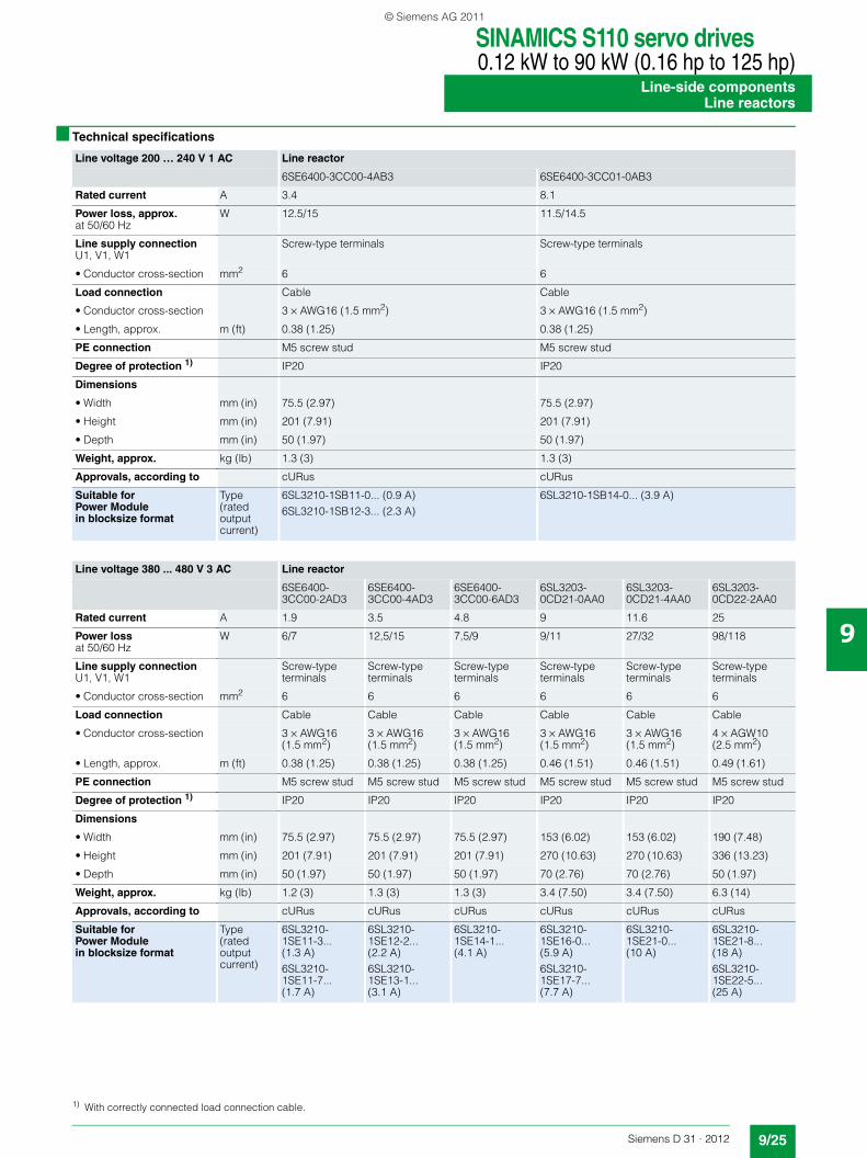
■ Technical specifications
Line voltage 200 … 240 V 1 AC Line reactor
6SE6400-3CC00-4AB3 6SE6400-3CC01-0AB3
Rated current A 3.4 8.1
Power loss, approx.at 50/60 Hz
W 12.5/15 11.5/14.5
Line supply connectionU1, V1, W1
Screw-type terminals Screw-type terminals
• Conductor cross-section mm2 6 6
Load connection Cable Cable
• Conductor cross-section 3 × AWG16 (1.5 mm2) 3 × AWG16 (1.5 mm2)
• Length, approx. m (ft) 0.38 (1.25) 0.38 (1.25)
PE connection M5 screw stud M5 screw stud
Degree of protection 1) IP20 IP20
Dimensions
• Width mm (in) 75.5 (2.97) 75.5 (2.97)
• Height mm (in) 201 (7.91) 201 (7.91)
• Depth mm (in) 50 (1.97) 50 (1.97)
Weight, approx. kg (lb) 1.3 (3) 1.3 (3)
Approvals, according to cURus cURus
Suitable for Power Modulein blocksize format
Type (rated output current)
6SL3210-1SB11-0... (0.9 A)6SL3210-1SB12-3... (2.3 A)
6SL3210-1SB14-0... (3.9 A)
Line voltage 380 ... 480 V 3 AC Line reactor
6SE6400-3CC00-2AD3
6SE6400-3CC00-4AD3
6SE6400-3CC00-6AD3
6SL3203-0CD21-0AA0
6SL3203-0CD21-4AA0
6SL3203-0CD22-2AA0
Rated current A 1.9 3.5 4.8 9 11.6 25
Power lossat 50/60 Hz
W 6/7 12,5/15 7,5/9 9/11 27/32 98/118
Line supply connectionU1, V1, W1
Screw-type terminals
Screw-type terminals
Screw-type terminals
Screw-type terminals
Screw-type terminals
Screw-type terminals
• Conductor cross-section mm2 6 6 6 6 6 6
Load connection Cable Cable Cable Cable Cable Cable
• Conductor cross-section 3 × AWG16 (1.5 mm2)
3 × AWG16 (1.5 mm2)
3 × AWG16 (1.5 mm2)
3 × AWG16 (1.5 mm2)
3 × AWG16 (1.5 mm2)
4 × AGW10 (2.5 mm2)
• Length, approx. m (ft) 0.38 (1.25) 0.38 (1.25) 0.38 (1.25) 0.46 (1.51) 0.46 (1.51) 0.49 (1.61)
PE connection M5 screw stud M5 screw stud M5 screw stud M5 screw stud M5 screw stud M5 screw stud
Degree of protection 1) IP20 IP20 IP20 IP20 IP20 IP20
Dimensions
• Width mm (in) 75.5 (2.97) 75.5 (2.97) 75.5 (2.97) 153 (6.02) 153 (6.02) 190 (7.48)
• Height mm (in) 201 (7.91) 201 (7.91) 201 (7.91) 270 (10.63) 270 (10.63) 336 (13.23)
• Depth mm (in) 50 (1.97) 50 (1.97) 50 (1.97) 70 (2.76) 70 (2.76) 50 (1.97)
Weight, approx. kg (lb) 1.2 (3) 1.3 (3) 1.3 (3) 3.4 (7.50) 3.4 (7.50) 6.3 (14)
Approvals, according to cURus cURus cURus cURus cURus cURus
Suitable for Power Module in blocksize format
Type (rated output current)
6SL3210-1SE11-3... (1.3 A)6SL3210-1SE11-7... (1.7 A)
6SL3210-1SE12-2... (2.2 A)6SL3210-1SE13-1... (3.1 A)
6SL3210-1SE14-1... (4.1 A)
6SL3210-1SE16-0... (5.9 A)6SL3210-1SE17-7... (7.7 A)
6SL3210-1SE21-0... (10 A)
6SL3210-1SE21-8... (18 A)6SL3210-1SE22-5... (25 A)
1) With correctly connected load connection cable.
© Siemens AG 2011
SINAMICS S110 servo drives0.12 kW to 90 kW (0.16 hp to 125 hp)Line-side componentsLine reactors
9/26 Siemens D 31 · 2012
9
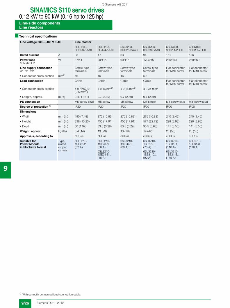
■ Technical specifications
Line voltage 380 ... 480 V 3 AC Line reactor
6SL3203-0CD23-5AA0
6SL3203-0CJ24-5AA0
6SL3203-0CD25-3AA0
6SL3203-0CJ28-6AA0
6SE6400-3CC11-2FD0
6SE6400-3CC11-7FD0
Rated current A 33 47 63 94 151 186
Power lossat 50/60 Hz
W 37/44 90/115 90/115 170/215 280/360 280/360
Line supply connectionU1, V1, W1
Screw-type terminals
Screw-type terminals
Screw-type terminals
Screw-type terminals
Flat connector for M10 screw
Flat connector for M10 screw
• Conductor cross-section mm2 16 16 16 50 – –
Load connection Cable Cable Cable Cable Flat connector for M10 screw
Flat connector for M10 screw
• Conductor cross-section 4 × AWG10 (2.5 mm2)
4 × 16 mm2 4 × 16 mm2 4 × 35 mm2 – –
• Length, approx. m (ft) 0.49 (1.61) 0.7 (2.30) 0.7 (2.30) 0.7 (2.30)
PE connection M5 screw stud M8 screw M8 screw M8 screw M8 screw stud M8 screw stud
Degree of protection 1) IP20 IP20 IP20 IP20 IP00 IP00
Dimensions
• Width mm (in) 190 (7.48) 275 (10.83) 275 (10.83) 275 (10.83) 240 (9.45) 240 (9.45)
• Height mm (in) 336 (13.23) 455 (17.91) 455 (17.91) 577 (22.72) 228 (8.98) 228 (8.98)
• Depth mm (in) 50 (1.97) 83.5 (3.29) 83.5 (3.29) 93.5 (3.68) 141 (5.55) 141 (5.55)
Weight, approx. kg (lb) 6.4 (14) 13 (29) 13 (29) 19 (42) 25 (55) 25 (55)
Approvals, according to cURus cURus cURus cURus cURus cURus
Suitable for Power Module in blocksize format
Type (rated output current)
6SL3210-1SE23-2... (32 A)
6SL3210-1SE23-8... (38 A)6SL3210-1SE24-5... (45 A)
6SL3210-1SE26-0... (60 A)
6SL3210-1SE27-5... (75 A)6SL3210-1SE31-0... (90 A)
6SL3210-1SE31-1... (110 A)6SL3210-1SE31-5... (145 A)
6SL3210-1SE31-8... (178 A)
1) With correctly connected load connection cable.
© Siemens AG 2011
SINAMICS S110 servo drives0.12 kW to 90 kW (0.16 hp to 125 hp)
Line-side componentsLine reactors
9/27Siemens D 31 · 2012
9
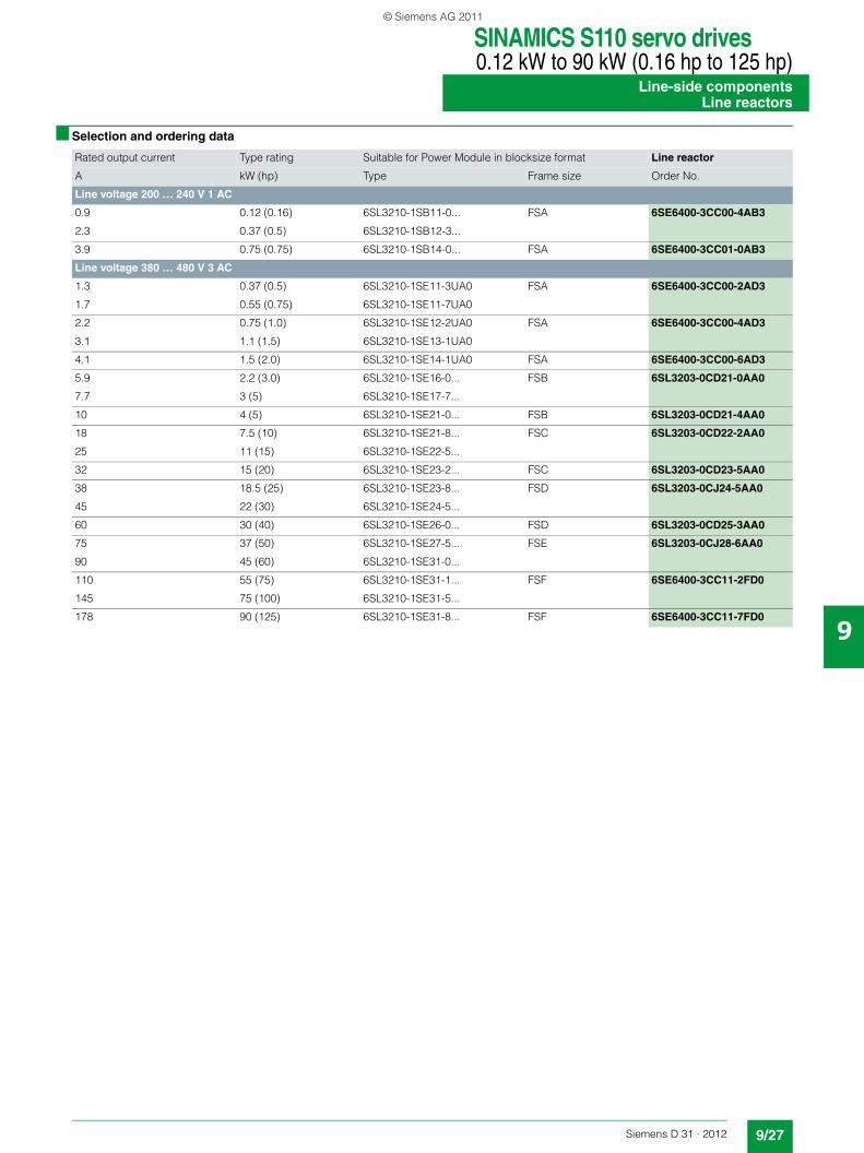
■ Selection and ordering data
Rated output current Type rating Suitable for Power Module in blocksize format Line reactor
A kW (hp) Type Frame size Order No.
Line voltage 200 … 240 V 1 AC
0.9 0.12 (0.16) 6SL3210-1SB11-0... FSA 6SE6400-3CC00-4AB3
2.3 0.37 (0.5) 6SL3210-1SB12-3...
3.9 0.75 (0.75) 6SL3210-1SB14-0... FSA 6SE6400-3CC01-0AB3
Line voltage 380 … 480 V 3 AC
1.3 0.37 (0.5) 6SL3210-1SE11-3UA0 FSA 6SE6400-3CC00-2AD3
1.7 0.55 (0.75) 6SL3210-1SE11-7UA0
2.2 0.75 (1.0) 6SL3210-1SE12-2UA0 FSA 6SE6400-3CC00-4AD3
3.1 1.1 (1.5) 6SL3210-1SE13-1UA0
4.1 1.5 (2.0) 6SL3210-1SE14-1UA0 FSA 6SE6400-3CC00-6AD3
5.9 2.2 (3.0) 6SL3210-1SE16-0... FSB 6SL3203-0CD21-0AA0
7.7 3 (5) 6SL3210-1SE17-7...
10 4 (5) 6SL3210-1SE21-0... FSB 6SL3203-0CD21-4AA0
18 7.5 (10) 6SL3210-1SE21-8... FSC 6SL3203-0CD22-2AA0
25 11 (15) 6SL3210-1SE22-5...
32 15 (20) 6SL3210-1SE23-2... FSC 6SL3203-0CD23-5AA0
38 18.5 (25) 6SL3210-1SE23-8... FSD 6SL3203-0CJ24-5AA0
45 22 (30) 6SL3210-1SE24-5...
60 30 (40) 6SL3210-1SE26-0... FSD 6SL3203-0CD25-3AA0
75 37 (50) 6SL3210-1SE27-5... FSE 6SL3203-0CJ28-6AA0
90 45 (60) 6SL3210-1SE31-0...
110 55 (75) 6SL3210-1SE31-1... FSF 6SE6400-3CC11-2FD0
145 75 (100) 6SL3210-1SE31-5...
178 90 (125) 6SL3210-1SE31-8... FSF 6SE6400-3CC11-7FD0
© Siemens AG 2011

SINAMICS S110 servo drives0.12 kW to 90 kW (0.16 hp to 125 hp)Line-side componentsLine filter
9/28 Siemens D 31 · 2012
9
■ Overview
In plants with strict EMC requirements, the line filter for frame size FSA restricts the conducted interference emanating from the PM340 Power Module to the limit values of Category C2 as defined in EN 61800-3. The line filter is suited only for direct connection to TN (grounded) systems.
Note:
The line filter is designed only for PM340 Power Modules of frame size FSA and a line voltage of 380 V to 480 V 3 AC. All other PM340 Power Modules are available with integrated line filter.
■ Integration
Line filter, line reactor and Power Module can be mounted in front of one another.
■ Technical specifications
■ Selection and ordering data
Power supply
G_D
211_
EN
_000
79a
Linereactor
PowerModule
Linefilter
Line voltage 380 … 480 V 3 AC Line filter6SE6400-2FA00-6AD0
Rated current 6 A
Power loss <5 W
Line supply connectionL1, L2, L3
Screw-type terminals
• Conductor cross-section 1 ... 2.5 mm2
PE connection M4 screw stud
Load connectionU, V, W, PE
Shielded cable
• Conductor cross-section 4 × 1.5 mm2
• Length, approx. 0.24 m (0.79 ft)
Degree of protection IP20 (with correctly connected load connection cable)
Dimensions
• Width 73.5 mm (2.89 in)
• Height 200 mm (7.87 in)
• Depth 44 mm (1.73 in)
Weight, approx. 0.5 kg (1 lb)
Approvals, according to cURus
Suitable for Power Module in blocksize formatType (rated output current)
6SL3210-1SE11-... (1.3 A and 1.7 A)6SL3210-1SE12-... (2.2 A)6SL3210-1SE13-... (3.1 A)6SL3210-1SE14-... (4.1 A)
Suitable for Power Modulesin blocksize formatFrame size FSA
Line filter
Type Order No.
Line voltage 380 … 480 V 3 AC
6SL3210-1SE11-...6SL3210-1SE12-...6SL3210-1SE13-...6SL3210-1SE14-...
6SE6400-2FA00-6AD0
© Siemens AG 2011
SINAMICS S110 servo drives0.12 kW to 90 kW (0.16 hp to 125 hp)
Line-side componentsRecommended line-side power components
9/29Siemens D 31 · 2012
9
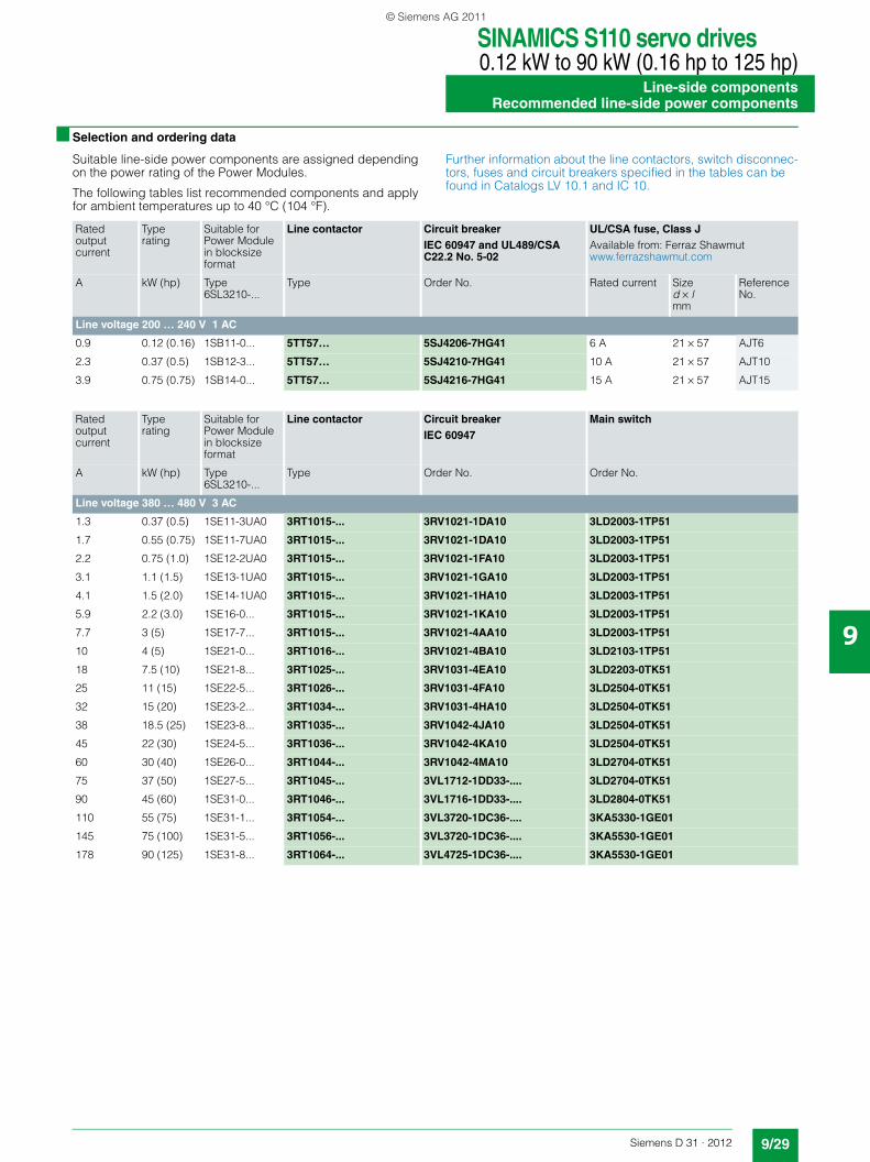
■ Selection and ordering data
Suitable line-side power components are assigned depending on the power rating of the Power Modules.
The following tables list recommended components and apply for ambient temperatures up to 40 °C (104 °F).
Further information about the line contactors, switch disconnec-tors, fuses and circuit breakers specified in the tables can be found in Catalogs LV 10.1 and IC 10.
Rated outputcurrent
Type rating
Suitable for Power Module in blocksize format
Line contactor Circuit breakerIEC 60947 and UL489/CSA C22.2 No. 5-02
UL/CSA fuse, Class JAvailable from: Ferraz Shawmutwww.ferrazshawmut.com
A kW (hp) Type 6SL3210-...
Type Order No. Rated current Sized × lmm
Reference No.
Line voltage 200 … 240 V 1 AC
0.9 0.12 (0.16) 1SB11-0... 5TT57… 5SJ4206-7HG41 6 A 21 × 57 AJT6
2.3 0.37 (0.5) 1SB12-3... 5TT57… 5SJ4210-7HG41 10 A 21 × 57 AJT10
3.9 0.75 (0.75) 1SB14-0... 5TT57… 5SJ4216-7HG41 15 A 21 × 57 AJT15
Rated outputcurrent
Type rating
Suitable for Power Module in blocksize format
Line contactor Circuit breakerIEC 60947
Main switch
A kW (hp) Type 6SL3210-...
Type Order No. Order No.
Line voltage 380 … 480 V 3 AC
1.3 0.37 (0.5) 1SE11-3UA0 3RT1015-... 3RV1021-1DA10 3LD2003-1TP51
1.7 0.55 (0.75) 1SE11-7UA0 3RT1015-... 3RV1021-1DA10 3LD2003-1TP51
2.2 0.75 (1.0) 1SE12-2UA0 3RT1015-... 3RV1021-1FA10 3LD2003-1TP51
3.1 1.1 (1.5) 1SE13-1UA0 3RT1015-... 3RV1021-1GA10 3LD2003-1TP51
4.1 1.5 (2.0) 1SE14-1UA0 3RT1015-... 3RV1021-1HA10 3LD2003-1TP51
5.9 2.2 (3.0) 1SE16-0... 3RT1015-... 3RV1021-1KA10 3LD2003-1TP51
7.7 3 (5) 1SE17-7... 3RT1015-... 3RV1021-4AA10 3LD2003-1TP51
10 4 (5) 1SE21-0... 3RT1016-... 3RV1021-4BA10 3LD2103-1TP51
18 7.5 (10) 1SE21-8... 3RT1025-... 3RV1031-4EA10 3LD2203-0TK51
25 11 (15) 1SE22-5... 3RT1026-... 3RV1031-4FA10 3LD2504-0TK51
32 15 (20) 1SE23-2... 3RT1034-... 3RV1031-4HA10 3LD2504-0TK51
38 18.5 (25) 1SE23-8... 3RT1035-... 3RV1042-4JA10 3LD2504-0TK51
45 22 (30) 1SE24-5... 3RT1036-... 3RV1042-4KA10 3LD2504-0TK51
60 30 (40) 1SE26-0... 3RT1044-... 3RV1042-4MA10 3LD2704-0TK51
75 37 (50) 1SE27-5... 3RT1045-... 3VL1712-1DD33-.... 3LD2704-0TK51
90 45 (60) 1SE31-0... 3RT1046-... 3VL1716-1DD33-.... 3LD2804-0TK51
110 55 (75) 1SE31-1... 3RT1054-... 3VL3720-1DC36-.... 3KA5330-1GE01
145 75 (100) 1SE31-5... 3RT1056-... 3VL3720-1DC36-.... 3KA5530-1GE01
178 90 (125) 1SE31-8... 3RT1064-... 3VL4725-1DC36-.... 3KA5530-1GE01
© Siemens AG 2011
SINAMICS S110 servo drives0.12 kW to 90 kW (0.16 hp to 125 hp)Line-side componentsRecommended line-side power components
9/30 Siemens D 31 · 2012
9
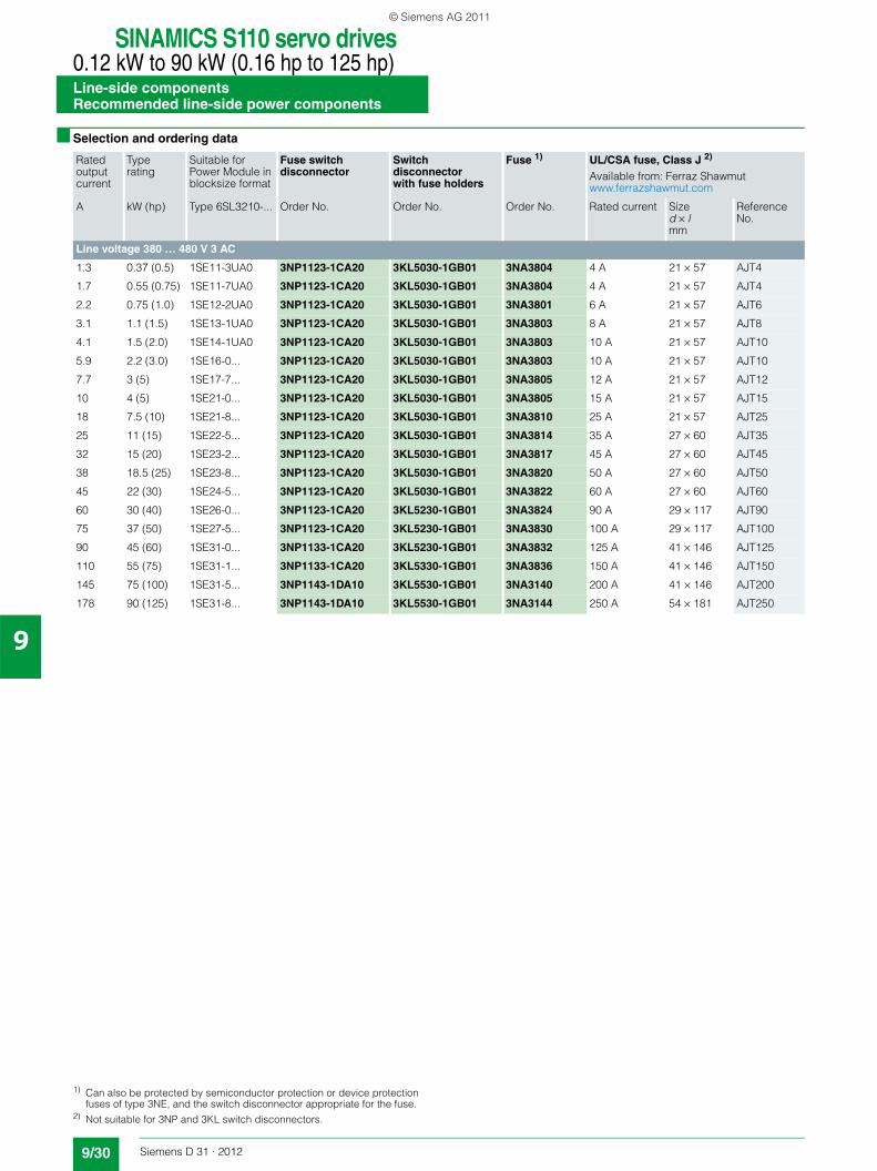
■ Selection and ordering data
Rated outputcurrent
Type rating
Suitable for Power Module in blocksize format
Fuse switch disconnector
Switch disconnector with fuse holders
Fuse 1) UL/CSA fuse, Class J 2)
Available from: Ferraz Shawmutwww.ferrazshawmut.com
A kW (hp) Type 6SL3210-... Order No. Order No. Order No. Rated current Sized × lmm
Reference No.
Line voltage 380 … 480 V 3 AC
1.3 0.37 (0.5) 1SE11-3UA0 3NP1123-1CA20 3KL5030-1GB01 3NA3804 4 A 21 × 57 AJT4
1.7 0.55 (0.75) 1SE11-7UA0 3NP1123-1CA20 3KL5030-1GB01 3NA3804 4 A 21 × 57 AJT4
2.2 0.75 (1.0) 1SE12-2UA0 3NP1123-1CA20 3KL5030-1GB01 3NA3801 6 A 21 × 57 AJT6
3.1 1.1 (1.5) 1SE13-1UA0 3NP1123-1CA20 3KL5030-1GB01 3NA3803 8 A 21 × 57 AJT8
4.1 1.5 (2.0) 1SE14-1UA0 3NP1123-1CA20 3KL5030-1GB01 3NA3803 10 A 21 × 57 AJT10
5.9 2.2 (3.0) 1SE16-0... 3NP1123-1CA20 3KL5030-1GB01 3NA3803 10 A 21 × 57 AJT10
7.7 3 (5) 1SE17-7... 3NP1123-1CA20 3KL5030-1GB01 3NA3805 12 A 21 × 57 AJT12
10 4 (5) 1SE21-0... 3NP1123-1CA20 3KL5030-1GB01 3NA3805 15 A 21 × 57 AJT15
18 7.5 (10) 1SE21-8... 3NP1123-1CA20 3KL5030-1GB01 3NA3810 25 A 21 × 57 AJT25
25 11 (15) 1SE22-5... 3NP1123-1CA20 3KL5030-1GB01 3NA3814 35 A 27 × 60 AJT35
32 15 (20) 1SE23-2... 3NP1123-1CA20 3KL5030-1GB01 3NA3817 45 A 27 × 60 AJT45
38 18.5 (25) 1SE23-8... 3NP1123-1CA20 3KL5030-1GB01 3NA3820 50 A 27 × 60 AJT50
45 22 (30) 1SE24-5... 3NP1123-1CA20 3KL5030-1GB01 3NA3822 60 A 27 × 60 AJT60
60 30 (40) 1SE26-0... 3NP1123-1CA20 3KL5230-1GB01 3NA3824 90 A 29 × 117 AJT90
75 37 (50) 1SE27-5... 3NP1123-1CA20 3KL5230-1GB01 3NA3830 100 A 29 × 117 AJT100
90 45 (60) 1SE31-0... 3NP1133-1CA20 3KL5230-1GB01 3NA3832 125 A 41 × 146 AJT125
110 55 (75) 1SE31-1... 3NP1133-1CA20 3KL5330-1GB01 3NA3836 150 A 41 × 146 AJT150
145 75 (100) 1SE31-5... 3NP1143-1DA10 3KL5530-1GB01 3NA3140 200 A 41 × 146 AJT200
178 90 (125) 1SE31-8... 3NP1143-1DA10 3KL5530-1GB01 3NA3144 250 A 54 × 181 AJT250
1) Can also be protected by semiconductor protection or device protection fuses of type 3NE, and the switch disconnector appropriate for the fuse.
2) Not suitable for 3NP and 3KL switch disconnectors.
© Siemens AG 2011
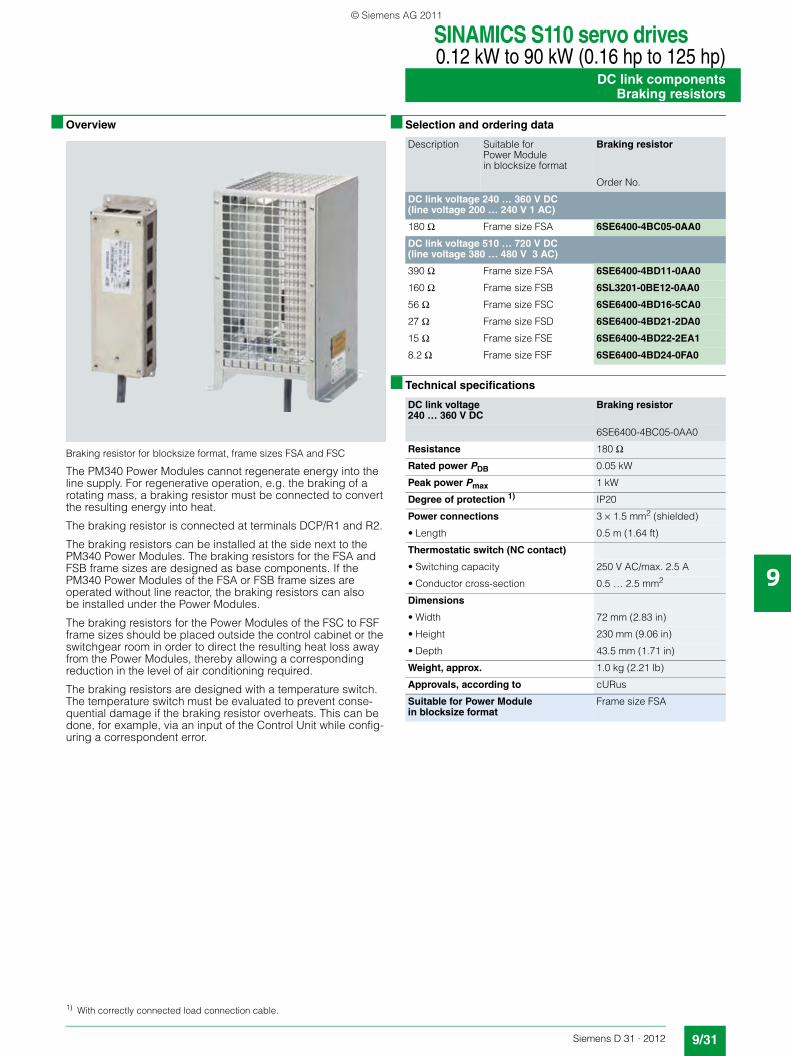
SINAMICS S110 servo drives0.12 kW to 90 kW (0.16 hp to 125 hp)
DC link componentsBraking resistors
9/31Siemens D 31 · 2012
9
■ Overview
Braking resistor for blocksize format, frame sizes FSA and FSC
The PM340 Power Modules cannot regenerate energy into the line supply. For regenerative operation, e.g. the braking of a rotating mass, a braking resistor must be connected to convert the resulting energy into heat.
The braking resistor is connected at terminals DCP/R1 and R2.
The braking resistors can be installed at the side next to the PM340 Power Modules. The braking resistors for the FSA and FSB frame sizes are designed as base components. If the PM340 Power Modules of the FSA or FSB frame sizes are operated without line reactor, the braking resistors can also be installed under the Power Modules.
The braking resistors for the Power Modules of the FSC to FSF frame sizes should be placed outside the control cabinet or the switchgear room in order to direct the resulting heat loss away from the Power Modules, thereby allowing a corresponding reduction in the level of air conditioning required.
The braking resistors are designed with a temperature switch. The temperature switch must be evaluated to prevent conse-quential damage if the braking resistor overheats. This can be done, for example, via an input of the Control Unit while config-uring a correspondent error.
■ Selection and ordering data
■ Technical specifications
Description Suitable for Power Module in blocksize format
Braking resistor
Order No.
DC link voltage 240 … 360 V DC(line voltage 200 … 240 V 1 AC)
180 Ω Frame size FSA 6SE6400-4BC05-0AA0
DC link voltage 510 … 720 V DC(line voltage 380 … 480 V 3 AC)
390 Ω Frame size FSA 6SE6400-4BD11-0AA0
160 Ω Frame size FSB 6SL3201-0BE12-0AA0
56 Ω Frame size FSC 6SE6400-4BD16-5CA0
27 Ω Frame size FSD 6SE6400-4BD21-2DA0
15 Ω Frame size FSE 6SE6400-4BD22-2EA1
8.2 Ω Frame size FSF 6SE6400-4BD24-0FA0
DC link voltage 240 … 360 V DC
Braking resistor
6SE6400-4BC05-0AA0
Resistance 180 Ω
Rated power PDB 0.05 kW
Peak power Pmax 1 kW
Degree of protection 1) IP20
Power connections 3 × 1.5 mm2 (shielded)
• Length 0.5 m (1.64 ft)
Thermostatic switch (NC contact)
• Switching capacity 250 V AC/max. 2.5 A
• Conductor cross-section 0.5 … 2.5 mm2
Dimensions
• Width 72 mm (2.83 in)
• Height 230 mm (9.06 in)
• Depth 43.5 mm (1.71 in)
Weight, approx. 1.0 kg (2.21 lb)
Approvals, according to cURus
Suitable for Power Module in blocksize format
Frame size FSA
1) With correctly connected load connection cable.
© Siemens AG 2011
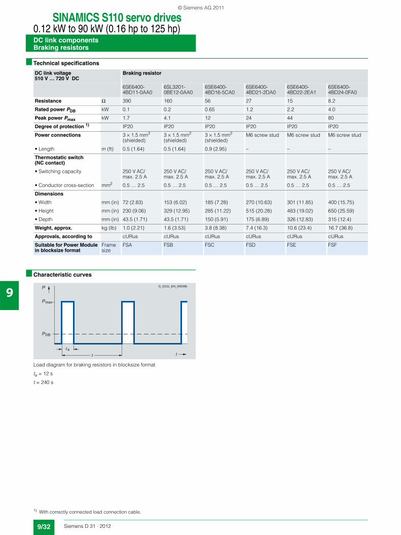
SINAMICS S110 servo drives0.12 kW to 90 kW (0.16 hp to 125 hp)DC link componentsBraking resistors
9/32 Siemens D 31 · 2012
9
■ Technical specifications
■ Characteristic curves
Load diagram for braking resistors in blocksize format
ta = 12 s
t = 240 s
DC link voltage 510 V … 720 V DC
Braking resistor
6SE6400-4BD11-0AA0
6SL3201-0BE12-0AA0
6SE6400-4BD16-5CA0
6SE6400-4BD21-2DA0
6SE6400-4BD22-2EA1
6SE6400-4BD24-0FA0
Resistance Ω 390 160 56 27 15 8.2
Rated power PDB kW 0.1 0.2 0.65 1.2 2.2 4.0
Peak power Pmax kW 1.7 4.1 12 24 44 80
Degree of protection 1) IP20 IP20 IP20 IP20 IP20 IP20
Power connections 3 × 1.5 mm2 (shielded)
3 × 1.5 mm2 (shielded)
3 × 1.5 mm2 (shielded)
M6 screw stud M6 screw stud M6 screw stud
• Length m (ft) 0.5 (1.64) 0.5 (1.64) 0.9 (2.95) – – –
Thermostatic switch (NC contact)
• Switching capacity 250 V AC/max. 2.5 A
250 V AC/max. 2.5 A
250 V AC/max. 2.5 A
250 V AC/max. 2.5 A
250 V AC/max. 2.5 A
250 V AC/max. 2.5 A
• Conductor cross-section mm2 0.5 … 2.5 0.5 … 2.5 0.5 … 2.5 0.5 … 2.5 0.5 … 2.5 0.5 … 2.5
Dimensions
• Width mm (in) 72 (2.83) 153 (6.02) 185 (7.28) 270 (10.63) 301 (11.85) 400 (15.75)
• Height mm (in) 230 (9.06) 329 (12.95) 285 (11.22) 515 (20.28) 483 (19.02) 650 (25.59)
• Depth mm (in) 43.5 (1.71) 43.5 (1.71) 150 (5.91) 175 (6.89) 326 (12.83) 315 (12.4)
Weight, approx. kg (lb) 1.0 (2.21) 1.6 (3.53) 3.8 (8.38) 7.4 (16.3) 10.6 (23.4) 16.7 (36.8)
Approvals, according to cURus cURus cURus cURus cURus cURus
Suitable for Power Module in blocksize format
Frame size
FSA FSB FSC FSD FSE FSF
a
P
P
P
G_D211_EN_00038b
max
DB
1) With correctly connected load connection cable.
© Siemens AG 2011
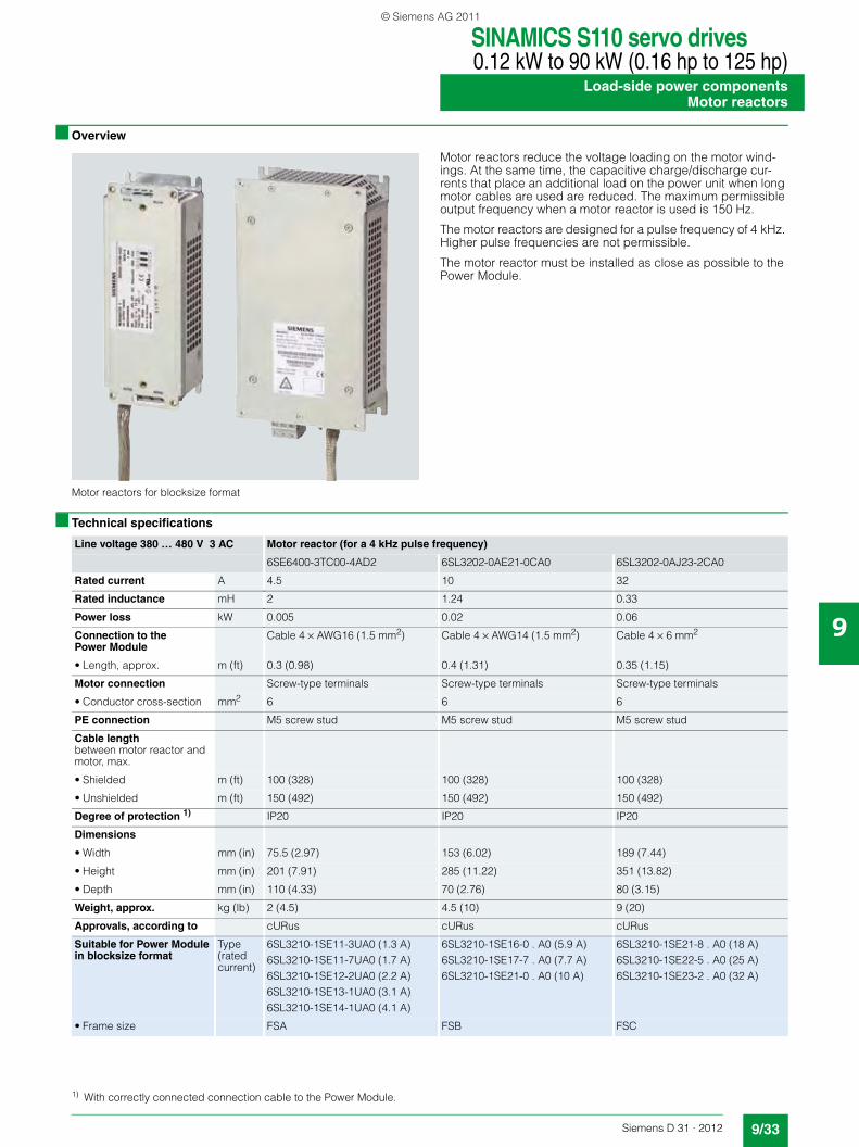
SINAMICS S110 servo drives0.12 kW to 90 kW (0.16 hp to 125 hp)
Load-side power componentsMotor reactors
9/33Siemens D 31 · 2012
9
■ Overview
Motor reactors for blocksize format
Motor reactors reduce the voltage loading on the motor wind-ings. At the same time, the capacitive charge/discharge cur-rents that place an additional load on the power unit when long motor cables are used are reduced. The maximum permissible output frequency when a motor reactor is used is 150 Hz.
The motor reactors are designed for a pulse frequency of 4 kHz. Higher pulse frequencies are not permissible.
The motor reactor must be installed as close as possible to the Power Module.
■ Technical specifications
Line voltage 380 … 480 V 3 AC Motor reactor (for a 4 kHz pulse frequency)
6SE6400-3TC00-4AD2 6SL3202-0AE21-0CA0 6SL3202-0AJ23-2CA0
Rated current A 4.5 10 32
Rated inductance mH 2 1.24 0.33
Power loss kW 0.005 0.02 0.06
Connection to the Power Module
Cable 4 × AWG16 (1.5 mm2) Cable 4 × AWG14 (1.5 mm2) Cable 4 × 6 mm2
• Length, approx. m (ft) 0.3 (0.98) 0.4 (1.31) 0.35 (1.15)
Motor connection Screw-type terminals Screw-type terminals Screw-type terminals
• Conductor cross-section mm2 6 6 6
PE connection M5 screw stud M5 screw stud M5 screw stud
Cable lengthbetween motor reactor and motor, max.
• Shielded m (ft) 100 (328) 100 (328) 100 (328)
• Unshielded m (ft) 150 (492) 150 (492) 150 (492)
Degree of protection 1) IP20 IP20 IP20
Dimensions
• Width mm (in) 75.5 (2.97) 153 (6.02) 189 (7.44)
• Height mm (in) 201 (7.91) 285 (11.22) 351 (13.82)
• Depth mm (in) 110 (4.33) 70 (2.76) 80 (3.15)
Weight, approx. kg (lb) 2 (4.5) 4.5 (10) 9 (20)
Approvals, according to cURus cURus cURus
Suitable for Power Module in blocksize format
Type (rated current)
6SL3210-1SE11-3UA0 (1.3 A)6SL3210-1SE11-7UA0 (1.7 A)6SL3210-1SE12-2UA0 (2.2 A)6SL3210-1SE13-1UA0 (3.1 A)6SL3210-1SE14-1UA0 (4.1 A)
6SL3210-1SE16-0 . A0 (5.9 A)6SL3210-1SE17-7 . A0 (7.7 A)6SL3210-1SE21-0 . A0 (10 A)
6SL3210-1SE21-8 . A0 (18 A)6SL3210-1SE22-5 . A0 (25 A)6SL3210-1SE23-2 . A0 (32 A)
• Frame size FSA FSB FSC
1) With correctly connected connection cable to the Power Module.
© Siemens AG 2011
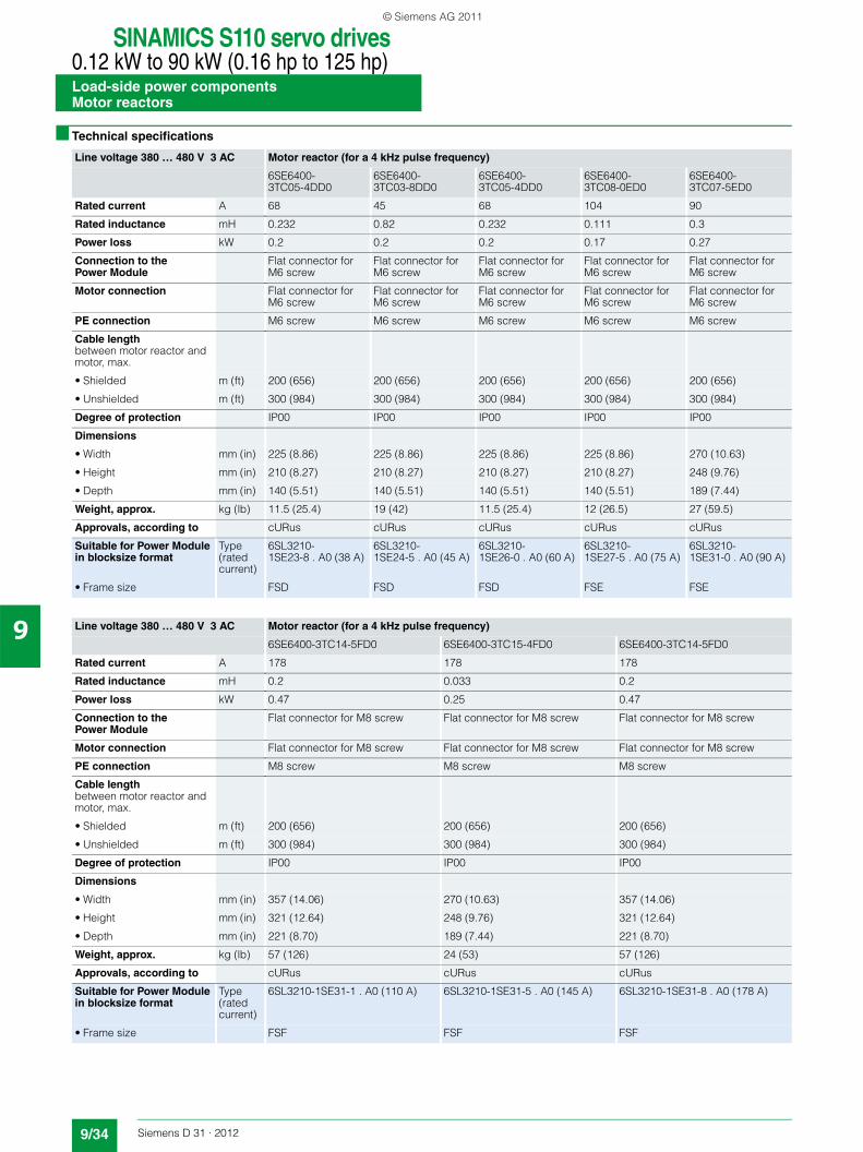
SINAMICS S110 servo drives0.12 kW to 90 kW (0.16 hp to 125 hp)Load-side power componentsMotor reactors
9/34 Siemens D 31 · 2012
9
■ Technical specifications
Line voltage 380 … 480 V 3 AC Motor reactor (for a 4 kHz pulse frequency)
6SE6400-3TC05-4DD0
6SE6400-3TC03-8DD0
6SE6400-3TC05-4DD0
6SE6400-3TC08-0ED0
6SE6400-3TC07-5ED0
Rated current A 68 45 68 104 90
Rated inductance mH 0.232 0.82 0.232 0.111 0.3
Power loss kW 0.2 0.2 0.2 0.17 0.27
Connection to the Power Module
Flat connector for M6 screw
Flat connector for M6 screw
Flat connector for M6 screw
Flat connector for M6 screw
Flat connector for M6 screw
Motor connection Flat connector for M6 screw
Flat connector for M6 screw
Flat connector for M6 screw
Flat connector for M6 screw
Flat connector for M6 screw
PE connection M6 screw M6 screw M6 screw M6 screw M6 screw
Cable lengthbetween motor reactor and motor, max.
• Shielded m (ft) 200 (656) 200 (656) 200 (656) 200 (656) 200 (656)
• Unshielded m (ft) 300 (984) 300 (984) 300 (984) 300 (984) 300 (984)
Degree of protection IP00 IP00 IP00 IP00 IP00
Dimensions
• Width mm (in) 225 (8.86) 225 (8.86) 225 (8.86) 225 (8.86) 270 (10.63)
• Height mm (in) 210 (8.27) 210 (8.27) 210 (8.27) 210 (8.27) 248 (9.76)
• Depth mm (in) 140 (5.51) 140 (5.51) 140 (5.51) 140 (5.51) 189 (7.44)
Weight, approx. kg (lb) 11.5 (25.4) 19 (42) 11.5 (25.4) 12 (26.5) 27 (59.5)
Approvals, according to cURus cURus cURus cURus cURus
Suitable for Power Module in blocksize format
Type (rated current)
6SL3210-1SE23-8 . A0 (38 A)
6SL3210-1SE24-5 . A0 (45 A)
6SL3210-1SE26-0 . A0 (60 A)
6SL3210-1SE27-5 . A0 (75 A)
6SL3210-1SE31-0 . A0 (90 A)
• Frame size FSD FSD FSD FSE FSE
Line voltage 380 … 480 V 3 AC Motor reactor (for a 4 kHz pulse frequency)
6SE6400-3TC14-5FD0 6SE6400-3TC15-4FD0 6SE6400-3TC14-5FD0
Rated current A 178 178 178
Rated inductance mH 0.2 0.033 0.2
Power loss kW 0.47 0.25 0.47
Connection to the Power Module
Flat connector for M8 screw Flat connector for M8 screw Flat connector for M8 screw
Motor connection Flat connector for M8 screw Flat connector for M8 screw Flat connector for M8 screw
PE connection M8 screw M8 screw M8 screw
Cable lengthbetween motor reactor and motor, max.
• Shielded m (ft) 200 (656) 200 (656) 200 (656)
• Unshielded m (ft) 300 (984) 300 (984) 300 (984)
Degree of protection IP00 IP00 IP00
Dimensions
• Width mm (in) 357 (14.06) 270 (10.63) 357 (14.06)
• Height mm (in) 321 (12.64) 248 (9.76) 321 (12.64)
• Depth mm (in) 221 (8.70) 189 (7.44) 221 (8.70)
Weight, approx. kg (lb) 57 (126) 24 (53) 57 (126)
Approvals, according to cURus cURus cURus
Suitable for Power Module in blocksize format
Type (rated current)
6SL3210-1SE31-1 . A0 (110 A) 6SL3210-1SE31-5 . A0 (145 A) 6SL3210-1SE31-8 . A0 (178 A)
• Frame size FSF FSF FSF
© Siemens AG 2011
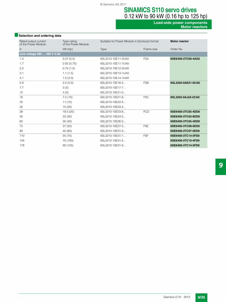
SINAMICS S110 servo drives0.12 kW to 90 kW (0.16 hp to 125 hp)
Load-side power componentsMotor reactors
9/35Siemens D 31 · 2012
9
■ Selection and ordering data
Rated output current of the Power Module
Type rating of the Power Module
Suitable for Power Module in blocksize format Motor reactor
A kW (hp) Type Frame size Order No.
Line voltage 380 … 480 V 3 AC
1.3 0.37 (0.5) 6SL3210-1SE11-3UA0 FSA 6SE6400-3TC00-4AD2
1.7 0.55 (0.75) 6SL3210-1SE11-7UA0
2.2 0.75 (1.0) 6SL3210-1SE12-2UA0
3.1 1.1 (1.5) 6SL3210-1SE13-1UA0
4.1 1.5 (2.0) 6SL3210-1SE14-1UA0
5.9 2.2 (3.0) 6SL3210-1SE16-0... FSB 6SL3202-0AE21-0CA0
7.7 3 (5) 6SL3210-1SE17-7...
10 4 (5) 6SL3210-1SE21-0...
18 7.5 (10) 6SL3210-1SE21-8... FSC 6SL3202-0AJ23-2CA0
25 11 (15) 6SL3210-1SE22-5...
32 15 (20) 6SL3210-1SE23-2...
38 18.5 (25) 6SL3210-1SE23-8... FCD 6SE6400-3TC05-4DD0
45 22 (30) 6SL3210-1SE24-5... 6SE6400-3TC03-8DD0
60 30 (40) 6SL3210-1SE26-0... 6SE6400-3TC05-4DD0
75 37 (50) 6SL3210-1SE27-5... FSE 6SE6400-3TC08-0ED0
90 45 (60) 6SL3210-1SE31-0... 6SE6400-3TC07-5ED0
110 55 (75) 6SL3210-1SE31-1... FSF 6SE6400-3TC14-5FD0
145 75 (100) 6SL3210-1SE31-5... 6SE6400-3TC15-4FD0
178 90 (125) 6SL3210-1SE31-8... 6SE6400-3TC14-5FD0
© Siemens AG 2011
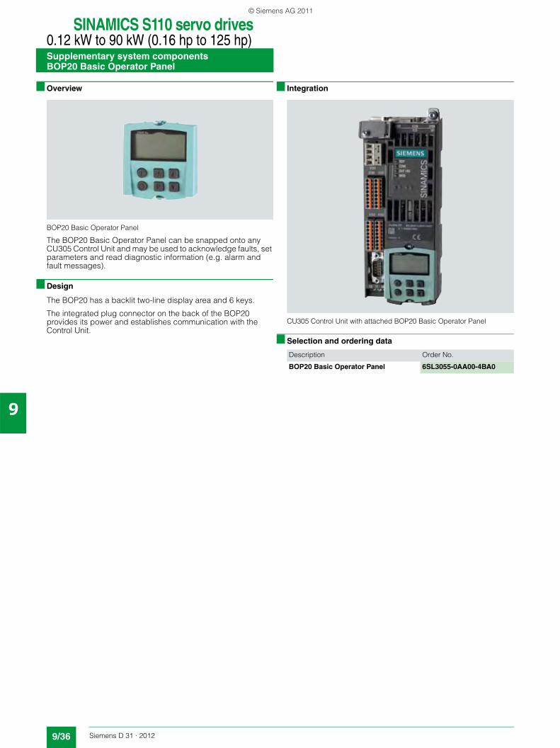
SINAMICS S110 servo drives0.12 kW to 90 kW (0.16 hp to 125 hp)Supplementary system componentsBOP20 Basic Operator Panel
9/36 Siemens D 31 · 2012
9
■ Overview
BOP20 Basic Operator Panel
The BOP20 Basic Operator Panel can be snapped onto any CU305 Control Unit and may be used to acknowledge faults, set parameters and read diagnostic information (e.g. alarm and fault messages).
■ Design
The BOP20 has a backlit two-line display area and 6 keys.
The integrated plug connector on the back of the BOP20 provides its power and establishes communication with the Control Unit.
■ Integration
CU305 Control Unit with attached BOP20 Basic Operator Panel
■ Selection and ordering data
Description Order No.
BOP20 Basic Operator Panel 6SL3055-0AA00-4BA0
© Siemens AG 2011
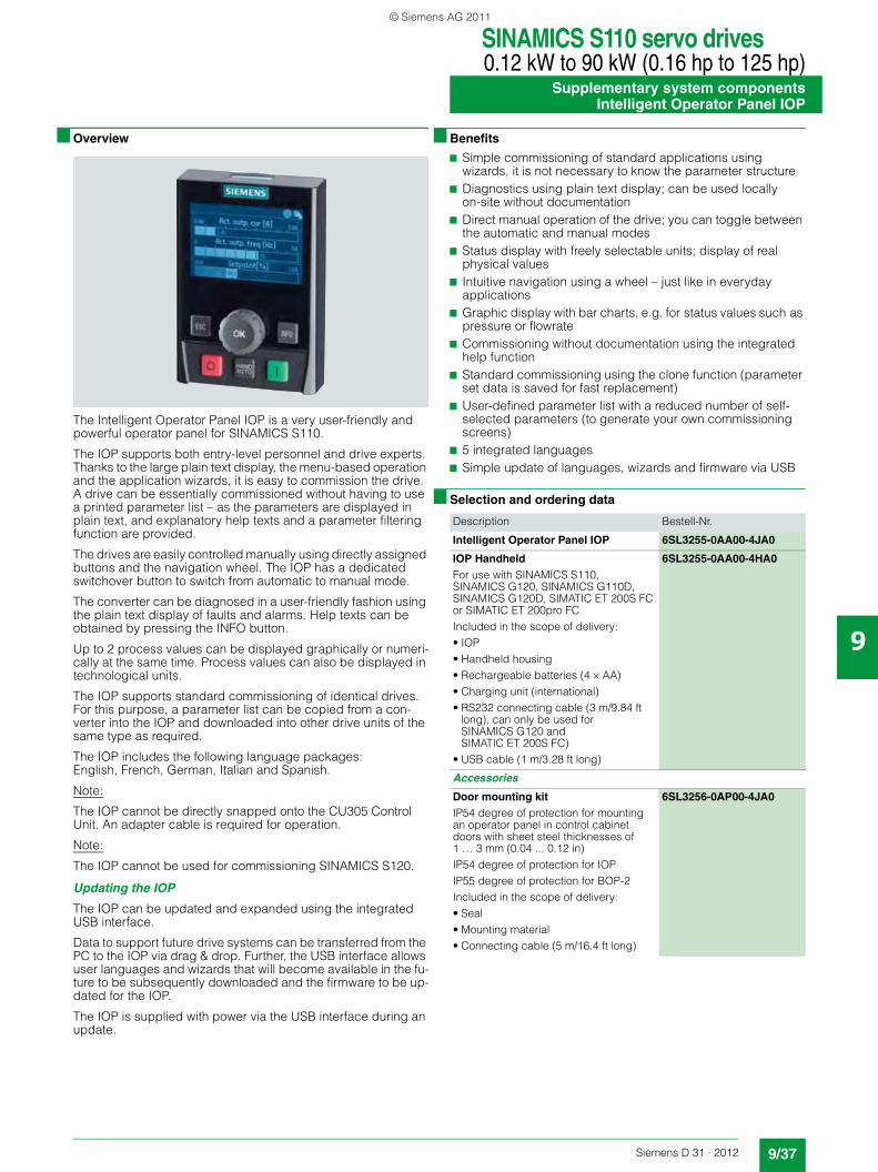
SINAMICS S110 servo drives0.12 kW to 90 kW (0.16 hp to 125 hp)
Supplementary system componentsIntelligent Operator Panel IOP
9/37Siemens D 31 · 2012
9
■ Overview
The Intelligent Operator Panel IOP is a very user-friendly and powerful operator panel for SINAMICS S110.
The IOP supports both entry-level personnel and drive experts. Thanks to the large plain text display, the menu-based operation and the application wizards, it is easy to commission the drive. A drive can be essentially commissioned without having to use a printed parameter list – as the parameters are displayed in plain text, and explanatory help texts and a parameter filtering function are provided.
The drives are easily controlled manually using directly assigned buttons and the navigation wheel. The IOP has a dedicated switchover button to switch from automatic to manual mode.
The converter can be diagnosed in a user-friendly fashion using the plain text display of faults and alarms. Help texts can be obtained by pressing the INFO button.
Up to 2 process values can be displayed graphically or numeri-cally at the same time. Process values can also be displayed in technological units.
The IOP supports standard commissioning of identical drives. For this purpose, a parameter list can be copied from a con-verter into the IOP and downloaded into other drive units of the same type as required.
The IOP includes the following language packages: English, French, German, Italian and Spanish.
Note:
The IOP cannot be directly snapped onto the CU305 Control Unit. An adapter cable is required for operation.
Note:
The IOP cannot be used for commissioning SINAMICS S120.
Updating the IOP
The IOP can be updated and expanded using the integrated USB interface.
Data to support future drive systems can be transferred from the PC to the IOP via drag & drop. Further, the USB interface allows user languages and wizards that will become available in the fu-ture to be subsequently downloaded and the firmware to be up-dated for the IOP.
The IOP is supplied with power via the USB interface during an update.
■ Benefits
7 Simple commissioning of standard applications using wizards, it is not necessary to know the parameter structure
7 Diagnostics using plain text display; can be used locally on-site without documentation
7 Direct manual operation of the drive; you can toggle between the automatic and manual modes
7 Status display with freely selectable units; display of real physical values
7 Intuitive navigation using a wheel – just like in everyday applications
7 Graphic display with bar charts, e.g. for status values such as pressure or flowrate
7 Commissioning without documentation using the integrated help function
7 Standard commissioning using the clone function (parameter set data is saved for fast replacement)
7 User-defined parameter list with a reduced number of self-selected parameters (to generate your own commissioning screens)
7 5 integrated languages7 Simple update of languages, wizards and firmware via USB
■ Selection and ordering data
Description Bestell-Nr.
Intelligent Operator Panel IOP 6SL3255-0AA00-4JA0
IOP HandheldFor use with SINAMICS S110, SINAMICS G120, SINAMICS G110D, SINAMICS G120D, SIMATIC ET 200S FC or SIMATIC ET 200pro FCIncluded in the scope of delivery:• IOP• Handheld housing• Rechargeable batteries (4 × AA)• Charging unit (international)• RS232 connecting cable (3 m/9.84 ft
long), can only be used for SINAMICS G120 and SIMATIC ET 200S FC)
• USB cable (1 m/3.28 ft long)
6SL3255-0AA00-4HA0
Accessories
Door mounting kitIP54 degree of protection for mounting an operator panel in control cabinet doors with sheet steel thicknesses of 1 … 3 mm (0.04 ... 0.12 in)IP54 degree of protection for IOPIP55 degree of protection for BOP-2Included in the scope of delivery:• Seal• Mounting material• Connecting cable (5 m/16.4 ft long)
6SL3256-0AP00-4JA0
© Siemens AG 2011
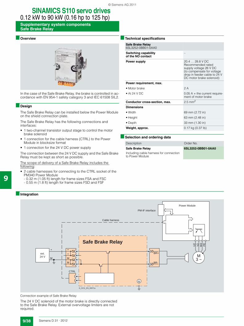
SINAMICS S110 servo drives0.12 kW to 90 kW (0.16 hp to 125 hp)Supplementary system componentsSafe Brake Relay
9/38 Siemens D 31 · 2012
9
■ Overview
In the case of the Safe Brake Relay, the brake is controlled in ac-cordance with EN 954-1 safety category 3 and IEC 61508 SIL2.
■ Design
The Safe Brake Relay can be installed below the Power Module on the shield connection plate.
The Safe Brake Relay has the following connections and interfaces:• 1 two-channel transistor output stage to control the motor
brake solenoid• 1 connection for the cable harness (CTRL) to the Power
Module in blocksize format• 1 connection for the 24 V DC power supply
The connection between the 24 V DC supply and the Safe Brake Relay must be kept as short as possible.
The scope of delivery of a Safe Brake Relay includes the following:• 2 cable harnesses for connecting to the CTRL socket of the
PM340 Power Module - 0.32 m (1.05 ft) length for frame sizes FSA and FSC- 0.55 m (1.8 ft) length for frame sizes FSD and FSF
■ Technical specifications
■ Selection and ordering data
■ Integration
Connection example of Safe Brake Relay
The 24 V DC solenoid of the motor brake is directly connected to the Safe Brake Relay. External overvoltage limiters are not required.
Safe Brake Relay6SL3252-0BB01-0AA0
Switching capabilityof the NO contact
–
Power supply 20.4 … 28.8 V DCRecommended rated supply voltage 26 V DC(to compensate for voltage drop in feeder cable to 24 V DC motor brake solenoid)
Power requirement, max.
• Motor brake 2 A
• At 24 V DC 0.05 A + the current require-ment of motor brake
Conductor cross-section, max. 2.5 mm2
Dimensions
• Width 69 mm (2.72 in)
• Height 63 mm (2.48 in)
• Depth 33 mm (1.30 in)
Weight, approx. 0.17 kg (0.37 lb)
Description Order No.
Safe Brake RelayIncluding cable harness for connection to Power Module
6SL3252-0BB01-0AA0
U2
V2
W2
PE
M3 ~
Safe Brake Relay
CTRL
M
+M
+
M
+
BR-
BR+
G_D211_EN_00071a
ext.24 V
PM-IF interface
Cable harness
Power Module
© Siemens AG 2011
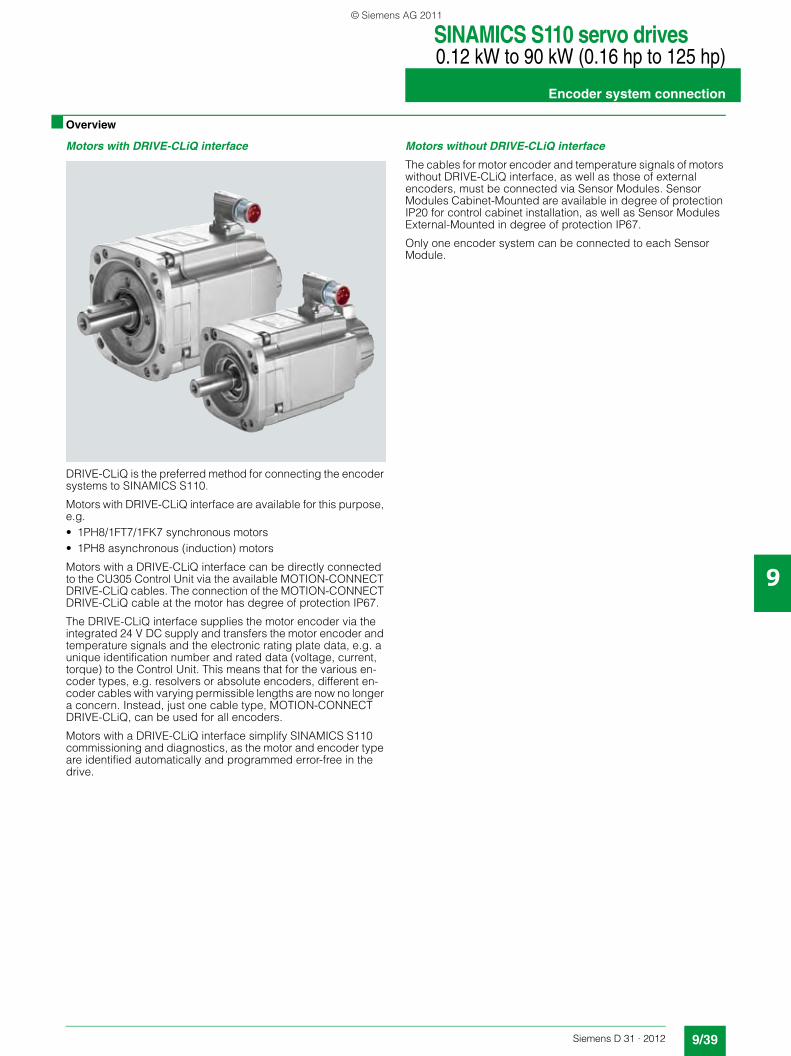
SINAMICS S110 servo drives0.12 kW to 90 kW (0.16 hp to 125 hp)
Encoder system connection
9/39Siemens D 31 · 2012
9
■ Overview
Motors with DRIVE-CLiQ interface
DRIVE-CLiQ is the preferred method for connecting the encoder systems to SINAMICS S110.
Motors with DRIVE-CLiQ interface are available for this purpose, e.g.• 1PH8/1FT7/1FK7 synchronous motors• 1PH8 asynchronous (induction) motors
Motors with a DRIVE-CLiQ interface can be directly connected to the CU305 Control Unit via the available MOTION-CONNECT DRIVE-CLiQ cables. The connection of the MOTION-CONNECT DRIVE-CLiQ cable at the motor has degree of protection IP67.
The DRIVE-CLiQ interface supplies the motor encoder via the integrated 24 V DC supply and transfers the motor encoder and temperature signals and the electronic rating plate data, e.g. a unique identification number and rated data (voltage, current, torque) to the Control Unit. This means that for the various en-coder types, e.g. resolvers or absolute encoders, different en-coder cables with varying permissible lengths are now no longer a concern. Instead, just one cable type, MOTION-CONNECT DRIVE-CLiQ, can be used for all encoders.
Motors with a DRIVE-CLiQ interface simplify SINAMICS S110 commissioning and diagnostics, as the motor and encoder type are identified automatically and programmed error-free in the drive.
Motors without DRIVE-CLiQ interface
The cables for motor encoder and temperature signals of motors without DRIVE-CLiQ interface, as well as those of external encoders, must be connected via Sensor Modules. Sensor Modules Cabinet-Mounted are available in degree of protection IP20 for control cabinet installation, as well as Sensor Modules External-Mounted in degree of protection IP67.
Only one encoder system can be connected to each Sensor Module.
© Siemens AG 2011
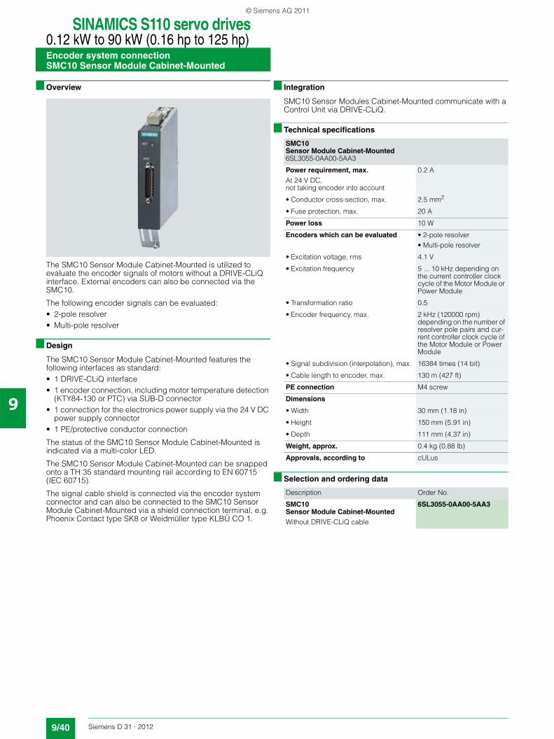
SINAMICS S110 servo drives0.12 kW to 90 kW (0.16 hp to 125 hp)Encoder system connectionSMC10 Sensor Module Cabinet-Mounted
9/40 Siemens D 31 · 2012
9
■ Overview
The SMC10 Sensor Module Cabinet-Mounted is utilized to evaluate the encoder signals of motors without a DRIVE-CLiQ interface. External encoders can also be connected via the SMC10.
The following encoder signals can be evaluated:• 2-pole resolver• Multi-pole resolver
■ Design
The SMC10 Sensor Module Cabinet-Mounted features the following interfaces as standard:• 1 DRIVE-CLiQ interface• 1 encoder connection, including motor temperature detection
(KTY84-130 or PTC) via SUB-D connector• 1 connection for the electronics power supply via the 24 V DC
power supply connector• 1 PE/protective conductor connection
The status of the SMC10 Sensor Module Cabinet-Mounted is indicated via a multi-color LED.
The SMC10 Sensor Module Cabinet-Mounted can be snapped onto a TH 35 standard mounting rail according to EN 60715 (IEC 60715).
The signal cable shield is connected via the encoder system connector and can also be connected to the SMC10 Sensor Module Cabinet-Mounted via a shield connection terminal, e.g. Phoenix Contact type SK8 or Weidmüller type KLBÜ CO 1.
■ Integration
SMC10 Sensor Modules Cabinet-Mounted communicate with a Control Unit via DRIVE-CLiQ.
■ Technical specifications
■ Selection and ordering data
SMC10 Sensor Module Cabinet-Mounted 6SL3055-0AA00-5AA3
Power requirement, max.At 24 V DC,not taking encoder into account
0.2 A
• Conductor cross-section, max. 2.5 mm2
• Fuse protection, max. 20 A
Power loss 10 W
Encoders which can be evaluated • 2-pole resolver• Multi-pole resolver
• Excitation voltage, rms 4.1 V
• Excitation frequency 5 ... 10 kHz depending on the current controller clock cycle of the Motor Module or Power Module
• Transformation ratio 0.5
• Encoder frequency, max. 2 kHz (120000 rpm) depending on the number of resolver pole pairs and cur-rent controller clock cycle of the Motor Module or Power Module
• Signal subdivision (interpolation), max. 16384 times (14 bit)
• Cable length to encoder, max. 130 m (427 ft)
PE connection M4 screw
Dimensions
• Width 30 mm (1.18 in)
• Height 150 mm (5.91 in)
• Depth 111 mm (4.37 in)
Weight, approx. 0.4 kg (0.88 lb)
Approvals, according to cULus
Description Order No.
SMC10Sensor Module Cabinet-Mounted Without DRIVE-CLiQ cable
6SL3055-0AA00-5AA3
© Siemens AG 2011
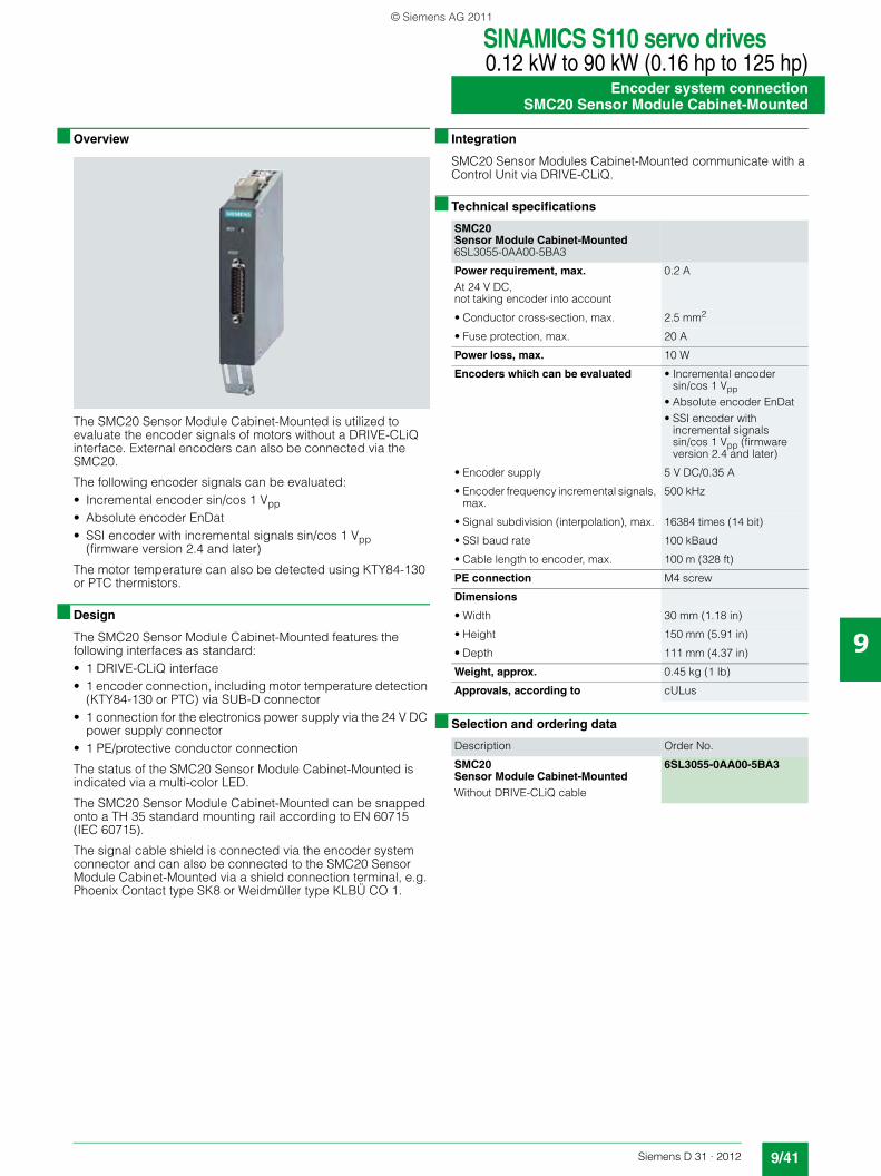
SINAMICS S110 servo drives0.12 kW to 90 kW (0.16 hp to 125 hp)
Encoder system connectionSMC20 Sensor Module Cabinet-Mounted
9/41Siemens D 31 · 2012
9
■ Overview
The SMC20 Sensor Module Cabinet-Mounted is utilized to evaluate the encoder signals of motors without a DRIVE-CLiQ interface. External encoders can also be connected via the SMC20.
The following encoder signals can be evaluated:• Incremental encoder sin/cos 1 Vpp• Absolute encoder EnDat• SSI encoder with incremental signals sin/cos 1 Vpp
(firmware version 2.4 and later)
The motor temperature can also be detected using KTY84-130 or PTC thermistors.
■ Design
The SMC20 Sensor Module Cabinet-Mounted features the following interfaces as standard:• 1 DRIVE-CLiQ interface• 1 encoder connection, including motor temperature detection
(KTY84-130 or PTC) via SUB-D connector• 1 connection for the electronics power supply via the 24 V DC
power supply connector• 1 PE/protective conductor connection
The status of the SMC20 Sensor Module Cabinet-Mounted is indicated via a multi-color LED.
The SMC20 Sensor Module Cabinet-Mounted can be snapped onto a TH 35 standard mounting rail according to EN 60715 (IEC 60715).
The signal cable shield is connected via the encoder system connector and can also be connected to the SMC20 Sensor Module Cabinet-Mounted via a shield connection terminal, e.g. Phoenix Contact type SK8 or Weidmüller type KLBÜ CO 1.
■ Integration
SMC20 Sensor Modules Cabinet-Mounted communicate with a Control Unit via DRIVE-CLiQ.
■ Technical specifications
■ Selection and ordering data
SMC20Sensor Module Cabinet-Mounted 6SL3055-0AA00-5BA3
Power requirement, max.At 24 V DC,not taking encoder into account
0.2 A
• Conductor cross-section, max. 2.5 mm2
• Fuse protection, max. 20 A
Power loss, max. 10 W
Encoders which can be evaluated • Incremental encoder sin/cos 1 Vpp
• Absolute encoder EnDat• SSI encoder with
incremental signals sin/cos 1 Vpp (firmware version 2.4 and later)
• Encoder supply 5 V DC/0.35 A
• Encoder frequency incremental signals, max.
500 kHz
• Signal subdivision (interpolation), max. 16384 times (14 bit)
• SSI baud rate 100 kBaud
• Cable length to encoder, max. 100 m (328 ft)
PE connection M4 screw
Dimensions
• Width 30 mm (1.18 in)
• Height 150 mm (5.91 in)
• Depth 111 mm (4.37 in)
Weight, approx. 0.45 kg (1 lb)
Approvals, according to cULus
Description Order No.
SMC20 Sensor Module Cabinet-Mounted Without DRIVE-CLiQ cable
6SL3055-0AA00-5BA3
© Siemens AG 2011
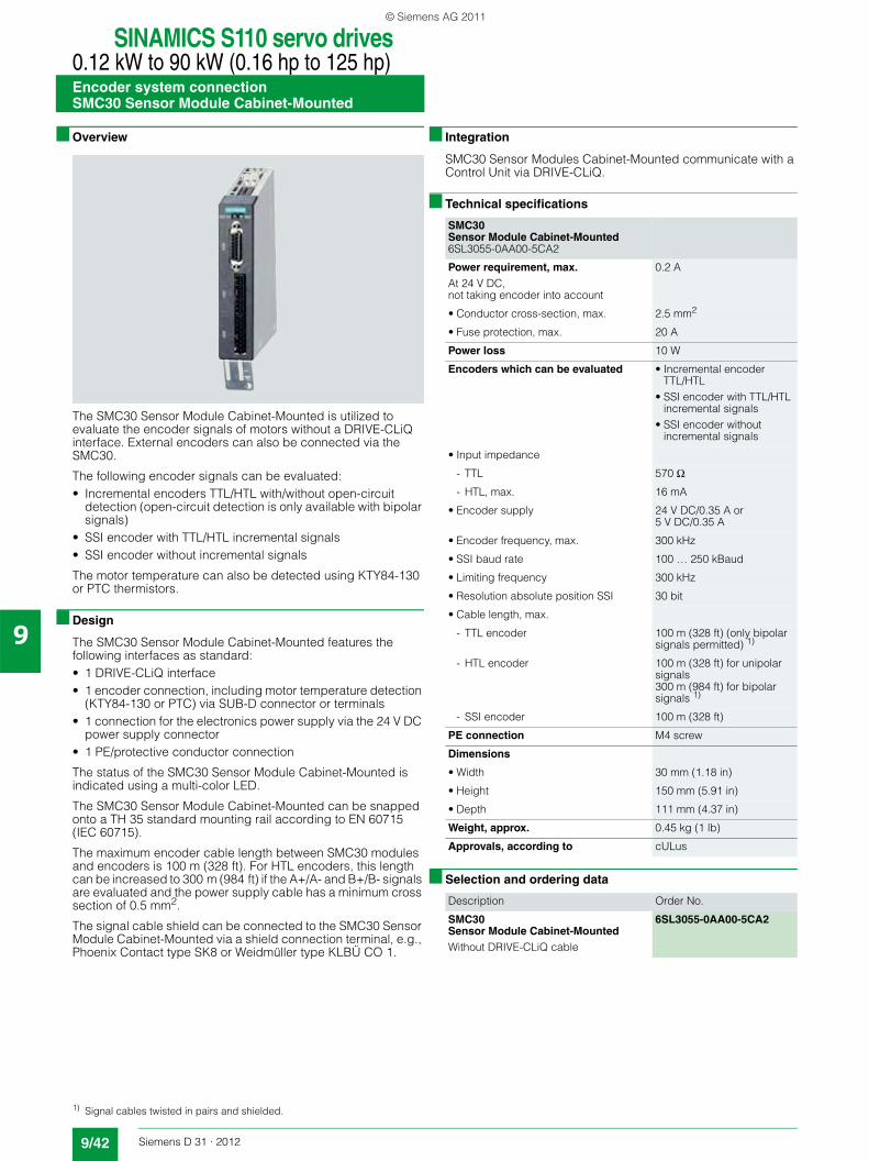
SINAMICS S110 servo drives0.12 kW to 90 kW (0.16 hp to 125 hp)Encoder system connectionSMC30 Sensor Module Cabinet-Mounted
9/42 Siemens D 31 · 2012
9
■ Overview
The SMC30 Sensor Module Cabinet-Mounted is utilized to evaluate the encoder signals of motors without a DRIVE-CLiQ interface. External encoders can also be connected via the SMC30.
The following encoder signals can be evaluated:• Incremental encoders TTL/HTL with/without open-circuit
detection (open-circuit detection is only available with bipolar signals)
• SSI encoder with TTL/HTL incremental signals• SSI encoder without incremental signals
The motor temperature can also be detected using KTY84-130 or PTC thermistors.
■ Design
The SMC30 Sensor Module Cabinet-Mounted features the following interfaces as standard:• 1 DRIVE-CLiQ interface• 1 encoder connection, including motor temperature detection
(KTY84-130 or PTC) via SUB-D connector or terminals• 1 connection for the electronics power supply via the 24 V DC
power supply connector• 1 PE/protective conductor connection
The status of the SMC30 Sensor Module Cabinet-Mounted is indicated using a multi-color LED.
The SMC30 Sensor Module Cabinet-Mounted can be snapped onto a TH 35 standard mounting rail according to EN 60715 (IEC 60715).
The maximum encoder cable length between SMC30 modules and encoders is 100 m (328 ft). For HTL encoders, this length can be increased to 300 m (984 ft) if the A+/A- and B+/B- signals are evaluated and the power supply cable has a minimum cross section of 0.5 mm2.
The signal cable shield can be connected to the SMC30 Sensor Module Cabinet-Mounted via a shield connection terminal, e.g., Phoenix Contact type SK8 or Weidmüller type KLBÜ CO 1.
■ Integration
SMC30 Sensor Modules Cabinet-Mounted communicate with a Control Unit via DRIVE-CLiQ.
■ Technical specifications
■ Selection and ordering data
SMC30Sensor Module Cabinet-Mounted 6SL3055-0AA00-5CA2
Power requirement, max.At 24 V DC,not taking encoder into account
0.2 A
• Conductor cross-section, max. 2.5 mm2
• Fuse protection, max. 20 A
Power loss 10 W
Encoders which can be evaluated • Incremental encoder TTL/HTL
• SSI encoder with TTL/HTL incremental signals
• SSI encoder without incremental signals
• Input impedance
- TTL 570 Ω
- HTL, max. 16 mA
• Encoder supply 24 V DC/0.35 A or 5 V DC/0.35 A
• Encoder frequency, max. 300 kHz
• SSI baud rate 100 … 250 kBaud
• Limiting frequency 300 kHz
• Resolution absolute position SSI 30 bit
• Cable length, max.
- TTL encoder 100 m (328 ft) (only bipolar signals permitted) 1)
- HTL encoder 100 m (328 ft) for unipolar signals300 m (984 ft) for bipolar signals 1)
- SSI encoder 100 m (328 ft)
PE connection M4 screw
Dimensions
• Width 30 mm (1.18 in)
• Height 150 mm (5.91 in)
• Depth 111 mm (4.37 in)
Weight, approx. 0.45 kg (1 lb)
Approvals, according to cULus
Description Order No.
SMC30Sensor Module Cabinet-MountedWithout DRIVE-CLiQ cable
6SL3055-0AA00-5CA2
1) Signal cables twisted in pairs and shielded.
© Siemens AG 2011
Recommended


![Lenovo S110 [BM5138 1.3]](https://img.pdfslide.us/doc/110x75/55cf995a550346d0339cefd3/lenovo-s110-bm5138-13.jpg)