Switch Disconnectors with FusesSENTRON 3KL Switch Disconnectors with Fuses up to 800 A
General data
17/38 Siemens LV 1 · 2010
17
■ Overview
All switch disconnectors feature double contact interruption and an isolating distance. As a result, the fuses of the switch discon-nectors are de-energized in the OFF position.Generally, all 3K. 5 switch disconnectors can be secured on the shaft with a padlock to prevent unauthorized reclosing.
Identical accessories for 3KA switch disconnectors and for 3KL and 3KM switch disconnectors with fuses simplify stock keep-ing. Please inquire about a special variant with reduced values that is particularly resistant to atmospheres high in sulfur, e. g. in the paper and cellulose processing industries.
■ Application
3KL switch disconnectors with fuses protect against overload and short-circuits as main and EMERGENCY-STOP switches of switch boards, distribution boards, power supply and motor out-going feeders. In conjunction with Siemens SITOR semiconduc-tor fuses, they are also used in UPS systems, frequency convert-ers and capacitor control systems.
All 3K switch disconnectors are climate-proof and meet the requirements of IEC 60947-1, IEC 60947-3 and VDE 0660 Part 107.
6
5
7
7
3
1
9
8
4
3
7
9
2
3KL or 3KM basic devicePlug-in contact strip for 3KM
Fuses, optionally BS-88 or LV HRC fuses
Coupling driver with extension shaft
Single-pole terminal cover from 63 A to 630 A, IP20 (vertical to operator side)
Terminal cover, IP20 (vertical to operator side)
Standard products from the Siemens 3SB1 range are used as auxiliary switches.
8UC9 knob for fixed mounting in standard version (black) or EMERGENCY-STOP version (red), or
All components from the switch to the actuator are provided with non-interchangeability features.
8UC7 door-coupling rotary operating mechanism in standard version (ti-grey) or EMERGENCY-STOP version (red/yellow)
Optional
NS
E0_
0155
7b
LV1_17.book Seite 38 Mittwoch, 16. Dezember 2009 4:15 16
© Siemens AG 2010
Switch Disconnectors with FusesSENTRON 3KL Switch Disconnectors with Fuses up to 800 A
General data
17/39Siemens LV 1 · 2010
17
■ More information
1) Technical specifications for approval on request.2) Configuring note: Max. permissible operating temperature for fuse blades
135 °C, for connections 100 °C.3) 110 V (one conducting path).4) With 3KL61 for operation -25 °C ... +35 °C, at +55 °C: Ith = 570 A.5) With 3ND1 switchgear protection fuse.6) AC-23B7) 220 V DC (L1 and L3 series-connected) or 110 V DC
(one conducting path) at DC-23A.8) At 440 V L/R = 4 ms, at 220 V L/R = 15 ms.9) Only DC-22A (L/R = 2.5 ms)10)At 440 V DC-22A, at 220 V DC-23A.
Note:
For the 3KL switch disconnectors, complete kits for standard and EMERGENCY-STOP application are available for installation in the side and rear panels of control cabinets.
Standards IEC 60947-1, IEC 60947-3, VDE 0660 Part 107
Type 3KL50 3KL521) 3KL531) 3KL551) 3KL571) 3KL611) 3KL621)
Rated uninterrupted current Iu A 63 125 160 250 400 630 800For fuse links acc. to DIN 43620, (when SITOR semiconductor fuses are used, a reduction of rated current is necessary, see Catalog Add-On ET B1 AO · 2009)
Size 00 and 000
00 and 000
00 and 000
1 and 2 1 and 2 3 and 2 3 and 2
Conventional free-air thermal current Ith2) A 63 125 160 250 400 630 800
Rated insulation voltage Ui V 690 1000 1000 1000 1000 1000 1000
Rated impulse voltage Uimp kV 6 8 8 8 8 8 8
Rated operational voltage UeAC 50 Hz/60 Hz V 690DC V 440 (3 conducting paths series-connected)
220 (2 conducting paths series-connected) 3)
Rated short-circuit making capacity with fusesPeak value, at 50 Hz/60 Hz 690 V AC
kA 220 220 220 176 176 105 105
Rated conditional short-circuit current with fuses kA 100 100 100 80 80 50 50
Rms value, at AC 50 Hz/60 Hz 690 V
Max. rated current In of the fuses A 80 160 160 400 400 6304) 800
Max. permissible power loss of the installed fuse• NH W 6 9 11.5 32 45 48 62• BS W 8 (A2/A3) 11.5 (A4) 11.5 32 45 48 60.5
Permissible let-through current of the fuses kA 8 17 17 305) 305) 50 50
Maximum permissible let-through I2t value kA2s 55 223 223 1000 1000 5400 10500
Switching capacity (infeed from the top or bottom)
At 400 V AC• Breaking current Ic (at p.f. = 0.35, rms value) A 500 1000 1280 2000 3200 5100 6400• Rated operational current Ie with AC-21A, AC-22A, AC-23A A 63 125 160 250 400 6306) 8006)
• Motor switching capacity AC-23A kW 30 65 80 132 200 335 400
At 500 V AC• Breaking current Ic (at p.f. = 0.35, rms value) A 500 1000 1280 2000 3200 5100 6400• Rated operational current Ie with AC-21A, AC-22A, AC-23A A 63 125 160 250 400 6306) 8006)
• Motor switching capacity AC-23A kW 40 90 110 185 280 425 500
At 690 V AC• Breaking current Ic (at p.f. = 0.35, rms value) A 500 1000 1280 2000 3200 5100 6400• Rated operational current Ie with AC-21A, AC-22A, AC-23A A 63 125 160 250 400 6305) 8005)
• Motor switching capacity AC-23A kW 50 110 150 220 375 560 700
At 440 V DC (3 conducting paths series-connected)7)
• Breaking current Ic (L/R = 15 ms) A 250 500 640 10008) 1600 25209) 25209)
• Rated operational current Ie at DC-23A A 63 125 160 25010) 400 63010) 63010)
Rated short-time current Icw (1 s current, rms value) kA 2.5 3.2 3.2 8 11 32 32
Permissible ambient temperature °C -25 ... +55 for operation4),°C -50 ... +80 when stored
Mechanical endurance, operating cycles 15000 15000 15000 12000 12000 3000 3000
Degree of protection IP00/IP20 (from the operator side, with fuse and terminal covers)
Power loss of the switch disconnector at Ith W 8.5 22 36 33 86 140 225(plus power loss of the fuses)
Main conductor connectionsBusbar systems, max. dimensions (w x t) mm 25 x 9 45 x 10 45 x 10 40 x 12 40 x 15 40 x 17 40 x 17
Cable lug, max. conductor cross-section (stranded) mm2 35 70 120 150 2 x 150 or 1 x 240
2 x 240 2 x 240
Tightening torque Nm 6 ... 7.5 7 ... 10 18 ... 22 35 ... 45 35 ... 45 56 56Terminal screws M6 M6 M8 M10 M10 M12 M12
Protective conductor connectionsFlat bars mm -- -- -- 20 x 2.5 20 x 2.5 -- --Cable lug, max. conductor cross-section (stranded) mm2 -- -- -- 70 120 -- --
LV1_17.book Seite 39 Mittwoch, 16. Dezember 2009 4:15 16
© Siemens AG 2010

Switch Disconnectors with FusesSENTRON 3KL Switch Disconnectors with Fuses up to 800 A
Floor mounting
17/40 Siemens LV 1 · 2010* You can order this quantity or a multiple thereof.
17
■ Selection and ordering data
All switch disconnectors with degree of protection IP00Conductor connecting screws and fuse partitions are generally included in the scope of supply
Fuse monitoring through 5TT3 170 safety monitor with a floating 1 NO, signaling contact, see Catalog ET B1.
For footnotes, see page 17/41.
Rated uninterrupted current Iu
LV HRC fuse links1)
acc. to DIN 436202)DT Order No. Price
per PUPU
(UNIT,SET,
M)
PS* PG Weightper PU
approx.
Size Operational class
A kgComplete versions with 8UC7 door-coupling rotary operating mechanism (black handle)
3-pole for NH fuse systems
63 00 and 000 gG, aM B 3KL50 30-1GB01 1 1 unit 103 1.460125 00 and 000 gG, aM B 3KL52 30-1GB01 1 1 unit 103 2.414160 00 and 000 gG, aM B 3KL53 30-1GB01 1 1 unit 103 2.600250 1 and 2 gG, aM B 3KL55 30-1GB01 1 1 unit 103 6.112
400 2 and 1 gG, aM B 3KL57 30-1GB01 1 1 unit 103 6.067630 3 and 2 gG, aM B 3KL61 30-1GB00 1 1 unit 103 18.0706303) 3 and 23) gG, aM3) D 3KL61 30-1GB02 1 1 unit 113 15.2008003) 3 and 23) gG, aM3) C 3KL62 30-1GB02 1 1 unit 113 15.200
4-pole for NH fuse systems
63 00 and 000 gG, aM B 3KL50 40-1GB01 1 1 unit 103 2.542125 00 and 000 gG, aM B 3KL52 40-1GB01 1 1 unit 103 2.623160 00 and 000 gG, aM C 3KL53 40-1GB01 1 1 unit 103 2.776
250 1 and 2 gG, aM B 3KL55 40-1GB01 1 1 unit 103 6.642400 2 and 1 gG, aM B 3KL57 40-1GB01 1 1 unit 103 6.886630 3 and 2 gG, aM B 3KL61 40-1GB00 1 1 unit 103 16.690
3-pole for fuses acc. to BS 88
63 Form A2/A3 B 3KL50 30-1GG01 1 1 unit 103 1.455125 Form A2/A3 B 3KL52 30-1GG01 1 1 unit 103 2.360
125 Form A4 B 3KL52 30-1GJ01 1 1 unit 103 2.406160 Form A4 B 3KL53 30-1GJ01 1 1 unit 103 2.575
250 Form B1-B3 B 3KL55 30-1GG01 1 1 unit 103 6.115400 Form B1-B3 B 3KL57 30-1GG01 1 1 unit 103 6.582
630 Form C1-C3 C 3KL61 30-1GG00 1 1 unit 103 16.278800 Form C1-C3 D 3KL62 30-1GG00 1 1 unit 113 15.400
4-pole for fuses acc. to BS 88
63 Form A2/A3 B 3KL50 40-1GG01 1 1 unit 103 2.563125 Form A2/A3 B 3KL52 40-1GG01 1 1 unit 103 2.560
125 Form A4 B 3KL52 40-1GJ01 1 1 unit 103 2.614160 Form A4 B 3KL53 40-1GJ01 1 1 unit 103 2.780
250 Form B1-B3 B 3KL55 40-1GG01 1 1 unit 103 6.639400 Form B1-B3 B 3KL57 40-1GG01 1 1 unit 103 7.148
630 Form C1-C3 C 3KL61 40-1GG00 1 1 unit 103 16.996
Basic switch versions without handle
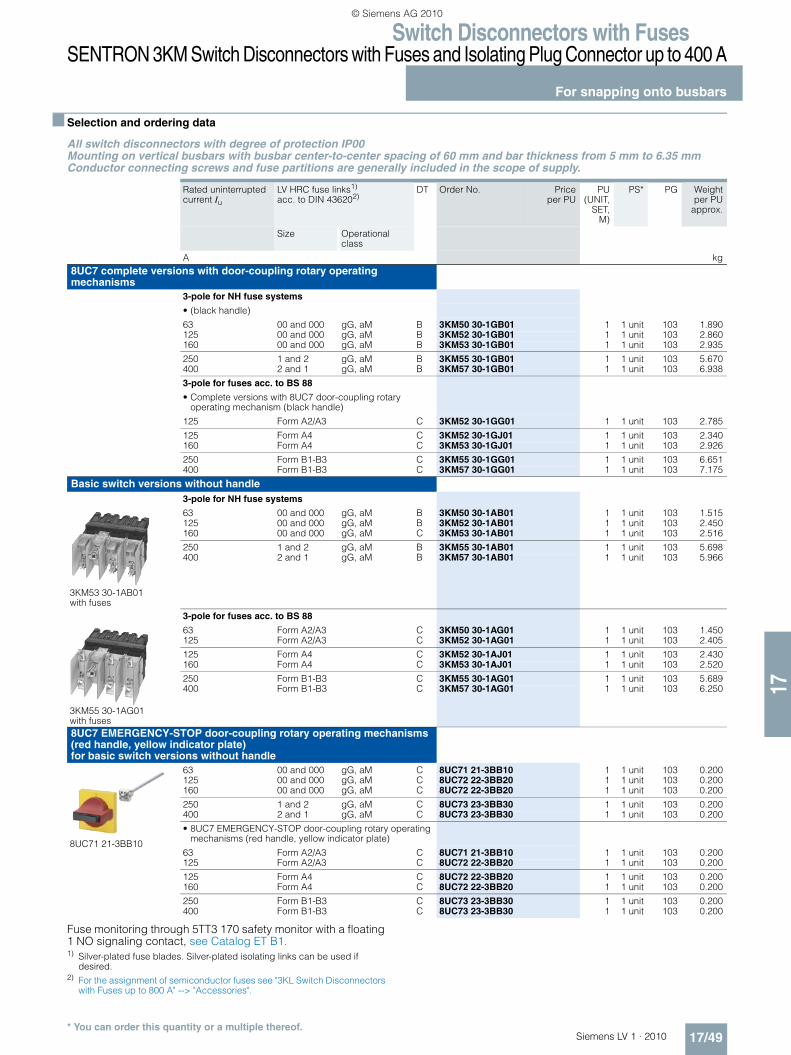
3KL52 30-1AB01
3-pole for NH fuse systems
63 00 and 000 gG, aM } 3KL50 30-1AB01 1 1 unit 103 1.055125 00 and 000 gG, aM } 3KL52 30-1AB01 1 1 unit 103 1.989160 00 and 000 gG, aM } 3KL53 30-1AB01 1 1 unit 103 2.200250 1 and 2 gG, aM } 3KL55 30-1AB01 1 1 unit 103 5.715
400 2 and 1 gG, aM } 3KL57 30-1AB01 1 1 unit 103 5.400630 3 and 2 gG, aM A 3KL61 30-1AB0 1 1 unit 113 17.6966303) 3 and 23) gG, aM3) A 3KL61 30-1AB02 1 1 unit 113 14.0008003) 3 and 23) gG, aM3) A 3KL62 30-1AB02 1 1 unit 113 15.200
3KL52 40-1AB01
4-pole for NH fuse systems
63 00 and 000 gG, aM B 3KL50 40-1AB01 1 1 unit 103 2.219125 00 and 000 gG, aM B 3KL52 40-1AB01 1 1 unit 103 2.195160 00 and 000 gG, aM B 3KL53 40-1AB01 1 1 unit 103 2.344
250 1 and 2 gG, aM B 3KL55 40-1AB01 1 1 unit 103 5.577400 2 and 1 gG, aM B 3KL57 40-1AB01 1 1 unit 103 5.670630 3 and 2 gG, aM A 3KL61 40-1AB00 1 1 unit 113 15.423
3KL52 30-1AJ01
3-pole for fuses acc. to BS 88
63 Form A2/A3 B 3KL50 30-1AG01 1 1 unit 103 0.993125 Form A2/A3 B 3KL52 30-1AG01 1 1 unit 103 1.939
125 Form A4 B 3KL52 30-1AJ01 1 1 unit 103 2.033160 Form A4 B 3KL53 30-1AJ01 1 1 unit 103 2.170
250 Form B1-B3 B 3KL55 30-1AG01 1 1 unit 103 5.145400 Form B1-B3 B 3KL57 30-1AG01 1 1 unit 103 5.666
630 Form C1-C3 A 3KL61 30-1AG00 1 1 unit 113 15.075800 Form C1-C3 C 3KL62 30-1AG00 1 1 unit 113 14.200
LV1_17.book Seite 40 Mittwoch, 16. Dezember 2009 4:15 16
© Siemens AG 2010

Switch Disconnectors with FusesSENTRON 3KL Switch Disconnectors with Fuses up to 800 A
Floor mounting
17/41Siemens LV 1 · 2010* You can order this quantity or a multiple thereof.
17
Fuse monitoring through 5TT3 170 safety monitor with a floating 1 NO signaling contact, see Catalog ET B1. Footnotes for pages 17/40 and 17/41: 1) Silver-plated fuse blades. Silver-plated isolating links can be used if
desired.2) For the assignment of semiconductor fuses see "Accessories".3) With SITOR 3NE fuse links cUus-approved.
Rated uninterrupted current Iu
LV HRC fuse links1) acc. to DIN 436202)
DT Order No. Priceper PU
PU(UNIT,
SET,M)
PS* PG Weightper PU
approx.
Size Operational class
A kg
3KL52 40-1AJ01 with fuses
4-pole for fuses acc. to BS 88
63 Form A2/A3 B 3KL50 40-1AG01 1 1 unit 103 2.145125 Form A2/A3 B 3KL52 40-1AG01 1 1 unit 103 2.161
125 Form A4 B 3KL52 40-1AJ01 1 1 unit 103 2.120160 Form A4 B 3KL53 40-1AJ01 1 1 unit 103 2.230
250 Form B1-B3 B 3KL55 40-1AG01 1 1 unit 103 5.666400 Form B1-B3 B 3KL57 40-1AG01 1 1 unit 103 6.441
630 Form C1-C3 C 3KL61 40-1AG00 1 1 unit 113 15.708
8UC7 EMERGENCY-STOP door-coupling rotary operating mechanisms (red handle, yellow indicator plate) for basic switch versions without handle
3-pole for NH fuse systems
8UC71 21-3BB10
63 00 and 000 gG, aM C 8UC71 21-3BB10 1 1 unit 103 0.200125 00 and 000 gG, aM C 8UC72 22-3BB20 1 1 unit 103 0.200160 00 and 000 gG, aM C 8UC72 22-3BB20 1 1 unit 103 0.200
250 1 and 2 gG, aM C 8UC73 23-3BB30 1 1 unit 103 0.200400 2 and 1 gG, aM C 8UC73 23-3BB30 1 1 unit 103 0.200
630 3 and 2 gG, aM C 8UC74 24-3BB44 1 1 unit 103 0.200+
} 8UC92 53 1 1 unit 103 0.115
800 3 and 2 gG, aM C 8UC74 24-3BB44 1 1 unit 103 0.200+
} 8UC92 53 1 1 unit 103 0.115
4-pole for NH fuse systems
63 00 and 000 gG, aM C 8UC72 22-3BB20 1 1 unit 103 0.200125 00 and 000 gG, aM C 8UC72 22-3BB20 1 1 unit 103 0.200160 00 and 000 gG, aM C 8UC72 22-3BB20 1 1 unit 103 0.200
250 1 and 2 gG, aM C 8UC73 23-3BB30 1 1 unit 103 0.200400 2 and 1 gG, aM C 8UC73 23-3BB30 1 1 unit 103 0.200
630 3 and 2 gG, aM C 8UC74 24-3BB44 1 1 unit 103 0.200+
} 8UC92 53 1 1 unit 103 0.115
3-pole for fuses acc. to BS 88
63 Form A2/A3 C 8UC71 21-3BB10 1 1 unit 103 0.200125 Form A2/A3 C 8UC72 22-3BB20 1 1 unit 103 0.200
125 Form A4 C 8UC72 22-3BB20 1 1 unit 103 0.200160 Form A4 C 8UC72 22-3BB20 1 1 unit 103 0.200
250 Form B1-B3 C 8UC73 23-3BB30 1 1 unit 103 0.200400 Form B1-B3 C 8UC73 23-3BB30 1 1 unit 103 0.200
630 Form C1-C3 C 8UC74 24-3BB44 1 1 unit 103 0.200+
} 8UC92 53 1 1 unit 103 0.115
800 Form C1-C3 C 8UC74 24-3BB44 1 1 unit 103 0.200+
} 8UC92 53 1 1 unit 103 0.115
4-pole for fuses acc. to BS 88
63 Form A2/A3 C 8UC72 22-3BB20 1 1 unit 103 0.200125 Form A2/A3 C 8UC72 22-3BB20 1 1 unit 103 0.200
125 Form A4 C 8UC72 22-3BB20 1 1 unit 103 0.200160 Form A4 C 8UC72 22-3BB20 1 1 unit 103 0.200
250 Form B1-B3 C 8UC73 23-3BB30 1 1 unit 103 0.200400 Form B1-B3 C 8UC73 23-3BB30 1 1 unit 103 0.200
630 Form C1-C3 C 8UC74 24-3BB44 1 1 unit 103 0.200+
} 8UC92 53 1 1 unit 103 0.115
LV1_17.book Seite 41 Mittwoch, 16. Dezember 2009 4:15 16
© Siemens AG 2010
Switch Disconnectors with FusesSENTRON 3KL Switch Disconnectors with Fuses up to 800 A
Front mounting
17/42 Siemens LV 1 · 2010* You can order this quantity or a multiple thereof.
17
■ Selection and ordering data
All switch disconnectors with degree of protection IP00Conductor connecting screws and fuse partitions are generally included in the scope of supply
Fuse monitoring through 5TT3 170 safety monitor with a floating 1 NO signaling contact, see Catalog ET B1. 1) Silver-plated fuse blades. Silver-plated isolating links can be used if
desired.2) For the assignment of semiconductor fuses see "Accessories".
Rated uninterrupted current Iu
LV HRC fuse links1) acc. to DIN 436202)
DT Order No. Priceper PU
PU(UNIT,
SET,M)
PS* PG Weightper PU
approx.
Size Operational class
A kgAssembly kits (IP40) comprising: lockable handle, cover for NH fuse systems (locked in ON state) and three terminal covers for infeed side for basic switch versions without handle
3-pole, assembly kits for mounting in control cabinet side panels
• Black handle
63 00 gG, aM B 3KX3 516-3AA 1 1 unit 103 0.626125 00 gG, aM B 3KX3 526-3AA 1 1 unit 103 0.820160 00 gG, aM B 3KX3 536-3AA 1 1 unit 103 0.880
250 1 and 2 gG, aM B 3KX3 556-3AA 1 1 unit 103 1.720400 2 and 1 gG, aM B 3KX3 556-3AA 1 1 unit 103 1.720
• EMERGENCY-STOP red handle
63 00 gG, aM B 3KX3 516-3BA 1 1 unit 103 0.625125 00 gG, aM B 3KX3 526-3BA 1 1 unit 103 0.846160 00 gG, aM B 3KX3 536-3BA 1 1 unit 103 0.883
250 1 and 2 gG, aM B 3KX3 556-3BA 1 1 unit 103 1.690400 2 and 1 gG, aM B 3KX3 556-3BA 1 1 unit 103 1.690
LV1_17.book Seite 42 Mittwoch, 16. Dezember 2009 4:15 16
© Siemens AG 2010
Switch Disconnectors with FusesSENTRON 3KL Switch Disconnectors with Fuses up to 800 A
Accessories
17/43Siemens LV 1 · 2010* You can order this quantity or a multiple thereof.
17
■ Selection and ordering data
1) For 3KX3 527-3AA: Not suitable for use with type A4 BS fuses.
Version DT Order No. Priceper PU
PU(UNIT,
SET,M)
PS* PG Weightper PU
approx.
kg
3KL50 30
3KX3 552-3DA01
Terminal cover
For 3-pole devices (1 set = 6 units) } 3KX3 552-3DA01 1 1 unit 103 0.077
3KX3 5.7-3AA
Fuse covers } 3KX3 517-3AA 1 1 unit 103 0.041(interlock only detachable in the OFF position)
Cover IP20 } 3KX3 507-0CA02 1 1 unit 103 0.400For 3-pole devices
Fuse partitions } 3KX3 507-0AA01 1 1 unit 103 0.044(1 set = 5 units)
3KX3 507-0BA01
Lyre-shaped fuse covers B 3KX3 507-0BA01 1 1 unit 103 0.033(1 set = 6 units)
Door-coupling rotary operating mechanisms IP65 Black handle, shaft 300 mm C 8UC71 11-1BB10 1 1 unit 103 0.200EMERGENCY-STOP (yellow/red), shaft 300 mm C 8UC71 21-3BB10 1 1 unit 103 0.200
Operating mechanisms for fixed mounting } 3KX3 516-1AA 1 1 unit 103 0.088Black handle, shaft 250 mm
Extension shaft 300 mm long B 8UC60 31 1 1 unit 103 0.068
Extension shaft 600 mm long B 8UC60 81 1 1 unit 103 0.136
Shaft connecting pieces B 8UC60 21 1 1 unit 103 0.031
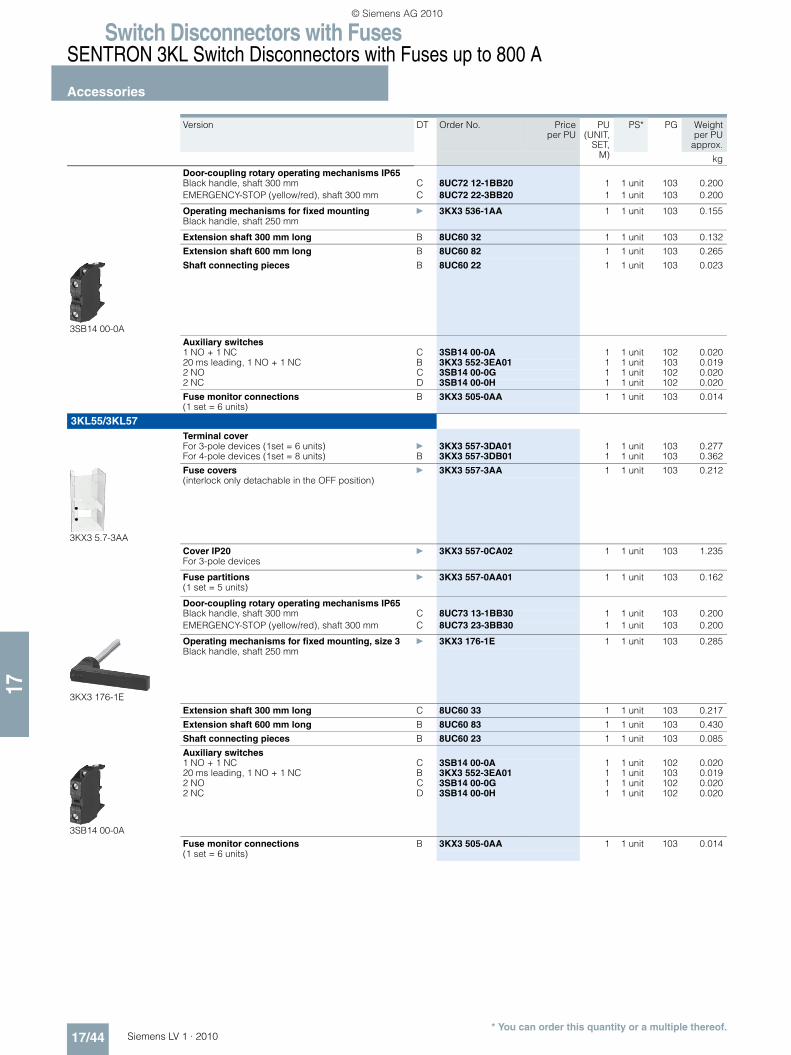
3SB14 00-0A
Auxiliary switches1 NO + 1 NC C 3SB14 00-0A 1 1 unit 102 0.0202 NO C 3SB14 00-0G 1 1 unit 102 0.0202 NC D 3SB14 00-0H 1 1 unit 102 0.020
Fuse monitor connections B 3KX3 505-0AA 1 1 unit 103 0.014(1 set = 6 units)
3KL50 40/3KL52/3KL53
3KX3 552-3DA01
Terminal coversFor 3-pole devices (1 set = 6 units)
• 3KL52 } 3KX3 552-3DA01 1 1 unit 103 0.077
• 3KL53 } 3KX3 553-3DA01 1 1 unit 103 0.147
For 4-pole devices (1 set = 8 units)
• 3KL50 40, 3KL52 B 3KX3 552-3DB01 1 1 unit 103 0.102
• 3KL53 B 3KX3 553-3DB01 1 1 unit 103 0.170
3KX3 5.7-3AA
Fuse covers1)
(interlock only detachable in the OFF position)} 3KX3 527-3AA 1 1 unit 103 0.071
Cover IP20 } 3KX3 527-0CA02 1 1 unit 103 0.765For 3KL52 3-pole devices
Cover IP20 } 3KX3 537-0CA02 1 1 unit 103 0.765For 3KL53 3-pole devices
Fuse partitions } 3KX3 507-0AA01 1 1 unit 103 0.044(1 set = 5 units)
3KX3 507-0BA01
Lyre-shaped fuse covers B 3KX3 507-0BA01 1 1 unit 103 0.033(1 set = 6 units)
LV1_17.book Seite 43 Mittwoch, 16. Dezember 2009 4:15 16
© Siemens AG 2010
Switch Disconnectors with FusesSENTRON 3KL Switch Disconnectors with Fuses up to 800 A
Accessories
17/44 Siemens LV 1 · 2010* You can order this quantity or a multiple thereof.
17
Version DT Order No. Priceper PU
PU(UNIT,
SET,M)
PS* PG Weightper PU
approx.
kg
Door-coupling rotary operating mechanisms IP65 Black handle, shaft 300 mm C 8UC72 12-1BB20 1 1 unit 103 0.200EMERGENCY-STOP (yellow/red), shaft 300 mm C 8UC72 22-3BB20 1 1 unit 103 0.200
Operating mechanisms for fixed mounting } 3KX3 536-1AA 1 1 unit 103 0.155Black handle, shaft 250 mm
Extension shaft 300 mm long B 8UC60 32 1 1 unit 103 0.132
Extension shaft 600 mm long B 8UC60 82 1 1 unit 103 0.265
3SB14 00-0A
Shaft connecting pieces B 8UC60 22 1 1 unit 103 0.023
Auxiliary switches1 NO + 1 NC C 3SB14 00-0A 1 1 unit 102 0.02020 ms leading, 1 NO + 1 NC B 3KX3 552-3EA01 1 1 unit 103 0.0192 NO C 3SB14 00-0G 1 1 unit 102 0.0202 NC D 3SB14 00-0H 1 1 unit 102 0.020
Fuse monitor connections B 3KX3 505-0AA 1 1 unit 103 0.014(1 set = 6 units)
3KL55/3KL57Terminal coverFor 3-pole devices (1set = 6 units) } 3KX3 557-3DA01 1 1 unit 103 0.277For 4-pole devices (1set = 8 units) B 3KX3 557-3DB01 1 1 unit 103 0.362
3KX3 5.7-3AA
Fuse covers } 3KX3 557-3AA 1 1 unit 103 0.212(interlock only detachable in the OFF position)
Cover IP20 } 3KX3 557-0CA02 1 1 unit 103 1.235For 3-pole devices
Fuse partitions } 3KX3 557-0AA01 1 1 unit 103 0.162(1 set = 5 units)
Door-coupling rotary operating mechanisms IP65 Black handle, shaft 300 mm C 8UC73 13-1BB30 1 1 unit 103 0.200EMERGENCY-STOP (yellow/red), shaft 300 mm C 8UC73 23-3BB30 1 1 unit 103 0.200
3KX3 176-1E
Operating mechanisms for fixed mounting, size 3 } 3KX3 176-1E 1 1 unit 103 0.285Black handle, shaft 250 mm
Extension shaft 300 mm long C 8UC60 33 1 1 unit 103 0.217
Extension shaft 600 mm long B 8UC60 83 1 1 unit 103 0.430
Shaft connecting pieces B 8UC60 23 1 1 unit 103 0.085
Auxiliary switches
3SB14 00-0A
1 NO + 1 NC C 3SB14 00-0A 1 1 unit 102 0.02020 ms leading, 1 NO + 1 NC B 3KX3 552-3EA01 1 1 unit 103 0.0192 NO C 3SB14 00-0G 1 1 unit 102 0.0202 NC D 3SB14 00-0H 1 1 unit 102 0.020
Fuse monitor connections B 3KX3 505-0AA 1 1 unit 103 0.014(1 set = 6 units)
LV1_17.book Seite 44 Mittwoch, 16. Dezember 2009 4:15 16
© Siemens AG 2010
Switch Disconnectors with FusesSENTRON 3KL Switch Disconnectors with Fuses up to 800 A
Accessories
17/45Siemens LV 1 · 2010* You can order this quantity or a multiple thereof.
17
1) Only for NH fuse systems.
SITOR fuses for 3KL and KM fuse switch disconnectors: Assignment table
1) Permissible load current in the switch disconnector.In the case of cyclic loads, the currents may have to be reduced again (precise values on request).
2) Values in blue in brackets apply to 3KM switch disconnectors.
Version DT Order No. Priceper PU
PU(UNIT,
SET,M)
PS* PG Weightper PU
approx.
kg
3KL61/3KL62Terminal cover
For 3-pole devices (1 set = 6 units) } 3KX3 561-3DA01 1 1 unit 103 0.263For 4-pole devices (1 set = 8 units) B 3KX3 561-3DB01 1 1 unit 103 0.365
Fuse coversCover plate A 3KX3 561-0AA00 1 1 unit 113 0.408Complete covers1) A 3KX3 561-1AA00 1 1 unit 113 0.408
8UC92 53
Door-coupling rotary operating mechanisms IP65Black handle, shaft 300 mm C 8UC74 14-1BB44 1 1 unit 103 0.200
+} 8UC92 53 1 1 unit 103 0.115
EMERGENCY-STOP (yellow/red), shaft 300 mm C 8UC74 24-3BB44 1 1 unit 103 0.200+
} 8UC92 53 1 1 unit 103 0.115
Operating mechanisms for fixed mounting, size 5 } 3KX3 616-1A 1 1 unit 103 0.490Black handle, shaft 250 mm
Extension shaft 300 mm long B 8UC60 34 1 1 unit 103 0.315
Extension shaft 600 mm long B 8UC60 84 1 1 unit 103 0.640
Shaft connecting pieces B 8UC60 24 1 1 unit 103 0.077
Auxiliary switches1 NO + 1 NC C 3KX3 612-1B 1 1 unit 113 0.2012 NO B 3SB34 00-0D 1 1 unit 102 0.0182 NC B 3SB34 00-0E 1 1 unit 102 0.018
for switch disconnectors SITOR fuses Order No. Priceper PU
PU(UNIT,
SET,M)
PS* PG Weightper PU
approx.Type 3KL(Type 3KM)
Permissible load current1)
Required conductor cross-section Cu
Size Opera-tional class
Rated current
Rated voltage
DT
A mm2 A V kg
SITOR 3NE1 fuses for 3KL5, 3KL6 and 3 KM53KL50 30 16 1.5 0001) gR/gS 16 690 } 3NE1 813-0 1 3 units 047 0.127(3KM50 30) 20 2.5 0001) gR/gS 20 690 } 3NE1 814-0 1 3 units 047 0.128
25 4 0001) gR/gS 25 690 } 3NE1 815-0 1 3 units 047 0.12735 6 0001) gR/gS 35 690 } 3NE1 803-0 1 3 units 047 0.12840 10 0001) gR/gS 40 690 } 3NE1 802-0 1 3 units 047 0.12750 10 0001) gR/gS 50 690 } 3NE1 817-0 1 3 units 047 0.12863 16 0001) gR/gS 63 690 } 3NE1 818-0 1 3 units 047 0.128
3KL52 30 80 25 0001) gR/gS 80 690 } 3NE1 820-0 1 3 units 047 0.129(3KM52 30) 100 35 00 gR/gS 100 690 } 3NE1 021-0 1 3 units 047 0.202
125 50 00 gR/gS 125 690 } 3NE1 022-0 1 3 units 047 0.202125 50 00 gR 125 690 A 3NE1 022-2 1 3 units 047 0.203
3KL55 30 160 70 1 gR/gS 160 690 } 3NE1 224-0 1 3 units 047 0.580(3KM55 30) 160 70 1 gR 160 690 A 3NE1 224-2 1 3 units 047 0.613
200 95 1 gR/gS 200 690 } 3NE1 225-0 1 3 units 047 0.582200 95 1 gR 200 690 A 3NE1 225-2 1 3 units 047 0.612250 120 1 gR/gS 250 690 } 3NE1 227-0 1 3 units 047 0.580245 120 1 gR 250 690 A 3NE1 227-2 1 3 units 047 0.626
3KL57 30 315 2 × 70 1 gR/gS 315 690 A 3NE1 230-0 1 3 units 047 0.581(3KM57 30) 280 2 × 70 1 gR 315 690 A 3NE1 230-2 1 3 units 047 0.615
3KL57 350 (330)2) 2 × 95 2 gR/gS 350 690 } 3NE1 331-0 1 3 units 047 0.7663KL61 30 350 (300)2) 2 × 95 2 gR 400 690 A 3NE1 331-2 1 3 units 047 0.754(3KM57 30) 400 (375)2) 2 × 95 2 gR/gS 400 690 } 3NE1 332-0 1 3 units 047 0.743
3KL61 30 450 (400)2) 2 × 120 2 gR/gS 450 690 A 3NE1 333-0 1 3 units 047 0.760(3KM57 30) 450 (325)2) 2 × 120 2 gR 450 690 A 3NE1 333-2 1 3 units 047 0.768
500 (400)2) 2 × 120 2 gR/gS 500 690 A 3NE1 334-0 1 3 units 047 0.766500 (350)2) 2 × 120 2 gR 500 690 A 3NE1 334-2 1 3 units 047 0.768
LV1_17.book Seite 45 Mittwoch, 16. Dezember 2009 4:15 16
© Siemens AG 2010

Switch Disconnectors with FusesSENTRON 3KL Switch Disconnectors with Fuses up to 800 A
Accessories
17/46 Siemens LV 1 · 2010* You can order this quantity or a multiple thereof.
17
For technical specifications and dimensional drawings of the SITOR fuses see Catalog ET B1.
For switch disconnectors SITOR fuses Order No. Priceper PU
PU(UNIT,
SET, M)
PS* PG Weightper PU
approx.Type 3KL(Type 3KM)
Permissible load current1)
Required conductor cross-section Cu
Size Opera-tional class
Rated current
Rated voltage
DT
A mm2 A V kg
3KL61 30 630 (710)3) 2 x (40 x 5) 3 gR/gS 710 690 A 3NE1 437-0 1 3 units 047 1.117(3KL62) 630 (710)3) 2 x (40 x 5) 3 gR 710 600 D 3NE1 437-1 1 3 units 047 1.120
630 (700)3) 2 x (40 x 5) 3 gR 710 690 B 3NE1 437-2 1 3 units 047 1.153630 (800)3) 2 x (50 x 5) 3 gR/gS 800 690
A3NE1 438-0 1 3 units 047 1.124
630 (800)3) 2 x (50 x 5) 3 gR 800 600 B 3NE1 438-1 1 3 units 047 1.113630 (760)3) 2 x (50 x 5) gR 800 690 A 3NE1 438-2 1 3 units 047 1.184
3KL61 30 630 (670)3) 2 x (40 x 5) 3 gR 670 690 A 3NE1 447-2 1 3 units 047 1.170(3KL62) 630 (790)3) 2 x (40 x 8) 3 gR 850 690 A 3NE1 448-2 1 3 units 047 1.207
SITOR fuses 3NE3 ... 3NE8, 3NC2 for 3KL5, 3KL6 and 3KM53KL50 25 4 00 gR 25 690 } 3NE8 015-1 1 3 units 047 0.205(3KM50) 33 6 00 gR 35 690 } 3NE8 003-1 1 3 units 047 0.204
45 10 00 gR 50 690 } 3NE8 017-1 1 3 units 047 0.20354 16 00 gR 63 690 } 3NE8 018-1 1 3 units 047 0.205
3KL52 68 25 00 aR 80 690 } 3NE8 020-1 1 3 units 047 0.203(3KM52) 89 35 00 aR 100 690 } 3NE8 021-1 1 3 units 047 0.205
106 50 00 aR 125 690 } 3NE8 022-1 1 3 units 047 0.213130 70 00 aR 160 690 } 3NE8 024-1 1 3 units 047 0.207
3KL552) 32 6 0 gR 32 1000 } 3NE4 101 1 3 units 047 0.278(3KM55)2) 40 10 0 gR 40 1000 } 3NE4 102 1 3 units 047 0.277
50 10 0 gR 50 1000 } 3NE4 117 1 3 units 047 0.27663 16 0 gR 63 1000 } 3NE4 118 1 3 units 047 0.279
80 25 0 aR 80 1000 } 3NE4 120 1 3 units 047 0.27695 35 0 aR 100 1000 } 3NE4 121 1 3 units 047 0.278
120 50 0 aR 125 1000 } 3NE4 122 1 3 units 047 0.279150 70 0 aR 160 1000 } 3NE4 124 1 3 units 047 0.279
90 35 1 aR 100 1000 A 3NE3 221 1 3 units 047 0.580110 50 1 aR 125 1000 A 3NE3 222 1 3 units 047 0.568140 70 1 aR 160 1000 } 3NE3 224 1 3 units 047 0.573175 95 1 aR 200 1000 } 3NE3 225 1 3 units 047 0.570210 120 1 aR 250 1000 } 3NE3 227 1 3 units 047 0.580
3KL57 240 185 1 aR 315 1000 } 3NE3 230-0B 1 3 units 047 0.585(3KM57) 265 240 1 aR 350 1000 A 3NE3 231 1 3 units 047 0.590
290 240 1 aR 400 1000 A 3NE3 232-0B 1 3 units 047 0.576320 2 × 150 1 aR 450 1000 } 3NE3 233 1 3 units 047 0.720
3KL61 340 (360)3) (290)4) 240 2 aR 400 1000 A 3NE3 332-0B 1 3 units 047 0.759(3KL62) 380 (400)3) (320)4) 2 × 150 2 aR 450 1000 A 3NE3 333 1 3 units 047 0.748(3KM57) 440 (470)3) (360)4) 2 × 150 2 aR 500 1000 } 3NE3 334-0B 1 3 units 047 0.753
500 (530)3) (400)4) 2 × 185 2 aR 560 1000 } 3NE3 335 1 3 units 047 0.756540 (580)3) (400)4) 2 × 185 2 aR 630 1000 } 3NE3 336 1 3 units 047 0.760
600 (640)3) (400)4) 2 × 200 2 aR 710 900 } 3NE3 337-8 1 3 units 047 0.762630 (720)3) (400)4) 2 × 200 2 aR 800 800 } 3NE3 338-8 1 3 units 047 0.764630 (800)3) (400)4) 2 × 200 2 aR 900 690 } 3NE3 340-8 1 3 units 047 0.753
200 (200)3) (175)4) 120 2 aR 250 800 } 3NE4 327-0B 1 3 units 047 0.753260 (260)3) (230)4) 240 2 aR 315 800 } 3NE4 330-0B 1 3 units 047 0.760370 (370)3) (340)4) 2 x (30 x 5) 2 aR 450 800 } 3NE4 333-0B 1 3 units 047 0.760425 (450)3) (380)4) 2 x (30 x 5) 2 aR 500 800 } 3NE4 334-0B 1 3 units 047 0.754600 (630)3) (400)4) 2 x (40 x 5) 2 aR 710 800 } 3NE4 337 1 3 units 047 0.771
3KL61 145 (150)3) 70 3 gR 150 500 B 3NC2 423-3C 1 3 units 047 0.940(3KL62) 180 (190)3) 95 3 gR 200 500 B 3NC2 425-3 1 3 units 047 1.057
225 (240)3) 120 3 gR 250 500 B 3NC2 427-3 1 3 units 047 1.066255 (270)3) 185 3 gR 300 500 B 3NC2 428-3 1 3 units 047 1.078330 (345)3) 240 3 gR 350 500 B 3NC2 431-3C 1 3 units 047 0.940400 (400)3) 240 3 gR 400 500 B 3NC2 432-3C 1 3 units 047 0.940
135 (140)3) 70 3 gR 150 660 B 3NC8 423-3 1 3 units 047 1.062180 (190)3) 95 3 gR 200 660 B 3NC8 425-3 1 3 units 047 1.063225 (240)3) 120 3 gR 250 660 B 3NC8 427-3 1 3 units 047 1.069300 (315)3) 240 3 gR 350 660 B 3NC8 431-3 1 3 units 047 1.072425 (450)3) 2 × 150 3 gR 500 660 B 3NC8 434-3 1 3 units 047 1.069
630 (800)3) 2 × (60 x 6) 3 aR 1000 600 C 3NC8 444-3 1 3 units 047 1.0851) Permissible load current in the switch disconnector.
In the case of cyclic loads, the currents may have to be reduced again (pre-cise values on request).
2) Due to the mechanical stress on the relatively long fuse blades, SITOR 3NE41 fuses should be switchable only occasionally and only at zero current.
3) Values in black in brackets apply to 3KL62 switch disconnectors.4) Values in blue in brackets apply to 3KM switch disconnectors.
LV1_17.book Seite 46 Mittwoch, 16. Dezember 2009 4:15 16
© Siemens AG 2010

Switch Disconnectors with FusesSENTRON 3KM Switch Disconnectors with Fuses and Isolating Plug Connector up to 400 A
General data
17/47Siemens LV 1 · 2010
17
■ Overview
All switch disconnectors feature double contact interruption and an isolating distance. As a result, the fuses are de-energized when the switch disconnectors are in the disconnected position.
The 3KM switch disconnectors with fuses also feature an isolat-ing plug connector. This facilitates mounting and contact estab-lishment in motor control centers (MCCs) in conjunction with ver-tical busbars. Generally, all 3K. 5 switch disconnectors can be
secured on the shaft with a padlock to prevent unauthorized re-closing.
Identical accessories for 3KA switch disconnectors and for 3KL and 3KM switch disconnectors with fuses simplify stock keep-ing.Please inquire about a special variant with reduced values that is particularly resistant to atmospheres high in sulfur, e. g. in the paper and cellulose processing industries.
■ Application3KM switch disconnectors with fuses protect against overload and short-circuits as main and EMERGENCY-STOP switches of switch boards, distribution boards, power supply and motor out-going feeders. In conjunction with Siemens SITOR semiconduc-tor fuses, they are also used in UPS systems, frequency converters and capacitor control systems.
All 3K switch disconnectors are climate-proof and meet the re-quirements of IEC 60947-1, IEC 60947-3 and VDE 0660 Part 107.
6
5
7
7
3
1
9
8
4
3
7
9
2
3KL or 3KM basic devicePlug-in contact strip for 3KM
Fuses, optionally BS-88 or LV HRC fuses
Coupling driver with extension shaft
Single-pole terminal cover from 63 A to 630 A, IP20 (vertical to operator side)
Terminal cover, IP20 (vertical to operator side)
Standard products from the Siemens 3SB1 range are used as auxiliary switches.
8UC9 knob for fixed mounting in standard version (black) or EMERGENCY-STOP version (red), or
All components from the switch to the actuator are provided with non-interchangeability features.
8UC7 door-coupling rotary operating mechanism in standard version (ti-grey) or EMERGENCY-STOP version (red/yellow)
Optional
NS
E0_
0155
7b
LV1_17.book Seite 47 Mittwoch, 16. Dezember 2009 4:15 16
© Siemens AG 2010

Switch Disconnectors with FusesSENTRON 3KM Switch Disconnectors with Fuses and Isolating Plug Connector up to 400 A
General data
17/48 Siemens LV 1 · 2010
17
■ More information
1) Configuring note: Max. permissible operating temperature for fuse blades 135 °C, for connections 100 °C.
2) 110 V (one conducting path).3) 220 V DC (L1 and L3 series-connected) or 110 V DC
(one conducting path) at DC-23A.4) At 440 V L/R = 4 ms, at 220 V L/R = 15 ms.5) At 440 V DC-22A, at 220 V DC-23A.6) 3ND1 switchgear protection fuse.
Standards IEC 60947-1, IEC 60947-3, VDE 0660 Part 107
Type 3KM50 3KM52 3KM53 3KM55 3KM57
Rated uninterrupted current Iu A 63 125 160 250 400For fuse links acc. to DIN 43620, (when SITOR semiconductor fuse links are used, a reduction of rated current is necessary, see Catalog Add-On ET B1 AO · 2009)
Size 00 and 000 00 and 000 00 and 000 1 and 2 1 and 2
Conventional free-air thermal current Ith1) A 63 125 160 250 400
Rated insulation voltage Ui V 690 1000 1000 1000 1000
Rated impulse voltage Uimp kV 6 8 8 8 8
Rated operational voltage Ue
AC 50 Hz/60 Hz V 690
DC V 440 (3 conducting paths series-connected)V 220 (2 conducting paths series-connected) 2)
Rated short-circuit making capacity with fuses kA 220 220 220 176 176(peak value, at 50 Hz/60 Hz 690 V AC)
Rated conditional short-circuit current with fuses kA 100 100 100 80 80(rms value, at 50 Hz/60 Hz 690 V AC)
Max. rated current In of the fuses A 80 160 160 400 400
Max. permissible power loss of the installed fuse
• NH W 6 9 11.5 32 45
• BS W 8 (A2/A3) 11.5 (A4) 11.5 32 45
Permissible let-through current of the fuses kA 8 17 17 303) 303)
Maximum permissible let-through I2t value kA2s 55 223 223 1000 1000
Switching capacity (infeed from the top or bottom)
At 400 V AC
• Breaking current Ic (at p.f. = 0.35, rms value) A 500 1000 1280 2000 3200
• Rated operational current Ie with AC-21A, AC-22A, AC-23A A 63 125 160 250 400
• Motor switching capacity AC-23A kW 30 65 80 132 200
At 500 V AC
• Breaking current Ic (at p.f. = 0.35, rms value) A 500 1000 1280 2000 3200
• Rated operational current Ie with AC-21A, AC-22A, AC-23A A 63 125 160 250 400
• Motor switching capacity AC-23A kW 40 90 110 185 280
At 690 V AC
• Breaking current Ic (at p.f. = 0.35, rms value) A 500 1000 1280 2000 3200
• Rated operational current Ie with AC-21A, AC-22A, AC-23A A 63 125 160 250 400
• Motor switching capacity AC-23A kW 50 110 150 220 375
At 440 V DC (3 conducting paths series-connected)4)
• Breaking current Ic (L/R = 15 ms) A 250 500 640 10004) 1600
• Rated operational current Ie at DC-23A A 63 125 160 2505) 400
Rated short-time current (1 s current), rms value kA 2.5 3.2 3.2 8 11
Permissible ambient temperature °C -25 ... +55 for operation6)
°C -50 ... +80 when stored
Mechanical endurance, operating cycles 15000 15000 15000 12000 12000
Degree of protection IP00/IP20 (from the operator side, with fuse and terminal covers)
Power loss of the switch disconnector at Ith W 8.5 22 36 33 86(plus power loss of the fuses)
Main conductor connections
Busbars, max. dimensions (w × t) mm 25 × 9 45 × 10 45 × 10 40 × 12 40 × 15
Cable lug, max. conductor cross-section (stranded) mm2 35 70 120 150 2 × 150 or 1 × 240
Busbars, max. dimensions (w × t) mm 25 × 9 45 × 10 45 × 10 40 × 12 40 × 15
Tightening torque Nm 6 ... 7.5 7 ... 10 18 ... 22 35 ... 45 35 ... 45
Terminal screws M6 M6 M8 M10 M10
Protective conductor connections
Flat bars mm -- -- -- 20 × 2.5 20 × 2.5
Cable lug, max. conductor cross-section (stranded) mm2 -- -- -- 70 120
LV1_17.book Seite 48 Mittwoch, 16. Dezember 2009 4:15 16
© Siemens AG 2010
Switch Disconnectors with FusesSENTRON 3KM Switch Disconnectors with Fuses and Isolating Plug Connector up to 400 A
For snapping onto busbars
17/49Siemens LV 1 · 2010* You can order this quantity or a multiple thereof.
17
■ Selection and ordering data
All switch disconnectors with degree of protection IP00Mounting on vertical busbars with busbar center-to-center spacing of 60 mm and bar thickness from 5 mm to 6.35 mmConductor connecting screws and fuse partitions are generally included in the scope of supply.
Fuse monitoring through 5TT3 170 safety monitor with a floating 1 NO signaling contact, see Catalog ET B1. 1) Silver-plated fuse blades. Silver-plated isolating links can be used if
desired.2) For the assignment of semiconductor fuses see "3KL Switch Disconnectors
with Fuses up to 800 A" --> "Accessories".
Rated uninterrupted current Iu
LV HRC fuse links1) acc. to DIN 436202)
DT Order No. Priceper PU
PU(UNIT,
SET,M)
PS* PG Weightper PU
approx.
Size Operational class
A kg8UC7 complete versions with door-coupling rotary operating mechanisms
3-pole for NH fuse systems
• (black handle)
63 00 and 000 gG, aM B 3KM50 30-1GB01 1 1 unit 103 1.890125 00 and 000 gG, aM B 3KM52 30-1GB01 1 1 unit 103 2.860160 00 and 000 gG, aM B 3KM53 30-1GB01 1 1 unit 103 2.935
250 1 and 2 gG, aM B 3KM55 30-1GB01 1 1 unit 103 5.670400 2 and 1 gG, aM B 3KM57 30-1GB01 1 1 unit 103 6.938
3-pole for fuses acc. to BS 88
• Complete versions with 8UC7 door-coupling rotary operating mechanism (black handle)
125 Form A2/A3 C 3KM52 30-1GG01 1 1 unit 103 2.785
125 Form A4 C 3KM52 30-1GJ01 1 1 unit 103 2.340160 Form A4 C 3KM53 30-1GJ01 1 1 unit 103 2.926
250 Form B1-B3 C 3KM55 30-1GG01 1 1 unit 103 6.651400 Form B1-B3 C 3KM57 30-1GG01 1 1 unit 103 7.175
Basic switch versions without handle3-pole for NH fuse systems
3KM53 30-1AB01 with fuses
63 00 and 000 gG, aM B 3KM50 30-1AB01 1 1 unit 103 1.515125 00 and 000 gG, aM B 3KM52 30-1AB01 1 1 unit 103 2.450160 00 and 000 gG, aM C 3KM53 30-1AB01 1 1 unit 103 2.516
250 1 and 2 gG, aM B 3KM55 30-1AB01 1 1 unit 103 5.698400 2 and 1 gG, aM B 3KM57 30-1AB01 1 1 unit 103 5.966
3-pole for fuses acc. to BS 88
3KM55 30-1AG01 with fuses
63 Form A2/A3 C 3KM50 30-1AG01 1 1 unit 103 1.450125 Form A2/A3 C 3KM52 30-1AG01 1 1 unit 103 2.405
125 Form A4 C 3KM52 30-1AJ01 1 1 unit 103 2.430160 Form A4 C 3KM53 30-1AJ01 1 1 unit 103 2.520
250 Form B1-B3 C 3KM55 30-1AG01 1 1 unit 103 5.689400 Form B1-B3 C 3KM57 30-1AG01 1 1 unit 103 6.250
8UC7 EMERGENCY-STOP door-coupling rotary operating mechanisms (red handle, yellow indicator plate) for basic switch versions without handle
8UC71 21-3BB10
63 00 and 000 gG, aM C 8UC71 21-3BB10 1 1 unit 103 0.200125 00 and 000 gG, aM C 8UC72 22-3BB20 1 1 unit 103 0.200160 00 and 000 gG, aM C 8UC72 22-3BB20 1 1 unit 103 0.200
250 1 and 2 gG, aM C 8UC73 23-3BB30 1 1 unit 103 0.200400 2 and 1 gG, aM C 8UC73 23-3BB30 1 1 unit 103 0.200
• 8UC7 EMERGENCY-STOP door-coupling rotary operating mechanisms (red handle, yellow indicator plate)
63 Form A2/A3 C 8UC71 21-3BB10 1 1 unit 103 0.200125 Form A2/A3 C 8UC72 22-3BB20 1 1 unit 103 0.200
125 Form A4 C 8UC72 22-3BB20 1 1 unit 103 0.200160 Form A4 C 8UC72 22-3BB20 1 1 unit 103 0.200
250 Form B1-B3 C 8UC73 23-3BB30 1 1 unit 103 0.200400 Form B1-B3 C 8UC73 23-3BB30 1 1 unit 103 0.200
LV1_17.book Seite 49 Mittwoch, 16. Dezember 2009 4:15 16
© Siemens AG 2010

Switch Disconnectors with FusesSENTRON 3KM Switch Disconnectors with Fuses and Isolating Plug Connector up to 400 A
Accessories
17/50 Siemens LV 1 · 2010* You can order this quantity or a multiple thereof.
17
■ Selection and ordering data
Version DT Order No. Priceper PU
PU(UNIT,
SET,M)
PS* PG Weightper PU
approx.
kg
3KM50Terminal coverFor 3-pole devices (1 set = 6 units) } 3KX3 552-3DA01 1 1 unit 103 0.077
3KX3 5.7-3AA
Fuse covers } 3KX3 517-3AA 1 1 unit 103 0.041(interlock only detachable in the OFF position)
Fuse partitions } 3KX3 507-0AA01 1 1 unit 103 0.044(1 set = 5 units)
3KX3 507-0BA01
Lyre-shaped fuse covers B 3KX3 507-0BA01 1 1 unit 103 0.033(1 set = 6 units)
Door-coupling rotary operating mechanisms IP65 Black handle, shaft 300 mm C 8UC71 11-1BB10 1 1 unit 103 0.200EMERGENCY-STOP (yellow/red), shaft 300 mm C 8UC71 21-3BB10 1 1 unit 103 0.200
Operating mechanisms for fixed mounting } 3KX3 516-1AA 1 1 unit 103 0.088Black handle, shaft 250 mm
Extension shaft 300 mm long B 8UC60 31 1 1 unit 103 0.068
Extension shaft 600 mm long B 8UC60 81 1 1 unit 103 0.136
Shaft connecting pieces B 8UC60 21 1 1 unit 103 0.031
3SB14 00-0A
Auxiliary switches1 NO + 1 NC C 3SB14 00-0A 1 1 unit 102 0.0202 NO C 3SB14 00-0G 1 1 unit 102 0.0202 NC D 3SB14 00-0H 1 1 unit 102 0.020
Fuse monitor connections B 3KX3 505-0AA 1 1 unit 103 0.014(1 set = 6 units)
3KM52/3KM53Terminal coverFor 3-pole devices (1 set = 6 units) 3KM52 } 3KX3 552-3DA01 1 1 unit 103 0.077
3KM53 } 3KX3 553-3DA01 1 1 unit 103 0.147For 4-pole devices (1 set = 8 units) 3KM52 B 3KX3 552-3DB01 1 1 unit 103 0.102
3KM53 B 3KX3 553-3DB01 1 1 unit 103 0.170
3KX3 5.7-3AA
Fuse covers1)} 3KX3 527-3AA 1 1 unit 103 0.071
(interlock only detachable in the OFF position)
Fuse partitions } 3KX3 507-0AA01 1 1 unit 103 0.044(1 set = 5 units)
3KX3 507-0BA01
Lyre-shaped fuse covers B 3KX3 507-0BA01 1 1 unit 103 0.033(1 set = 6 units)
Door-coupling rotary operating mechanisms IP65 Black handle, shaft 300 mm C 8UC72 12-1BB20 1 1 unit 103 0.200EMERGENCY-STOP (yellow/red), shaft 300 mm C 8UC72 22-3BB20 1 1 unit 103 0.200
Operating mechanisms for fixed mounting } 3KX3 536-1AA 1 1 unit 103 0.155Black handle, shaft 250 mm
1) For 3KX3 527-3AA: Not suitable for use with type A4 BS fuses.
LV1_17.book Seite 50 Mittwoch, 16. Dezember 2009 4:15 16
© Siemens AG 2010

Switch Disconnectors with FusesSENTRON 3KM Switch Disconnectors with Fuses and Isolating Plug Connector up to 400 A
Accessories
17/51Siemens LV 1 · 2010* You can order this quantity or a multiple thereof.
17
Version DT Order No. Priceper PU
PU(UNIT,
SET,M)
PS* PG Weightper PU
approx.
kg
3KM52/3KM53 (continued)Extension shaft 300 mm long B 8UC60 32 1 1 unit 103 0.132
Extension shaft 600 mm long B 8UC60 82 1 1 unit 103 0.265
Shaft connecting pieces B 8UC60 22 1 1 unit 103 0.023
3SB14 00-0A
Auxiliary switches1 NO + 1 NC C 3SB14 00-0A 1 1 unit 102 0.02020 ms leading, 1 NO + 1 NC B 3KX3 552-3EA01 1 1 unit 103 0.0192 NO C 3SB14 00-0G 1 1 unit 102 0.0202 NC D 3SB14 00-0H 1 1 unit 102 0.020
Fuse monitor connections B 3KX3 505-0AA 1 1 unit 103 0.014(1 set = 6 units)
3KM55/3KM57Terminal coverFor 3-pole devices (1 set = 6 units) } 3KX3 557-3DA01 1 1 unit 103 0.277For 4-pole devices (1 set = 8 units) B 3KX3 557-3DB01 1 1 unit 103 0.362
3KX3 5.7-3AA
Fuse covers } 3KX3 557-3AA 1 1 unit 103 0.212(interlock only detachable in the OFF position)
3KX3 557-0AA01
Fuse partitions } 3KX3 557-0AA01 1 1 unit 103 0.162(1 set = 5 units)
Door-coupling rotary operating mechanisms IP65Black handle, shaft 300 mm C 8UC73 13-1BB30 1 1 unit 103 0.200EMERGENCY-STOP (yellow/red), shaft 300 mm C 8UC73 23-3BB30 1 1 unit 103 0.200
3KX3 176-1E
Operating mechanisms for fixed mounting, size 3 } 3KX3 176-1E 1 1 unit 103 0.285Black handle, shaft 250 mm
Extension shaft 300 mm long C 8UC60 33 1 1 unit 103 0.217
Extension shaft 600 mm long B 8UC60 83 1 1 unit 103 0.430
Shaft connecting pieces B 8UC60 23 1 1 unit 103 0.085
Auxiliary switches
3SB14 00-0A
1 NO + 1 NC C 3SB14 00-0A 1 1 unit 102 0.02020 ms leading, 1 NO + 1 NC B 3KX3 552-3EA01 1 1 unit 103 0.0192 NO C 3SB14 00-0G 1 1 unit 102 0.0202 NC D 3SB14 00-0H 1 1 unit 102 0.020
Fuse monitor connections B 3KX3 505-0AA 1 1 unit 103 0.014(1 set = 6 units)
LV1_17.book Seite 51 Mittwoch, 16. Dezember 2009 4:15 16
© Siemens AG 2010

Switch Disconnectors with Fuses8UC Door-Coupling Rotary Operating Mechanisms
For 3K switch disconnectors
17/52 Siemens LV 1 · 2010
17
■ Overview
8UC7 rotary operating mechanism in STANDARD version (left) and EMERGENCY-STOP version (right)
With door-coupling rotary operating mechanisms it is also possi-ble to operate switch disconnectors from the outside with the control cabinet doors closed
The rotary operating mechanisms are available in "STANDARD" and "EMERGENCY-STOP" versions with the following differ-ences:• STANDARD version: Masking plates in light-gray with black in-
scription, handles in ti-grey.• EMERGENCY-STOP version: Masking plates in yellow with
black inscription, handles in red.
Available sizes
1) Operating mechanisms tested with triple torque (according to EN 60947-3). They are therefore also suitable for applications in this area.
2) Operation with two hands.
Degree of protection
Degree of protection when installed is IP65.
Standards
8UC7 door-coupling rotary operating mechanisms are in line with for example the following standards:
Design
The rotary operating mechanisms consist of a masking plate with handle, including seal and fixing screws for door installa-tion, an extension shaft (300 mm) and a coupling driver to be mounted onto the switch shaft.
Operating mechanisms for 3KA / 3KL / 3KM switch disconnec-tors do not have a shaft coupling since the extension shaft is fit-ted directly into the switch. Extension shafts with a length of 600 mm are also available.
Design, schematic representation
Switch position
In order to ensure compliance with locking and interlocking con-ditions, the controls and operating mechanisms must be in-stalled such that, with two-position switches the "0" position lies at 9 o'clock and the "I" position at 12 o'clock.
Positions for two-position switches with 90° operating angle
Rotary operating mechanisms
Size Rated torque1)
Shaft profile Masking plate
Nm mm x mm mm x mm
8UC71 1 4 6 x 6 75 x 75
8UC72 2 9 8 x 8 75 x 75
8UC73 3 25 10 x 10 or 12 x 12 100 x 100
8UC74 4 40/552) 12 x 12 100 x 100
IEC 60204-1, EN 60204-1 (VDE 0113 Part 1)
Electrical equipment of machines
IEC 60439-1, EN 60439-1 (VDE 0660 Part 500)
Low-voltage switchgear and controlgear assemblies
IEC 60947-3, EN 60947-3 (VDE 0660 Part 107)
Low-voltage switchgear and controlgear; load-break switches, disconnectors, switch disconnectors and fuse-com-bination units
Handle with masking frameSealDoorFixing screwsCoupling driverExtension shaftAdapterOperating shaft of switching deviceSwitching deviceTripped plate (can be glued on if required)
NS
E0_
0002
2a
1
23
45
6
7
8
9
10
123456789
10
90°
0°
NSE0_00352a
2
1
121 92
o'clock positiono'clock position
LV1_17.book Seite 52 Mittwoch, 16. Dezember 2009 4:15 16
© Siemens AG 2010

Switch Disconnectors with Fuses8UC Door-Coupling Rotary Operating Mechanisms
For 3K switch disconnectors
17/53Siemens LV 1 · 2010
17
■ Benefits
Can be locked
The retractable locking device integrated in the handles is suit-able for padlocks with shackle diameters of 4.5 mm to 8.5 mm (locks according to DIN 7465).
Up to three padlocks with a shackle diameter of 8.5 mm and up to five padlocks with a shackle diameter of 6 mm can be fitted simultaneously.
Non-interchangeability
In order to ensure that, when installing switches and door-cou-pling operating mechanisms, all components are assembled in the correct position with respect to one another, the components are provided with non-interchangeability features (rivel and lug).
Stops
Stops are used to prevent damage occuring as the result of ex-cessive torque. These stops are supplied loose with the rotary operating mechanisms and can be fitted as required. Stops are fitted at the factory to size 1 and 2 rotary operating mechanisms with a 90° operating angle (exception: 3RV motor starter protec-tors).
Tolerance compensation
8UC7 rotary operating mechanisms are capable of taking up a radial eccentricity of max. 3 mm between the actuating shaft of the switching device and the door-coupling rotary operating mechanism. Supporting the extension shaft is recommended with greater tolerances.
Permissible radial eccentricity and axial tolerance compensation in mm
Pull-out strengthThe pull-out strength of interlocked operating mechanisms, e. g. pulling off the shaft or destruction of the operating mechanism, amounts to 800 N when the pulling force acts directly onto the operating mechanism in di-rection of shaft.
■ Application
8UC7 door-coupling rotary operating mechanisms can be used in electrical controls, distribution boards and switchboards in cases where switches have to be mounted behind covers, end plates and doors that must be opened and where they are to be operated manually from outside.
Interlocking conditions
The basic versions of the rotary operating mechanisms comply with the following interlocking conditions:• Operating mechanism and switch in "0" (OFF) position: The
control cabinet door can be opened. With padlocks fitted, the control cabinet door remains locked however.
• Operating mechanism and switch in "I" (ON) position: The con-trol cabinet door cannot be opened in this position. However, the interlock can be overridden and the control cabinet door opened by trained personnel for performing checks. No padlocks can be fitted in "I" position.
Other interlocking conditions:• If no door interlock is required, the user can remove the door
interlocking plate of the rotary operating mechanism. • It is easy for the user to fit padlocks to the rotary operating
mechanisms in the "I" position as well. In this case the door cannot be opened, the operating mechanism cannot be actu-ated and the door interlock cannot be overridden.
Operating conditions and ambient conditions
The temperature range for operation of the rotary operating mechanisms is between -25 °C and +60 °C.
Thanks to the use of glass fiber-reinforced molded plastic for handles and masking plates as well as metal components with surface protection, the rotary operating mechanisms are suit-able for rough conditions, high air humidity and aggressive at-mospheres.
NSE0_00945aCoupling drivers
a b Shaft length
With tolerance compensation
+3 ±5 x
Without tolerance compensation
+1.5 ±2.5 x+23.5
LV1_17.book Seite 53 Mittwoch, 16. Dezember 2009 4:15 16
© Siemens AG 2010

Switch Disconnectors with Fuses8UC Door-Coupling Rotary Operating Mechanisms
For 3K switch disconnectors
17/54 Siemens LV 1 · 2010
17
■ Selection and ordering data
Door-coupling rotary operating mechanisms, fully lockable with padlocks, with door interlock supplied with seal and fixing screws
Switching device Rated current Cross-section of the actuating shaft
Torque Rotary operating mechanisms
Illustrated: Handle, masking plate
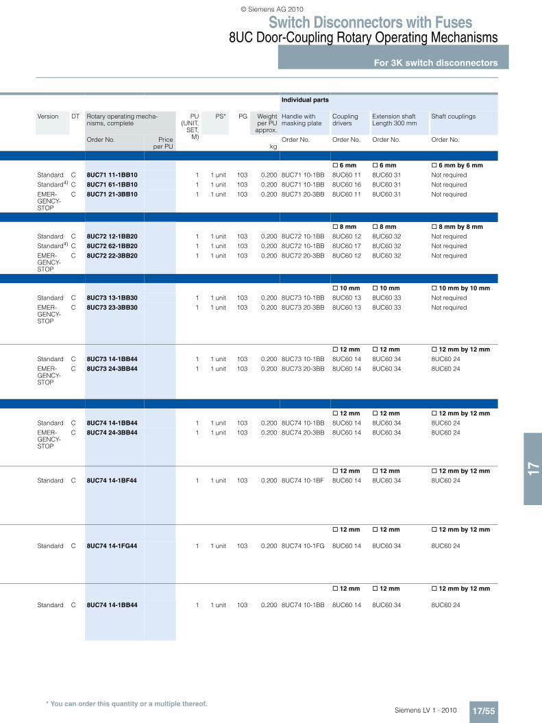
Type A mm Nm Size8UC71
For switch disconnectors with or without fuses
3KL501), 3KM501) 63 6 x 6 3 1
3KA501) 63 6 x 6 3
3KA511) 80 6 x 6 3
8UC72 For switch disconnectors with or without fuses
3KL52, 3KM52 125 8 x 8 7.5 2
3KL53, 3KM53 160 8 x 8 7.5
3KA52 125 8 x 8 7.5
3KA53 160 8 x 8 7.5
8UC73
For switch disconnectors with or without fuses
3KL55, 3KM55 250 10 x 10 16 3
3KL57, 3KM57 400 10 x 10 16
3KA55 250 10 x 10 16
3KA57 400 10 x 10 163KA58 630 10 x 10 16
For switch disconnectors without fuses
3KE42 250 12 x 12 15 3
3KE43 400 12 x 12 15
3KE44 630 12 x 12 24
3KE45 1000 12 x 12 24
8UC74
For switch disconnectors with fuses
3KL612) 630 12 x 12 30 4
3KL622) 800 12 x 12 30
For switch disconnectors as changeover switches with break-before-make feature
3KE42 (2 units) 250 12 x 12 20 4
3KE43 (2 units) 400 12 x 12 20
3KE44 (2 units) 630 12 x 12 30
3KE45 (2 units) 1000 12 x 12 30
For switch disconnectors as changeover switches without break-before-make feature
3KE42 (2 units) 250 12 x 12 40 4
3KE43 (2 units) 400 12 x 12 40
3KE44 (2 units) 630 12 x 12 55
3KE45 (2 units) 1000 12 x 12 55
For switch disconnectors as changeover switches without break-before-make feature
3KE42 (2 units) 250 12 x 12 40 4
3KE43 (2 units) 400 12 x 12 40
3KE44 (2 units) 630 12 x 12 55
3KE45 (2 units) 1000 12 x 12 55
��
��
��
��
��
�
��
��
��
�
��
��
��
��
��
���
���
��
��
��
��
���
���
��
��
��
�
���
��
NSE
0_01
892
100
200
NSE0_01891
200
100
��
��
��
�
���
��
1) Valid only for 3-pole switching devices. For 4-pole switching devices, an operating mechanism with 8 x 8 mm actuating shaft must be used, see lower level for 3KA52, 3KL52 or 3KM52.
2) Additionally required for 3KL61: 1 shaft coupling, Order No. 8UC92 53, see "Individual Parts", table on page 17/56.
3) The door interlocking plate must be removed.4) With shortened 8UC60 16/8UC60 17 coupling driver and reduced toler-
ance compensation, see "Dimensional Drawings".
LV1_17.book Seite 54 Mittwoch, 16. Dezember 2009 4:15 16
© Siemens AG 2010
Switch Disconnectors with Fuses8UC Door-Coupling Rotary Operating Mechanisms
For 3K switch disconnectors
17/55Siemens LV 1 · 2010* You can order this quantity or a multiple thereof.
17
Individual parts
Version DT Rotary operating mecha-nisms, complete
PU(UNIT,
SET,M)
PS* PG Weightper PU
approx.
Handle with masking plate
Coupling drivers
Extension shaft Length 300 mm
Shaft couplings
Order No. Priceper PU kg
Order No. Order No. Order No. Order No.
@ 6 mm @ 6 mm @ 6 mm by 6 mm
Standard C 8UC71 11-1BB10 1 1 unit 103 0.200 8UC71 10-1BB 8UC60 11 8UC60 31 Not required
Standard4) C 8UC71 61-1BB10 1 1 unit 103 0.200 8UC71 10-1BB 8UC60 16 8UC60 31 Not required
EMER-GENCY-STOP
C 8UC71 21-3BB10 1 1 unit 103 0.200 8UC71 20-3BB 8UC60 11 8UC60 31 Not required
@ 8 mm @ 8 mm @ 8 mm by 8 mm
Standard C 8UC72 12-1BB20 1 1 unit 103 0.200 8UC72 10-1BB 8UC60 12 8UC60 32 Not required
Standard4) C 8UC72 62-1BB20 1 1 unit 103 0.200 8UC72 10-1BB 8UC60 17 8UC60 32 Not required
EMER-GENCY-STOP
C 8UC72 22-3BB20 1 1 unit 103 0.200 8UC72 20-3BB 8UC60 12 8UC60 32 Not required
@ 10 mm @ 10 mm @ 10 mm by 10 mm
Standard C 8UC73 13-1BB30 1 1 unit 103 0.200 8UC73 10-1BB 8UC60 13 8UC60 33 Not required
EMER-GENCY-STOP
C 8UC73 23-3BB30 1 1 unit 103 0.200 8UC73 20-3BB 8UC60 13 8UC60 33 Not required
@ 12 mm @ 12 mm @ 12 mm by 12 mm
Standard C 8UC73 14-1BB44 1 1 unit 103 0.200 8UC73 10-1BB 8UC60 14 8UC60 34 8UC60 24
EMER-GENCY-STOP
C 8UC73 24-3BB44 1 1 unit 103 0.200 8UC73 20-3BB 8UC60 14 8UC60 34 8UC60 24
@ 12 mm @ 12 mm @ 12 mm by 12 mm
Standard C 8UC74 14-1BB44 1 1 unit 103 0.200 8UC74 10-1BB 8UC60 14 8UC60 34 8UC60 24
EMER-GENCY-STOP
C 8UC74 24-3BB44 1 1 unit 103 0.200 8UC74 20-3BB 8UC60 14 8UC60 34 8UC60 24
@ 12 mm @ 12 mm @ 12 mm by 12 mm
Standard C 8UC74 14-1BF44 1 1 unit 103 0.200 8UC74 10-1BF 8UC60 14 8UC60 34 8UC60 24
@ 12 mm @ 12 mm @ 12 mm by 12 mm
Standard C 8UC74 14-1FG44 1 1 unit 103 0.200 8UC74 10-1FG 8UC60 14 8UC60 34 8UC60 24
@ 12 mm @ 12 mm @ 12 mm by 12 mm
Standard C 8UC74 14-1BB44 1 1 unit 103 0.200 8UC74 10-1BB 8UC60 14 8UC60 34 8UC60 24
LV1_17.book Seite 55 Mittwoch, 16. Dezember 2009 4:15 16
© Siemens AG 2010

Switch Disconnectors with Fuses8UC Door-Coupling Rotary Operating Mechanisms
Individual parts
17/56 Siemens LV 1 · 2010* You can order this quantity or a multiple thereof.
17
■ Selection and ordering data
1) Non-interchangeability features.2) Shortened coupling driver with reduced tolerance compensation.
3) For switch disconnectors as changeover switches in various versions, see table on page 17/54
4) Standard: Ti-grey handle, light-gray masking plate; EMERGENCY-STOP: Red handle, yellow masking plate.
Switching device
Rotary operating mecha-nisms
Size Cross-section of the actuating shaft
Version4) DT Individual parts for 8UC7 door-coupling rotary operating mechanisms
PU(UNIT,
SET, M)
PS* PG Weightper PU
approx.
Order No. Priceper PU
Type Type mm × mm kgHandles with masking plate (including flat gasket and fixing screws)
8UC71 10-1BB
3KL50,3KM50,3KA50,3KA51
8UC71 1 6 × 6 Standard C 8UC71 10-1BB 1 1 unit 103 0.200
E-STOP C 8UC71 20-3BB 1 1 unit 103 0.200
8UC72 10-6BD
3KL52, 3KM52, 3KL53, 3KM53, 3KA52, 3KA53
8UC72 2 8 × 8 Standard C 8UC72 10-1BB 1 1 unit 103 0.200
E-STOP C 8UC72 20-3BB 1 1 unit 103 0.200
8UC73 10-1BB
3KL55, 3KM55, 3KL57, 3KM57, 3KA55, 3KA57, 3KE42, 3KE43, 3KE44, 3KE45
8UC73 3 10 × 10or12 x 12
Standard C 8UC73 10-1BB 1 1 unit 103 0.200
E-STOP C 8UC73 20-3BB 1 1 unit 103 0.200
8UC74 10-1BB
3KL61, 3KL62 8UC74 4 12 × 12 Standard C 8UC74 10-1BB 1 1 unit 103 0.200
E-STOP C 8UC74 20-3BB 1 1 unit 103 0.200
3KE42, 3KE43, 3KE44, 3KE45
8UC743) 4 12 × 12 Standard C 8UC74 10-1BF 1 1 unit 103 0.200
Standard C 8UC74 10-1FG 1 1 unit 103 0.200
Standard C 8UC74 10-1BB 1 1 unit 103 0.200
Rotary operating mecha-nisms
Cross-section of the actuating shaft
DT Individual parts for 8UC6 door-coupling rotary operating mechanisms
PU(UNIT,
SET, M)
PS* PG Weightper PU
approx.
Order No. Priceper PUType mm × mm kg
Coupling drivers, extension shafts, shaft couplings and reducers
8UC60 11
Coupling drivers for 3K
8UC71 6 × 6 B 8UC60 11 1 1 unit 103 0.0788UC712) 6 × 6 A 8UC60 16 1 1 unit 103 0.0708UC72 8 × 8 B 8UC60 12 1 1 unit 103 0.0758UC722) 8 × 8 A 8UC60 17 1 1 unit 103 0.0438UC73 10 × 10 B 8UC60 13 1 1 unit 103 0.2518UC73/74 12 × 12 B 8UC60 14 1 1 unit 103 0.253
8UC60 31 ... 34
Extension shafts 300 mm long
8UC71 6 × 6 B 8UC60 31 1 1 unit 103 0.0688UC72 8 × 8 B 8UC60 32 1 1 unit 103 0.1328UC73 10 × 10 C 8UC60 33 1 1 unit 103 0.2178UC73/74 12 × 12 B 8UC60 34 1 1 unit 103 0.315
8UC60 81 ... 84
Extension shafts 600 mm long
8UC71 6 × 6 B 8UC60 81 1 1 unit 103 0.136
8UC72 8 × 8 B 8UC60 82 1 1 unit 103 0.2658UC73 10 × 10 B 8UC60 83 1 1 unit 103 0.4308UC73/74 12 × 12 B 8UC60 84 1 1 unit 103 0.640
8UC60 21 to 8UC6024
Shaft couplings
8UC71 6 × 6 B 8UC60 21 1 1 unit 103 0.0318UC72 8 × 8 B 8UC60 22 1 1 unit 103 0.0238UC73 10 × 10 B 8UC60 23 1 1 unit 103 0.0858UC73/74 12 × 12 B 8UC60 24 1 1 unit 103 0.0778UC74 (3KL61) 12 × 12 } 8UC92 53 1 1 unit 103 0.115
8UC70 58 8UC70 50
Reducers
8UC71 8 × 8 to 6 × 6 C 8UC70 58 1 1 unit 103 0.2008UC72 12 × 12 to 8 × 8 C 8UC70 50 1 1 unit 103 0.200
nse0_00372 Rivet
NSE0_00373
Groove
NSE0_00373
Groove
nse0_00374
RivetLug
nsg0_00245nsg0_00244
LV1_17.book Seite 56 Mittwoch, 16. Dezember 2009 4:15 16
© Siemens AG 2010

Switch Disconnectors with Fuses8UC Door-Coupling Rotary Operating Mechanisms
Operating mechanisms for fixed mounting
17/57Siemens LV 1 · 2010* You can order this quantity or a multiple thereof.
17
■ Selection and ordering data
1) Operating mechanisms were tested with triple torque (DIN VDE 0660 Part 107). They are therefore qualified for use in all controls, especially for disconnectors.
2) Red handle available on request.3) Also required: 3KX2 210-0H coupling socket.
Switch-ing device
Cross-section of the actuating shaft
Torque of the operat-ing mecha-nism1)
Oper-ating mecha-nism
Color of handle
DT Operating mechanisms for fixed mounting
PU(UNIT,
SET,M)
PS* PG Weightper PU
approx.
Order No. Priceper PU
Type mm × mm Nm Size kg
8UC93 54
3KA50, 3KA51, 3KL50, 3KM50
6 × 6 4 1 Black 2) B 8UC93 54 1 1 unit 103 0.031
8UC93 60
7.5 2 Black 2) B 8UC93 60 1 1 unit 103 0.047
3KA52 3KA53, 3KL52, 3KM52, 3KL53, 3KM53
8 × 8 7.5 2 Black B 8UC93 62 1 1 unit 103 0.041
Red B 8UC93 63 1 1 unit 103 0.044
8UC93 65
3KL55, 3KM55, 3KL57, 3KM57
10 × 10 16 3 Black B 8UC93 65 1 1 unit 103 0.138
3KA55, 3KA57, 3KA58
Red B 8UC93 66 1 1 unit 103 0.160
3KE42, 3KE43
12 × 12 16 3 Black 3) B 8UC93 70 1 1 unit 103 0.128
Red 3) B 8UC93 71 1 1 unit 103 0.146
8UC93 74
3KE44, 3KE45
12 × 12 30 4 Black 3) B 8UC93 74 1 1 unit 103 0.145
Red 3) B 8UC93 75 1 1 unit 103 0.165
8UC93 81
3KL61 12 × 12 55 5 Black B 8UC93 81 1 1 unit 103 0.264
Red B 8UC93 82 1 1 unit 103 0.273
LV1_17.book Seite 57 Mittwoch, 16. Dezember 2009 4:15 16
© Siemens AG 2010

Switch Disconnectors with FusesSENTRON 3NJ6 In-Line Switch Disconnectors with Fuses up to 630 A3NJ62 switch disconnectors with fusesGeneral data
17/58 Siemens LV 1 · 2010
17
■ Overview
3NJ62 Switch Disconnectors with Fuses
All key product features at a glance• In-line• Type-tested according to IEC EN 60947-3• Voltage levels up to 690 V AC• 160 A to 630 A for LV HRC and BS 88 fuse links,
according to IEC 60269-1/EN 60269-1• 3-/4-pole versions available• 185 mm phase center distance of plug-in contacts• Manually operated or with motorized operating mechanism• Electronic fuse monitoring (EFM)• Developed for switchgears in plug-in design• Horizontal or vertical mounting position• Front panel locked in ON position• Degree of protection IP41
Overview of components and accessory parts
1
2
3
4
5
6
7
8
9
10
11
12
13
14
15
16
17
18
3NJ62 switch disconnector basic deviceher in size 00, open, without front panel
Guide rails
Blanking cover
Connection module
Busbar cover
Contact extension
Current transformer
Current transformer busbar
Terminals
Stud terminal
Terminal cover
Auxiliary switch
Holder for measuring instruments
Multi-function plug
Moving-iron measuring instrument
Bi-metal measuring instrument
LV HRC fuse links
BS fuse links
NS
E0_
0191
7a
LV1_17.book Seite 58 Mittwoch, 16. Dezember 2009 4:15 16
© Siemens AG 2010

Switch Disconnectors with FusesSENTRON 3NJ6 In-Line Switch Disconnectors with Fuses up to 630 A
3NJ62 switch disconnectors with fusesGeneral data
17/59Siemens LV 1 · 2010
17
■ Benefits
Key advantages for switchgear manufacturers due to the fol-lowing:• Compact, modular design• Simple and efficient mounting due to incoming plug-in contact• High packing density in the field• Cable connection with cable clamps or cable lugs• Can be mounted in different control cabinet depths• Comprehensive range of accessories
The advantages for users are:• Conversion, retrofitting and replacement without switching off
the switchgear• Dead-state fuse replacement• Maintenance free• High personal safety• Operating handle can be locked in OFF position• Clear and unambiguous switch position indicator
■ Application
The plug-in 3NJ6 switch disconnectors with fuses are installed in low-voltage distribution boards where a minimum amount of space is available for a maximum number of cable ducts to the power distribution. They can be easily fitted in all common con-trol cabinets (minimum depth: 400 mm).
The plug-in 3NJ62 switch disconnectors with fuses are available for rated uninterrupted currents from 160 A to 630 A.
LV HRC fuse links according to IEC 60269-1/EN 60269-1 (sizes NH 00 to NH 3) or BS fuse links according to BS 88 provide over-load and short-circuit protection up to 690 V AC.
The switch disconnectors can be retrofitted at any time with aux-iliary switches, an ammeter (48 mm x 48 mm) and current trans-formers, with no extra space required. For installation in control cabinets of > 400 mm depth, the mounting depth of the discon-nectors can be increased by 200 mm using a contact extension. Further installation accessories, such as guide rails and blank-ing covers, complete the product range.
LV1_17.book Seite 59 Mittwoch, 16. Dezember 2009 4:15 16
© Siemens AG 2010
Switch Disconnectors with FusesSENTRON 3NJ6 In-Line Switch Disconnectors with Fuses up to 630 A3NJ62 switch disconnectors with fusesGeneral data
17/60 Siemens LV 1 · 2010
17
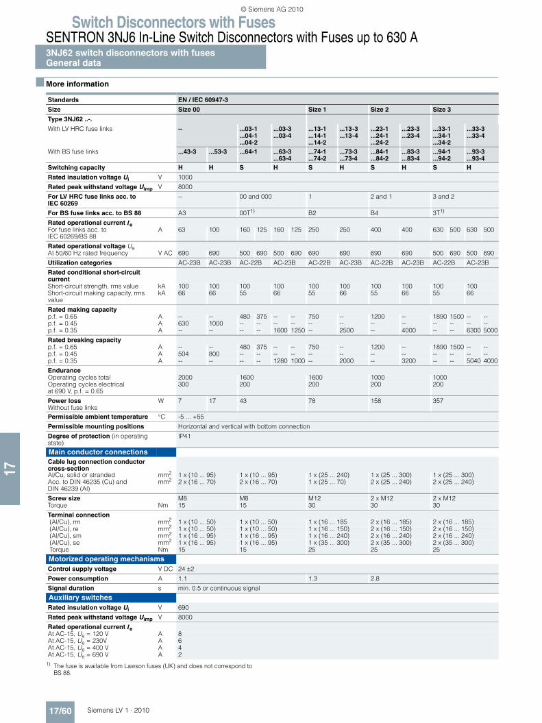
■ More information
1) The fuse is available from Lawson fuses (UK) and does not correspond to BS 88.
Standards EN / IEC 60947-3
Size Size 00 Size 1 Size 2 Size 3
Type 3NJ62 ..-.
With LV HRC fuse links -- ...03-1...04-1...04-2
...03-3
...03-4...13-1...14-1...14-2
...13-3
...13-4...23-1...24-1...24-2
...23-3
...23-4...33-1...34-1...34-2
...33-3
...33-4
With BS fuse links ...43-3 ...53-3 ...64-1 ...63-3...63-4
...74-1
...74-2...73-3...73-4
...84-1
...84-2...83-3...83-4
...94-1
...94-2...93-3...93-4
Switching capacity H H S H S H S H S H
Rated insulation voltage Ui V 1000
Rated peak withstand voltage Uimp V 8000
For LV HRC fuse links acc. to IEC 60269
-- 00 and 000 1 2 and 1 3 and 2
For BS fuse links acc. to BS 88 A3 00T1) B2 B4 3T1)
Rated operational current Ie For fuse links acc. to IEC 60269/BS 88
A 63 100 160 125 160 125 250 250 400 400 630 500 630 500
Rated operational voltage Ue At 50/60 Hz rated frequency V AC 690 690 500 690 500 690 690 690 690 690 500 690 500 690
Utilization categories AC-23B AC-23B AC-22B AC-23B AC-22B AC-23B AC-22B AC-23B AC-22B AC-23B
Rated conditional short-circuit current Short-circuit strength, rms value kA 100 100 100 100 100 100 100 100 100 100Short-circuit making capacity, rms value
kA 66 66 55 66 55 66 55 66 55 66
Rated making capacityp.f. = 0.65 A -- -- 480 375 -- -- 750 -- 1200 -- 1890 1500 -- --p.f. = 0.45 A 630 1000 -- -- -- -- -- -- -- -- -- -- -- --p.f. = 0.35 A -- -- -- -- 1600 1250 -- 2500 -- 4000 -- -- 6300 5000
Rated breaking capacityp.f. = 0.65 A -- -- 480 375 -- -- 750 -- 1200 -- 1890 1500 -- --p.f. = 0.45 A 504 800 -- -- -- -- -- -- -- -- -- -- -- --p.f. = 0.35 A -- -- -- -- 1280 1000 -- 2000 -- 3200 -- -- 5040 4000
EnduranceOperating cycles total 2000 1600 1600 1000 1000Operating cycles electrical at 690 V, p.f. = 0.65
300 200 200 200 200
Power lossWithout fuse links
W 7 17 43 78 158 357
Permissible ambient temperature °C -5 ... +55
Permissible mounting positions Horizontal and vertical with bottom connection
Degree of protection (in operating state)
IP41
Main conductor connections Cable lug connection conductor cross-sectionAl/Cu, solid or stranded mm2 1 x (10 ... 95) 1 x (10 ... 95) 1 x (25 ... 240) 1 x (25 ... 300) 1 x (25 ... 300)Acc. to DIN 46235 (Cu) and DIN 46239 (Al)
mm2 2 x (16 ... 70) 2 x (16 ... 70) 1 x (25 ... 70) 2 x (25 ... 240) 2 x (25 ... 240)
Screw size M8 M8 M12 2 x M12 2 x M12Torque Nm 15 15 30 30 30
Terminal connection (Al/Cu), rm mm2 1 x (10 ... 50) 1 x (10 ... 50) 1 x (16 ... 185 2 x (16 ... 185) 2 x (16 ... 185) (Al/Cu), re mm2 1 x (10 ... 50) 1 x (10 ... 50) 1 x (16 ... 150) 2 x (16 ... 150) 2 x (16 ... 150) (Al/Cu), sm mm2 1 x (16 ... 95) 1 x (16 ... 95) 1 x (16 ... 240) 2 x (16 ... 240) 2 x (16 ... 240) (Al/Cu), se mm2 1 x (16 ... 95) 1 x (16 ... 95) 1 x (35 ... 300) 2 x (35 ... 300) 2 x (35 ... 300) Torque Nm 15 15 25 25 25
Motorized operating mechanismsControl supply voltage V DC 24 ±2
Power consumption A 1.1 1.3 2.8
Signal duration s min. 0.5 or continuous signal
Auxiliary switchesRated insulation voltage Ui V 690
Rated peak withstand voltage Uimp V 8000
Rated operational current Ie At AC-15, Ue = 120 V A 8At AC-15, Ue = 230V A 6At AC-15, Ue = 400 V A 4At AC-15, Ue = 690 V A 2
LV1_17.book Seite 60 Mittwoch, 16. Dezember 2009 4:15 16
© Siemens AG 2010

Switch Disconnectors with FusesSENTRON 3NJ6 In-Line Switch Disconnectors with Fuses up to 630 A
3NJ62 switch disconnectors with fusesfor LV HRC fuse links
17/61Siemens LV 1 · 2010* You can order this quantity or a multiple thereof.
17
■ Selection and ordering data
Rated current In Size DT Order No. Priceper PU
PU(UNIT,
SET, M)
PS* PG Weightper PU
approx.
A kg
3-pole, standard switching capacity S
Manually operated160 00/000 A 3NJ62 03-1AA0@-@@@@ 1 1 unit 143 3.630250 1 A 3NJ62 13-1AA0@-@@@@ 1 1 unit 143 6.750400 2/1 A 3NJ62 23-1AA0@-@@@@ 1 1 unit 143 15.000630 3/2 A 3NJ62 33-1AA0@-@@@@ 1 1 unit 143 15.360
3-pole, high switching capacity H
Manually operated160 00/000 A 3NJ62 03-3AA0@-@@@@ 1 1 unit 143 3.630250 1 A 3NJ62 13-3AA0@-@@@@ 1 1 unit 143 6.750400 2/1 A 3NJ62 23-3AA0@-@@@@ 1 1 unit 143 15.000630 3/2 A 3NJ62 33-3AA0@-@@@@ 1 1 unit 143 15.360
Manually operated, EFM 160 00/000 A 3NJ62 03-3AV0@-@@@@ 1 1 unit 143 3.630250 1 A 3NJ62 13-3AV0@-@@@@ 1 1 unit 143 6.750400 2/1 A 3NJ62 23-3AV0@-@@@@ 1 1 unit 143 15.000630 3/2 A 3NJ62 33-3AV0@-@@@@ 1 1 unit 143 15.360
Motorized operating mechanisms160 00/000 C 3NJ62 03-4AA0@-@@@@ 1 1 unit 143 3.630250 1 C 3NJ62 13-4AA0@-@@@@ 1 1 unit 143 6.750400 2/1 C 3NJ62 23-4AA0@-@@@@ 1 1 unit 143 15.000630 3/2 C 3NJ62 33-4AA0@-@@@@ 1 1 unit 143 15.360
Motorized operating mechanism, EFM160 00/000 C 3NJ62 03-4AV0@-@@@@ 1 1 unit 143 3.630250 1 C 3NJ62 13-4AV0@-@@@@ 1 1 unit 143 6.750400 2/1 C 3NJ62 23-4AV0@-@@@@ 1 1 unit 143 15.000630 3/2 C 3NJ62 33-4AV0@-@@@@ 1 1 unit 143 15.360
4-pole, standard switching capacity S
Manually operated160 00/000 A 3NJ62 04-1AA0@-@@@@ 1 1 unit 143 6.160250 1 A 3NJ62 14-1AA0@-@@@@ 1 1 unit 143 10.380400 2/1 A 3NJ62 24-1AA0@-@@@@ 1 1 unit 143 18.900630 3/2 A 3NJ62 34-1AA0@-@@@@ 1 1 unit 143 20.000
Manually operated, EFM 160 00/000 C 3NJ62 04-1AV0@-@@@@ 1 1 unit 143 6.160250 1 C 3NJ62 14-1AV0@-@@@@ 1 1 unit 143 10.380400 2/1 C 3NJ62 24-1AV0@-@@@@ 1 1 unit 143 18.900630 3/2 C 3NJ62 34-1AV0@-@@@@ 1 1 unit 143 20.000
Motorized operating mechanisms160 00/000 C 3NJ62 04-2AA0@-@@@@ 1 1 unit 143 6.160250 1 C 3NJ62 14-2AA0@-@@@@ 1 1 unit 143 10.380400 2/1 C 3NJ62 24-2AA0@-@@@@ 1 1 unit 143 18.900630 3/2 C 3NJ62 34-2AA0@-@@@@ 1 1 unit 143 20.000
Motorized operating mechanism, EFM160 00/000 C 3NJ62 04-2AV0@-@@@@ 1 1 unit 143 6.160250 1 C 3NJ62 14-2AV0@-@@@@ 1 1 unit 143 10.380400 2/1 C 3NJ62 24-2AV0@-@@@@ 1 1 unit 143 18.900630 3/2 C 3NJ62 34-2AV0@-@@@@ 1 1 unit 143 20.000
Order No. supplement Add. price
Standard Order No. supplement (more Order No. supplements on page 17/63 onwards)
Without auxiliary switches, ammeters, current transformers } None0 0 A A 0
LV1_17.book Seite 61 Mittwoch, 16. Dezember 2009 4:15 16
© Siemens AG 2010

Switch Disconnectors with FusesSENTRON 3NJ6 In-Line Switch Disconnectors with Fuses up to 630 A3NJ62 switch disconnectors with fusesfor BS fuse links
17/62 Siemens LV 1 · 2010* You can order this quantity or a multiple thereof.
17
■ Selection and ordering data
1) The fuse is available from Lawson fuses (UK) and does not correspond to BS 88.
Rated current In Size DT Order No. Priceper PU
PU(UNIT,
SET, M)
PS* PG Weightper PU
approx.
A kg
3-pole, high switching capacity H
Manually operated 63 A3 C 3NJ62 43-3AA0@-@@@@ 1 1 unit 143 3.630
100 A3 C 3NJ62 53-3AA0@-@@@@ 1 1 unit 143 3.630160 00T1) C 3NJ62 63-3AA0@-@@@@ 1 1 unit 143 3.630250 B2 C 3NJ62 73-3AA0@-@@@@ 1 1 unit 143 6.750400 B4 C 3NJ62 83-3AA0@-@@@@ 1 1 unit 143 15.000630 3T1) C 3NJ62 93-3AA0@-@@@@ 1 1 unit 143 15.360
Manually operated, EFM 160 00T1) C 3NJ62 63-3AV0@-@@@@ 1 1 unit 143 3.630250 B2 C 3NJ62 73-3AV0@-@@@@ 1 1 unit 143 6.750400 B4 C 3NJ62 83-3AV0@-@@@@ 1 1 unit 143 15.000630 3T1) C 3NJ62 93-3AV0@-@@@@ 1 1 unit 143 15.360
Motorized operating mechanisms160 00T1) C 3NJ62 63-4AA0@-@@@@ 1 1 unit 143 3.630250 B2 C 3NJ62 73-4AA0@-@@@@ 1 1 unit 143 6.750400 B4 C 3NJ62 83-4AA0@-@@@@ 1 1 unit 143 15.000630 3T1) C 3NJ62 93-4AA0@-@@@@ 1 1 unit 143 15.360
4-pole, standard switching capacity S
Manually operated160 00T1) C 3NJ62 64-1AA0@-@@@@ 1 1 unit 143 6.160250 B2 C 3NJ62 74-1AA0@-@@@@ 1 1 unit 143 10.380400 B4 C 3NJ62 84-1AA0@-@@@@ 1 1 unit 143 18.900630 3T1) C 3NJ62 94-1AA0@-@@@@ 1 1 unit 143 20.000
Manually operated, EFM 160 00T1) C 3NJ62 64-1AV0@-@@@@ 1 1 unit 143 6.160250 B2 C 3NJ62 74-1AV0@-@@@@ 1 1 unit 143 10.380400 B4 C 3NJ62 84-1AV0@-@@@@ 1 1 unit 143 18.900630 3T1) C 3NJ62 94-1AV0@-@@@@ 1 1 unit 143 20.000
Motorized operating mechanisms160 00T1) C 3NJ62 64-2AA0@-@@@@ 1 1 unit 143 6.160250 B2 C 3NJ62 74-2AA0@-@@@@ 1 1 unit 143 10.380400 B4 C 3NJ62 84-2AA0@-@@@@ 1 1 unit 143 18.900630 3T1) C 3NJ62 94-2AA0@-@@@@ 1 1 unit 143 20.000
Order No. supplement Add. price
Standard Order No. supplement (more Order No. supplements on page 17/63 onwards)
Without auxiliary switches, ammeters, current transformers } None0 0 A A 0
LV1_17.book Seite 62 Mittwoch, 16. Dezember 2009 4:15 16
© Siemens AG 2010
Switch Disconnectors with FusesSENTRON 3NJ6 In-Line Switch Disconnectors with Fuses up to 630 A
3NJ62 switch disconnectors with fusesfor LV HRC and BS fuse links
17/63Siemens LV 1 · 2010
17
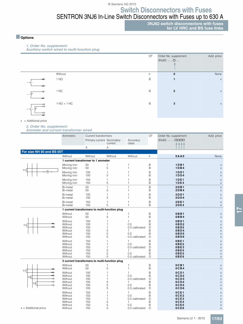
■ Options
x = Additional price
1. Order No. supplement: Auxiliary switch wired to multi-function plug
DT Order No. supplement
3NJ62 ..-....@-....
Add. price
Without } 0 None
1 NO B 1 x
1 NC B 2 x
1 NO + 1 NC B 3 x
2. Order No. supplement:Ammeter and current transformer wired
Ammeters Current transformers DT Order No. supplement
3NJ62 ..-.....-@@@@
Add. price
Primary current Secondary current
Accuracy class
A A
For size NH 00 and BS 00TWithout Without Without Without } 0 A A 0 None
1 current transformer to 1 ammeter
Moving iron 50 1 1 B 1 D B 1 xMoving iron 50 5 1 B 1 D B 4 x
Moving iron 100 1 1 B 1 D D 1 xMoving iron 100 5 1 B 1 D D 4 x
Moving iron 150 1 1 B 1 D E 1 xMoving iron 150 5 1 B 1 D E 4 x
Bi-metal 50 1 1 B 2 D B 1 xBi-metal 50 5 1 B 2 D B 4 x
Bi-metal 100 1 1 B 2 D D 1 xBi-metal 100 5 1 B 2 D D 4 x
Bi-metal 150 1 1 B 2 D E 1 xBi-metal 150 5 1 B 2 D E 4 x
1 current transformers to multi-function plug
Without 50 1 1 B 0 B B 1 xWithout 50 5 1 B 0 B B 4 x
Without 100 1 1 B 0 B D 1 xWithout 100 1 0.5 B 0 B D 2 xWithout 100 1 0.5 calibrated D 0 B D3 xWithout 100 5 1 B 0 B D 4 xWithout 100 5 0.5 B 0 B D 5 xWithout 100 5 0.5 calibrated D 0 B D 6 x
Without 150 1 1 B 0 B E 1 xWithout 150 1 0.5 B 0 B E 2 xWithout 150 1 0.5 calibrated D 0 B E 3 xWithout 150 5 1 B 0 B E 4 xWithout 150 5 0.5 B 0 B E 5 xWithout 150 5 0.5 calibrated D 0 B E 6 x
3 current transformers to multi-function plug
Without 50 1 1 B 0 C B 1 xWithout 50 5 1 B 0 C B 4 x
Without 100 1 1 B 0 C D 1 xWithout 100 1 0.5 B 0 C D 2 xWithout 100 1 0.5 calibrated D 0 C D 3 xWithout 100 5 1 B 0 C D 4 xWithout 100 5 0.5 B 0 C D 5 xWithout 100 5 0.5 calibrated D 0 C D 6 x
Without 150 1 1 B 0 C E 1 xWithout 150 1 0.5 B 0 C E 2 xWithout 150 1 0.5 calibrated D 0 C E 3 xWithout 150 5 1 B 0 C E 4 xWithout 150 5 0.5 B 0 C E 5 xWithout 150 5 0.5 calibrated D 0 C E 6 x
T1 A
T1
T1
T2
T3
x = Additional price
LV1_17.book Seite 63 Dienstag, 12. Januar 2010 3:40 15
© Siemens AG 2010
Switch Disconnectors with FusesSENTRON 3NJ6 In-Line Switch Disconnectors with Fuses up to 630 A3NJ62 switch disconnectors with fusesfor LV HRC and BS fuse links
17/64 Siemens LV 1 · 2010
17
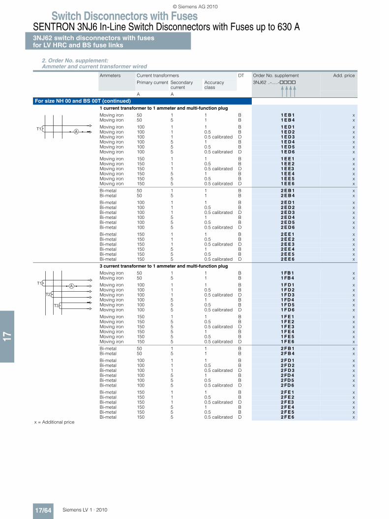
For size NH 00 and BS 00T (continued)1 current transformer to 1 ammeter and multi-function plug
Moving iron 50 1 1 B 1 E B 1 xMoving iron 50 5 1 B 1 E B 4 x
Moving iron 100 1 1 B 1 E D 1 xMoving iron 100 1 0.5 B 1 E D 2 xMoving iron 100 1 0.5 calibrated D 1 E D 3 xMoving iron 100 5 1 B 1 E D 4 xMoving iron 100 5 0.5 B 1 E D 5 xMoving iron 100 5 0.5 calibrated D 1 E D 6 x
Moving iron 150 1 1 B 1 E E 1 xMoving iron 150 1 0.5 B 1 E E 2 xMoving iron 150 1 0.5 calibrated D 1 E E3 xMoving iron 150 5 1 B 1 E E 4 xMoving iron 150 5 0.5 B 1 E E 5 xMoving iron 150 5 0.5 calibrated D 1 E E 6 x
Bi-metal 50 1 1 B 2 E B 1 xBi-metal 50 5 1 B 2 E B 4 x
Bi-metal 100 1 1 B 2 E D 1 xBi-metal 100 1 0.5 B 2 E D 2 xBi-metal 100 1 0.5 calibrated D 2 E D 3 xBi-metal 100 5 1 B 2 E D 4 xBi-metal 100 5 0.5 B 2 E D 5 xBi-metal 100 5 0.5 calibrated D 2 E D 6 x
Bi-metal 150 1 1 B 2 E E 1 xBi-metal 150 1 0.5 B 2 E E 2 xBi-metal 150 1 0.5 calibrated D 2 E E 3 xBi-metal 150 5 1 B 2 E E 4 xBi-metal 150 5 0.5 B 2 E E 5 xBi-metal 150 5 0.5 calibrated D 2 E E 6 x
3 current transformer to 1 ammeter and multi-function plug
Moving iron 50 1 1 B 1 FB 1 xMoving iron 50 5 1 B 1 FB 4 x
Moving iron 100 1 1 B 1 F D 1 xMoving iron 100 1 0.5 B 1 F D 2 xMoving iron 100 1 0.5 calibrated D 1 F D 3 xMoving iron 100 5 1 B 1 FD 4 xMoving iron 100 5 0.5 B 1 F D 5 xMoving iron 100 5 0.5 calibrated D 1 F D 6 x
Moving iron 150 1 1 B 1 F E 1 xMoving iron 150 5 0.5 B 1 F E 2 xMoving iron 150 5 0.5 calibrated D 1 F E 3 xMoving iron 150 5 1 B 1 F E 4 xMoving iron 150 5 0.5 B 1 F E 5 xMoving iron 150 5 0.5 calibrated D 1 F E 6 x
Bi-metal 50 1 1 B 2 F B 1 xBi-metal 50 5 1 B 2 F B 4 x
Bi-metal 100 1 1 B 2 F D 1 xBi-metal 100 1 0.5 B 2 F D 2 xBi-metal 100 1 0.5 calibrated D 2 F D 3 xBi-metal 100 5 1 B 2 FD 4 xBi-metal 100 5 0.5 B 2 FD 5 xBi-metal 100 5 0.5 calibrated D 2 FD 6 x
Bi-metal 150 1 1 B 2 F E 1 xBi-metal 150 1 0.5 B 2 F E 2 xBi-metal 150 1 0.5 calibrated D 2 F E3 xBi-metal 150 5 1 B 2 F E 4 xBi-metal 150 5 0.5 B 2 F E 5 xBi-metal 150 5 0.5 calibrated D 2 F E 6 x
x = Additional price
2. Order No. supplement:Ammeter and current transformer wired
Ammeters Current transformers DT Order No. supplement
3NJ62 ..-.....-@@@@
Add. price
Primary current Secondary current
Accuracy class
A A
AT1
T1
T2
T3
A
LV1_17.book Seite 64 Dienstag, 12. Januar 2010 3:40 15
© Siemens AG 2010

Switch Disconnectors with FusesSENTRON 3NJ6 In-Line Switch Disconnectors with Fuses up to 630 A
3NJ62 switch disconnectors with fusesfor LV HRC and BS fuse links
17/65Siemens LV 1 · 2010
17
Ammeters Current transformers DT Order No. supplement
3NJ62 ..-.....-@@@@
Add. price
Primary current Secondary current
Accuracy class
A A
For size NH 1 and BS B2Without Without Without Without } 0 A A 0 None
1 current transformer to 1 ammeter
Moving iron 50 1 1 B 1 D B 1 xMoving iron 50 5 1 B 1 D B 4 x
Moving iron 100 1 1 B 1 D D 1 xMoving iron 100 5 1 B 1 D D 4 x
Moving iron 150 1 1 B 1 D E 1 xMoving iron 150 5 1 B 1 D E 4 x
Moving iron 200 1 1 B 1 D F1 xMoving iron 200 5 1 B 1 D F 4 x
Moving iron 250 1 1 B 1 D G1 xMoving iron 250 5 1 B 1 D G 4 x
Bi-metal 50 1 1 B 2 D B 1 xBi-metal 50 5 1 B 2 D B 4 x
Bi-metal 100 1 1 B 2 D D 1 xBi-metal 100 5 1 B 2 D D 4 x
Bi-metal 150 1 1 B 2 D E 1 xBi-metal 150 5 1 B 2 D E 4 x
Bi-metal 200 1 1 B 2 D F1 xBi-metal 200 5 1 B 2 D F4 x
Bi-metal 250 1 1 B 2 D G 1 xBi-metal 250 5 1 B 2 D G 4 x
1 current transformers to multi-function plug
Without 50 1 1 B 0 B B 1 xWithout 50 5 1 B 0 B B 4 x
Without 100 1 1 B 0 B D 1 xWithout 100 1 0.5 B 0 B D 2 xWithout 100 5 1 B 0 B D 4 xWithout 100 5 0.5 B 0 B D 5 x
Without 150 1 1 B 0 B E 1 xWithout 150 1 0.5 B 0 B E 2 xWithout 150 5 1 B 0 B E 4 xWithout 150 5 0.5 B 0 B E 5 x
Without 200 1 1 B 0 B F 1 xWithout 200 1 0.5 B 0 B F 2 xWithout 200 5 1 B 0 B F 4 xWithout 200 5 0.5 B 0 B F 5 x
Without 250 1 1 B 0 B G 1 xWithout 250 1 0.5 B 0 B G 2 xWithout 250 5 1 B 0 B G 4 xWithout 250 5 0.5 B 0 B G 5 x
3 current transformers to multi-function plug
Without 50 1 1 B 0 C B 1 xWithout 50 5 1 B 0 C B 4 x
Without 100 1 1 B 0C D 1 xWithout 100 1 0.5 B 0C D 2 xWithout 100 5 1 B 0C D 4 xWithout 100 5 0.5 B 0C D 5 x
Without 150 1 1 B 0C E 1 xWithout 150 1 0.5 B 0C E 2 xWithout 150 5 1 B 0C E 4 xWithout 150 5 0.5 B 0C E 5 x
Without 200 1 1 B 0C F 1 xWithout 200 1 0.5 B 0C F 2 xWithout 200 5 1 B 0 C F4 xWithout 200 5 0.5 B 0 C F 5 x
Without 250 1 1 B 0 C G 1 xWithout 250 1 0.5 B 0 C G 2 xWithout 250 5 1 B 0 C G 4 xWithout 250 5 0.5 B 0 C G 5 x
x = Additional price
T1 A
T1
T1
T2
T3
LV1_17.book Seite 65 Dienstag, 12. Januar 2010 3:40 15
© Siemens AG 2010

Switch Disconnectors with FusesSENTRON 3NJ6 In-Line Switch Disconnectors with Fuses up to 630 A3NJ62 switch disconnectors with fusesfor LV HRC and BS fuse links
17/66 Siemens LV 1 · 2010
17
For size NH 1 and BS B2 (continued)1 current transformer to 1 ammeter and multi-function plugMoving iron 50 1 1 B 1 E B 1 xMoving iron 50 5 1 B 1 E B 4 x
Moving iron 100 1 1 B 1 E D 1 xMoving iron 100 1 0.5 B 1 E D 2 xMoving iron 100 5 1 B 1 E D 4 xMoving iron 100 5 0.5 B 1 E D 5 xMoving iron 150 1 1 B 1 E E 1 xMoving iron 150 1 0.5 B 1 E E 2 xMoving iron 150 5 1 B 1 E E 4 xMoving iron 150 5 0.5 B 1 E E 5 xMoving iron 200 1 1 B 1 E F 1 xMoving iron 200 1 0.5 B 1 E F 2 xMoving iron 200 5 1 B 1 E F 4 xMoving iron 200 5 0.5 B 1 E F 5 xMoving iron 250 1 1 B 1 E G 1 xMoving iron 250 1 0.5 B 1 E G 2 xMoving iron 250 5 1 B 1 E G 4 xMoving iron 250 5 0.5 B 1 E G 5 x
Bi-metal 50 1 1 B 2 E B 1 xBi-metal 50 5 1 B 2 E B 4 x
Bi-metal 100 1 1 B 2 E D 1 xBi-metal 100 1 0.5 B 2 E D 2 xBi-metal 100 5 1 B 2 E D 4 xBi-metal 100 5 0.5 B 2 E D 5 x
Bi-metal 150 1 1 B 2 E E 1 xBi-metal 150 1 0.5 B 2 E E 2 xBi-metal 150 5 1 B 2 E E 4 xBi-metal 150 5 0.5 B 2 E E 5 x
Bi-metal 200 1 1 B 2 E F 1 xBi-metal 200 1 0.5 B 2 E F 2 xBi-metal 200 5 1 B 2 E F 4 xBi-metal 200 5 0.5 B 2 E F 5 x
Bi-metal 250 1 1 B 2 EG 1 xBi-metal 250 1 0.5 B 2 EG 2 xBi-metal 250 5 1 B 2 EG 4 xBi-metal 250 5 0.5 B 2 EG 5 x
3 current transformer to 1 ammeter and multi-function plug
Moving iron 50 1 1 B 1 F B 1 xMoving iron 50 5 1 B 1 F B 4 x
Moving iron 100 1 1 B 1 F D 1 xMoving iron 100 1 0.5 B 1 F D 2 xMoving iron 100 5 1 B 1 F D 4 xMoving iron 100 5 0.5 B 1 F D 5 x
Moving iron 150 1 1 B 1 F E 1 xMoving iron 150 1 0.5 B 1 F E 2 xMoving iron 150 5 1 B 1 F E 4 xMoving iron 150 5 0.5 B 1 F E 5 x
Moving iron 200 1 1 B 1 F F 1 xMoving iron 200 1 0.5 B 1 F F 2 xMoving iron 200 5 1 B 1 F F 4 xMoving iron 200 5 0.5 B 1 F F 5 x
Moving iron 250 1 1 B 1 F G 1 xMoving iron 250 1 0.5 B 1 F G 2 xMoving iron 250 5 1 B 1 F G 4 xMoving iron 250 5 0.5 B 1 F G 5 x
Bi-metal 50 1 1 B 2 F B 1 xBi-metal 50 5 1 B 2 F B 4 x
Bi-metal 100 1 1 B 2 F D 1 xBi-metal 100 1 0.5 B 2 F D 2 xBi-metal 100 5 1 B 2 F D 4 xBi-metal 100 5 0.5 B 2 F D 5 x
Bi-metal 150 1 1 B 2 F E 1 xBi-metal 150 1 0.5 B 2 F E2 xBi-metal 150 5 1 B 2 F E 4 xBi-metal 150 5 0.5 B 2 F E 5 x
Bi-metal 200 1 1 B 2 F F 1 xBi-metal 200 1 0.5 B 2 F F 2 xBi-metal 200 5 1 B 2 F F 4 xBi-metal 200 5 0.5 B 2 F F 5 x
Bi-metal 250 1 1 B 2 FG 1 xBi-metal 250 1 0.5 B 2 FG 2 xBi-metal 250 5 1 B 2 FG 4 x
x = Additional price Bi-metal 250 5 0.5 B 2 FG 5 x
Ammeters Current transformers DT Order No. supplement
3NJ62 ..-.....-@@@@
Add. price
Primary current Secondary current
Accuracy class
A A
AT1
T1
T2
T3
A
LV1_17.book Seite 66 Dienstag, 12. Januar 2010 3:40 15
© Siemens AG 2010

Switch Disconnectors with FusesSENTRON 3NJ6 In-Line Switch Disconnectors with Fuses up to 630 A
3NJ62 switch disconnectors with fusesfor LV HRC and BS fuse links
17/67Siemens LV 1 · 2010
17
For size NH 2 and BS B4Without Without Without } 0 A A 0 None
1 current transformer to 1 ammeter
Moving iron 300 1 1 B 1 D H 1 xMoving iron 300 5 1 B 1 D H 4 x
Moving iron 400 1 1 B 1 D J 1 xMoving iron 400 5 1 B 1 D J 4 x
Bi-metal 300 1 1 B 2 D H 1 xBi-metal 300 5 1 B 2 D H 4 x
Bi-metal 400 1 1 B 2 D J 1 xBi-metal 400 5 1 B 2 D J 4 x
1 current transformers to multi-function plug
Without 300 1 1 B 0 B H 1 xWithout 300 1 0.5 B 0 B H 2 xWithout 300 1 0.5 calibrated D 0 B H 3 xWithout 300 5 1 B 0 B H 4 xWithout 300 5 0.5 B 0 B H 5 xWithout 300 5 0.5 calibrated D 0 B H 6 x
Without 400 1 1 B 0 B J 1 xWithout 400 1 0.5 B 0 B J 2 xWithout 400 1 0.5 calibrated D 0 B J 3 xWithout 400 5 1 B 0 B J 4 xWithout 400 5 0.5 B 0 B J 5 xWithout 400 5 0.5 calibrated D 0 B J 6 x
3 current transformers to multi-function plug
Without 300 1 1 B 0 C H 1 xWithout 300 1 0.5 B 0 C H 2 xWithout 300 1 0.5 calibrated D 0 C H3 xWithout 300 5 1 B 0 C H 4 xWithout 300 5 0.5 B 0 C H 5 xWithout 300 5 0.5 calibrated D 0 C H 6 x
Without 400 1 1 B 0 C J 1 xWithout 400 1 0.5 B 0 C J 2 xWithout 400 1 0.5 calibrated D 0 C J 3 xWithout 400 5 1 B 0 C J 4 xWithout 400 5 0.5 B 0 C J 5 xWithout 400 5 0.5 calibrated D 0 C J 6 x
1 current transformer to 1 ammeter and multi-function plug
Moving iron 300 1 1 B 1 E H 1 xMoving iron 300 1 0.5 B 1 E H 2 xMoving iron 300 1 0.5 calibrated D 1 E H 3 xMoving iron 300 5 1 B 1 E H 4 xMoving iron 300 5 0.5 B 1 E H 5 xMoving iron 300 5 0.5 calibrated D 1 E H 6 x
Moving iron 400 1 1 B 1 E J 1 xMoving iron 400 1 0.5 B 1 E J 2 xMoving iron 400 1 0.5 calibrated D 1 E J 3 xMoving iron 400 5 1 B 1 E J 4 xMoving iron 400 5 0.5 B 1 E J 5 xMoving iron 400 5 0.5 calibrated D 1 E J 6 x
Bi-metal 300 1 1 B 2 E H 1 xBi-metal 300 1 0.5 B 2 E H 2 xBi-metal 300 1 0.5 calibrated D 2 E H 3 xBi-metal 300 5 1 B 2 E H 4 xBi-metal 300 5 0.5 B 2 E H 5 xBi-metal 300 5 0.5 calibrated D 2 E H 6 x
Bi-metal 400 1 1 B 2 E J 1 xBi-metal 400 1 0.5 B 2 E J 2 xBi-metal 400 1 0.5 calibrated D 2 E J 3 xBi-metal 400 5 1 B 2 E J 4 xBi-metal 400 5 0.5 B 2 E J 5 xBi-metal 400 5 0.5 calibrated D 2 E J 6 x
x = Additional price
Ammeters Current transformers DT Order No. supplement
3NJ62 ..-.....-@@@@
Add. price
Primary current Secondary current
Accuracy class
A A
T1 A
T1
T1
T2
T3
AT1
LV1_17.book Seite 67 Dienstag, 12. Januar 2010 3:40 15
© Siemens AG 2010

Switch Disconnectors with FusesSENTRON 3NJ6 In-Line Switch Disconnectors with Fuses up to 630 A3NJ62 switch disconnectors with fusesfor LV HRC and BS fuse links
17/68 Siemens LV 1 · 2010
17
For size NH 2 and BS B4 (continued)3 current transformer to 1 ammeter and multi-function plug
Moving iron 300 1 1 B 1 F H 1 xMoving iron 300 1 0.5 B 1 F H 2 xMoving iron 300 1 0.5 calibrated D 1 F H 3 xMoving iron 300 5 1 B 1 F H 4 xMoving iron 300 5 0.5 B 1 F H 5 xMoving iron 300 5 0.5 calibrated D 1 F H 6 x
Moving iron 400 1 1 B 1 F J 1 xMoving iron 400 1 0.5 B 1 F J 2 xMoving iron 400 1 0.5 calibrated D 1 F J 3 xMoving iron 400 5 1 B 1 F J 4 xMoving iron 400 5 0.5 B 1 F J 5 xMoving iron 400 5 0.5 calibrated D 1 F J 6 x
Bi-metal 300 1 1 B 2 F H 1 xBi-metal 300 1 0.5 B 2 F H 2 xBi-metal 300 1 0.5 calibrated D 2 F H 3 xBi-metal 300 5 1 B 2 F H 4 xBi-metal 300 5 0.5 B 2 F H 5 xBi-metal 300 5 0.5 calibrated D 2 F H 6 x
Bi-metal 400 1 1 B 2 F J 1 xBi-metal 400 1 0.5 B 2 F J 2 xBi-metal 400 1 0.5 calibrated D 2 F J 3 xBi-metal 400 5 1 B 2 F J 4 xBi-metal 400 5 0.5 B 2 F J 5 xBi-metal 400 5 0.5 calibrated D 2 F J 6 x
x = Additional price
Ammeters Current transformers DT Order No. supplement
3NJ62 ..-.....-@@@@
Add. price
Primary current Secondary current
Accuracy class
A A
T1
T2
T3
A
LV1_17.book Seite 68 Dienstag, 12. Januar 2010 3:40 15
© Siemens AG 2010

Switch Disconnectors with FusesSENTRON 3NJ6 In-Line Switch Disconnectors with Fuses up to 630 A
3NJ62 switch disconnectors with fusesfor LV HRC and BS fuse links
17/69Siemens LV 1 · 2010
17
For size NH 3 and BS 3TWithout Without Without Without } 0 A A 0 None
1 current transformer to 1 ammeter
Moving iron 300 1 1 B 1 D H 1 xMoving iron 300 5 1 B 1 D H 4 x
Moving iron 400 1 1 B 1 D J 1 xMoving iron 400 5 1 B 1 D J 4 x
Moving iron 500 1 1 B 1 D K 1 xMoving iron 500 5 1 B 1 D K 4 x
Moving iron 600 1 1 B 1 D L 1 xMoving iron 600 5 1 B 1 D L 4 x
Bi-metal 300 1 1 B 2 D H 1 xBi-metal 300 5 1 B 2 D H 4 x
Bi-metal 400 1 1 B 2 D J 1 xBi-metal 400 5 1 B 2 D J 4 x
Bi-metal 500 1 1 B 2 D K 1 xBi-metal 500 5 1 B 2 D K 4 x
Bi-metal 600 1 1 B 2 D L 1 xBi-metal 600 5 1 B 2 D L 4 x
1 current transformers to multi-function plug
Without 300 1 1 B 0 B H 1 xWithout 300 1 0.5 B 0 B H 2 xWithout 300 1 0.5 calibrated D 0 B H 3 xWithout 300 5 1 B 0 B H 4 xWithout 300 5 0.5 B 0 B H 5 xWithout 300 5 0.5 calibrated D 0 B H 6 x
Without 400 1 1 B 0 B J 1 xWithout 400 1 0.5 B 0 B J 2 xWithout 400 1 0.5 calibrated D 0 B J 3 xWithout 400 5 1 B 0 B J 4 xWithout 400 5 0.5 B 0 B J 5 xWithout 400 5 0.5 calibrated D 0 B J 6 x
Without 500 1 1 B 0 B K 1 xWithout 500 1 0.5 B 0 B K 2 xWithout 500 1 0.5 calibrated D 0 B K 3 xWithout 500 5 1 B 0 B K 4 xWithout 500 5 0.5 B 0 B K 5 xWithout 500 5 0.5 calibrated D 0 B K 6 x
Without 600 1 1 B 0 B L 1 xWithout 600 1 0.5 B 0 B L 2 xWithout 600 1 0.5 calibrated D 0 B L 3 xWithout 600 5 1 B 0 B L 4 xWithout 600 5 0.5 B 0 B L 5 xWithout 600 5 0.5 calibrated D 0 B L 6 x
3 current transformers to multi-function plug
Without 300 1 1 B 0 C H 1 xWithout 300 1 0.5 B 0 C H 2 xWithout 300 1 0.5 calibrated D 0 C H 3 xWithout 300 5 1 B 0 CH 4 xWithout 300 5 0.5 B 0 C H 5 xWithout 300 5 0.5 calibrated D 0 C H 6 x
Without 400 1 1 B 0 C J 1 xWithout 400 1 0.5 B 0 C J 2 xWithout 400 1 0.5 calibrated D 0 C J 3 xWithout 400 5 1 B 0 C J 4 xWithout 400 5 0.5 B 0 C J 5 xWithout 400 5 0.5 calibrated D 0 C J 6 x
Without 500 1 1 B 0 C K 1 xWithout 500 1 0.5 B 0 C K 2 xWithout 500 1 0.5 calibrated D 0 C K 3 xWithout 500 5 1 B 0 C K 4 xWithout 500 5 0.5 B 0 C K 5 xWithout 500 5 0.5 calibrated D 0 C K 6 x
Without 600 1 1 B 0 C L 1 xWithout 600 1 0.5 B 0 C L 2 xWithout 600 1 0.5 calibrated D 0 C L 3 xWithout 600 5 1 B 0 C L 4 xWithout 600 5 0.5 B 0 C L 5 xWithout 600 5 0.5 calibrated D 0 C L 6 x
x = Additional price
Ammeters Current transformers DT Order No. supplement
3NJ62 ..-.....-@@@@
Add. price
Primary current Secondary current
Accuracy class
A A
T1 A
T1
T1
T2
T3
LV1_17.book Seite 69 Dienstag, 12. Januar 2010 3:40 15
© Siemens AG 2010

Switch Disconnectors with FusesSENTRON 3NJ6 In-Line Switch Disconnectors with Fuses up to 630 A3NJ62 switch disconnectors with fusesfor LV HRC and BS fuse links
17/70 Siemens LV 1 · 2010
17
For size NH 3 and BS 3T (continued)1 current transformer to 1 ammeter and multi-function plugMoving iron 300 1 0.5 calibrated D 1 E H 3 xMoving iron 300 5 1 B 1 E H 4 xMoving iron 300 5 0.5 B 1 E H 5 xMoving iron 300 5 0.5 calibrated D 1 E H 6 x
Moving iron 400 1 1 B 1 E J 1 xMoving iron 400 1 0.5 B 1 E J 2 xMoving iron 400 1 0.5 calibrated D 1 E J 3 xMoving iron 400 5 1 B 1 E J 4 xMoving iron 400 5 0.5 B 1 E J 5 xMoving iron 400 5 0.5 calibrated D 1 E J 6 x
Moving iron 500 1 1 B 1 E K 1 xMoving iron 500 1 0.5 B 1 E K 2 xMoving iron 500 1 0.5 calibrated D 1 E K 3 xMoving iron 500 5 1 B 1 E K 4 xMoving iron 500 5 0.5 B 1 E K 5 xMoving iron 500 5 0.5 calibrated D 1 E K 6 x
Moving iron 600 1 1 B 1 E L 1 xMoving iron 600 1 0.5 B 1 E L 2 xMoving iron 600 1 0.5 calibrated D 1 E L3 xMoving iron 600 5 1 B 1 E L 4 xMoving iron 600 5 0.5 B 1 E L 5 xMoving iron 600 5 0.5 calibrated D 1 E L 6 x
Bi-metal 300 1 1 B 2 E H 1 xBi-metal 300 1 0.5 B 2 E H 2 xBi-metal 300 1 0.5 calibrated D 2 E H 3 xBi-metal 300 5 1 B 2 E H 4 xBi-metal 300 5 0.5 B 2 E H 5 xBi-metal 300 5 0.5 calibrated D 2 E H 6 x
Bi-metal 400 1 1 B 2 E J 1 xBi-metal 400 1 0.5 B 2 E J 2 xBi-metal 400 1 0.5 calibrated D 2 E J 3 xBi-metal 400 5 1 B 2 E J 4 xBi-metal 400 5 0.5 B 2 E J 5 xBi-metal 400 5 0.5 calibrated D 2 E J 6 x
Bi-metal 500 1 1 B 2 E K 1 xBi-metal 500 1 0.5 B 2 E K 2 xBi-metal 500 1 0.5 calibrated D 2 E K 3 xBi-metal 500 5 1 B 2 E K 4 xBi-metal 500 5 0.5 B 2 E K 5 xBi-metal 500 5 0.5 calibrated D 2 E K 6 x
Bi-metal 600 1 1 B 2 E L 1 xBi-metal 600 1 0.5 B 2 E L 2 xBi-metal 600 1 0.5 calibrated D 2 E L 3 xBi-metal 600 5 1 B 2 E L 4 xBi-metal 600 5 0.5 B 2 E L 5 xBi-metal 600 5 0.5 calibrated D 2 E L 6 x
x = Additional price
Ammeters Current transformers DT Order No. supplement
3NJ62 ..-.....-@@@@
Add. price
Primary current Secondary current
Accuracy class
A A
AT1
LV1_17.book Seite 70 Dienstag, 12. Januar 2010 3:40 15
© Siemens AG 2010

Switch Disconnectors with FusesSENTRON 3NJ6 In-Line Switch Disconnectors with Fuses up to 630 A
3NJ62 switch disconnectors with fusesfor LV HRC and BS fuse links
17/71Siemens LV 1 · 2010
17
For size NH 3 and BS 3T (continued)3 current transformer to 1 ammeter and multi-function plug
Moving iron 300 1 1 B 1 F H 1 xMoving iron 300 1 0.5 B 1 F H 2 xMoving iron 300 1 0.5 calibrated D 1 F H 3 xMoving iron 300 5 1 B 1 F H 4 xMoving iron 300 5 0.5 B 1 F H 5 xMoving iron 300 5 0.5 calibrated D 1 F H 6 x
Moving iron 400 1 1 B 1 F J 1 xMoving iron 400 1 0.5 B 1 F J 2 xMoving iron 400 1 0.5 calibrated D 1 F J 3 xMoving iron 400 5 1 B 1 F J 4 xMoving iron 400 5 0.5 B 1 F J 5 xMoving iron 400 5 0.5 calibrated D 1 F J 6 x
Moving iron 500 1 1 B 1 F K 1 xMoving iron 500 1 0.5 B 1 F K 2 xMoving iron 500 1 0.5 calibrated D 1 F K 3 xMoving iron 500 5 1 B 1 F K 4 xMoving iron 500 5 0.5 B 1 F K 5 xMoving iron 500 5 0.5 calibrated D 1 F K 6 x
Moving iron 600 1 1 B 1 F L 1 xMoving iron 600 1 0.5 B 1 F L 2 xMoving iron 600 1 0.5 calibrated D 1 F L 3 xMoving iron 600 5 1 B 1 F L 4 xMoving iron 600 5 0.5 B 1 F L 5 xMoving iron 600 5 0.5 calibrated D 1 F L 6 x
Bi-metal 300 1 1 B 2 F H 1 xBi-metal 300 1 0.5 B 2 F H 2 xBi-metal 300 1 0.5 calibrated D 2 F H 3 xBi-metal 300 5 1 B 2 F H 4 xBi-metal 300 5 0.5 B 2 F H 5 xBi-metal 300 5 0.5 calibrated D 2 F H 6 x
Bi-metal 400 1 1 B 2 F J 1 xBi-metal 400 1 0.5 B 2 F J 2 xBi-metal 400 1 0.5 calibrated D 2 F J 3 xBi-metal 400 5 1 B 2 F J 4 xBi-metal 400 5 0.5 B 2 F J 5 xBi-metal 400 5 0.5 calibrated D 2 F J 6 x
Bi-metal 500 1 1 B 2 F K 1 xBi-metal 500 1 0.5 B 2 F K 2 xBi-metal 500 1 0.5 calibrated D 2 F K 3 xBi-metal 500 5 1 B 2 F K 4 xBi-metal 500 5 0.5 B 2 F K 5 xBi-metal 500 5 0.5 calibrated D 2 F K 6 x
Bi-metal 600 1 1 B 2 F L 1 xBi-metal 600 1 0.5 B 2 F L 2 xBi-metal 600 1 0.5 calibrated D 2 F L 3 xBi-metal 600 5 1 B 2 F L 4 xBi-metal 600 5 0.5 B 2 F L 5 xBi-metal 600 5 0.5 calibrated D 2 F L 6 x
x = Additional price
Ammeters Current transformers DT Order No. supplement
3NJ62 ..-.....-@@@@
Add. price
Primary current Secondary current
Accuracy class
A A
T1
T2
T3
A
LV1_17.book Seite 71 Dienstag, 12. Januar 2010 3:40 15
© Siemens AG 2010

Switch Disconnectors with FusesSENTRON 3NJ6 In-Line Switch Disconnectors with Fuses up to 630 A3NJ62 switch disconnectors with fusesAccessories
17/72 Siemens LV 1 · 2010* You can order this quantity or a multiple thereof.
17
■ Selection and ordering data
1) Not available in combination with multi-function plugs.
Version DT Order No. Priceper PU
PU(UNIT,
SET, M)
PS* PG Weightper PU
approx.
kg
For size NH 00, BS A3 and BS 00T
3NJ69 23-1BA00
Terminals
Single terminal for 2-/3-pole devices, 10 ... 95 mm2
(1 set = 3 units)A 3NJ69 23-1BA00 1 1 unit 143 0.210
Single terminal for 4-pole devices, 10 ... 95 mm2
(1 set = 4 units)A 3NJ69 24-1BA00 1 1 unit 143 0.280
3NJ69 23-1DA00
Terminal covers
For 2-/3-pole devices A 3NJ69 23-1DA00 1 1 unit 143 0.063
Only for 4th pole A 3NJ69 04-1DA00 1 1 unit 143 0.070
3NJ69 23-1EB00
Contact extension
3-pole A 3NJ69 23-1EB00 1 1 unit 143 1.700
4-pole A 3NJ69 24-1EB00 1 1 unit 143 2.000
3NJ69 20-2BB00
3NJ69 00-2BC00
Auxiliary switches
1 NO contact (1 NO) with cover A 3NJ69 20-2BB00 1 1 unit 143 0.080
1 NO contact (1 NO) A 3NJ69 00-2BC00 1 1 unit 143 0.020
1 NC contact (1 NC) with cover A 3NJ69 20-2CB00 1 1 unit 143 0.080
1 NC contact (1 NC) A 3NJ69 00-2CC00 1 1 unit 143 0.020
3NJ69 20-3BD11
Current transformers For main devices and contact extensions
∅ = Feed-through opening diameter
50 A/1 A Class 1 1 VA, ∅ 21 mm A 3NJ69 20-3BB11 1 1 unit 143 0.16050 A/5 A Class 1 1 VA, ∅ 21 mm A 3NJ69 20-3BB21 1 1 unit 143 0.160
100 A/1 A Class 1 2.5 VA, ∅ 21 mm A 3NJ69 20-3BD11 1 1 unit 143 0.160100 A/1 A Class 0.5 1.5 VA, ∅ 21 mm A 3NJ69 20-3BD12 1 1 unit 143 0.160100 A/1 A Class 0.5 calibrated 1.5 VA, ∅ 14 mm D 3NJ69 20-3BD13 1 1 unit 143 0.160
100 A/5 A Class 1 2.5 VA, ∅ 21 mm A 3NJ69 20-3BD21 1 1 unit 143 0.160100 A/5 A Class 0.5 1.5 VA, ∅ 21 mm A 3NJ69 20-3BD22 1 1 unit 143 0.160100 A/5 A Class 0.5 calibrated 1.5 VA, ∅ 14 mm D 3NJ69 20-3BD23 1 1 unit 143 0.160
150 A/1 A Class 1 2.5 VA, ∅ 21 mm A 3NJ69 20-3BE11 1 1 unit 143 0.170150 A/1 A Class 0.5 1.5 VA, ∅ 21 mm A 3NJ69 20-3BE12 1 1 unit 143 0.170150 A/1 A Class 0.5 calibrated 2.5 VA, ∅ 14 mm D 3NJ69 20-3BE13 1 1 unit 143 0.170
150 A/5 A Class 1 1.5 VA, ∅ 21 mm A 3NJ69 20-3BE21 1 1 unit 143 0.170150 A/5 A Class 0.5 1.5 VA, ∅ 21 mm A 3NJ69 20-3BE22 1 1 unit 143 0.170150 A/5 A Class 0.5 calibrated 2.5 VA, ∅ 14 mm D 3NJ69 20-3BE23 1 1 unit 143 0.170
3NJ69 20-3DB00
3NJ69 20-3DC00
3NJ69 20-3DD00
Current transformer busbars for current transformers with feed-through opening ∅ 21 mm
For 1 current transformers A 3NJ69 20-3DB00 1 1 unit 143 0.070
For 3 current transformers A 3NJ69 20-3DC00 1 1 unit 143 0.210
For 4 current transformers1) A 3NJ69 20-3DD00 1 1 unit 143 0.280
Current transformer busbars for current transformers with feed-through opening ∅ 14 mm
For 1 current transformers A 3NJ69 20-3DE00 1 1 unit 143 0.070
For 3 current transformers A 3NJ69 20-3DF00 1 1 unit 143 0.210
For 4 current transformers1) A 3NJ69 20-3DG00 1 1 unit 143 0.280
LV1_17_10.fm Seite 72 Donnerstag, 21. Januar 2010 3:09 15
© Siemens AG 2010

Switch Disconnectors with FusesSENTRON 3NJ6 In-Line Switch Disconnectors with Fuses up to 630 A
3NJ62 switch disconnectors with fusesAccessories
17/73Siemens LV 1 · 2010* You can order this quantity or a multiple thereof.
17
Version DT Order No. Priceper PU
PU(UNIT,
SET, M)
PS* PG Weightper PU
approx.
kg
For size NH 00, BS A3 and BS 00T (continued)
3NJ69 00-4GA00
Holders for ammeters
For sizes 00, 1, 2, 3
A 3NJ69 00-4GA00 1 1 unit 143 0.040
Ammeters
3NJ69 00-4H...
Moving-iron measuring instruments for measuring input on transformer x/1A with double overload
50 A/1 A 0.6 VA A 3NJ69 00-4HB11 1 1 unit 143 0.100
100 A/1 A 0.6 VA A 3NJ69 00-4HD11 1 1 unit 143 0.100
150 A/1 A 0.6 VA A 3NJ69 00-4HE11 1 1 unit 143 0.100
Moving-iron measuring instruments for measuring input on transformer x/5A with double overload
50 A/5 A 0.6 VA A 3NJ69 00-4HB21 1 1 unit 143 0.100
100 A/5 A 0.6 VA A 3NJ69 00-4HD21 1 1 unit 143 0.100
150 A/5 A 0.6 VA A 3NJ69 00-4HE21 1 1 unit 143 0.100
3NJ69 00-4H...
Bi-metal measuring instruments for measuring input on transformer x/1A with 1.2-times the overload
50 A/1 A 1 VA A 3NJ69 00-4HB12 1 1 unit 143 0.100
100 A/1 A 1 VA A 3NJ69 00-4HD12 1 1 unit 143 0.100
150 A/1 A 1 VA A 3NJ69 00-4HE12 1 1 unit 143 0.100
Bi-metal measuring instruments for measuring input on transformer x/5A with 1.2-times the overload
50 A/5 A 1 VA A 3NJ69 00-4HB22 1 1 unit 143 0.100
100 A/5 A 1 VA A 3NJ69 00-4HD22 1 1 unit 143 0.100
150 A/5 A 1 VA A 3NJ69 00-4HE22 1 1 unit 143 0.100
3NJ69 20-3EB00
3NJ69 20-3ED00
3NJ69 20-3EE00
Multi-function plugs
6 x 2.5 mm2, with fixing screws A 3NJ69 20-3EB00 1 1 unit 143 0.047
8 x 2.5 mm2, without fixing screws A 3NJ69 20-3ED00 1 1 unit 143 0.047
10 x 1.5 mm2 and 8 x 2.5 mm2, without fixing screws
A 3NJ69 20-3EE00 1 1 unit 143 0.070
3NJ69 23-4BB00
Front panel
For NH: 3NJ62 03-1AA... and 3NJ62 03-3AA... without/with EFM
A 3NJ69 23-4BB00 1 1 unit 143 0.400
For BS: 3NJ62 03-1AA... and 3NJ62 03-3AA... without/with EFM
A 3NJ69 23-4BC00 1 1 unit 143 0.400
LV1_17_10.fm Seite 73 Donnerstag, 21. Januar 2010 3:09 15
© Siemens AG 2010

Switch Disconnectors with FusesSENTRON 3NJ6 In-Line Switch Disconnectors with Fuses up to 630 A3NJ62 switch disconnectors with fusesAccessories
17/74 Siemens LV 1 · 2010* You can order this quantity or a multiple thereof.
17
Version DT Order No. Priceper PU
PU(UNIT,
SET, M)
PS* PG Weightper PU
approx.
kg
For size NH 1 and BS B2
3NJ69 33-1BA00
Terminals
Single terminal for 2-/3-pole devices, 16 ... 300 mm2
(1 set = 3 units)A 3NJ69 33-1BA00 1 1 unit 143 0.230
Single terminal for 4-pole devices, 16 ... 300 mm2
(1 set = 4 units)A 3NJ69 34-1BA00 1 1 unit 143 0.310
3NJ69 33-1DA00
3NJ69 33-1DB00
Terminal covers
For 2-/3-pole devices A 3NJ69 33-1DA00 1 1 unit 143 0.146
Internal terminal covers for 2-/3-pole devices A 3NJ69 33-1DB00 1 1 unit 143 0.020
Only for 4th pole A 3NJ69 04-1DA00 1 1 unit 143 0.070
3NJ69 33-1EB00
Contact extension
3-pole A 3NJ69 33-1EB00 1 1 unit 143 2.400
4-pole A 3NJ69 34-1EB00 1 1 unit 143 2.800
3NJ69 30-2BB00
3NJ69 00-2BC00
Auxiliary switches
1 NO contact (1 NO) with cover A 3NJ69 30-2BB00 1 1 unit 143 0.050
1 NO contact (1 NO) A 3NJ69 00-2BC00 1 1 unit 143 0.020
1 NC contact (1 NC) with cover A 3NJ69 30-2CB00 1 1 unit 143 0.050
1 NC contact (1 NC) A 3NJ69 00-2CC00 1 1 unit 143 0.020
3NJ69 20-3BD11
Current transformers For main devices and contact extensions
∅ = Feed-through opening diameter
50 A/1 A Class 1 1 VA, ∅ 21 mm A 3NJ69 20-3BB11 1 1 unit 143 0.16050 A/5 A Class 1 1 VA, ∅ 21 mm A 3NJ69 20-3BB21 1 1 unit 143 0.160
100 A/1 A Class 1 2.5 VA, ∅ 21 mm A 3NJ69 20-3BD11 1 1 unit 143 0.160100 A/1 A Class 0.5 1.5 VA, ∅ 21 mm A 3NJ69 20-3BD12 1 1 unit 143 0.160100 A/5 A Class 1 2.5 VA, ∅ 21 mm A 3NJ69 20-3BD21 1 1 unit 143 0.160100 A/5 A Class 0.5 1.5 VA, ∅ 21 mm A 3NJ69 20-3BD22 1 1 unit 143 0.160
150 A/1 A Class 1 2.5 VA, ∅ 21 mm A 3NJ69 20-3BE11 1 1 unit 143 0.170150 A/1 A Class 0.5 1.5 VA, ∅ 21 mm A 3NJ69 20-3BE12 1 1 unit 143 0.170150 A/5 A Class 1 1.5 VA, ∅ 21 mm A 3NJ69 20-3BE21 1 1 unit 143 0.170150 A/5 A Class 0.5 1.5 VA, ∅ 21 mm A 3NJ69 20-3BE22 1 1 unit 143 0.170
200 A/1 A Class 1 2.5 VA, ∅ 21 mm A 3NJ69 30-3BF11 1 1 unit 143 0.180200 A/1 A Class 0.5 5 VA, ∅ 21 mm A 3NJ69 30-3BF12 1 1 unit 143 0.180200 A/5 A Class 1 2.5 VA, ∅ 21 mm A 3NJ69 30-3BF21 1 1 unit 143 0.180200 A/5 A Class 0.5 2.5 VA, ∅ 21 mm A 3NJ69 30-3BF22 1 1 unit 143 0.180
250 A/1 A Class 1 5 VA, ∅ 21 mm A 3NJ69 30-3BG11 1 1 unit 143 0.180250 A/1 A Class 0.5 5 VA, ∅ 21 mm A 3NJ69 30-3BG12 1 1 unit 143 0.180250 A/5 A Class 1 2.5 VA, ∅ 21 mm A 3NJ69 30-3BG21 1 1 unit 143 0.180250 A/5 A Class 0.5 2.5 VA, ∅ 21 mm A 3NJ69 30-3BG22 1 1 unit 143 0.180
LV1_17_10.fm Seite 74 Donnerstag, 21. Januar 2010 3:09 15
© Siemens AG 2010
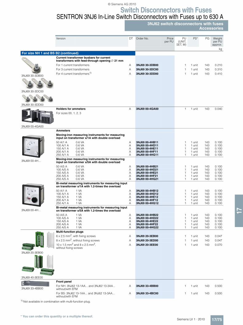
Switch Disconnectors with FusesSENTRON 3NJ6 In-Line Switch Disconnectors with Fuses up to 630 A
3NJ62 switch disconnectors with fusesAccessories
17/75Siemens LV 1 · 2010* You can order this quantity or a multiple thereof.
17
1) Not available in combination with multi-function plug.
Version DT Order No. Priceper PU
PU(UNIT,
SET, M)
PS* PG Weightper PU
approx.
kg
For size NH 1 and BS B2 (continued)
3NJ69 30-3DB00
3NJ69 30-3DC00
3NJ69 30-3DD00
Current transformer busbars for current transformers with feed-through opening ∅ 21 mm
For 1 current transformers A 3NJ69 30-3DB00 1 1 unit 143 0.210
For 3 current transformers A 3NJ69 30-3DC00 1 1 unit 143 0.310
For 4 current transformers1) A 3NJ69 30-3DD00 1 1 unit 143 0.410
3NJ69 00-4GA00
Holders for ammeters
For sizes 00, 1, 2, 3
A 3NJ69 00-4GA00 1 1 unit 143 0.040
Ammeters
3NJ69 00-4H...
Moving-iron measuring instruments for measuring input on transformer x/1A with double overload
50 A/1 A 0.6 VA A 3NJ69 00-4HB11 1 1 unit 143 0.100100 A/1 A 0.6 VA A 3NJ69 00-4HD11 1 1 unit 143 0.100150 A/1 A 0.6 VA A 3NJ69 00-4HE11 1 1 unit 143 0.100200 A/1 A 0.6 VA A 3NJ69 00-4HF11 1 1 unit 143 0.100250 A/1 A 0.6 VA A 3NJ69 00-4HG11 1 1 unit 143 0.100
Moving-iron measuring instruments for measuring input on transformer x/5A with double overload
50 A/5 A 0.6 VA A 3NJ69 00-4HB21 1 1 unit 143 0.100100 A/5 A 0.6 VA A 3NJ69 00-4HD21 1 1 unit 143 0.100150 A/5 A 0.6 VA A 3NJ69 00-4HE21 1 1 unit 143 0.100200 A/5 A 0.6 VA A 3NJ69 00-4HF21 1 1 unit 143 0.100250 A/5 A 0.6 VA A 3NJ69 00-4HG21 1 1 unit 143 0.100
3NJ69 00-4H...
Bi-metal measuring instruments for measuring input on transformer x/1A with 1.2-times the overload
50 A/1 A 1 VA A 3NJ69 00-4HB12 1 1 unit 143 0.100100 A/1 A 1 VA A 3NJ69 00-4HD12 1 1 unit 143 0.100150 A/1 A 1 VA A 3NJ69 00-4HE12 1 1 unit 143 0.100200 A/1 A 1 VA A 3NJ69 00-4HF12 1 1 unit 143 0.100250 A/1 A 1 VA A 3NJ69 00-4HG12 1 1 unit 143 0.100
Bi-metal measuring instruments for measuring input on transformer x/5A with 1.2-times the overload
50 A/5 A 1 VA A 3NJ69 00-4HB22 1 1 unit 143 0.100100 A/5 A 1 VA A 3NJ69 00-4HD22 1 1 unit 143 0.100150 A/5 A 1 VA A 3NJ69 00-4HE22 1 1 unit 143 0.100200 A/5 A 1 VA A 3NJ69 00-4HF22 1 1 unit 143 0.100250 A/5 A 1 VA A 3NJ69 00-4HG22 1 1 unit 143 0.100
3NJ69 20-3EB00
3NJ69 40-3EE00
Multi-function plugs
6 x 2.5 mm2, with fixing screws A 3NJ69 20-3EB00 1 1 unit 143 0.047
8 x 2.5 mm2, without fixing screws A 3NJ69 20-3ED00 1 1 unit 143 0.047
10 x 1.5 mm2 and 8 x 2.5 mm2, without fixing screws
A 3NJ69 20-3EE00 1 1 unit 143 0.070
3NJ69 33-4BB00
Front panel
For NH: 3NJ62 13-1AA... and 3NJ62 13-3AA... without/with EFM
A 3NJ69 33-4BB00 1 1 unit 143 0.500
For BS: 3NJ62 13-1AA... and 3NJ62 13-3AA... without/with EFM
A 3NJ69 33-4BC00 1 1 unit 143 0.500
LV1_17.book Seite 75 Mittwoch, 16. Dezember 2009 4:15 16
© Siemens AG 2010
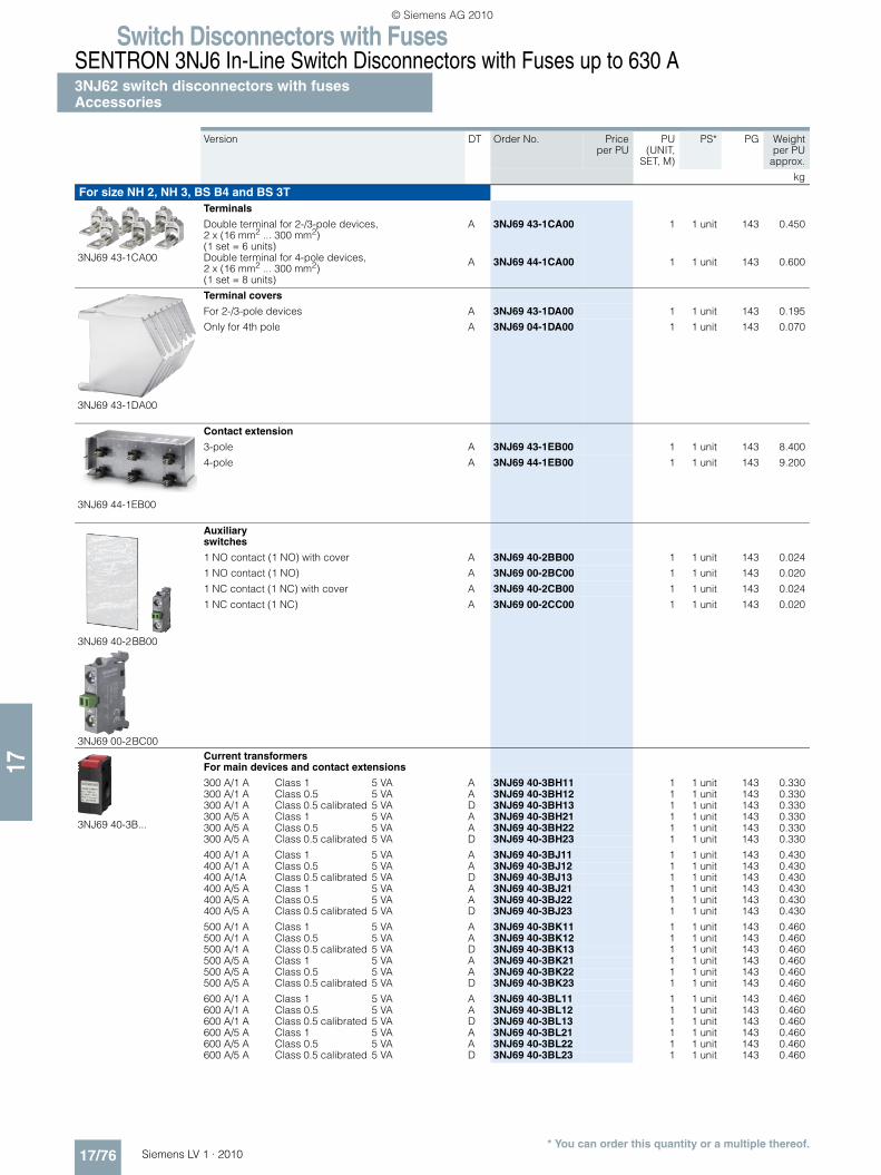
Switch Disconnectors with FusesSENTRON 3NJ6 In-Line Switch Disconnectors with Fuses up to 630 A3NJ62 switch disconnectors with fusesAccessories
17/76 Siemens LV 1 · 2010* You can order this quantity or a multiple thereof.
17
Version DT Order No. Priceper PU
PU(UNIT,
SET, M)
PS* PG Weightper PU
approx.
kg
For size NH 2, NH 3, BS B4 and BS 3T
3NJ69 43-1CA00
Terminals
Double terminal for 2-/3-pole devices, 2 x (16 mm2 ... 300 mm2)(1 set = 6 units)
A 3NJ69 43-1CA00 1 1 unit 143 0.450
Double terminal for 4-pole devices, 2 x (16 mm2 ... 300 mm2)(1 set = 8 units)
A 3NJ69 44-1CA00 1 1 unit 143 0.600
3NJ69 43-1DA00
Terminal covers
For 2-/3-pole devices A 3NJ69 43-1DA00 1 1 unit 143 0.195
Only for 4th pole A 3NJ69 04-1DA00 1 1 unit 143 0.070
3NJ69 44-1EB00
Contact extension
3-pole A 3NJ69 43-1EB00 1 1 unit 143 8.400
4-pole A 3NJ69 44-1EB00 1 1 unit 143 9.200
3NJ69 40-2BB00
3NJ69 00-2BC00
Auxiliary switches
1 NO contact (1 NO) with cover A 3NJ69 40-2BB00 1 1 unit 143 0.024
1 NO contact (1 NO) A 3NJ69 00-2BC00 1 1 unit 143 0.020
1 NC contact (1 NC) with cover A 3NJ69 40-2CB00 1 1 unit 143 0.024
1 NC contact (1 NC) A 3NJ69 00-2CC00 1 1 unit 143 0.020
3NJ69 40-3B...
Current transformers For main devices and contact extensions
300 A/1 A Class 1 5 VA A 3NJ69 40-3BH11 1 1 unit 143 0.330300 A/1 A Class 0.5 5 VA A 3NJ69 40-3BH12 1 1 unit 143 0.330300 A/1 A Class 0.5 calibrated 5 VA D 3NJ69 40-3BH13 1 1 unit 143 0.330300 A/5 A Class 1 5 VA A 3NJ69 40-3BH21 1 1 unit 143 0.330300 A/5 A Class 0.5 5 VA A 3NJ69 40-3BH22 1 1 unit 143 0.330300 A/5 A Class 0.5 calibrated 5 VA D 3NJ69 40-3BH23 1 1 unit 143 0.330
400 A/1 A Class 1 5 VA A 3NJ69 40-3BJ11 1 1 unit 143 0.430400 A/1 A Class 0.5 5 VA A 3NJ69 40-3BJ12 1 1 unit 143 0.430400 A/1A Class 0.5 calibrated 5 VA D 3NJ69 40-3BJ13 1 1 unit 143 0.430400 A/5 A Class 1 5 VA A 3NJ69 40-3BJ21 1 1 unit 143 0.430400 A/5 A Class 0.5 5 VA A 3NJ69 40-3BJ22 1 1 unit 143 0.430400 A/5 A Class 0.5 calibrated 5 VA D 3NJ69 40-3BJ23 1 1 unit 143 0.430
500 A/1 A Class 1 5 VA A 3NJ69 40-3BK11 1 1 unit 143 0.460500 A/1 A Class 0.5 5 VA A 3NJ69 40-3BK12 1 1 unit 143 0.460500 A/1 A Class 0.5 calibrated 5 VA D 3NJ69 40-3BK13 1 1 unit 143 0.460500 A/5 A Class 1 5 VA A 3NJ69 40-3BK21 1 1 unit 143 0.460500 A/5 A Class 0.5 5 VA A 3NJ69 40-3BK22 1 1 unit 143 0.460500 A/5 A Class 0.5 calibrated 5 VA D 3NJ69 40-3BK23 1 1 unit 143 0.460
600 A/1 A Class 1 5 VA A 3NJ69 40-3BL11 1 1 unit 143 0.460600 A/1 A Class 0.5 5 VA A 3NJ69 40-3BL12 1 1 unit 143 0.460600 A/1 A Class 0.5 calibrated 5 VA D 3NJ69 40-3BL13 1 1 unit 143 0.460600 A/5 A Class 1 5 VA A 3NJ69 40-3BL21 1 1 unit 143 0.460600 A/5 A Class 0.5 5 VA A 3NJ69 40-3BL22 1 1 unit 143 0.460600 A/5 A Class 0.5 calibrated 5 VA D 3NJ69 40-3BL23 1 1 unit 143 0.460
LV1_17.book Seite 76 Mittwoch, 16. Dezember 2009 4:15 16
© Siemens AG 2010

Switch Disconnectors with FusesSENTRON 3NJ6 In-Line Switch Disconnectors with Fuses up to 630 A
3NJ62 switch disconnectors with fusesAccessories
17/77Siemens LV 1 · 2010* You can order this quantity or a multiple thereof.
17
Version DT Order No. Priceper PU
PU(UNIT,
SET, M)
PS* PG Weightper PU
approx.
kg
For size NH 2, NH 3, BS B4 and BS 3T (continued)
3NJ69 00-4GA00
Holders for ammeters
For sizes 00, 1, 2, 3
A 3NJ69 00-4GA00 1 1 unit 143 0.040
Ammeters
3NJ69 00-4H...
Moving-iron measuring instruments for measuring input on transformer x/1A with double overload
300 A/1 A 0.6 VA A 3NJ69 00-4HH11 1 1 unit 143 0.100
400 A/1 A 0.6 VA A 3NJ69 00-4HJ11 1 1 unit 143 0.100
500 A/1 A 0.6 VA A 3NJ69 00-4HK11 1 1 unit 143 0.100
600 A/1 A 0.6 VA A 3NJ69 00-4HL11 1 1 unit 143 0.100
Moving-iron measuring instruments for measuring input on transformer x/5A with double overload
300 A/5 A 0.6 VA A 3NJ69 00-4HH21 1 1 unit 143 0.100
400 A/5 A 0.6 VA A 3NJ69 00-4HJ21 1 1 unit 143 0.100
500 A/5 A 0.6 VA A 3NJ69 00-4HK21 1 1 unit 143 0.100
600 A/5 A 0.6 VA A 3NJ69 00-4HL21 1 1 unit 143 0.100
3NJ69 00-4H...
Bi-metal measuring instruments for measuring input on transformer x/1A with 1.2-times the overload
300 A/1 A 1 VA A 3NJ69 00-4HH12 1 1 unit 143 0.100
400 A/1 A 1 VA A 3NJ69 00-4HJ12 1 1 unit 143 0.100
500 A/1 A 1 VA A 3NJ69 00-4HK12 1 1 unit 143 0.100
600 A/1 A 1 VA A 3NJ69 00-4HL12 1 1 unit 143 0.100
Bi-metal measuring instruments for measuring input on transformer x/5A with 1.2-times the overload
300 A/5 A 1 VA A 3NJ69 00-4HH22 1 1 unit 143 0.100
400 A/5 A 1 VA A 3NJ69 00-4HJ22 1 1 unit 143 0.100
500 A/5 A 1 VA A 3NJ69 00-4HK22 1 1 unit 143 0.100
600 A/5 A 1 VA A 3NJ69 00-4HL22 1 1 unit 143 0.100
3NJ69 40-3EC00
3NJ69 40-3ED00
3NJ69 40-3EF00
Multi-function plugs
8 x 2.5 mm2, with fixing screws A 3NJ69 40-3EC00 1 1 unit 143 0.147
8 x 2.5 mm2, without fixing screws A 3NJ69 40-3ED00 1 1 unit 143 0.147
12 x 1.5 mm2 and 8 x 2.5 mm2, without fixing screws
A 3NJ69 40-3EF00 1 1 unit 143 0.170
3NJ69 43-4BB00
Front panel
For NH: 3NJ62 23-1AA... and 3NJ62 23-3AA... without/with EFM
A 3NJ69 43-4BB00 1 1 unit 143 0.700
For BS: 3NJ62 23-1AA... and 3NJ62 23-3AA... without/with EFM
A 3NJ69 43-4BC00 1 1 unit 143 0.700
For NH: 3NJ62 33-1AA... and 3NJ62 33-3AA... without/with EFM
A 3NJ69 53-4BB00 1 1 unit 143 0.700
For BS: 3NJ62 33-1AA... and 3NJ62 33-3AA... without/with EFM
A 3NJ69 53-4BC00 1 1 unit 143 0.700
LV1_17_10.fm Seite 77 Donnerstag, 21. Januar 2010 3:12 15
© Siemens AG 2010

Switch Disconnectors with FusesSENTRON 3NJ6 In-Line Switch Disconnectors with Fuses up to 630 A3NJ62 switch disconnectors with fusesAccessories
17/78 Siemens LV 1 · 2010* You can order this quantity or a multiple thereof.
17
Version DT Order No. Priceper PU
PU(UNIT,
SET, M)
PS* PG Weightper PU
approx.
kg
Common accessories
3NJ69 16-4EA00
Busbar covers
Mounting height 200 mm, IP20 A 3NJ69 16-4EA00 1 1 unit 113 0.472
3NJ69 00-4CB00
Blanking covers
Mounting height 50 mm, IP41 A 3NJ69 00-4CB00 1 1 unit 143 0.800
3NJ69 15-3BA00
Connection modules
For power takeoff from field distribution bus up to 400 A A 3NJ69 15-3BA00 1 1 unit 113 1.524
3NJ69 00-4FB00
3NJ69 00-4FC00
Guide rails
Depth 200 mm (1 x left and 1 x right) C 3NJ69 00-4FB00 1 1 unit 143 1.300
Depth 400 mm (1 x left and 1 x right) C 3NJ69 00-4FC00 1 1 unit 143 1.800
NH fuse puller tongs
For NH00 C XPT:8PT9624 1 1 unit 195 0.497
For NH1, 2, 3 C XPT:8PT9625 1 1 unit 195 0.505
LV1_17_10.fm Seite 78 Donnerstag, 21. Januar 2010 3:12 15
© Siemens AG 2010
Recommended