• o -. . - :. :+_.+:_.: + _ . ++.+-+_,..-+
_ ..
- nGN...m_
- . +'k-'_i_
- SNAP-8 TOPICAL MATERIALSREPORTFOR 1962
VOL. tll - SNAP-8 MERCURYCORROSION AND MATERIALS!_ESEARCH
, A Reportto.
National Aeronauticsand Soace_:!m.inlstration
https://ntrs.nasa.gov/search.jsp?R=19650012957 2018-05-31T01:56:22+00:00Z

Aerojet General Corporation Report No. 2517, Vo!. III
Aerojet General Nucleonics Report No. AN-TM-192Subcontract 274949, under NAS 5-417
AGNSNAP-8 MERCURY CORROSION AND MATERIALS RESEARCH
Topical Report
For the P6_-iod Ju**e, 1960 to December, 1962
M. F. Parkman, B. E. Farwell, D. K. Wha!ey, and R. V. Arabian
H/ja f_nager
!ppSWd_enceDiv_ionAEROJET-6EHEIIAi. NUCLEOMiCSA .SUBSIDIARY OF AEROJET. GENERAL CORPORATION
This re!,c_t is submz_t_d in pP_tlal fulfillment of National Aeronautics and
Space Administration Contract NAS 5-417. Thi_ vulua_ i= the third of four
volumes that comprise the complete report.
}
1965012957-002
FOREWORD
This work was conducted from July, 1960 to December, 1962 at
-. Aerojet-General Nucleonics, San Ramon, California, as part of the SNAP-8
_terials Research Program, under Subcontract 274949 to Aerojet General
Corporation, Azu_a, California. The SNAP-8 Division of Aerojet General
Corporation is developing the SNAP-8 Power Conversion System for the
National Aeronautics and Space Administration under Contract NAS 5-417.
The work was carried out at different times by the following
personnel:
Project Engineers, San Ramon SNAP-8 Materials Research
Activities: J. R° Payne, M. F. Parkman, and R. S. Carey.
Task Engineers of work reported herein:
M. F. Parkman and D. K. Whaley; B. E. Farwell and D. K. Whaley;
B. Farwell and R. V. Arabian.
Experimental Activities_
L. A. Rice, R. Rennolds, R. W. Johnson
Metallography:
G. Lundeen and W. Wandry.
This report was compiled by P. F. Young, R. V. A1abian, and M. F. Parkman.
ii
1965012957-003
Mercury corrosion of Haynes Ai_oy No. 25, Type 405 stainless steel,
AM350, 9Cr-iMo and Cb-IZr thermal convection capsules was investigated
between i000 an_ I0,000 hours at I025°F and llO0°F and between 500 and
2000 hours at 1175° and 1250°F. Isothermal capsules of Haynes 25 and Type
405 stainless steel were operated for 5000 and i000 hours. Thermal
convection capsules were heated at the bottom and cooled at the top to
create a thermal gradient of 85° to 150°F.
Penetration of the bottom half of the Haynes 25 thermal convection
capsules increased with time and temperature up to 2½ mils maximum at i175°F.
The corrosion layer spalled off the 1250°F capsules. A mass transfer
deposit that increased in amount with time and temperature formed along the
'top half of the capsules. Very little corrosion of the isothermal
capsules occurred. Tensile specimens machined from the Haynes 25 capsules
after test were pulled and indicated that the material age hardened after
exposure at 1175 ° and 1250°F.
Small mass transfer deposits occurred along the top half of the Type
405 stainless steel capsules, increasing in amount With time and temperature,.
but were much smaller than in Haynes 25 capsules. The bottom halves dissolved
evenly with no porous layer formed but with surface roughening'and inter-
granular penetration up to I mil_
Similar results occurred with AM 350 and 9Cr-IMo with the former about
the same as Haynes 25 and the latter similar to Type 405 stainless steel.
Cb-iZr exhlb!ted no detectable corrosion. __._
iii :_
-%
1965012957-004
Stress rupture properties of AM 350 in the solution annealed and
equalized conditions were measured at 1300°F after eging at different
temperatures.
iv
1965012957-005

TABLE OF CONTENTS
FOREWORD......................................................... ii
ABSTRACT ......... ................................................ ill
TABLE OF CONTENTS .......... ................................... --. v
LIST OF FIGURES ................................................... vii
LiST OF TABLES. .............................................. •••• ix
i. INTRODUCTION ............................................. -• 1
II. TEST PLAN ................................................... 3
Ill. APPARATUS AND EXPERIMENTAL PROCEDURES FOR CORROSION TESTS.. 9
A. CAPSULE" DESIGN AND FABRICATION ..... ;................. 9
i. Haynes 25 and _Tpe 405 Stainless Steel ........ . II
2. Cb- iZr ......................................... . 15
3. AM 350 and 9Cr-iMo ...... ........................ 15
- B. FURNACE DESIGN AND OPERATION ........................ _ 15
C. TEST METHODS ............. ........................ :.•. 20
I. Capsule Decontamlm tlon and Sampling ............ 20 ;
.2. Capsule Diameter Measurements .................. 20
3. Hardness Measurements .......................... 20
4. Tensile Testing ................................. 22
IV. RESULTS OF CORROSION TESTS ................................. 27
A. HAYNES ALLOY NO. 25 .................................. 28
I. Capsules Exposed at i025°F ..................... 28
2. Capsules Exposed at ll00°F ..................... 36
3. Capsules Exposed at I175°F ..................... 46
4. Capsules Exposed at !250°F ..................... 52
5. Corrosion Product Analysis ...................... 58
6. Mechanical Properties .......................... 58
B. TYPE 405 STAINLESS STEEL ........ •..................... 58
I. Capsules Exposed at I025°F ..................... 58
2. Capsule.° Exposed at ll00°F ..................... 62f
C. AM- 350 ALLOY ......................................... 70
D. 9%Chromlum-l% Molybdenum Alloy ....................... 72
E. Columblum-l% Zirconium Alloy ....... •................. 74
25
1965012957-006

_Table of Contents Continued)
P_.a__
V. DISCUSSION OF HAYNES 25 CORROSION TESTS.................... 76
A. CORROSION............................................. _rID
B. _C _LANICALPROP}_RTIES................................. 77-.'.:.
.." v_. _C_CAL P_OP_nESOFA_350.............................81
y
-i vi
1965012957-007
List of Fiu_
Number Title Page. _
i. Operation Principle of Natural Convection Capsule i0
2. Capsule Design 12
3. Fils I Machined Capsule Parts 13
4. Semiautomatic Welding of Capsule 14
5_ Evacuating and Seal_ug Vacuum Type Capsules 16 ;
6.. Corrosion Capsule Furnace 18 ,
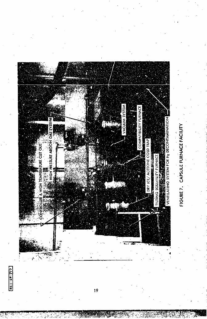
7. Capsule Furnace Facility 19
8. Capsule Decontamination Still 21
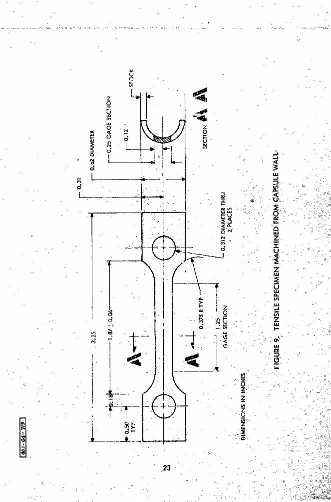
9. Tensile SpeclmenMachlned from Capsule Wall 23
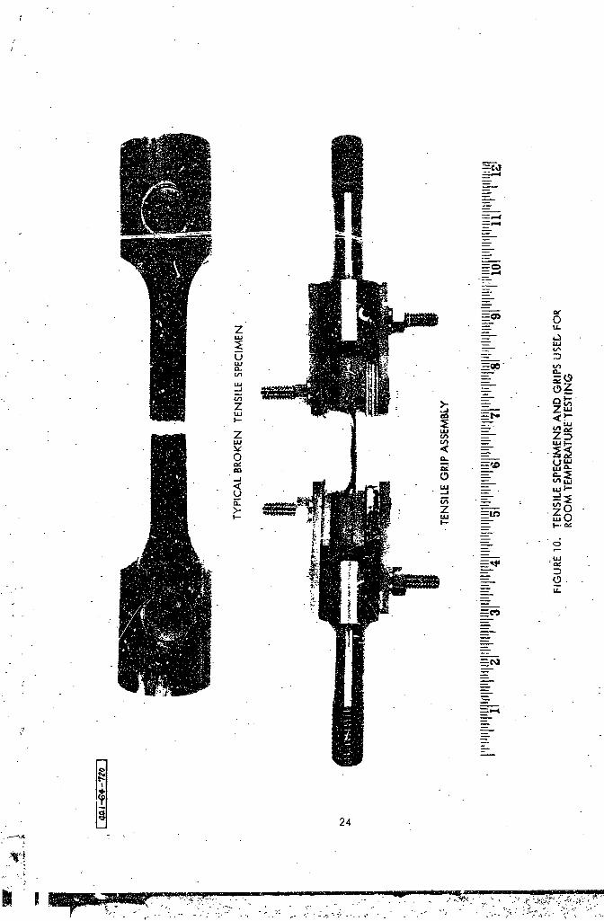
• i0. Tensile Specimens and Gripe Used for Roor_ Temperature Testing 24 i
ii. Tensile Specimens and Grips Used for Elevated Temperature 25 "
Testing
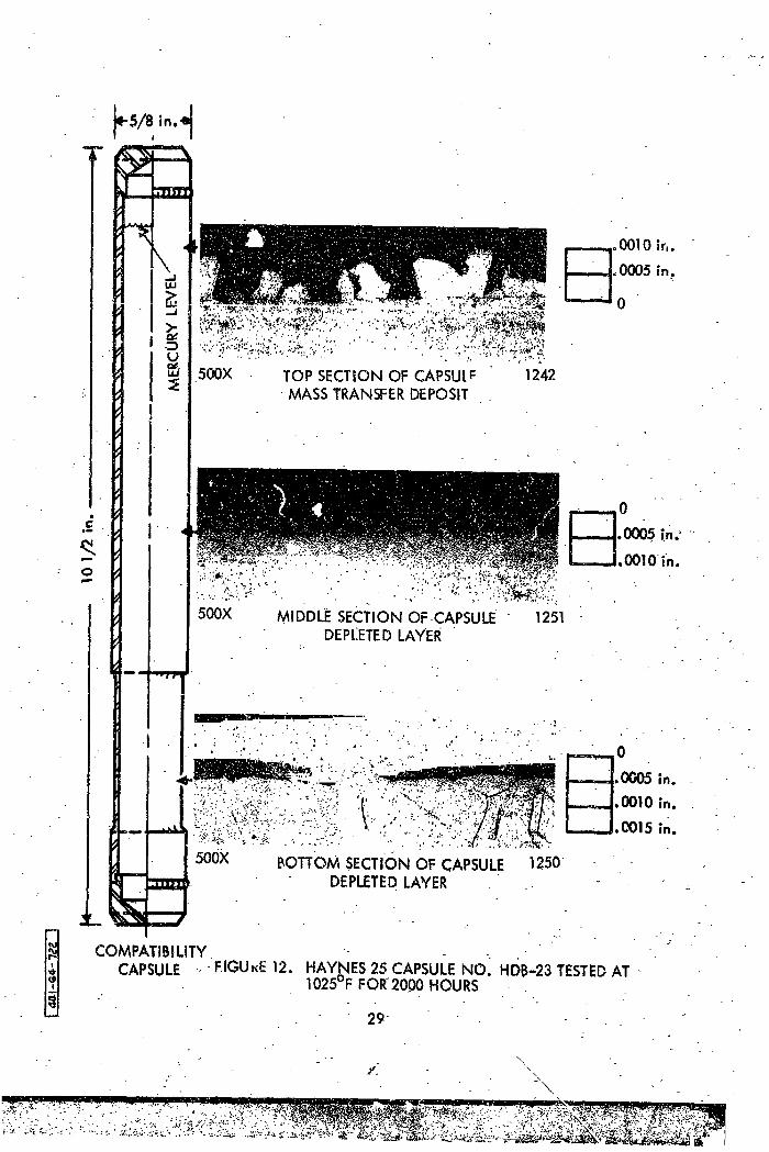
• 12. Haynes 25 Capsule No. }DB-23 Tested at i025°F for 2000 Hours 29 _
13. Haynes 25 Capsule No. HEB-7 Tested at I025°F for 5000 Hours 31
14. Haynes 2_ Capsule No. HDBW-_Tested at I025°F for 10,000 Hours 33
15. Microhardness Curcey, Haynes 25 Exposed" to Mercury at i025°F 35
16. }hynes 25 Capsule No. HDA-19 Tested at llO0°F for 5000 Hours 37
17. Haynes 25 Capsu!e No. HDA-9 Tested at ll00°F for 10,000 Hours 39
18 Haynes 25 Capsule No. HDC-14 Tested at II00°F for 5000 Hours 41
19. Haynes 25 Capsule No.H DC-ifTested at llO0°F for i0,000 Hours 43L
20. M/crohardness Survey, Hayne_ 25 Exposed to Mercury a_ !100°F 45
21. Haynes 25 Capsule No. UDB-3OTected at i175°F for 2000 Hours 47
22. Haynes 25 Capsule No_D_-37 Tested at i175°F for 5000 Hours 49 ,_
23. Microhardness Survey, Haynes 25 Expo_d to Mercury at i175°F 51 _
24. Haynes 25 Capsule No. HDA-42 Tested at 1250°F for i000 Hours 53[
25. Hayneu 25 Capsule No_DBW-46 Tested at 1250°F for 2000 Hours 55
26. Microhardness Survey, Haynes 25 Exposed to Mercury at 12500F 57
27. Type 405 Stainless Steel Capsule }_. 4BA-8 Exposed at 59 :I025°F for 5000 hours
28. Type 405 Stainless Steel Capsule No. 4BB-13 Exposed at 61 _"
I025°F for I0,000 Hours ";%
29. Type 405 Stainless Steel Capsule No. 4BA-4 Tested at _lO0°F 63 "!_
for 5000 Hours ._-_-_
1965012957-008

J/!
Figures (continued)
Number Title Page
30.. Type 405 Stainless Steel Capsule No, 4BA-! Ex-2osed at 65ll00°F for i0,000 Hours
31. Type 405 Stainless Steel Capsule with ColumbtumStrip 67Tested at iI00°_ for 2000 Hours
32, Mi_crohardnessSurvey, _ype 405 Stainless 3reel _xposed 68tO Mercury at I025°F
33. Microhardness Survey, Type 405 S_alnless Steel Exposed 69tO Mercury &t II00-F = '
34. &-350 Capsules Tested at 1250°F for 500 Hours 71
35. 9Cr-lldoCapsuleNo. 9AA-71 with ColumbiumStrlp Tested 73
" a_ 1250°F for 500 Hours .
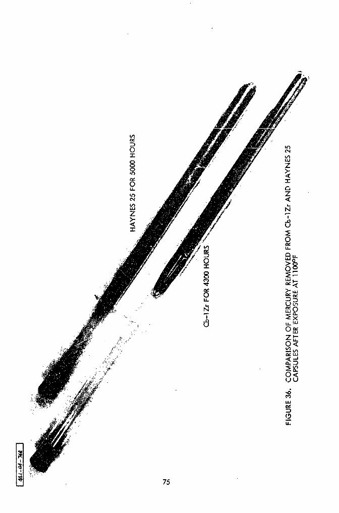
'_ _ 36.- Comparfson of Herc.ry P,emov_£_om Cb-IZr and Haynes 23 _-75Capsules after Exposure at IIO0_F
37. Knoop Hardness versus Exposure Time for Haynes 25 78
38. Tens£1e Elongation versus Knoop Hardness:for Haynes 25 80
Tensile Test-Specimens
1965012957-009

List of Tables
i. Susm_ry of Capsule Tests .• 1
2. Materlal_ Data 6
3. S1mmmry of Test Results _rom Hayn.es 25 CompatibilityCapsules Exposed at 1025 F 34
4. Summary of Test Results from Haynes 25 Compatlbil_ty
C_psules Exposed at ll00°F _4 _
5. :S_mary of Test Results from Haynes 25 Compatlbi!,ity
Capsules Exposed to 1175OF _ " 50 _,
6. -Summary of Test Results _rpm Haynes 25 Compatlbility , _. :
Capsules Exposed at 1250-F _ 56 _.
7. SOlUtion Annealed AN-350 Rupture Tests _t 1300°F 82 ,-;v
• J
2--"
1965012957-010
I. INTRODUCTION
This is a report of materials research in support of the SNAP-8 project
covering the period June 1960 through December 1962. It includes work to
study liquid mercury cGLzosion of Ilaynes 25, Type 405 stainless steel, AM-350,
9Cr-iMo, and Cb-IZr in capsules, and to _easure the mechanical properties of
AM-350. Concurrent tasks to measure the solubility of elements in Hg and
to study the effects of additives on mercury pool boiling ileat transfer are
reported separately. 1'2'3
At the start of the SN_P-8 program, inform4tion was available 4'5 to
make a preliminary selection of alloys from the standpoint of resistance to
mercury corrosion. Work was to be based largely on SNAP-2 technology so
Haynes 25 was the alloy of prime interest. Early work at General Electric4
Company showed that the ferritic alloys had good resistance to mercury
corresion below I000°, so Type 405 stainless steel was also selected _or
investigation as representative of those alloys and because of m_nlmal welding
problems.
In ].962, information from this program and from concurrent programs
at NASA-Lewis Research laboratory and Thompso_ Ramo Wooldridge indicated
* See Table 2 for nominal compositions of materials.
1965012957-012

that Haynes 25 would not be satisfactory for long-time use in the high
"_e_perature parts of the SNAP-8 system 5o work was started With 9Cr-iMo,
AM-350, and Cb-lZro 9Cr-iMo was of interest to replace Haynes 7) as nile
SNAP-8 reference material because it was the ferritic alloy with the least
amount of Cr t>mt would maintain oxidation resistance at 1300°F. AM-350
was indicated to be a promising alloy irom capsule testing at 'Lewis Research
Center. Cb-iZr was indicated to be completely resisuant to mercury corrosion
at SNAP-8 temperatures and was of interest as a backup.
The objective of the capsule tests was to investigate mass transfer,
stress corrosion, mode of corrosion attack, structure and composition of
mass transfer products, and change in mechanical properties of the alloy_
during exposure to Hg between 1025 ° and 1250°F up to i0,000 hours.
1965012957-013

II. TEST PLAN
A summary of the test plan is shown in Table I. Three t_-pes of cap-
sules werc made from 5/8 in. OD tubing (see Section III-A for details). All
were nearly filled with Hg, and operated with either argon or vacuum in the
remaining space. Types A and B were about ii in. long, were heated on the
bottom half at,_dcooled on the top half to induce a thermal convection cir-
culation of the Hg. The Type C capsules were 5 in. long and were operated
isothermally to distinguis h the effects of circulating and static Hg.
Capsules of Type 405 stainless steel were operated only at 1025 ° and
!100°F because the creep strength was not adequate to withstand the vapor
pressure of _8 at the higher temperatures.
Mass transfer potentisl was to he measured by observing the amount of
corrosion at the hot _bottom) end and the amount of deposition at the cold
(top) end. The amount an4 mode of corrosion was to be determined by
microgra_hic examir_tion and diametral measurements before and after the
run.
Stre__s corrosion effects were to be measured by machining thin walls
in some of the capsules (Types B and C). A wide range of stresses resulted
due to the reduced wall thickness and different internal pressures at
dLffe_en_ temperatures.
3 :
-:.L.--'_7-..... -,r_'-'- .... _ .--;,_e.T,_.:_;_i -. '.. .....
1965012957-014


}_chanical property effects were to be determined by measuring
the hardness of the tubing and machining tensile specimens from the
capsule vails after the runs.
Some mass transfer deposits wer_ to be analyzed by X-ray diffraction
and emission spectrography to determine structure and composition.
Haynes 25 and Type 405 stai_lless steelwere replace_ as prime SNAP-8
cand_.d_tes by 9Cr-IMo and AM-350 part way through the program. It was
decided to cnntinue the capsules that were running to their 10_000-hour
scheduled shutdown bus the amount of analysis was curtailed. Thus some
of the objectives, particularly on the longer time capsules, were not
completed on those alloys.
The 9Cr-IMo, AM-350, and Cb-lZr capsules were all Type A and only
qualitative compatibility information was sought.
No tensile or stres_ rupture data were available for the solution
annealed AM-350 at SNAP-8 temperatures so sheen speclmen_ were tested to
obtain these data and compared to specimens in the equal_zed condition.
5
1965012957-016
!e
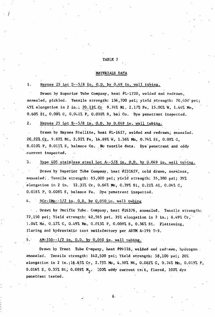
TABLE 2
MATERIALS DATA
I. Haynes 25 Lot D--5/8 in. O.D. by 0.49 in. wall tubing. "
Drawn by SuPerior Tube Company, heat #L-1720, welded and redrawn,
annealed, pickled. Tensile strength: 136,700 psi; yield strength: 70,400 psi;
45% elongation in 2 in.; 20.13__Cr 9.74% Ni_ 2 17_ Fe, 15 OG% W, 1.44% Mn,"
0,60% Si, 0.08% C, 0.O1i% P, 0.010% S, bai Co. Dye penetrantinspected.
2. Haynes 25 Lot E--5/8 in._O.D, bY 0.049 in_ wall tubing.
Drawn by Haynes Stellite, heat #L-1627, welded and redrawn_ annealed.
' 20.227_.C_ 9.82% Ni, 2.3-i% Fe, 14.89% W, 1.58% Mn, 0.74% Si, 0.09% C,
0.010% P, 0.011% S, balance Co. No tensile data. Dye peuetrant and eddy
current inspected.
3. l_pe 405 staln!ess steel Lot A--5/8 in. O.D. by 0.049 in..wall tubing.
Drawn by Superior Tube Company, heat _#23162X, cold drawn, seamless, ._
annealed : Tensile strength: 65,000 psi; yleld strength: 35,300 psi; 39%
_elongation in 2 in. 12.31% Cr, 0.66% Mn, 0.39% Si, 0.21% AI, 0.04% C,
0;016% P, 0.008% S, balance Fe. Dye penetrant inspected.
4. 9Cr-IMo--I/2 in. O.D. by 0.050 in. wall tubing
Drawn by Pacific Tube Company, heat #16376, annealed Tensile strength:
72,150 psi_ Yield strengtl_: 42,565 psi. 35% elongation in 2 in.; 8.49% Cr,
1.04% Mo, 0.12% C, 0.49_ Mn, 0.013% P, 0.009% S, 0.36% S%. Flattening,
flaring and hydrostatic test satisfactory per ASTM A-199 T-9.
5. AM-350--I/2 in. O.D. by 0.050 in. wall tubing."_~
Drawn by Trent Tube C_mpany, heat #99118, welded and redrawn, hydrogen
annealed. Tensile strength: I_2,500 psi; Yield strength: 58,100 psi.; 20%
elongation in 2 in.;16.65 % Cr, 2.75% Mo, 4.38% Ni, 0.082% C, 0.74% Mn, 0.019% P,
0.016% S, 0.35% Sl; 0.089% N2. 100% eddy current teft, flared, 100% dye
penetrant tested.
• ..
1965012957-017

(Table 2 continued)
6. Cb-_Zr--i/2 in. O.D. by 0.49 in. wall tubin G .
Supplied by Wah Chang Corporation stress_ relieved at 1850°F. 98.75% Cb,
1.15% Zr, 30 ppm C, 94 ppm N, 180 ppm O.
7. Cb--0.06 in. sheet
Supplied by Wah Chang Corporation, heat #9-4432-Cb. Ingot hardness
range: 55.1-63.3 BHN. Ingot chemistry (ppm):
Element ' To_____m_ Element fop (ppm)
A1 3s- B <1C <30 Cd <5
Cr <20 Cu <40
Fe . = .. 2100 H2 5 -
Hf," <80 _ <20
Mn - '_.20 14o <20
N2 _ 56 Ni -<20 ":
02 <50 Pb <.20
Sf 140 _ Sn <20
Ta <500 : Ti <150
V <20 W <300 "
Zn . <20 Zr <.500
- 7
m mmmm_mmlm*,E.em_ m Mm _ p
] 9650] 2957-0] 8

/
°-
L--
.- V
_-,_ -'- -
_,_ - _ .. ," _ -,
1965012957-019

-:
III_ APPARATUSAND EXP_II_,NT_. PROCE_URE_. ..
A. CAPSULE DESIGN AND FABRICATION
The principle of the capsule design and test method is illustrated _'
in Figure i. A furnace (d'escrlbedin Section B) contained two 6 in. dia.
x 6 in. long blocks, each wish 19 holes and separated by insulation. The
bottom block was enclosed in clam shell heaters and the top block was unheated.
Capsules were mounted in the holes so that the bottom half w_s heated by
the bottom block. The AT between top and bottom of capsule varied between
80° and 150°F depending on the nominal temperature, the type.of umterial, and
the length of time since s":artup. This situation created a natural convection
flow p_ttern as shown in F_gure I. The liquid being heated at the bottom
of the capsule ascended next to the wall and descended at the axis. The
wall along the bottom half of the capsule dlssblved into the rising film of
liquid. When this film reached the upper half and coc!ed, she liquid became
supe_s_urated and the solute preclpitated-to form a d_po_It on the wall or
a powder in the llquid. By keepln_ all capsules under a similar_T, it
was expected thatrelstive differences between alloys could be measured.
This flow System had been studied by Hartnett, Welch, _nd
Larson6 at a length-to-dlameter ratio of.21. Heat transfer had been
correlated against a modified GzashofoPrantl number. The Types A and B
capsules were selected with this same ratio becavse it was hoped-that
_
1965012957-020

/
f
IMASS
TRANSPORT
DEPOSIT "COOt.ING
BLOCK
'_ T BETWEEN TOP ANDBOTTOM TYPICALLY |- """-"_- • -----"""......--- ON
: 8o-isooFON5/8!'ODx I0" C_,'SULES
.. _c.
| A"I / HEATING
BLOCKi
REGION OF _ --MAXIMUM
|
CORROSION
; FIGURE 1., OPERATION PRINcIPkF. OF NATURAL CONVECT ION cAPSULE, :
10
1965012957-021
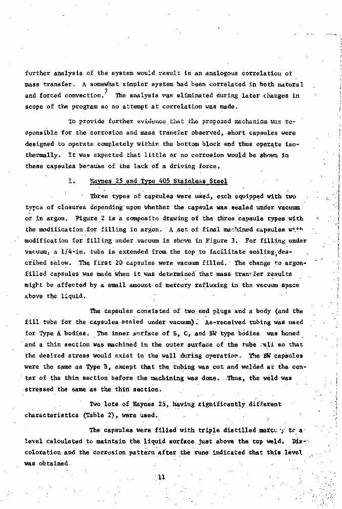
further analysis of the system would result in an analogous correlation of
mass transfer. A somewhat simpler system bad been correizted in both natural
and forced convection. 7 The analysis was eliminated during later changes in "
scope of the program so no a_tempt at correlation was made.
To provide further ev_u_n_ L.._L the propo._ed-^_-_.,=..._............. .:a_ _--._. l
sponsible for the corrosion and mass transfer observed, short capsules were
designed to operate completely within the bottom block and thus operate iso-
t_rmally. It was expected _Im,t little or no corrosion would be shown in
these capsules be_.ause of the lack of a driving force. *
i. _U_ynes 25 and Type 405 S,tainle._sSteel " :
: Three types of capsules-Were used._ each equipped with.=t_o :.__Itypc_ of closures depending upon whether the capsule was sealed under vacuum i
or in argon. Figure 2 is a -composite drawing of the three capsule types •with '-_ i
the modificatlon,'fo r filling in argon, A set of final machined capsules w.____h ,
modificatlon for filling under vacuum is sho,_n in Figure 3. For filllng, under .-
vacuum, a i/4-in, tube iS extended from the top to facilitate sealing_'des-
cribed below. Th_ first 20 capsules were vacuum filled. _ The change to argon- ' "
filled capsules was made when it was determined" that mass transfer results "
migb_t be affected by a small amount of mercury refluxing in the vacuum space "_.{
above the liquid.
The capsules consisted of two, end plugs and a body (and tlie "
fill tube for the capsules. .seaied under vacuum). As-recelved tubing Was used "
for Type A bodies, The inner _st_rfaceof B3 Ci and BW type b_dies was honed
and a thin section was machined in the outer surface of the tube :_all so t|mt
the desired stress would exist in the wall during operation. The BW capsules
were the same as_ Type B, except that the tubing was cut and welded at the cen-
ter of the thin section before the machining w_s done. .Thus, the wdid was •
stressed the same as the thin _section. .
Two lots of.llaynes:25, havlng _igntficant!y different "
characteristics (Table 2), wets Used. , : .- -. -.
The capsules were• fil.led with trlp,le dlszilled .mergu ")"tca
level calculated to maintain the llquid sarface: Just above the top- weld. D_.s-:.
Coloration and the corrosion pattern'.after the runs indlca_ed that thls levei -
was obtained.
] 9650 ] 2957-022
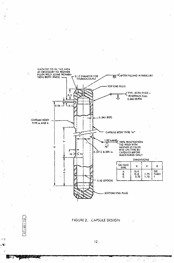
,._.ACH!NEOD IN _H!S _*RS:AAS NECESSARYTO PROVIDE
FLUSHWELD JOINT PREPARA- 0.13 DI_,_ETER FOR ....'---'-'Z_'"_AFTER FILLING W/MERCURY
TION (BOTh ENDS) THERMOCOUPLE/,/,,_ vf
PLUG
BOTH ENDS -PENETRATEFULL
"-" 0.043 DEPTH
_0.06
(REF)CAPSULEBODYTYPEA ANt:)
.i--.--!
J CAPSULEBODY TYPE "A"I>. l/_2 tAN[ 100% PENETRATION
TIG WELDWITHx 75° HAYNES 25 FILLER
Z-'-_ , I ROD ON TYPEBW
16 _>!le'_161 0.005 ;n. CAPSULESBEFORE,_ . j MACHINING ONLYJ J
u I DIMENSIONS
c L_. TYPE
"- 1o.oIi 10.0 I 1.75
-- 0,62 (STOCK) j 3.75 1.75
BOTTOM END PLUG
1-
FIGURE2 CAPSULEDESIGN
; - °
"' 12.
]
• . - -. - .. ....
1965012957-023

1965012957-024
FIGURE 4. SEMIAUTOMAT!C WELDING OF CAPSULE
s
.- ,...___:_; - :.._ • .- _,
1965012957-025

Capsules were fabricated and prepared as follows:
i) Cut lengths of tubing from different lots, as shown
in Table !. Number the lengths at random and record
to note original location from tubing. Cut short
samples with each length for pre-_est analysis or
reference, if needed after the run.
2) Rough machine parts.
3) Final machine parts.
4) Measure diameters and waI] thicknesses of bodies.
5) Degrease with trichlorethylene.
65 I_G weld with argon purge inside the capsule as
shown i_ Figure 4.
7) X-ray welds.
8) Etch Type 405 stainless in 2070B/_O3, 47o HF fo." 3
mlnutes at room temperature. Etch Haynes 25 the
same way except at 85°C:
95 Fill in air with triple distilled }{g.
Vacuum Type
I0) Evacuate until pressure of non-condensible gases
is below I x i0"4 torr (one to two days) (Figure 5a).
115 Pinch the small fill tube with a hydraulic C-clamp
(Figure 5b5. Preliminary tests established the
force necessary to form a vacuum tight seal.
12) Remove the capsule from the evacuation facility and
saw off the excess tul-e (Figure 5c) while holding
the vacuum with the C-clamp.
13) Weld across the end of the tube to seal the capsule.
(Figure 5d) then release the C-clamp.
Argon Type
105 Place capsules in vacuum glov@ box and evacuate
overnight.$
..... J I
1965012957-026

a. EVACUATING CAPSULES b.- PINCHING FILL TuBE
c. CUTTING OFF FILL TUBE d. WELDING FILL TUBE
FIGURE 5. EVACUATING AND SEALING VACUUM TYPE CAPSULES
16
. ';
"1g850"12g57-027

ii) Refill the glove box with argon and seal the cap-
sules in the glove box with a weld bead over the
small hole in the top (Figure 2).
2o Cb-IZr
Simple A-type capsules were made from 5/8 in. OD x I/B in.
wall tubing and closed with flat discs made from flattened tubing. T_ey
were filled and welded in the argon glove box.
3) AM-350 and 9Cr-IMo
Simple A-type capsules were made from 5/8 in. tubing withf
barstock used for end plugs. Some capsules 'contained columbium strips as
shown, ill Table io The capsules were depicted in some of the fi_ires showing
results; eog., Figure 31.
B. _NACE DESIGN AND OPERATION
Three furnaces, as shown in Figures 6and 7_were usedto contain
the capsules. A furnace consisted Of a cold wall pressure vessel containing
a 6 in. long mild steel blocksurrounded by an _rc-O-Ve _ heater coiled into
a helix. Another block was mounted directly above the heating block and was
separated from it by 1/2 in. of insulation. The remainder of ahe furnace was
iLlled with foamed silica insulation. The blocks contained 19 vertical holes
in which the capsules were m0_nted.
The furnaces could be operated up to 295 psia pressure or under
vacuum. All but short periods were conducted under vacuum less than i x lO-3torr
uslnga fore pump and dry ice/acetone cold trap.
The temperatures were measured with Aero Research 1/16oin. OD, _O-
insulated stainless steel sheathed Chrome l-Al_mel thermocoup!es. Conax g!ands
were used for heater and thermocouple feed throughs. The higher
temperatures also tended to result in a smaller_T. Ther_ocouples were
mounted in various locations in the blocks and in the holes at both ends of
2 capsules at opposite sides of the block. Te_iperatures were uniform radially
and the gradlent between top and bottom Of the Capsules varied between 85O
and 150 F. The tests were interrupted at 500 or 1000-hour intervals to
remove capsules, take diametral measurements, or start new capsules. The
wider gradient occurred at the start of each interval and narrowed after
17
1965012957-028

/

/
several days operation. The bottom of the c_psule remained at constant temoe-,:a-
ture and the top bec_me hotter during the period-, therefore, the nominal
temperatures listed in Table I apply to that part of 'the capsule undergoing
dissolution.
The temperature was concrolled by Wheelco l_odel 402 controller_-
us£._g a thermoc6upie placed between -he-.,leaL_n_ block and _- heater.
The furnaces orig_.nally were bullt with'a copper heating block
and an aluminum coolIng block to take.-advantage of their high thermal conductivlties.
A cap sule ieaked-Hg early in the il00°F run, forming a low m_iting eutectlc
with the :Cu a_d AI and destroying Some0f the capsules. The blocks were then
rep&aced with the-_iid steel blocks, -. _
•" - .-The *columbiumicapsu'ies were _rapped in zlrconi_n foil "_ mi_imize
--:- r.eact%onwith impu_ities in the_°furn_ce-atmosphere-during the run.. No-visible
_.d¢c0ntami_ation -Of the ;_b occ_rred..during the runs.- -.
.
i. Caps"-le Decontamination and Samplln_
_- Completed capsules _were-handied as follows:
I) Open. by sawlng-at the top until a small hole is
- .. made. -
2)i Pour Hg into- large tebt-tube •and. save
. 3) .Cut off ends of capsule..
- 4) Evaporate Hg fromcapsule bodies by molecular _- /
" dlstillatio, i_J200°F,) in the apparatus shown in
Figure 8. '-
-- _) " Evaporate Hg from testtube in the same apparatus
('certain capsules only.).
6) " Recover _-the" loose.,powd_r .f_om .Steps 4) and 5): and
-_: weigh.
_- 7) Measure capsU-le diame-ters. "
8) Cu¼ samples i_ormlc.rOgi'aphi_ examination.
9) Cut sample for tens_ile test (certain capsules only).
-_ 20
• t _ III I I ...... t I ' I JJ .... I
1965012957-031

o;
°
FIGURE8. CAPSULEDECONTAMiNATiONSTILLo
1965012957-032

!'
' 2. Capsule Diameter Measurements
The inside and outside diameters and wall t/alcknesses of
the'Haynes 25 and Type 405 stainless .steel"capsules ..weremeasured with a
mi_.rometer along 2 diameters_ Only one capsule exhibited any significant
change in die'deter while meaurements were made (2000-hr .capsules and under)
so no data will be shown. " One TYpe 405 stainless _ steel capsule _Ro. 4BB-2>
expanded about 9%, mostly during a short temperature excursion, so was re-c,
mov_ from test. :_ .- . . -_..c ".-
•. . 3. Hardness,:Measurement S
". " : _ -It was known that Hayne_ -25 would age harden during expo-
......sure_,:to-_emper_ttures -in the"sNAP-8_range. It was ,:hopdd.tha_ some correl,_rion
.... 5_n--m_C=ohardness a-nd elo,_io_ during a_tensile test _ould be found sc
'. . L_t'£utur.e-_esti"g_coui_d_'be-:s_p_ified. -A _Kentron Microha_dn_s _ester was
-- .used• to-mAke indentations ifi the m_crographic samples. :Readings Were_taken
at 120 O- i-ncer_ais--around the-'tubi.g; . L_pressi.ons _ere 'taken 'at _distances •
-- from-.the inslde and-outside of the-tubing as shown in _i_ree _'s_-rizing
the,_r_e@u!ts.: The avezage of-the-".3-Im_pressions at slmilardlsta'nces was used
to Obtain the valuee pi'btted. -" -; - _'
-'- '4.- Tensile •Testing _
" " It was decided to measure the effectsof exposure on the-
•Haynes 125-and_Type 405 stalnle'ss_steel by machlnlng tensile specimens from
_, the Walls of the tested capsules rather, t_,mn-use inserts. In this way. the
,"- effect of St'ress history woul:d-be included. This required a specla), speci-
e" :.- men, as shown, i_n Figure 9,. SpecL_l grips were also fabrlcated. Those used
_ _ _._or room tempe_rature testS are shown in-Fi_e lO and _hose _for.elevated tests• . .. .
in Figure ii. Tests were Perfo_ned, on as-reCeived tubing to check out the
grips-and to ob_in reference'-data. '-
-- • 22- .. .
1965012957-033


,!
1965012957-037

Iv. RESULTS
•The actual lengths of t_-'methat capsules operated were listed in Table
I. Representative data will be shown in the •following pages under divisions
of time and temperature. In ,general, duplicate capsules had nearly identical
results so are not shown. Data are not shown on welds sinceno effect differ-
ent from the base metal was noted. Phot6_icrograpks are not shown on some of
the shorter time capsules-; their appearance was identical to the longer time"
capsules e_cept for degree. -.
.- Haynes 25, Type 405 stainless steel,. 9Cr-iMo, and AM-350 were etched
with Glycergia for the. photomicrographs. Cb-iZr was etched wieah the following
._oiutiorc
5 ml }{20
-25 ml l-IF
_0 ml H2SO 4
i0 ml }{NO3
Immerse 20 to 30 sec, then polish. Re-lmmerse for Shorter times and
repolish as necessary. •
27
..... ...... .,,._.-_,? _.,_.:._-__ ......... .,o..,.,-_-._..,::.- .-.,_--..,,_.,..,,_
1965012957-038

/
!-
A. P_YNES ALLOY NO. 25
I. Capsules Exposed at i025°_
a. Capsule No, HDB-23 - 2000 Hours at I025°F
Corrosion effects were found along the full length
of the capsule (Fixate !2), AN evenly depleted layer was found along the
bottomhalf of the capsule_ averaging approximately 0.0006 in. deep. A
mass transfer deposi_ was found in a layer of variable density along the
top ha!f, extending to the liquid surface, The two layers merged abruptly
at the point where the bottom and top positioning 5locks met in the furnace.
This point corresponded to a sharp change in the temperature gradient along
the capsule, The mass transfer deposit was most dense about two inches
from the top weld. The largest crystals are shown to be about 0,001 in.
at their, lo_est d1_ension. The composition oK the crystals has not been
dezermined, but sin_e the loose powder found in the Hg waspredomlnantly
Co (as dlscussed later), it is believed they are primarily solld solutions"
of Ni and Cr.
?-
.)
_.
_mmmr_-_"_'..: -?_.;:.:.-:..:'.-,-:_:.:-_, -.': ._-." .'_<;'.-_t-'.?.-,_...,:r'.'::.,:'.•__;::• . "" ..i_',':,,,,_?_.a''',''.: ,:_¥ " -,-'-" _.?:'. "" -/.::"" _:-"""<_ "- : ",_."" " ,'-"_,""";:-.- "_" l_""_:'._,':'.:,''>:;-_ "":-'"':_" : "::" ' " . " ',"" '_" ' ""'," ..... "
1965012957-039

!
,. b. Capsule No. }_B-7 - 5000 Hours at I025°Fi
-" Corrosion effects were found along the entire
-length of the capsule (Figure.13). _-'l. even, depleted layer approximately
0,0015" in. deep, extended olong the bottom part• of the capsul e . The
: depleted-layer tapered off until it disappeared about i in. below the start
•: of the-mass transfer deposit The mass transfer" deposit extended to within
-- 2 in. of the top weld in the capsule No evidence of spalling of the
- _' dep!eted_layer could oe found. :- _ . ,-
2
2_': 2
2 -~ "_
2"
." .-5
• 30
j -_ -
l _ ' I "
F
1965012957-041


/
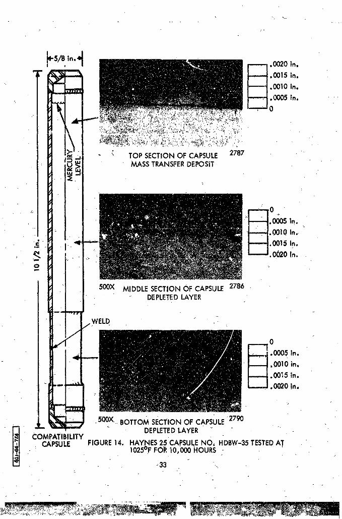
c. - Capsule No. HDBW-3_ 10_000 Hours at 1025°F
Examination of the microstructure along the
entire length of the capsule showed a typical depleted surface layer of
t£e tube,wall atthe bottom of the capsule, Amass transfer deposit was
found at the top of the capsule, Typical microstructures are shown
in 'Figure-14. The depleted layer was apprgximately 0,002 in. dleep. No
!:_ spalllng Of the-depleted layer was observed.G
"• r9
-. - o. "-" -L-> - .
%
2
2.
32L
1965012957-043
" 500X MIDDLESECTIONOF CAPSULE2786" DEPLETEDLAYER
WELD
_ 0-L.-.,-J.0005 in.
. , --i!___.t, 0010 in,
- I'_ "00_'5 in.• L.......J. 0020 in,
>
.500X.. BOTTOMSECTIONOF CAPSULE2790
COMPATIBILITY DEPLETEDLAYERCAPSULE FIGURE14. HAYNES25CApSUI_ENO, HDBW-35TESTED_AT
I025°F FOR10,000 HOURS '
....._,_ _.-_-,--'_,__ _'-._.:'._._.-_._-'_-_,_:_:,_mm-':':.....:_: "_ " "
] g650 ] 2957-044
I
...............
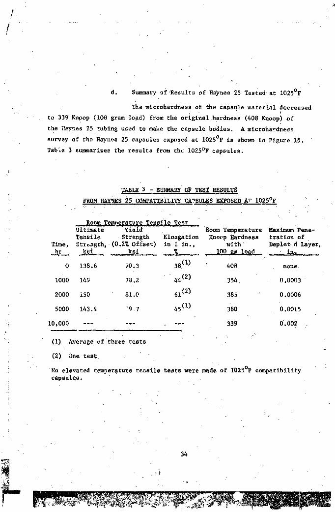
d. Summary ofResults of Haynes 25 Tested-at I025°F
The mlcrohardness of the capsule materEal decreased
to 339 Kn_op (I00 gram load) from the or_glnalhardness (408 Knoop) of
the i_ynes 25 tubing used to make the capsule bOdles. A microhardness
survey of the Haynes 25 capsules exposed at i025°F is shown in Figure 15.
Table 3 summarlzee the results from the IO25°F capsules.
3 -S ARyOFZEST sFROM.HAYNES 25 COMPATIBiLITY CAPSULES EXPOSED AT I025°F
Room Temperature Tens_l,e;TestUltimate Yield Room Temperature Maximum Pene-Tensile Strength Elongation Kno_,pHardness tration of
Time, Stz_ng=h, (0.2% Offset) in I in., with _ Deplet.d La#er,hr ks_ ksi _ I00 gm _oad in-.
. ° -.
0 138.6 70.3 38(1) 408 none.
I000 149 78.2 _4(2) 354. 0.0003 •
2000 150 81.0 61(2) 385 : 0.0006
5000 143.4 "q_7 45(1) 380 0.0015
._ i0,000 ....... _ --- 339 0_002
(1) Average of three tests
(2) One =est
: No elevated temperature tensile te_ts were made of I_025°Fcompatibility
capsules.

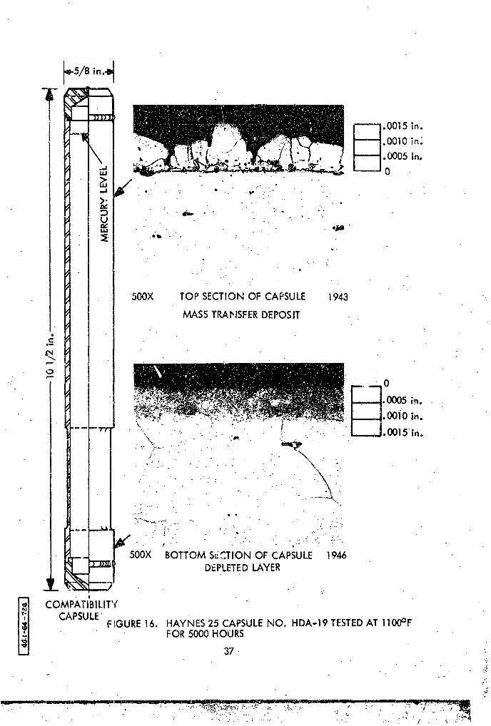
2. Capsules Exposed at ll00°F
a. Capsule No. HDA-19 - 5000 Hours at llO0°F
This capsule showed the same corr,Jsion pattern
found in the 5000 hour, I025CF capsule, l'he depleted layer was approximateiy
0_0013 in. deep and extended tc ti_emiddle of _he capsule. No evidence of
spalling of the depleted layer was found. The mass transfer deposit formed
near the top of the capsule built up to 0.0015 in. maximtun. Typical
sections of the top and bottom _or£ions of the capsule are shown in Figure 16.
36
t - 7.
t
1965012957-047

b. Capsule No. HDA-9 -I0,000 Hours at llO0°F
Corrosion effects were found along the entire length
of the capsule. A depleted layer was found along the bottom section of the
capsule approximately 0.002 in. deep, maximum. The depleted layer tapered
Off Lo a very thin layer, but it extended under the mass transfer deposit
found at the top of the capsule. No evidence of _palllng ofthe depleted
layer is evident. Typical _eetions are shown in Figure 17.
i
38
"L
1965012957-049


sr
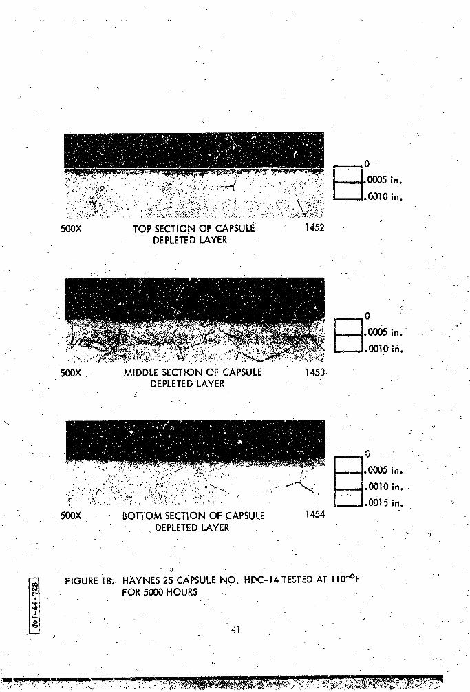
c. Capsule No. HDC-14 - 5000 Hours at llO0°F
This capsule and a similar 10,000 hour capsule
operated under nearly isothermal conditions_\-
A depleted layer varying from 0.00013 to.0.0003 in.
thick was found along the length of.the 5000 hour-.isothermal Capsule, "No
correlation between depth and position along the capsule was noted. The
elements leached fron the deplete¢ layer apparently precipitated in the Hg
and no mass transfer deposit was formed. - Photomicrographs of the Cop, middle,
and bottom sections of the capsule are shown in Figure 18.
.° -:
<_':
i
q_
] 9650] 2957-05]
.- . ..

d." Capsule No. HDC-II _ i0,000 Hour_ at ll00°F
A very thin depleted layer was found along the
entire length of tee capsule and a mass transfer deposit was evident near
the_top. Typical sections:of _he top and bottom of the capsule-are shown
in Figure 19. T'ni_ capsule Was a vacuum Lypecvp..psule .and itis believed
: that the mass transfer deposit resulted from retiuxlng in the space
above the-liquid,
: -. :i
-.- a; • . -. :
- .- : . :-2
! -
_ _- " 42
..... "- • -- -- '----- _ : _ _'_'..2.
1965012957-053

"i'll FIGURE 19. HAYNES 25_CAPSULENO. HDC-11 TESTEDAT ll00°FFOIl I0,000 HOURS
43
."'_'.i,; " "_,, ' .7 i ' ' , ""'if' . . . . .' . • . .,,Ir__ ...................................... _ ...... _.,.,.,...,,,,-til,i._,il=,.;,,. ,,,,,.=_ .,lilLt..
1g05017057-054

!
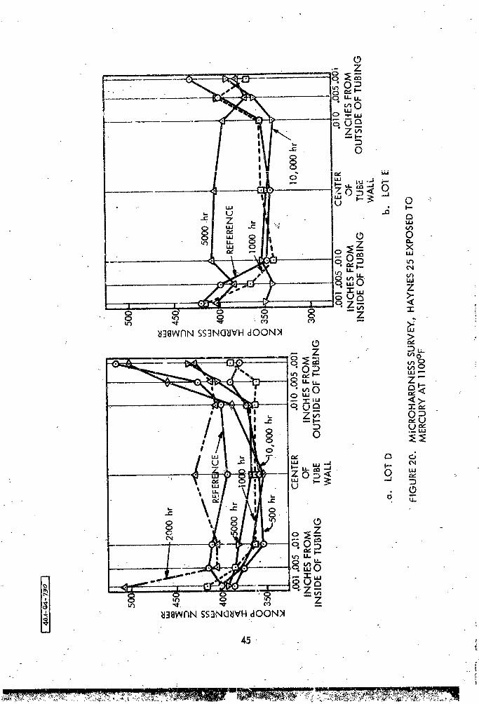
e. Sunmmry of Results of Haynes 25 Tested at llO0°F
A microhardness survey of the Haynes 25 capsules
exposed to I_ at ll00°F is shownin Figure 20, and results from these capsules
are .stmmmrized in Table 4. (The lot designations in Figure 20 indicate cap-
su_es-made from different ingots of Haynes 25, see Table 2).
TABLE4
SUMMARY OF TEST RESULTS FROM HAYNES-25 "- :
COMPATIBILI-TZ- CAPSULES EXPOSED AT ll00UF :
Room Te_e=hture Tensile Teet Tensile Test at ll00?P - _h_-Tem-gltimate -- Yield .: Ultimate Y£eld pez_ture, _laxianmPene-Tensile Strength Elon_ion Tensile "Strength Elonsat_on Knoop _ard- t_ation of De-
Time, St_en3th _ _0.2Z Offset) in 1 inch_ Streugt_, (0.2_ Offset) in I t_h_ nesu-w£_h plete_ Laye.,
0 138,6 70.'3 38 (1) Not Tested 408 None
500 154 -75 /+8 (2) Not Tested 374 None
I000 149 76 57 (3) Not Tested 378 0.9005
2000 131 83 20 (2) 83.3 63.3 24 (2) 400 0.0008
5000 136.2. 86 21 Test Not 393 0.0013• Planned .
10_000 Test Not Test Not 409 0.002
Co_leted Planned
(1) Average of three testa
(2) ODe tes_
(3) Ave_ase of two testa .
f
i
£
1965012957-055

i/
3. Capsule_EEx_posed at i175°F
a. C_psule No. EOB-30 - 2000 Hours at i175°F
This capsule showed the same pattern found _n the
?000 hour I025°F capsule, except that the depleted layer appareptly was
spalle_ in some places. Also, the depleted layer did not graduate into the
mass transfer deposit b_t continued along under t_e deposit for a distance
of about three %nches. The largest crystals were approximately 0.0015 in.
in maximum dfmenBion. T_plcal photomicrographs are shown in Figure 21.[
46
1965012957-057

= In.
500 286
• _-
J_.._.ooo5_,. -I IL_.._J.O010 |0.
.E I __'- 500X 1278
O MIDDLE SECTION OF CAPSULEDEPLETEDLAYER
;"____, ,,_ °ooo:_500X i277
BOTTOM SECTION OF CAPSULE
_"_I: DEPLETEDLAYERa
COMPATIBILITY
CAPSULE FIGURE21. HAYNES 25 CAPSULENO. HDB-30 TESTEDAT 11750FFOR 2000 HOURS
47
" - _-.'Z-" " _
- : _ i Iflr ..................... 111111 II I I I' < =" "_
1965012957-058
_,. Capsule No J_DBW-37 5000 Hours at I175°F
The _epleted layer found near the bottom of the
capsule had spa!!ed in several _reas (See Figure 22). The depleted !_yer
extended down in small V-shaped areas in what appeared to he intergranular
attack. The intergranular attack did not appeer to advance rapidly, however,
but stayed just ahead of the depleted layer. A depleted layer was found
along the entire length of the capsule, extending under the mass transfer deposit
at the top. Spalling of the depleted layer took place only in the bottom
of the capsule where the temperature was highest.
48
1965012957-059

BOTTOM SECTION OF CAPSULEAREAWHEREDEPLETEDLAYERHAS SPALLED
COMPATIBILITY
CAPSULE
FIGURE22. HAYNES 25 CAPSULENO. HDBW-37 TESTEDAT 1175°FFOR 5000 HOURS
49

c. Summary of Results of Haynes 25 Tested at I!75°F.
The resultf of microhardness surveys are shown in
Figure 23; test results are sunmmrized in Table 5.
TABLE 5
SUMMARY OF TEST RESULTS FROM HAYNES-25
COMPATIBILITY CAPSULES EXPOSED AT I175°F
Room Temperature Tensile Test Tensile Test at 1175°F Room Tem-Ulttamte Yield Ultimate YieLd perature Maximum Pent-
Tensile Strength Elongatlon Tehsile Strength Elongation Knoop Hard- tratlon of De-
Time_ Strength, (0.2Z Offset) in I inch, Strength, (0.2Z Offset) h, 1 inch, ness with pleted L_r,hr ksi ksi Z ksl ksi Z I00 _mLoad in. _--
0 138.6 70.3 38(1) Not Tested 408 None
500 Not Tested Not Tested 418 0_0001
I000 125 92 15(2) 86.3 57 7.0(2,4) 409 0.000_
2000 122 109 4 (2,3) 87.6 55.1 15(2,5) 445 0.0011
5000 Test Not Test Not 498 0.C015
Completed Pla_med
(I) Averase of three tests
(2) One test
(3) The tensile specimen used in this test had a butt weld across tllecenter of the reduced section.
._nebutt weld was made in the capsule bJdy and machined on both sides when the capsule was fabricated.
_) The tensile test failed in the grips. Values of units and elongation are low
(5) NO weld £_ the center of the reduced sectlou
(6) Depleted laye_ apparently did not form, or spalled off.
50
J
1965012957-061

OZ
-+... - o__ _ o_:_
"--_ "---_<,,:_ __-_-_-
-. ._0
". o__
..z_0
' 1 __ o oLU
_' _._/ o o
-, / I°;_ R°__ ,,,x
e'" , ,:,_.,.... , _ ,, , tqSo zo o o o o o o Z <_
_::]BWANSS:INa_VH dOON>l _._LU
>
u_ 0v-)l_
__ Z_
__ io ,,,o _:>-• "_.'_ I--u__. O_
P _7 T ioz_ _u
II ':/_ I_ _
..... __ I_o_,#/_,{',_f I o" _, '_, Z
----__--_-- IS £° i_ I---
; ', \'N !.., _,...... _)r',"_a_ .:.; 18,_o*SE_u
........ o.z__
o o _ 8 z
_I_WIqN SS::IN(]_IVHdOON>l
51
1965012957-062

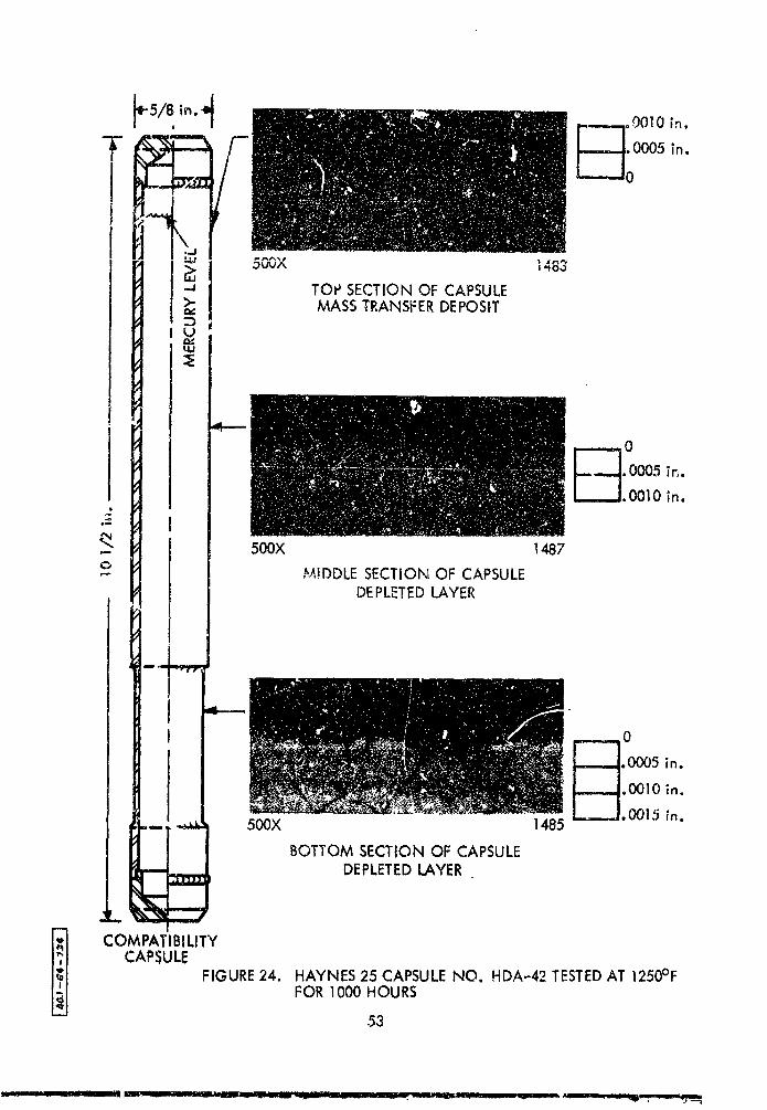
4. Capsules Exvosed at 1250°F
a. Capsule No. HDA-42- I000 Hours at 1250°F
The same pattern as in the I025°F, 2000 _kour
capsule was again found, however, almost complete _p_ll£_g of the depleted
layer appeared to have occurred. Amass transfer deposit was evident
over 2% square inches near the top of the capsule. The mass transfer deposit
appeared to be more dense than the deposits observed in the I025c and i175°F
,:apsules. The greatest thickness of the mass transfer layer was 0.0006 in.
Typical pnotomlcrographs &re shown in Figure 24,
52
i
1965012957-063
_00
•"_ TOP SECTION OF CAPSULE_" MASS TRANSFERDEPOSIT
U
0
. 0005 in..0010 in.
11
.- 500X 1487
- M!DDLE SECTION OF CAPSULEDEPLETEDLAYER
I.+,,-,f
L_-0
.0005 in.
_.0015 in._,_ 500X 1485
BOTTOM SECTION OF CAPSULEDEPLETEDLAYER
,,. ,.,./
COMPATIBILITY
CAPSULEFIGURE24. HAYNES 25 CAPSULENO. HDA-42 TESTEDAT 1250°F
FOR 1000 HOURS
53
1965012957-064

b. Capsule No.HDBW-46 2000 Hours at 1250°F
The depleted layer found along the length of the
capsule was thinner than in the capsules exposed at lower temperatures, again
in small V-shaped areas before the overall surface is attacked. Figure 25
shows a typical section of this corrosion pattern. The attack did not appear
to be entirely intergranular_ The mass transfer deposit was similar tn that
found in the capsules exposed at lowec temperatures except that it was more
dense and the depleted layer continued under the deposit.
54
1965012957-065

.0005 in,,
.O010 in.L_,,J. 0015 in.
E
o 500X 1>'24
MIDDLE SECTION OF CAPSULEDEPLETEDLAYER
__ _ /WELD/
./ 0
•" _. 0005 in.
,I_IO in.i----- 11.0015 in.
.-- 5_X 1_2_ _,P'n
BOTTOM SECTION OF CAPSULE
DEPLETEDLAYERL..I
COMPATIBILITY
CAPSUL_ F:GURE25. HAYNES 25 CAPSULENO. HDBW-46 TESTEDAT 1250°FFOR 2CX_OHOURS
55
1965012957-066

c. Summary of Results of Haynes 25 Tested at !250°F
Microhardness of the 1250°F capsules is presented
in Figure 26 and results are suxmmarized in Table 6.
TABLE 6
SUMMARY OF I_ST RESULTS FROM P_YNES-25
COMPATIBILITY CAPSULES EXPOSED AT 1250°F
Room Temper@ture Tensile Test Tensile Test at 1250°F Room Tem-Ultimate Yield Ultimate _leld perature Maximum Pens-
Tensile Strength Elongation Tensile Strength Elongation Knoop Hard- tratlon of De-
Time. Strength, (0.2_ Offset) in 1 inch, Strength, (0.2_ OffseL) in i inch, neas with pleted Layer,
,_hz_.,. ksi._, kai Z ksl ksl Z, i00___._ In,(6
0 138.6 70.3 38(1) Not Tested 408 None
500 Not Tested 91.] "62.1 12(3) 441 0.0002
1000 I18.6 109.3 _ (2,3) 91.4 71.9 6(3) 505 0.00035
?000 (A) 139 109.6 4.0 (3) 540 0.000;5
(g) 155 137.3 1.0 (3,4) 86.4 (2,4,5)
(1) Average of three teals
(2) The ten.ile test failed in the grips. No elongation could be measured and the ultimate tensilestrength ualue is low.
(3) One test
(4) Thls tensile specimen had a butt weld across the center of the reduced section. The butt weld wax
made Jn the capsule body and machined on both sides when the _apeule was fabricated. The tensilespecimen broke in the weld.
(5) The tensile specimen broke immediately a_ter the load was applied. The yield strength and elongationcould not be measured.
(6) Depleted layer apparently partially spalleo.
56
%t
1965012957-067

I i i .,kl
_: 500450
o _ .400 :
o00i .005 .010 CENTEROF .010.005 .001
INCHES FROM TUBEWAL_L INCHES FROM': iSIDE OF TUBING OUTSIDE OF TUBING
FIGURE26. MICROHARDNESSSURVEY, HAYNES 25 LO'_ DEXPOSEDTO MERCURYAT 1250°F
57
.................. . ,e'mlmmm'_ . _ _..;. _. I.L.L_ J_..v- _'.'u,-._._ I
1965012957-068

5_ Corrosion Product Analypls
T_.e cccrosion products which were generated in the i025°F
2000 hr, li00°F 5000 hr, i175°F 2000 hr, 1250°F i000 hr, and 1250°F 2000 hr
capsules and _ere not attached to the walls were recovered from the mercury.,-
This was done by distilling the mercury at a very slow rate and low temperature
(about 200°F) to prevent car_'uver as very fine particles. Analysis of the powder
_'X-ray diffraction indicated that the main corrosion product from all of
these capsules was cobaI£, but _ickel, chromium, and iron were present in lesser
amounts. Nolndication of tungsten wos found in any of _he corrosio_ products
from the capsules tested. X-ray diffraction showed only C_-Co. It appears that
cobalt uucieates and grows in the liquid phase, but only to very small particles,
_hile nSckel and chromlumnucleate on a surface and prow into large crystals.
6. Mechanical Properties Tests
Room temperature tensile tests made on tensile specimens
(Figure 9) cut from Haynes 25 compatlbilI_ I capsules (T_bles 4 through 6) sh_ed
loss of room temperature tensile ductility in t_aynes 25 after exposure to Hg
at llO0°F, I175°F, and 1250°F for times up to 2000 hours. It was therefore
decided to run elevated temperature tensile tests on specimens cut from the
exposed Haynes 25 compatibility capsules. _ improvement ll_ductility would
be expe6ted at the higher temperatures, as compared to the room temperatu_#e
ductility.
Elevated temperature tensile tests were completed On Haynes
25 specimens as listed in T_ _s 4 through6 . The test temperature for each
capsule was the same a_ the exposure temperature during the compatlbility
test, to avoid further age hardening of the Haynes 25. No elevated temperature
|.ests were made on the Haynes 25 competlbility capsules exposed at I025°F because
the room temperature tests indicated no loss of ductility when compared to the
unexposed Haynes 25.
B. TYPE 405 STAI.NLESS _TEEL
1. C._psules Expo_._d at I025°F
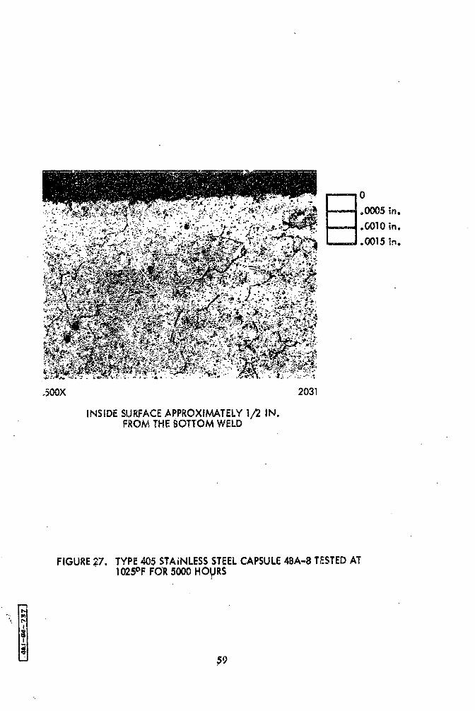
a_ Capsule No.4BA-8 - 5000 Hours at I025°F "
No corrosion labor of any type was found on the Type 405
stainless steel capsule exposed for 5000 hours at I025°F. A mass transfer deposit
was formed at the top of the capsule, indicating that an even solution attack
must have taken place. Figure 27 shows a =ypica! m_crostruct,re of the inside
of the capsule.
58
1965012957-069
.-:-...;-.,,
.500X 2031
INSIDE SURFACEAPPROXIMATELY1/'2 IN.FROM THE BOTTOM WELD
FIGURE27. TYPE405STAINLESSSTEELCAPSULE4BA-8T_STEDAT_025°FFaR5OO0HOURS
"':,_.
_9
1965012957-070

b. Capsule No. 4BB-13 - I0,000 Hours at i025°F
The microstructures'of typical sections of the inside
surface of this capsule are sh_w_ in Figure 28. A s!ig_t mass transfer deposit
: was formed at th_ top, or coolest, part of the cap_u!e, but it was much l_ss
than that'.formed in the 10,000 hour, I025°F Haynes 25 capsule. No depleted
layer was formed onthe bottom qeetion of the capsule, indicating that solution
attack of the entire wall had takee place rather than selective leaching of
individual constituents.
60
1965012957-071

1965012957-072

2. Capsules Exposed at ll00°F
a. Type 405 Stainless Steel Capsule No. 4BA-45000 Hours at ll00°F
No corrosion layer was found. A slight rougheningk
of the surface occurred 5ut no intergranular penetration occ_red. Figure 29
s._ws a typical microstructure from the capsule ezposea fo_ 5000 hours
at ii00°F.
62
1965012957-073

FIGURE29. TYPE405 STAINLESSSTEELCAPSULENO. 4BA-4 TESTEDAT 1100°F FOR 5000 FLOURS
!
...|I
.!
63
1965012957-074
b. Caspule No.4BA-I - i0,000 Hours at ll00°F
No depleted layer was found on the inside surface.
Solution attack appeared to have taken place along the entire length of the
capsule. No mass transfer deposit, such as that found in the 405 stainless
steel capsule exposed at 1025QF, was found in the top sectien of the llO0°F
capsule. A mlcrostructure from the bottom of the capsule is shown in Figure 30.
Corrosion products were found in the Hg. Apparently
these corrosion products precipitated in the Hg instead of nucleating on the
wall and growing as crystals. The difference in the behavior of the
corrosion products formed in the 1025° and ll00°F capsules may be due to
the temperatures in the top portions of the capsules. The top sections of
the 1025°F capsuiesoperated at approximately 850°F, while those in the llOOCF
capsules operated at about 960°F.
64
1965012957-075

5/8, In. 41
-rMERCURY
LEVEL
0
.0005 in.
._.,J,, 0010 in.-===-L.C_|5 in.
,-..-J, 0020 in.
=.,.,..
COMPATIBILITYCAPSULE FIGURE30. TYPE 405 STAINLESSSTEELCAPSULENO. 4BA..,1TESTED
AT II_F FQR 10,000 HOURS
65
1965012957-076
c. Capsule No.4BA-63 - 2000 Hours at ll00°F with
Columbium Strip
This capsule contained a columbium strip inside the
capsule to test for bimetallic effects _lhen Cb and Type 405 stainless steel
are exposed to Hg. Figure 31 shows the position of the columbium strip in
the capsule and typical microstructures of the strip and the capsule wall.
Mass transfer deposits were found on the top sections
of the columbium strip and the capsule. The mass 'transfer deposits were similar
to those fou,d In the ot_.er llO0OF type 405 stainless steel capsules without
a columblum strip.
The samples of the columblum strip were metallographlcally
color stained to reveal any reaction with the mass transfer deposits or
corrosion at the bottom seetion of the columblum strip. No indications of
corrosion or reaction of the Cb with th_ mass transfer deposits were observed.
Microhardness measurements on _he top and bottom of
the columbium strip after exposure indicated that there was no change in hardness.
56
1965012957-077

__ .0015 in.
_" 5/8 in. 4 ,0010 in.
F_ .0005 in.
0
'," " ' ' ' ' ', ' "' ' " ' , . "' ""i " '
d500X 2800
TOP SECTION OF COLUMBIUM STRIPMASSTRANSFERDEPOS!T
I
J _L llll, _.'/ . t, _ , ; 7-
-" ,- " _ .0005 in.
I "..; ::.... .0010 inL___1.0015 !n.
.__
H�o _ 500× 280!
W SECTION OFBOTTOM
,COLUMBI_UM,STRIP
, F_].ooo,,o.',: _': -; ;.-'._":_'.._.'111
I I ;.,_'./=.,:'_.":_.".--_.:._._:'..*-_"t_I I _'_ • .s, . ., . • ; "--"
I
! 500X 2796
BOTTOM SECTION OF CAPSULE
I
1 FIGURE31. TYPE405 STAINLESSSTEEl.CAPSULENO. 4BA-63-_ WITH COLUMBIUM STRIPTESTEDAT 1100°F FOR
COMPATIBILITY 2000 HOURSCAPSULE
67
1965012957-078

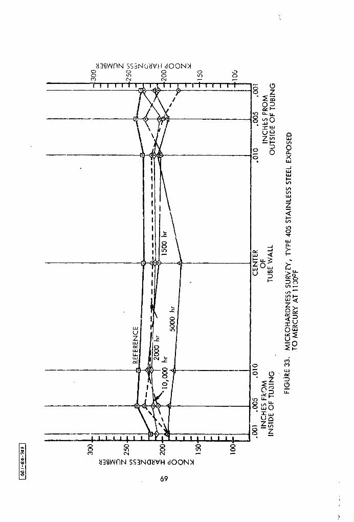
d. Summary of Mi_rohardness Tests
A sunmmry of microhardnesses is shown in Figures 32
and 33. The capsules with Cb strips are not included.
100
.001 .005 .0i 0 CENTEI_ .010 .005 °00-1INCHES FROM OF INCHiZS FROM
INSIDE OF TU_!NG TUB_ OUTSIDE C_,c TUBINGWALL
FIGURE32. MICROHARDNESS SURVEY, TYPE.40:5 %.,_'4LESS STEELEXPOSEDTO MERCURYAT IO25°F
68
.:
1965012957-079
1965012957-080

C. AM-350 (,3A_ NO_ AAA°50 AND .A._-51 - 500 HOURSAr 1250°FI
One capsule of AM-350 was .tested in the solution annealed
condition (1875°F followed by a water quench) and a second capsule was
tested in the equalized condition (solution anneal plus 1425°F for 3 hours
followed by air cooling and i025°F foz 3 hours followed by a%r-coollng). A
very small amount of mass transfer deposit for,red _z: the c.#olest (top) end
of each capsule. As illustrated in Fi-gure 34, the bottom portion of the
equalized AM_350 capsule was attacked to a greater degree than was the
solution annealed AM-350 capsule.
Equalized AM-350 stalnless steel therefore appeared to be less
resistant to mercury corrosion than the solution ennealed AM-350 after
exposure for 500 hours at 1250°F. _"Analysis of the lO00-hour and 2000-hour
capsules of equalized and solution annealed AM-350-must be completed before
any firm conclusion can be reached concerning the suitability of this alloy.
Other invest_Bators have reported that equalized AM-350 was more resistant
to Hg than solution annealed AM-350 under .ref!uxing conditions.
70
1965012957-081

500X SOLUTION ANNEALEDINSIDE SURFACEAT BOTTOM OF CAPSULE
::::::_:j0°0005in.d
_ o0010in,.0015 in,
..._ o0020 in.
500X 5QUAL!ZED 2635INSIDE SURFACEAT BOTTOM OF CAPSULE
!
= FIGURE 34. AM-350 CAPSULESTESTEDAT 1250°F FOR 500 HOURS -.
71 _.
] 9650 ] 2957-082

!i
D. 9% CHROMIUM - 1% MOI,YBDENUM ALLOY (CAPSUL_ NO. 9AA-71
LT_I COLUMBIUM STRIP 500 HOURS at 1250°F_
Figure 35 shoWs the position of the cclumhium _trip in the
cap_ui_s aud .......................ui_ m_ULO_LL,_u_=_ v__ the capsule wall and the co!umbium
strip. Mass transfer deposits were found in the top portion of the capsule
both on the columbium strip and the wall of the capsule. No depleted layer
was found mt the bottom of the capsule. Th,z lack of a depletion layer plus
the presence of the mass transfer depos.its indicate that an even sc]ution
type attack must have taken place. This is typical of the type of attack
found in the .Type 405 stainless steel compatibility capsules.
There was no reaction between the mass transfer deposits
(assumed to be Cr) and the Cb, judging from the microstructure of the latter.
o *This was after an exposure of 500 hours at between II00 and 1150 F.
•"ne mic:oohardness of the columbium strip increased after
exposure. The microhardness of the top section of the strip was 145 Knoop
(I00 gram load) amd that of the bottom section was 139 Knoop. The original
hardness of the "-'olumbium strip was 130 Knoop.
*Top of this 12500F capsule operated at a temperature I00 to 150°F lower than
that of the bottom.
72
1965012957-083

1965012957-084

E. COLUMBIUM - 1% ZIRCONIUM ALLOY
Two Cb-iZr capsules were tested. One capsule was exposed for 4300
hours at U00°F and the other capsule was exposed for 2500 hours at I175°F.
The capsule in the i175°F furnace developed a leak in a closure weld
between the 2000 and 2500 hour period, driving all the Hg from the capsule.
Both columbium capsules were sectioned for metal!ographic and
micro-_v=mination of the inside surface of the tubing. The metallographic
samples indicated that the Hg had not attacked th& inside _urface of either
capsule. Micro-examination of the inside surfaces of the capsules revealed
no mass transfer deposit at the top of the capsules or any form of attack by
the Hg. The mercury removed from the 4300 hour, ll00°F capsule was bright and
clean with no evidence of the precipitates or powders found in the Haynes 25
and Type 405 stainless steel compatibility capsLles exposed at similar
temperatures (Figure 36).
Hicrohardness readings (Knoop, I00 gram load) were made on a
ring cut from the bottom of each Cb-iZr capsule and an unexposed section
of the same lot of tubing. The average hardness of the ii75°F capsule (182
Knoop) and the ll00°F capsule (189 Knoop) was less than that of the unexposed
tubing (228 Knoop). Stress relief of the tubing probably accounts for the8
reduction in hardness of the Cb-iZr material.
74
1965012957-085
1965012957-086
V. DISCUSSION OF HAYNES 25 CORROSION TESTS
A. CORRO_,ION
The results of the capsule tests to determine the corrosion effects
of Hg on Haynes 25 are surmaarized below. Some solution of the _apsule wall
in the liquid phase hot zone, subsequent mass transfer and deposition of
mass transfer products in the cold zone was noted in all Haynes 25 capsules
at all test temperatures, except in the isothermal capsules, where little
corrosion was evident. Analysis of results showed that the ce_tituents
involved in the mass transfer effects are Ni, Cr, and Co_ although
not necessarily in that quantitative order. The thickness of depletion
layers varied from 0.0005 in. in the i025°F, 2000-hour capsule test to
roughly 0.0020 in. in the ll00°F, 10,O00-hour capsule and the i025°F, lO,000-
hour capsule. Mass transfer deposits ranged from 0.0005 to 0.0015 in. in
thickness.
From the patterns found after sectioning some capsules along
their lengths, it is evident that measurement of the depth of the depleted
layer near the bottom of the capsule can be misleading when Judging the amount
of attack, especially in those capsules exposed at the higher temperatures.
_e corrosion pattern found in the capsules evaluated thus far indicates that
the depleted layer is removed or spalls at the higher exposure tempecatures
(I175 ° and 1250PF). The thin depleted layers found on the 1250°F compatibility
76
1965012957-087

capsules and the evidence of spalling found on the i175°F, 2000 hour capsule
lead to this conclusion. _erefore, the penetration figures reported for
the higher-temperature capsules are believed to be low, since they do not
include the spalled material.
No evidence of stress corrosion by Hg was found in any of the
Haynes 25 capsules with a reduced wall thickness in the are_ _ear the bottem
of the capsule. The stress in the reduced wall varied up to 8000 psi.
The isothermal capsules (llO0°F, 5000 and i0,000 hours) illustrate
the relatively small amount of corrosion and mass transfer that takes place
when there is little or no AT in the system. When the Hg becomes saturated
with solute, no mechanism remains for further corrosion. Actually, because
of a small _T (< lO°F) from the bottom to the top of the heating block
a slight circulation and mass transfer potential probably existed. In the
regular compatibility capsules, the mercury circulates slowly due to a
_ T of about 150°F along the capsule length, creating a much larger mass
transfer potential.
B. MECHANICAL PROPERTIES
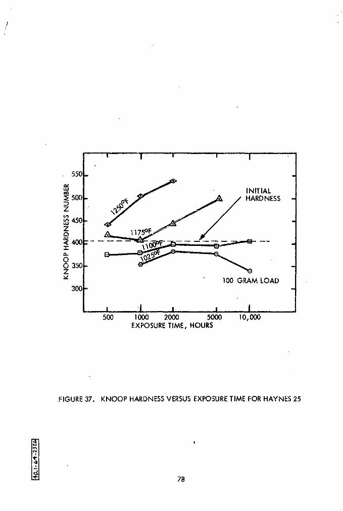
The Haynes 25 capsules exposed to test temperatures in the
range from 1175 ° to 1250°F exhibited considerable age hardening, as shown
in Figure 37. T_s degree of age hardening could be detrimental if Haynes 25
were used as the containment material for Hg in the SNAP-8 system. The effect
of age hardening on cther mechanical properties of Haynes 25, such as impact
strength and notch sensitivity, was not determined.
The values obtained from the tensile tests indicate that the
mechanical properties of Haynes 25 are affected by age hardening. However,
the tensile values are not the same as typical or minimum values obtained for
Haynes 25 aged in air at the test temperature. It should be remembered that
the tensile specimens machined from compatibility capsules are not standard
test specimens and that they have been exposed to Hg; therefore, the values
can only be compared with results from tensile tests conducted with the same
type of specimans exposed to similar environments.
77
1965012957-088
' " I ' ' ' I
550.
.v
u_ • INITIALa_
:_ 500 - HARDNESS =
Z
v_45014./
ZQ
400 ---_,__- 7_- --= -
:350Z
v I00 GRAM LOAD300 =
! 1 .... , , I500 1000 2000 5000 1O, gO0
EXPOSURETIME, HOURS
FIGURE37. KNOOP HARDNESSVERSUSEXPOSURETIME FOR HAYNES 25
78
1965012957-089
As would be expected, the ductility of Haynes 25 decreases as
the hardness increases. Figure 38 is a plot of tensile elongation versus
hardness for the compatibility specimens tested. There appears to be
poor correlation between tensile elongation and hardness around 400 Knoop;
_owever, the increasing hardness of the Haynes 2J exposed to temperatures of
I175°F and higher is a good indication of loss of room temperature ductility.
Age hardening of this alloy_ as evidenced in hardness increases and decreases
in ductility, does not occur below llO0°F.
79
1965012957-090

!
\ I J
--' _ - __=,,, • L,
50 "_ •
¥/,_ ._
0
,
_- 20 i '_%........
0 '_300 350 0
KNOOP HARDNESSNUMBERS, (100 GRAM LOAD)
FIGURE38. TENSILE ELONGATION VERSUSKNOOP HARDNESSFORHAYNES 25 TENSILETESTSPECIMENS
• ' 80
1965012957-091

Vl. MECHANICAL PROPERTIES OF AM-350
AM-350 alley in the solution annealed condition was selected as a c=_,dldate
material for containing Hg in the SNAP-8 system. Tensile and stress rupture data
were not available for AM-350 in the solution annealed condition at the
maximum temperature of the SNAP-8 system (!300°F). Solution annealed AM-350
sheet tensile _pecimens were placed in the compatibility furn.,ces and exposed
to vacuum for periods up to 2000 hours at 1025 °, ii00 °, 1175 °, and 1250°F.
The tensile test speclmemoriginally were to be rested at room tempera-
ture after exposure in the compatibility furnaces to determine the effect of
long-time exposure on the tensile properties of solution annealed AM-350.
After the first set of tensile specimens exposed for I000 hours at 1250°F were
tensile tested, it was decided to perform stress rupture tests on the balance
of the exposed specimens. The stress rupture tests would give more useful
in£ormation on the effects which long-time exposure would have on the
mechanical properties of AM-350.
Some tests are being run with equalized AM-350. The equalized condition
(1425OF for 3 hours followed by air cool: I025°F for 3 bouts followed by air
cool) is an overaging heat treatment used to improve the machlnability of AM-350.
The Hg eorrosinn resistance of AM-350 is improved when the material _ in the
equalized condition. The stability of the material at 1300°F may also be im-
proved after it is subjected to the overaging heat treatment.
*Concluded from other programs. See Section IV.C.
81
1965012957-092

i .!
e. .
The results of stress rupture tests (Table 7).completed during
the reporting period are plotted in Figure 39. Extrapolation of these
test results indicate that solution annealed ¢_M-350 should have a stress
rupture strength of 7000 psl for I000 hours and 4500 psi for IO,000 hours
at 1300°F.
TABLE 7 - SOLUTION ANNEALED AM-350 RUPTLq_E TESTS AT 1300°F
Pre-Te_t Exposure _.
Time, T_peratur_, Stress, Time to Rupture, Elongation in I in.
hr _ OF psi hr _ after rupture 7o
Unexposed 15,000 60 l:2
" i0,000 543 36
" lO_00O 580 35
" 8,000 1359 38
" 8,000 1447 !I (I)
" 8,000 1464 II (I)
2000 ii00 ._ 20,000 3.4 36
"" 2000 II00 15,000 14_3 36
2000 ii00 I0,000 126.0 20
2000 1025 i0,000 i0! 27
2000 1025 8,000 485 27
2000 1025 8,000 540 2i
2960 1175 8,000 216 46
2960 1175 6,000 892 21
EQUALIZED AH-350 (2) 15,000 182 56
15,000 137 55
i0,000 _ 2076 45
..._-.-':-:_'::- I0,000 (Test not complet_d a_ end of. repot.ring perJod)
_-... -..:- . 8_000 (Test not completed at end of reporting period)
'-::,._ ::: :_i ,.-:=- _..--.. (!) . _.-.sle-e_rl_'_, power failed after 1400 hours of the test. The specimen
.S..:...... -eOoled .to r_o_ temperature before the test was restarted.'_>:-,-.. .
--..'::.,- (2} '"1425°Y'}fo_ _ _ours, air cool, then 1025°F for 3 hours, air co01,
^ ..
5_-- .j : : .'" ,"" "7 _ "
.... ..... ,-_ :'-."_-:- --' .... . 82i -'-'.:--_ .," "'_..... ,"., -'_
" 'i.-_ .." "':
"19650 ] 2957-093

_-. _7,L..T-.C..... _L ..... ,, J]llll _,,] - ,,. , -- .... " .
1965012957-094

!
REFERENCES
I. M.F. Parkman and D. K. Whaley, Solubillty. of Irog_ Chromiumj
Nickel , Cobalt_ and Vanadium in Mercur7 and Concentrations of Those
Elements Found in Mercury after Contact with Iron_ Cobalt_ and
Vanadlum-Base Alloys, Aerojet-General Nucleonics Report No. AN-957
(1963).
2. L.T. Clark and M. F. Parkman, Effects of Wetting on Mercury Pool
Bo_lin 8 Heat Transfer , AeroJet-GeneraI Nucleonics Report No. AN-784
(December, 1962),
3. L.T. Clark, A Summmry of Literature on Relation Between Wetting
and Boiling Mercury Heat Transfer, Aerojet-General Nucleonics
Report No. AN-766..November, 1962.
4. Liquid M_tal Handbook, NA_?EXOS P-733(Rev)1952.
5. SNAP 1 and SNAP2 Reports.
6. J.P. Hartnett, W. E. Welch, Jr., and F. W. Larsen, "Free-Convectlon
Heat Transfer to Water and Mercury in an Enclosed Cylindrical Tube,"
in Nuclear Eng!neerlng- Part Vl, Chemical Engineering Progress
SymposlumSerles Volume 55, Number 23, A!ChE (1959).
l
7. W.E. Dunn, C. F. Bonilla, C.Ferstenbecg, and B. Gross, "Mass Transfer
in Liquid Metals,!' AIChE Journal 2:184 (1956).
8. Columblum Metallur_, Ed. by D. L. Douglass and F. W. Kur _, Interscience
Publishers, Inc., 1961, p. 414, Table I.
84
1965012957-095
Recommended


![[PPT]NGN Management Specifications - Internet · Web viewAnnex 2 to NGN Management Specification Roadmap NGN Management Specifications Annex 2 to NGNMFG-OD-013-R2, NGN](https://img.pdfslide.us/doc/110x75/5aa1f8287f8b9a1f6d8c9bec/pptngn-management-specifications-internet-viewannex-2-to-ngn-management.jpg)