,. .;,!¥
.<
Prepared by:
GSFC-410-ACE-012 December 15, 1993
NASA Goddard Space Flight Center ADVANCED COMPOSITION EXPLORER (ACE) PROJECT DATA MANAGEMENT PLAN (POMP)
Dr. Eric R. Christian Assistant to the Project Scientist
--------------------------------------------------------------------------------------ACE Project Data Management Plan

,.t
· -
Table of Contents
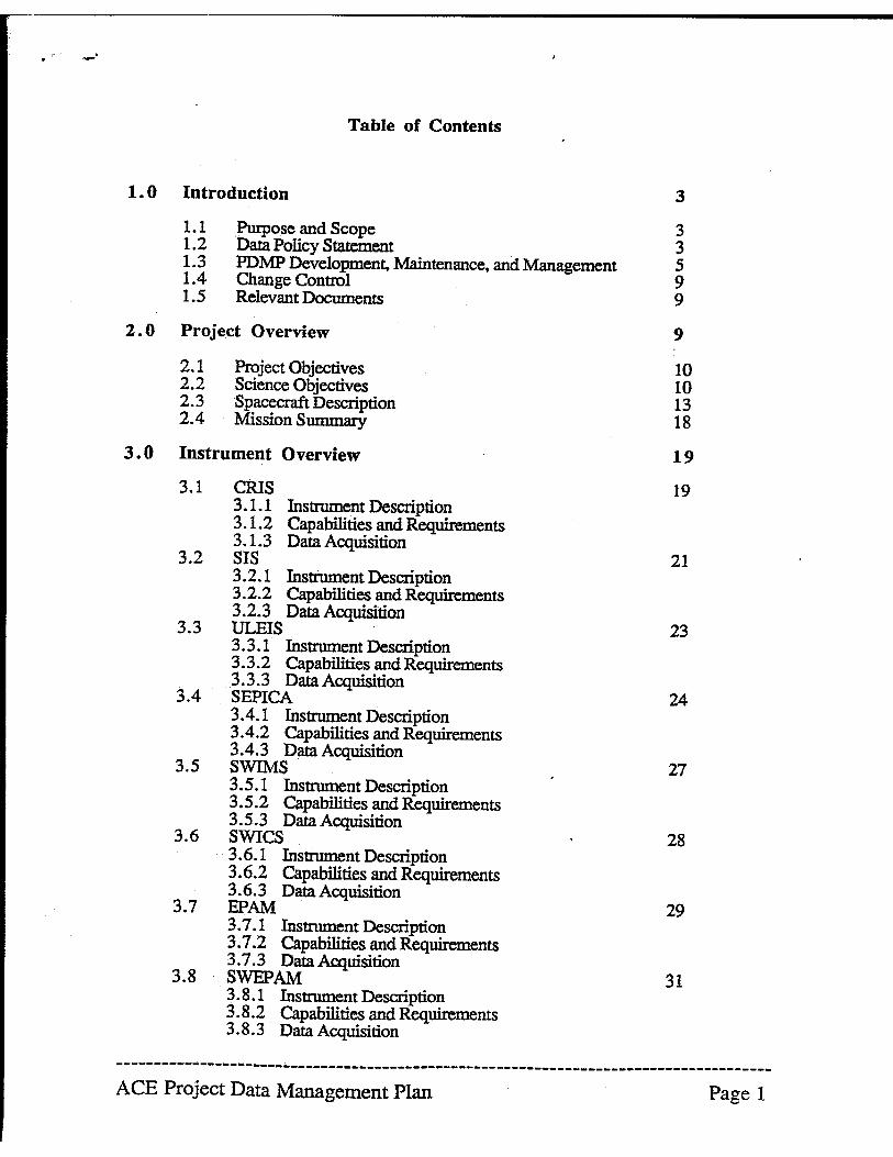
1.0 Introduction 3
1.1 Purpose and Scope 3 1.2 Data Policy Statement 3 1.3 POMP Development, Maintenance, and Management 5 1.4 Change Control 9 1.5 Relevant Documents 9
2.0 Project Overview 9
2.1 Project Objectives 10 2.2 Science Objectives 10 2.3 Spacecraft Description 13 2.4 Mission Summary 18
3.0 Instrument Overview 19
3.1 CRIS 19 3.1.1 Instrument Description 3.1.2 Capabilities and Requirements 3.1.3 Data Acquisition
3.2 SIS 21 3.2.1 Instrument Description 3.2.2 Capabilities and Requirements 3.2.3 Data Acquisition
3.3 ULEIS 23 3.3.1 Instrument Description 3.3.2 Capabilities and Requirements 3.3.3 Data Acquisition
24 3.4 SEPlCA 3.4.1 Instrument Description 3.4.2 Capabilities and Requirements 3.4.3 Data Acquisition
3.5 SWIMS 27 3.5.1 Instrument Description 3.5.2 Capabilities and Requirements 3.5.3 Data Acquisition
3.6 SWICS 28 3.6.1 Instrument Description 3.6.2 Capabilities and Requirements 3.6.3 Data Acquisition
3.7 EPAM 29 3.7.1 Instrument Description 3.7.2 Capabilities and Requirements 3.7.3 Data Acquisition
31 3.8 SWEPAM 3.8.1 Instrument Description 3.8.2 Capabilities and Requirements 3.8.3 Data Acquisition
--------------------------------------------------------------------------------------ACE Project Data Management Plan Page 1
3~9 MAG 3.9.1 Instrument Description 3.9.2 Capabilities and Requirements 3.9.3 Data Acquisition
4. 0 Project Data Flow
4.1
4.2
4.3
Mission Operations 4.1.1 Telemetry Services
4.1.1.1 Space to Ground Communication 4.1.1.2 Telemetry Processing
4.1.2 Mission Control 4.1.3 Mission Planning & Scheduling Science Operations 4.2.1 Science Control 4.2.2 Science Planning and Scheduling Continued Accessibility 4.3.1 Data Repositories
4.3.1.1 Project Data Repositories 4.3.1.2 Discipline Archives 4.3.1.3 NSSDC
4.3.2 Directories and Catalogs 4.3.3 Standards 4.3.4 Scientific Computing Resources 4.3.5 Networking Requirements
5.0 Products
5.1 Science Data Product Summary
6.0 Special Considerations
Glossary
Acronyms
References
Appendix A: Project Summary Tables
32
33
37
41
44
48
48
48
49
51
54
55
--------------------------------------------------------------------------------------ACE Project Data Management Plan Page 2
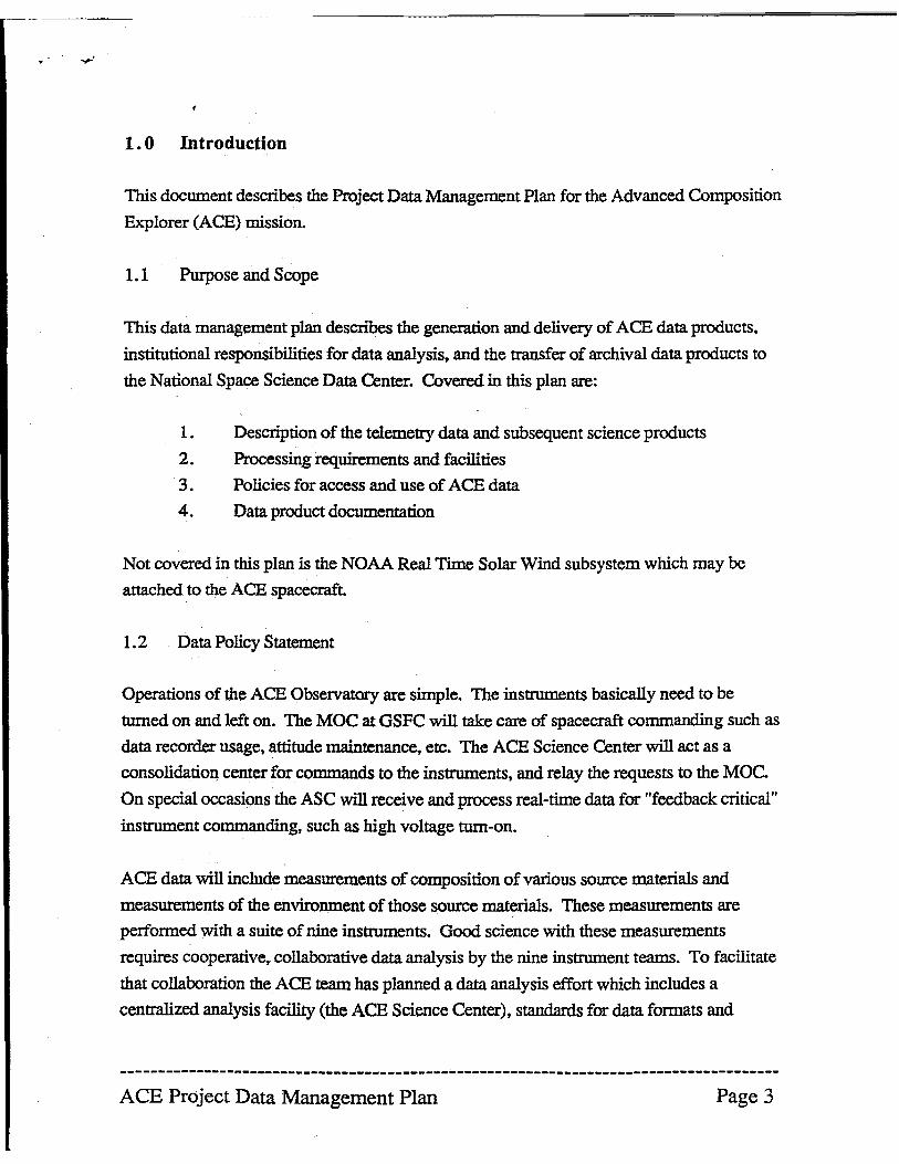
.. 1.0 Introduction
This document describes the Project Data Management Plan for the Advanced Composition
Explorer (ACE) mission.
1.1 Purpose and Scope
This data management plan describes the generation and delivery of ACE data products,
institutional responsibilities for data analysis, and the transfer of archival data products to
the National Space Science Data Center. Covered in this plan are:
1. Description of the telemetry data and subsequent science products
2. Processing requirements and facilities
3. Policies for access and use of ACE data
4. Data product documentation
Not covered in this plan is the NOAA Real Time Solar Wind subsystem which may be
attached to the ACE spacecraft.
1.2 Data Policy Statement
Operations of the ACE Observatory are simple. The instruments basically need to be
turned on and left on. The MOC at GSFC will take care of spacecraft commanding such as
data recorder usage, attitude maintenance, etc. The ACE Science Center will act as a
consolidation center for commands to the instruments, and relay the requests to the MOe.
On special occasions the ASC will receive and process real-time data for "feedback critical"
instrument commanding. such as high voltage tum-on.
ACE data will include measurements of composition of various source materials and
measurements of the environment of those source materials. These measurements are
perfonned with a suite of nine instruments. Good science with these measurements
requires cooperative, collaborative data analysis by the nine instrument teams. To facilitate
that collaboration the ACE team has planned a data analysis effort which includes a
centralized analysis facility (the ACE Science Center), standards for data formats and
--------------------------------------------------------------------------------------ACE Project Data Management Plan Page 3
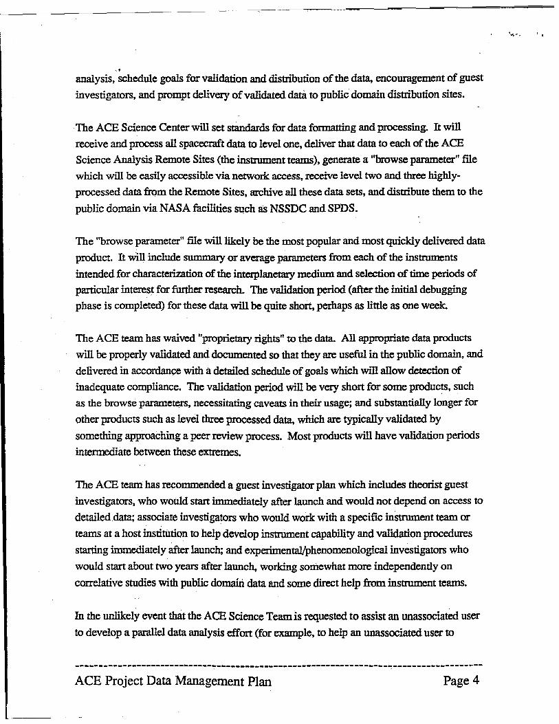
,. analysis, schedule goals for validation and distribution of the data, encouragement of guest
investigators, and prompt delivery of validated datil to public domain distribution sites.
The ACE Science Center will set standards for data formatting and processing. It will
receive and process all spacecraft data to level one, deliver that data to each of the ACE
Science Analysis Remote Sites (the instrument teams), generate a "browse parameter" file
which will be easily accessible via network access, receive level two and three highly
processed data from the Remote Sites, archive all these data sets, and distribute them to the
public domain via NASA facilities such as NSSDC and SPDS.
The "browse parameter" file will likely be the most popular and most quickly delivered data
product. It will include summary or average parameters from each of the instruments
intended for characterization of the interplanetary medium and selection of time periods of
particular interest for further research. The validation period (after the initial debugging
phase is completed) for these data will be quite short, perhaps as little as one week.
The ACE team has waived "proprietary rights" to the data. All appropriate data products
will be properly validated and documented so that they are useful in the public domain, and
delivered in accordance with a detailed schedule of goals which will allow detection of
inadequate compliance. The validation period will be very short for some produc~, such
as the browse parameters, necessitating caveats in their usage; and substantially longer for
other products such as level three processed data, which are typically validated by
something approaching a peer review process. Most products will have validation periods
intennediate between these extremes.
The ACE team has recommended a guest investigator plan which includes theorist guest
investigators, who would start immediately after launch and would not depend on access to
detailed data; associate investigators who would work with a specific instrument team or
teams at a host institution to help develop instrument capability and validation procedures
starting immediately after launch; and experimental/phenomenological investigators who
would start about two years after launch, working somewhat more independently on
correlative studies with public domaiIi data and some direct help from instrument teams.
In the unlikely event that the ACE Science Team is requested to assist an unassociated user
to develop a parallel data analysis effort (for example, to help an unassociated user to
------------------------------------------------------------------~-------------------
ACE Project Data Management Plan Page 4
.....
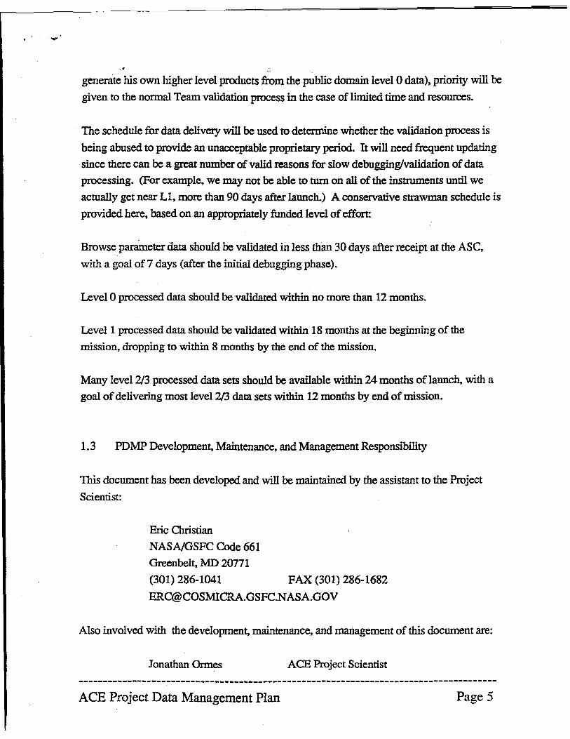
.. generate his own higher level products from the public domain level 0 data), priority will be
given to the normal Team validation process in the case of limited time and resources.
The schedule for data delivery will be used to determine whether the validation process is
being abused to provide an unacceptable proprietary pericxl. It will need frequent updating
since there can be a great number of valid reasons for slow debugging/validation of data
processing. (For example, we may not be able to tum on all of the instruments until we
actually get near Ll, more than 90 days after launch.) A conservative strawman schedule is
provided here, based on an appropriately funded level of effort:
Browse parameter data should be validated in less than 30 days after receipt at the ASC,
with a goal of7 days (after the initial debugging phase).
Level 0 processed data should be validated within no more than 12 months.
Level 1 processed data should be validated within 18 months at the beginning of the
mission, dropping to within 8 months by the end of the mission.
Many level 2/3 processed data sets should be available within 24 months of launch, with a
goal of delivering most level 2/3 data sets within 12 months by end of mission.
1.3 PDMP Development, Maintenance, and Management Responsibility
This document has been developed and will be maintained by the assistant to the Project
Scientist:
Eric Christian
NASNGSFC Code 661
Greenbelt, MD 20771
(301) 286-1041 FAX (301) 286-1682
Also involved with the development, maintenance, and management of this document are:
Jonathan Ormes ACE Project Scientist
--------------------------------------------------------------------------------------ACE Project Data Management Plan Page 5
NASNGSFC Code 660, Greenbelt. MD 20771
ACE Project Office
NASNQSFC Code 410, Greenbelt. MD 20771
Donald L. Margolies
Frank: Snow
Associate Project Manager for ACE
ACE Mission Operations Manager
California Institute of Technology
Space Radiation Laboratory Mail Code 220-47
Allan Frandsen 'Payload Manager
Thomas L. Garrard ACE Science Center Manager
The list of scientific Co-Investigarors and their affiliations are given below. The
Experiment Manager has also been identified for all nine instruments and the science center.
B.e. Stone Principal Investigator
California Institute of Technology
Space Radiation Laboratory Mail Code 220-47
Pasadena, CA 91125 USA
*W.R. Binns
Washington University
Dept. of Physics
St Louis, MO 63130 USA
*P. Bochsler
University of Bern, Physikalisches Institut
Sidlerstrasse 5 CH-3012 Bern, Switzerland
L.F. Burlaga
NASNGoddard Space Flight Center
Code 692
Greenbelt, MD 2(J]71 USA
A.C. Cummings CRISISIS Experiment Manager
--------------------------------------------------------------------------------------ACE Project Data Management Plan Page 6
California Institute of Technology
Space Radiation Laboratory Mail Code 220-47
Pasadena~ CA 91125 USA
*W.C Feldman SWEPAM Experiment Manager Los Alamos National Laboratory
Mail Stop D438
Los Alamos, NM 87545 USA
*T.L Garrard ASCManager
California Institute of Technology
Space Radiation Laboratory Mail Code 220-47
Pasadena, CA 91125 USA
J. Geiss
University of Bern, Physikalisches Institut
Sidlerstrasse 5
CH-3012 Bern. Switzerland
G. Gloeckler
University of Maryland SWIMS!SWICS Experiment Manager
Dept of Physics and Astronomy
College Park, MD 20742 USA
R.E. Gold ULEISIEP AM Experiment Manager
Applied Physics Laboratory! Johns Hopkins University
Johns Hopkins Rd.
Laurel, MD 20723-6099 USA
D. Hovestadt
Max-Planck-Institut fur Physik: und Astrophysik:
8046 Garching bei Munchen, Germany
*B. Klecker
Max-Planck-Institut fur Physik: und Astrophysik
8046 Garching bei Munchen, Germany
--------------------------------------------------------------------------------------ACE Project Data Management Plan Page 7

.<
S.M. Krimigis
Applied Physics Laboratory/ Johns Hopkins University
10hns Hopkins Rd.
Laurel, MD 20723-6099 USA
G.M.Mason
University of Maryland
Dept of Physics and Astronomy
College Park, MD 20742 USA
D.McComas
Los Alamos National Laboratory
Mail Stop 0438
Los Alamos, NM 87545 USA
R.A. Mewaldt
California Institute of Technology
Space Radiation Laboratory Mail Code 220-47
Pasadena, CA 91125 USA
E. Mobius
University of New Hampshire
Space Science Center/SERB
Durham, NH 03824 USA
SEPlCA Experiment Manager
*N.F. Ness MAG Experiment Manager University of Delaware
Bartol Research Foundation
Newark, DE 19716 USA
J.A. Simpson
University of Chicago
Laboratory for Astrophysics and Space Research
Chicago, IL 60637 USA
--------------------------------------------------------------------------------------ACE Project Data Management Plan Page 8
T.T. vonRosenvinge
NASNGoddard Space Flight Center
Code 661
Greenbelt, MD 20771 USA
M.E. Wiedenbeck
Jet Propulsion Laboratory
Mail Code 169-506
4800 Oak Grove Dr.
Pasadena, CA 92209-8099 USA
'" Co-I status pending
1.4 Change Control
This document will be under configuration control by the ACE project office of the
Explorers Project, NASNGSFC Code 410.
1.5 Relevant Documents
This document shall be consistent with the following documents
Document Title
ACE Science Requirements Document
ACE Mission Requirements Document
ACE Project Plan
Document Number
GSFC-410-ACE-002
GSFC-410-ACE-003
Draft
Guidelines for Development of a Project Data Management Plan
2.0 Project Overview
Latest Version
11 Sep 1992
Feb 1992
Sep 1993
Dec 1992
Origins of the ACE mission concept go back to the 1970s and the time of NASA ADs 6 and
7. As the result of a competitive solicitation, a thorough Phase A mission study was
carried out between June 1988 and June 1989 under contract NAS5-30340. RFP5-
63446/505 was issued in 1990, which led to a Phase B study under contract NAS5-31459
which began in April 1991. This defmition study is ongoing, and is expected to be
completed by the end of 1993. These studies were led by Caltech and were supported by
--------------------------------------------------------------------------------------ACE Project Data Management Plan Page ()
, the ACE Science Team and by the spacecraft development group at the Johns Hopkins
University I Applied Physics Laboratory (JHU/APL). Phase C/O is expected to begin by
the end of 1993, on schedule for a launch of the ACE spacecraft in August 1997.
2.1 Project Objectives
The prime objective of ACE is to determine and compare the elemental and isotopic
composition of several distinct samples of matter, including the solar wind (and thus the
corona). the interplanetary medium. the local interstellar medium, and galactic matter. This -
objective is approached by performing comprehensive and coordinated detetminations of
the elemental and isotopic composition of energetic nuclei accelerated on the Sun. in
interplanetary space. and from galactic sources. These observations will span five decades
in energy. from solar wind to galactic cosmic ray energies. and would cover the element
range from hydrogen to zirconium (Z = 1 to 40). The comparison of these samples of
matter would be used to study the origin and subsequent evolution of both solar system and
galactic material by isolating the effects of fundamental processes that include
nucleosynthesis, charged and neutral-particle separation, bulk plasma acceleration, and the
acceleration and transport of suprathermal and high energy particles.
2.2 Science Objectives
The specific scientific objectives of the ACE mission are:
1) The Elemental and Isotopic Composition of Matter
A major objective is the accurate and comprehensive determination of the elemental and
isotopic composition of the various samples of "source material" from which nuclei are
accelerated. Thus, using ACE measurements we will:
• Generate a set of solar isotopic abundances based on direct sampling of
solar material.
• Detennine the coronal elemental and isotopic composition with greatly
improved accuracy.
--------------------------------------------------------------------------------------ACE Project Data Management Plan Page 10
2)
. , • Establish the pattern of isotopic differences between galactic cosmic ray and
solar system matter.
• Measure the elemental and isotopic abundances of interstellar and
interplanetary "pick-up ions".
• Determine the isotopic composition of the "anomalous cosmic my
component", thought to represent a sample of the local interstellar medium.
Origin of the Elements and Subsequent Evolutionary Processing
Isotopic "anomalies" in meteorites indicate that the solar system was not homogeneous
when formed. while other data suggest that the solar composition continues to evolve.
Similarly, the galaxy is neither uniform in space nor constant in time due to continuous
stellar nucleosynthesis. Using measurements from ACE we will:
3)
• Search for additional differences between the isotopic composition of solar
and meteoritic material.
• Determine the contributions of solar-wind and solar flare nuclei to lunar and
meteoritic material, and to planetaIy atmospheres and magnetospheres.
• Determine the dominant nucleosynthetic processes that contribute to
cosmic ray source material.
• Determine whether cosmic rays are a sample of freshly synthesized material
(e.g., from supernovae). or of the contempormy interstellar medium.
• Search for isotopic patterns in solar and galactic material as a test of galactic
evolution models.
Formation of the Solar Corona and Acceleration of the Solar Wind
--------------------------------------------------------------------------------------ACE Project Data Management Plan Page 11
Solar energetic particle, solar wind, and spectroscopic obserVations show that the elemental
composition of the corona is differentiated from that of the photosphere, although the
processes by which this occurs, and by which the solar wind is subsequently accelerated.
are poorly understood. The detailed composition and charge-state data provided by
ACE will allow us to:
4)
• Isolate the dominant coronal formation processes by comparing a broad
range of coronal and photospheric abundances.
• Study plasma conditions at the source of the solar wind and the solar
energetic particles by measuring and comparing the charge states of these
two populations.
• Study solar wind acceleration processes and any charge or mass-dependent
fractionation in various types of solar wind flows.
Particle Acceleration and Transport in Nature
. Particle acceleration is ubiquitous in nature and is one of the fundamental problems of space
plasma astrophysics. The unique data set obtained by ACE measurements will enable us
to:
• Make direct measurements of charge and/or mass-dependent fractionation
during solar flares and/or interplanetary acceleration.
• Constrain solar flare and interplanetary acceleration models with charge.
mass, and spectral data spanning up to five decades in energy.
• Test theoretical models for 3He-rich flares and solar gamma-ray events.
• Measure cosmic ray acceleration and propagation time scales using
. radioactive clocks.
• Test whether the "anomalousfl cosmic rays are a singly-ionized sample of
the neutral interstellar gas by directly measuring their charge state.
--------------------------------------------------------------------------------------ACE Project Data ManagementPlan Page 12
'" .
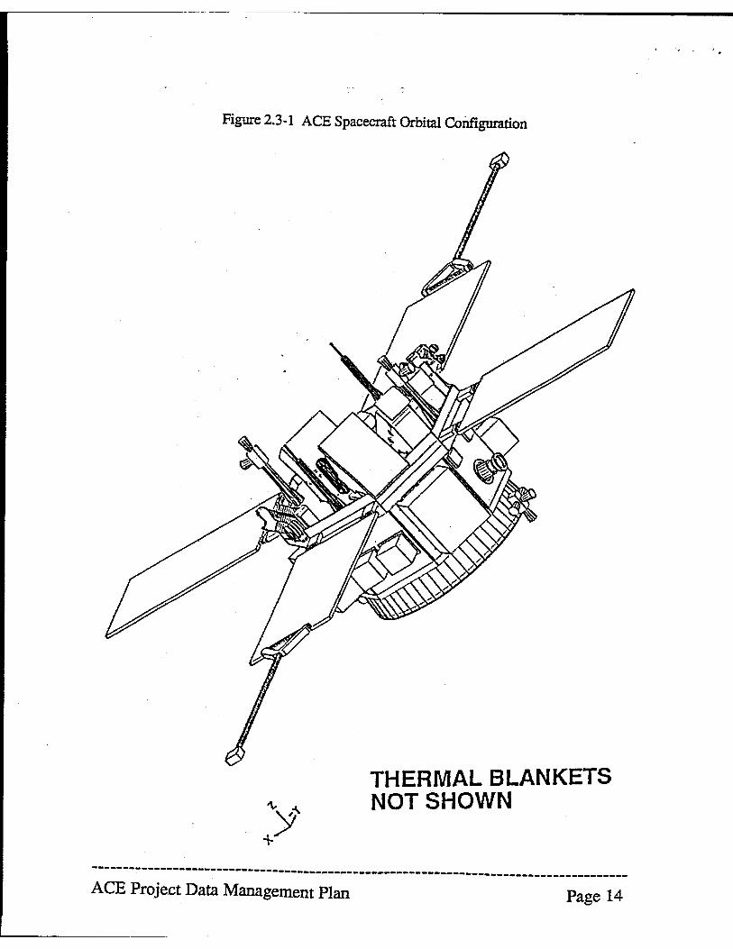
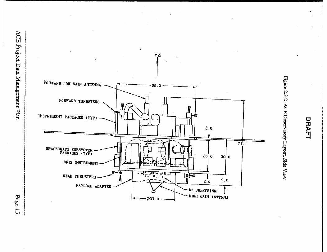
.. 2.3 Spacecraft Description
The ACE spacecraft is based on designs that evolved from the AMPTE/CCE program. The
AMPfE/CCE spacecraft was designed as a Sun-pointing mounting bus for scientific
instruments, built by APUJHU, and successfully launched in August 1984. The ACE
spacecraft body consists of a two deck, irregular octagon, 68 inches (1.73 m) across flat
to-flat (Figure 2.3-1). The decks are spaced 30 inches (0.76 m) apart, and the total height
of the spacecraft is about 72 inches (1.83 m) (Figure 2.3-2). Most of the instruments are
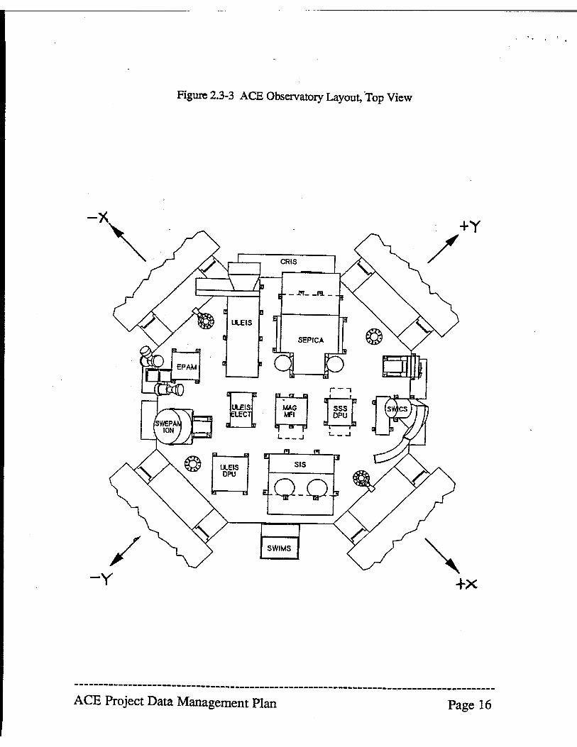
mounted to the top deck, and the four 32" by56" (0.81 m by 1.42 m) solar panel arrays are
also attached to the front deck (Figure 2.3-3). The two magnetometers are mounted on the
ends of deployment booms attached to opposite solar panels. The spacecraft subsystem
packages and the CRIS and SWIMS instruments are attached to the side panels, as are
radiators for thenna! control of the spacecraft. The rear deck supports the RF subsystem
and antennas, and the inner deck region contains the propulsion system fuel tanks.
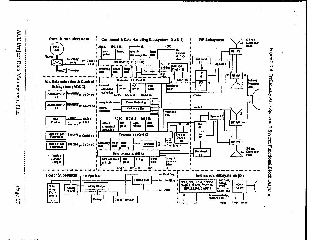
The spacecraft is to be built by the Applied Physics Laboratory of the 10hns Hopkins
University. The Preliminary ACE Spacecraft System Functional Block Diagram is shown
in Figure 2.3-4. Due to cost constraints. many of the spacecraft subsystems are single
string.
--------------------------------------------------------------------------------------ACE Project Data Management Plan Page 13
A', ...
Figure 2.3-1 ACE Spacecraft Orbital Coilfiguration
THERMAL BLANKETS NOT SHOWN
--------------------------------------------------------------------------------------ACE Project Data Management Plan Page 14
L......-_______ _
)- I I n I I
tr.I I I
~ I I
+Z 1-1 I
c9. I
t I
(I) I n I
I M- I
0 I I
~ I
S I I I
:n ~
~ I I
66.0
N
I FORWARD LOW GAIN ANTENNA § I
W
I
I
Pl I
N
I
~ I
>-
I
~ I
()
I I
tIl
I I
0 C
I
g"
~ I
:tJ
I
~
....... , INSTRUMENT PACKAGES (TYP)
):I-
§ I I I
5 " I I
~ -f
, I I I I I I
r 71.1 ~ g
I I
r
I
SPACECRAFT SUBSYSTEM
30.0
I
tn'
I
PACKAGES (TYP)
.... I
~
I I I
CRIS INSTRUMENT I I I I
<: .... 0 ~
I
9.0
I I I I I I
M' ~ RF SUBSYSTEM PAYLOAD ADAPTER I
I
Lt7I.~7 1'\ _. _ lUGU GAIN ANTENNA
I I I
~ , I
Pl , aq I
I (I) I I ,..... I
Ul I I
/ -y
Figure 2.3-3 ACE Observatory Layout, ~Top View
1:] El
CRIS
r;:;-, H
SWIMS
r-, R ~
+y
/
'" +X
-----------------------------------------------------------------~--------------------ACE Project Data Management Plan Page 16
~ ttl
~ a. CD A t:i S f s;I)
~
~ ~ ~
? ....... -..l
Propulsion Subsystem
All. Determlnallon & Conlrol Sub.Vltam (AD&e)
I AoctI~I·I"'!!!!!!ry .. e&1lH II
I Aoc:"~~t·II""'''''" e&llHn
---- anch caoo I Star lOll .. 11&2 Track. 11* cia ..
Command & Dala Handling Subsyslem (C &DH)
ADIC SIC als r-- as r;r= SIC
I 1'-'" • llmlno IlpIn dk . htlcp i
POll IUI'I pU" dala
r~cmdI
,.01, hua ...
AO&C
Paw. s'lll\tcHng
Q-cNnceflr,
(;OIJflI1nd ..... IIID1~ IIIIfI actIvabi
waldldog 1m.
~1I'I1IIr'-1''-'" cia'- .. C&DH 11 : I Command I 2 (Cmd '2) J I ~tg' ~:/lUI'Ida" .. e&OOI2 ~ :::~l;·I=~I·"q·::=nj;d~_ De;:-I EllClonlct IE ..................... n. C ................. ..-____ -'
~ 0 ... HtIndIng 12 loti 12) '~r-----------'--------r--------~-----rW-l : liming .
RF Subsystem
RX II
: CIOIIlol
CXIIIlIoI
Pa., .... allon D.nper
: I lUll" :
S·Band Quaddll .. lI,n.
S-8and .z Ouadrlldw
Htb
: IS AIlIC 8IC&f8 ~ IS : .................. , ••••• , •••••••••••••••• " ••••••••••••••••••••••••••••••••••••••• T •••••••••••••••••••••••••••••••••••••••••••••••••••••••••••••••••••••••••••••••••••••••
P)coBue ,-;:::==::::;--'''' CmcI au. Instrument SubsVSlems (IS)
c::---r-t-;::==c=:::----+--1 LOId But CAIS SIS UlEIS SEPICA· l'-l dala. ~ o.lliJ Qlarglf SWuAS. SWICS. SWEPA"':~' NOM
1..--____ LVSS EPA"'. "'''0, SWOPU CIDH 1&2 RTSW
1n11fUn .. 1lI ha,,*,. (4) IdIllOt dalol
n .. 'l>Mflf ,?/l " r.&ntt hskp cmlts
:!1
~ N W ~
~ r ~ g
I i ~, o ~.
[ t:D
~ S2
1
..
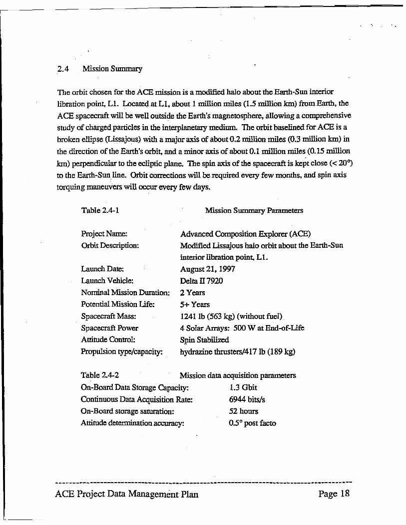
2.4 Mission Summary
The orbit chosen for the ACE mission is a modified halo about the Earth-Sun interior
libration point, Ll. Located at L1. about 1 million miles (1.5 million Ian) from Earth, the
ACE spacecraft will be well outside the Earth's magnetosphere, allowing a comprehensive
study of charged particles in the interplanetary medium. The orbit baselined for ACE is a
broken ellipse (Lissajous) with a major axis of about 0.2 million miles (0.3 million km) in
the direction of the Earth's orbit, and a minor axis of about 0.1 million miles (0.15 million
km) perpendicular to the ecliptic plane~ The spin axis of the spacecraft is kept close « 20°)
to the Earth-Sun line. Orbit corrections will be required every few months, and spin axis
torquing maneuvers will occur every few days.
Table 2.4-1 Mission Summary Parameters
Project Name: Advanced Composition Explorer (ACE)
Orbit Description: Modified Lissajous halo orbit about the Earth-Sun
interior libration point, L1.
Launch Date:
Launch Vehicle:
Nominal Mission Duration:
Potential Mission Life:
Spacecraft Mass:
Spacecraft Power
Attitude Control:
Propulsion type/capacity:
August 21, 1997
Delta II 7920
2 Years
5+ Years 1241lb (563 kg) (without fuel)
4 Solar Arrays: 500 W at End-of-Life
Spin Stabilized
hydrazine thrusters/417 lb (189 kg)
Table 2.4-2 Mission data acquisition parameters
On-Board Data Storage Capacity: 1.3 Gbit
Continuous Data Acquisition Rate: 6944 bits/s
On-Board storage saturation: 52 hours
Attitude determination accuracy: 0.5° post facto
--------------------------------------------------------------------------------------ACE Project Data Management Plan Page 18
.'
3.0 Instrument Overview
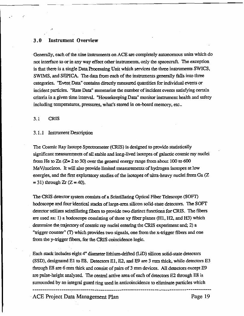
Generally, each of the nine instruments on ACE are completely autonomous units which do
not interface to or in any way effect other instruments, only the spacecraft. The exception
is that there is a single Data Processing Unit which services the three instruments SWICS,
SWIMS, and SEPICA. The data from each of the instruments generally falls into three
categories. ''Event Data" contains directly measured quantities for individual events or
incident particles. ftRate Data" summarize the number of incident events satisfying certain
criteria in a given time interval. "Housekeeping Data" monitor instrument health and safety
including temperatures, pressures. what's stored in on-board memory. etc ..
3.1 CRIS
3.1.1 Instrument Description
The Cosmic Ray Isotope Spectrometer (CRIS) is designed to provide statistically
significant measurements of all stable and long-lived isotopes of galactic cosmic ray nuclei
from He to Zn (Z= 2 to 30) over the general energy range from about 100 to 600
MeV/nucleon. It will also provide limited measurements of hydrogen isotopes at low
energies, and the first exploratory studies of the isotopes of ultra-heavy nuclei from Ga (Z
= 31) through Zr (Z = 40).
The crus detector system consists of a Scintillating Optical Fiber Telescope (SOm
hodoscope and four identical stacks of large-area silicon solid-state detectors. The SOFT
detector utilizes scintillating fibers to provide two distinct functions for CRIS. The fibers
are used as: 1) a hodoscope consisting of three xy fiber planes (HI, H2, and H3) which
determine the trajectory of cosmic ray nuclei entering the CRIS experiment and; 2) a
"trigger counter" (T) which provides two signals, one from the x-trigger fibers and one
.from the y-trigger fibers. for the CRIS coincidence logic.
Each stack includes eight 4ft diameter lithium-drifted (LiD) silicon solid-state detectors
(SSD), designated El to E8. Detectors EI, E2, and E9 are 3 mm thick, while detectors E3
through E8 are 6 mm thick and consist of pairs of 3 mm devices. All detectors except E9
are pulse-height analyzed. The central active area of each of detectors E2 through E8 is
surrounded by an integral guard ring used in anticoincidence to eliminate particles which
--------------------------------------------------------------------------------------ACE Project Data Management Plan Page 19
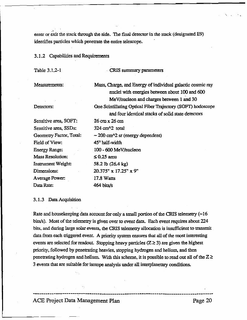
-, enter or exit the stack through the side. The final detector in the stack (designated E9)
identifies particles which penetrate the entire telescope.
3.1.2 Capabilities and Requirements
Table 3.1.2-1
Measurements:
Detectors:
Sensitive area, SOFT:
Sensitive area, SSDs:
Geometty Factor, Total:
Field of View:
Energy Range:
Mass Resolution:
Instrument Weight:
Dimensions:
Average Power:
Data Rate:
3.1.3 Data Acquisition
CRIS summary parameters
Mass, Charge, and Energy of individual galactic cosmic ray
nuclei with energies between about 100 and 600
MeV/nucleon and charges between 1 and 30
One Scintillating Optical Fiber Trajectory (SOFf) hodoscope
and four identical stacks of solid state detectors
26cmx26cm
324 cml\2 total
- 200 cml\2 st (energy dependent)
45° half-width
100 - 600 MeV/nucleon
SO.25 amu
58.2 lb (26.4 kg)
20.375" x 17.25" x 9"
17.8 Watts
464 bits/s
Rate and housekeeping data account for only a small portion of the CRIS telemetty (-16
bitsls). Most of the telemetry is given over to event data. Each event requires about 224
bits, and during large solar events, the CRIS telemetty allocation is insufficient to transmit
data from each triggered event. A priority system ensures that all of the most interesting
events are selected for readout. Stopping heavy particles (Z ~ 3) are given the highest
priority, followed by penetrating heavies, stopping hydrogen and helium, and then
penetrating hydrogen and helium. With this scheme, it is possible to read out all of the Z ~
3 events that are suitable for isotope analysis under all interplanetary conditions.
--------------------------------------------------------------------------------------ACE Project Data Management Plan Page 20
"
3.2 SIS
3.2.1 Instrument Description
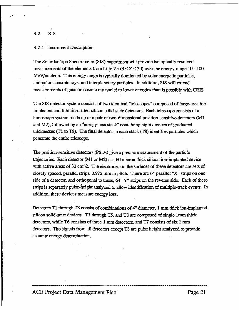
The Solar Isotope Spectrometer (SIS) experiment will provide isotopically resolved
measurements of the elements from Li to Zn (3 ~ Z ~ 30) over the energy range 10 - 100
MeV Inucleon. This energy range is typically dominated by solar energetic particles,
anomalous cosmic rays, and interplanetmy particles. In addition, SIS will extend
measurements of galactic cosmic ray nuclei to lower energies than is possible with CRIS.
The SIS detector system consists of two identical "telescopes" composed of large-area ion
implanted and lithium-drifted silicon solid-state detectors. Each telescope consists of a
hodoscope system made up of a pair of two-dimensional position-sensitive detectors (M I
and M2), followed by an "energy-loss stack" containing eight devices of graduated
thicknesses (Tl to TS). The final detector in each stack (TS) identifies particles which
penetrate the entire telescope.
The position-sensitive detectors (PSDs) give a precise measurement of the particle
trajectories. Each detector (Ml or M2) is a 60 micron thick silicon ion-implanted device
with active areas of 32 cm"2. The electrodes on the surfaces of these detectors are sets of
closely spaced, parallel strips, 0.975 mm in pitch. There are 64 parallel "X" strips on one
side of a detector, and orthogonal to these, 64 "Y" strips on the reverse side. Each of these
strips is separately pulse-height analyzed to allow identification of multiple-track events. In
addition, these devices measure energy loss.
Detectors Tl through TS consist of combinations of 4" diameter, 1 mm thick ion-implanted
silicon solid-state devices Tl through T5, and TS are composed of single Imm thick
detectors, while T6 consists of three 1 mm detectors, and T7 consists of six. 1 mm
detectors. The signals from all detectors except TS are pulse height analyzed to provide
accurate energy determination.
--------------------------------------------------------------------------------------ACE Project Data Management Plan Page 21
3.2.2 Capabilities and Requirements
Table 3.2.2-1
Measurements:
Detectors:
Sensitive area
Geometry Factor, Total:
Field of View:
Energy Range:
Mass Resolution:
Instrument Weight;
Dimensions:
Average Power:
Data Rate:
3.2.3 Data Acquisition
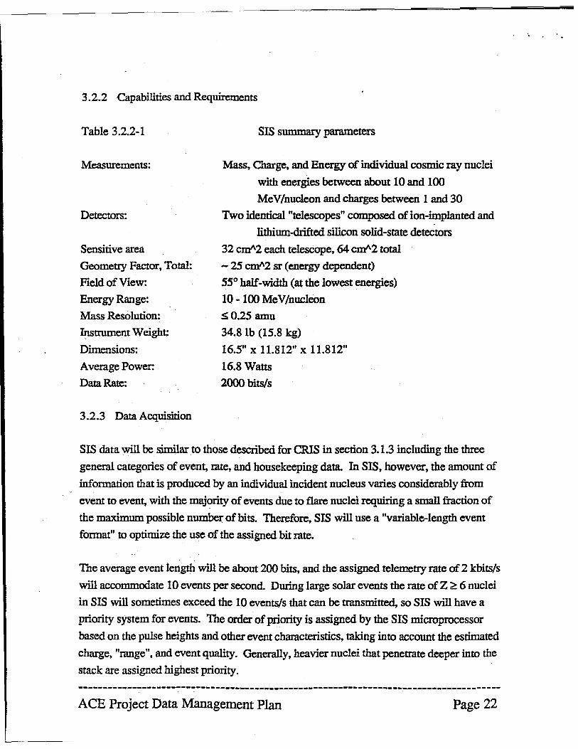
SIS summary parameters
Mass, Charge, and Energy of individual cosmic ray nuclei
with energies between about 10 and 100
MeV/nucleon and charges between 1 and 30
Two identical "telescopes" composed of ion-implanted and
lithium-drifted silicon solid-state detectors
32 CJJl"\2 each telescope, 64 CJJl"\2 total
- 25 CJJl"\2 sr (energy dependent)
55° half-width (at the lowest energies)
10 - 100 Me V/nucIeon
SO.25 amu
34.8 lb (15.8 kg)
16.5" x 11.812" x 11.812"
16.8 Watts
2000bits/s
SIS data will be similar to those described for crus in section 3.1.3 including the three
general categories of event, mte, and housekeeping data. In SIS, however, the amount of
information that is produced by an individual incident nucleus varies considerably from
event to event, with the majority of events due to flare nuclei requiring a small fraction of
the maximum possible number of bits. Therefore, SIS will use a "variable-length event
format" to optimize the use of the assigned bit rate.
The average event length will be about 200 bits, and the assigned telemetry rate of 2 kbits/s
will accommodate 10 events per second. During large solar events the rate of Z ~ 6 nuclei
in SIS will sometimes exceed the 10 events/s that can be tmnsmitted, so SIS will have a
priority system for events. The order of priority is assigned by the SIS microprocessor
based on the pulse heights and other event characteristics, taking into account the estimated
charge, "mnge", and event quality. Generally, heavier nuclei that penetmte deeper into the
stack are assigned highest priority.
------------------------------------------------------------------~-------------------
ACE Project Data Management Plan Page 22
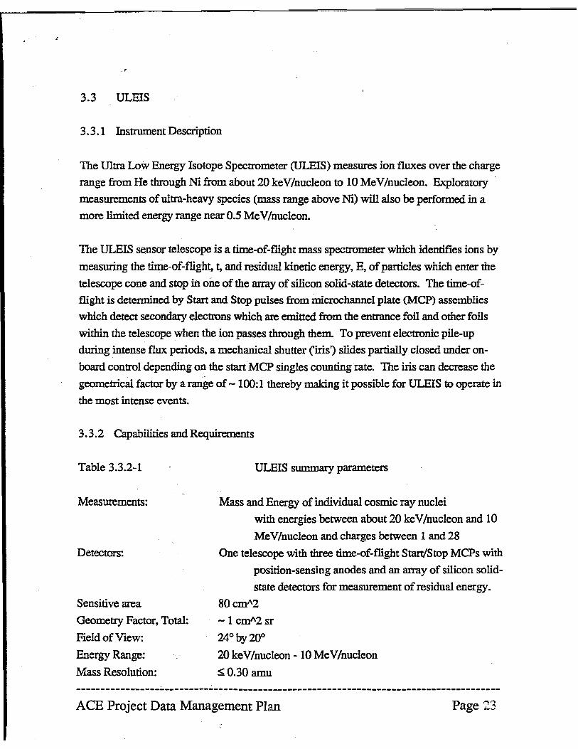
3.3 ULEIS
3.3.1 Instrument Description
The IDtra Low Energy Isotope Spectrometer (ULElS) measures ion fluxes over the charge
range from He through Ni from about 20 keY/nucleon to 10 MeV/nucleon. Exploratory .
measurements of ultra-heavy species (mass range above Ni) will also be performed in a
more limited energy range near 0.5 MeV/nucleon.
The ULEIS sensor telescope is a rlme-of-flight mass spectrometer which identifies ions by
measuring the time-of-flight, t, and residual kinetic energy, E, ofparticles which enter the
telescope cone and stop in one of the array of silicon solid-state detectors. The time-of
flight is determined by Start and Stop pulses from inicrochannel plate (MCP) assemblies
which detect secondary electrons which are emitted from the entrance foil and other foils
within the telescope when the ion passes through them. To prevent electronic pile-up
during intense flux periods. a mechanical shutter ('iris') slides partially closed under on
board control depending on the stan MCP singles counting rate. The iris can decrease the
geometrical factor by a range of - 100:1 thereby making it possible for ULEIS to operate in
the most intense events.
3.3.2 Capabilities and Requirements
Table 3.3.2-1
Measurements:
Detectors:
Sensitive area
Geometry Factor, Total:
Field of View:
Energy Range:
Mass Resolution:
ULEIS snmmary parameters
Mass and Energy of individual cosmic ray nuclei
with energies between about 20 ke V /nucleon and 10
MeV/nucleon and charges between 1 and 28
One telescope with three time-of-flight Start/Stop MCPs with
position-sensing anodes and an array of silicon solid
state detectors for measurement of residual energy.
80cmA2 -1 cmA2sr
24° by 20°
20 keY/nucleon - 10 MeV/nucleon
SO.30 amu
--------------------------------------------------------------------------------------ACE Project Data Management Plan
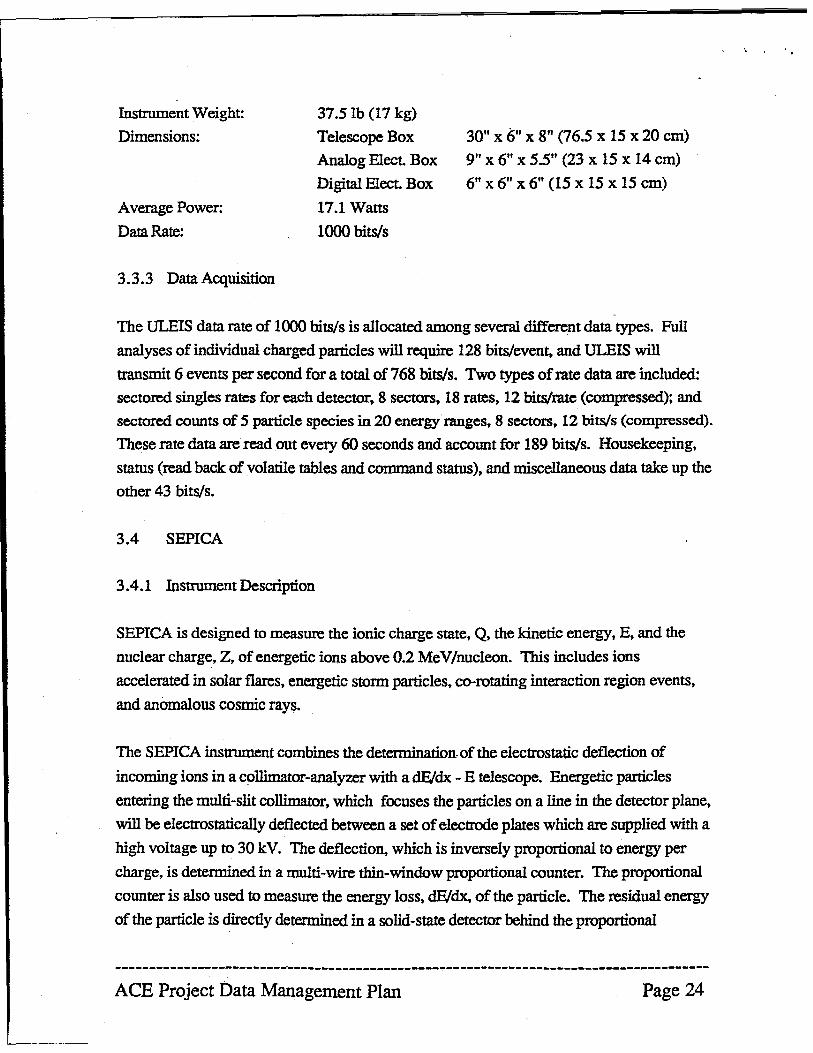
Instrument Weight:
Dimensions:
Average Power:
Data Rate:
3.3.3 Data Acquisition
37.5 Ib (17 kg)
Telescope Box
Analog Elect Box
Digital Elect Box
17.1 Watts
1000 bits/s
30" x 6" X 8ft (76.5 x 15 x 20 cm)
9" x 6" X 5.5" (23 x 15 x 14 cm)
6" x 6" X 6" (15 x 15 x 15 cm)
The ULEIS data rate of 1000 bits/s is allocated among several different data types. Full
analyses of individual charged particles will require 128 bits/even~ and ULEIS will
transmit 6 events per second for a total of 768 bits/so Two types of rate data are included:
sectored singles rates for each detector, 8 sectors, 18 rates, 12 bits/rate (compressed); and
sectored counts of 5 particle species in 20 energy ranges, 8 sectors, 12 bits/s (compressed).
These rate data are read out every 60 seconds and account for 189 bits/so Housekeeping,
status (read back of volatile tables and command status), and miscellaneous data take up the
other 43 bits/so
3.4 SEPICA
3.4.1 Instrument Description
SEPlCA is designed to measure the ionic charge state, Q, the kinetic energy, E, and the
nuclear charge, Z, of energetic ions above 0.2 MeV/nucleon. This includes ions
accelerated in solar flares, energetic storm particles. co-rotating interaction region events,
and anomalous cosmic rays.
The SEPICA instrument combines the determination. of the electrostatic deflection of
incoming ions in a collimator-analyzer with a dFJdx - E telescope. Energetic particles
entering the multi-slit collimator, which focuses the particles on a line in the detector plane,
will be electrostatically deflected between a set of electrode plates which are supplied with a
high voltage up to 30 kV. The deflection, which is inversely proportional to energy per
charge, is determined in a multi-wire thin-window proportional counter. The proportional
counter is also used to measure the energy loss, dE/dx, of the particle. The residual energy
of the particle is directly determined in a solid-state detector behind the proportional
--------------------------------------------------------------------------------------ACE Project Data Management Plan Page 24
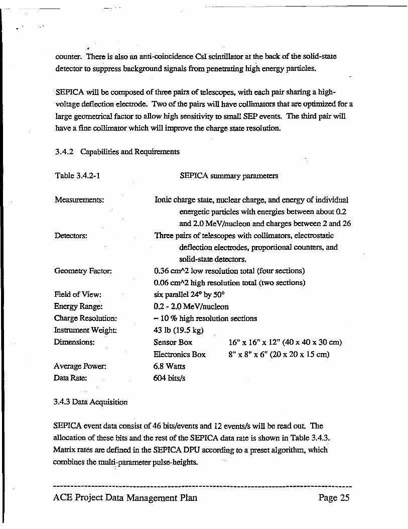
·. counter. There is also an anti-coincidence Csi scintillator at the back of the solid-state
, detector to suppress background signals from penetrating high energy particles .
. SEPICA will be composed of three pairs of telescopes, with each pair sharing a high
voltage deflection electrode. Two of the pairs will have collimators that are optimized for a
large geometrical factor to allow high sensitivity to small SEP events. The third pair will
have a fine collimator which will improve the charge state resolution.
3.4.2 Capabilities and Requirements
Table 3.4.2-1
Measurements:
Detectors:
Geometry Factor:
Field of View:
Energy Range:
Charge Resolution:
Instrument Weight:
Dimensions:
Average Power:
Data Rate:
3.4.3 Data Acquisition
SEPlCA snmmary parameters
Ionic charge state, nuclear charge, and energy of individual
energetic particles with energies between about 0.2
and 2.0 MeV/nucleon and charges between 2 and 26
Three pairs of telescopes with collimators, electrostatic
deflection electrodes, proportional counters, and
solid-state detectors.
0.36 cm"210w resolution total (four sections)
0.06 cm"2 high resolution total (two sections)
six parallel 24° by 50°
0.2 - 2.0 MeV/nucleon
- 10 % high resolution sections
43 lb (19.5 kg)
Sensor Box
Electronics Box
6.8 Watts
604 bits/s
16" x 16" x 12" (40 x 40 x 30 cm)
8" x 8" x 6" (20 x 20 x 15 cm)
SEPICA event data consist of 46 bits/events and 12 events/s will be read out The
allocation of these bits and the rest of the SEPlCA data rate is shown in Table 3.4.3.
Matrix rates are defined in the SEPlCA DPU according to a preset algorithm. which
combines the multi-parameter pulse-heights.
--------------------------------------------------------------------------------------ACE Project Data Management Plan Page 25
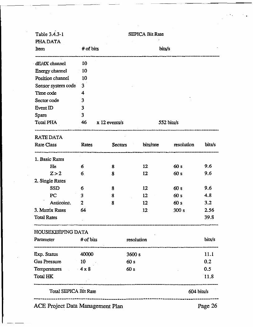
, Table 3.4.3-1
PHADATA
Item
dEJdX channel
Energy channel
Position channel
Sensor system code
Time code
Sector code
EventID
Spare
TotalPHA
SEPICA Bit Rate
#ofbits bits/s
10
10
10
3
4
3
3
3
46 x 12 events/s 552 bits/s
RATE DATA
Rate Class Rates Sectors bits/rate resolution bits/s
1. Basic Rates
He 6
Z>2 6 2. Single Rates
SSD 6 PC 3 Anticoinc. 2
3. Matrix Rates 64
Total Rates
HOUSEKEEPING DATA
Parameter
Exp. Status
Gas Pressure
Temperatures
TotalHK
# of bits
40000
10
4xS
8
8
8 8
8
12
12
12 12 12 12
resolution
3600s
60s
60s
60s
60s
60s
60s
60s
300 s
9.6
9.6
9.6 4.8 3.2 2.56 39.S
bits/s
11.1
0.2 0.5
11.S -----------------------------------------------------------------------------------------------------------
Total SEPICA Bit Rate 604 bits/s
--------------------------------------------------------------------------------------ACE Project Data Management Plan Page 26
· '.
."
" ,
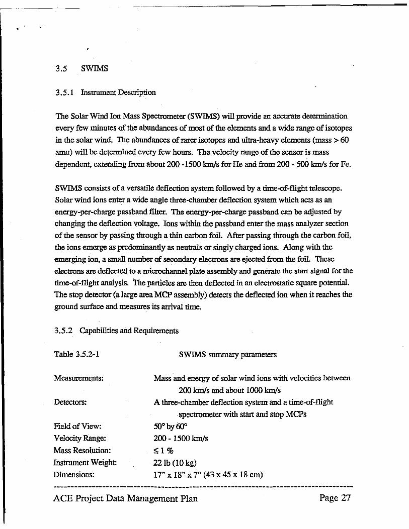
3.5 SWIMS
3.5.1 Instrument Description
The Solar Wind Ion Mass Spectrometer (SWIMS) will provide an accurate determination
every few minutes of the abundances of most of the elements and a wide range of isotopes
in the solar wind. The abundances of rarer isotopes and ultra-heavy elements (mass> 60
amu) will be determined every few hours. The velocity range of the sensor is mass
dependent, extending from about 200 -1500 km/s for He and from 200 - 500 km/s for Fe.
SWIMS consists of a versatile deflection system followed by a time-of-flight telescope.
Solar wind ions enter a wide angle three-chamber deflection system which acts as an
energy-per-charge passband filter. The energy-per-charge passband can be adjusted by
changing the deflection voltage. Ions within the passband enter the mass analyzer section
of the sensor by passing through a thin carbon foil. After passing through the carbon foil,
the ions emerge as predominantly as neutrals or singly charged ions. Along with the
emerging ion, a small number of secondary electrons are ejected from the foil. These
electrons are deflected to a microchannel plate assembly and generate the start signal for the
time-of-flight analysis. The particles are then deflected in an electrostatic square potential.
The stop detector (a large area MCP assembly) detects the deflected ion when it reaches the
ground surface and measures its arrival time.
3.5.2 Capabilities and Requirements
Table 3.5.2-1
Measurements:
Detectors:
Field of View:
Velocity Range:
Mass Resolution:
Instrument Weight:
Dimensions:
SWIMS summary parameters
Mass and energy of solar wind ions with velocities between
200 km/s and about 1000 km/s
A three-chamber deflection system and a time-of-flight
spectrometer with start and stop MCPs
SO°byfIJo
200 - 1500 km/s
~1%
22lh (10 kg)
17" x 18" x 7" (43x 45 x 18 cm)
--------------------------------------------------------------------------------------ACE Project Data Management Plan Page 27
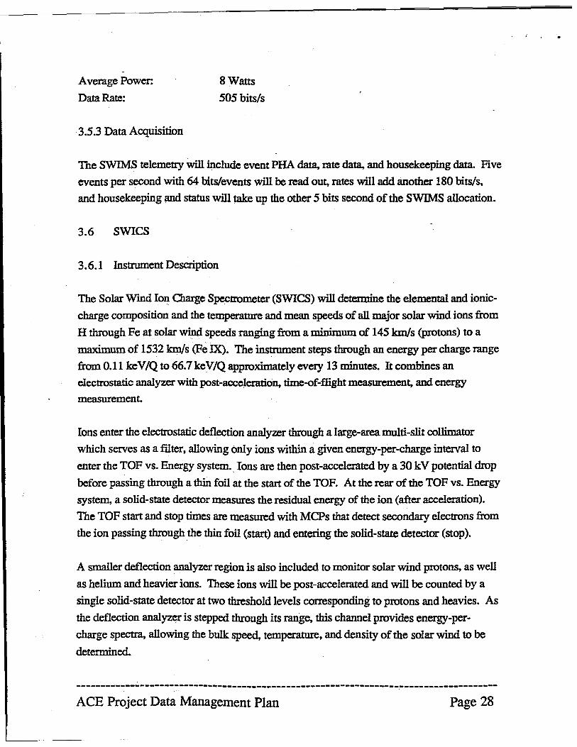
Average Power:
Data Rate:
3.5.3 Data Acquisition
8 Watts
505 bits/s
The SWIMS telemetry will include event PHA data, rate data, and housekeeping data. Five
events per second with 64 bits/events will be read ou~ rates will add. another 180 bits/s,
and housekeeping and status will take up the other 5 bits second of the SWIMS allocation.
3.6 SWICS
3.6.1 Instrument Description
The Solar Wmd Ion Charge Spectrometer (SWICS) will determine the elemental and ionic
charge composition and the temperature and mean speeds of all major solar wind ions from
H through Fe at solar wind speeds ranging from a minimum of 145 km/s (protons) to a
maximum of 1532 km/s (Fe lX). The instrument steps through an energy per charge range
from 0.11 keV/Q to 66.7 keV/Q approximately every 13 minutes. It combines an
electrostatic analyzer with post-acceleration, time-of-flight measuremen~ and energy
measurement.
Ions enter the electrostatic deflection analyzer through a large-area multi-slit collimator
which serves as a filter, allowing only ions within a given energy-per-charge interval to
enter the TOF vs. Energy system. Ions are then post-accelerated by a 30 kV potential drop
before passing through a thin foil at the start of the TOP. At the rear of the TOF vs. Energy
system, a solid-state detector measures the residual energy of the ion (after acceleration).
The TOF start and stop times are measured with MCPs that detect secondary electrons from
the ion passing through ,the thin foil (start) and entering the solid-state detector (stop).
A smaller deflection analyzer region is also included to monitor solar wind protons, as well
as helium and heavier ions. These ions will be post-accelerated and will be counted by a
single solid-state detector at two threshold levels corresponding to protons and heavies. As
the deflection analyzer is stepped through its range, this channel provides energy-per
charge spectra, allowing the bulk speed, temperature, and density of the solar wind to be
detennined.
------------------------------------------------------------------~-------------------
ACE Project Data Management Plan Page 28
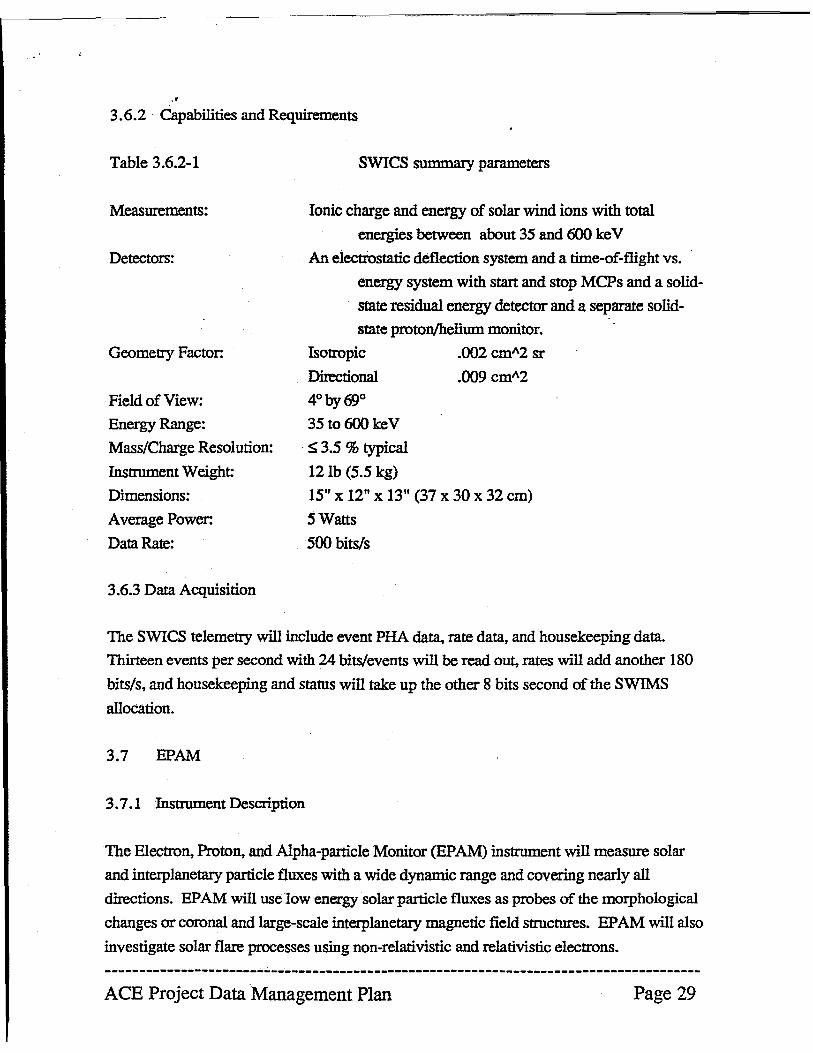
.. 3.6.2 Capabilities and Requirements
Table 3.6.2-1
Measurements:
Detectors:
Geometry Factor:
Field of View:
Energy Range:
Mass/Charge Resolution:
Instrument Weight:
Dimensions:
Average Power:
Data Rate:
3.6.3 Data Acquisition
SWICS summary parameters
Ionic charge and energy of solar wind ions with total
energies between about 35 and 600 ke V
An electrostatic deflection system and a time-of-flight vs.
energy system with start and stop MCPs and a solid
state residual energy detector and a separate solid
state prOton/helium monitor.
Isotropic .002 eml\2 sr
Directional .009 cml\2
4° by 69° 35to600keV
S 3.S % typical
12 lb (5.5 kg)
15" x 12" x 13" (37 x 30 x 32 cm)
SWatts
SOO bits/s
The SWICS telemetry will include event PHA data, rate data, and housekeeping data.
Thirteen events per second with 24 bits/events will be read out, rates will add another 180
bits/s, and housekeeping and status will take up the other 8 bits second of the SWIMS
allocation.
3.7 EPAM
3.7.1 Instrument Description
The Electron, Proton, and Alpha-particle Monitor (EPAM) instrument will measure solar
and interplanetary particle fluxes with a wide dynamic range and covering nearly all
directions. EPAM will use low energy solar particle fluxes as probes of the morphological
changes or coronal and large-scale interplanetary magnetic field structures. EP AM will also
investigate solar flare processes using non-relativistic and relativistic electrons.
--------------------------------------------------------------------------------------ACE Project Data Management Plan Page 29
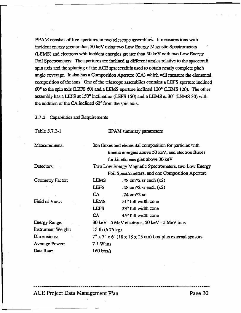
EP AM consists of five apertures in two telescope assemblies. It measures ions with
incident energy greater than 50 ke V using two Low Energy Magnetic Spectrometers
(LEMS) and electrons with incident energies greater than 30 keV with two Low Energy
Foil Spectrometers. The apertures are inclined at different angles relative to the spacecraft
spin axis and the spinning of the ACE spacecraft is used to obtain nearly complete pitch
angle coverage. It also has a Composition Apertme (CA) which will measure the elemental
composition of the ions. One of the telescope assemblies contains a LEFS aperture inclined
60° to the spin axis (LEFS 60) and a LEMS apertme inclined 120° (LEMS 120). The other
assembly has a LEFS at 150° inclination (LEFS ·150) and a LEMS at 30° (LEMS 30) with
the addition of the CA inclined 60° from the spin axis.
3.7.2 Capabilities and Requirements
Table 3.7.2-1
Measurements:
Detectors:
Geometry Factor:
Field of View:
Energy Range:
Instrument Weight:
Dimensions:
Average Power:
Data Rate:
EP AM summary parameters
Ion fluxes and elemental composition for particles with
kinetic energies above 50 keY, and electron fluxes
for kinetic energies above 30 keY
Two Low Energy Magnetic Spectrometers, two Low Energy
Foil Spectrometers, and one Composition Aperture
LEMS .48 cm"2 sr each (x2)
LEFS
CA LEMS
.48 cm"2 sr each (x2)
.24cm"2 sr
510 full width cone
LEFS 53° full width cone
CA 45° full width cone
30 ke V - 5 MeV electrons, 50 ke V - 5 MeV ions
151b (6.75 kg)
7" x 7" X 6ft (18 x 18 xiS cm) box plus external sensors
7.1 Watts
160 bits/s
--------------------------------------------------------------------------------------ACE Project Data Management Plan Page 30
" , 3.7.3 Data Acquisition
The EP AM data rate is 168 bits per second including science data and digital housekeeping
data. There are also four analog housekeeping lines to be sampled once every 32 seconds.
3.8 SWEPAM
3.8.1 Instrument Description
The Solar Wmd Electron, Proton. and Alpha Monitor (SWEP AM) will measure low energy
solar wind electron fluxes from 1 to 900 eV and ion fluxes between 0.26 and 35 KeV.
SWEP AM will be composed of spare Los Alamos solar wind electron and ion analyzers
from the lliysses mission.
Both sensors make use of curved-plate electrostatic analyzers (ESAs) which are spherical
sections cut off in the form of a sector. Biased channel electron multipliers (CEMs) are
spaced alone the exit apertures of the ESAs for ion and electron detection. Different CEMs
sample different portions of the fan-shaped fields-of view.
The ion sensor consists of a 1050 bending angle ESA with an average radius of 100 mm
and a plate spacing of 2.84 mm. 16 CEMs contiguously spaced along the exit gap of the
ESA give - 50 polar angular resolution over the -850 acceptance fan.
The electron sensor consists of a 1200 bending angle ESA with an average radius of 41.9
mm and a plate spacing of 3.5 mm. Seven large-funnel CEMs along the exit gap give - 200
polar angular resolution over a 1600 fan.
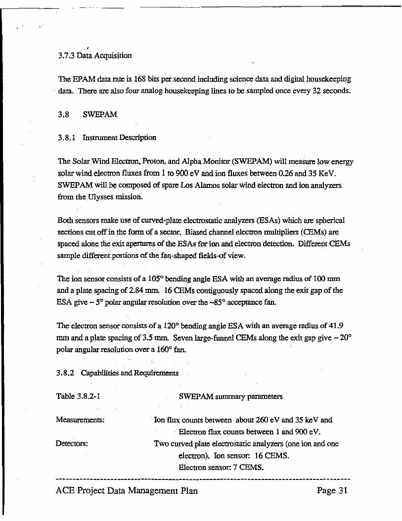
3.8.2 Capabilities and Requirements
Table 3.8.2-1
Measurements:
Detectors:
SWEPAM summary parameters
Ion flux. counts between about 260 e V and 35 ke V and
Electron flux. counts between 1 and 900 eVe
Two curved plate electrostatic analyzers (one ion and one
electron). Ion sensor: 16 CEMS.
Electron sensor: 7 CEMS.
ACE Project Data Management Plan Page 31
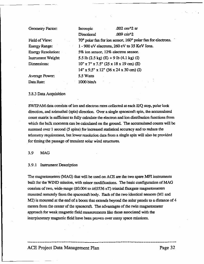
Geometry Factor:
Field of View:
Energy Range:
Energy Resolution:
Instrument Weight:
Dimensions:
Average Power:
Data Rate:
3.8.3 Data Acquisition
Isotropic
Directional
70° polar fan for ion sensor, 160° polar fan for electrons.
1 - 900 e V electrons, 260 e V to 35 KeV Ions.
5% ion sensor. 12% electron sensor.
5.51b (2.5 kg) (E) + 91b (4.1 kg) (I)
10" x 7" X 7.5" (25 x 18 x 19 em) (E)
14" x 95ft x 12"(36 x 24 x 30 em) (I)
5.5 Watts
1000 bits/s
SWEP AM data consists of ion and electron rates collected at each ElQ stop, polar look
direction. and azimuthal (spin) direction. OVer a single spacecraft spin, the accumulated
count matrix is sufficient to fully calculate the electron and ion distribution functions from
which the bulk moments can be calculated on the ground. The accumulated counts will be
summed over 1 second (5 spins) !or increased statistical accuracy and to reduce the
telemetry requirement, but lower resolution data from a single spin will also be provided
for timing the passage of transient solar wind structures.
3.9 MAG
3.9.1 Instrument Description
The magnetometers (MAG) that will be used on ACE are the two spare MFI instruments
built for the WIND mission, with minor modifications. The basic configuration of MAG
consists of two, wide-range (±o.OO4 to ±65536 nT) triaxialfIuxgate magnetometers
mounted remotely from the spacecraft body. Each of the two identical sensors (M1 and
M2) is mounted at the end of a boom that extends beyond the solar panels to a distance of 4
meters from the center of the spacecraft. The advantages of the twin magnetometer
approach for weak magnetic field measurements like those associated with the
interplanetary magnetic field have been proven over many space missions.
--------------------------------------------------------------------------------------ACE Project Data Management Plan Page 32
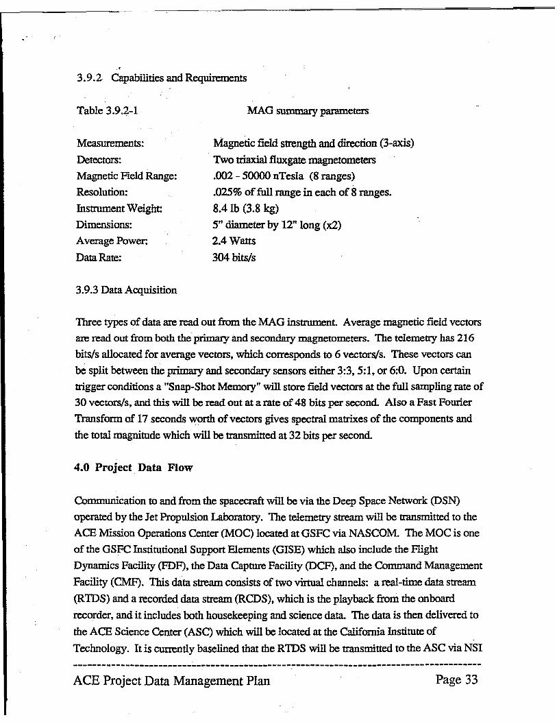
3.9.2 Capabilities and Requirements
Table 3.9.2-1
Measurements:
Detectors:
Magnetic Field Range:
Resolution:
Instrument Weight:
Dimensions:
Average Power:
Data Rate:
3.9.3 Data Acquisition
MAG summary parameters
Magnetic field strength and direction (3-axis)
Two triaxial fluxgate magnetometers
.002 - 50000 nTesla (8 ranges)
.025% of full range in each of 8 ranges.
8.4 lb (3.8 kg)
5" diameter by 12" long (xl)
2.4 Watts
304 bits/s
Three types of data are read out from the MAG instrument. Average magnetic field vectors
are read out from both the primary and secondary magnetometers. The telemetry has 216
bits/s allocated for average vectors, which corresponds to 6 vectors/so These vectors can
be split between the primary and secondary sensors either 3:3,5:1, or 6:0. Upon certain
trigger conditions a "Snap-Shot Memory" will store field vectors at the full sampling rate of
30 vectors/s, and this will be read out at a rate of 48 bits per second. Also a Fast Fourier
Transform of 17 seconds worth of vectors gives spectral matrixes of the components and
the total magnitude which will be transmitted at 32 bits per second.
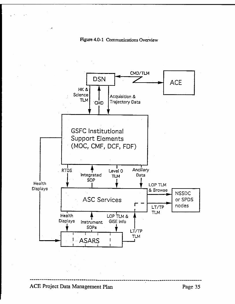
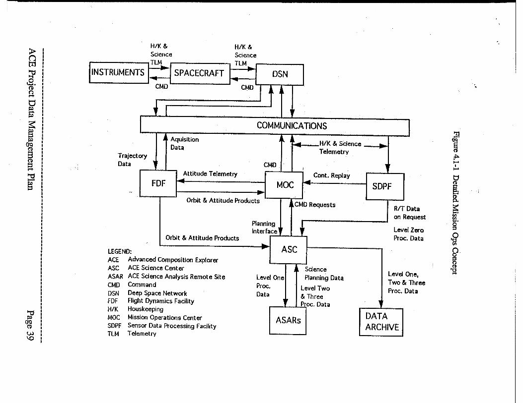
4.0 Project Data Flow
Communication to and from the spacecraft will be via the Deep Space Network (DSN)
operated by the Jet Propulsion Laboratory. The telemetry stream will be transmitted to the
ACE Mission Operations Center (MOC) located at GSFC via NASCOM. The MOe is one
of the GSFC Institutional Support Elements (GISE) which also include the Flight
Dynamics Facility (FDF), the Data Capture Facility (DCF), and the Command Management
Facility (eMF). This data stream consists of two virtual channels: a real-time data stream
(RIDS) and a recorded data stream (RCDS), which is the playback from the onboard
recorder, and it includes both housekeeping and science data. The data is then delivered to
the ACE Science Center (AS C) which will be located at the California Institute of
Technology. It is currently baselined that the RIDS will be transmitted to the ASC via NSI
--------------------------------------------------------------------------------------ACE Project Data Management Plan Page 33
."
with the TCPIIP protocol. The RCDS will be delivered to the ASC via 4 mm tape sent
through ·the mail. The ASC is responsible for processing the'data to level! and generating
the browse files. It is then the responsibility of the ASC to distribute the data to the science
co-investigators at ACE Science Analysis Remote Sites (ASARS). The data is then
processed at the ASARS and higher level data is retmned to the ASC for local archiving
and eventual transferal to the National Space Science Data Center (NSSDC).
Command requests will be forwarded (generally electronically) from the instrument facility
to the ASC for coordination and conflict resolution. Integrated command files will then be
forwarded to the GISE in a manner TBD. The actual command flles are senno the ACE
spacecraft (via DSN) by the GISE. It should be noted that ACE is not an "active"
observatory. and that, except for the turn-on peri~ instrument commands will be rather
infrequent.
--------------------------------------------------------------------------------------ACE Project Data Management Plan Page 34
Health Displays
..
I
Figure 4.0-1 Communications Overview
DSN HK & ~
CMDITLM
L
Science Acquisition &
TLM 'CMD Trajectory Data
, , I ' r
GSFC Institutional Support Elements (MOC, CMF, DCF, FDF)
+ Integrated SOP
Lev!1 0 TLM
Anciilary Data
I + t LOP TLM & Browse
ASC Services r-LT/TP
+ LOPTLM & TLM
Hearth .~
isplays Instrument SOPs
D
t 1 ASARS
GISE Info
t LT/TP TLM
ACE
NSSDC or SPDS nodes
--------------------------------------------------------------------------------------ACE Project Data Management Plan Page 35
g ~ ~. (I) o !"'t'
o S ~ j fa ~ ~
~ w 0'\
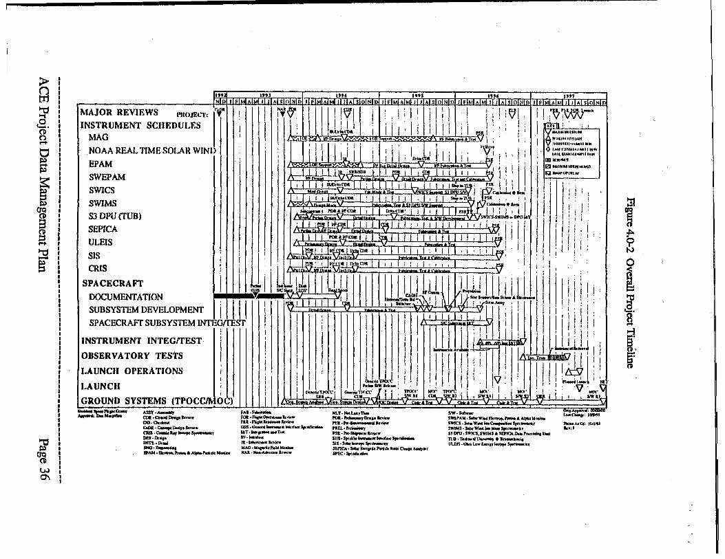
rm~L__ _.,,~" __ ,J ~,~ l'~~ 1995 U" ."1 111101 i[fJI!!lATMiiliL~L~lflll!lorJlfTMlM!o1I!1 II Al sJ611i1olllF1Mr..i.IMIJl IlAI slolNlol JlFIMIAIMI 11 JUIsI()INIOI JlFIr;t{AIMI II II AI slOIN
MAJOR REVIEWS 'Cl1l/1 I'ROJECT: J T
INSTRUMENT SCHEDULES MAG NOAA REAL l1MESOLAR WIND BPAM SWEPAM SWICS SWIMS
S3 DPU(TUB)
I ; I 1 I , I
\11\11 i : i ! : I! II! I ; Ii! ~I; I! t~!~· lill ," j I '!: I, Ii rni :,
,JMJ."I1>k I I J I ,II I I ! i : I m I :. ! I I y ...... "',.,. ... • - , .... 1/1- ~'~:J!,.5J Ii· i I tl."J.IU'~"'Md'
I I' I'" 1 ' . L ' ,,'V """'""''',,.,,
I 1..1,' J' i I' :1 ' I· I" I:, 'I' ''i!{J,:, Ii; 0 :':~f!.":'~~::::''' ~jL, I) Ilolto 1 I, 01 I ,,' IIQ .... IM$
h.. V. I 'I: 1 III .. , ..... "' ..... "'p I i Jl. :stltJSPa I ,~I ,OlI I I I I 1 I ~ I ! ' I Ea _ .. ...,AY
.... V\. " ;7 " I I I ~ .. coa I I ' Ii'! I ; I SIOp"'!l!J' , ~'k, III I Ii': ..... ", • ' , oPilWN I· Cali ..... . I Ii,
! , I ' I I 1~"CIlIl' I ; I i I I I , ,: I """TlL~i 'I'SR, ;! i} II II,! i " V ~ ...... , I ,"
I ,~I l'Ila.!-wCoa I I I IloltolllK' iii I I IT ... ;J I I : f, ! i ! Ii! ~ '., • .nI'SoSW-"'IlrIJIII, ,i.
NAl~ I" I I " , I I I: I .' I
::.! i~ I w,lJll1 I I i I 1'Jil1 i ! I! iii , I I I I~ I iii I iii; i ULEIS I I' II I ~ I I ,oU..1fCllllI 1.1 ~ " II I I i I 11 i 1 1# ~ ! ,! i II! i;!:
S 1 'i 1'OIt111'1!.J!IIJII!tCmllllllii ;111 ""'lm;,I! ,!,j!,'
IS I I ' '\j;; ~v.-~, I." ,i " '
S~ECItAFT I I L II brb~1 wf"i i I illl] lJii ';).LlJ .illill i i; I : Iii iii
SEPICA
DOCUMENTATION :~ II ~ ! irJ'G'l! I I IV(~ I "~~ \'l!1 M~ ~~ . ..:.-:,,"~-. , , . I i I : : SUBSYSTEM DEVELOPMENT I I I I : ; ! I I ' !: !
I I i I I II;, 'I . ! ii'
SPACECRAFf SUBSYSTEM INTE9 ST! I i I I !! I 1 \ I ! I ! II I II! II ! ! INSTRUMENT INTEGITEST Ii ! ,I I 'I I lL.U I~, ~ I I " I W.l1, I OBSERVATORY TESTS i I I I I II I J II! ;T' I II Y. - "~~ 11'1: (.AUNCH OPERATIONS i I' i II! ,~.r :,1 1.1 I I i I, ,I i ' I I~: i 1111'g,J ~ l AUNCH j I I ',I , ....... ]---. ' " ,!" I I J I ' .: ! I !. ,n. t"
oJ ,I ,I. •• TrOC'C Nl'X" Tfl(K' ...,.. MClI'. I' V NO(" \I ! 1 II i ~Tr~i a. ..... a:-ILT ! I : JiWII <iii _i&':ll I i sN.llJ iii s/Ul w U_i 1 . , WI'
GROUND SYSTEMS (TPOCe/1\! OC) I at ... D"j 1kUo.J£ c .... n ... .J/..J£ C ..... T... <' .... .IT.M~ ~ _".. ...... ee.. "-"'0.. ... .....
AS$Y._, a.·ca_llnoa. __ 00.0. ..... ~·~ .... I· ..... • CIIS.~..,.....,.s,.-.. DES· 0. ... DEn· a...! ENO,~_, IPAM ·Ek_ "-AAljoM-rn ... _
PAJ·_ FOIl· AIs" Opa ............. fU·Ri,,,,_._ IHIS.o-... _ ..... If_~ IAT ...... _ ... T .. w·"",~ ... .. ~~ •• v ... WAO ..... __ _
NAt. Now-A*oc:a. Jt.cMw
NLT·IIoclotot,..., POa·""'_ ........ ... ra· .... _ .... ...... .. a·......, rsa .... .SIoipootM ...... w SII5."",_'_ .. '."",,,,,,_ SIS • w. .... Sprew.e .. , SIEI'ICA·s.o.-... ...... "' ... a...I • ....., .. ' S/'EC."", .. _
onl~aI.: DOOWI
~~!':c~"w"'Ek""".""",""_"_ ..... C>u .. ' 1_1 SWICS.SoIotW ... IooC ........ ~ _"''''' ,Gi.,,1 SWI"S· SoW"' ..... "-s,...-", "d 51 1l"J. $WIC$.5W1MS .. $EI'ICA _ "'-ooiotlloio TUJ ·T"dlw"~. an-nril 1JU1S·IlIwoLowEa.·arloooopo ""'~.,
:n ~ ~
<? tv
! & a ~ ~'
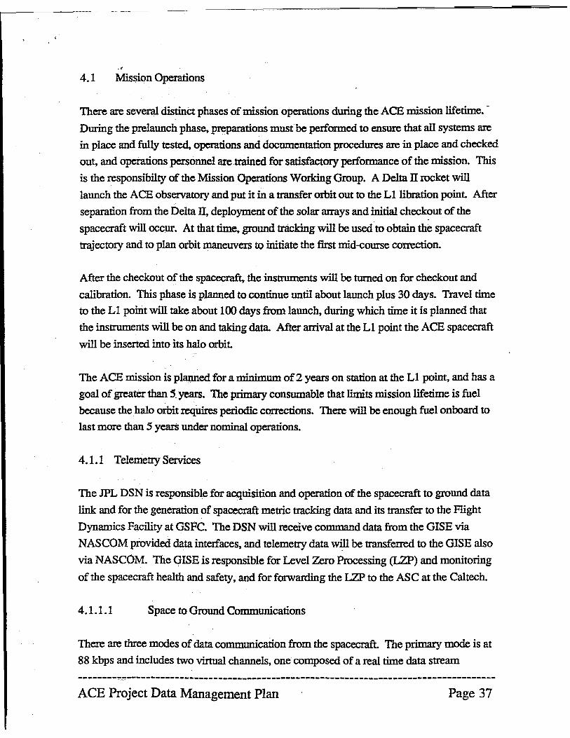
., 4.1 Mission Operations
There are several distinct phases of mission operations during the ACE mission lifetime. -
During the prelaunch phase, preparations must be performed to ensure that all systems are
in place and fully tested, opemtions and documentation procedures are in place and checked
out, and operations personnel are trained for satisfactory performance of the mission. This
is the responsibilty of the Mission Operations Working Group. A Delta JI rocket will
launch the ACE observatory and put it in a transfer orbit out to the Ll libration point. After
separation from the Delta ]J, deployment of the solar arrays and initial checkout of the
spacecraft will occur. At that time, ground tracking will be used to obtain the spacecraft
trajectory and to plan orbit maneuvers to initiate the first mid-course correction.
After the checkout of the spacecraft, the instruments will be turned on for checkout and
calibration. This phase is planned to continue until about launch plus 30 days. Travel time
to the Ll point will take about 100 days from launch, during which time it is planned that
the instruments will be on and taking data. After arrival at the Ll point the ACE spacecraft
will be inserted into its halo orbit.
The ACE mission is planned for a minimum of2 years on station at the Ll point, and has a
goal of greater than 5 years. The primary consumable that limits mission lifetime is fuel
because the halo orbit requires periodic corrections. There will be enough fuel onboard to
last more than 5 years under nominal operations.
4.1.1 Telemetry Services
The JPL DSN is responsible for acquisition and operation of the spacecraft to ground data
link and for the generation of spacecraft metric tracking data and its transfer to the Flight
Dynamics Facility at GSFC. The DSN will receive command data from the GISE via
NASCOM provided data interfaces, and telemetry data will be transferred to the GISE also
via NASCOM. The GISE is responsible for Level Zero Processing (LZP) and monitoring
of the spacecraft health and safety, and for forwarding the LZP to the ASC at the Caltech.
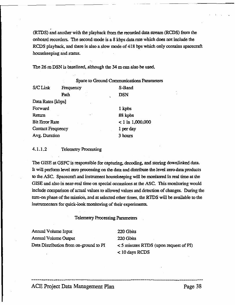
4.1.1.1 Space to Ground Communications
There are three modes of data communication from the spacecraft. The primary mode is at
88 kbps and includes two vinua1 channels, one composed of a real time data stream
---------~----------------------------------------------------------------------------
ACE Project Data Management Plan Page 37
r
(RIDS) and another with the playback from the recorded data stream (RCDS) from the
onboard recorders. The second mode is a 8 kbps data rate which does not include the
RCDS playback, and there is also a slow mode of 418 bps which only contains spacecraft
housekeeping and status.
The 26 m DSN is baseIined, although the 34 m can also be used.
Space to Ground Communications Parameters
S/CLink F~uency S-Band
Path DSN
Data Rates [kbps] Forward
Return
Bit Error Rate
ContactF~uency
Avg. Duration
4.1.1.2 Telemetry Processing
lkpbs
88 kpbs
< 1 in 1.000.000
1 per day
3 hours
The GISE at GSFC is responsible for capturing, decoding. and storing downlinked data.
It will perform level zero processing on the data and distribute the level zero data products
to the ASe. Spacecraft and instrument housekeeping will be monitored in real time at the
GISE and also in near-real time on special occassions at the ASe. This monitoring would
include comparison of actual values to allowed values and detection of changes. During the
tum-on phase of the mission, and at selected other times, the RIDS will be available to the
instrumenters for quick-look monitoring of their experiments.
Telemetry Processing Parameters
Annual Volume Input
Annual Volume Output
Data Distribution from on-ground to PI
220 Gbits
220 Obits
< 5 minutes RIDS (upon ~uest of PI)
< 10 days ReDS
--------------------------------------------------------------------------------------ACE Project Data Management Plan Page 38
> (j tI1
~ a. G 0 """ 0 s s: ~
O'Q
~ a ~I
§
~ O'Q G W \0
INSTRUMENTS
H/K & Science TLM_
....-CMD
• SPACECRAFT
~ Aquisition Data
H/K & Science TLM ...
r
... CMD I
DSN
j~
'. COMMUNICATIONS
J~ j ~-- H/K & Science Telemetry
ory 'r CMD
!
Attitude Telemetry Cont. Replay FDF
~
MOC -.. .. Orbit & Attitude Products
j CMD Requests
Planning r + Interface
Orbit & Attitude Products ... ... ASC Composition Explorer ce Center Science ce Analysis Remote Site Level One Planning Data
Proc. Level Two :e Network Data
d, & Three amics Facility P oc. Data n9 lerations Center ASARs ta Processing Facility
TLM Telemetry
--,
SDPF
RIT on I
Lev PrOI
Level Two~
Proc. , DATA ARCHIVE
I
Data equest
Zero Data
One, Three
Data
!!
~ f:'o '""' I ...... o (11
[ a ~ til til .... g
~
f ...
:.
9 ~ a. ('1:1
g
~ [.
(JQ
8 ~
~
~ ~ ~ o
."3 .". ."5 .,,' .9" IIFIMIAIMI J IIIAI SIQliilj)(jlpIMIAIMI J I JIAISIOlldolllFIMiAIMllI Jj~r~IQINllllllfIMIAIMI JlllAISlolNlol IlEiMIAIMlilJlAI slolNl1l
MAJOR REVIEWS PROJECT"'1 N~ Y' r I II ULLI II' I ~', 1i~I«1¢i,; J , I ~I , 'I ""'H ... I . I j S/W I " .... ,00 I
",OADSD; ; I i 'Mj !: i """",~. I
I ,i ; : I I I i
DOCUMENTATION PROJECT:-tJ'_,:-"-~..t. . 'flit, ~. ; Ii ! I !: 'I 11:11 I! I! i CODESOO:~~I~IIII 111111111 . l' I I I Ii! I III II, I! j :
MO &cDSD I 'I I I I I j I ' , Iw 'lJ~ I I '~jlI ..J.i .... il It ~
MISSION OmRA TlONS ct:N1'Elt (Moe) I I I I I I I I I I I If. • • ' '" ,- . ~ I II'" :q I I "" " ,.;,. •. , . SENSOR DATA PROCCSSINCl PACllITY
·PACORII
• DATA DISTRIBUTION PACn.1TV
FUGIIT DYNAMICS PACILITY (PDf)
ACE SIMULATOR (DYNAMICS A TRAIN'O
FUGIIT OPERATIONS TEAM
OBSERVATORY INTEGR &c 1'p,s'f TRANSPORTABLE I'OCC (ACE 1&1)
• GENERIC TPOCC DEVElOPMENT
• ACIlI&T SYSTEM DBVElOPMENT
SPACOClW'T,QBSilRVA TORY IHTEDIit
MISSION READINESS TEST
ACE SCIENCE CENTER
~
=:11:"::..~c._ A(I.'IIIt.AC1!l_Tl'lM'CI,,, AOSSooA ... UI .... AP.A1_ .......... AT. __ ,.".
1Q ....... ac ... Cl.l1IC.C._A0... ,-. CDIt· ~ 0..,._ .. OCD.~ D.JWt DI·Dt ..... k. 1lIoI •• __ .... _
P.IWI
'JdUo .......
J) ~-
Illmtil~UUilll~nTT~lliTn! III cIT .. nT! ttlIt·""IoI~_. tn.fqlol._._. O$I'C.-s.- ft""Coo., "" . ....., .. .. T ....... _A_ !CP·Ioortf ... .-.._
1.1· ..... ' ......... -U.tndT .. _ ..
u. tnd r-. """'""' .. ar· __ T.-
NAl.Noo-A_ • ..DIlS·OrN_s.c_ OMS .. 0rhiI. l4MItWU $c(twaN
~~J.;:=-.--. PUll .. ..........., Dr",_ 1Ikrit'.-1'Ea.r-~ .... rsa . r-.s.;,_ • QI •• QIoid< .... 1fC. •• _",,-C-_ SDa.s,....o,. __ $lD.s,.. .... __ SI."~ 5, .. ae ..... _ J,nic., n. ... T_ TlUC.T ....... nl~Tc .. lea4!""."
( ... "-~ ... "",,. I .......... · ,m"., _"'111,1"'''') . ... : ..
:l1
i .,.. -N ~ U) ra. g ~ U)
r 5-' o
4.1.2 Mission Control
The OISE at OSFC is responsible for the safe and successful control of the ACE
observatory. The OISE will generate spacecraft and instrument commands for
transmission. perform command checking, schedule DSN contacts, monitor spacecraft
performance, monitor instrument functions, and schedule ground communications and data
transportation. The ASC will direct the science operations through generation of the
science timeline, and clirect the OISE activities on issues related to science data acquisition.
4.1.3 Mission Planning & Scheduling
The mission planning function will be performed in the OISE at OSFC. The ASC will
support the OISE by providing schedules of routine instrument operations, typically
instrument calibration sequences. Mission Planning will be performed in three phases:
long term science planning, short term planning, and timeline preparation. Long term
planning will take the scientistts calibration sequence proposals and establish an
observation outline. Short term planning. performed on a weeldy basis. three weeks in
advance of planned operations. will ref'me the science observation plan and will allow for
specific spacecraft functions required for maintenance of the spacecraft equipment and for
NASA institutional systems availability. Tnnelines will be updated daily. three days in
advance of the planned operations, and will define spacecraft and instrument
configurations, command times, telemetry transmission times, and data recording and
playback operations. Science opemtions are not expected to drive daily timelines since
instrument operations will generally be tttum us on and leave us ontl• No conflicts are
expected.
4.2 Science Operations
The ACE Science Operations will be guided by the ACE Investigator Working Group
(!WO) shich includes the Project Scientist, PI, and Co-Is. The IWG is responsible for the
development of science operations policies, priorities, and objectives. The IWG will also
charter and staff relevant science working groups to support operations, development and
execution.
--------------------------------------------------------------------------------------ACE Project Data Management Plan Page 41
., 4.2.1 Science Control
Mission planing of science opemtions will be performed at the GISE with the support of
the ASC. Command requests will be forwarded (genemlly electronically) from the
instrument facility to the ASC for coordination and conflict resolution. The ASC will then
transmit Integrated Command Flies (ICF) to the GISE. In the event that conflict resolution
does become nescessary, the first step will be contact with the instrument team leaders for
the appropriate instruments and/or the ACE Payload Scientist. Beyond that, thePI and/or
the IWG will be consulted.
The GISE is responsible for monitoring the health and safety of the ACE instruments and
spacecraft. Whenever the RIDS is available, the GISE will conduct alarm processing and
quick-look processing. At special times, to be arranged in advance, alarm processing,
interactive displays, and quick-look processing will be available in real-time at the ASC
and/or a facility adjacent to the Moe.
4.2.2 Science Planning and Scheduling
The infrequent science commands required by instruments can typically be scheduled a
week or more in advance. and will not normally require real time monitoring or response
except at the GISE. Most commands will be low risk and no conflicts are expected so
scheduling is easy and will mostly be left to the individual instrument teams.
--------------------------------------------------------------------------------------ACE Project Data Management Plan Page 42
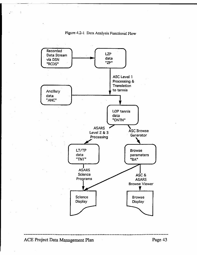
Figure 4.2-1 Data Analysis Functional Flow
Recorded Data Stream via DSN "RCDS"
~
Ancillary data lIANC"
, " LZP ..
data ~
"ZP" "-
ASARS Level 2 & 3 Processing
LT/TP data lITNT"
ASARS Science
Programs
ASC Levell Processing & Translation
if to tennis
11r
LOP tennis data "ONTN"
", , ASC Browse Generator
Browse Viewer
Science Display
Browse Display
--------------------------------------------------------------------------------------ACE Project Data Management Plan Page 43
4.3 Continued Accessibility
The ACE team has waived "proprietary rights" to the data. All appropriate data products
will be properly validated and documented so that they are useful in the public domain, and
delivered in accordance with a detailed schedule of goals which will allow detection of
inadequate compliance. The validation period will be vexy short for some products, such
as the browse parameters, necessitating caveats· in their usage; and substantially longer for
other products such as level three processed data, which are typically validated by
something approaching a peer review process~ Most products will have validation periods
intermediate between these extremes.
The schedule for data delivexy will be used to determine whether the validation process is
being abused to provide an unacceptable proprietary period. It will need frequent updating
since there can be a great number of valid reasons for slow debugging/validation of data
processing. (For example, we may not be able to tum on all of the instruments until we
actually get near Ll, more than 90 days after launch.) A conservative strawman schedule is
provided here, based on an appropriately funded level of effort:
Browse parameter data should be validated in less than 30 days after receipt at the ASC.
with a goal of 7 days (after the initial debugging phase). The browse parameter data will be
available at the ASC via network access.
Level 0 processed data should be validated within no more than 12 months.
Levell processed data should be validated within 18 months at the beginning of the
mission. dropping to within 8 months by the end of the mission.
Many level 2/3 processed data sets should be available within 24 months of launch, with a
goal of delivering most level 2/3 data sets within 12 months by end of mission.
A Guest Investigator (Gl) program has been proposed by the ACE science team which
would include three kinds of GIs, all funded within a more general Space Physics Data
Program:
--------------------------------------------------------------------------------------ACE Project Data Management Plan Page 44
1) Theoretical GIs would have no restrictions on scientific focus* could start immediately
after launch, are expected to not be dependent on leve12/3 processed data, and may or may
not be associated with instrument teams.
2) Associate Investigators would work collaboratively with a specific instrument team at the
host institution, would help develop instrument capability, have joint authorship of papers,
and the instrument team could suggest areas of focus. These investigations could also start
immediately after launch.
3) ExperimentalJPhenomenological Investigations are meant to encourage interdisciplinary!
correlative studies. These would require processed (levels 1, & 2/3) data from one or more
instruments, may use the ASC orremote site facilities, and may or may not associate with
instrument teams. It is expected that some areas of investigation would be off-limits to
these GIs (e.g. prime objectives, thesis topics, etc~) and that these positions would start
about 2 years after launch.
The ACE team is particularly interested in encouraging investigations in which the GI
works closely with one or more of the instrument teams. Although the team will develop a
system that can be readily used by outside investigators~ it is also true that most of the
instruments are sufficiently complex that a considerable investment of time would be
required to understand the detailed data. Because of this, the most productive Guest
Investigations will be those that combine the experience developed within the instrument
teams with the enthusiasm and new ideas of outside investigators.
In the unlikely event that the ACE Science Team is requested to assist an unassoclated user
to develop a parallel data analysis effort (for example, to help an unassociated user to
generate his own higher level products from the public domain level 0 data), priority will be
given to the normal Team validation process in the case of limited time and resources.
--------------------------------------------------------------------------------------ACE Project Data Management Plan Page 45
4.3.1 Data Repositories
4.3.1.1 Project Data Repositories
The GISE will archive raw data for two years and LZP data for 30 days. The ASC will
archive all data created by the team including level zero, one, two, and three processed
data. Since the transfer of data to the ASARS will be via 4 mm tape, each ASARS will also
have a permanent version of their data.
4.3.1.2 Discipline Archives
It is expected that the ASC will be able to set up as a Space Physics Data System node.
This will allow the space physics discipline to access all ACE science data, as well as any
ancilliary information.
4.3.1.3 NSSDC
The NSSDC is base1ined as the final repository for all ACE processed (Level 2/3) data and
the browse data set. The format and transfer process are TBD. The volume of data per
year will be about 200 Gbyte.
4.3.2 Directories and Catalogs
The ACE Science Center will provide, via network access, browse parameter files which
will contain SllIl1ITl3lY data from each instrument and can be used to select events and time
periods of particular interest such as flares, shock passages. etc. It will include time
averages of magnetic field v~ors, averaged count rates from each of CRIS, SIS, ULEIS,
SEPICA, SWIMS, SWICS, and EP AM, and proton density, temperature, solar wind
speed, and bi-streaming electron indicators from SWEP AM. It will also include
housekeeping and status parameters from all instruments and the spacecraf4 attitude and
spin angle. etc. Time resolution will range roughly from 1 to 5 minutes. and the data
volume will be roughly 11 megabytes per week.
One aspect of this data set will be a catalog of data files, so that event times can be easily
translated into data file name. The housekeeping and other parameters stored in the browse
files will also be useful for trend monitoring.
------------------------------------------------------------------~-------------------
ACE Project Data Management Plan Page 46
.r
In the browse parameter fil~ CRIS, SIS, and SEPlCA will provide count rate versus time
with five-minute time resolution for about 40 of the most interestiDg rates. This will also'
provide nuclear charge versus time with a time resolution of about one second. ULEIS and
EP AM will provide count rate versus time for 40 more rates, but with a time resolution of
about 1 minute. SWIMS and SWICS provisions to the browse file are TBD. The MAG
instrument will provide average magnetic field in an inertial co-ordinate system with
approximately 1 minute time resolution. Indicators of fluctuations in the field and the
power spectra of those fluctuations will be provided with the same time resolution.
4.3.3 Standards
The data will be in compliance with documented standards which include at least minimaI
operating system independence, substantial self documentation, and tools for data
manipulation. The baseline is that the data will be available in both HDF and the Tennis
formats, as appropriate.
4.3.4 Scientific Computing Resources
The ACE project will use the NASA computing resources of the GISE only to a level
consistent with the performance of its payload operations and monitoring duties. The
primary scientific computing resources used will be the workstations at the ASe and the
ASARS. At this time, there is no pIan to provide non-project researchers with substantial
computer resources, although the ACE Science Center is investigating how much additional
resources would be needed to make the ASC a node of the Space Physics Data System, if
that system develops in time.
4.3.5 Networking Requirements
The ASe and all ASARS plan to support both TCP/IP and DECnet protocols for network
communications. It is expected that both NASA Science Internet (NSI) and NSIISP AN
will be used for network connections.
--------------------------------------------------------------------------------------ACE Project Data Management Plan Page 47
,
5.0 Products
It is expected that all data products will be permanently stored at the ASe. The data products will include all levels of unprocessed and processed data (Levels 0, 1, and 2/3)
and the browse data set, as well as spacecraft housekeeping and orbit/attitude data.
Because inclusion of analysis software and any calibration data and tables is implicit in the
Tennis data storage format, these will also be included in the archive. CmTent NASA
policy calls for the use of the NSSDC as a final archive.
5.1 Science Data Product Summary
Although the general content of the processed data sets (level 2/3 processed data) from the
instruments is known, the specifics of the data products that will actually be archived is
TBD. As per tennis standards, analysis software and internal documentation will be
included with the individual data sets archived at Caltech, as well as any test and calibration
information that is required. HDF is the baseline for the data products which will be
archived at the NSSDC, but the specifics of content and media are TBD.
6.0 Special Considerations
No special considerations for the ACE mission have been identified at this time.
--------------------------------------------------------------------------------------ACE Project Data Management Plan Page 48
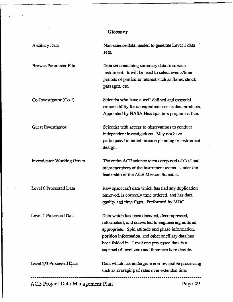
· '
Ancillary Data
Browse Parameter Flle
Co-Investigator (Co-I)
Guest Investigator
Investigator Working Group
Level 0 Processed Data
Levell Processed Data
Level 2/3 Processed Data
Glossary
Non-science data needed to generate Levell data
sets.
Data set containing snmmary data from each
instrument. It will be used to select events/time
periods of particular interest such as flares, shock
passages, etc.
Scientist who have a well-defined and essential
responsibility for an experiment or its data products.
Appointed by NASA Headquarters program office.
Scientist with access to observations to conduct
independent investigations. May not have
participated in initial mission planning or instrument
design.
The entire ACE science team composed of Co-I and
other members of the instrument teams. Under the
leadership of the ACE Mission Scientist.
Raw spacecraft data which has had any duplication
removed, is correctly time ordered, and has data
quality and time flags. Performed by MOC.
Data which has been decoded, decompressed,
reformatted, and converted to engineering units as
appropriate. Spin attitude and phase information,
position information, and other ancillary data has
been folded in. Level one processed data is a
superset of level zero and therefore is re-doable.
Data which has undergone non-reversible processing
such as averaging of rates over extended time
ACE Project Data Management Plan Page 49
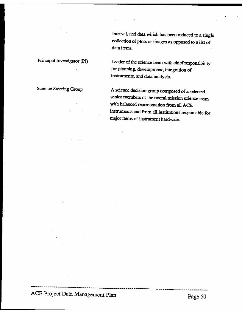
Principal Investigator (PI)
Science Steering Group
interval, and data which has been reduced to a single
collection of plots or iinages as opposed to a list of data items.
Leader of the science team with chief responsibility
for planning, development, integration of
instruments, and data analysis.
A science decision group composed of a selected -
senior members of the overa! mission science team
with balanced representation from all ACE
instruments and from all institutions responsible for
major items of instrument hardware.
--------------------------------------------------------------------------------------ACE Project Data Management Plan Page 50
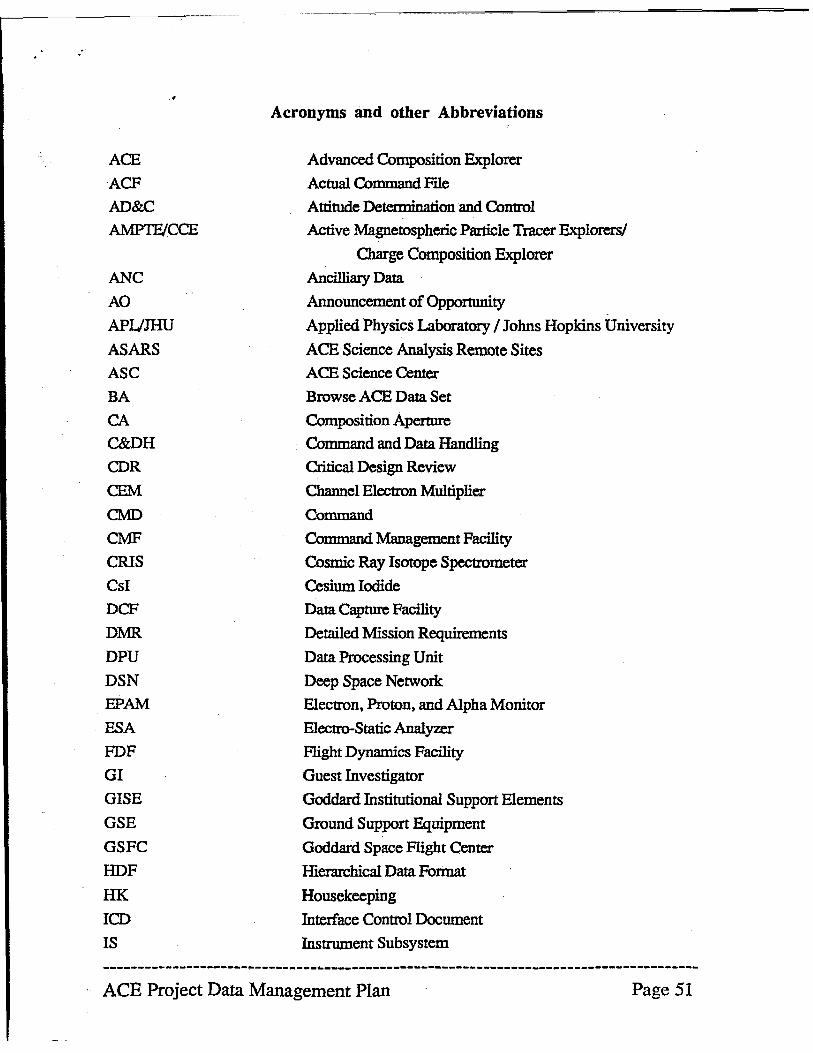
ACE
ACF
AD&C
AMPTFJCCE
ANC
AO
APUJHU
ASARS
ASC
BA
CA
C&DH
CDR
CEM
CMD
CMF
CRIS
CsI
DCF
DIvm.
DPU
DSN EPAM
ESA
PDF GJ
GISE
GSE
GSFC
HDF HK ICD
IS
Acronyms and other Abbreviations
Advanced Composition Explorer
Actual Command FIle
Attitude Detenninati.on and Control
Active Magnetospheric Particle Tracer Explorers!
Charge Composition Explorer
AncilliaIy Data
Announcement of Opportunity
Applied Physics Laboratory / Johns Hopkins University
ACE Science Analysis Remote Sites ACE Science Center
Browse ACE Data Set
Composition Aperture
Command and Data Handling
Critical Design Review
Channel Electron Multiplier
Command
Command Management Facility
Cosmic Ray Isotope Spectrometer
Cesium Iodide
Data Capture Facility
Detailed Mission Requirements
Data Processing Unit
Deep Space Network
Electron, Proton, and Alpha Monitor
Electro-Static Analyzer
Flight Dynamics Facility
Guest Investigator
Goddard Institutional Support Elements
Ground Support Equipment
Goddard Space Flight Center
Hierarchical Data Fonnat
Housekeeping
Interface Control Document
Instrument Subsystem
--------------------------------------------------------------------------------------ACE Project Data Management Plan Page 51
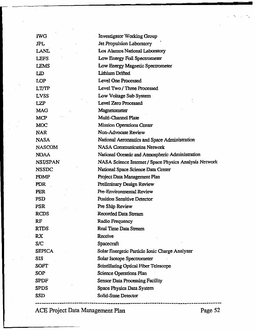
IWG
JPL
LANL
LEFS
!EMS un LOP LT{I'P
LVSS
LZP
MAG
MCP
MOC
NAR
NASA
NASCOM
NOAA
NSI/SPAN
NSSDC
PDMP
PDR
PER
PSD
PSR
RCDS
RF
RIDS
RX
SIC SEPlCA
SIS
SOFf
SOP
SPDF
SPDS
SSD
Investigator Working Group
J~~pw~on~
Los Alamos National ~
Low Energy Foil Spectrometer
Low Energy Magnetic Spectrometer
Lithium Drifted
Level One Processed
Level Two I Three Processed
Low Voltage Sub System
Level Zero Processed
Magnetometer
Multi-Channel Plate
Mission Operations Center
Non-Advocate Review
National Aeronautics and Space Administration
NASA Communicatins Network
National Oceanic and Atmospheric Administration
NASA Science Internet I Space Physics Analysis Network
National Space Science Data Center
Project Data Management Plan
Preliminary De~gn Review
Pre-Environmental Review
Position Sensitive Detector
Pre Ship Review
Reconied Data Stream
Radio Frequency
Real Time Data Stream
Receive
Spacecraft
Solar Energetic Particle Ionic Charge Analyzer
Solar Isotope Spectrometer
Scintillating Optical Fiber Telescope
Science Operations Plan
Sensor Data Processing Facility
Space Physics Data System
Solid-State Detector
--------------------------------------------------------------------------------------ACE Project Data Management Plan Page 52
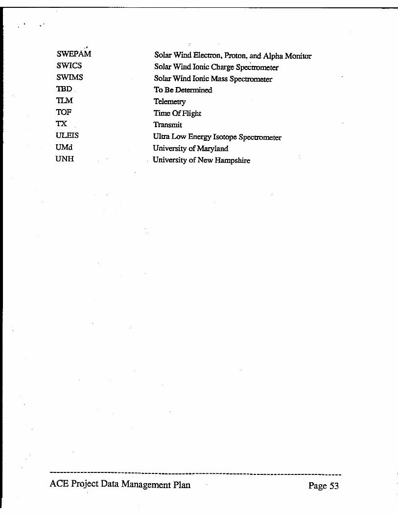
SWEPAM
SWICS
SWIMS
TBD
11M TOF
TX
ULEIS
UMd
UNH
Solar Wind Electron. Proton, and Alpha Monitor
Solar Wind Ionic Charge SpeCtrometer
Solar Wmd Ionic Mass Spectrometer
To Be Determined
Telemetry
Time Of Flight
Transmit
Ultra Low Energy Isotope Spectrometer
University of Maryland
University of New Hampshire
--------------------------------------------------------------------------------------ACE Project Data Management Plan Page 53
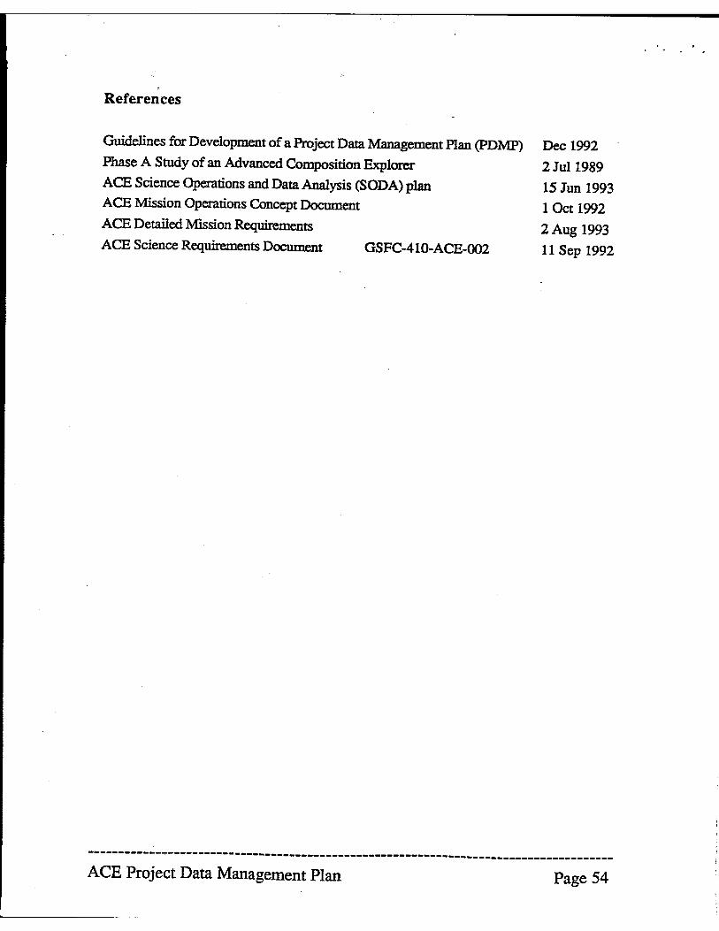
References
Guidelines for Development of a Project Data Management PIan (pDMP)
Phase A Smdy of an Advanced Composition Explorer
ACE Science Operations and Data Analysis (SODA) plan
ACE Mission Operations Concept Document
ACE Detailed Mission Requirements
ACE Science Requirements Document GSFC-410-ACE-002
Dec 1992
2Jul1989
15 Jun 1993
1 Oct 1992
2 Aug 1993
11 Sep 1992
--------------------------------------------------------------------------------------ACE Project Data Management Plan Page 54
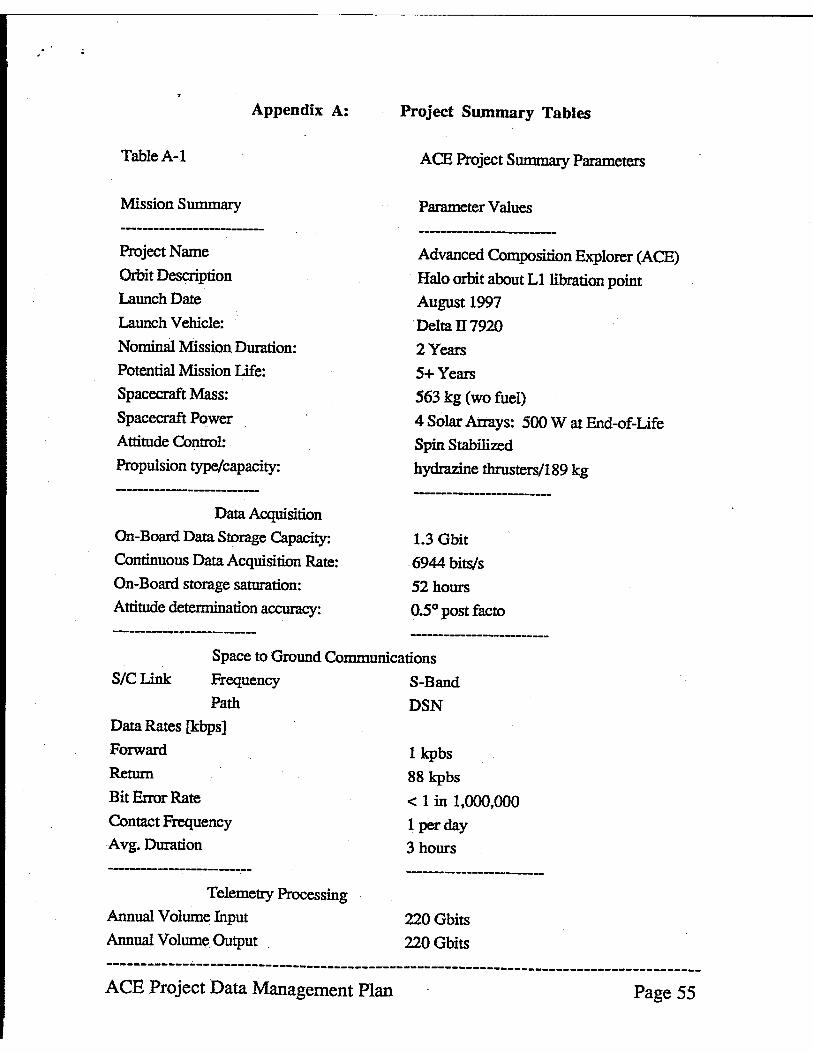
Table A-I
Mission Summary
Project Name
Orbit Description
Launch Date
Launch Vehicle:
Appendix A:
Nominal Mission Duration:
Potential Mission Life:
Spacecraft Mass:
Spacecraft Power
Attitude Control:
Propulsion type/capacity:
Data Acquisition
On-Board Data Storage Capacity:
Continuous Data Acquisition Rate:
On-Board storage saturation:
Attitude determination accuracy:
Project Summary Tables
ACE Project Summary Parameters
Parameter Values
Advanced Composition Explorer (ACE)
Halo orbit about Lllibration point
August 1997
. Delta n 7920
2 Years
5+ Years
563 kg (wo fuel)
4 Solar Arrays: 500 W at End-of-Life
Spin Stabilized
hydrazine thrusters/189 kg
-------------------------
1.3 Gbit
6944 bits/s
52 hours
0.50 post facto
Space to Ground Communications
SIC Link Frequency S-Band
Path DSN Data Rates [kbps]
Forward
Return
Bit Error Rate
Contact Frequency
Avg. Duration
Telemetry Processing
Annual Volume Input
Annual Volume Output
1 kpbs
88 kpbs
< 1 in 1,000,000
1 per day
3 hours
-------------------------
220 Obits
220 Obits
--------------------------------------------------------------------------------------ACE Project Data Management Plan Page 55
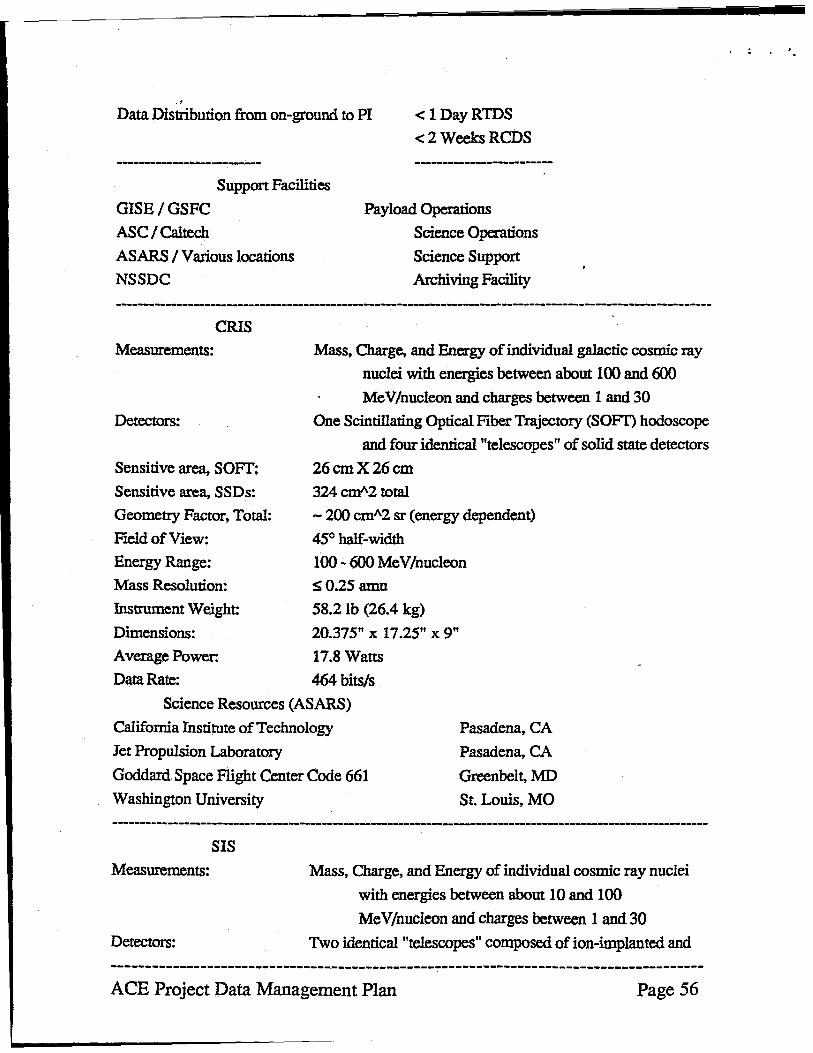
· . Data Distribution from on-ground to PI < 1 DayRTDS
< 2 Weeks RCDS
Support Facilities
GISE/GSFC Payload Operations
Science Operations
Science Support
Archiving Facility
ASC I Ca1tech ASARS I Various locations
NSSDC
CRIS
Measurements:
Detectors:
Sensitive area, SOFf:
Sensitive are~ SSDs:
Geometry Factor, Total;
Field of View:
Energy Range:
Mass Resolution:
Instrument Weight:
Dimensions:
Average Power:
Data Rate:
Mass. Charge. and Energy of individual galactic cosmic ray
nuclei with energies between about 100 and 600 MeV/nucleon and charges between 1 and 30
One Scintillating Optical Fiber Trajectory (SOFIj hodoscope
and four identical "telescopes" of solid state detectors
26 cmX26cm 324 cm'2 total
- 200 cmA2 sr (energy dependent)
45° half-width
100.;. 600 MeV/nucleon
S0.25 amu
58.2 Ib (26.4 kg)
20.375" x 17.25" x 9"
17.8 Watts
464 bits/s Science Resources (ASARS)
California Institute of Technology
Jet Propulsion Laboratory
Pasadena, CA
Pasadena, CA
Greenbelt, MD
St. Louis, MO
Goddard Space Flight Center Code 661
Washington University
---------------------------------------------------------------------------------.--------------------------SIS
Measurements:
Detectors:
Mass. Charge, and Energy of individual cosmic ray nuclei
with energies between about 10 and 100
Me V/nucleon and charges between 1 and 30 Two identical "telescopes" composed of ion-implanted and
--------------------------------------------------------------------------------------ACE Project Data Management Plan Page 56
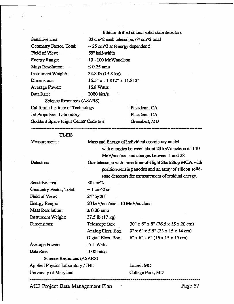
Sensitive area
Geometry Factor, Total:
Field of View:
Energy Range:
Mass Resolution:
Instrument Weight:
Dimensions:
Average Power:
Data Rate:
lithium-drifted silicon solid-state detectors
32 cm"2 each telescope, 64 em"2 total
- 25 cm"2 sr (energy dependent)
55° half-width
10 - 100 MeV/nucleon
SO.25 amu
34.8 lb (15.8 kg)
16.5" x 11.812" x. 11.812"
16.8 Watts
2000 bits/s
Science Resources (ASARS)
California Institute of Technology
Jet Propulsion Laboratory
Pasadena, CA
Pasadena, CA
Greenbelt, MD Goddard Space Flight Center Code 661
ULEIS
Measurements:
Detectors:
Sensitive area
Geometry Factor, Total:
Field of View:
Energy Range:
Mass Resolution:
Instrument Weight:
Dimensions:
Average Power:
Data Rate:
Mass and Energy of individual cosmic ray nuclei
with energies between about 20 keY/nucleon and 10
MeV/nucleon and charges between 1 and 28
One telescope with three time-of-flight Start/Stop MCPs with
position-sensing anodes and an array of silicon solid
state detectors for measurement of residual energy.
80cm"2
-1 cm"2 sr
24° by 20°
2OkeV/nucleon -10MeV/nucleon
~O.30amu
37.51b (17 kg)
Telescope Box
Analog Elect. Box.
Digital Elect. Box.
17.1 Watts
l000bits/s
30" x 6" X 8" (76.5 x 15 x 20 cm)
9" x 6" x 5.5" (23 x 15 x 14 cm)
6" x 6" x 6" (15 x 15 x 15 em)
Science Resources (ASARS)
Applied Physics Laboratory / JHU
University of Maryland
LaureI,MD
College Park, MD
--------------------------------------------------------------------------------------ACE Project Data Management Plan Page 57
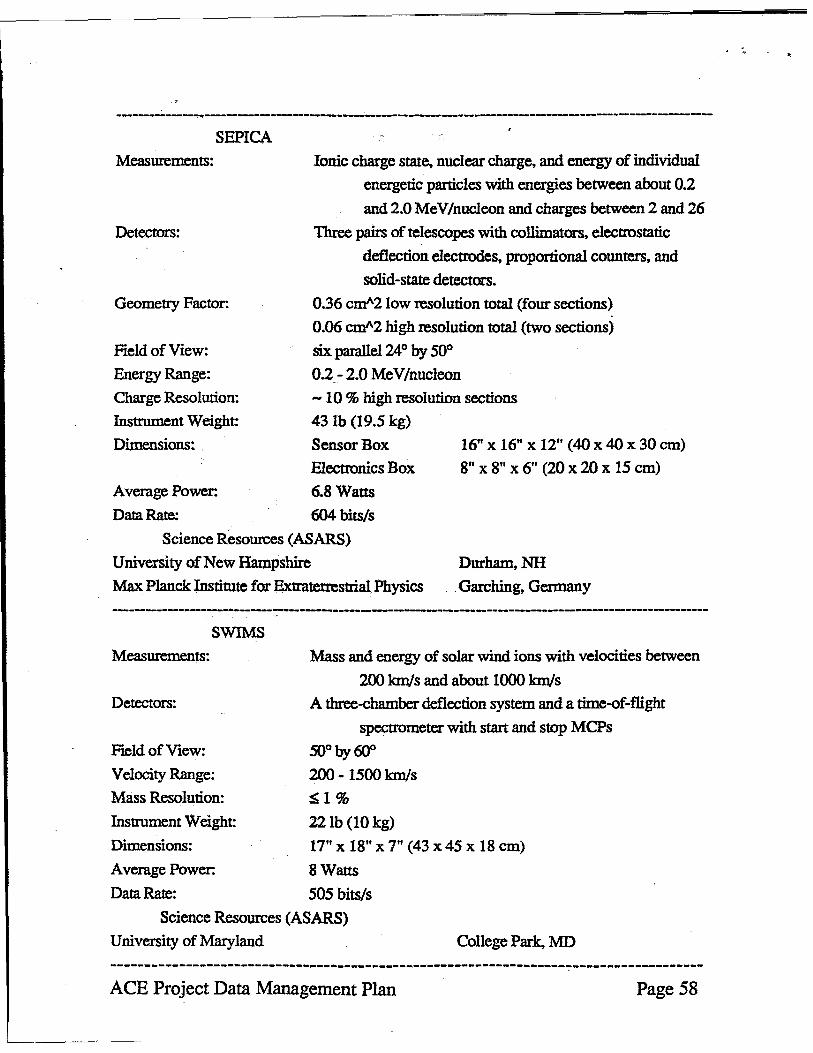
--------------------------------------------------------------SEPICA
Measmements:
Detectors:
Geometry Factor:
Field of View:
Energy Range:
Charge Resolution:
Instrument Weight:
Dimensions:
Average Power:
Data Rate:
Ionic charge state, nuclear charge, and energy of individual
energetic particles with energies between about 0.2
and 2.0 MeV/nucleon and charges between 2 and 26
Three pairs of telescopes with collimators, electrostatic
deflection electrodes, proportional counters, and
solid-state detectors.
0.36 eml\2 low resolution total (four sections)
0.06 cm"2 high resolution total (two sections)
six parallel 24° by 50° 0.2 - 2.0 MeV/nucleon
- 10 % high resolution sections
43 lb (19.5 kg)
Sensor Box
Electronics Box
6.8 Watts
604 bits/s
16" X 16" x 12" (40 x 40 x 30 em)
8" x 8" x 6" (20 x20 x 15 em)
Science Resources (ASARS)
University of New Hampshire Dur~NH
Garching, Germany Max Planck Institute for Extraterrestrial Physics
SWIMS
Measmements: Mass and energy of solar wind ions with velocities between
200 km/s and about 1000 km/s
Detectors: A three-chamber deflection system and a time-of-fIight
Field of View:
Velocity Range:
Mass Resolution:
Instrument Weight:
Dimensions:
Average Power:
Data Rate:
spectrometer with start and stop MCPs
50° by 60°
200 - 1500 km/s
SI%
22lb (10 kg)
17" x 18" x 7" (43 x 45 x 18 em)
8Wans
505 bits/s Science Resources (ASARS)
University of Maryland College Park, MD
ACE Project Data Management Plan Page S8
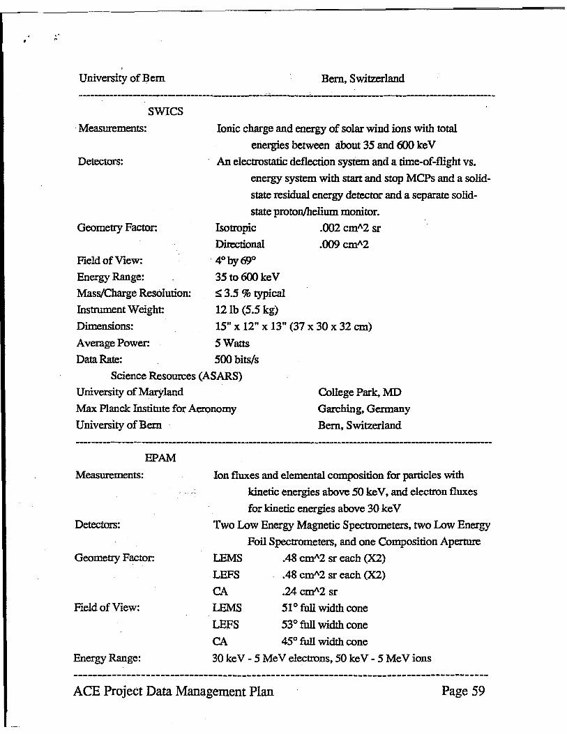
University of Bern Bern, Switzerland
------------------------------------------------~----------~----------------------------------------------SWICS
Measurements:
Detectors:
Geometry Factor:
Field of View:
Energy Range:
Mass/Charge Resolution:
Instrument Weight:
Dimensions:
Average Power:
Data Rate:
Ionic charge and energy of solar wind ions with total
energies between about 35 and 600 ke V
An electrostatic deflection system and a time-of-flight vs.
energy system with start and stop MCPs and a solld
state residual energy detector and a separate solid
state proton/helium monitor.
Isotropic .002 cm"2 sr
Directional
4° by 690
35 to 600keV
S 3.5 % typical
12lb (5.5 kg)
15" x 12" x 13" (37 x 30 x 32 em)
5 Watts
500 bits/s
Science Resources (ASARS)
University of Maryland College Park, MD
Garching, Germany
Bern, Switzerland
Max Planck Institute for Aeronomy
University ofBem
EPAM
Measurements:
Detectors:
Geometry Factor:
Field of View:
Energy Range:
Ion fluxes and elemental composition for particles with
kinetic energies above 50 keY, and electron fluxes
for kinetic energies above 30 ke V
Two Low Energy Magnetic Spectrometers, two Low Energy
Foil Spectrometers, and one Composition Aperture
LEMS .48 cm"2 sr each (X2)
LEFS
CA
LEMS LEFS
.48 cm"2 sr each (X2)
.24 em"2 sr
51 ° full width cone
53° full width cone
CA 45° full width cone
30 ke V - 5 Me V electrons, 50 ke V - 5 MeV ions
ACE Project Data Management Plan Page 59
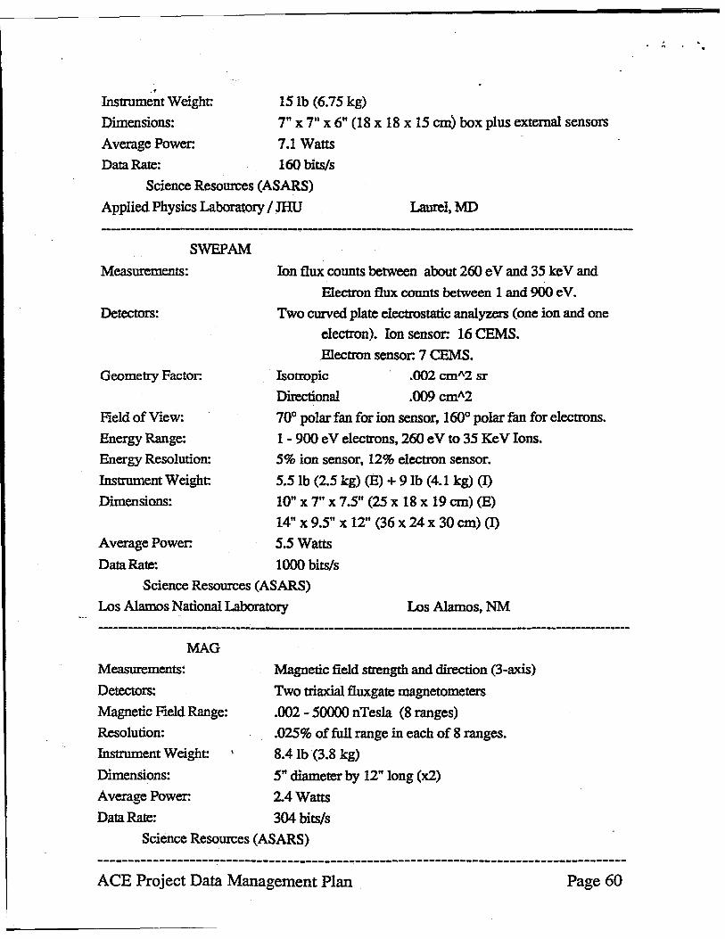
., Instrument Weight:
Dimensions:
Average Power:
Data Rate:
15 lb (6.75 kg)
7" x 7" X 6" (18 x 18 x 15 em) box plus external sensors
7.1 Watts
160 bits/s
Science Resources (ASARS)
Applied Physics Laboratory / JHU Laurel,MD
SWEPAM
Measurements:
Detectors:
Geometry Factor:
Field of View:
Energy Range:
Energy Resolution:
Instrument Weight:
Dimensions:
Average Power:
Data Rate:
Ion flux counts between -about 260 e V and 35 ke V and
Electron flux counts between 1 and 900 eVa
Two curved plate electrostatic analyzers (one ion and one
electron). Ion sensor: 16 CEMS.
Electron sensor. 7 CEMS.
Isotropic
Directional
.002 cm"2 sr
.OO9cmA2
70° polar fan for ion sensor, 160° polar fan for electrons.
1 - 900 eV electrons, 260 eV to 35 KeV Ions.
5% ion sensor, 12% electron sensor.
5.5 lb (2.5 kg) (E) + 9lb (4.1 kg) (I)
10" X 7" X 7.5" (25 x 18 x 19 cm) (E)
14" x 9.5" x 12" (36 x 24 x 30 em) (I)
5.5 Watts
1000 bits/s
Science Resources (ASARS)
Los Alamos National Laboratory Los Alamos. NM
MAG
Measurements:
Detectors:
Magnetic Field Range:
Resolution:
Instrument Weight:
Dimensions:
Average Power:
Data Rate:
Magnetic field strength and direction (3-axis)
Two triaxial fluxgate magnetometers
.002 - 50000 nTesla (8 ranges)
.025% of full range in each of 8 ranges.
8.41b (3.8 kg)
5" diameter by 12" long (x2)
2.4 Watts
304 bits/s
Science Resources (ASARS)
-------------------------_._------------------------------------------------------------ACE Project Data Management Plan Page 60
"
Bartol Research Institute, U. of Delaware
Goddard Space Flight Center, Code 690
Newark, DE
Greenbelt, MD
------------------------------------------------------------------------------------------------------------
--------------------------------------------------------------------------------------ACE Project Data Management Plan Page 61
Recommended