Embed Size (px)
Citation preview

ZZ-OPTBK rev B
1
ZZPerformance.com ”Option B” Dual-Pass IC Reservoir upgrade
Tools you will need:
Flat head screw driver
Trim removal tool (H.E. install only, not required)
10mm socket
6mm socket
5/8” spark plug socket and 6” extension
Torx T50
Torx T30
Drill Bit ( Size “R” or 11/32” ONLY )
1/8”-27 NPT Tap and Tap Handel
Pipe Putty or Teflon Tape
6mm Hex bit socket (ball end preferred)
E7 inverted socket (dual pass install only)
Rubber mallet (dual pass only)
When working on your car it is always a good idea to disconnect your battery. This will prevent bumping certain terminals and wires
and blowing fuses or worse.

ZZ-OPTBK rev B
2
Step 1 : Removing the supercharger:
First the supercharger belt must be removed, use a flat headed screw driver to pop the cap off the factory tensioner pulley. Then
use a T50 Torx bit and turn counter clock wise until the factory tensioner is maxed out, slide the belt off of one of the pulleys, then
release the tensioner slowly.
If your car is equipped with the plastic fuel rail cover, you will need to remove the 2 T30 bolts and it will easily pull off. Now use the
6mm hex to remove the (4) supercharger bolts. A ball style hex bit socket would work the best. Unplug/remove the following:
Brake booster line(pull up on the white clip, then it will slide right off), SC inlet pressure sensor, lower boost bypass vacuum line,
intake tube from throttlebody, throttlebody plug, EVAP plastic line, and the T fill((2) 10mm bolts on the inlet of the blower). Remove
the blower by tilting and turning it to get it out from under the radiator hose. Now swap the SC pulley using a press or supercharger
(specific) pulley puller that will support the entire side of the pulley, a 3 or 4 jaw puller will NOT WORK, it will damage the pulley and
possibly even the SC shaft. Then reinstall the ZZP modular hub so that the largest OD is outward and perfectly flush with the end of
the snout shaft and press in the Christmas tree plug in the end of the snout shaft.

ZZ-OPTBK rev B
3
Step 2: Removing the fuel Rail
This will require a 10mm socket to remove the (2) fuel rail bolts and the single bolt for the fuel rail feed line. The coolant line will not
need to me disconnected from the head, this will avoid the chance of losing the coolant copper sealing washers and/or stripping the
threads in the head for the banjo bolt. Remove the fuel rail by tilting/twisting/wiggling out from under the coolant line. Next
remove the (4) injector clips, injectors themselves, and injector cups from the heads. Inspect the injector cup o-rings for damage or
excessive wear, and grease up the o-rings on the injector cups and the injectors themselves.
Step 3 : Removing the lower intake to install the dual pass endplate:
Now that you can access the bottom of the lower intake, remove the 1 horizontal lower manifold bolt at the very bottom of the S/C.
Using a 15mm socket with a 3” extension or a 15mm deep well socket. Image below shows the manifold (Left) and the Bracket with
bolt (red line) you are removing show on the right .
ZZ-OPTBK rev B
4
Now it is time to remove the 5 intake bolts, and 2 nuts using a 10mm socket. It makes it a lot easier to remove the intake by also
removing the studs using an E7 socket. Then remove the 10mm bolt that holds the dipstick onto the lower intake. Unplug the MAP
sensor and drain the coolant from the IC system by disconnecting the hoses from the factory endplate. Make sure to have a drain
pan under the car, this can be messy. Disconnect both IC hoses, and remove intake from engine bay.
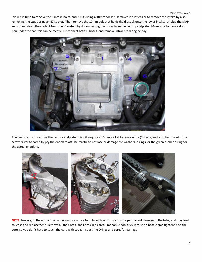
The next step is to remove the factory endplate; this will require a 10mm socket to remove the (7) bolts, and a rubber mallet or flat
screw driver to carefully pry the endplate off. Be careful to not lose or damage the washers, o-rings, or the green rubber o-ring for
the actual endplate.
NOTE: Never grip the end of the Laminova core with a hard faced tool. This can cause permanent damage to the tube, and may lead
to leaks and replacement. Remove all the Cores, and Cores in a careful manor. A cool trick is to use a hose clamp tightened on the
core, so you don’t have to touch the core with tools. Inspect the Orings and cores for damage
ZZ-OPTBK rev B
5
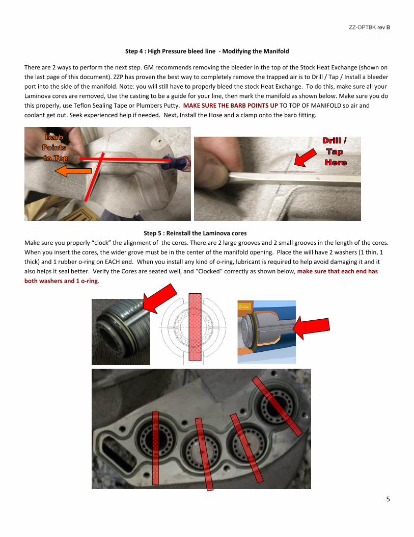
Step 4 : High Pressure bleed line - Modifying the Manifold
There are 2 ways to perform the next step. GM recommends removing the bleeder in the top of the Stock Heat Exchange (shown on
the last page of this document). ZZP has proven the best way to completely remove the trapped air is to Drill / Tap / Install a bleeder
port into the side of the manifold. Note: you will still have to properly bleed the stock Heat Exchange. To do this, make sure all your
Laminova cores are removed, Use the casting to be a guide for your line, then mark the manifold as shown below. Make sure you do
this properly, use Teflon Sealing Tape or Plumbers Putty. MAKE SURE THE BARB POINTS UP TO TOP OF MANIFOLD so air and
coolant get out. Seek experienced help if needed. Next, Install the Hose and a clamp onto the barb fitting.
Step 5 : Reinstall the Laminova cores
Make sure you properly “clock” the alignment of the cores. There are 2 large grooves and 2 small grooves in the length of the cores.
When you insert the cores, the wider grove must be in the center of the manifold opening. Place the will have 2 washers (1 thin, 1
thick) and 1 rubber o-ring on EACH end. When you install any kind of o-ring, lubricant is required to help avoid damaging it and it
also helps it seal better. Verify the Cores are seated well, and “Clocked” correctly as shown below, make sure that each end has
both washers and 1 o-ring.
ZZ-OPTBK rev B
6
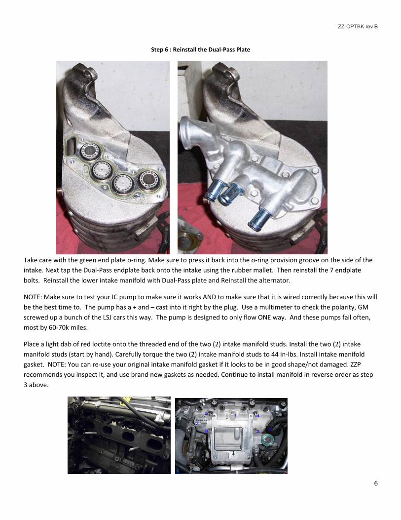
Step 6 : Reinstall the Dual-Pass Plate
Take care with the green end plate o-ring. Make sure to press it back into the o-ring provision groove on the side of the
intake. Next tap the Dual-Pass endplate back onto the intake using the rubber mallet. Then reinstall the 7 endplate
bolts. Reinstall the lower intake manifold with Dual-Pass plate and Reinstall the alternator.
NOTE: Make sure to test your IC pump to make sure it works AND to make sure that it is wired correctly because this will
be the best time to. The pump has a + and – cast into it right by the plug. Use a multimeter to check the polarity, GM
screwed up a bunch of the LSJ cars this way. The pump is designed to only flow ONE way. And these pumps fail often,
most by 60-70k miles.
Place a light dab of red loctite onto the threaded end of the two (2) intake manifold studs. Install the two (2) intake
manifold studs (start by hand). Carefully torque the two (2) intake manifold studs to 44 in-lbs. Install intake manifold
gasket. NOTE: You can re-use your original intake manifold gasket if it looks to be in good shape/not damaged. ZZP
recommends you inspect it, and use brand new gaskets as needed. Continue to install manifold in reverse order as step
3 above.

ZZ-OPTBK rev B
7
Step 5: ReInstalling the fuel Rail :
Reverse of Step 2; First reinstall the injector cups in the head, then install the new or cleaned fuel injectors in the fuel rail, reinstall
injector clips, and finally reinstall the fuel rail. Reinstall the 3 bolts for the fuel rail.
Step 6 : Dual Pass Hoses:
Now that you have 2 hoses and 3 fittings you will need to modify your factory IC hoses. Remove the old upper IC hose from coolant
filler “sight glass” and attach it to the middle fitting on the dual pass endplate, no modifications are needed. Make sure to use
hose clamps for every connection moving forward (clamps not shown below) Now take the old lower IC hose and cut it
(about 4.25”) so that when you attach one of the plastic Ts included in the Dual pass install kit, it is a straight shot to the UPPER dual
pass fitting. Now that you have a piece of IC hose left you will cut that to length (about 3.5”) so that it attaches to the top fitting of
the dual pass and the other end perfectly connects to the T that you just added, see pic below. (pics below is of the removed from
the engine so it is easier to see the IC hoses) Make sure to use hose clamps for every connection (clamps not shown
below). Ziptie to secure the T-Fitting to the bracket that was from the “sight glass” filler.
Note all the hoses and routing below. The direction of the water flows from the pump to the I.C. manifold and H.E. does
matter, and it is very critical when you add the Option B kit. You but you must make sure pump works in the proper
direction (Into the center and out the side).

ZZ-OPTBK rev B
8

ZZ-OPTBK rev B
9
Step 7 : Surge tank and hoses
Attach the bracket Item #: ZZ-OPTBBRKT ( Cobalt only - Sold seperatly ) to the Surge tank. There is a Bolt and nut that gets installed on
the tank tab, and a bolt with self-tapping threads that gets screwed to the bottom of the tank. Next install the tank and bracket to
the car with M6 Nylock nuts as shown below.
Route the small clear hose from the barb on the manifold as shown below ( or the Stock Heat Exchange location) large tank hose
under the radiator core support behind the headlight, and secure with zip-ties to the body. Make sure it does not rub on the S/C
pulley or any sharp metal edges. Make sure no kinks are in hose. Note: The small hose is routed into the washer bottle cap loop.
Make sure to use hose clamps for every connection. Tighten all clamps, all Hardware, and reinstall all components. This should complete the install of the Dual-Pass Kit. Thanks for your continued support and enjoy your ZZPerformance power enhancements!

ZZ-OPTBK rev B
10
GM Service Manual Diagram for Hose Barb fitting valve placement.