Embed Size (px)
Citation preview
ZylinderkopfdichtungenAdvanced MLS-Technology – Leistungsfähigkeit in jeder Lage
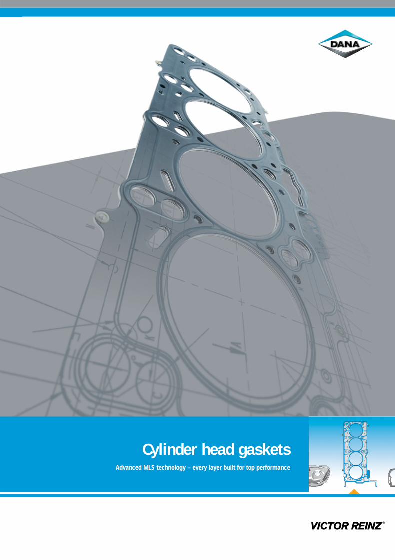
Cylinder head gasketsAdvanced MLS technology – every layer built for top performance
Treat it rough, make it tough:
While your customer enjoys a fast
drive, the head gasket is working
extra hard. It’s good to know it’s
made by VICTOR REINZ.
Contents
3 Sealing Products - VICTOR REINZ
4 Systematic quality
5 Development services
12 MLS technology
16 Materials
18 Coatings
20 Beads
22 Stoppers
30 Special solutions
32 Three-land junction
34 Survey of MLS designs
36 MLS designs for gasoline engines
38 MLS designs for diesel engines
40 Concepts for the future
42 Product range
43 The Dana network
¬ 2
¬ 3
For more than 50 years, VICTOR REINZhas been an established name amongthe world’s top automobile manufactu-rers by providing top-quality products.Reliable products and on-time deliveryare as much a part of VICTOR REINZ asour innovative design and systemscompetence. At VICTOR REINZ, goodideas continue to evolve, and our headgaskets continue to improve. This spiritof innovation enables us to find newways to permanently upgrade the per-formance of our head gaskets – and,in turn, your engine. We will continueto meet the demands of engine buildersnow and into the future.
Beyond our competitorsAt VICTOR REINZ, we understand thedemands placed on the sealing oftoday's cylinder heads – and we’vedeveloped the solution. We call itAdvanced MLS1) technology. But we don’t stop there. We also utilize the most advanced equipment, themost rigorous testing standards, FEA2)
compliant hardware and software,expert knowledge, and long years ofexperience to provide products thattruly stand out in the marketplace.And perhaps most importantly, everyemployee at VICTOR REINZ is trulycommitted to serving our customers.So when you choose VICTOR REINZ,you’ll benefit from even more than themost advanced gaskets – you’ll alsoreceive consulting, development, pro-duction, logistics, and service compe-tence at the highest level.
Performance defined
¬ Recognized for providing the world’smost innovative gasket solutions
¬ Top-quality products and highprocess reliability
¬ Holistic systems competence¬ Uniform, worldwide access to
consulting, development,production, logistics, and servicingat the highest level through neworganizational structure
Better ideas. Manufactured by VICTOR REINZ.
ALWAYS A STEP AHEAD
MLS1) = Multi-layer steel
FEA2) = Finite element analysis
Sealing Products – VICTOR REINZ:A global presenceIn 2003, the Dana Corporation consoli-dated and reorganized its five gasket,shielding system and valve cover systemfacilities into a central, clearly defineddivision: Sealing Products - VICTORREINZ. As a world leader in gasket pro-duction we now provide service andsupport from 19 locations in Europe,North America, South America andJapan. You'll find us in every importantautomotive manufacturing hub, provi-ding the most innovative system solu-tions in the world.
¬ 4
Every business aims to perform fasterand better. But this is especially impor-tant in the fast-evolving automotivesector.
How can we do it so quickly?Time and again, our customers aresurprised by the short lead times atVICTOR REINZ. We do this by employ-ing all the necessary experts in-house,from development to series production.Our design system is also compatiblewith your in-house CAD system, whe-ther it’s CATIA, ProEngineer, IDEAS, orUnigraphics. In addition, we can alsoperform all the important validationtests on-site with our own equipment.By having all our resources in-house,we can greatly reduce handling times.As a result, based solely on the engine'sspecifications, we can deliver headgaskets directly to your assembly line,ready for installation.
Smart combinationsAligning conventional developmenttools with one other can result in sig-nificant time savings.
One example: At VICTOR REINZ we notonly test the head gaskets with FEAcomputer programs – we also use mod-ern prototyping procedures to buildfunctional models at a very early stage.When testing the specific sealing func-tions, for instance, the prototypes supplyextremely valuable data. This processenables us to determine in advancewhether a head gasket’s performanceis maximized, so that individual func-tions don’t require optimization later.
Quality from the startSome 70 percent of an automobile'scomponents come from external sup-pliers. This means the quality of avehicle depends greatly on the qualityof the supplied products. And becausequality cannot be improved later, weunderstand that intelligent productdesign, exact planning, and compatibleengineering from the start will ensurequality assurance in product develop-ment and manufacturing.
Partners with the bestVICTOR REINZ’s know-how has beenappreciated by the European automo-tive industry for decades. From theMCC Smart to the Maybach V12 engineto the high-tech head gaskets for For-mula One racing engines, VICTOR REINZsupplies complete gasket systems.
Our aim is to continue partnering withthe best, by providing top-quality pro-ducts and service. See our referencelist at www.reinz.com for details.
Always faster, always better – from the initial concept to series production
STREAMLINED PRODUCTION CYCLES
The quality system: the high standard of our quality management system is reflected in the many certificates and prizes awarded by our customers – we are also pleased that the environmentprofits from our work, as a number of environmental compatibility certificates prove.
Nissan: NX 96,Next 21 Recogni-tion Award
Volvo Cars Awardof Excellence
Spirit ofInnovation
DIN EN ISO14001
Steinbeis-Initiative»Customersevaluatesuppliers«
DanaLeadershipAward
ISO/TS 16949: Including DIN EN ISO 9001, VDA 6.1 and EAQF94 as well as specific customer requirements from GM,DaimlerChrysler, and all German auto makers.
¬ 5
Logistics
Testing
Series productionrelease
Calculation
Prototyping
Design & construction
Manufacturing
»Built-in«understanding
Assessment ofrequirements
Design that’s right the first time
Design that’s right the first time
STEPS TO OPTIMUM PRODUCT DESIGN
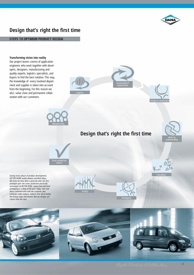
Transforming vision into reality Our project teams consist of applicationengineers who work together with devel-opers, designers, manufacturing andquality experts, logistics specialists, andbuyers to find the best solution. This way,the knowledge of every involved depart-ment and supplier is taken into accountfrom the beginning. For this reason wealso value close and permanent collab-oration with our customers.
During every phase of product development,VICTOR REINZ avoids detours and blind alleys.We know we have done a good job when the firstprototype goes into series production practicallyunchanged. At VICTOR REINZ, repeat trial-and-errorprototyping is a thing of the past. Today, clear anddirect communication with the customer, pluscomputer-aided analysis, reduces time spent duringthe testing stage and ensures that our designs arecorrect from the start.
¬ 6
Assessment ofrequirements: Theearlier the better
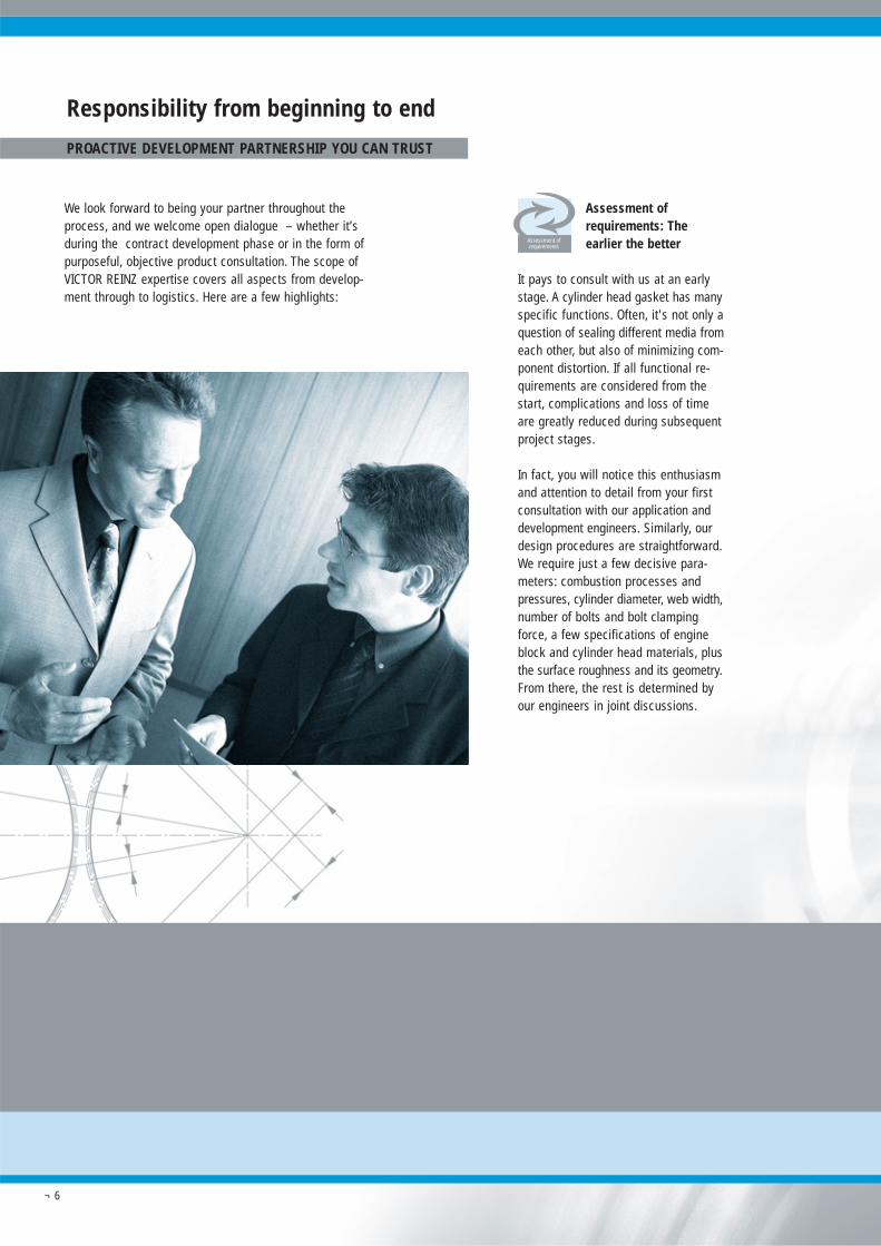
It pays to consult with us at an earlystage. A cylinder head gasket has manyspecific functions. Often, it's not only aquestion of sealing different media fromeach other, but also of minimizing com-ponent distortion. If all functional re-quirements are considered from thestart, complications and loss of timeare greatly reduced during subsequentproject stages.
In fact, you will notice this enthusiasmand attention to detail from your firstconsultation with our application anddevelopment engineers. Similarly, ourdesign procedures are straightforward.We require just a few decisive para-meters: combustion processes andpressures, cylinder diameter, web width,number of bolts and bolt clampingforce, a few specifications of engineblock and cylinder head materials, plusthe surface roughness and its geometry.From there, the rest is determined byour engineers in joint discussions.
Responsibility from beginning to end
PROACTIVE DEVELOPMENT PARTNERSHIP YOU CAN TRUST
Assessment ofrequirements
We look forward to being your partner throughout theprocess, and we welcome open dialogue – whether it’sduring the contract development phase or in the form ofpurposeful, objective product consultation. The scope ofVICTOR REINZ expertise covers all aspects from develop-ment through to logistics. Here are a few highlights:
¬ 7
Finite element analysis(FEA): Working smarterfrom the start
A great amount of the developmenttime – and therefore costs – requiredin the past can now be saved by meansof component simulations in computers,i.e. simulated tests using virtual models.By the same token, practical experi-ence positively influences the FEA pro-grams at VICTOR REINZ. This continu-ous refinement of our computing modelsand simulations mean that our programsget smarter over time. The result: Allrelevant functional parts and criticalareas of the entire composite structureof engine block, head gasket andcylinder head are examined in detailduring the FEA calculations in the designphase, leading to optimum gasket de-velopment.
The first step during FEA involves ana-lyzing the clamped status of the entireengine block, including head, cylinderhead gasket and head bolts. After un-clamping the structure, which corre-sponds to a setting of the components,a realistic simulation is carried out,taking temperatures and ignition pres-sures into account. Similarly, all non-linearities are considered, especiallythe resilience characteristics of thebeads.
Calculation
VICTOR REINZ developmental engineersthink and work in conjunction with ourcustomers' development departments.This leads to the high efficiency thatgives our customers a leading edge,and permits our products to be adaptedquickly to changing conditions.
Prototyping: Equal to thefinal product
We also differ from other suppliers byproviding close-to-production toolingfrom the start. After the sheets havebeen coated on series production equip-ment, and the gasket contour has beencut with lasers, the beads of the headgasket are stamped with our embossingtools. These tools are produced on ourpremises quickly and cost-effectively.Your advantage: Prototypes are of thesame quality as the later series gaskets– with few deviations. Modern CNC-con-trolled measurement equipment ensuresoptimum quality monitoring. Subse-quently, all relevant data are recordedin a technical document.
Prototyping
Design and construction:Built to fit
Obviously, engines are not built up a-round the cylinder head gasket. In prac-tice, the opposite is true. Attention toproduct design combined with high-quality materials is the basis for func-tional, reliable, high-quality head gas-kets.Thinking beyond our competitors is astandard procedure at VICTOR REINZ:During the design phase, for example,we visualize the assembly sequence inthe production line, and during repairwork, we consider the packaging as-pects. We also consider recycling issuesand clean separation of the materialsused.
Interfaces: »Built-in«understanding
Cylinder head gaskets from VICTORREINZ not only fit into the engines, butalso into the 3D computer-design worldsof our customers. We speak the samelanguage as your designers, and supplythe geometric data of the required headgasket in the specified data format,using the fastest available online datatransmission methods.
Design & construction
»Built-in«understanding
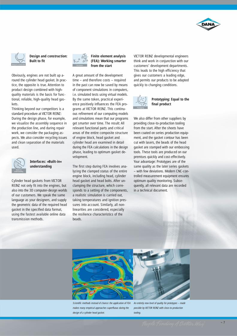
Scientific methods instead of chance: the application of FEA
makes many empirical approaches superfluous during the
design of a cylinder head gasket.
An entirely new level of quality for prototypes – made
possible by VICTOR REINZ with close-to-production
tooling.
¬ 8
Testing: Tougher than practical use
Apart from using modern engine testmethods, we also carry out extensivetests in our chemical and physical la-boratories. As a customer, you choosebetween numerous testing and simu-lation possibilities, and you determinethe testing scope and budget with us.This ensures that you receive optimumvalue during the testing phase.
In addition, through Dana Sealing Pro-ducts and its five development centersin Neu-Ulm, North America, Japan, andBrazil, VICTOR REINZ has worldwideaccess to 27 engine test stands andassociated laboratories for analysisand static/dynamic pre-testing. All ac-tivities are coordinated by the Compe-tence Center R & D.
Testing
Laboratory tests (excerpt)¬ RPM 550 3): By means of a pressure-
sensitive film (Fuji film), the distri-bution of surface pressure over thehead gasket is determined, scanned,and evaluated electronically.
¬ RPM 528 3): By means of resonancepulsers and simulators, various con-ditions (temperature, pressure, sealinggap movement) are simulated, andconclusions drawn about the headgasket's endurance life.
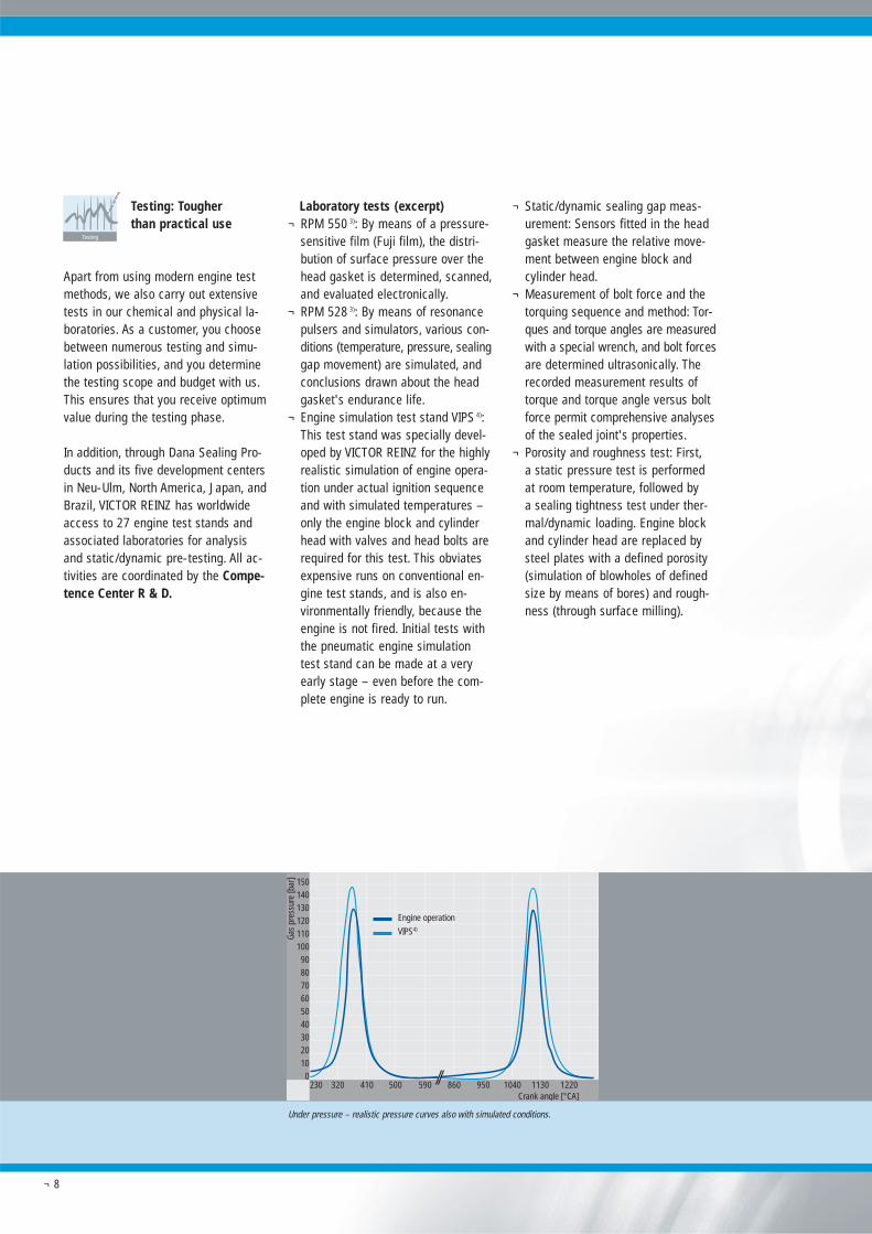
¬ Engine simulation test stand VIPS 4):This test stand was specially devel-oped by VICTOR REINZ for the highlyrealistic simulation of engine opera-tion under actual ignition sequenceand with simulated temperatures –only the engine block and cylinderhead with valves and head bolts arerequired for this test. This obviatesexpensive runs on conventional en-gine test stands, and is also en-vironmentally friendly, because theengine is not fired. Initial tests withthe pneumatic engine simulationtest stand can be made at a veryearly stage – even before the com-plete engine is ready to run.
¬ Static/dynamic sealing gap meas-urement: Sensors fitted in the headgasket measure the relative move-ment between engine block andcylinder head.
¬ Measurement of bolt force and thetorquing sequence and method: Tor-ques and torque angles are measuredwith a special wrench, and bolt forcesare determined ultrasonically. Therecorded measurement results oftorque and torque angle versus boltforce permit comprehensive analysesof the sealed joint's properties.
¬ Porosity and roughness test: First,a static pressure test is performedat room temperature, followed by a sealing tightness test under ther-mal/dynamic loading. Engine blockand cylinder head are replaced bysteel plates with a defined porosity(simulation of blowholes of definedsize by means of bores) and rough-ness (through surface milling).
Engine operation
VIPS4)
Gas
pres
sure
[bar
] 1501401301201101009080706050403020100
230 320 410 500 590 860 950 1040 1130 1220Crank angle [°CA]
Under pressure – realistic pressure curves also with simulated conditions.
¬ 9
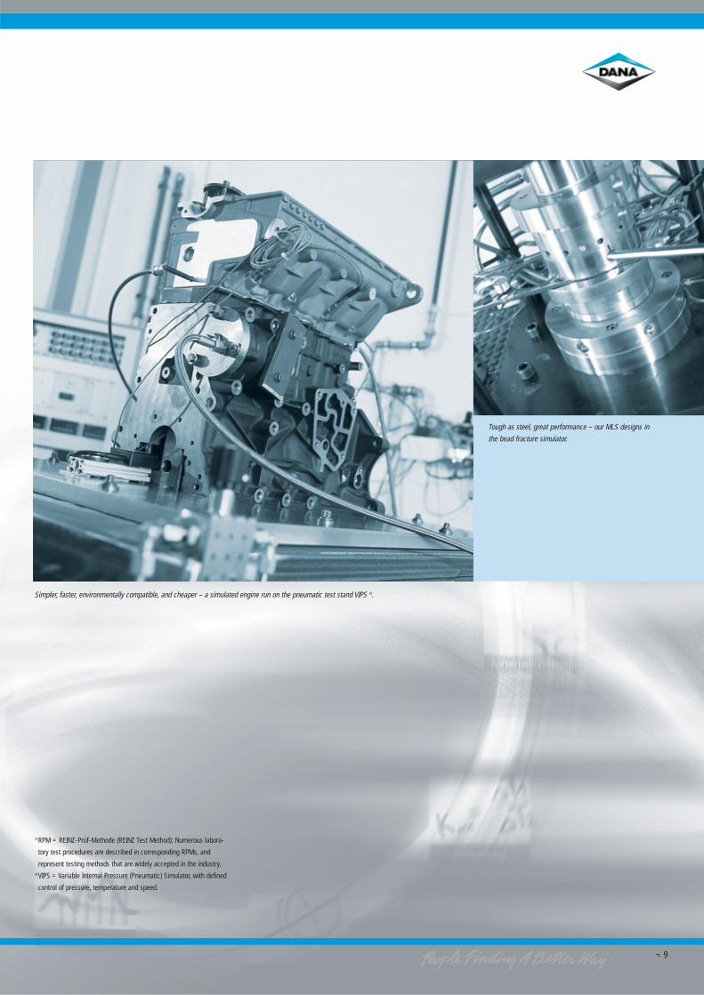
Simpler, faster, environmentally compatible, and cheaper – a simulated engine run on the pneumatic test stand VIPS 4).
Tough as steel, great performance – our MLS designs in
the bead fracture simulator.
3) RPM = REINZ-Prüf-Methode (REINZ Test Method): Numerous labora-
tory test procedures are described in corresponding RPMs, and
represent testing methods that are widely accepted in the industry.4) VIPS = Variable Internal Pressure (Pneumatic) Simulator, with defined
control of pressure, temperature and speed.
¬ 10
Engine test standsThe examinations conducted on enginetest stands range from straightforwardendurance tests to low-temperaturethermal shock tests with freely selec-table temperatures, loads, and speedgradients.¬ Nitrogen pressure test: Before and
during engine operation, the individ-ual combustion chambers are subjec-ted to internal pressures up to 120bar using nitrogen. Functionality andsealing potential of the cylinder headgasket is evaluated by monitoring theadjacent combustion chambers andthe surrounding coolant channels.
¬ Electronic distortion and roughnessmeasurements on the deck surfacesof engine block and cylinder head,before and after the engine is run.
¬ Measuring the change in bolt force:
Using ultrasonics, the preload of headbolts can be determined before, dur-ing, and after an engine run.
¬ Analysis and evaluation of adjoiningcomponents: Frictional damage,scoring, bead measurement, and sur-face pressure distribution after theengine test run.
Documentation¬ All test results are summarized and
explained in a comprehensive testreport. This simplifies and speeds upsubsequent fine-tuning with your en-gine designers and builders.
Quality assurance:Beyond the standards
At VICTOR REINZ, we have a name forour quality assurance process – system-atic quality. This process providesintelligent quality management for ra-tional zero-error production for produc-tion reliability and efficiency beyondthe current standards. During the tes-ting phase, we simulate the manufac-turing process by using close-to-seriestooling. This enables us to test cylinderhead gaskets in close to their finalstate without delay, complete with adetailed test report and quality certif-icates for all the materials used, asrequired for sample approval. Subse-quently, we can immediately begin pre-series and series production.
Series productionrelease
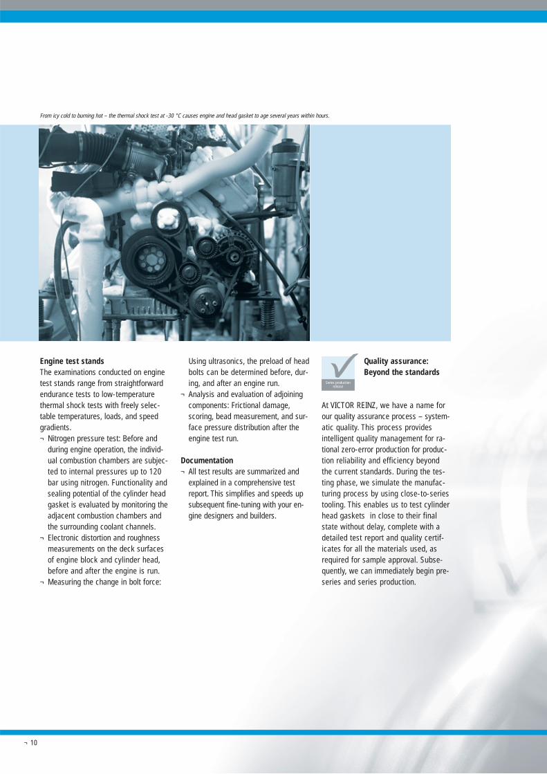
From icy cold to burning hot – the thermal shock test at -30 °C causes engine and head gasket to age several years within hours.
¬ 11
VICTOR REINZ has already been certi-fied in accordance with the latest (2002)issue of ISO/TS 16949, which is ac-cepted by all automobile manufacturersworldwide. Moreover, our EnvironmentalManagement System complies withDIN EN ISO 14001 for the use of envi-ronmentally compatible technologies.Obviously, these standards and officialcertificates have high practical signifi-cance, but equally important is our in-ternal approach to ensuring productquality and environmental awareness.Rest assured that our employees aretruly committed to maintaining thestrong relationships and high level ofconfidence we’ve developed over theyears with our customers – it’s some-thing that can’t be measured, but whichwe continually provide.
Manufacturing: Efficientand cost-effective
Flexible, fast, and cost-effective manu-facturing are made possible at VICTORREINZ by utilizing the most modern tech-nologies in our production lines andclusters. The head gasket's final pro-perties are influenced decisively andspecifically by the individual processingstages and their sequence.
Manufacturing
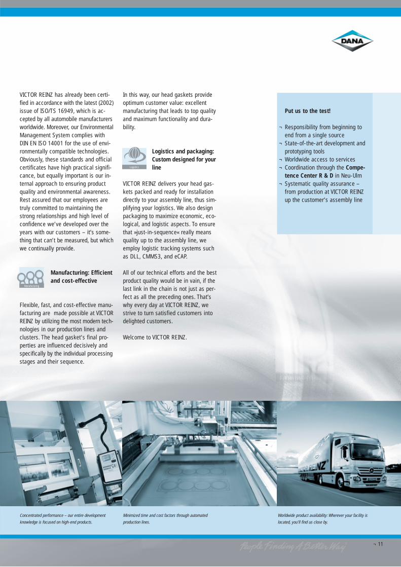
Concentrated performance – our entire development
knowledge is focused on high-end products.
Minimized time and cost factors through automated
production lines.
Worldwide product availability: Wherever your facility is
located, you'll find us close by.
In this way, our head gaskets provideoptimum customer value: excellentmanufacturing that leads to top qualityand maximum functionality and dura-bility.
Logistics and packaging:Custom designed for yourline
VICTOR REINZ delivers your head gas-kets packed and ready for installationdirectly to your assembly line, thus sim-plifying your logistics. We also designpackaging to maximize economic, eco-logical, and logistic aspects. To ensurethat »just-in-sequence« really meansquality up to the assembly line, weemploy logistic tracking systems suchas DLL, CMMS3, and eCAP.
All of our technical efforts and the bestproduct quality would be in vain, if thelast link in the chain is not just as per-fect as all the preceding ones. That’swhy every day at VICTOR REINZ, westrive to turn satisfied customers intodelighted customers.
Welcome to VICTOR REINZ.
Logistics
Put us to the test!
¬ Responsibility from beginning toend from a single source
¬ State-of-the-art development andprototyping tools
¬ Worldwide access to services¬ Coordination through the Compe-
tence Center R & D in Neu-Ulm¬ Systematic quality assurance –
from production at VICTOR REINZup the customer's assembly line
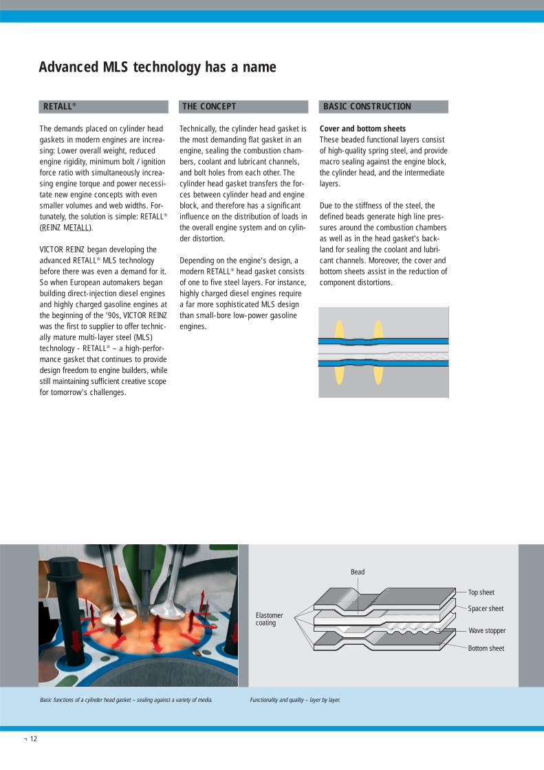
Basic functions of a cylinder head gasket – sealing against a variety of media. Functionality and quality – layer by layer.
Bead
Spacer sheet
Wave stopper
Bottom sheet
Top sheet
Elastomercoating
¬ 12
RETALL®
The demands placed on cylinder headgaskets in modern engines are increa-sing: Lower overall weight, reducedengine rigidity, minimum bolt / ignitionforce ratio with simultaneously increa-sing engine torque and power necessi-tate new engine concepts with evensmaller volumes and web widths. For-tunately, the solution is simple: RETALL®
(REINZ METALL).
VICTOR REINZ began developing theadvanced RETALL® MLS technologybefore there was even a demand for it.So when European automakers beganbuilding direct-injection diesel enginesand highly charged gasoline engines atthe beginning of the '90s, VICTOR REINZwas the first to supplier to offer technic-ally mature multi-layer steel (MLS)technology - RETALL® – a high-perfor-mance gasket that continues to providedesign freedom to engine builders, whilestill maintaining sufficient creative scopefor tomorrow's challenges.
THE CONCEPT
Technically, the cylinder head gasket isthe most demanding flat gasket in anengine, sealing the combustion cham-bers, coolant and lubricant channels,and bolt holes from each other. Thecylinder head gasket transfers the for-ces between cylinder head and engineblock, and therefore has a significantinfluence on the distribution of loads inthe overall engine system and on cylin-der distortion.
Depending on the engine's design, amodern RETALL® head gasket consistsof one to five steel layers. For instance,highly charged diesel engines requirea far more sophisticated MLS designthan small-bore low-power gasolineengines.
Advanced MLS technology has a name
BASIC CONSTRUCTION
Cover and bottom sheetsThese beaded functional layers consistof high-quality spring steel, and providemacro sealing against the engine block,the cylinder head, and the intermediatelayers.
Due to the stiffness of the steel, thedefined beads generate high line pres-sures around the combustion chambersas well as in the head gasket's back-land for sealing the coolant and lubri-cant channels. Moreover, the cover andbottom sheets assist in the reduction ofcomponent distortions.
¬ 13
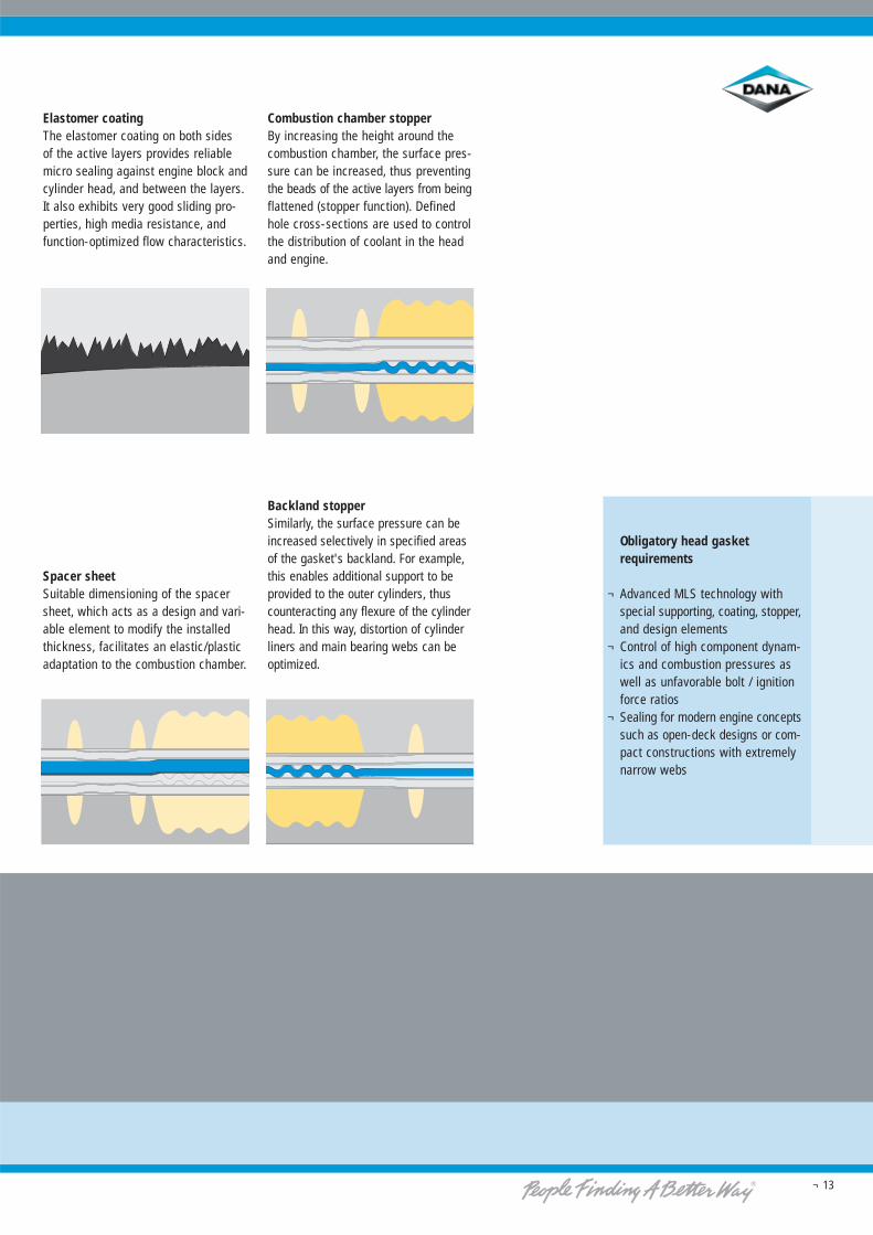
Elastomer coatingThe elastomer coating on both sides of the active layers provides reliablemicro sealing against engine block andcylinder head, and between the layers.It also exhibits very good sliding pro-perties, high media resistance, andfunction-optimized flow characteristics.
Spacer sheetSuitable dimensioning of the spacersheet, which acts as a design and vari-able element to modify the installedthickness, facilitates an elastic/plasticadaptation to the combustion chamber.
Combustion chamber stopperBy increasing the height around thecombustion chamber, the surface pres-sure can be increased, thus preventingthe beads of the active layers from beingflattened (stopper function). Definedhole cross-sections are used to controlthe distribution of coolant in the headand engine.
Backland stopperSimilarly, the surface pressure can beincreased selectively in specified areasof the gasket's backland. For example,this enables additional support to beprovided to the outer cylinders, thuscounteracting any flexure of the cylinderhead. In this way, distortion of cylinderliners and main bearing webs can beoptimized.
Obligatory head gasketrequirements
¬ Advanced MLS technology withspecial supporting, coating, stopper,and design elements
¬ Control of high component dynam-ics and combustion pressures aswell as unfavorable bolt / ignitionforce ratios
¬ Sealing for modern engine conceptssuch as open-deck designs or com-pact constructions with extremelynarrow webs
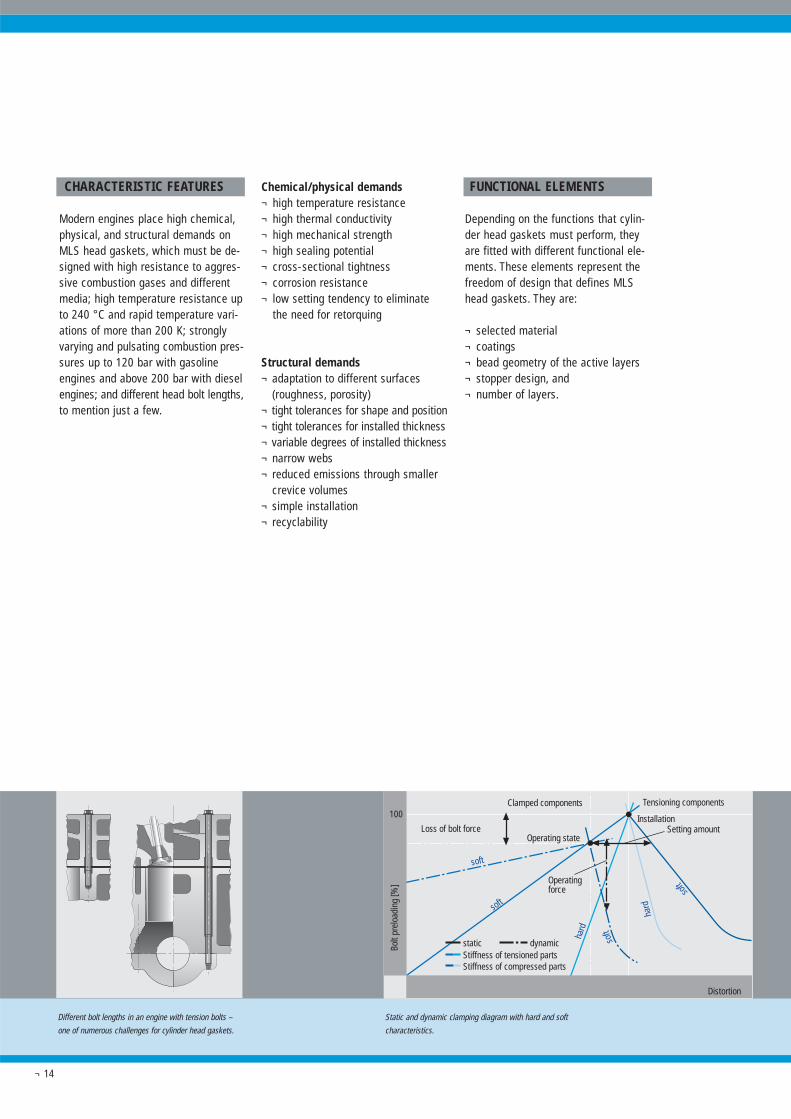
Static and dynamic clamping diagram with hard and soft
characteristics.
Different bolt lengths in an engine with tension bolts –
one of numerous challenges for cylinder head gaskets.
Tensioning componentsClamped components
Operatingforce
soft
soft
hard
Setting amountInstallation
Operating stateLoss of bolt force
Stiffness of compressed partsStiffness of tensioned partsstatic dynamic so
ft
soft
hard
Distortion
100
Bolt
prel
oadi
ng [%
]
¬ 14
CHARACTERISTIC FEATURES
Modern engines place high chemical,physical, and structural demands onMLS head gaskets, which must be de-signed with high resistance to aggres-sive combustion gases and differentmedia; high temperature resistance upto 240 °C and rapid temperature vari-ations of more than 200 K; stronglyvarying and pulsating combustion pres-sures up to 120 bar with gasolineengines and above 200 bar with dieselengines; and different head bolt lengths,to mention just a few.
Chemical/physical demands¬ high temperature resistance¬ high thermal conductivity¬ high mechanical strength¬ high sealing potential¬ cross-sectional tightness¬ corrosion resistance¬ low setting tendency to eliminate
the need for retorquing
Structural demands¬ adaptation to different surfaces
(roughness, porosity)¬ tight tolerances for shape and position¬ tight tolerances for installed thickness¬ variable degrees of installed thickness¬ narrow webs¬ reduced emissions through smaller
crevice volumes¬ simple installation¬ recyclability
FUNCTIONAL ELEMENTS
Depending on the functions that cylin-der head gaskets must perform, theyare fitted with different functional ele-ments. These elements represent thefreedom of design that defines MLShead gaskets. They are:
¬ selected material¬ coatings¬ bead geometry of the active layers¬ stopper design, and¬ number of layers.
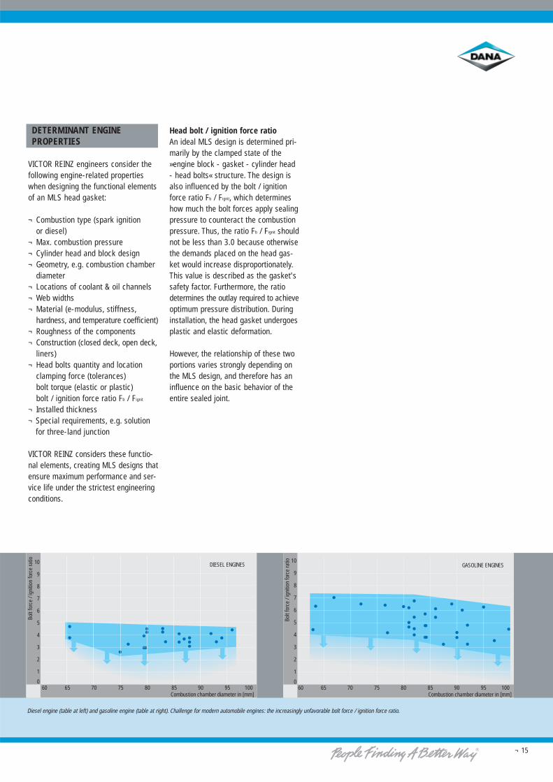
Diesel engine (table at left) and gasoline engine (table at right). Challenge for modern automobile engines: the increasingly unfavorable bolt force / ignition force ratio.
10
9
8
7
6
5
4
3
2
1
0
Bolt
forc
e / i
gniti
on fo
rce
ratio
Combustion chamber diameter in [mm]60 65 70 75 80 85 90 95 100
DIESEL ENGINES10
9
8
7
6
5
4
3
2
1
0
Bolt
forc
e / i
gniti
on fo
rce
ratio
Combustion chamber diameter in [mm]60 65 70 75 80 85 90 95 100
GASOLINE ENGINES
¬ 15
DETERMINANT ENGINEPROPERTIES
VICTOR REINZ engineers consider thefollowing engine-related propertieswhen designing the functional elementsof an MLS head gasket:
¬ Combustion type (spark ignition or diesel)
¬ Max. combustion pressure¬ Cylinder head and block design¬ Geometry, e.g. combustion chamber
diameter¬ Locations of coolant & oil channels¬ Web widths¬ Material (e-modulus, stiffness,
hardness, and temperature coefficient)¬ Roughness of the components¬ Construction (closed deck, open deck,
liners)¬ Head bolts quantity and location
clamping force (tolerances)bolt torque (elastic or plastic)bolt / ignition force ratio Fb / Fignit
¬ Installed thickness¬ Special requirements, e.g. solution
for three-land junction
VICTOR REINZ considers these functio-nal elements, creating MLS designs thatensure maximum performance and ser-vice life under the strictest engineeringconditions.
Head bolt / ignition force ratioAn ideal MLS design is determined pri-marily by the clamped state of the»engine block - gasket - cylinder head- head bolts« structure. The design isalso influenced by the bolt / ignitionforce ratio Fb / Fignit, which determineshow much the bolt forces apply sealingpressure to counteract the combustionpressure. Thus, the ratio Fb / Fignit shouldnot be less than 3.0 because otherwisethe demands placed on the head gas-ket would increase disproportionately.This value is described as the gasket'ssafety factor. Furthermore, the ratiodetermines the outlay required to achieveoptimum pressure distribution. Duringinstallation, the head gasket undergoesplastic and elastic deformation.
However, the relationship of these twoportions varies strongly depending onthe MLS design, and therefore has aninfluence on the basic behavior of theentire sealed joint.

¬ 16
TESTED QUALITY
The outstanding functional propertiesand top performance of MLS head gas-kets from VICTOR REINZ are not onlydue to the innovative design and expe-rience in manufacturing, but also be-cause of precise material selection. Allmaterials (and their delivery conditions)for our head gaskets are specified pre-cisely in our proprietary REINZ Stand-ards. We utilize a wide selection of sheetmetals with different properties andcoatings to provide maximum flexibilityin terms of performance, durability, andprice.
SHEET METAL PROPERTIES
Top sheet and bottom sheetHigh quality, springy stainless steelsare used exclusively for the active layersof the gasket. Cover and bottom sheetsmust be able to follow the movementsof the sealing gap. Even after the beadshave been embossed, the employedspring steels must retain very good re-silient properties, high tensile strength,and optimum corrosion resistance.
Conventional stoppersFor conventional stoppers, we utlize a selection of steel ranging from fromhigh-carbon steel to stainless steel, de-pending on the required stopper design.
Wave and trapezoidal stoppersFor stoppers with wave or trapezoidaldesign, only spring steels are used.
Spacer sheetSpacer sheets have the widest range of design options. Because the spacersheet can perform either as a functio-nal layer or as a thickness-determininglayer, different types of steel are usedranging from stainless steel to carbonsteel with various hardnesses andthicknesses. To protect carbon steelfrom corrosion, they can be eitheraluminium plated or zinc galvanized.
Materials that make sense
Best quality – layer for layer
¬ 17
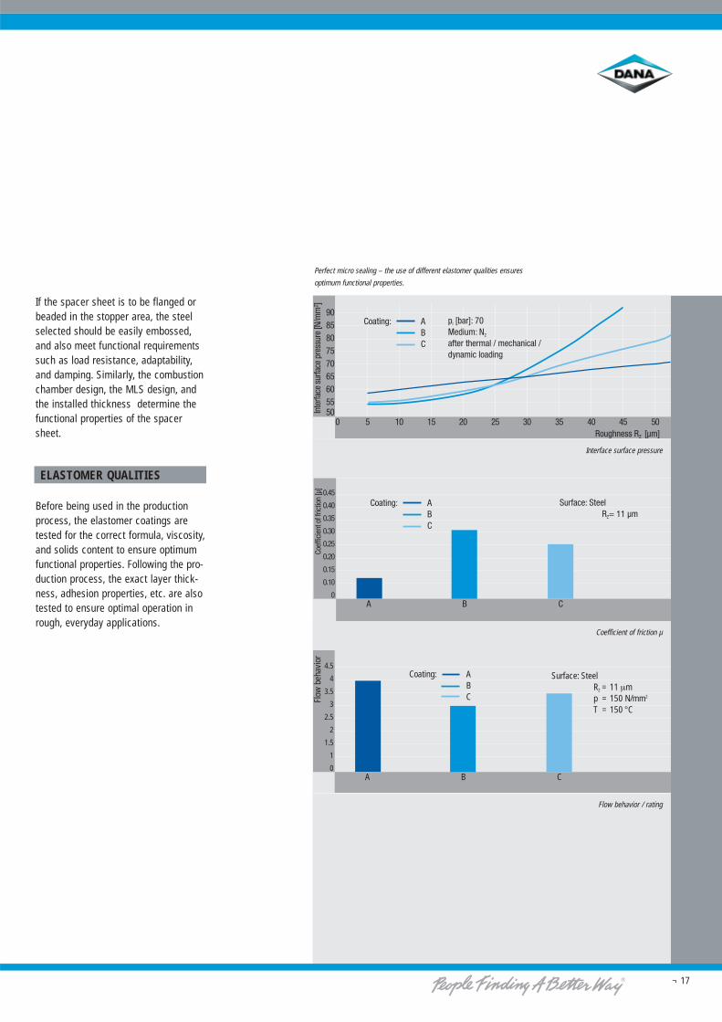
If the spacer sheet is to be flanged orbeaded in the stopper area, the steelselected should be easily embossed,and also meet functional requirementssuch as load resistance, adaptability,and damping. Similarly, the combustionchamber design, the MLS design, andthe installed thickness determine thefunctional properties of the spacersheet.
ELASTOMER QUALITIES
Before being used in the productionprocess, the elastomer coatings aretested for the correct formula, viscosity,and solids content to ensure optimumfunctional properties. Following the pro-duction process, the exact layer thick-ness, adhesion properties, etc. are alsotested to ensure optimal operation inrough, everyday applications.
Interface surface pressure
Coefficient of friction µ
Flow behavior / rating
4.5
4
3.5
3
2.5
2
1.5
1
0A B C
Surface: SteelRZ = 11 μmp = 150 N/mm2
T = 150 °C
Flow
beh
avio
r
ABC
Coating:
Perfect micro sealing – the use of different elastomer qualities ensures
optimum functional properties.
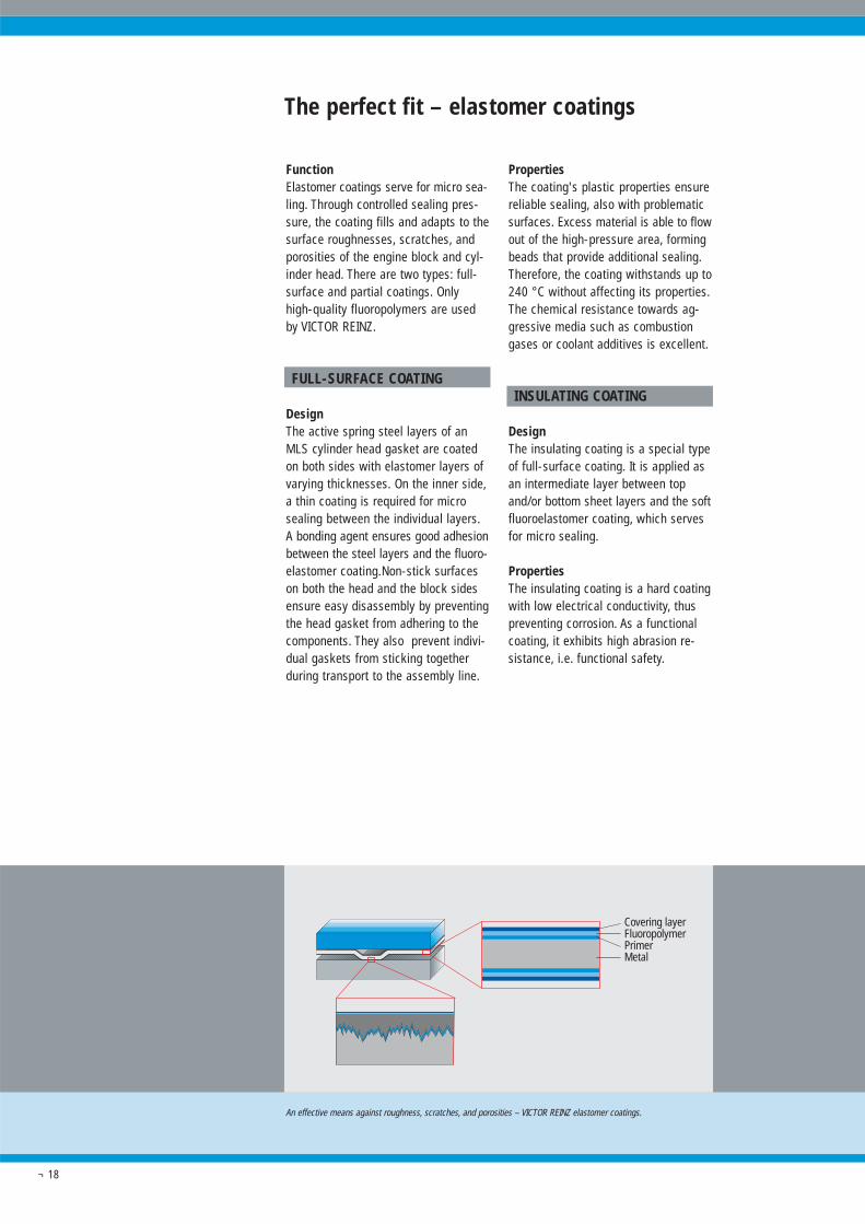
An effective means against roughness, scratches, and porosities – VICTOR REINZ elastomer coatings.
Covering layerFluoropolymerPrimerMetal
¬ 18
FunctionElastomer coatings serve for micro sea-ling. Through controlled sealing pres-sure, the coating fills and adapts to thesurface roughnesses, scratches, andporosities of the engine block and cyl-inder head. There are two types: full-surface and partial coatings. Onlyhigh-quality fluoropolymers are usedby VICTOR REINZ.
FULL-SURFACE COATING
DesignThe active spring steel layers of anMLS cylinder head gasket are coatedon both sides with elastomer layers ofvarying thicknesses. On the inner side,a thin coating is required for microsealing between the individual layers.A bonding agent ensures good adhesionbetween the steel layers and the fluoro-elastomer coating.Non-stick surfaceson both the head and the block sidesensure easy disassembly by preventingthe head gasket from adhering to thecomponents. They also prevent indivi-dual gaskets from sticking togetherduring transport to the assembly line.
The perfect fit – elastomer coatings
PropertiesThe coating's plastic properties ensurereliable sealing, also with problematicsurfaces. Excess material is able to flowout of the high-pressure area, formingbeads that provide additional sealing.Therefore, the coating withstands up to240 °C without affecting its properties.The chemical resistance towards ag-gressive media such as combustiongases or coolant additives is excellent.
INSULATING COATING
DesignThe insulating coating is a special typeof full-surface coating. It is applied asan intermediate layer between topand/or bottom sheet layers and the softfluoroelastomer coating, which servesfor micro sealing.
PropertiesThe insulating coating is a hard coatingwith low electrical conductivity, thuspreventing corrosion. As a functionalcoating, it exhibits high abrasion re-sistance, i.e. functional safety.
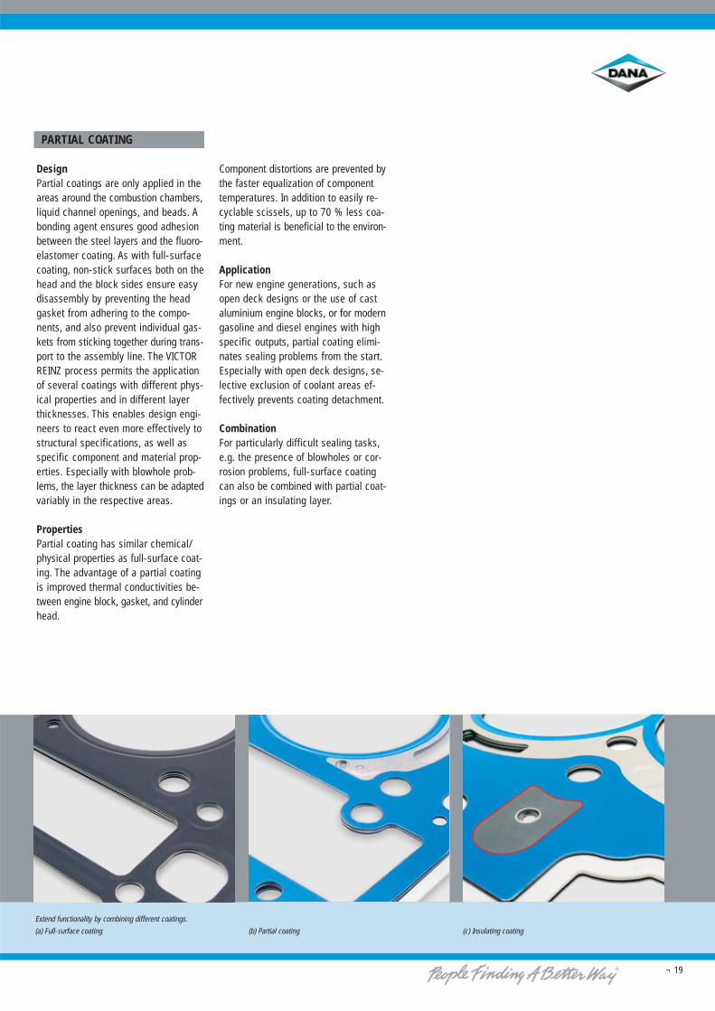
Extend functionality by combining different coatings.
(a) Full-surface coating (b) Partial coating (c) Insulating coating
¬ 19
PARTIAL COATING
DesignPartial coatings are only applied in theareas around the combustion chambers,liquid channel openings, and beads. Abonding agent ensures good adhesionbetween the steel layers and the fluoro-elastomer coating. As with full-surfacecoating, non-stick surfaces both on thehead and the block sides ensure easydisassembly by preventing the headgasket from adhering to the compo-nents, and also prevent individual gas-kets from sticking together during trans-port to the assembly line. The VICTORREINZ process permits the applicationof several coatings with different phys-ical properties and in different layerthicknesses. This enables design engi-neers to react even more effectively tostructural specifications, as well asspecific component and material prop-erties. Especially with blowhole prob-lems, the layer thickness can be adaptedvariably in the respective areas.
PropertiesPartial coating has similar chemical/physical properties as full-surface coat-ing. The advantage of a partial coatingis improved thermal conductivities be-tween engine block, gasket, and cylinderhead.
Component distortions are prevented bythe faster equalization of componenttemperatures. In addition to easily re-cyclable scissels, up to 70 % less coa-ting material is beneficial to the environ-ment.
ApplicationFor new engine generations, such asopen deck designs or the use of castaluminium engine blocks, or for moderngasoline and diesel engines with highspecific outputs, partial coating elimi-nates sealing problems from the start.Especially with open deck designs, se-lective exclusion of coolant areas ef-fectively prevents coating detachment.
CombinationFor particularly difficult sealing tasks,e.g. the presence of blowholes or cor-rosion problems, full-surface coatingcan also be combined with partial coat-ings or an insulating layer.
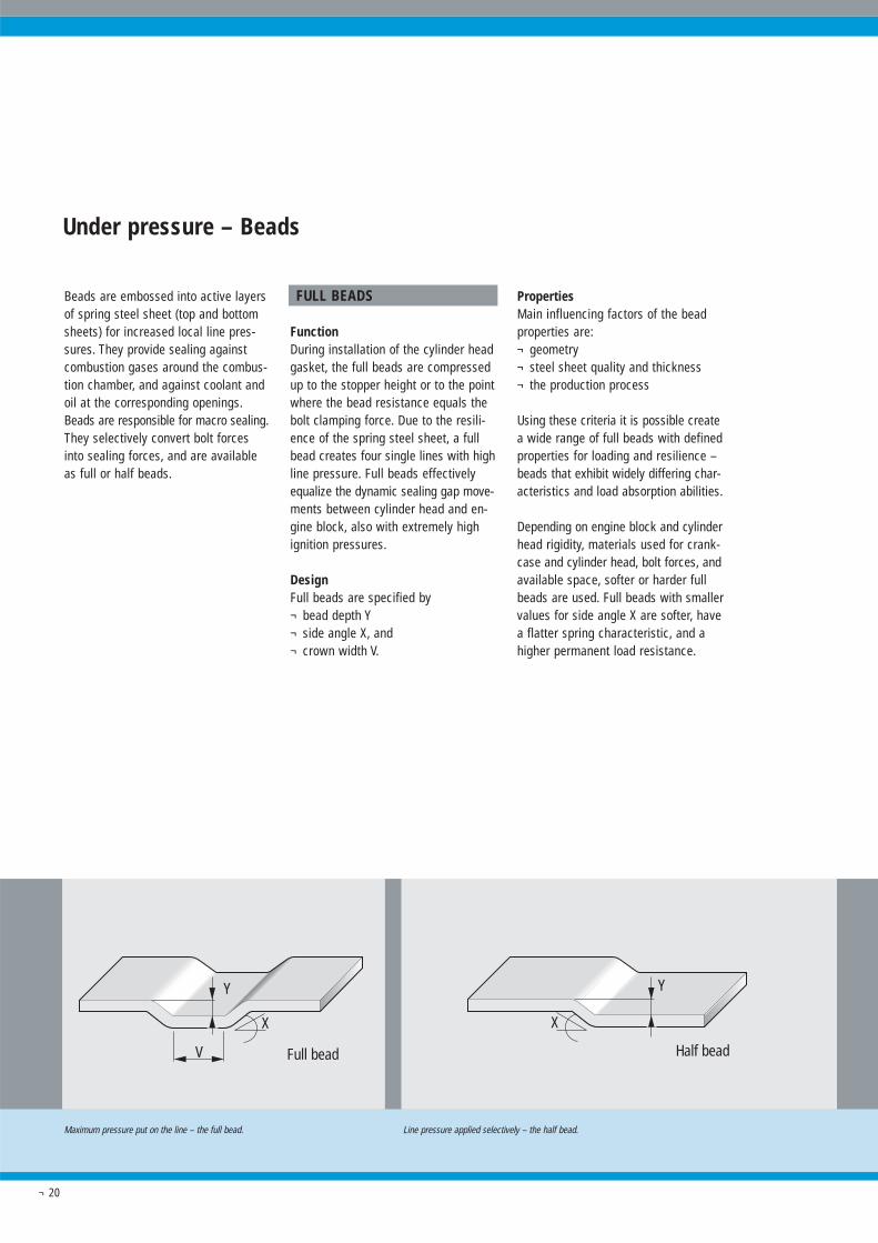
Maximum pressure put on the line – the full bead. Line pressure applied selectively – the half bead.
V
Y
Full bead
X
Half bead
Y
X
¬ 20
Beads are embossed into active layersof spring steel sheet (top and bottomsheets) for increased local line pres-sures. They provide sealing againstcombustion gases around the combus-tion chamber, and against coolant andoil at the corresponding openings.Beads are responsible for macro sealing.They selectively convert bolt forcesinto sealing forces, and are availableas full or half beads.
FULL BEADS
FunctionDuring installation of the cylinder headgasket, the full beads are compressedup to the stopper height or to the pointwhere the bead resistance equals thebolt clamping force. Due to the resili-ence of the spring steel sheet, a fullbead creates four single lines with highline pressure. Full beads effectivelyequalize the dynamic sealing gap move-ments between cylinder head and en-gine block, also with extremely highignition pressures.
DesignFull beads are specified by¬ bead depth Y¬ side angle X, and¬ crown width V.
PropertiesMain influencing factors of the beadproperties are:¬ geometry¬ steel sheet quality and thickness¬ the production process
Using these criteria it is possible createa wide range of full beads with definedproperties for loading and resilience –beads that exhibit widely differing char-acteristics and load absorption abilities.
Depending on engine block and cylinderhead rigidity, materials used for crank-case and cylinder head, bolt forces, andavailable space, softer or harder fullbeads are used. Full beads with smallervalues for side angle X are softer, havea flatter spring characteristic, and ahigher permanent load resistance.
Under pressure – Beads
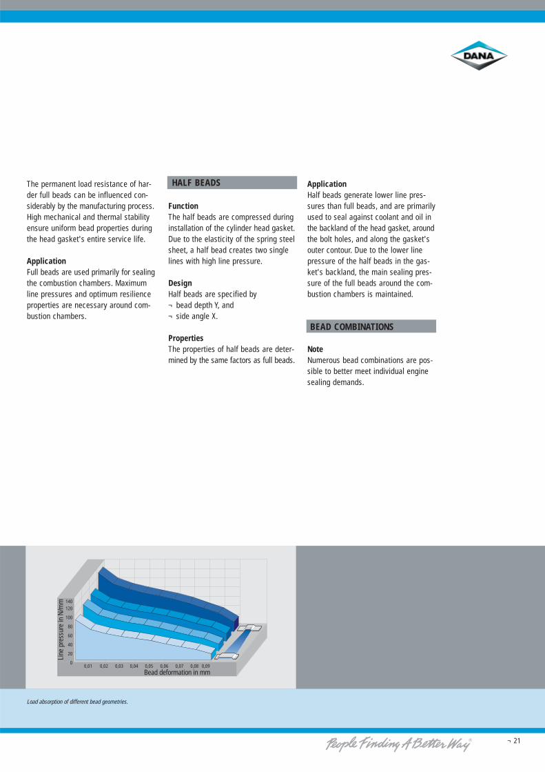
Load absorption of different bead geometries.
0,01 0,02 0,03 0,04 0,05 0,06 0,07 0,08 0,09
120
100
80
60
40
20
0
140
Bead deformation in mm
Line
pre
ssur
e in
N/m
m
¬ 21
HALF BEADS
FunctionThe half beads are compressed duringinstallation of the cylinder head gasket.Due to the elasticity of the spring steelsheet, a half bead creates two singlelines with high line pressure.
DesignHalf beads are specified by¬ bead depth Y, and¬ side angle X.
PropertiesThe properties of half beads are deter-mined by the same factors as full beads.
ApplicationHalf beads generate lower line pres-sures than full beads, and are primarilyused to seal against coolant and oil inthe backland of the head gasket, aroundthe bolt holes, and along the gasket'souter contour. Due to the lower linepressure of the half beads in the gas-ket's backland, the main sealing pres-sure of the full beads around the com-bustion chambers is maintained.
BEAD COMBINATIONS
NoteNumerous bead combinations are pos-sible to better meet individual enginesealing demands.
The permanent load resistance of har-der full beads can be influenced con-siderably by the manufacturing process.High mechanical and thermal stabilityensure uniform bead properties duringthe head gasket's entire service life.
ApplicationFull beads are used primarily for sealingthe combustion chambers. Maximumline pressures and optimum resilienceproperties are necessary around com-bustion chambers.
¬ 22
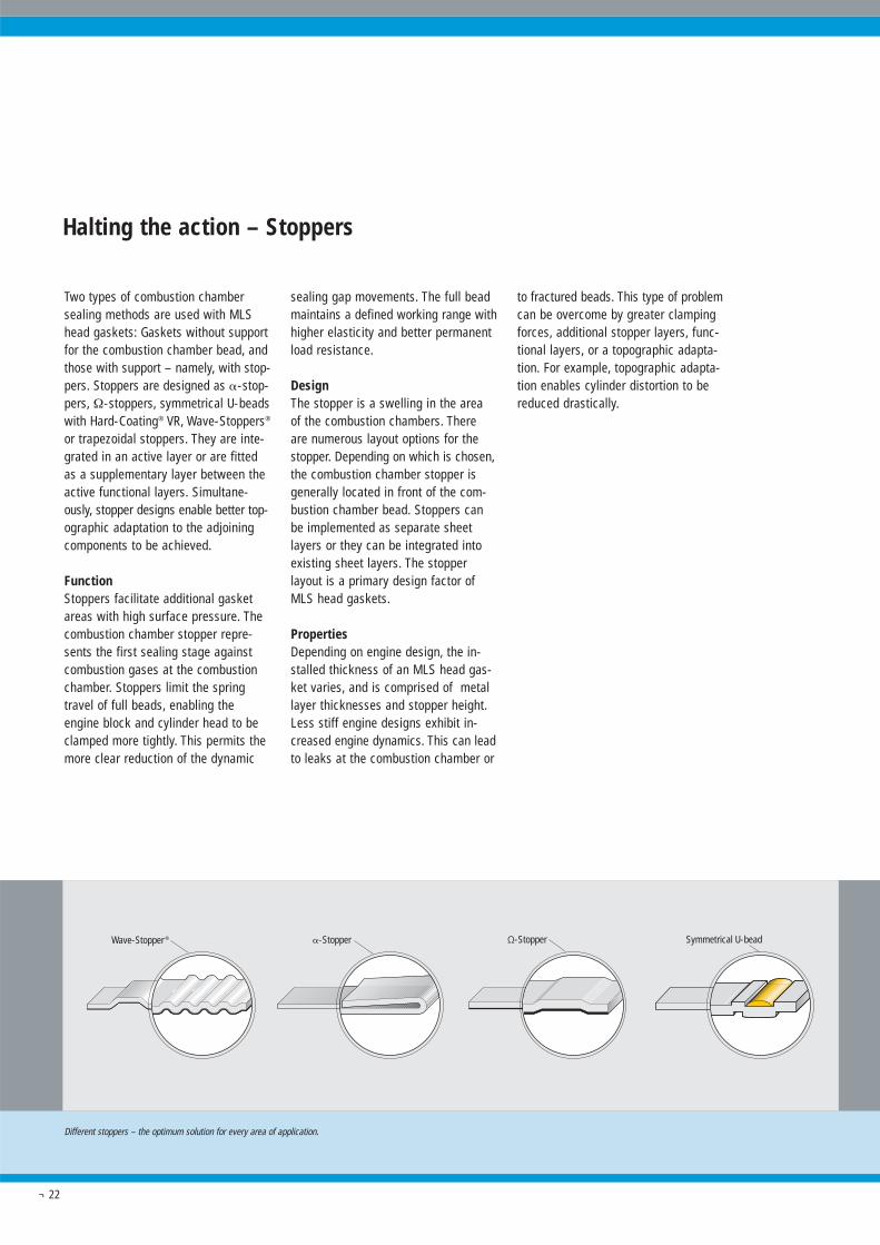
Two types of combustion chambersealing methods are used with MLShead gaskets: Gaskets without supportfor the combustion chamber bead, andthose with support – namely, with stop-pers. Stoppers are designed as �-stop-pers, Ω-stoppers, symmetrical U-beadswith Hard-Coating® VR, Wave-Stoppers®
or trapezoidal stoppers. They are inte-grated in an active layer or are fittedas a supplementary layer between theactive functional layers. Simultane-ously, stopper designs enable better top-ographic adaptation to the adjoiningcomponents to be achieved.
FunctionStoppers facilitate additional gasketareas with high surface pressure. Thecombustion chamber stopper repre-sents the first sealing stage againstcombustion gases at the combustionchamber. Stoppers limit the springtravel of full beads, enabling theengine block and cylinder head to beclamped more tightly. This permits themore clear reduction of the dynamic
sealing gap movements. The full beadmaintains a defined working range withhigher elasticity and better permanentload resistance.
DesignThe stopper is a swelling in the area of the combustion chambers. Thereare numerous layout options for thestopper. Depending on which is chosen,the combustion chamber stopper isgenerally located in front of the com-bustion chamber bead. Stoppers canbe implemented as separate sheetlayers or they can be integrated intoexisting sheet layers. The stopperlayout is a primary design factor ofMLS head gaskets.
PropertiesDepending on engine design, the in-stalled thickness of an MLS head gas-ket varies, and is comprised of metallayer thicknesses and stopper height.Less stiff engine designs exhibit in-creased engine dynamics. This can leadto leaks at the combustion chamber or
to fractured beads. This type of problemcan be overcome by greater clampingforces, additional stopper layers, func-tional layers, or a topographic adapta-tion. For example, topographic adapta-tion enables cylinder distortion to bereduced drastically.
Halting the action – Stoppers
Ω-Stopper�-StopperWave-Stopper ® Symmetrical U-bead
Different stoppers – the optimum solution for every area of application.
¬ 23
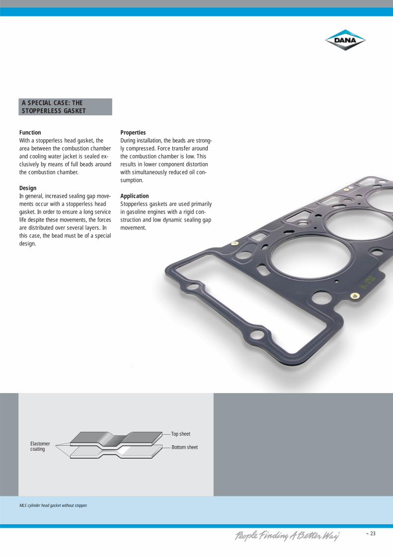
A SPECIAL CASE: THESTOPPERLESS GASKET
FunctionWith a stopperless head gasket, thearea between the combustion chamberand cooling water jacket is sealed ex-clusively by means of full beads aroundthe combustion chamber.
DesignIn general, increased sealing gap move-ments occur with a stopperless headgasket. In order to ensure a long servicelife despite these movements, the forcesare distributed over several layers. Inthis case, the bead must be of a specialdesign.
PropertiesDuring installation, the beads are strong-ly compressed. Force transfer aroundthe combustion chamber is low. Thisresults in lower component distortionwith simultaneously reduced oil con-sumption.
ApplicationStopperless gaskets are used primarilyin gasoline engines with a rigid con-struction and low dynamic sealing gapmovement.
Elastomercoating
Top sheet
Bottom sheet
MLS cylinder head gasket without stopper.
¬ 24
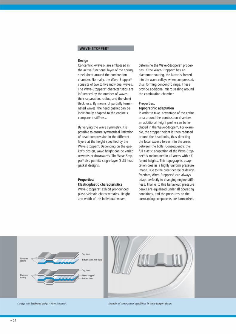
WAVE-STOPPER®
DesignConcentric »waves« are embossed inthe active functional layer of the springsteel sheet around the combustionchamber. Normally, the Wave-Stopper®
consists of two to five individual waves.The Wave-Stoppers® characteristics areinfluenced by the number of waves,their separation, radius, and the sheetthickness. By means of partially termi-nated waves, the head gasket can beindividually adapted to the engine'scomponent stiffness.
By varying the wave symmetry, it ispossible to ensure symmetrical limitationof bead compression in the differentlayers at the height specified by theWave-Stopper®. Depending on the gas-ket's design, wave height can be variedupwards or downwards. The Wave-Stop-per® also permits single-layer (SLS) headgasket designs.
Properties:Elastic/plastic characteristicsWave-Stoppers® exhibit pronouncedplastic/elastic characteristics. Heightand width of the individual waves
determine the Wave-Stoppers® proper-ties. If the Wave-Stopper® has anelastomer coating, the latter is forcedinto the wave valleys when compressed,thus forming concentric rings. Theseprovide additional micro sealing aroundthe combustion chamber.
Properties:Topographic adaptationIn order to take advantage of the entirearea around the combustion chamber,an additional height profile can be in-cluded in the Wave-Stopper®. For exam-ple, the stopper height is then reducedaround the head bolts, thus directingthe local excess forces into the areasbetween the bolts. Consequently, thefull elastic adaptation of the Wave-Stop-per® is maintained in all areas with dif-ferent heights. This topographic adap-tation creates a highly uniform pressureimage. Due to the great degree of designfreedom, Wave-Stoppers® can alwaysadapt perfectly to changing engine stiff-ness. Thanks to this behaviour, pressurepeaks are equalized under all operatingconditions, and the pressures on thesurrounding components are harmonized.
Elastomercoating
Top sheet
Bottom sheet with wave
Top sheet
Wave-Stopper ®
Bottom sheet
Elastomercoating
Concept with freedom of design – Wave-Stoppers®. Examples of constructional possibilities for Wave-Stopper® design.
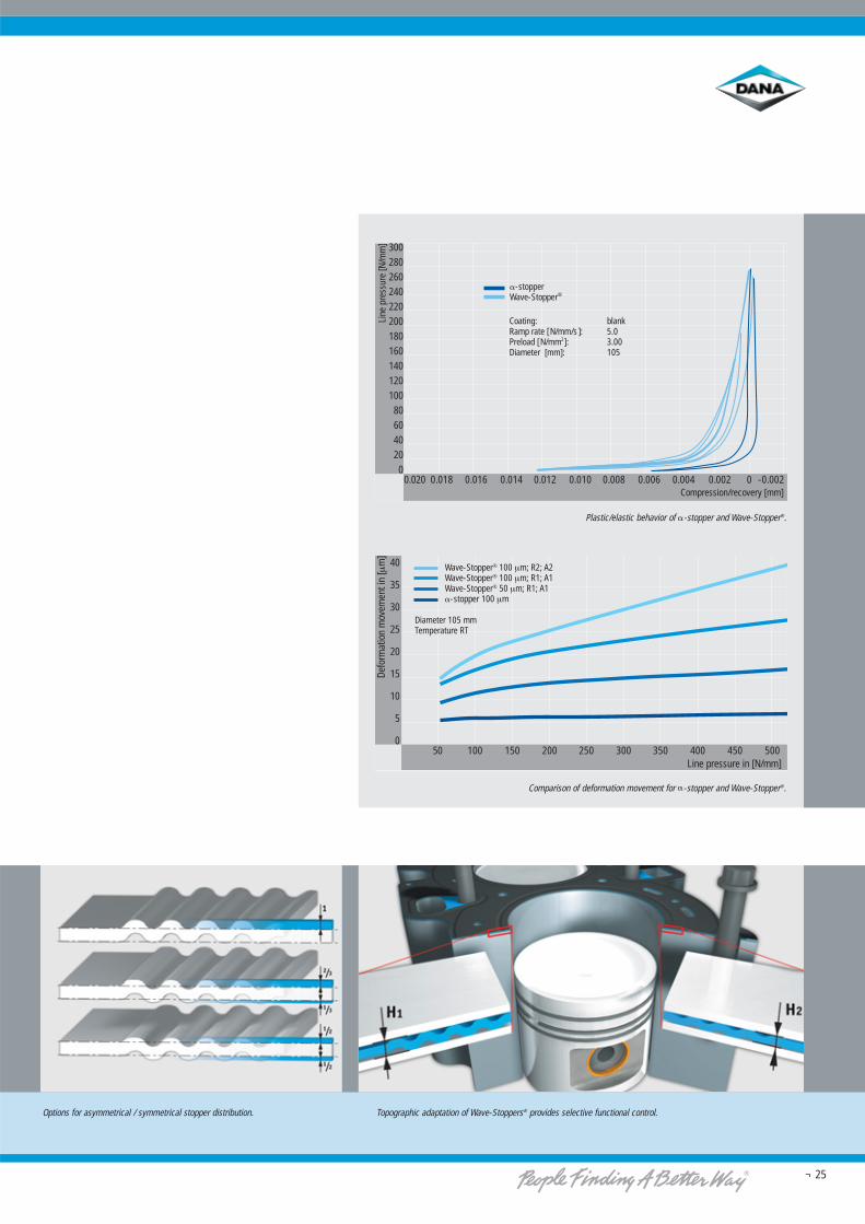
Line
pre
ssur
e [N
/mm
] 300280260240220200180160140120100806040200
0.020 0.018 0.016 0.014 0.012 0.010 0.008 0.006 0.004 0.002 0 -0.002Compression/recovery [mm]
�-stopperWave-Stopper®
Coating: blankRamp rate [N/mm/s]: 5.0Preload [N/mm2]: 3.00Diameter [mm]: 105
40
35
30
25
20
15
10
5
0
Line pressure in [N/mm]50 100 150 200 250 300 350 400 450 500
Defo
rmat
ion
mov
emen
t in
[μm
]
Wave-Stopper® 100 μm; R2; A2Wave-Stopper® 100 μm; R1; A1Wave-Stopper® 50 μm; R1; A1�-stopper 100 μm
Diameter 105 mmTemperature RT
¬ 25
Options for asymmetrical / symmetrical stopper distribution. Topographic adaptation of Wave-Stoppers® provides selective functional control.
Plastic/elastic behavior of �-stopper and Wave-Stopper®.
Comparison of deformation movement for �-stopper and Wave-Stopper®.
¬ 26
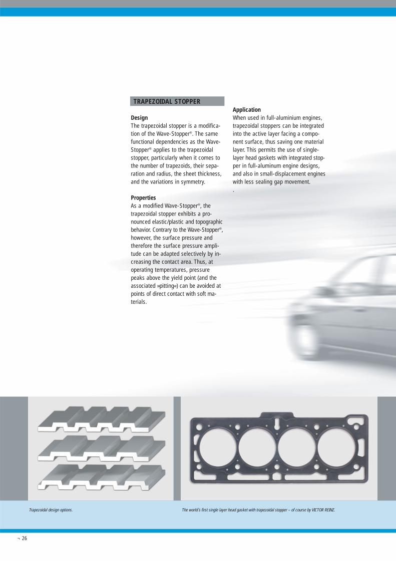
TRAPEZOIDAL STOPPER
DesignThe trapezoidal stopper is a modifica-tion of the Wave-Stopper®. The samefunctional dependencies as the Wave-Stopper® applies to the trapezoidalstopper, particularly when it comes tothe number of trapezoids, their sepa-ration and radius, the sheet thickness,and the variations in symmetry.
PropertiesAs a modified Wave-Stopper®, thetrapezoidal stopper exhibits a pro-nounced elastic/plastic and topographicbehavior. Contrary to the Wave-Stopper®,however, the surface pressure andtherefore the surface pressure ampli-tude can be adapted selectively by in-creasing the contact area. Thus, atoperating temperatures, pressurepeaks above the yield point (and theassociated »pitting«) can be avoided atpoints of direct contact with soft ma-terials.
ApplicationWhen used in full-aluminium engines,trapezoidal stoppers can be integratedinto the active layer facing a compo-nent surface, thus saving one materiallayer. This permits the use of single-layer head gaskets with integrated stop-per in full-aluminum engine designs,and also in small-displacement engineswith less sealing gap movement..
Trapezoidal design options. The world`s first single layer head gasket with trapezoidal stopper – of course by VICTOR REINZ.
¬ 27
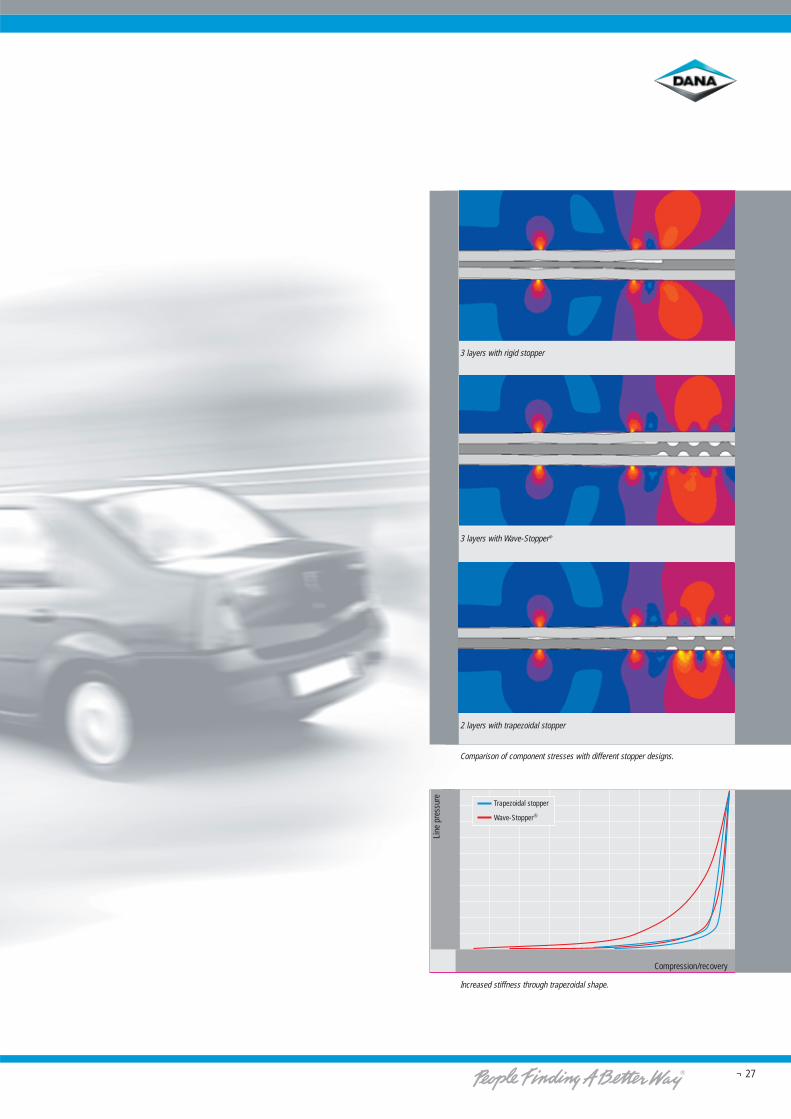
3 layers with Wave-Stopper®
2 layers with trapezoidal stopper
Comparison of component stresses with different stopper designs.
3 layers with rigid stopper
Increased stiffness through trapezoidal shape.
400
350
300
250
200
150
100
50
0
Line
pre
ssur
e
Trapezoidal stopper
Wave-Stopper®
Compression/recovery
Top sheet�-stopper
Bottom sheet
Elastomercoating
Top sheet�-stopper
Bottom sheet
Elastomercoating
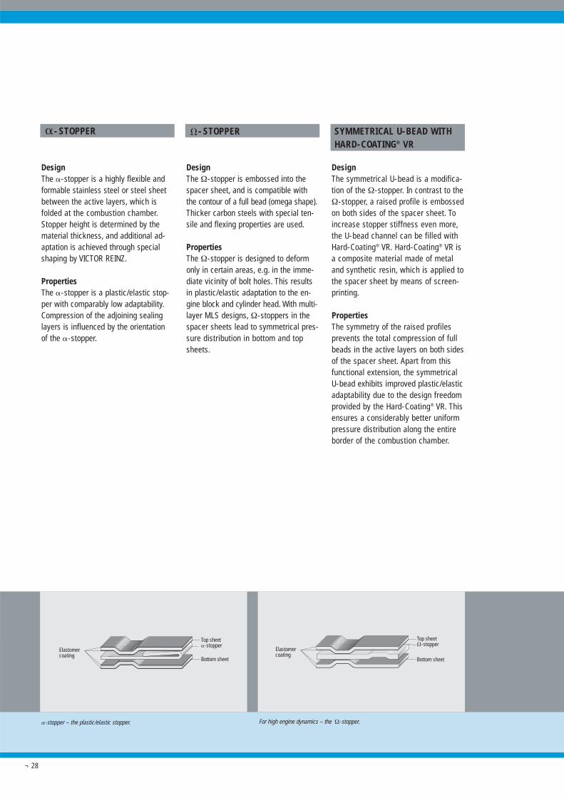
�-stopper – the plastic/elastic stopper. For high engine dynamics – the Ω-stopper.
¬ 28
�- STOPPER
DesignThe �-stopper is a highly flexible andformable stainless steel or steel sheetbetween the active layers, which isfolded at the combustion chamber.Stopper height is determined by thematerial thickness, and additional ad-aptation is achieved through specialshaping by VICTOR REINZ.
PropertiesThe �-stopper is a plastic/elastic stop-per with comparably low adaptability.Compression of the adjoining sealinglayers is influenced by the orientation of the �-stopper.
�- STOPPER
DesignThe Ω-stopper is embossed into thespacer sheet, and is compatible withthe contour of a full bead (omega shape).Thicker carbon steels with special ten-sile and flexing properties are used.
PropertiesThe Ω-stopper is designed to deformonly in certain areas, e.g. in the imme-diate vicinity of bolt holes. This resultsin plastic/elastic adaptation to the en-gine block and cylinder head. With multi-layer MLS designs, Ω-stoppers in thespacer sheets lead to symmetrical pres-sure distribution in bottom and topsheets.
SYMMETRICAL U-BEAD WITHHARD-COATING® VR
DesignThe symmetrical U-bead is a modifica-tion of the Ω-stopper. In contrast to theΩ-stopper, a raised profile is embossedon both sides of the spacer sheet. Toincrease stopper stiffness even more,the U-bead channel can be filled withHard-Coating® VR. Hard-Coating® VR isa composite material made of metaland synthetic resin, which is applied tothe spacer sheet by means of screen-printing.
PropertiesThe symmetry of the raised profilesprevents the total compression of fullbeads in the active layers on both sidesof the spacer sheet. Apart from thisfunctional extension, the symmetricalU-bead exhibits improved plastic/elasticadaptability due to the design freedomprovided by the Hard-Coating® VR. Thisensures a considerably better uniformpressure distribution along the entireborder of the combustion chamber.
Elastomercoating
Top sheet
Symmetrical U-bead(spacer sheet withHard-Coating® VR)Bottom sheet
Even more adaptable – symmetrical U-bead with Hard-Coating ® VR
¬ 29
Hard-Coating® VR is an elastic/plasticstopper. Because of its variable heightand width, it can be adapted optimallyto the stiffness of the surroundingcomponents. The most defining char-acteristic of Hard-Coating® VR lies inits higher non-compressibility underload. Moreover, Hard-Coating® VR hasvery good media resistance, and with-stands temperature up to 240 °C.
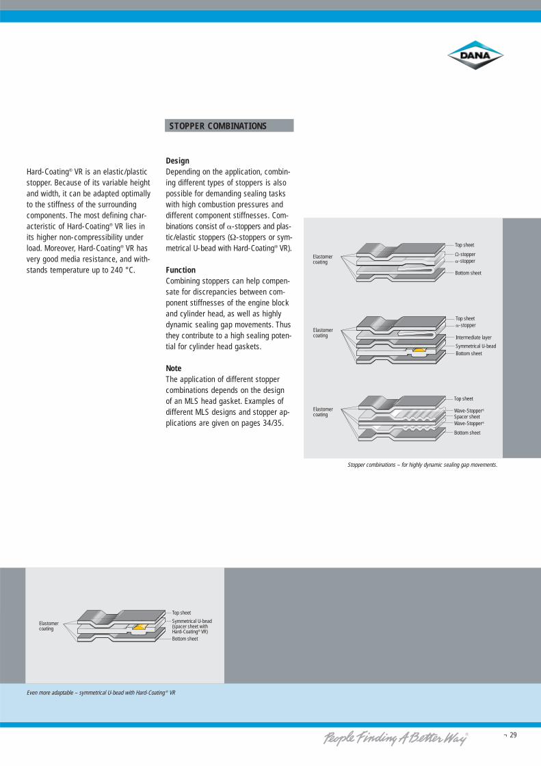
STOPPER COMBINATIONS
DesignDepending on the application, combin-ing different types of stoppers is alsopossible for demanding sealing taskswith high combustion pressures anddifferent component stiffnesses. Com-binations consist of �-stoppers and plas-tic/elastic stoppers (Ω-stoppers or sym-metrical U-bead with Hard-Coating® VR).
FunctionCombining stoppers can help compen-sate for discrepancies between com-ponent stiffnesses of the engine blockand cylinder head, as well as highlydynamic sealing gap movements. Thusthey contribute to a high sealing poten-tial for cylinder head gaskets.
NoteThe application of different stoppercombinations depends on the design of an MLS head gasket. Examples ofdifferent MLS designs and stopper ap-plications are given on pages 34/35.
Elastomercoating
Top sheet
Wave-Stopper®
Spacer sheetWave-Stopper®
Bottom sheet
Elastomercoating
Top sheet
Ω-stopper�-stopper
Bottom sheet
Top sheet�-stopper
Intermediate layer
Symmetrical U-beadBottom sheet
Elastomercoating
Stopper combinations – for highly dynamic sealing gap movements.
¬ 30
Comparison of cylinder shape without additional measures, and with integrated backland stopper.
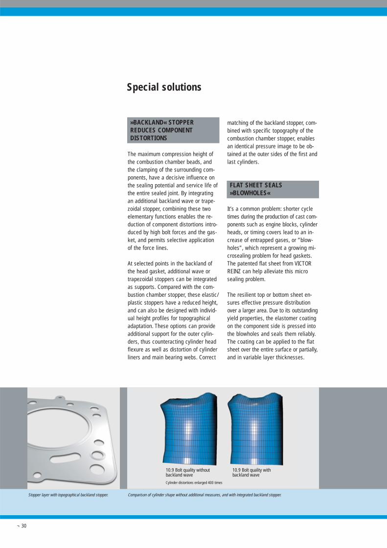
»BACKLAND« STOPPERREDUCES COMPONENTDISTORTIONS
The maximum compression height ofthe combustion chamber beads, andthe clamping of the surrounding com-ponents, have a decisive influence onthe sealing potential and service life ofthe entire sealed joint. By integratingan additional backland wave or trape-zoidal stopper, combining these twoelementary functions enables the re-duction of component distortions intro-duced by high bolt forces and the gas-ket, and permits selective applicationof the force lines.
At selected points in the backland ofthe head gasket, additional wave ortrapezoidal stoppers can be integratedas supports. Compared with the com-bustion chamber stopper, these elastic/plastic stoppers have a reduced height,and can also be designed with individ-ual height profiles for topographicaladaptation. These options can provideadditional support for the outer cylin-ders, thus counteracting cylinder headflexure as well as distortion of cylinderliners and main bearing webs. Correct
matching of the backland stopper, com-bined with specific topography of thecombustion chamber stopper, enablesan identical pressure image to be ob-tained at the outer sides of the first andlast cylinders.
FLAT SHEET SEALS»BLOWHOLES«
It’s a common problem: shorter cycletimes during the production of cast com-ponents such as engine blocks, cylinderheads, or timing covers lead to an in-crease of entrapped gases, or ”blow-holes”, which represent a growing mi-crosealing problem for head gaskets.The patented flat sheet from VICTORREINZ can help alleviate this microsealing problem.
The resilient top or bottom sheet en-sures effective pressure distributionover a larger area. Due to its outstandingyield properties, the elastomer coatingon the component side is pressed intothe blowholes and seals them reliably.The coating can be applied to the flatsheet over the entire surface or partially,and in variable layer thicknesses.
Special solutions
Stopper layer with topographical backland stopper.
10.9 Bolt quality withoutbackland wave
10.9 Bolt quality withbackland wave
Cylinder distortions enlarged 400 times
¬ 31
Secure sealing of blowholes – with the patented flat sheet solution from VICTOR REINZ.
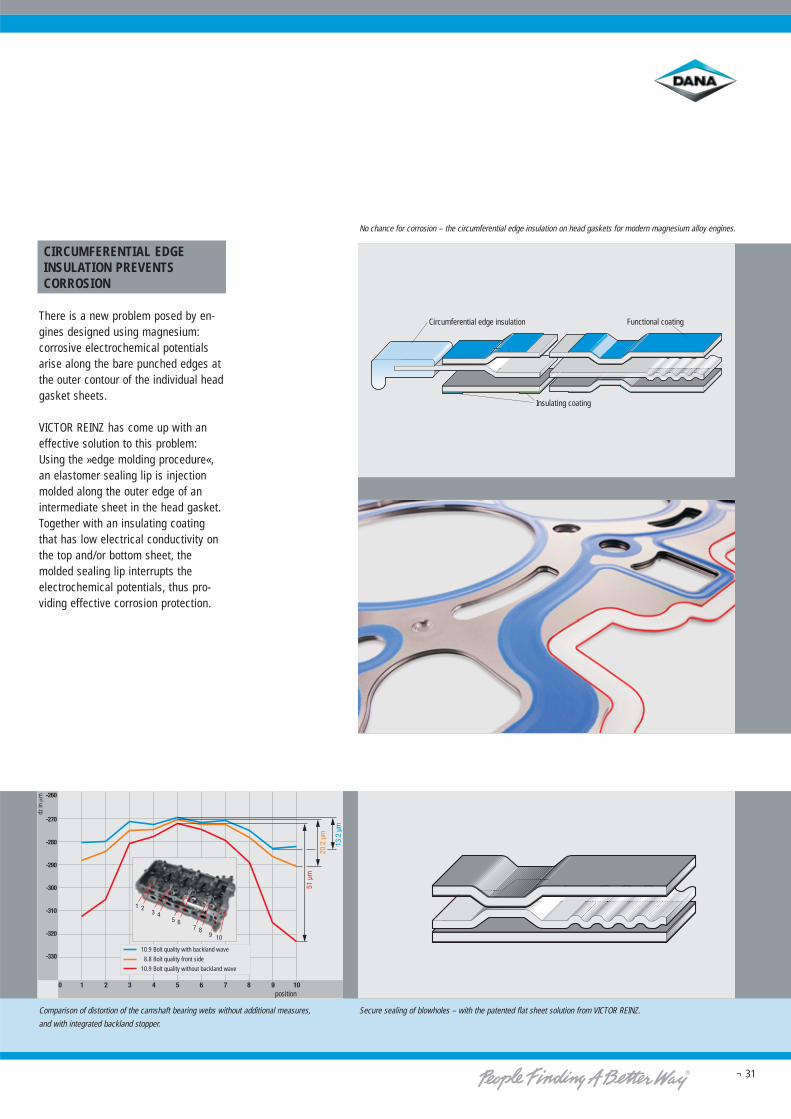
No chance for corrosion – the circumferential edge insulation on head gaskets for modern magnesium alloy engines.
CIRCUMFERENTIAL EDGEINSULATION PREVENTSCORROSION
There is a new problem posed by en-gines designed using magnesium:corrosive electrochemical potentialsarise along the bare punched edges atthe outer contour of the individual headgasket sheets.
VICTOR REINZ has come up with aneffective solution to this problem:Using the »edge molding procedure«,an elastomer sealing lip is injectionmolded along the outer edge of anintermediate sheet in the head gasket.Together with an insulating coatingthat has low electrical conductivity onthe top and/or bottom sheet, themolded sealing lip interrupts theelectrochemical potentials, thus pro-viding effective corrosion protection.
Functional coatingCircumferential edge insulation
Insulating coating
dz in
μm
position
10.9 Bolt quality with backland wave
8.8 Bolt quality front side
10.9 Bolt quality without backland wave
Comparison of distortion of the camshaft bearing webs without additional measures,
and with integrated backland stopper.
¬ 32
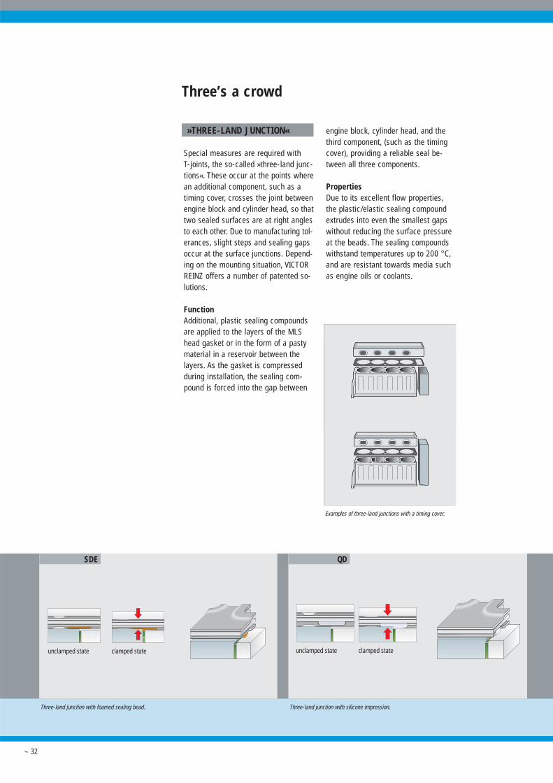
»THREE-LAND JUNCTION«
Special measures are required with T-joints, the so-called »three-land junc-tions«. These occur at the points wherean additional component, such as atiming cover, crosses the joint betweenengine block and cylinder head, so thattwo sealed surfaces are at right anglesto each other. Due to manufacturing tol-erances, slight steps and sealing gapsoccur at the surface junctions. Depend-ing on the mounting situation, VICTORREINZ offers a number of patented so-lutions.
FunctionAdditional, plastic sealing compoundsare applied to the layers of the MLShead gasket or in the form of a pastymaterial in a reservoir between thelayers. As the gasket is compressedduring installation, the sealing com-pound is forced into the gap between
engine block, cylinder head, and thethird component, (such as the timingcover), providing a reliable seal be-tween all three components.
PropertiesDue to its excellent flow properties,the plastic/elastic sealing compoundextrudes into even the smallest gapswithout reducing the surface pressureat the beads. The sealing compoundswithstand temperatures up to 200 °C,and are resistant towards media suchas engine oils or coolants.
Three’s a crowd
Three-land junction with foamed sealing bead. Three-land junction with silicone impression.
unclamped state clamped state unclamped state clamped state
Examples of three-land junctions with a timing cover.
QDSDE
¬ 33
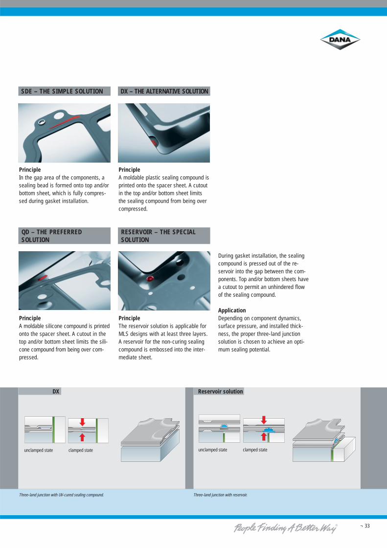
SDE – THE SIMPLE SOLUTION
PrincipleIn the gap area of the components, asealing bead is formed onto top and/orbottom sheet, which is fully compres-sed during gasket installation.
QD – THE PREFERREDSOLUTION
PrincipleA moldable silicone compound is printedonto the spacer sheet. A cutout in thetop and/or bottom sheet limits the sili-cone compound from being over com-pressed.
DX – THE ALTERNATIVE SOLUTION
PrincipleA moldable plastic sealing compound isprinted onto the spacer sheet. A cutoutin the top and/or bottom sheet limitsthe sealing compound from being overcompressed.
RESERVOIR – THE SPECIALSOLUTION
PrincipleThe reservoir solution is applicable forMLS designs with at least three layers.A reservoir for the non-curing sealingcompound is embossed into the inter-mediate sheet.
During gasket installation, the sealingcompound is pressed out of the re-servoir into the gap between the com-ponents. Top and/or bottom sheets havea cutout to permit an unhindered flowof the sealing compound.
ApplicationDepending on component dynamics,surface pressure, and installed thick-ness, the proper three-land junctionsolution is chosen to achieve an opti-mum sealing potential.
Three-land junction with UV-cured sealing compound. Three-land junction with reservoir.
unclamped state clamped state unclamped state clamped state
Reservoir solutionDX
Application examples for MLS designs
Special engines
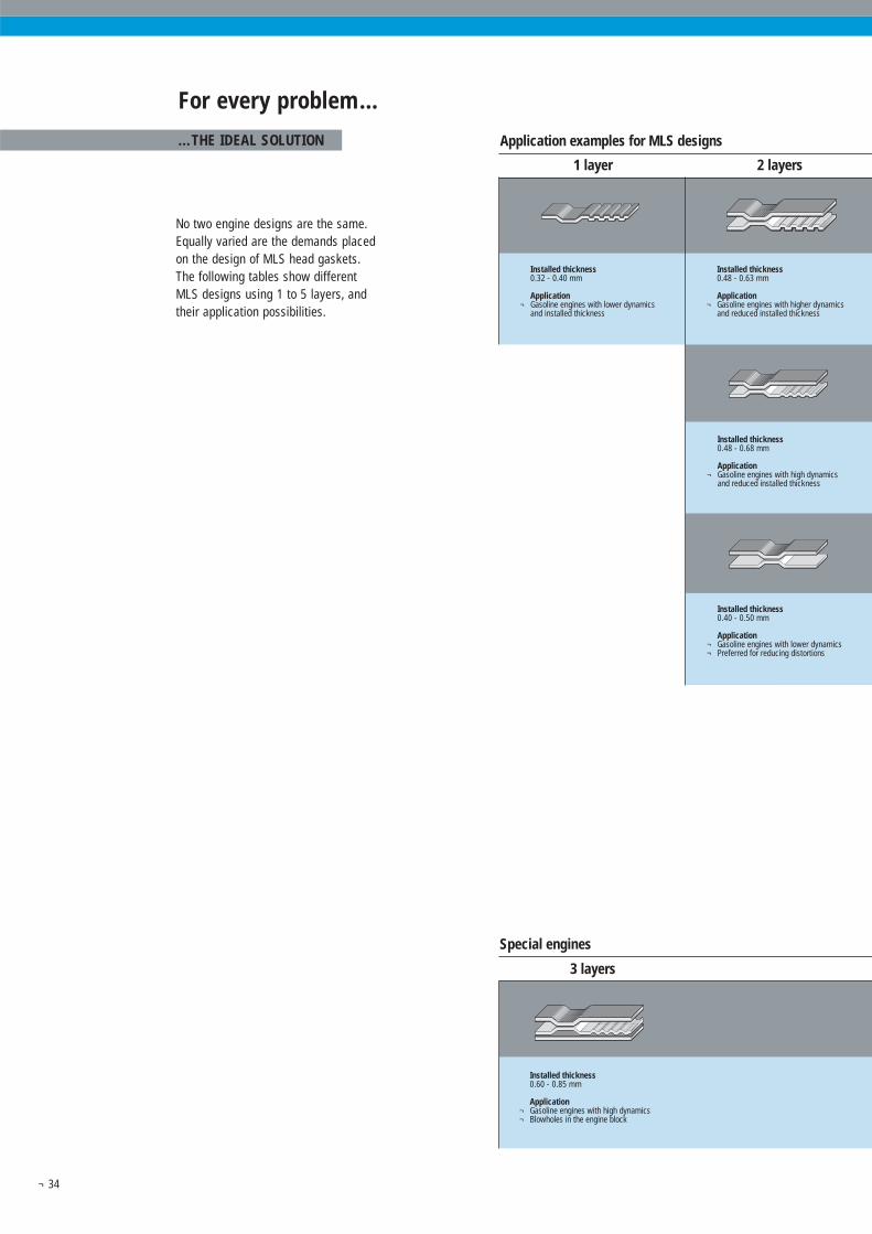
Installed thickness0.32 - 0.40 mm
Application¬ Gasoline engines with lower dynamics
and installed thickness
Installed thickness 0.48 - 0.63 mm
Application¬ Gasoline engines with higher dynamics
and reduced installed thickness
Installed thickness0.48 - 0.68 mm
Application¬ Gasoline engines with high dynamics
and reduced installed thickness
Installed thickness0.40 - 0.50 mm
Application¬ Gasoline engines with lower dynamics¬ Preferred for reducing distortions
1 layer 2 layers
3 layers
Installed thickness0.60 - 0.85 mm
Application¬ Gasoline engines with high dynamics¬ Blowholes in the engine block
¬ 34
For every problem...
...THE IDEAL SOLUTION
No two engine designs are the same.Equally varied are the demands placedon the design of MLS head gaskets.The following tables show differentMLS designs using 1 to 5 layers, andtheir application possibilities.
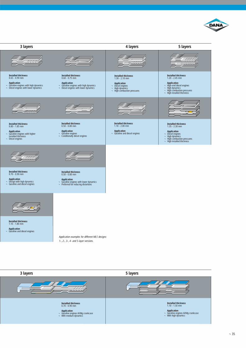
Installed thickness0.65 - 0.90 mm
Application¬ Gasoline engines with high dynamics¬ Diesel engines with lower dynamics
Installed thickness0.60 - 0.75 mm
Application¬ Gasoline engines with high dynamics¬ Diesel engines with lower dynamics
Installed thickness1.30 - 2.10 mm
Application¬ Diesel engines¬ High dynamics¬ High combustion pressures
Installed thickness1.20 - 2.45 mm
Application¬ High-end diesel engines¬ High dynamics¬ High combustion pressures¬ High installed thickness
Installed thickness0.80 - 1.85 mm
Application¬ Gasoline engines with higher
installed thickness¬ Diesel engines
Installed thickness0.50 - 0.80 mm
Application¬ Gasoline engines¬ Conditionally diesel engines
Installed thickness1.10 - 2.00 mm
Application¬ Gasoline and diesel engines
Installed thickness1.35 - 2.30 mm
Application¬ Diesel engines¬ High dynamics¬ High combustion pressures¬ High installed thickness
Installed thickness0.70 - 0.90 mm
Application¬ Design with high dynamics¬ Gasoline and diesel engines
Installed thickness0.50 - 0.80 mm
Application¬ Gasoline engines with lower dynamics¬ Preferred for reducing distortions
Installed thickness1.10 - 1.80 mm
Application¬ Gasoline and diesel engines
3 layers 4 layers 5 layers
3 layers 5 layers
Installed thickness0.70 - 0.90 mm
Application¬ Gasoline engines Al/Mg crankcase¬ With medium dynamics
Installed thickness1.10 - 1.50 mm
Application¬ Gasoline engines Al/Mg crankcase¬ With high dynamics
¬ 35
Application examples for different MLS designs:
1-, 2-, 3-, 4- and 5-layer versions.
60 757065 80
¬ 36
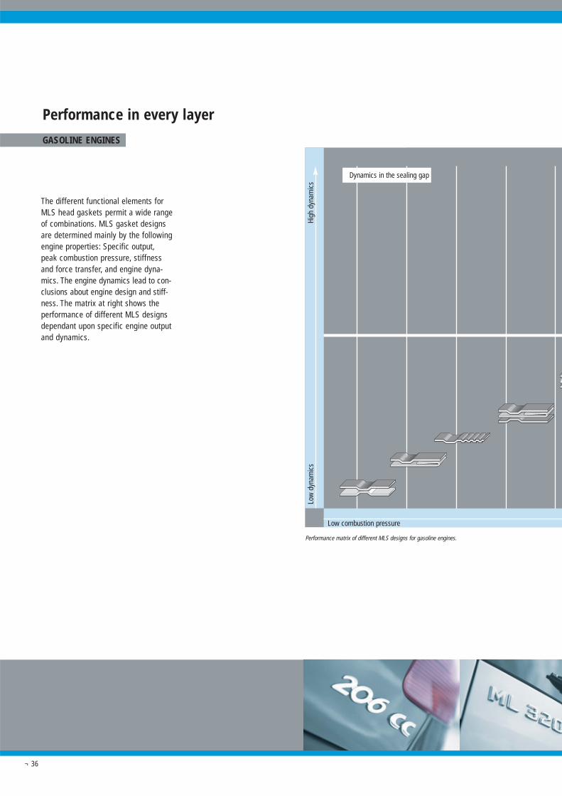
Performance in every layer
GASOLINE ENGINES
High
dyn
amic
sLo
w d
ynam
ics
Low combustion pressure
The different functional elements forMLS head gaskets permit a wide rangeof combinations. MLS gasket designsare determined mainly by the followingengine properties: Specific output,peak combustion pressure, stiffnessand force transfer, and engine dyna-mics. The engine dynamics lead to con-clusions about engine design and stiff-ness. The matrix at right shows theperformance of different MLS designsdependant upon specific engine outputand dynamics.
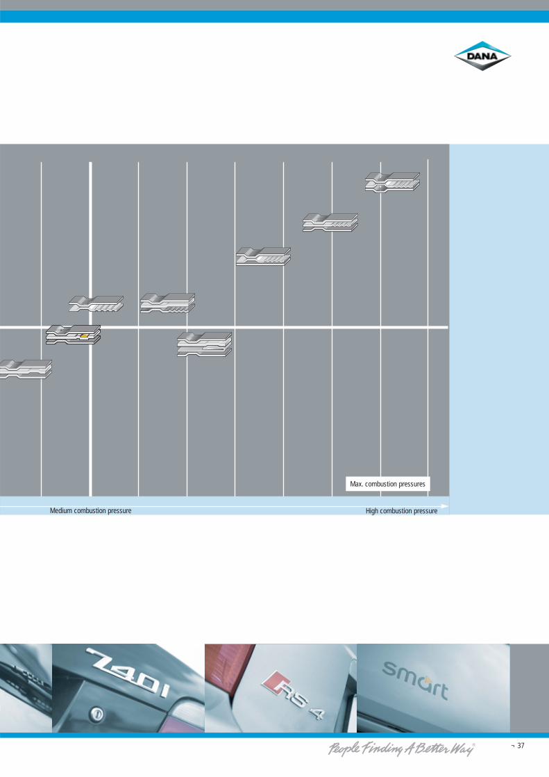
Performance matrix of different MLS designs for gasoline engines.
Dynamics in the sealing gap
9085 95 100 105 110 115 120 [bar]125
¬ 37
High combustion pressureMedium combustion pressure
Max. combustion pressures
100 110 120 130
¬ 38
High
dyn
amic
sLo
w d
ynam
ics
Low combustion pressure
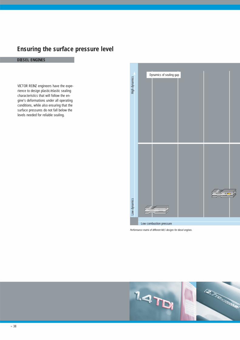
Ensuring the surface pressure level
DIESEL ENGINES
VICTOR REINZ engineers have the expe-rience to design plastic/elastic sealingcharacteristics that will follow the en-gine's deformations under all operatingconditions, while also ensuring that thesurface pressures do not fall below thelevels needed for reliable sealing.
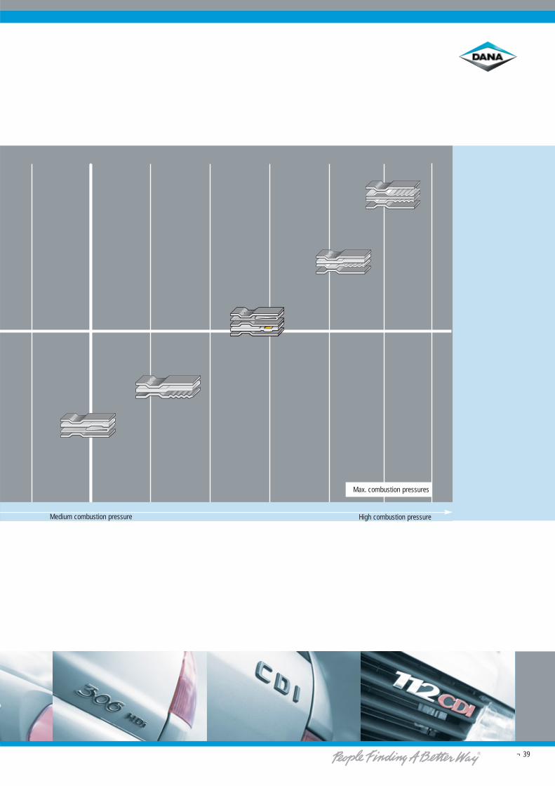
Performance matrix of different MLS designs for diesel engines.
Dynamics of sealing gap
150 160 170 180 190 200140 [bar]210
¬ 39
High combustion pressureMedium combustion pressure
Max. combustion pressures
¬ 40
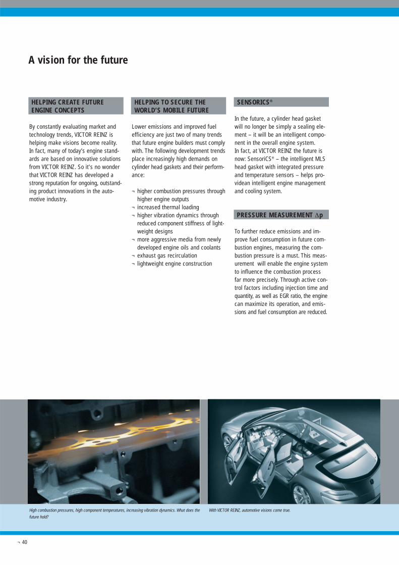
High combustion pressures, high component temperatures, increasing vibration dynamics. What does the
future hold?
With VICTOR REINZ, automotive visions come true.
HELPING CREATE FUTUREENGINE CONCEPTS
By constantly evaluating market andtechnology trends, VICTOR REINZ ishelping make visions become reality.In fact, many of today’s engine stand-ards are based on innovative solutionsfrom VICTOR REINZ. So it's no wonderthat VICTOR REINZ has developed astrong reputation for ongoing, outstand-ing product innovations in the auto-motive industry.
HELPING TO SECURE THEWORLD’S MOBILE FUTURE
Lower emissions and improved fuelefficiency are just two of many trendsthat future engine builders must complywith. The following development trendsplace increasingly high demands oncylinder head gaskets and their perform-ance:
¬ higher combustion pressures throughhigher engine outputs
¬ increased thermal loading¬ higher vibration dynamics through
reduced component stiffness of light-weight designs
¬ more aggressive media from newlydeveloped engine oils and coolants
¬ exhaust gas recirculation¬ lightweight engine construction
SENSORICS®
In the future, a cylinder head gasketwill no longer be simply a sealing ele-ment – it will be an intelligent compo-nent in the overall engine system.In fact, at VICTOR REINZ the future isnow: SensoriCS® – the intelligent MLShead gasket with integrated pressureand temperature sensors – helps pro-videan intelligent engine managementand cooling system.
PRESSURE MEASUREMENT Δp
To further reduce emissions and im-prove fuel consumption in future com-bustion engines, measuring the com-bustion pressure is a must. This meas-urement will enable the engine systemto influence the combustion processfar more precisely. Through active con-trol factors including injection time andquantity, as well as EGR ratio, the enginecan maximize its operation, and emis-sions and fuel consumption are reduced.
A vision for the future
¬ 41
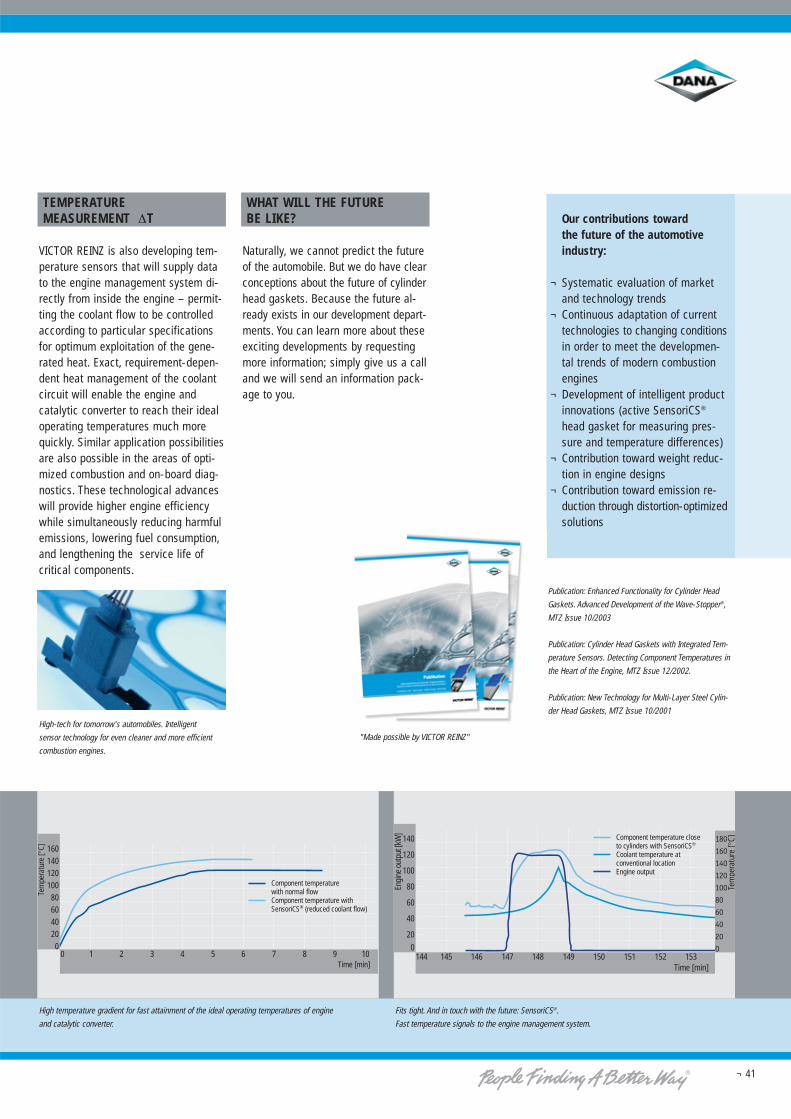
High temperature gradient for fast attainment of the ideal operating temperatures of engine
and catalytic converter.
Fits tight. And in touch with the future: SensoriCS®.
Fast temperature signals to the engine management system.
High-tech for tomorrow's automobiles. Intelligent
sensor technology for even cleaner and more efficient
combustion engines.
Tem
per
atur
[°C]
Zeit [min]
0 1 2 3 4 5 6 7 8 9 10
Component temperaturewith normal flowComponent temperature withSensoriCS® (reduced coolant flow)
160140120100806040200
Time [min]
Tem
pera
ture
[°C]
144 145 146 147 148 149 150 151 152 153
Component temperature closeto cylinders with SensoriCS®
Coolant temperature atconventional locationEngine output
Time [min]
180
160
140
120
100
80
60
40
20
0
Tem
pera
ture
[°C]140
120
100
80
60
40
20
0
Engi
ne o
utpu
t [kW
]
TEMPERATURE MEASUREMENT ΔT
VICTOR REINZ is also developing tem-perature sensors that will supply datato the engine management system di-rectly from inside the engine – permit-ting the coolant flow to be controlledaccording to particular specificationsfor optimum exploitation of the gene-rated heat. Exact, requirement-depen-dent heat management of the coolantcircuit will enable the engine andcatalytic converter to reach their idealoperating temperatures much morequickly. Similar application possibilitiesare also possible in the areas of opti-mized combustion and on-board diag-nostics. These technological advanceswill provide higher engine efficiencywhile simultaneously reducing harmfulemissions, lowering fuel consumption,and lengthening the service life ofcritical components.
WHAT WILL THE FUTURE BE LIKE?
Naturally, we cannot predict the futureof the automobile. But we do have clearconceptions about the future of cylinderhead gaskets. Because the future al-ready exists in our development depart-ments. You can learn more about theseexciting developments by requestingmore information; simply give us a calland we will send an information pack-age to you.
Our contributions toward the future of the automotiveindustry:
¬ Systematic evaluation of marketand technology trends
¬ Continuous adaptation of currenttechnologies to changing conditionsin order to meet the developmen-tal trends of modern combustionengines
¬ Development of intelligent productinnovations (active SensoriCS®
head gasket for measuring pres-sure and temperature differences)
¬ Contribution toward weight reduc-tion in engine designs
¬ Contribution toward emission re-duction through distortion-optimizedsolutions
Publication: Enhanced Functionality for Cylinder Head
Gaskets. Advanced Development of the Wave-Stopper®,
MTZ Issue 10/2003
Publication: Cylinder Head Gaskets with Integrated Tem-
perature Sensors. Detecting Component Temperatures in
the Heart of the Engine, MTZ Issue 12/2002.
Publication: New Technology for Multi-Layer Steel Cylin-
der Head Gaskets, MTZ Issue 10/2001
"Made possible by VICTOR REINZ"
¬ 42
The VICTOR REINZ product range
EXCELLENT IN ALL AREAS
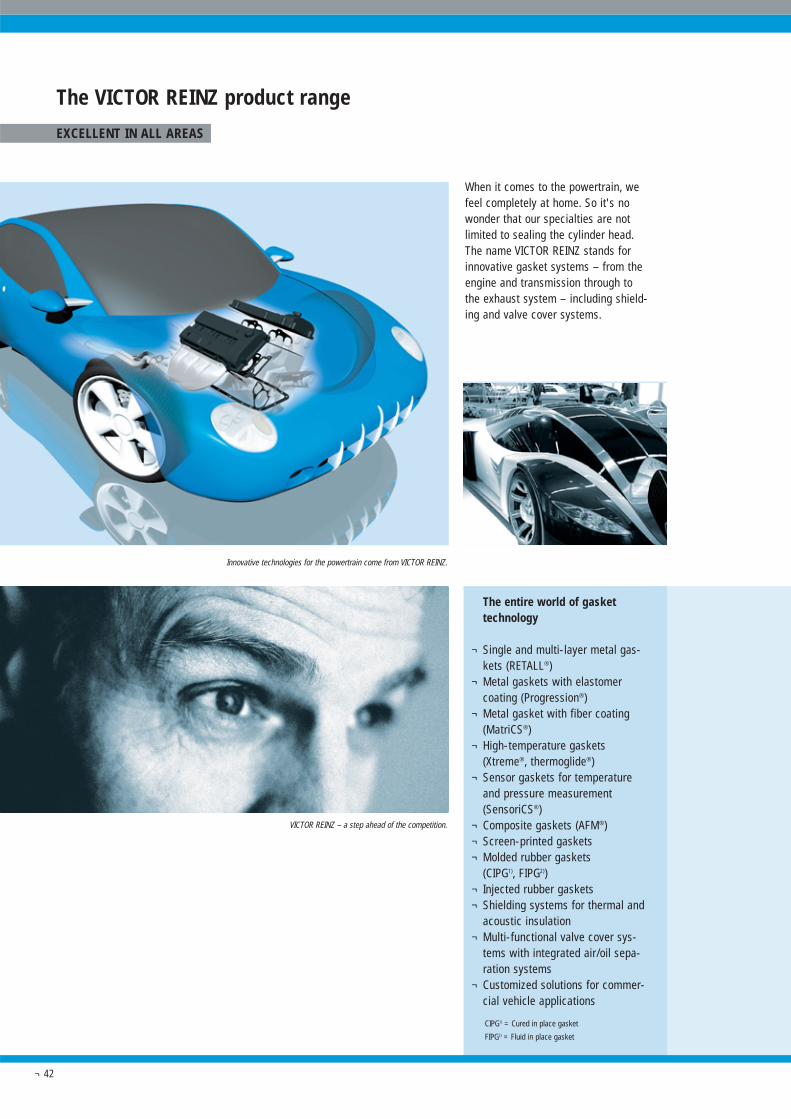
When it comes to the powertrain, wefeel completely at home. So it's nowonder that our specialties are notlimited to sealing the cylinder head.The name VICTOR REINZ stands forinnovative gasket systems – from theengine and transmission through to the exhaust system – including shield-ing and valve cover systems.
The entire world of gaskettechnology
¬ Single and multi-layer metal gas-kets (RETALL®)
¬ Metal gaskets with elastomercoating (Progression®)
¬ Metal gasket with fiber coating(MatriCS®)
¬ High-temperature gaskets(Xtreme®, thermoglide®)
¬ Sensor gaskets for temperatureand pressure measurement(SensoriCS®)
¬ Composite gaskets (AFM®)¬ Screen-printed gaskets¬ Molded rubber gaskets
(CIPG1), FIPG2))¬ Injected rubber gaskets¬ Shielding systems for thermal and
acoustic insulation¬ Multi-functional valve cover sys-
tems with integrated air/oil sepa-ration systems
¬ Customized solutions for commer-cial vehicle applications
Innovative technologies for the powertrain come from VICTOR REINZ.
VICTOR REINZ – a step ahead of the competition.
CIPG1) = Cured in place gasket
FIPG2) = Fluid in place gasket
¬ 43
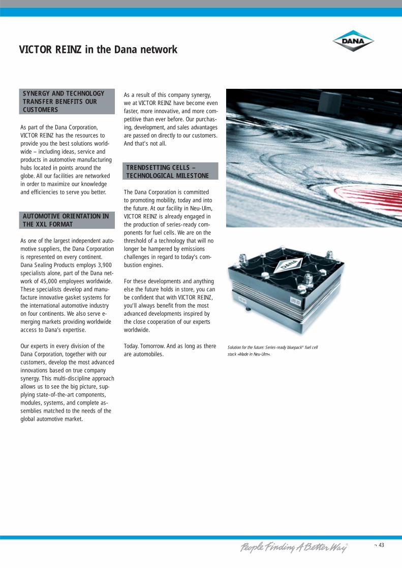
Solution for the future: Series-ready bluepack® fuel cell
stack »Made in Neu-Ulm«.
SYNERGY AND TECHNOLOGYTRANSFER BENEFITS OURCUSTOMERS
As part of the Dana Corporation,VICTOR REINZ has the resources toprovide you the best solutions world-wide – including ideas, service andproducts in automotive manufacturinghubs located in points around theglobe. All our facilities are networkedin order to maximize our knowledgeand efficiencies to serve you better.
AUTOMOTIVE ORIENTATION INTHE XXL FORMAT
As one of the largest independent auto-motive suppliers, the Dana Corporationis represented on every continent.Dana Sealing Products employs 3,900specialists alone, part of the Dana net-work of 45,000 employees worldwide.These specialists develop and manu-facture innovative gasket systems forthe international automotive industryon four continents. We also serve e-merging markets providing worldwideaccess to Dana’s expertise.
Our experts in every division of theDana Corporation, together with ourcustomers, develop the most advancedinnovations based on true companysynergy. This multi-discipline approachallows us to see the big picture, sup-plying state-of-the-art components,modules, systems, and complete as-semblies matched to the needs of theglobal automotive market.
As a result of this company synergy,we at VICTOR REINZ have become evenfaster, more innovative, and more com-petitive than ever before. Our purchas-ing, development, and sales advantagesare passed on directly to our customers.And that's not all.
TRENDSETTING CELLS –TECHNOLOGICAL MILESTONE
The Dana Corporation is committed to promoting mobility, today and intothe future. At our facility in Neu-Ulm,VICTOR REINZ is already engaged inthe production of series-ready com-ponents for fuel cells. We are on thethreshold of a technology that will nolonger be hampered by emissionschallenges in regard to today’s com-bustion engines.
For these developments and anythingelse the future holds in store, you canbe confident that with VICTOR REINZ,you’ll always benefit from the mostadvanced developments inspired bythe close cooperation of our expertsworldwide.
Today. Tomorrow. And as long as thereare automobiles.
VICTOR REINZ in the Dana network
REINZ-Dichtungs-GmbH
Reinzstraße 3-7
89233 Neu-Ulm
Deutschland
Phone +49 (0) 731-70 46-0
Fax +49 (0) 731-71 90 89
www.reinz.com
REINZ-Dichtungs-GmbH
Reinzstrasse 3-7
89233 Neu-Ulm
Germany
Phone +49 (0) 731-70 46-0
Fax +49 (0) 731-71 90 89
www.reinz.com
Prin
ted
in G
erm
any
01/0
5 · 3
9-00
185-
01