Embed Size (px)
Citation preview

ZXR10 8900 Series10G Routing Switch
User Manual (FW Volume)
Version 2.8.02.C
ZTE CORPORATIONZTE Plaza, Keji Road South,Hi-Tech Industrial Park,Nanshan District, Shenzhen,P. R. China518057Tel: (86) 755 26771900 800-9830-9830Fax: (86) 755 26772236URL: http://support.zte.com.cnE-mail: [email protected]
LEGAL INFORMATION
Copyright © 2006 ZTE CORPORATION.
The contents of this document are protected by copyright laws and international treaties. Any reproduction or distribution ofthis document or any portion of this document, in any form by any means, without the prior written consent of ZTE CORPO-RATION is prohibited. Additionally, the contents of this document are protected by contractual confidentiality obligations.
All company, brand and product names are trade or service marks, or registered trade or service marks, of ZTE CORPORATIONor of their respective owners.
This document is provided “as is”, and all express, implied, or statutory warranties, representations or conditions are dis-claimed, including without limitation any implied warranty of merchantability, fitness for a particular purpose, title or non-in-fringement. ZTE CORPORATION and its licensors shall not be liable for damages resulting from the use of or reliance on theinformation contained herein.
ZTE CORPORATION or its licensors may have current or pending intellectual property rights or applications covering the subjectmatter of this document. Except as expressly provided in any written license between ZTE CORPORATION and its licensee,the user of this document shall not acquire any license to the subject matter herein.
ZTE CORPORATION reserves the right to upgrade or make technical change to this product without further notice.
Users may visit ZTE technical support website http://ensupport.zte.com.cn to inquire related information.
The ultimate right to interpret this product resides in ZTE CORPORATION.
Revision History
Revision No. Revision Date Revision Reason
R1.0 20090630 First Release
Serial Number: sjzl20093843
Contents
About This Manual.............................................. i
Firewall Overview .............................................1Function Overview .......................................................... 1
Working Principle........................................................ 2
Working Modes........................................................... 4
Management Modes ........................................................ 5
Logging into FW through Console Port ........................... 5
Logging into FW through Telnet .................................... 6
Logging into FW through Browser ................................. 7
System Management Configuration ...................9System Management Overview......................................... 9
Querying System Basic Information .................................10
Querying System Running Information .............................10
Configuring System Management.....................................11
Setting System Parameters.........................................11
Managing System Services .........................................15
Setting Open Services ................................................16
Setting WEBUI Authentication .....................................20
Configuration Maintenance..............................................21
Configuration Maintenance Overview............................21
Configuring Maintenance ............................................22
Restoring System ......................................................23
Rebooting System .....................................................23
Configuring System Manager...........................................23
System Manager Overview..........................................23
Configuring System Manager.......................................23
System Manager Configuration Example .......................26
Resource Management Configuration ..............27Resource Management Overview .....................................27
Configuring Address Resource .........................................28
Address Resource Configuration Overview.....................28
Setting Host Resource ................................................28
Setting Address Range Resource..................................31
Setting Subnet Resource ............................................35
Setting Address Group ...............................................38
Configuring Area Resource..............................................41
Area Resource Configuration Overview .........................41
Configuring Area Resource..........................................41
Configuring Time Resource .............................................44
Time Resource Configuration Overview .........................44
Configuring Week Cycle ..............................................45
Configuring Year Cycle ...............................................47
Configuring Service Resource ..........................................50
Service Resource Configuration Overview......................50
Showing System Defined Services................................50
Configuring Customized Services .................................51
Configuring Server Group ...........................................54
ZXR10 FW Function Management ....................57ZXR10 FW Function Management Overview.......................57
Configuring ZXR10 FW ...................................................58
Accessing and Exiting FW Configuration Mode................58
Creating and Deleting FW-Template Mode .....................58
Binding Management IP..............................................59
Configuring Flow Recovery ..........................................60
Binding Slot Number ..................................................60
Configuring NAT IP ....................................................61
Configuring Session ...................................................62
Binding FW Template for Specific VLAN.........................62
Viewing Management Configuration..............................63
Configuring VLAN ......................................................64
Packet Filtering and Access Control Rule
Configuration............................................67Configuring Packet Filtering Policy....................................67
Packet Filtering Overview............................................67
Configuring Packet Filtering Policy................................67
Packet Filtering Policy Configuration Example ................73
Packet Filtering Policy Configuration Example
One .....................................................73
Packet Filtering Policy Configuration Example
Two......................................................75
Configuring Access Control Rules .....................................76
Access Control Rule Overview......................................76
Configuring Access Control Rule...................................76
Access Control Rule Configuration Example ...................82
Access Control Rule Configuration Example
One .....................................................82
Access Control Rule Configuration Example
Two......................................................84
Configuring IDS Interaction.............................................86
IDS Interaction Overview............................................86
Configuring IDS Interaction.........................................86
NAT Configuration ...........................................89NAT Overview ...............................................................89
Configuring NAT ............................................................90
NAT Configuration Example.............................................96
Address-Based Source Address Translation
Configuration Example .......................................96
IP Address-Based Destination Address Translation
Configuration Example .......................................97
Port-Based Destination Address Translation
Configuration Example .......................................98
Protocol Filtering Configuration.....................101Protocol Filtering Overview ........................................... 101
Configuring Application Port Binding............................... 101
Application Port Binding Overview.............................. 101
Configuring Application Port Binding........................... 102
Applying Port Binding Configuration Example............... 104
Configuring SIP Service ................................................ 104
Intrusion Prevention Configuration ...............107Intrusion Prevention Overview....................................... 107
Configuring Intrusion Detection Rule .............................. 107
Load Balancing Configuration........................113Load Balancing Overview.............................................. 113
Configuring Load Balancing........................................... 113
Configuring Load Balancing Server............................. 113
Configuring Load Balancing Group ............................. 116
High Availability Configuration Example .......................... 119
Log and Alarm Configuration .........................123Log and Alarm Overview............................................... 123
Log Configuration .................................................... 123
Viewing Log ............................................................ 123
Alarms ................................................................... 124
Configuring Logs and Alamrs......................................... 124
Configuring Log....................................................... 124
Viewing Log ............................................................ 126
Configuring Alarms .................................................. 127
Figures ..........................................................133
Tables ...........................................................135
Glossary ........................................................137
About This Manual
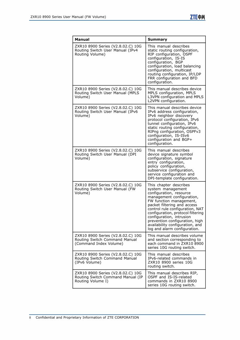
This manual is ZXR10 8900 Series (V2.8.02.C) 10G Rout-ing Switch User Manual (FW Volume) and applies to ZXR108902/8905/8908/8912 10G routing switch (V2.8.02.C).
ZXR10 8900 series 10G routing switch has the following relatedmanuals:
Manual Summary
ZXR10 8900 Series (V2.8.02.C) 10GRouting Switch Hardware InstallationManual
This manual describesinstallation preparation,19-inch cabinet installation,main device installation,power cable connection, cableconnection and hardwareinspection.
ZXR10 8900 Series (V2.8.02.C) 10GRouting Switch Hardware Manual
This manual describesdevice functions, technicalcharacteristics andparameters, working principle,hardware structure, MCS, LIC,power module and fan plug-inbox.
ZXR10 8900 Series (V2.8.02.C) 10GRouting Switch User Manual (BasicConfiguration Volume)
This manual describes usingand operation of device,system management,CLI privilege rankingconfiguration, portconfiguration, networkprotocol configuration,DHCP configuration,VRRP configuration,ACL configuration, QoSconfiguration, DOTIXconfiguration, clustermanagement configuration,network managementconfiguration, IPTVconfiguration, VBASconfiguration, CPU guard,URPF configuration and UDLDconfiguration.
ZXR10 8900 Series (V2.8.02.C) 10GRouting Switch User Manual (EthernetSwitching Volume)
This manual describesdevice VLAN configuration,STP configuration, MACaddress table operation, linkaggregation configuration,IGMP Snooping configuration,link protection configuration,Ethernet OAM configurationand EPON OLT configuration.
Confidential and Proprietary Information of ZTE CORPORATION i
ZXR10 8900 Series User Manual (FW Volume)
Manual Summary
ZXR10 8900 Series (V2.8.02.C) 10GRouting Switch User Manual (IPv4Routing Volume)
This manual describesstatic routing configuration,RIP configuration, OSPFconfiguration, IS-ISconfiguration, BGPconfiguration, load balancingconfiguration, multicastrouting configuration, IP/LDPFRR configuration and BFDconfiguration.
ZXR10 8900 Series (V2.8.02.C) 10GRouting Switch User Manual (MPLSVolume)
This manual describes deviceMPLS configuration, MPLSL3VPN configuration and MPLSL2VPN configuration.
ZXR10 8900 Series (V2.8.02.C) 10GRouting Switch User Manual (IPv6Volume)
This manual describes deviceIPv6 address configuration,IPv6 neighbor discoveryprotocol configuration, IPv6tunnel configuration, IPv6static routing configuration,RIPng configuration, OSPFv3configuration, IS-ISv6configuration and BGP+configuration.
ZXR10 8900 Series (V2.8.02.C) 10GRouting Switch User Manual (DPIVolume)
This manual describesdevice signature symbolconfiguration, signatureentry configuration,policy configuration,subservice configuration,service configuration andDPI-template configuration.
ZXR10 8900 Series (V2.8.02.C) 10GRouting Switch User Manual (FWVolume)
This chapter describessystem managementconfiguration, resourcemanagement configuration,FW function management,packet filtering and accesscontrol rule configuration, NATconfiguration, protocol filteringconfiguration, intrusionprevention configuration, highavailability configuration, andlog and alarm configuration.
ZXR10 8900 Series (V2.8.02.C) 10GRouting Switch Command Manual(Command Index Volume)
This manual describes volumeand section corresponding toeach command in ZXR10 8900series 10G routing switch.
ZXR10 8900 Series (V2.8.02.C) 10GRouting Switch Command Manual(IPv6 Volume)
This manual describesIPv6-related commands inZXR10 8900 series 10Grouting switch.
ZXR10 8900 Series (V2.8.02.C) 10GRouting Switch Command Manual (IPRouting Volume I)
This manual describes RIP,OSPF and IS-IS-relatedcommands in ZXR10 8900series 10G routing switch.
ii Confidential and Proprietary Information of ZTE CORPORATION
About This Manual
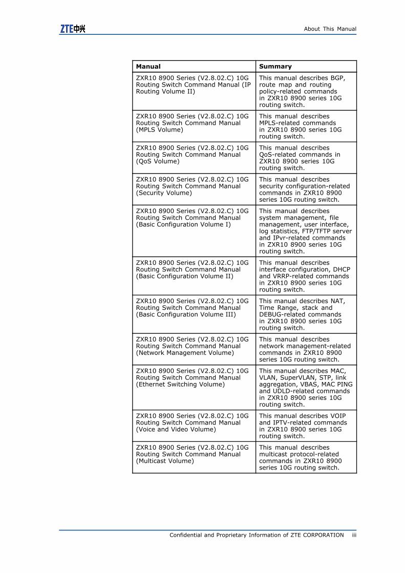
Manual Summary
ZXR10 8900 Series (V2.8.02.C) 10GRouting Switch Command Manual (IPRouting Volume II)
This manual describes BGP,route map and routingpolicy-related commandsin ZXR10 8900 series 10Grouting switch.
ZXR10 8900 Series (V2.8.02.C) 10GRouting Switch Command Manual(MPLS Volume)
This manual describesMPLS-related commandsin ZXR10 8900 series 10Grouting switch.
ZXR10 8900 Series (V2.8.02.C) 10GRouting Switch Command Manual(QoS Volume)
This manual describesQoS-related commands inZXR10 8900 series 10Grouting switch.
ZXR10 8900 Series (V2.8.02.C) 10GRouting Switch Command Manual(Security Volume)
This manual describessecurity configuration-relatedcommands in ZXR10 8900series 10G routing switch.
ZXR10 8900 Series (V2.8.02.C) 10GRouting Switch Command Manual(Basic Configuration Volume I)
This manual describessystem management, filemanagement, user interface,log statistics, FTP/TFTP serverand IPvr-related commandsin ZXR10 8900 series 10Grouting switch.
ZXR10 8900 Series (V2.8.02.C) 10GRouting Switch Command Manual(Basic Configuration Volume II)
This manual describesinterface configuration, DHCPand VRRP-related commandsin ZXR10 8900 series 10Grouting switch.
ZXR10 8900 Series (V2.8.02.C) 10GRouting Switch Command Manual(Basic Configuration Volume III)
This manual describes NAT,Time Range, stack andDEBUG-related commandsin ZXR10 8900 series 10Grouting switch.
ZXR10 8900 Series (V2.8.02.C) 10GRouting Switch Command Manual(Network Management Volume)
This manual describesnetwork management-relatedcommands in ZXR10 8900series 10G routing switch.
ZXR10 8900 Series (V2.8.02.C) 10GRouting Switch Command Manual(Ethernet Switching Volume)
This manual describes MAC,VLAN, SuperVLAN, STP, linkaggregation, VBAS, MAC PINGand UDLD-related commandsin ZXR10 8900 series 10Grouting switch.
ZXR10 8900 Series (V2.8.02.C) 10GRouting Switch Command Manual(Voice and Video Volume)
This manual describes VOIPand IPTV-related commandsin ZXR10 8900 series 10Grouting switch.
ZXR10 8900 Series (V2.8.02.C) 10GRouting Switch Command Manual(Multicast Volume)
This manual describesmulticast protocol-relatedcommands in ZXR10 8900series 10G routing switch.
Confidential and Proprietary Information of ZTE CORPORATION iii
ZXR10 8900 Series User Manual (FW Volume)
Manual Summary
ZXR10 8900 Series (V2.8.02.C) 10GRouting Switch Command Manual(DPI Volume)
This manual describesDPI-related commands inZXR10 8900 series 10Grouting switch.
ZXR10 8900 Series (V2.8.02.C) 10GRouting Switch Command Manual(FW Volume)
This manual describesFW-related commands inZXR10 8900 series 10Grouting switch.
Commands supported by ZXR10 8900 series (V2.8.02.C) 10Grouting switch are based on uniform platform ZXROS V4.8.22.
ZXR10 8900 Series (V2.8.02.C) 10G Routing Switch User Manual(FW Volume) contains the following chapters:
Chapter Summary
Chapter 1 FW Overview This chapter describes FW functional principleand management mode.
Chapter 2 SystemManagementConfiguration
This chapter describes basic concept,configuration and configuration example ofFW system management.
Chapter 3 ResourceManagementConfiguration
This chapter describes basic concept,configuration and configuration example ofFW resource management.
Chapter 4 ZXR10 FWFunction Management
This chapter describes basic concept,configuration and configuration example ofFW function management.
Chapter 5 PacketFiltering andAccess Control RuleConfiguration
This chapter describes basic concepts,configurations and configuration examples ofFW packet filtering and access control rule.
Chapter 6 NATConfiguration
This chapter describes basic concept,configuration and configuration example ofFW NAT.
Chapter 7 ProtocolFiltering Configuration
This chapter describes basic concept,configuration and configuration example ofFW protocol filtering.
Chapter 8 IntrusionPrevensionConfiguration
This chapter describes basic concept,configuration and configuration example ofFW intrusion prevention.
Chapter 9 High Availability Configuration
This chapter describes basic concept,configuration and configuration example ofFW high availability.
Chapter 10 Log andAlarm Configuration
This chapter describes basic concept,configuration and configuration example oflog and alarm.
Glossary This part lists glossaries used in this manual.
iv Confidential and Proprietary Information of ZTE CORPORATION
C h a p t e r 1
Firewall Overview
Table of Contents:Function Overview .............................................................. 1Management Modes ............................................................ 5
Function OverviewZXR10 8900 Series Switch firewall (FW) service card has the fol-lowing basic functions:
� Supporting routing and hybrid working modes;
� Supporting object-based network access control, including ac-cess control of network layer, application layer and other lay-ers;
� Supporting NAT of multiple types of network addresses;
� Supporting built-in IDS module, which prevents Land, Smurf,TearOfDrop, Ping of Death, SynFlood, Targa3, IpSweep andanother few attacks and has the function of anti-DOS/DDOS.
� Supporting hot standby between FW cards;
� Supporting FTP, TFTP, MMS, H.323, SIP, RSTP, SQLNET, andPPTP protocols.
ZXR10 8900 Series Switch FW has the following features:
� Adopting the design of multi-interfaces, providing sound net-work application scalability.
� Providing high-efficiency application layer access control.Proxy technology is used for traditional access control onapplication layer. System needs to switch among core layer,application layer and processes frequently, which consumes alot system resources and influences performance.
� Showing flexible management. Network administrator can ac-cess FW through various interfaces for central management.
� Using a brand new management port protocol. With this pro-tocol, multiple management services can be enabled on theunique service interface of FW.
� Providing high-performance content filtering. Core layer ofsystem provides restore and security inspection to transmit-ted packets and implements high-performance content secu-rity protocol.
Confidential and Proprietary Information of ZTE CORPORATION 1
ZXR10 8900 Series User Manual (FW Volume)
Working Principle
Data FlowProcessing Flow
Generally, FW is used to control access from external untrustednetworks (such as Internet) to internal trusted networks and mu-tual accesses among different areas within internal network. OSplatform used by ZXR10 8900 Series Switch FW is the latest mod-ular OS. By uploading a series of functional modules such as FWmodule and packet filtering module, FW module can control dataflow traversing security device by setting access rules, packet fil-tering rules, interface properties and other mechanisms. ZXR108900 Series Switch FW takes the following basic steps to processpackets:
1. Fast Forwarding
As for a newly received legal packet, FW firstly searches ses-sion table to see if this packet has belonged to one existed ses-sion. If so, FW processes this packet according to correspond-ing session in the session table. When the packet matchesaccess rule and address translation policy of this session, FWprocesses this packet fast. If the session is unavailable, it indi-cates this packet belongs to one new session. FW will retrieverouting table, address translation policy table and access ruletable to collect policies related to this packet, that is entering"Receiving and Processing" flow.
2. Receiving and Processing
ZXR10 8900 Series Switch FW module invokes related func-tional module and conducts initial processing to received pack-ets. The following functional modules are invoked:
� IDS Module, used to perform intrusion detection to pack-ets. If the received packet matches IDS rule, it is regardedillegal and dropped.
� IP-MAC binding module. If IP address and MAC addressdata contained in header of received packet break rules inIP-MAC binding table, the packet will be dropped.
3. Rule Matching
At this step, FW matches the packet passing through receivingand processing step with a series of rules. The following mod-ules are invoked:
� PF module. PF module not only conducts L2/L3 protocolfiltering to the packet, but also checks if the packet belongsto the service that can pass through.
� Address translation module. Address translation policygives processing method of received packet. ZXR10 8900Series Switch FW module supports four address translationpolicies:
– Forwarding directly
FW doesn’t process packet and the packet is forwardeddirectly. This is default address translation policy ofZXR10 8900 Series Switch FW.
– Translating source address
2 Confidential and Proprietary Information of ZTE CORPORATION
Chapter 1 Firewall Overview
FW translates source IP address (or port id) of the re-ceived packet to preset IP address (or port id), and thenforwards the packet whose source address is modified.
– Translating destination address
FW translates destination IP address or port id of thereceived packet (FW interface address in usual cases)to preset IP address or port id (actual IP address or portid), and then forwards the packet whose destinationaddress is modified.
– Bi-directional NAT
FW translates source address and destination address(or port id) of the packet at the same time.
� Access control module. Access control rule defines if FWpermits the packets matching rules to pass through. Whenreceiving one packet, FW matches it with rules in accessrule table one by one according to policy sequence num-ber and processes the packet according to operation (per-mit or deny) specified by corresponding policy. If corre-sponding access policy fails to be matched, the packet willbe forwarded to destination interface. ZXR10 8900 SeriesSwitchFW will proces this packet according to default prop-erty (permit or deny) of the area where destination inter-face locates.
4. Session Establishment
As for the packet with no session for matching, ZXR10 8900Series SwitchFW will create one new record in session table ac-cording to packet processing information in steps 1-3, includ-ing packet destination address, source address, route, addresstranslation policy, access rule and other information. Packetsof this session received after this new record will be processedaccording to record in the session table.
5. Processing before Routing
When policy changes during communication process, FW willre-invoke packet filtering module and access control moduleto match the packet with policy.
6. Route Querying
ZXR10 8900 Series SwitchFW module selects packet forward-ing interface according to routing table or MAC address tablelearned on each interface. If packet address is translated, FWwill search NAT table to find the actual address for routing.
Matching AccessControl Rules
Access control rules are a set of policies customized by user. Theserules can define what packets (meeting certain conditions) canpass FW and what packets (meeting some other conditions) will bedenied by FW. Data contained in each access policy include: sourceaddress and destination address of the packet, service (protocoltype and port id) and operations (forwarding or dropping) per-formed to the packets meeting conditions.
In access policy, policy source defines the source of packet, whichcan be one or multiple objects (such as host, subnet, scope and soon). When source address of the packet belongs to the scope ofpolicy source, it is believed to meet constraint conditions of policysource.
Confidential and Proprietary Information of ZTE CORPORATION 3
ZXR10 8900 Series User Manual (FW Volume)
Policy destination defines the scope of destination address. Thesame as policy source, policy destination can contain one or mul-tiple hosts, subnet, scope and multiple areas (or VLAN).
Policy service defines network protocol used by packet and specificport id.
Access control defines FW operations to the packet meeting poli-cies, including permit (permit the packet to pass through) anddeny (drop this packet).
In the case that a packet matches one access policy, it indicatessource address of the packet is within the scope defined by pol-icy source, destination address of the packet is within the scopedefined by policy destination, port id corresponding to the packetis contained in policy service, and packet receiving time meet therequirement of policy access time (if access time is defined). Onlywhen one packet meets all conditions required by the policy, thispolicy matches this packet.
It shall be noted that one content filtering policy and one appli-cation identity policy shall be defined for each access rule to filterand inspect data at application layer. FW searches the access pol-icy matching a packet according at the following steps:
ZXR10 8900 Series Switch FW module retrieves access control ruletable according to sequence of access policies and matches poli-cies with packet one by one. Once an access policy is found tomatch the packet, FW stops checking matched access policy andprocesses the packet (permit or deny) according to rules definedin the first matched access policy. If no access policy is found tomatch this packet, FW will process this packet according to defaultaccess control properties on packet sending interface.
If the packet is forbidden to be forwarded, it will be dropped; if thepacket is permitted to be forwarded, check if this policy defines DPIpolicy or application identity policy.
If application identity policy is defined in the policy, check to see ifany protocol of the application identity policy is used in applicationlayer of the packet. If corresponding protocol is used, process thispacket according to operations defined by this application identitypolicy.
Working Modes
ZXR10 8900 Series Switch FW protects VLAN interfaces and sup-ports two working modes: routing mode and hybrid mode.
Route Mode In this mode, ZXR10 8900 Series Switch FW protects L3 packets onprotected vlan interface. All L3 packets passing through protectedvlan are forwarded only after being processed by FW module. Thismode is applicable to the case when each area is in a separatenetwork segment. Similar to router, IP address shall be configuredfor each vlan interface in routing mode or hybrid mode accordingto area planning.
Hybrid Mode In this mode, ZXR10 8900 Series Switch FW protects L2 and L3packets on protected vlan interface. No matter internal L2 packetsof the protected vlan or L3 packets cross-vlans are forwarded afterbeing processed by FW module.
4 Confidential and Proprietary Information of ZTE CORPORATION
Chapter 1 Firewall Overview
Management ModesNetwork administrator can manage ZXR10 8900 Series Switch FWmodule in many ways, including:
� Through CONSOLE (perform local management through CON-SOLE port)
� Through TELNET (perform remote management by logging intoFW through Telnet)
� Through WEBUI (perform remote management by logging intoFW through browser)
Logging into FW through ConsolePort
Context It is available to log into FW module through CONSOLE port andconduct some basic settings on FW.
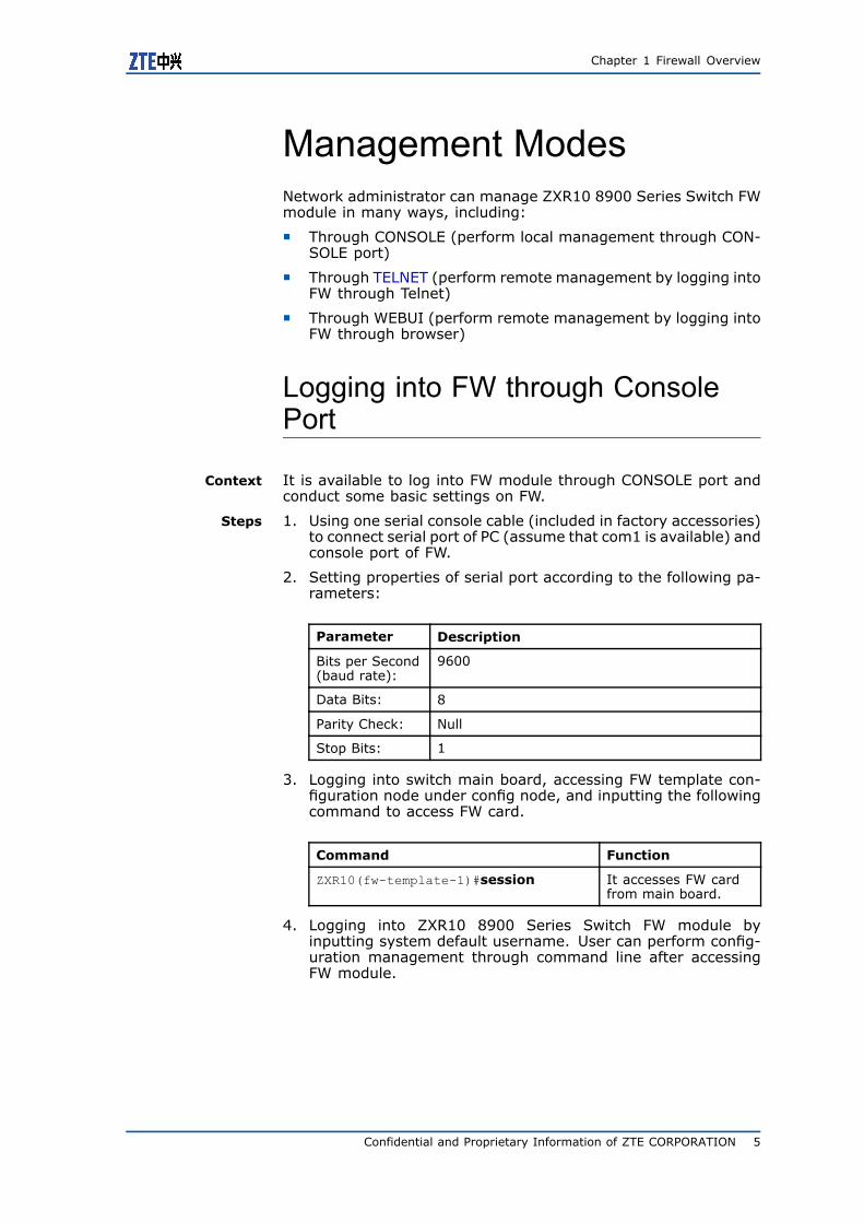
Steps 1. Using one serial console cable (included in factory accessories)to connect serial port of PC (assume that com1 is available) andconsole port of FW.
2. Setting properties of serial port according to the following pa-rameters:
Parameter Description
Bits per Second(baud rate):
9600
Data Bits: 8
Parity Check: Null
Stop Bits: 1
3. Logging into switch main board, accessing FW template con-figuration node under config node, and inputting the followingcommand to access FW card.
Command Function
ZXR10(fw-template-1)#session It accesses FW cardfrom main board.
4. Logging into ZXR10 8900 Series Switch FW module byinputting system default username. User can perform config-uration management through command line after accessingFW module.
Confidential and Proprietary Information of ZTE CORPORATION 5
ZXR10 8900 Series User Manual (FW Volume)
Tip:
Both username and password are case sensitive.
END OF STEPS.
Logging into FW through Telnet
Context It is available to log into FW module through Telnet and conductsome basic settings on FW.
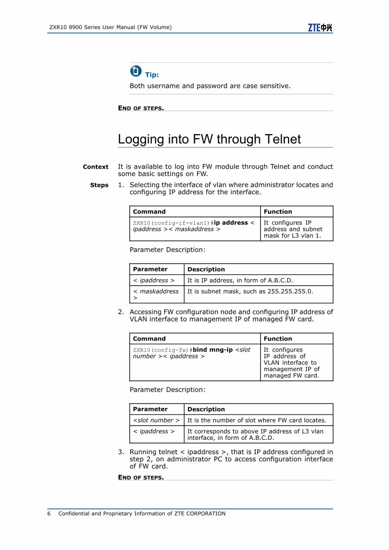
Steps 1. Selecting the interface of vlan where administrator locates andconfiguring IP address for the interface.
Command Function
ZXR10(config-if-vlan1)#ip address <ipaddress >< maskaddress >
It configures IPaddress and subnetmask for L3 vlan 1.
Parameter Description:
Parameter Description
< ipaddress > It is IP address, in form of A.B.C.D.
< maskaddress>
It is subnet mask, such as 255.255.255.0.
2. Accessing FW configuration node and configuring IP address ofVLAN interface to management IP of managed FW card.
Command Function
ZXR10(config-fw)#bind mng-ip <slotnumber >< ipaddress >
It configuresIP address ofVLAN interface tomanagement IP ofmanaged FW card.
Parameter Description:
Parameter Description
<slot number > It is the number of slot where FW card locates.
< ipaddress > It corresponds to above IP address of L3 vlaninterface, in form of A.B.C.D.
3. Running telnet < ipaddress >, that is IP address configured instep 2, on administrator PC to access configuration interfaceof FW card.
END OF STEPS.
6 Confidential and Proprietary Information of ZTE CORPORATION
Chapter 1 Firewall Overview
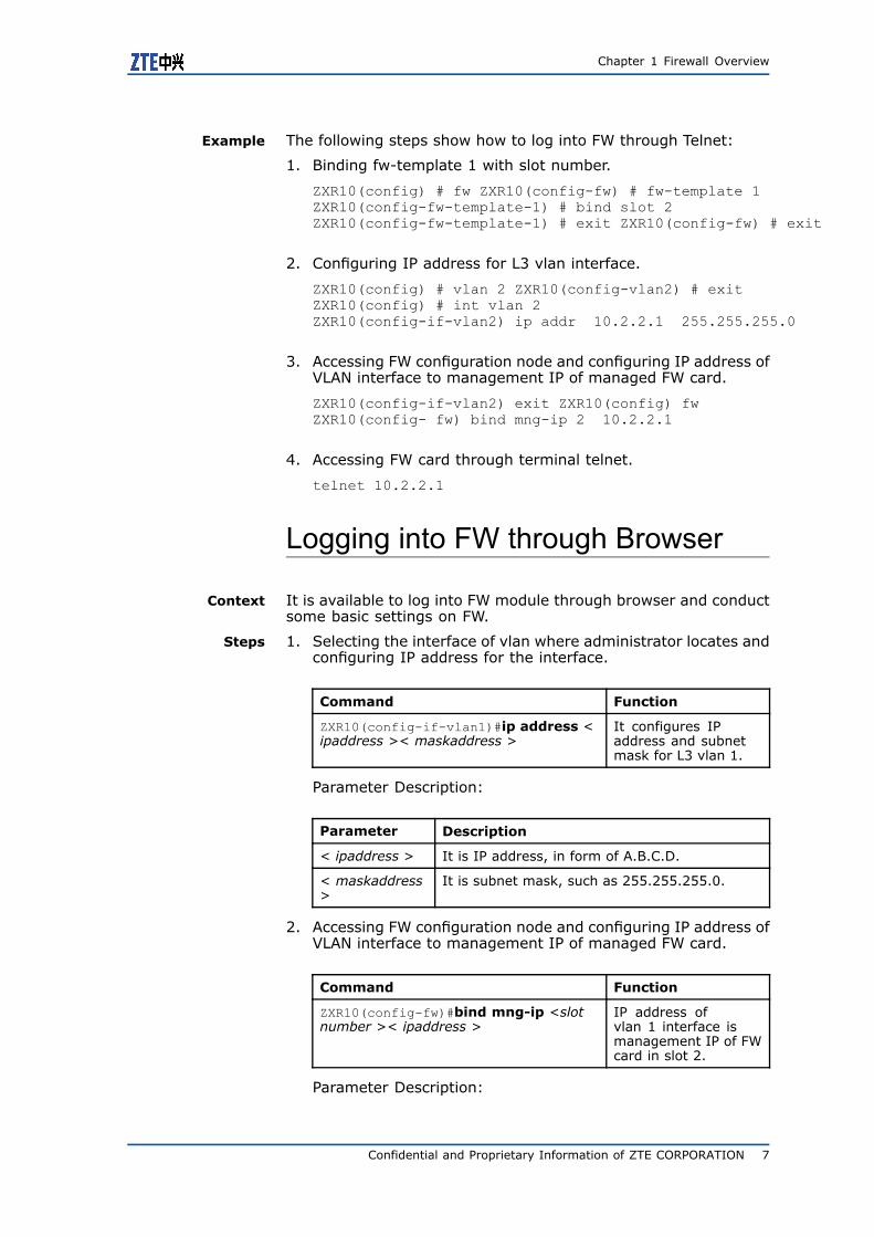
Example The following steps show how to log into FW through Telnet:
1. Binding fw-template 1 with slot number.
ZXR10(config) # fw ZXR10(config-fw) # fw-template 1ZXR10(config-fw-template-1) # bind slot 2ZXR10(config-fw-template-1) # exit ZXR10(config-fw) # exit
2. Configuring IP address for L3 vlan interface.
ZXR10(config) # vlan 2 ZXR10(config-vlan2) # exitZXR10(config) # int vlan 2ZXR10(config-if-vlan2) ip addr 10.2.2.1 255.255.255.0
3. Accessing FW configuration node and configuring IP address ofVLAN interface to management IP of managed FW card.
ZXR10(config-if-vlan2) exit ZXR10(config) fwZXR10(config- fw) bind mng-ip 2 10.2.2.1
4. Accessing FW card through terminal telnet.
telnet 10.2.2.1
Logging into FW through Browser
Context It is available to log into FW module through browser and conductsome basic settings on FW.
Steps 1. Selecting the interface of vlan where administrator locates andconfiguring IP address for the interface.
Command Function
ZXR10(config-if-vlan1)#ip address <ipaddress >< maskaddress >
It configures IPaddress and subnetmask for L3 vlan 1.
Parameter Description:
Parameter Description
< ipaddress > It is IP address, in form of A.B.C.D.
< maskaddress>
It is subnet mask, such as 255.255.255.0.
2. Accessing FW configuration node and configuring IP address ofVLAN interface to management IP of managed FW card.
Command Function
ZXR10(config-fw)#bind mng-ip <slotnumber >< ipaddress >
IP address ofvlan 1 interface ismanagement IP of FWcard in slot 2.
Parameter Description:
Confidential and Proprietary Information of ZTE CORPORATION 7
ZXR10 8900 Series User Manual (FW Volume)
Parameter Description
<slot number > It is the number of slot where FW card locates.
< ipaddress > It is IP address, in form of A.B.C.D.
3. Administrator inputs FW management URL (such as https://<ipaddress >) on browser of management host and login inter-face pops up.
END OF STEPS.
Example The following steps show how to log in FW through browser https.
1. Binding fw-template 1 with slot number.
ZXR10(config) # fw ZXR10(config-fw) # fw-template 1ZXR10(config-fw-template1) # bind slot 2
2. Configuring IP address for L3 vlan interface.
ZXR10(config) # vlan 2 ZXR10(config-vlan2) # exitZXR10(config) # int vlan 2 ZXR10(config-if-vlan2) ip addr10.2.2.1 255.255.255.0
3. Accessing FW configuration node and configuring IP address ofVLAN interface to management IP of managed FW card.
ZXR10(config-if-vlan2) exit ZXR10(config) fwZXR10(config- fw) bind mng-ip 2 10.2.2.1
4. Logging in FW card through https.
https :// 10.2.2.1
8 Confidential and Proprietary Information of ZTE CORPORATION
C h a p t e r 2
System ManagementConfiguration
Table of Contents:System Management Overview............................................. 9Querying System Basic Information .....................................10Querying System Running Information .................................10Configuring System Management.........................................11Configuration Maintenance..................................................21Configuring System Manager...............................................23
System ManagementOverviewIn system command module, user can configure basic informa-tion of ZXR10 8900 Series Switch FW service card, such as ver-sion display, clock management, NTP setting, system configurationmanagement, system upgrade, authentication user management,administrator information, FW reboot command and so on.
To access command module, execute the following command:
#system
To exit from this command module, execute the following com-mand:
#exit
After logging into FW and accessing this command module, CLIadministrator can execute corresponding component managementcommands. The following parts will introduce all component man-agement commands under this command module. The format ofcommand in the example is that after accessing this commandmodule.
Confidential and Proprietary Information of ZTE CORPORATION 9
ZXR10 8900 Series User Manual (FW Volume)
Querying System BasicInformationUser can search model, software platform version, system currentconfiguration and other information of current device in systemcommand module.
1. Displaying system version information
Command Function
ZXR10_FW.system #version It displays systemversion information.
2. Displaying running statuses of system services
Command Function
ZXR10_FW.system #service status It displays runningstatuses of systemservices (such asserver state and ifvarious services areenabled).
3. Displaying system name
Command Function
ZXR10_FW.system #devname show It displays systemname.
4. Displaying current configuration of system
Command Function
ZXR10_FW.system #config show_running
It displays currentconfiguration ofsystem.
Querying System RunningInformationRunning information indicates current system CPU, memory, otheroccupation information of system resources, and connection infor-mation established through FW.
1. Viewing current running status of device.
10 Confidential and Proprietary Information of ZTE CORPORATION
Chapter 2 System Management Configuration
Command Function
ZXR10_FW.system #information It views currentrunning status ofdevice, includingmemory information,CPU utilization andother information.
2. Showing network connection information.
Command Function
ZXR10_FW.system #netstat It shows networkconnection, routingtable and networkinterface information,and thus user canlearn which networkconnections are beingused currently.
Configuring SystemManagementSetting System Parameters
User can set administrator login parameter and connection time-out parameter, and view session statistics on authset commandmodule. System parameter specifies the max login failures forthe same one administrator and concurrent administrators, andmanaging login site. Once the login failure number of an admin-istrator exceeds threshold, system will lock the login to preventillegal users logging into ZXR10 8900 Series Switch FW servicecard through brute force of password.
To access authset command module, execute the following com-mand:
#authset
To exit from this command module, execute the following com-mand:
#exit
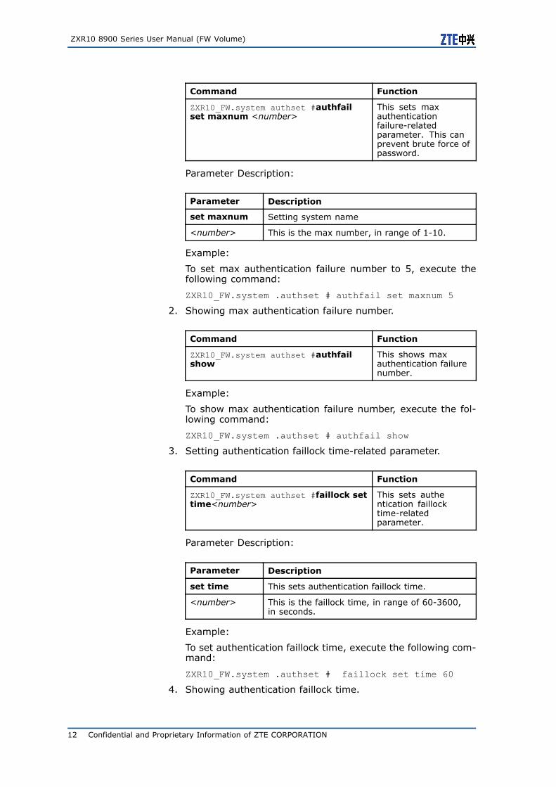
1. Setting max authentication failure-related parameter.
Confidential and Proprietary Information of ZTE CORPORATION 11
ZXR10 8900 Series User Manual (FW Volume)
Command Function
ZXR10_FW.system authset #authfailset maxnum <number>
This sets maxauthenticationfailure-relatedparameter. This canprevent brute force ofpassword.
Parameter Description:
Parameter Description
set maxnum Setting system name
<number> This is the max number, in range of 1-10.
Example:
To set max authentication failure number to 5, execute thefollowing command:
ZXR10_FW.system .authset # authfail set maxnum 5
2. Showing max authentication failure number.
Command Function
ZXR10_FW.system authset #authfailshow
This shows maxauthentication failurenumber.
Example:
To show max authentication failure number, execute the fol-lowing command:
ZXR10_FW.system .authset # authfail show
3. Setting authentication faillock time-related parameter.
Command Function
ZXR10_FW.system authset #faillock settime<number>
This sets authentication faillocktime-relatedparameter.
Parameter Description:
Parameter Description
set time This sets authentication faillock time.
<number> This is the faillock time, in range of 60-3600,in seconds.
Example:
To set authentication faillock time, execute the following com-mand:
ZXR10_FW.system .authset # faillock set time 60
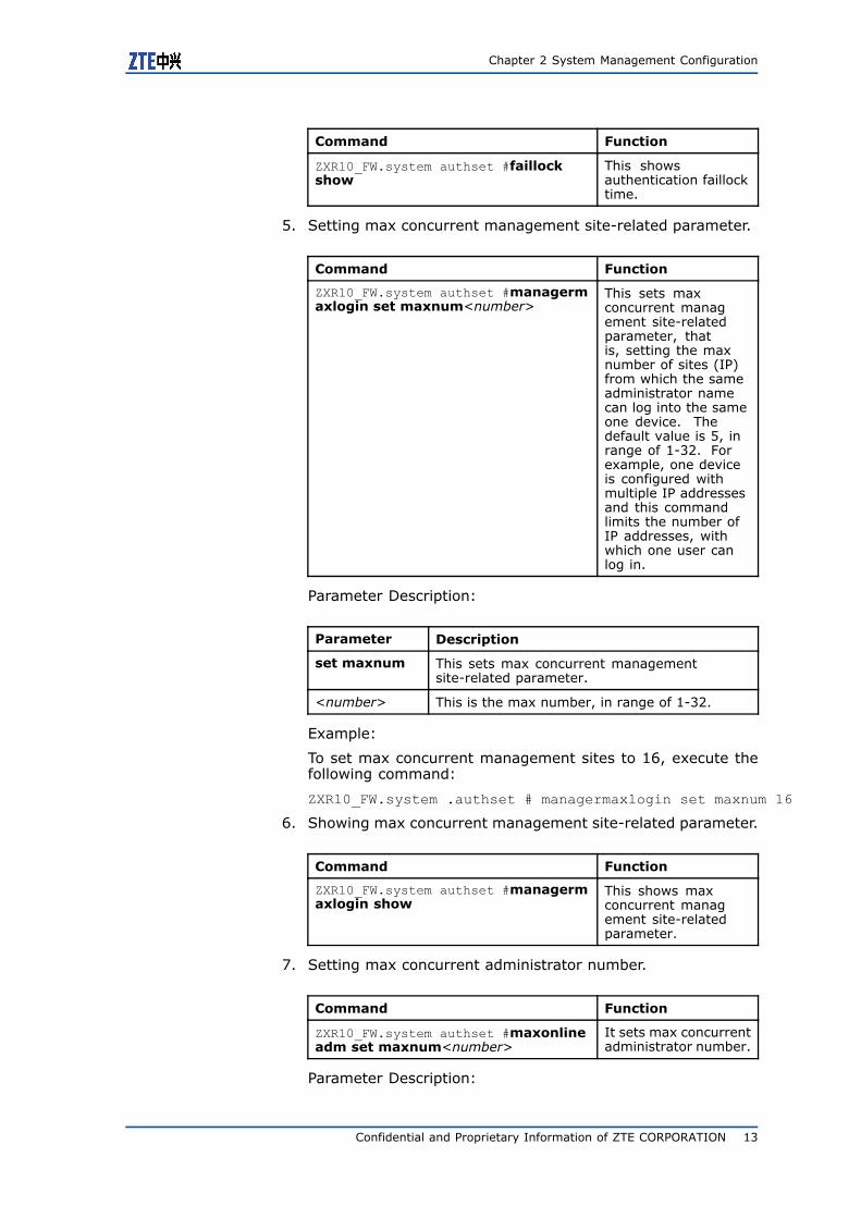
4. Showing authentication faillock time.
12 Confidential and Proprietary Information of ZTE CORPORATION
Chapter 2 System Management Configuration
Command Function
ZXR10_FW.system authset #faillockshow
This showsauthentication faillocktime.
5. Setting max concurrent management site-related parameter.
Command Function
ZXR10_FW.system authset #managermaxlogin set maxnum<number>
This sets maxconcurrent management site-relatedparameter, thatis, setting the maxnumber of sites (IP)from which the sameadministrator namecan log into the sameone device. Thedefault value is 5, inrange of 1-32. Forexample, one deviceis configured withmultiple IP addressesand this commandlimits the number ofIP addresses, withwhich one user canlog in.
Parameter Description:
Parameter Description
set maxnum This sets max concurrent managementsite-related parameter.
<number> This is the max number, in range of 1-32.
Example:
To set max concurrent management sites to 16, execute thefollowing command:
ZXR10_FW.system .authset # managermaxlogin set maxnum 16
6. Showing max concurrent management site-related parameter.
Command Function
ZXR10_FW.system authset #managermaxlogin show
This shows maxconcurrent management site-relatedparameter.
7. Setting max concurrent administrator number.
Command Function
ZXR10_FW.system authset #maxonlineadm set maxnum<number>
It sets max concurrentadministrator number.
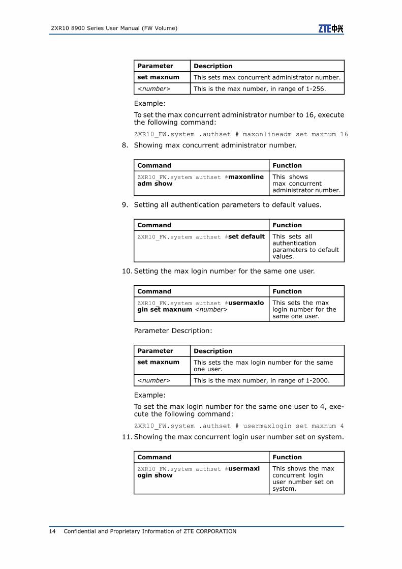
Parameter Description:
Confidential and Proprietary Information of ZTE CORPORATION 13
ZXR10 8900 Series User Manual (FW Volume)
Parameter Description
set maxnum This sets max concurrent administrator number.
<number> This is the max number, in range of 1-256.
Example:
To set the max concurrent administrator number to 16, executethe following command:
ZXR10_FW.system .authset # maxonlineadm set maxnum 16
8. Showing max concurrent administrator number.
Command Function
ZXR10_FW.system authset #maxonlineadm show
This showsmax concurrentadministrator number.
9. Setting all authentication parameters to default values.
Command Function
ZXR10_FW.system authset #set default This sets allauthenticationparameters to defaultvalues.
10.Setting the max login number for the same one user.
Command Function
ZXR10_FW.system authset #usermaxlogin set maxnum <number>
This sets the maxlogin number for thesame one user.
Parameter Description:
Parameter Description
set maxnum This sets the max login number for the sameone user.
<number> This is the max number, in range of 1-2000.
Example:
To set the max login number for the same one user to 4, exe-cute the following command:
ZXR10_FW.system .authset # usermaxlogin set maxnum 4
11.Showing the max concurrent login user number set on system.
Command Function
ZXR10_FW.system authset #usermaxlogin show
This shows the maxconcurrent loginuser number set onsystem.
14 Confidential and Proprietary Information of ZTE CORPORATION
Chapter 2 System Management Configuration
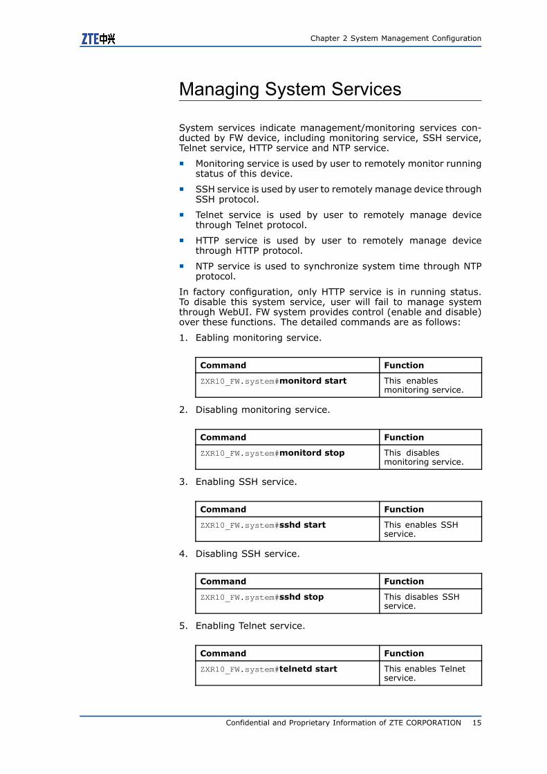
Managing System Services
System services indicate management/monitoring services con-ducted by FW device, including monitoring service, SSH service,Telnet service, HTTP service and NTP service.
� Monitoring service is used by user to remotely monitor runningstatus of this device.
� SSH service is used by user to remotely manage device throughSSH protocol.
� Telnet service is used by user to remotely manage devicethrough Telnet protocol.
� HTTP service is used by user to remotely manage devicethrough HTTP protocol.
� NTP service is used to synchronize system time through NTPprotocol.
In factory configuration, only HTTP service is in running status.To disable this system service, user will fail to manage systemthrough WebUI. FW system provides control (enable and disable)over these functions. The detailed commands are as follows:
1. Eabling monitoring service.
Command Function
ZXR10_FW.system#monitord start This enablesmonitoring service.
2. Disabling monitoring service.
Command Function
ZXR10_FW.system#monitord stop This disablesmonitoring service.
3. Enabling SSH service.
Command Function
ZXR10_FW.system#sshd start This enables SSHservice.
4. Disabling SSH service.
Command Function
ZXR10_FW.system#sshd stop This disables SSHservice.
5. Enabling Telnet service.
Command Function
ZXR10_FW.system#telnetd start This enables Telnetservice.
Confidential and Proprietary Information of ZTE CORPORATION 15
ZXR10 8900 Series User Manual (FW Volume)
6. Disabling Telnet service.
Command Function
ZXR10_FW.system#telnetd stop This disables Telnetservice.
7. Enabling HTTP service.
Command Function
ZXR10_FW.system#httpd start This enables HTTPservice.
8. Disabling HTTP service.
Command Function
ZXR10_FW.system#httpd stop This disables HTTPservice.
Note:
When enabling corresponding system service, system will enablecorresponding service program on background to provide this ser-vice. However, to use this service to manage or monitor device,it is necessary to add corresponding service control rule in OpenService. For details, please refer to section 2.4.3.
Only HTTP service is enabled by default in factory configuration.
Setting Open Services
To improve device security, system provides granularity accesscontrol to communication management between user and deviceand among devices. User can strengthen access control by set-ting open service control rules. System can manage the followingservice types:
Service Description
GUI It allows user to configure and manage devicethrough ZXR10 8900 Series Switch FW servicecard manager.
WEBUI It allows user to configure and manage devicethrough WEBUI.
MONITOR It allows user to monitor running status of deviceaccording to preset conditions.
PING It allows user to ping physical interface addressof device, vlan virtual interface address andsub-interface addresses.
16 Confidential and Proprietary Information of ZTE CORPORATION

Chapter 2 System Management Configuration
Service Description
Telnet It allows user to configure and manage devicethrough TELNET.
IDS It allows interaction with IDS device.
User can implement simple L2/L3 access control by setting packetfiltering policy. When receiving one packet, device will matchit with packet filtering policy sequentially. In case no policy ismatched, the packet will be processed according to default rule.According to factory configuration, all packets can pass FW bydefault.
To access this command module, execute the following command:
#pf
To exit from this command module, execute the following com-mand:
#exit
After logging into GW and accessing this command module, CLIadministrator can execute corresponding component managementcommands. The following parts will introduce all component man-agement commands under this command module. The format ofcommand in the example is that after accessing this commandmodule.
1. Adding one open service rule.
Command Function
ZXR10_FW.pf #service add name<gui|snmp|ssh|monitor|ping|telnet|ids|auth|ntp|update|dhcp|rip|l2tp|pptp|webui|ipsecvpn|sdmi >area <string1><addressid <number1>|addressname <string2>>
This adds one openservice rule.
Parameter Description:
Parameter Description
add This adds one open service rule.
name This selects the name of service opened by GW.
gui It is GUI service.
snmp It is SNMP service.
ssh It is SSH service.
monitor It is MONITOR service.
ping It is PING service.
telnet It is telnet service.
ids It is IDS service.
auth It is AUTH service.
ntp It is NTP service.
update It is upgrade service.
Confidential and Proprietary Information of ZTE CORPORATION 17
ZXR10 8900 Series User Manual (FW Volume)
Parameter Description
dhcp It is DHCP service.
rip It is RIP service.
l2tp It is L2TP service.
pptp It is PPTP service.
webui It manages GW through WEBUI.
ipsecvpn It is the service opened when establishing IPSECtunnel.
sdmi It is security management service. It allows tomanage FW device through military securitymanagement platform.
area It selects the area from which service request issent. The area must be selected from existingones. For configuration and illustration of area,please refer to section Configuring AreaResource.
<string1> It is a string, the name of area.
addressid It sets ID for permitted address object.
<number1> It is a number.
addressname It sets name for permitted address object.
<string2> It is a string. It must be a preset host, subnetor scope address object.
Command Illustration:
Parameters addressid and addressname can be used at thesame time. However, it must be confirmed that the objectscorresponding to addressid and addressname are unique, orservices will fail to be added.
Example:
To open webui service for area_intervlan0 (where area_inter-vlan0 is the preset area object), execute the following com-mand:
ZXR10_FW.pf # service add name webui areaarea_intervlan0 addressname any
2. Modifying one open service rule.
Command Function
ZXR10_FW.pf #service modify id<number>[name <gui|snmp|ssh|monitor|ping|telnet|ids|auth|ntp|update|dhcp|rip|l2tp|pptp|webui|ipsecvpn>][area <string1>][addressid<number1>][addressname <string2>]
This modifies oneopen service rule.
Parameter Description:
Parameter Description
modify This modifies one open service rule.
18 Confidential and Proprietary Information of ZTE CORPORATION
Chapter 2 System Management Configuration
Parameter Description
id This specifies ID for the rule.
<number> This is a number and must be the id of a rulethat has been added.
Command Illustration:
Service rule can be modified except for id.
Example:
To modify the service whose id is 8361 and open gui service,execute the following command:
ZXR10_FW.pf #service modify id 8361 name guiarea area_intervlan0 addressname any
3. Showing one open service rule.
Command Function
ZXR10_FW.pf #service show [name<gui|snmp|ssh|monitor |ping|telnet|ids|auth|ntp|update|dhcp |rip |l2tp|pptp|webui |ipsecvpn >]
This shows one openservice rule.
Parameter Description:
Parameter Description
show This shows one open service rule.
name This selects name of the service to be viewed.
Command Illustration:
When type is selected, the setting of specified service type isshown; when type is not selected, all rules are shown.
Example:
To show gui open service rule, execute the following command:
ZXR10_FW.pf #service show name gui
4. Deleting one open service rule.
Command Function
ZXR10_FW.pf #service delete id<number>
This deletes one openservice rule.
Parameter Description:
Parameter Description
delete This deletes one open service rule.
id This selects id of service opened by GW.
<number> It is a number.
Command Illustration:
Confidential and Proprietary Information of ZTE CORPORATION 19
ZXR10 8900 Series User Manual (FW Volume)
To view the id needed for deleting one service, execute com-mand service show.
Setting WEBUI Authentication
WEBUI authentication means administrator can access ZXR108900 Series Switch FW service card only after passing bothcertificate authentication and username/password authentication.
1. Restoring WEBUI system root certificate.
Command Function
ZXR10_FW.system #webui cert<restore>
This restoresWEBUI system rootcertificate.
Parameter Description:
Parameter Description
cert Setting WEBUI system root certificate.
<restore> This restores root certificate.
Tip:
� In WEBUI authentication, FW system must import PEM for-mat certificate and client must import PCKS#12 format cer-tificate. Client can obtain this certificate from CA. For de-tails, please contact enterprise certificate administrator.
� When enabling WEBUI authentication, to log into WEBUImanagement interface, administrator must provide corre-sponding certificate for passing authentication.
� Before authentication, administrator needs to import per-sonal certificate into Internet browser. For details, pleasecontact enterprise certificate administrator.
2. Showing WEBUI setting.
Command Function
ZXR10_FW.system #webui show This shows WEBUIsetting.
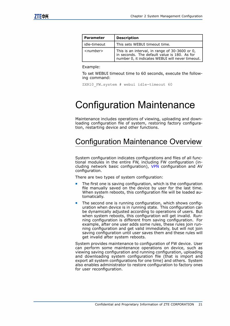
3. Seting WEBUI timeout time.
Command Function
ZXR10_FW.system #webui idle-timeout<number>
This sets WEBUItimeout time.
Parameter Description:
20 Confidential and Proprietary Information of ZTE CORPORATION
Chapter 2 System Management Configuration
Parameter Description
idle-timeout This sets WEBUI timeout time.
<number> This is an interval, in range of 30-3600 or 0,in seconds. The default value is 180. As fornumber 0, it indicates WEBUI will never timeout.
Example:
To set WEBUI timeout time to 60 seconds, execute the follow-ing command:
ZXR10_FW.system # webui idle-timeout 60
Configuration MaintenanceMaintenance includes operations of viewing, uploading and down-loading configuration file of system, restoring factory configura-tion, restarting device and other functions.
Configuration Maintenance Overview
System configuration indicates configurations and files of all func-tional modules in the entire FW, including FW configuration (in-cluding network basic configuration), VPN configuration and AVconfiguration.
There are two types of system configuration:
� The first one is saving configuration, which is the configurationfile manually saved on the device by user for the last time.When system reboots, this configuration file will be loaded au-tomatically.
� The second one is running configuration, which shows config-uration when device is in running state. This configuration canbe dynamically adjusted according to operations of users. Butwhen system reboots, this configuration will get invalid. Run-ning configuration is different from saving configuration. Forexample, after one user adds some rules, these rules join run-ning configuration and get valid immediately, but will not joinsaving configuration until user saves them and these rules willget invalid after system reboots.
System provides maintenance to configuration of FW device. Usercan perform some maintenance operations on device, such asviewing saving configuration and running configuration, uploadingand downloading system configuration file (that is import andexport all system configurations for one time) and others. Systemalso enables administrator to restore configuration to factory onesfor user reconfiguration.
Confidential and Proprietary Information of ZTE CORPORATION 21
ZXR10 8900 Series User Manual (FW Volume)
Configuring Maintenance
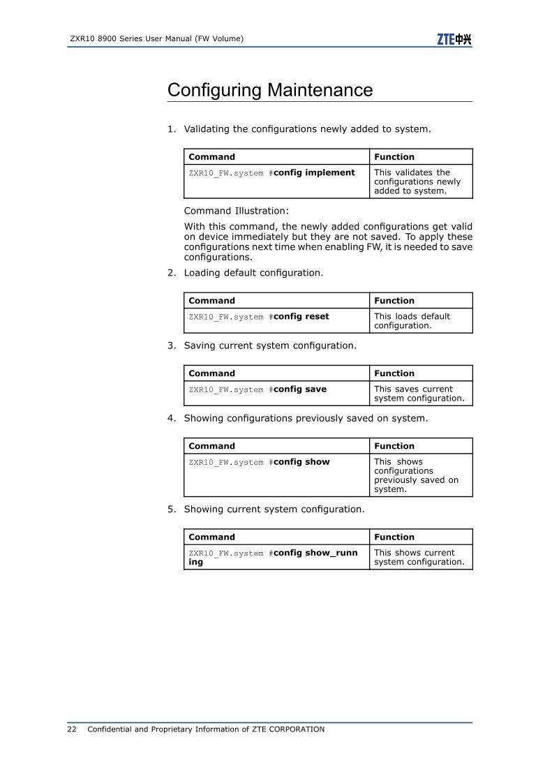
1. Validating the configurations newly added to system.
Command Function
ZXR10_FW.system #config implement This validates theconfigurations newlyadded to system.
Command Illustration:
With this command, the newly added configurations get validon device immediately but they are not saved. To apply theseconfigurations next time when enabling FW, it is needed to saveconfigurations.
2. Loading default configuration.
Command Function
ZXR10_FW.system #config reset This loads defaultconfiguration.
3. Saving current system configuration.
Command Function
ZXR10_FW.system #config save This saves currentsystem configuration.
4. Showing configurations previously saved on system.
Command Function
ZXR10_FW.system #config show This showsconfigurationspreviously saved onsystem.
5. Showing current system configuration.
Command Function
ZXR10_FW.system #config show_running
This shows currentsystem configuration.
22 Confidential and Proprietary Information of ZTE CORPORATION
Chapter 2 System Management Configuration
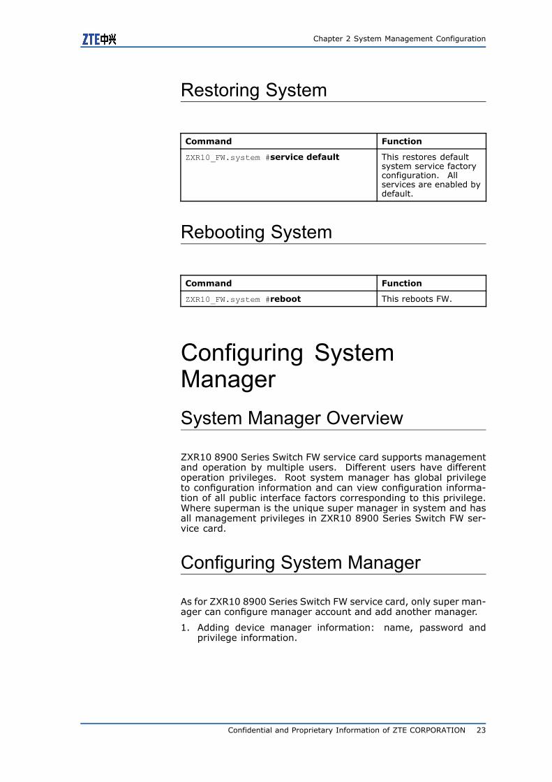
Restoring System
Command Function
ZXR10_FW.system #service default This restores defaultsystem service factoryconfiguration. Allservices are enabled bydefault.
Rebooting System
Command Function
ZXR10_FW.system #reboot This reboots FW.
Configuring SystemManagerSystem Manager Overview
ZXR10 8900 Series Switch FW service card supports managementand operation by multiple users. Different users have differentoperation privileges. Root system manager has global privilegeto configuration information and can view configuration informa-tion of all public interface factors corresponding to this privilege.Where superman is the unique super manager in system and hasall management privileges in ZXR10 8900 Series Switch FW ser-vice card.
Configuring System Manager
As for ZXR10 8900 Series Switch FW service card, only super man-ager can configure manager account and add another manager.
1. Adding device manager information: name, password andprivilege information.
Confidential and Proprietary Information of ZTE CORPORATION 23
ZXR10 8900 Series User Manual (FW Volume)
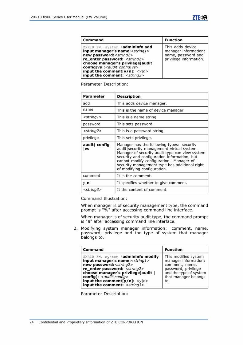
Command Function
ZXR10_FW. system #admininfo addinput manager’s name:<string1>new password:<string2>re_enter password: <string2>choose manager’s privilege[audit|config|vs]:<audit|config|vs>input the comment[y/n]: <y|n>input the comment: <string3>
This adds devicemanager information:name, password andprivilege information.
Parameter Description:
Parameter Description
add This adds device manager.
name This is the name of device manager.
<string1> This is a name string.
password This sets password.
<string2> This is a password string.
privilege This sets privilege.
audit| config|vs
Manager has the following types: securityaudit|security management|virtual system.Manager of security audit type can view systemsecurity and configuration information, butcannot modify configuration. Manager ofsecurity management type has additional rightof modifying configuration.
comment It is the comment.
y|n It specifies whether to give comment.
<string3> It the content of comment.
Command Illustration:
When manager is of security management type, the commandprompt is "%" after accessing command line interface.
When manager is of security audit type, the command promptis "$" after accessing command line interface.
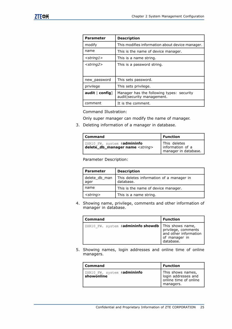
2. Modifying system manager information: comment, name,password, privilege and the type of system that managerbelongs to.
Command Function
ZXR10_FW. system #admininfo modifyinput manager’s name:<string1>new password:<string2>re_enter password: <string2>choose manager’s privilege[audit |config]: <audit|config>input the comment[y/n]: <y|n>input the comment: <string3>
This modifies systemmanager information:comment, name,password, privilegeand the type of systemthat manager belongsto.
Parameter Description:
24 Confidential and Proprietary Information of ZTE CORPORATION
Chapter 2 System Management Configuration
Parameter Description
modify This modifies information about device manager.
name This is the name of device manager.
<string1> This is a name string.
<string2> This is a password string.
new_password This sets password.
privilege This sets privilege.
audit | config] Manager has the following types: securityaudit|security management.
comment It is the comment.
Command Illustration:
Only super manager can modify the name of manager.
3. Deleting information of a manager in database.
Command Function
ZXR10_FW. system #admininfodelete_db_manager name <string>
This deletesinformation of amanager in database.
Parameter Description:
Parameter Description
delete_db_manager
This deletes information of a manager indatabase.
name This is the name of device manager.
<string> This is a name string.
4. Showing name, privilege, comments and other information ofmanager in database.
Command Function
ZXR10_FW. system #admininfo showdb This shows name,privilege, commentsand other informationof manager indatabase.
5. Showing names, login addresses and online time of onlinemanagers.
Command Function
ZXR10_FW. system #admininfoshowonline
This shows names,login addresses andonline time of onlinemanagers.
Confidential and Proprietary Information of ZTE CORPORATION 25
ZXR10 8900 Series User Manual (FW Volume)
System Manager ConfigurationExample
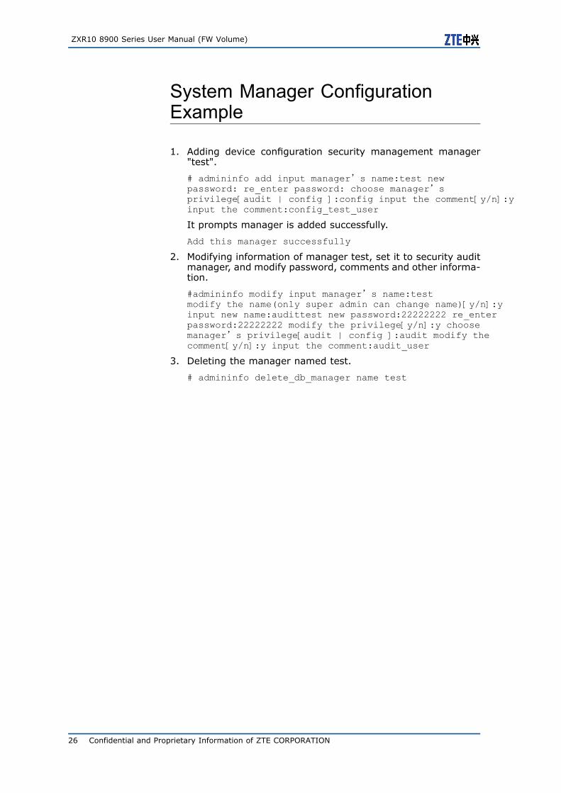
1. Adding device configuration security management manager"test".
# admininfo add input manager’s name:test newpassword: re_enter password: choose manager’sprivilege[audit | config ]:config input the comment[y/n]:yinput the comment:config_test_user
It prompts manager is added successfully.
Add this manager successfully
2. Modifying information of manager test, set it to security auditmanager, and modify password, comments and other informa-tion.
#admininfo modify input manager’s name:testmodify the name(only super admin can change name)[y/n]:yinput new name:audittest new password:22222222 re_enterpassword:22222222 modify the privilege[y/n]:y choosemanager’s privilege[audit | config ]:audit modify thecomment[y/n]:y input the comment:audit_user
3. Deleting the manager named test.
# admininfo delete_db_manager name test
26 Confidential and Proprietary Information of ZTE CORPORATION

C h a p t e r 3
Resource ManagementConfiguration
Table of Contents:Resource Management Overview .........................................27Configuring Address Resource .............................................28Configuring Area Resource..................................................41Configuring Time Resource .................................................44Configuring Service Resource ..............................................50
Resource ManagementOverviewZXR10 8900 Series SwitchMost functions of FW service card arebased on resource, such as access control policy, address trans-lation policy, server load balancing policy, authentication manage-ment and so on. It is necessary to define resources of varioustypes before manager configures ZXR10 8900 Series Switch FWservice card.
The using of concept resource simplifies management to ZXR108900 Series Switch FW service card. When one resource changes,manager only needs to modify properties of resource and doesn’tneed to modify all policies and rules related to this resource.
As for ZXR10 8900 Series Switch FW service card, user can cus-tomize the following resource types:
� Address resource: It includes host resource, address rangeresource, subnet resource and address group.
� Property resource: It includes property resource and propertygroup. Proper resource can get valid only when bound withother resources (such as interface resource, sub-interface re-source, area resource and so on).
� Area resource: It defines area access privilege by being boundwith property resource.
� Time resource: It includes time resources for multi-cycles andsingle-cycle.
� Service resource: It includes system-defined service resource,customized service resource and service group.
Confidential and Proprietary Information of ZTE CORPORATION 27
ZXR10 8900 Series User Manual (FW Volume)
Note:
The following special characters cannot be present in resourcename: space, "’", """, "\", ";", """, "$", "&", "@", "%", "|", "~","<", ">", "#", "+", "!", "=", "^", "?", "‘" (the key under "~").
ZXR10 8900 Series SwitchIt is available to rename resource on FWservice card.
Configuring AddressResourceAddress Resource ConfigurationOverview
Configuration of address resource is the most basic one in resourcemanagement. It needs to select different address resources whendefining access control rules and address translation rules. Usercan set address resources of various types, such as host resource,address range resource and subnet resource, and meanwhile candefine address group to add all these address resources into ad-dress group.
For setting of various address resources and address group, pleaserefer to the following sections.
User can perform management and configuration to above re-sources in DEFINE module of ZXR10 8900 Series Switch FW card.
To access this command module, execute the following command:
#define
To exit this command module, execute the following command:
#end
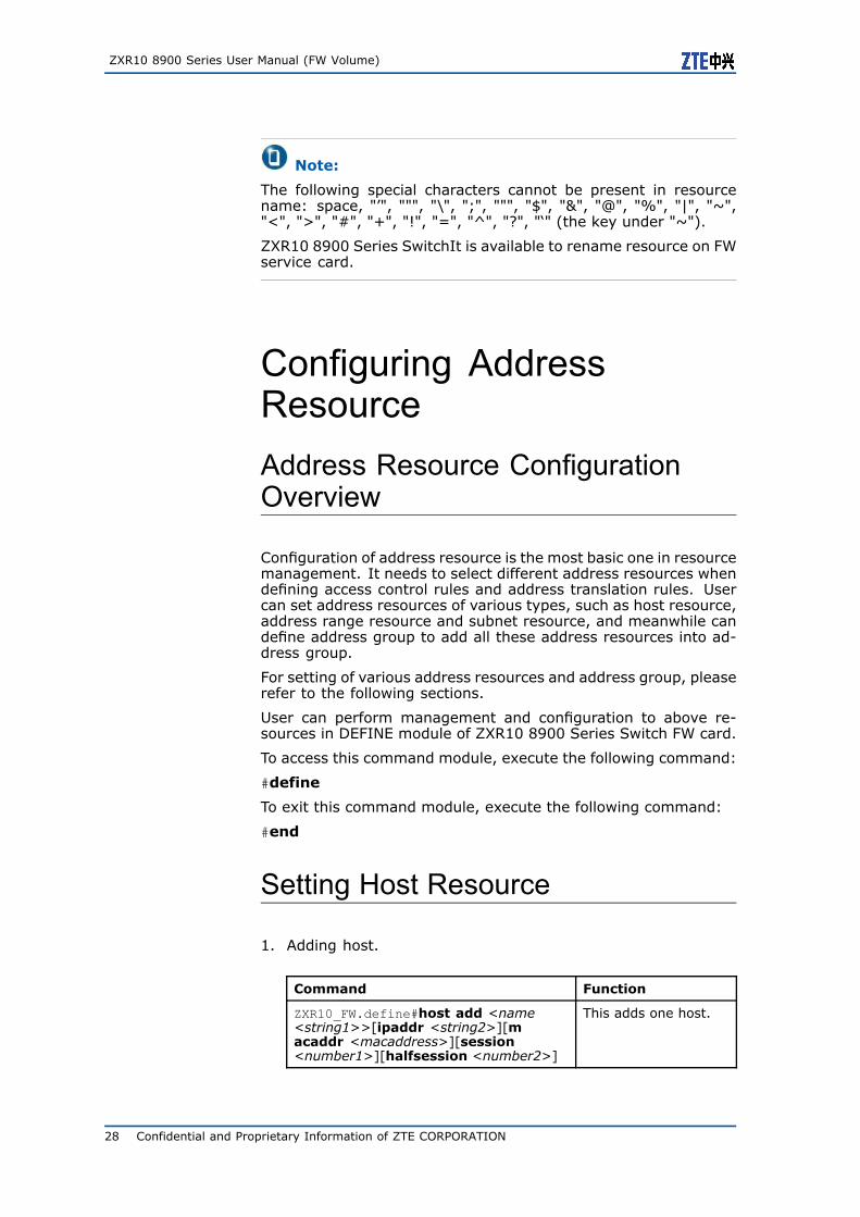
Setting Host Resource
1. Adding host.
Command Function
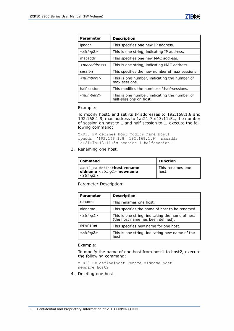
ZXR10_FW.define#host add <name<string1>>[ipaddr <string2>][macaddr <macaddress>][session<number1>][halfsession <number2>]
This adds one host.
28 Confidential and Proprietary Information of ZTE CORPORATION
Chapter 3 Resource Management Configuration
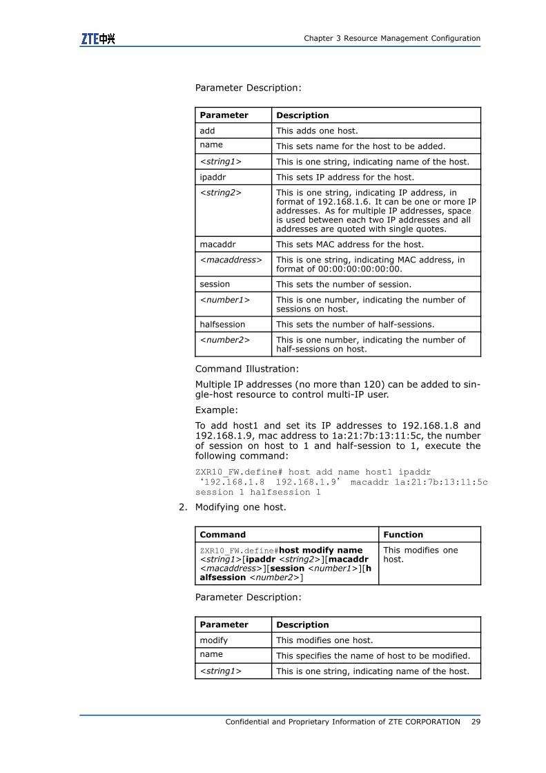
Parameter Description:
Parameter Description
add This adds one host.
name This sets name for the host to be added.
<string1> This is one string, indicating name of the host.
ipaddr This sets IP address for the host.
<string2> This is one string, indicating IP address, informat of 192.168.1.6. It can be one or more IPaddresses. As for multiple IP addresses, spaceis used between each two IP addresses and alladdresses are quoted with single quotes.
macaddr This sets MAC address for the host.
<macaddress> This is one string, indicating MAC address, informat of 00:00:00:00:00:00.
session This sets the number of session.
<number1> This is one number, indicating the number ofsessions on host.
halfsession This sets the number of half-sessions.
<number2> This is one number, indicating the number ofhalf-sessions on host.
Command Illustration:
Multiple IP addresses (no more than 120) can be added to sin-gle-host resource to control multi-IP user.
Example:
To add host1 and set its IP addresses to 192.168.1.8 and192.168.1.9, mac address to 1a:21:7b:13:11:5c, the numberof session on host to 1 and half-session to 1, execute thefollowing command:
ZXR10_FW.define# host add name host1 ipaddr‘192.168.1.8 192.168.1.9’ macaddr 1a:21:7b:13:11:5csession 1 halfsession 1
2. Modifying one host.
Command Function
ZXR10_FW.define#host modify name<string1>[ipaddr <string2>][macaddr<macaddress>][session <number1>][halfsession <number2>]
This modifies onehost.
Parameter Description:
Parameter Description
modify This modifies one host.
name This specifies the name of host to be modified.
<string1> This is one string, indicating name of the host.
Confidential and Proprietary Information of ZTE CORPORATION 29
ZXR10 8900 Series User Manual (FW Volume)
Parameter Description
ipaddr This specifies one new IP address.
<string2> This is one string, indicating IP address.
macaddr This specifies one new MAC address.
<macaddress> This is one string, indicating MAC address.
session This specifies the new number of max sessions.
<number1> This is one number, indicating the number ofmax sessions.
halfsession This modifies the number of half-sessions.
<number2> This is one number, indicating the number ofhalf-sessions on host.
Example:
To modify host1 and set its IP addresses to 192.168.1.8 and192.168.1.9, mac address to 1a:21:7b:13:11:5c, the numberof session on host to 1 and half-session to 1, execute the fol-lowing command:
ZXR10_FW.define# host modify name host1ipaddr ‘192.168.1.8 192.168.1.9’ macaddr1a:21:7b:13:11:5c session 1 halfsession 1
3. Renaming one host.
Command Function
ZXR10_FW.define#host renameoldname <string1> newname<string2>
This renames onehost.
Parameter Description:
Parameter Description
rename This renames one host.
oldname This specifies the name of host to be renamed.
<string1> This is one string, indicating the name of host(the host name has been defined).
newname This specifies new name for one host.
<string2> This is one string, indicating new name of thehost.
Example:
To modify the name of one host from host1 to host2, executethe following command:
ZXR10_FW.define#host rename oldname host1newname host2
4. Deleting one host.
30 Confidential and Proprietary Information of ZTE CORPORATION
Chapter 3 Resource Management Configuration
Command Function
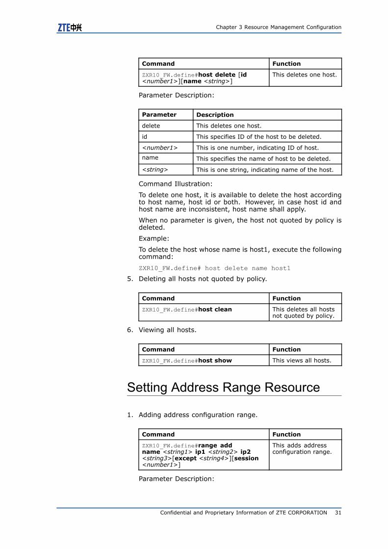
ZXR10_FW.define#host delete [id<number1>][name <string>]
This deletes one host.
Parameter Description:
Parameter Description
delete This deletes one host.
id This specifies ID of the host to be deleted.
<number1> This is one number, indicating ID of host.
name This specifies the name of host to be deleted.
<string> This is one string, indicating name of the host.
Command Illustration:
To delete one host, it is available to delete the host accordingto host name, host id or both. However, in case host id andhost name are inconsistent, host name shall apply.
When no parameter is given, the host not quoted by policy isdeleted.
Example:
To delete the host whose name is host1, execute the followingcommand:
ZXR10_FW.define# host delete name host1
5. Deleting all hosts not quoted by policy.
Command Function
ZXR10_FW.define#host clean This deletes all hostsnot quoted by policy.
6. Viewing all hosts.
Command Function
ZXR10_FW.define#host show This views all hosts.
Setting Address Range Resource
1. Adding address configuration range.
Command Function
ZXR10_FW.define#range addname <string1> ip1 <string2> ip2<string3>[except <string4>][session<number1>]
This adds addressconfiguration range.
Parameter Description:
Confidential and Proprietary Information of ZTE CORPORATION 31
ZXR10 8900 Series User Manual (FW Volume)
Parameter Description
add This adds address range.
name This sets name for address range.
<string1> This is one string, indicating the name ofaddress range.
ip1 This sets start IP address for address range.
<string2> This is one string, indicating IP address, informat of 0.0.0.0.
ip2 This sets end IP address for address range.
<string3> This is one string, indicating IP address, informat of 0.0.0.0.
except This sets except IP address in address range.
<string4> This is one string, indicating IP address, informat of 0.0.0.0.
session This sets the number of session.
<number1> This is one number, indicating the number ofsessions.
Command Illustration:
The value of ip1 mustn’t be larger than that of ip2, or it willreport error. The value of parameter Except shall be withinthe range between Ipaddress1 and Ipaddress2.
The default range configuration for ZXR10 8900 Series SwitchFW service card is any0.0.0.0-255.255.255.255. At the samemoment, the number of connections of individual addresseswithin the address range cannot exceed the number of maxsessions.
Example:
To add address range1 and set the range to 192.16.1.10-192.16.2.81, execute the following command:
ZXR10_FW.define# range add name range1 ip1192.16.1.10 ip2 192.16.2.81
2. Modifying address configuration range.
Command Function
ZXR10_FW.define#range modifyname <string1> ip1 <string2> ip2<string3>[except <string4>][session<number1>]
User can add, modifyand delete addressrange in managementof address range ofFW.
Parameter Description:
Parameter Description
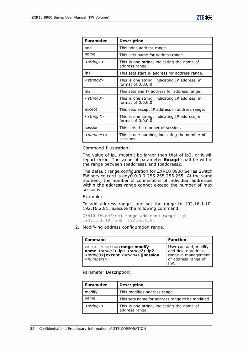
modify This modifies address range.
name This sets name for address range to be modified.
<string1> This is one string, indicating the name ofaddress range.
32 Confidential and Proprietary Information of ZTE CORPORATION

Chapter 3 Resource Management Configuration
Parameter Description
ip1 This sets start IP address for address range.
<string2> This is one string, indicating IP address, informat of 0.0.0.0.
ip2 This sets end IP address for address range.
<string3> This is one string, indicating IP address, informat of 0.0.0.0.
except This sets except IP address in address range.
<string4> This is one string, indicating IP address, informat of 0.0.0.0.
session This sets the number of session.
<number1> This is one number, indicating the number ofsessions.
Command Illustration:
At the same moment, the total number of connections of allhosts within the address range cannot exceed the number ofmax sessions.
Example:
To modify address range to 192.16.1.11—192.16.2.82 afteradding range1 with address 192.16.2.1 excepted, execute thefollowing command:
ZXR10_FW.define# range modify name range1ip1 192.16.1.11 ip2 192.16.2.82 except 192.16.2.1
3. Renaming address configuraiton range.
Command Function
ZXR10_FW.define#range renameoldname <string1> newname<string2>
This renames addressrange.
Parameter Description:
Parameter Description
rename This renames address range.
oldname This specifies the name of address range to berenamed.
<string1> This is one string, indicating the name ofaddress range (the name of address range hasbeen defined).
newname This specifies new name for address range.
<string2> This is one string, indicating the new name ofaddress range.
Example:
To rename address range1 to range2, execute the followingcommand:
Confidential and Proprietary Information of ZTE CORPORATION 33
ZXR10 8900 Series User Manual (FW Volume)
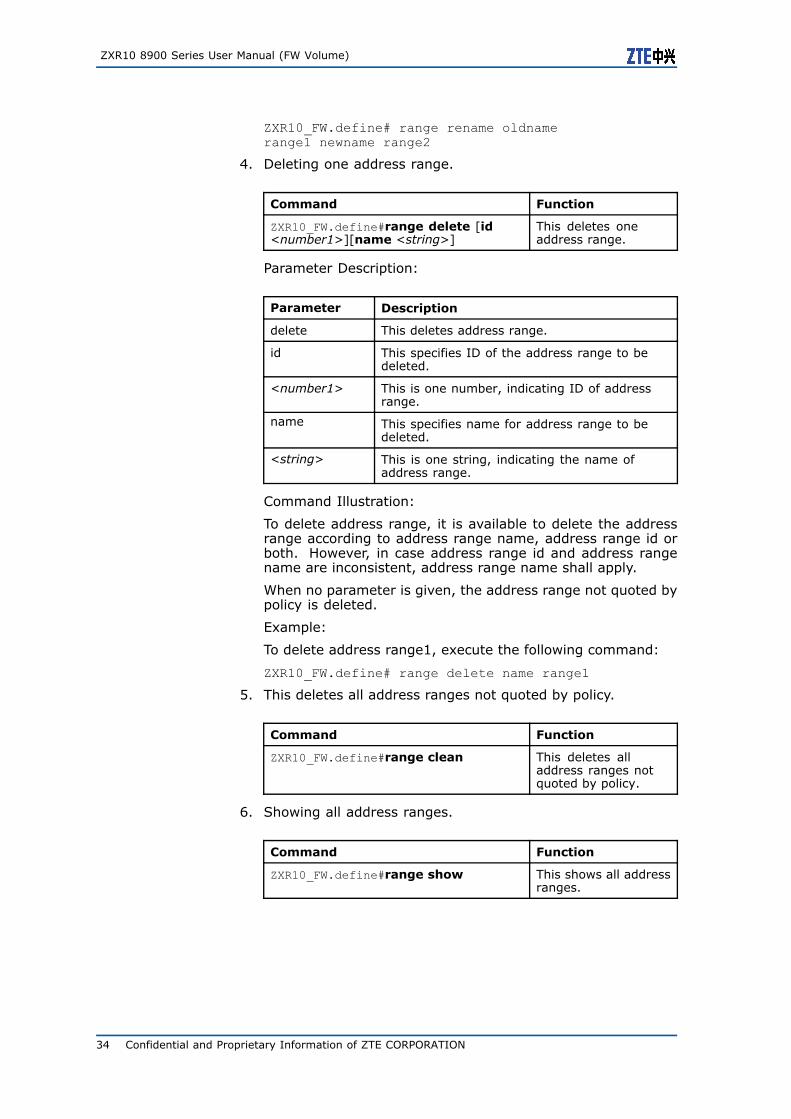
ZXR10_FW.define# range rename oldnamerange1 newname range2
4. Deleting one address range.
Command Function
ZXR10_FW.define#range delete [id<number1>][name <string>]
This deletes oneaddress range.
Parameter Description:
Parameter Description
delete This deletes address range.
id This specifies ID of the address range to bedeleted.
<number1> This is one number, indicating ID of addressrange.
name This specifies name for address range to bedeleted.
<string> This is one string, indicating the name ofaddress range.
Command Illustration:
To delete address range, it is available to delete the addressrange according to address range name, address range id orboth. However, in case address range id and address rangename are inconsistent, address range name shall apply.
When no parameter is given, the address range not quoted bypolicy is deleted.
Example:
To delete address range1, execute the following command:
ZXR10_FW.define# range delete name range1
5. This deletes all address ranges not quoted by policy.
Command Function
ZXR10_FW.define#range clean This deletes alladdress ranges notquoted by policy.
6. Showing all address ranges.
Command Function
ZXR10_FW.define#range show This shows all addressranges.
34 Confidential and Proprietary Information of ZTE CORPORATION
Chapter 3 Resource Management Configuration
Setting Subnet Resource
1. Adding one subnet.
Command Function
ZXR10_FW.define#subnet add name<string1> ipaddr <ipaddress> mask<netmask>[except <string2>][session<number1>]
This adds one subnet.
Parameter Description:
Parameter Description
add This adds one subnet.
name This sets name for subnet.
<string> This is one string, indicating name of the subnet.
ipaddr This sets address for subnet.
<ipaddress> This is one string, indicating ip address ofsubnet, such as 192.168.8.0.
mask This sets subnet mask.
<netmask> This is one string, indicating subnet mask, suchas 255.255.255.0.
except This sets except address in subnet.
<string2> This is one string, indicating excepted IPaddress, in format of 0.0.0.0.
session This sets the number of sessions.
<number1> This is one number, indicating the number ofsessions.
Command Illustration:
At the same moment, the number of connections of individualaddresses within the subnet cannot exceed the number of maxsessions.
Example:
To add subnet1 with subnet address to be 192.168.10.0 andmask to be 255.255.255.0, execute the following command:
ZXR10_FW.define# subnet add name subnet1ipaddr 192.168.10.0 mask 255.255.255.0
2. Modifying one subnet.
Command Function
ZXR10_FW.define#subnet modify name<string1>[ipaddr <ipaddress>][mask<netmask>][except <string2>][session<number1>]
This modifies onesubnet.
Parameter Description:
Confidential and Proprietary Information of ZTE CORPORATION 35
ZXR10 8900 Series User Manual (FW Volume)
Parameter Description
modify This modifies one subnet.
name This specifies the name of subnet to be modified.
<string> This is one string, indicating name of the subnet.
ipaddr This sets new address for subnet.
<ipaddress> This is one string, indicating ip address ofsubnet, such as 192.168.8.0.
mask This sets new subnet mask.
<netmask> This is one string, indicating subnet mask, suchas 255.255.255.0.
except This sets new except address in subnet.
<string2> This is one string, indicating excepted IPaddress, in format of 0.0.0.0.
session This sets new number of session.
<number1> This is one number, indicating the number ofsessions.
Command Illustration:
At the same moment, the total number of connections of allhosts within the subnet cannot exceed the number of max ses-sions.
Example:
To modify IP address of subnet1 to 192.168.20.0, execute thefollowing command:
ZXR10_FW.define# subnet modify namesubnet1 ipaddr 192.168.20.0
3. Renaming one subnet.
Command Function
ZXR10_FW.define#subnet renameoldname <string1> newname<string2>
This renames onesubnet.
Parameter Description:
Parameter Description
rename This renames one subnet.
oldname This specifies the name of subnet to berenamed.
<string1> This is one string, indicating the name of subnet(the subnet name has been defined).
newname This specifies new name for the subnet.
<string2> This is one string, indicating new name of thesubnet.
Command Illustration:
36 Confidential and Proprietary Information of ZTE CORPORATION
Chapter 3 Resource Management Configuration
At the same moment, the total number of connections of allhosts within the subnet cannot exceed the number of max ses-sions.
Example:
To rename subnet1 to subnet2, execute the following com-mand:
ZXR10_FW.define# subnet rename oldnamesubnet1 newname subnet2
4. Deleting one subnet.
Command Function
ZXR10_FW.define#subnet delete [id<number1>][name <string>]
This deletes onesubnet.
Parameter Description:
Parameter Description
delete This deletes one subnet.
id This specifies ID of the subnet to be deleted.
<number> This is one number, indicating ID of subnet.
name This specifies the name of subnet to be deleted.
<string> This is one string, indicating name of the subnet.
Command Illustration:
To delete one subnet, it is available to delete the subnet ac-cording to subnet name, subnet id or both. However, in casesubnet id and subnet name are inconsistent, subnet name shallapply.
When no parameter is given, the subnet not quoted by policyis deleted.
Example:
To delete subnet1, execute the following command:
ZXR10_FW.define# subnet delete name subnet1
5. This deletes all subnets not quoted by policy.
Command Function
ZXR10_FW.define#subnet clean This deletes allsubnets not quoted bypolicy.
6. Showing all subnets.
Command Function
ZXR10_FW.define#subnet show This shows allsubnets.
Confidential and Proprietary Information of ZTE CORPORATION 37
ZXR10 8900 Series User Manual (FW Volume)
Setting Address Group
Different address resources can be combined to one address groupto define policy destination or policy source. With address group,resource management is more flexible.
1. Adding one address group.
Command Function
ZXR10_FW.define#group_address addname <string1>[member <string2>]
This adds one addressgroup.
Parameter Description:
Parameter Description
add This adds one address group.
name This sets name for address group.
<string1> This is one string, indicating the name ofaddress group.
member This sets member in address group.
<string2> This is one string, indicating address object,which can be defined host object, subnet objector address range object.
Command Illustration:
Before defining one address group, define address object. Fordetails, please refer to related sections.
Example:
To add groupaddr1 and set defined host1 as the group member,execute the following command:
ZXR10_FW.define# group_address add namegroupaddr1 member host1
2. This adds member to defined address group.
Command Function
ZXR10_FW.define#group_addressaddmember groupname <string1>member <string2>
This adds memberto defined addressgroup.
Parameter Description:
Parameter Description
addmember This adds member to address group.
name This specifies name for address group to whichmember will be added.
<string1> This is one string, indicating the name ofaddress group.
38 Confidential and Proprietary Information of ZTE CORPORATION
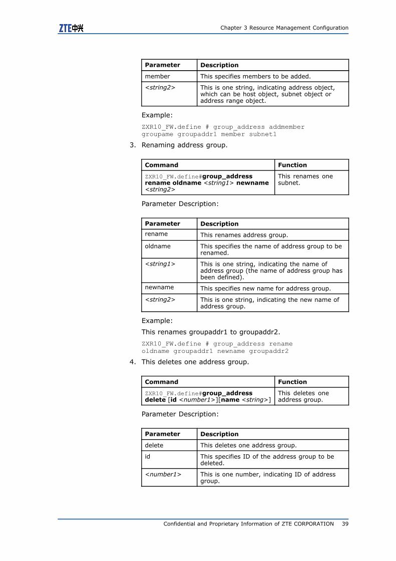
Chapter 3 Resource Management Configuration
Parameter Description
member This specifies members to be added.
<string2> This is one string, indicating address object,which can be host object, subnet object oraddress range object.
Example:
ZXR10_FW.define # group_address addmembergroupame groupaddr1 member subnet1
3. Renaming address group.
Command Function
ZXR10_FW.define#group_addressrename oldname <string1> newname<string2>
This renames onesubnet.
Parameter Description:
Parameter Description
rename This renames address group.
oldname This specifies the name of address group to berenamed.
<string1> This is one string, indicating the name ofaddress group (the name of address group hasbeen defined).
newname This specifies new name for address group.
<string2> This is one string, indicating the new name ofaddress group.
Example:
This renames groupaddr1 to groupaddr2.
ZXR10_FW.define # group_address renameoldname groupaddr1 newname groupaddr2
4. This deletes one address group.
Command Function
ZXR10_FW.define#group_addressdelete [id <number1>][name <string>]
This deletes oneaddress group.
Parameter Description:
Parameter Description
delete This deletes one address group.
id This specifies ID of the address group to bedeleted.
<number1> This is one number, indicating ID of addressgroup.
Confidential and Proprietary Information of ZTE CORPORATION 39
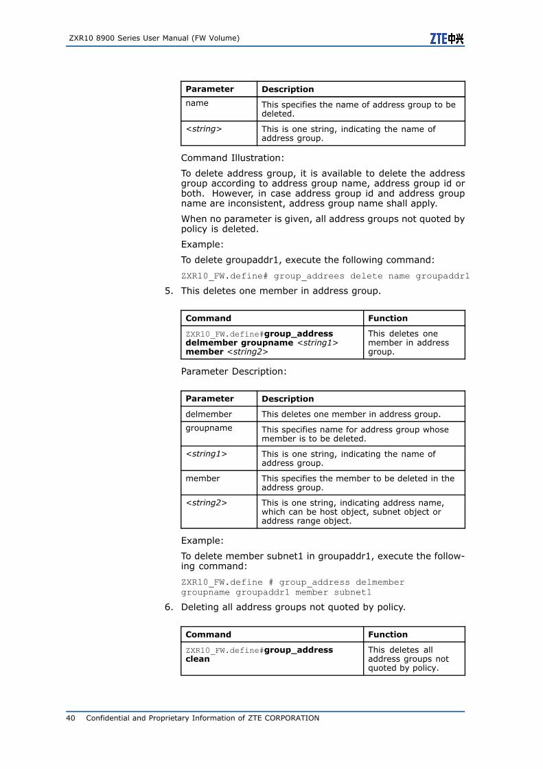
ZXR10 8900 Series User Manual (FW Volume)
Parameter Description
name This specifies the name of address group to bedeleted.
<string> This is one string, indicating the name ofaddress group.
Command Illustration:
To delete address group, it is available to delete the addressgroup according to address group name, address group id orboth. However, in case address group id and address groupname are inconsistent, address group name shall apply.
When no parameter is given, all address groups not quoted bypolicy is deleted.
Example:
To delete groupaddr1, execute the following command:
ZXR10_FW.define# group_addrees delete name groupaddr1
5. This deletes one member in address group.
Command Function
ZXR10_FW.define#group_addressdelmember groupname <string1>member <string2>
This deletes onemember in addressgroup.
Parameter Description:
Parameter Description
delmember This deletes one member in address group.
groupname This specifies name for address group whosemember is to be deleted.
<string1> This is one string, indicating the name ofaddress group.
member This specifies the member to be deleted in theaddress group.
<string2> This is one string, indicating address name,which can be host object, subnet object oraddress range object.
Example:
To delete member subnet1 in groupaddr1, execute the follow-ing command:
ZXR10_FW.define # group_address delmembergroupname groupaddr1 member subnet1
6. Deleting all address groups not quoted by policy.
Command Function
ZXR10_FW.define#group_addressclean
This deletes alladdress groups notquoted by policy.
40 Confidential and Proprietary Information of ZTE CORPORATION
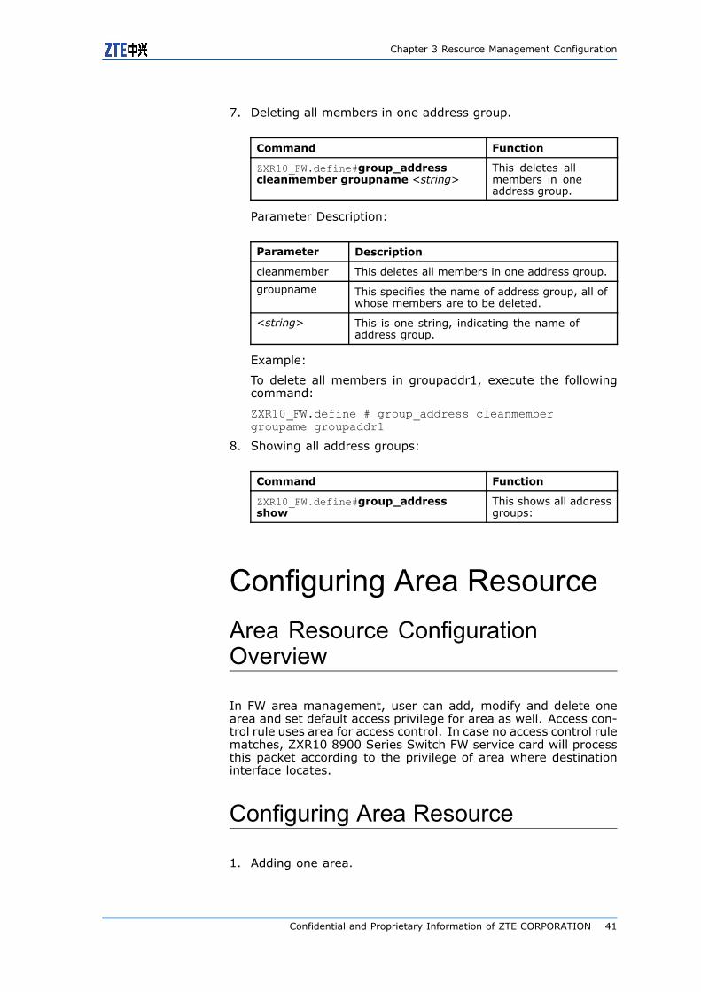
Chapter 3 Resource Management Configuration
7. Deleting all members in one address group.
Command Function
ZXR10_FW.define#group_addresscleanmember groupname <string>
This deletes allmembers in oneaddress group.
Parameter Description:
Parameter Description
cleanmember This deletes all members in one address group.
groupname This specifies the name of address group, all ofwhose members are to be deleted.
<string> This is one string, indicating the name ofaddress group.
Example:
To delete all members in groupaddr1, execute the followingcommand:
ZXR10_FW.define # group_address cleanmembergroupame groupaddr1
8. Showing all address groups:
Command Function
ZXR10_FW.define#group_addressshow
This shows all addressgroups:
Configuring Area ResourceArea Resource ConfigurationOverview
In FW area management, user can add, modify and delete onearea and set default access privilege for area as well. Access con-trol rule uses area for access control. In case no access control rulematches, ZXR10 8900 Series Switch FW service card will processthis packet according to the privilege of area where destinationinterface locates.
Configuring Area Resource
1. Adding one area.
Confidential and Proprietary Information of ZTE CORPORATION 41
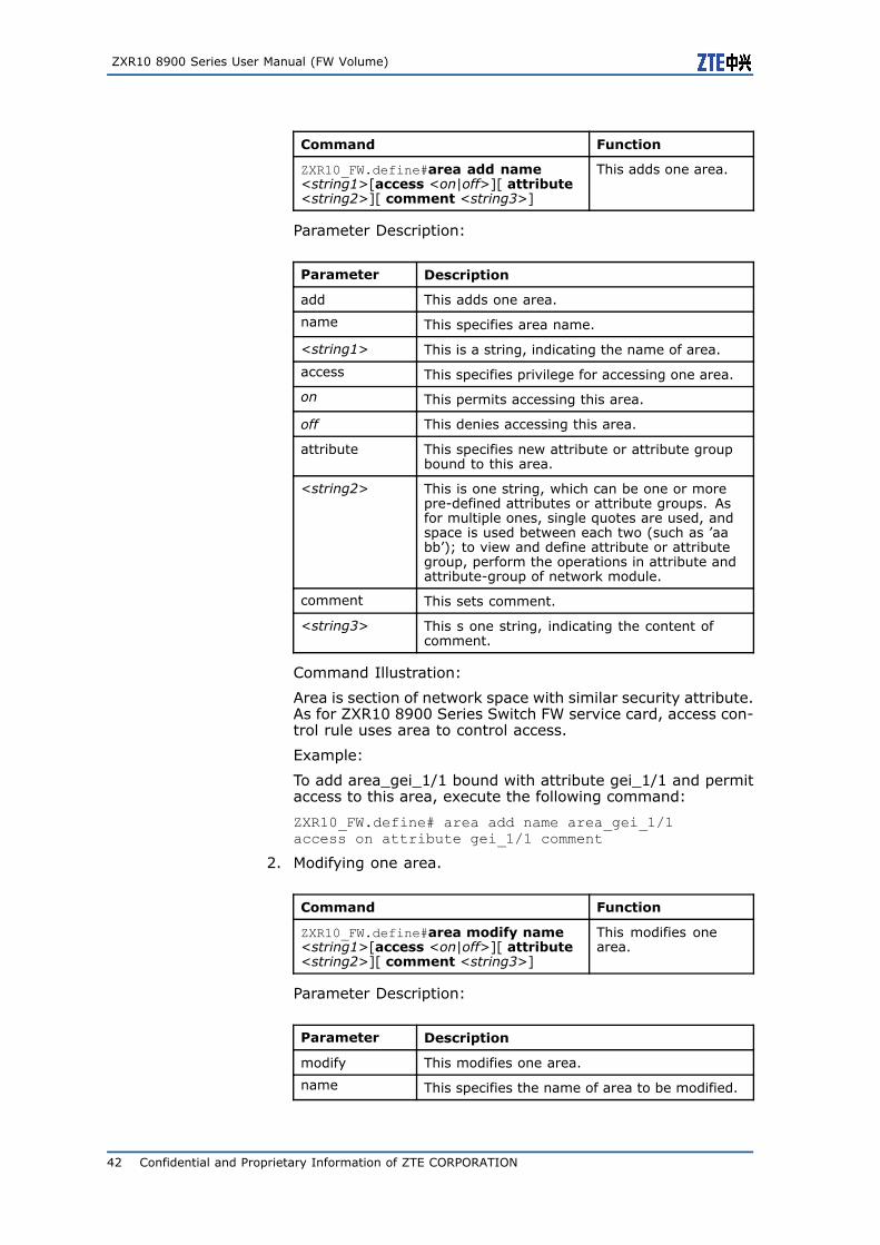
ZXR10 8900 Series User Manual (FW Volume)
Command Function
ZXR10_FW.define#area add name<string1>[access <on|off>][ attribute<string2>][ comment <string3>]
This adds one area.
Parameter Description:
Parameter Description
add This adds one area.
name This specifies area name.
<string1> This is a string, indicating the name of area.
access This specifies privilege for accessing one area.
on This permits accessing this area.
off This denies accessing this area.
attribute This specifies new attribute or attribute groupbound to this area.
<string2> This is one string, which can be one or morepre-defined attributes or attribute groups. Asfor multiple ones, single quotes are used, andspace is used between each two (such as ’aabb’); to view and define attribute or attributegroup, perform the operations in attribute andattribute-group of network module.
comment This sets comment.
<string3> This s one string, indicating the content ofcomment.
Command Illustration:
Area is section of network space with similar security attribute.As for ZXR10 8900 Series Switch FW service card, access con-trol rule uses area to control access.
Example:
To add area_gei_1/1 bound with attribute gei_1/1 and permitaccess to this area, execute the following command:
ZXR10_FW.define# area add name area_gei_1/1access on attribute gei_1/1 comment
2. Modifying one area.
Command Function
ZXR10_FW.define#area modify name<string1>[access <on|off>][ attribute<string2>][ comment <string3>]
This modifies onearea.
Parameter Description:
Parameter Description
modify This modifies one area.
name This specifies the name of area to be modified.
42 Confidential and Proprietary Information of ZTE CORPORATION
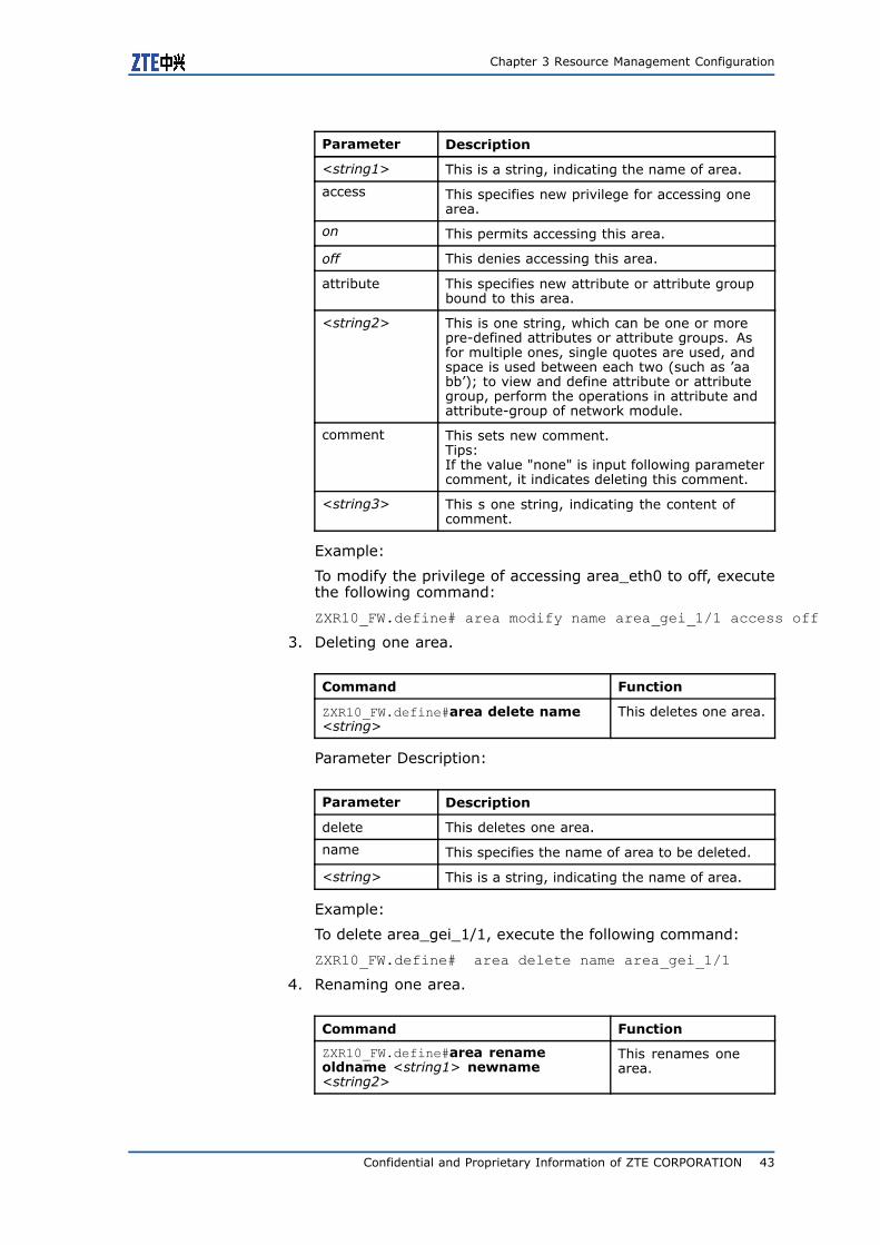
Chapter 3 Resource Management Configuration
Parameter Description
<string1> This is a string, indicating the name of area.
access This specifies new privilege for accessing onearea.
on This permits accessing this area.
off This denies accessing this area.
attribute This specifies new attribute or attribute groupbound to this area.
<string2> This is one string, which can be one or morepre-defined attributes or attribute groups. Asfor multiple ones, single quotes are used, andspace is used between each two (such as ’aabb’); to view and define attribute or attributegroup, perform the operations in attribute andattribute-group of network module.
comment This sets new comment.Tips:If the value "none" is input following parametercomment, it indicates deleting this comment.
<string3> This s one string, indicating the content ofcomment.
Example:
To modify the privilege of accessing area_eth0 to off, executethe following command:
ZXR10_FW.define# area modify name area_gei_1/1 access off
3. Deleting one area.
Command Function
ZXR10_FW.define#area delete name<string>
This deletes one area.
Parameter Description:
Parameter Description
delete This deletes one area.
name This specifies the name of area to be deleted.
<string> This is a string, indicating the name of area.
Example:
To delete area_gei_1/1, execute the following command:
ZXR10_FW.define# area delete name area_gei_1/1
4. Renaming one area.
Command Function
ZXR10_FW.define#area renameoldname <string1> newname<string2>
This renames onearea.
Confidential and Proprietary Information of ZTE CORPORATION 43
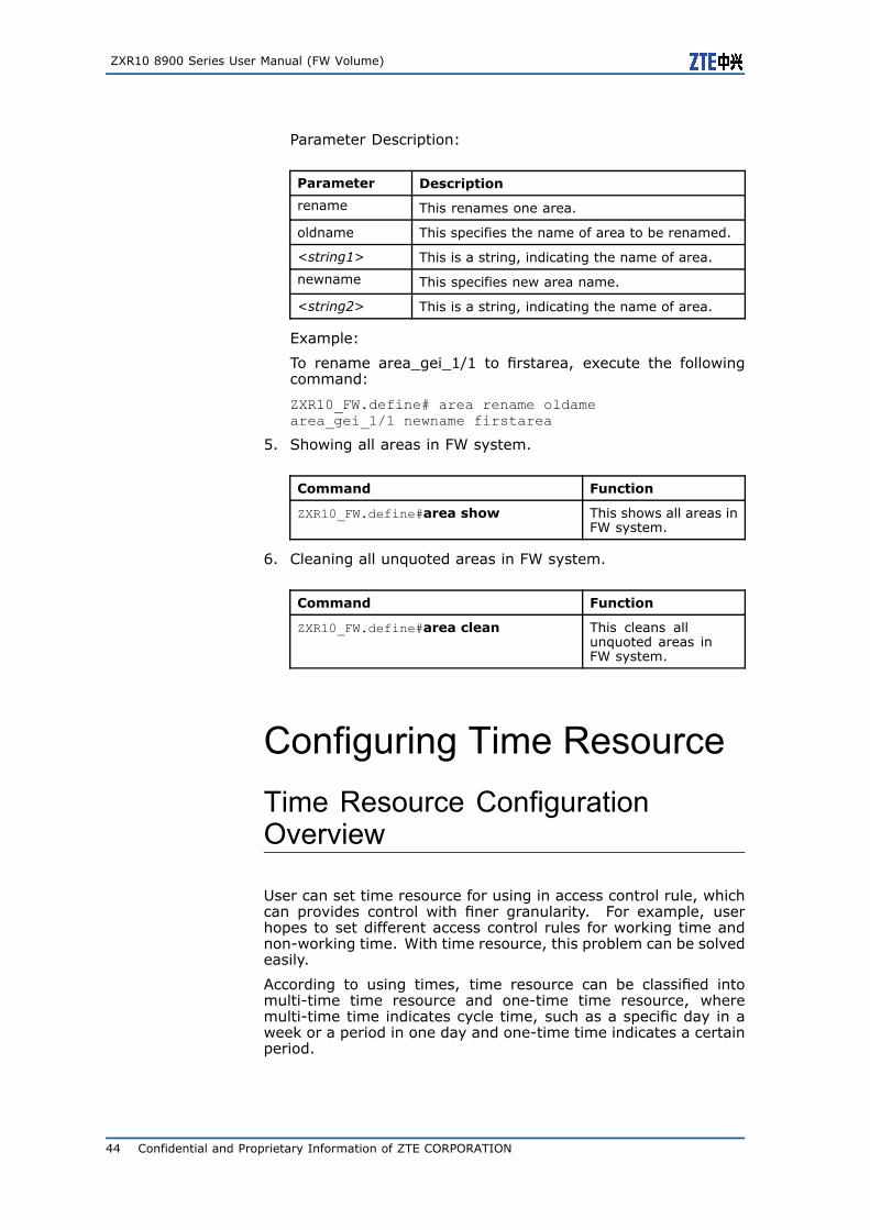
ZXR10 8900 Series User Manual (FW Volume)
Parameter Description:
Parameter Description
rename This renames one area.
oldname This specifies the name of area to be renamed.
<string1> This is a string, indicating the name of area.
newname This specifies new area name.
<string2> This is a string, indicating the name of area.
Example:
To rename area_gei_1/1 to firstarea, execute the followingcommand:
ZXR10_FW.define# area rename oldamearea_gei_1/1 newname firstarea
5. Showing all areas in FW system.
Command Function
ZXR10_FW.define#area show This shows all areas inFW system.
6. Cleaning all unquoted areas in FW system.
Command Function
ZXR10_FW.define#area clean This cleans allunquoted areas inFW system.
Configuring Time ResourceTime Resource ConfigurationOverview
User can set time resource for using in access control rule, whichcan provides control with finer granularity. For example, userhopes to set different access control rules for working time andnon-working time. With time resource, this problem can be solvedeasily.
According to using times, time resource can be classified intomulti-time time resource and one-time time resource, wheremulti-time time indicates cycle time, such as a specific day in aweek or a period in one day and one-time time indicates a certainperiod.
44 Confidential and Proprietary Information of ZTE CORPORATION
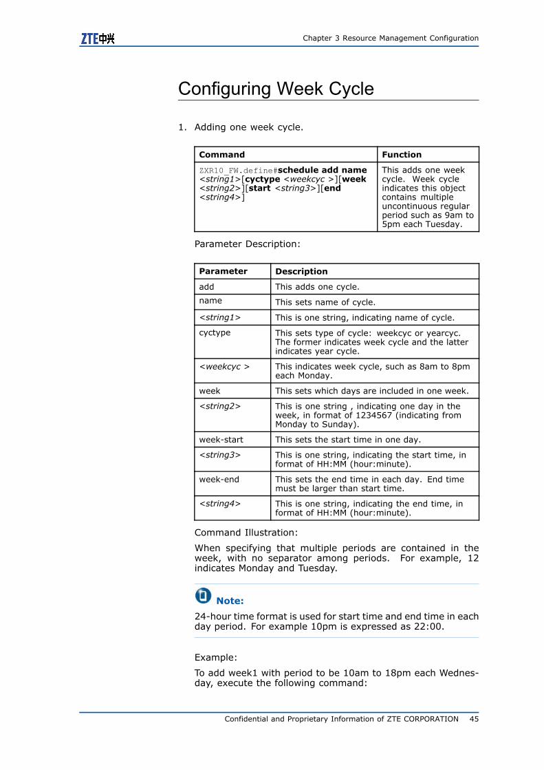
Chapter 3 Resource Management Configuration
Configuring Week Cycle
1. Adding one week cycle.
Command Function
ZXR10_FW.define#schedule add name<string1>[cyctype <weekcyc >][week<string2>][start <string3>][end<string4>]
This adds one weekcycle. Week cycleindicates this objectcontains multipleuncontinuous regularperiod such as 9am to5pm each Tuesday.
Parameter Description:
Parameter Description
add This adds one cycle.
name This sets name of cycle.
<string1> This is one string, indicating name of cycle.
cyctype This sets type of cycle: weekcyc or yearcyc.The former indicates week cycle and the latterindicates year cycle.
<weekcyc > This indicates week cycle, such as 8am to 8pmeach Monday.
week This sets which days are included in one week.
<string2> This is one string , indicating one day in theweek, in format of 1234567 (indicating fromMonday to Sunday).
week-start This sets the start time in one day.
<string3> This is one string, indicating the start time, informat of HH:MM (hour:minute).
week-end This sets the end time in each day. End timemust be larger than start time.
<string4> This is one string, indicating the end time, informat of HH:MM (hour:minute).
Command Illustration:
When specifying that multiple periods are contained in theweek, with no separator among periods. For example, 12indicates Monday and Tuesday.
Note:
24-hour time format is used for start time and end time in eachday period. For example 10pm is expressed as 22:00.
Example:
To add week1 with period to be 10am to 18pm each Wednes-day, execute the following command:
Confidential and Proprietary Information of ZTE CORPORATION 45
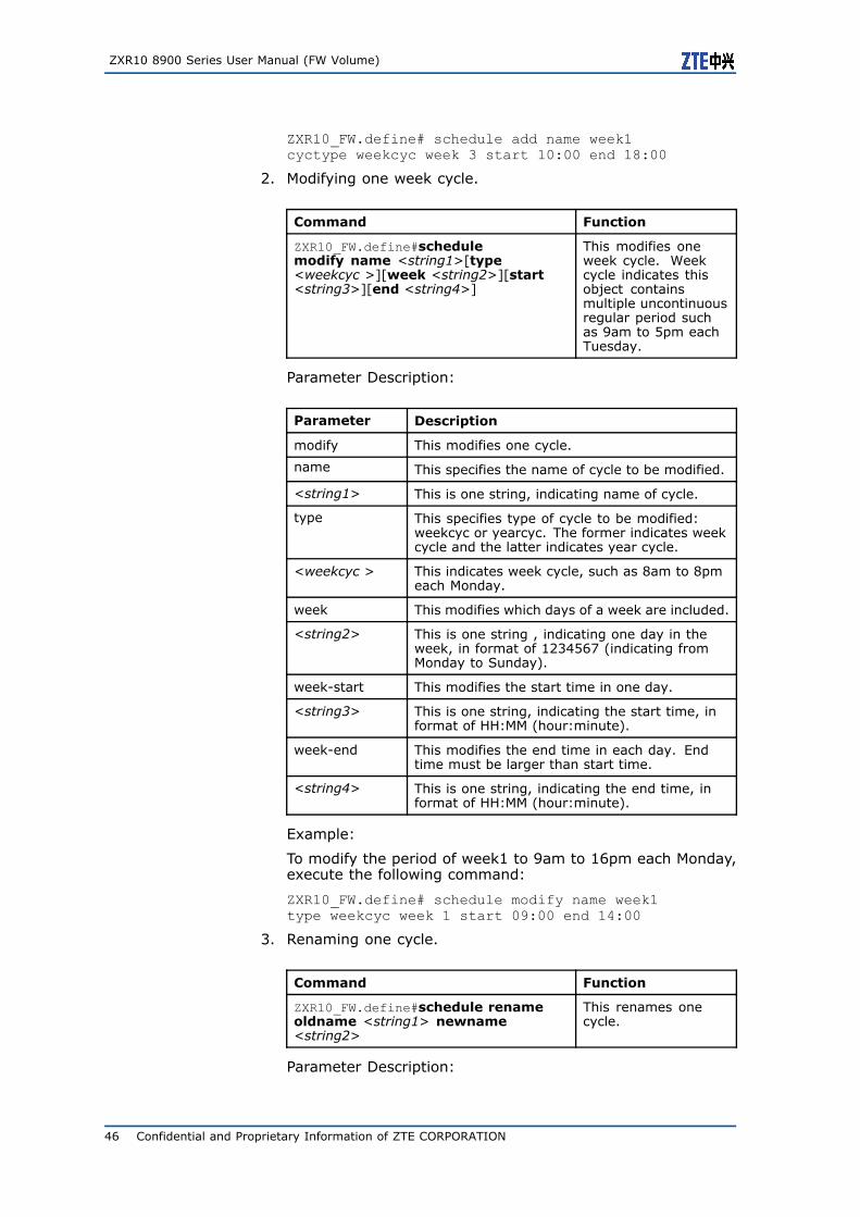
ZXR10 8900 Series User Manual (FW Volume)
ZXR10_FW.define# schedule add name week1cyctype weekcyc week 3 start 10:00 end 18:00
2. Modifying one week cycle.
Command Function
ZXR10_FW.define#schedulemodify name <string1>[type<weekcyc >][week <string2>][start<string3>][end <string4>]
This modifies oneweek cycle. Weekcycle indicates thisobject containsmultiple uncontinuousregular period suchas 9am to 5pm eachTuesday.
Parameter Description:
Parameter Description
modify This modifies one cycle.
name This specifies the name of cycle to be modified.
<string1> This is one string, indicating name of cycle.
type This specifies type of cycle to be modified:weekcyc or yearcyc. The former indicates weekcycle and the latter indicates year cycle.
<weekcyc > This indicates week cycle, such as 8am to 8pmeach Monday.
week This modifies which days of a week are included.
<string2> This is one string , indicating one day in theweek, in format of 1234567 (indicating fromMonday to Sunday).
week-start This modifies the start time in one day.
<string3> This is one string, indicating the start time, informat of HH:MM (hour:minute).
week-end This modifies the end time in each day. Endtime must be larger than start time.
<string4> This is one string, indicating the end time, informat of HH:MM (hour:minute).
Example:
To modify the period of week1 to 9am to 16pm each Monday,execute the following command:
ZXR10_FW.define# schedule modify name week1type weekcyc week 1 start 09:00 end 14:00
3. Renaming one cycle.
Command Function
ZXR10_FW.define#schedule renameoldname <string1> newname<string2>
This renames onecycle.
Parameter Description:
46 Confidential and Proprietary Information of ZTE CORPORATION

Chapter 3 Resource Management Configuration
Parameter Description
rename This renames one cycle.
oldname This specifies the name of cycle to be renamed.
<string1> This is one string, indicating the name of cycle(the cycle name has been defined).
newname This specifies new name for the cycle.
<string2> This is one string, indicating new name of cycle.
Example:
To rename week1 to week2, execute the following command:
ZXR10_FW.define# schedule rename oldname week1newname week2
4. Deleting one cycle.
Command Function
ZXR10_FW.define#schedule delete [id<number1>][name <string>]
This deletes one cycle.
Parameter Description:
Parameter Description
delete This deletes one cycle.
id This specifies ID of the cycle to be deleted.
<number1> This is one number, indicating ID of cycle.
name This specifies the name of cycle to be deleted.
<string> This is one string, indicating name of cycle.
Example:
To delete week1, execute the following command:
ZXR10_FW.define# schedule delete name week1
Configuring Year Cycle
1. Adding one year cycle
Command Function
ZXR10_FW.define#schedule add name<string1>[cyctype <yearcyc>][sdate<string2>][stime <string3>][edate <string4>][etime < string5>]
This adds one yearcycle, which indicatesit only contains oneperiod, such as fromam 0 on January 1,2007 to pm 23 onDecember 12, 2007.
Parameter Description:
Confidential and Proprietary Information of ZTE CORPORATION 47
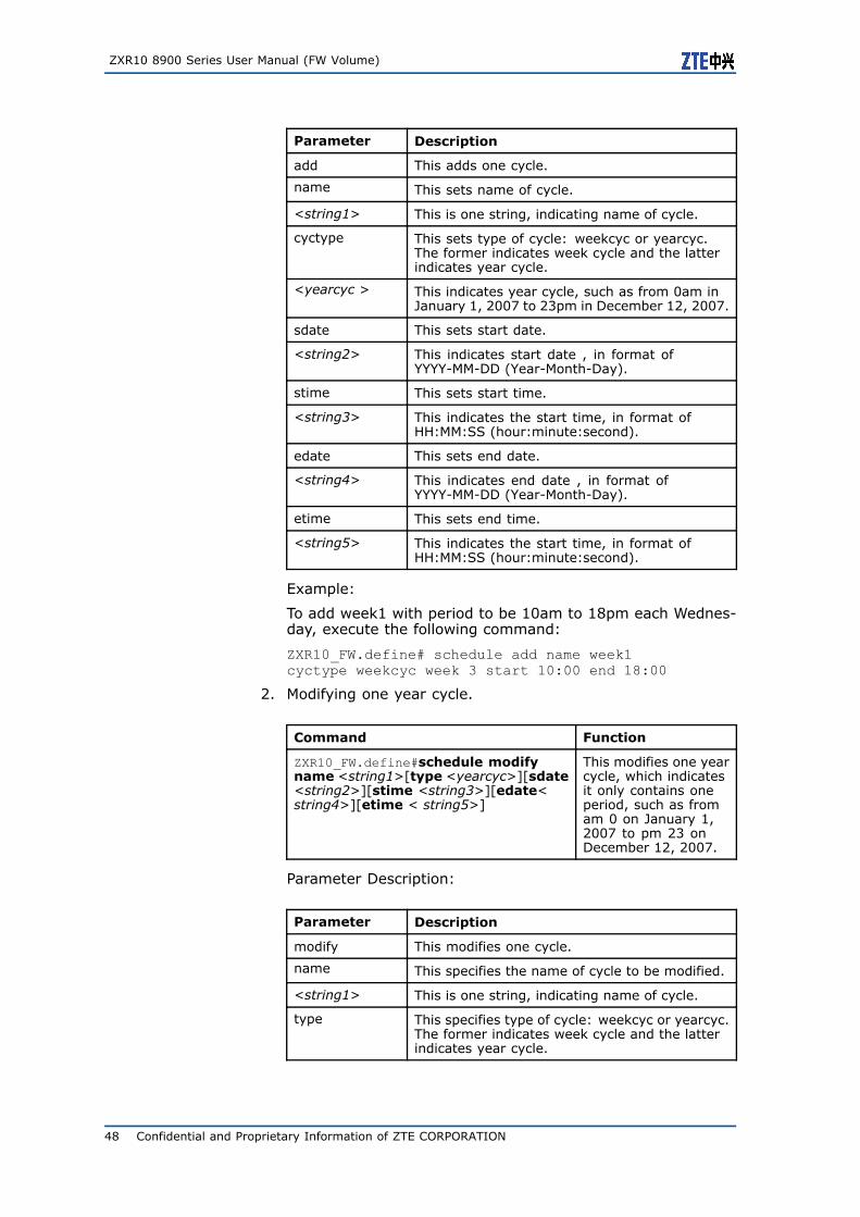
ZXR10 8900 Series User Manual (FW Volume)
Parameter Description
add This adds one cycle.
name This sets name of cycle.
<string1> This is one string, indicating name of cycle.
cyctype This sets type of cycle: weekcyc or yearcyc.The former indicates week cycle and the latterindicates year cycle.
<yearcyc > This indicates year cycle, such as from 0am inJanuary 1, 2007 to 23pm in December 12, 2007.
sdate This sets start date.
<string2> This indicates start date , in format ofYYYY-MM-DD (Year-Month-Day).
stime This sets start time.
<string3> This indicates the start time, in format ofHH:MM:SS (hour:minute:second).
edate This sets end date.
<string4> This indicates end date , in format ofYYYY-MM-DD (Year-Month-Day).
etime This sets end time.
<string5> This indicates the start time, in format ofHH:MM:SS (hour:minute:second).
Example:
To add week1 with period to be 10am to 18pm each Wednes-day, execute the following command:
ZXR10_FW.define# schedule add name week1cyctype weekcyc week 3 start 10:00 end 18:00
2. Modifying one year cycle.
Command Function
ZXR10_FW.define#schedule modifyname <string1>[type <yearcyc>][sdate<string2>][stime <string3>][edate<string4>][etime < string5>]
This modifies one yearcycle, which indicatesit only contains oneperiod, such as fromam 0 on January 1,2007 to pm 23 onDecember 12, 2007.
Parameter Description:
Parameter Description
modify This modifies one cycle.
name This specifies the name of cycle to be modified.
<string1> This is one string, indicating name of cycle.
type This specifies type of cycle: weekcyc or yearcyc.The former indicates week cycle and the latterindicates year cycle.
48 Confidential and Proprietary Information of ZTE CORPORATION
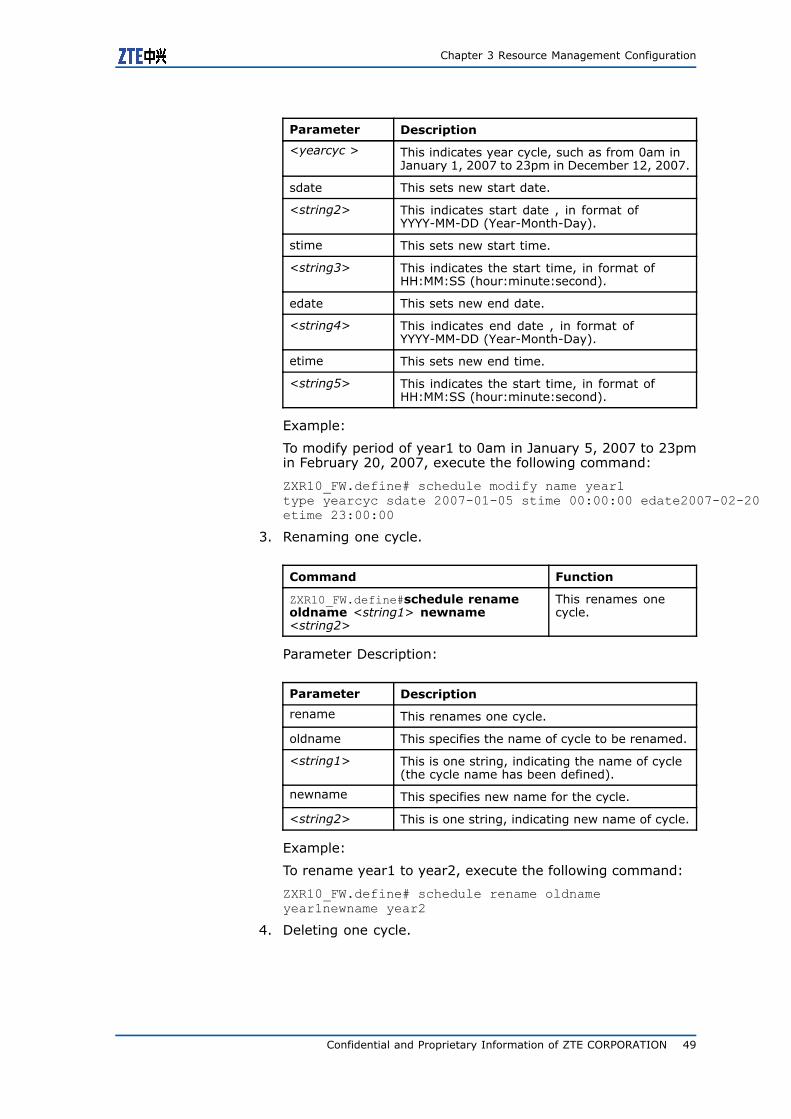
Chapter 3 Resource Management Configuration
Parameter Description
<yearcyc > This indicates year cycle, such as from 0am inJanuary 1, 2007 to 23pm in December 12, 2007.
sdate This sets new start date.
<string2> This indicates start date , in format ofYYYY-MM-DD (Year-Month-Day).
stime This sets new start time.
<string3> This indicates the start time, in format ofHH:MM:SS (hour:minute:second).
edate This sets new end date.
<string4> This indicates end date , in format ofYYYY-MM-DD (Year-Month-Day).
etime This sets new end time.
<string5> This indicates the start time, in format ofHH:MM:SS (hour:minute:second).
Example:
To modify period of year1 to 0am in January 5, 2007 to 23pmin February 20, 2007, execute the following command:
ZXR10_FW.define# schedule modify name year1type yearcyc sdate 2007-01-05 stime 00:00:00 edate2007-02-20etime 23:00:00
3. Renaming one cycle.
Command Function
ZXR10_FW.define#schedule renameoldname <string1> newname<string2>
This renames onecycle.
Parameter Description:
Parameter Description
rename This renames one cycle.
oldname This specifies the name of cycle to be renamed.
<string1> This is one string, indicating the name of cycle(the cycle name has been defined).
newname This specifies new name for the cycle.
<string2> This is one string, indicating new name of cycle.
Example:
To rename year1 to year2, execute the following command:
ZXR10_FW.define# schedule rename oldnameyear1newname year2
4. Deleting one cycle.
Confidential and Proprietary Information of ZTE CORPORATION 49
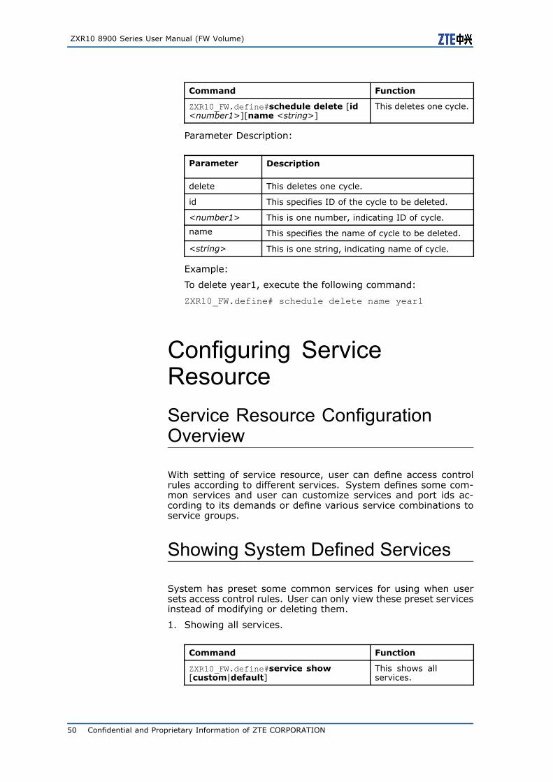
ZXR10 8900 Series User Manual (FW Volume)
Command Function
ZXR10_FW.define#schedule delete [id<number1>][name <string>]
This deletes one cycle.
Parameter Description:
Parameter Description
delete This deletes one cycle.
id This specifies ID of the cycle to be deleted.
<number1> This is one number, indicating ID of cycle.
name This specifies the name of cycle to be deleted.
<string> This is one string, indicating name of cycle.
Example:
To delete year1, execute the following command:
ZXR10_FW.define# schedule delete name year1
Configuring ServiceResourceService Resource ConfigurationOverview
With setting of service resource, user can define access controlrules according to different services. System defines some com-mon services and user can customize services and port ids ac-cording to its demands or define various service combinations toservice groups.
Showing System Defined Services
System has preset some common services for using when usersets access control rules. User can only view these preset servicesinstead of modifying or deleting them.
1. Showing all services.
Command Function
ZXR10_FW.define#service show[custom|default]
This shows allservices.
50 Confidential and Proprietary Information of ZTE CORPORATION
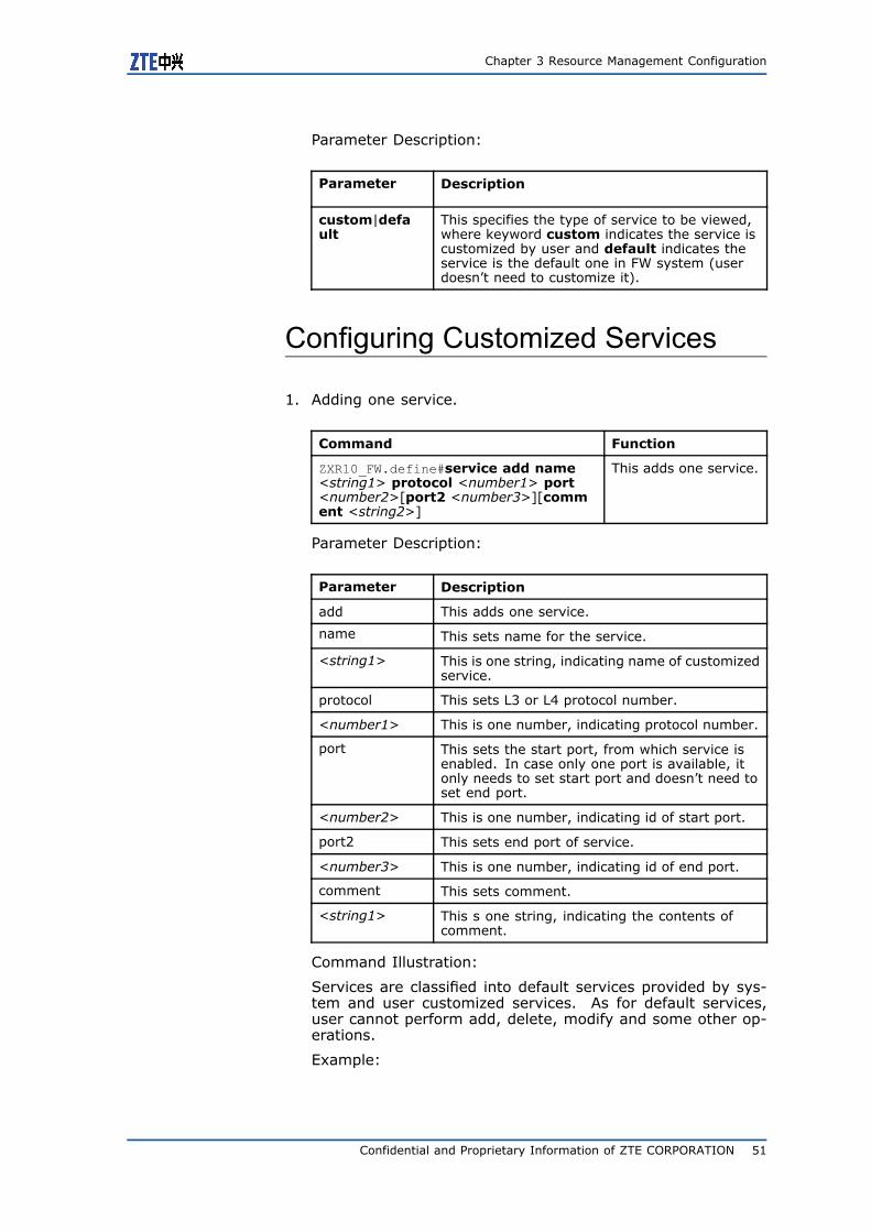
Chapter 3 Resource Management Configuration
Parameter Description:
Parameter Description
custom|default
This specifies the type of service to be viewed,where keyword custom indicates the service iscustomized by user and default indicates theservice is the default one in FW system (userdoesn’t need to customize it).
Configuring Customized Services
1. Adding one service.
Command Function
ZXR10_FW.define#service add name<string1> protocol <number1> port<number2>[port2 <number3>][comment <string2>]
This adds one service.
Parameter Description:
Parameter Description
add This adds one service.
name This sets name for the service.
<string1> This is one string, indicating name of customizedservice.
protocol This sets L3 or L4 protocol number.
<number1> This is one number, indicating protocol number.
port This sets the start port, from which service isenabled. In case only one port is available, itonly needs to set start port and doesn’t need toset end port.
<number2> This is one number, indicating id of start port.
port2 This sets end port of service.
<number3> This is one number, indicating id of end port.
comment This sets comment.
<string1> This s one string, indicating the contents ofcomment.
Command Illustration:
Services are classified into default services provided by sys-tem and user customized services. As for default services,user cannot perform add, delete, modify and some other op-erations.
Example:
Confidential and Proprietary Information of ZTE CORPORATION 51
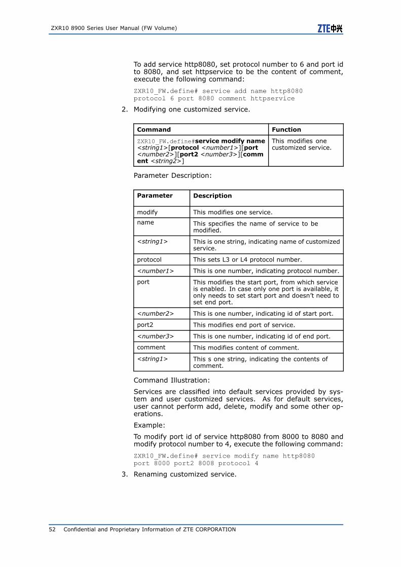
ZXR10 8900 Series User Manual (FW Volume)
To add service http8080, set protocol number to 6 and port idto 8080, and set httpservice to be the content of comment,execute the following command:
ZXR10_FW.define# service add name http8080protocol 6 port 8080 comment httpservice
2. Modifying one customized service.
Command Function
ZXR10_FW.define#service modify name<string1>[protocol <number1>][port<number2>][port2 <number3>][comment <string2>]
This modifies onecustomized service.
Parameter Description:
Parameter Description
modify This modifies one service.
name This specifies the name of service to bemodified.
<string1> This is one string, indicating name of customizedservice.
protocol This sets L3 or L4 protocol number.
<number1> This is one number, indicating protocol number.
port This modifies the start port, from which serviceis enabled. In case only one port is available, itonly needs to set start port and doesn’t need toset end port.
<number2> This is one number, indicating id of start port.
port2 This modifies end port of service.
<number3> This is one number, indicating id of end port.
comment This modifies content of comment.
<string1> This s one string, indicating the contents ofcomment.
Command Illustration:
Services are classified into default services provided by sys-tem and user customized services. As for default services,user cannot perform add, delete, modify and some other op-erations.
Example:
To modify port id of service http8080 from 8000 to 8080 andmodify protocol number to 4, execute the following command:
ZXR10_FW.define# service modify name http8080port 8000 port2 8008 protocol 4
3. Renaming customized service.
52 Confidential and Proprietary Information of ZTE CORPORATION
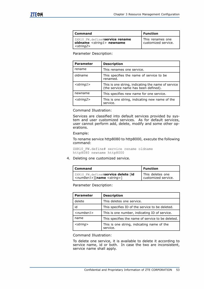
Chapter 3 Resource Management Configuration
Command Function
ZXR10_FW.define#service renameoldname <string1> newname<string2>
This renames onecustomized service.
Parameter Description:
Parameter Description
rename This renames one service.
oldname This specifies the name of service to berenamed.
<string1> This is one string, indicating the name of service(the service name has been defined).
newname This specifies new name for one service.
<string2> This is one string, indicating new name of theservice.
Command Illustration:
Services are classified into default services provided by sys-tem and user customized services. As for default services,user cannot perform add, delete, modify and some other op-erations.
Example:
To rename service http8080 to http8000, execute the followingcommand:
ZXR10_FW.define# service rename oldnamehttp8080 newname http8000
4. Deleting one customized service.
Command Function
ZXR10_FW.define#service delete [id<number1>][name <string>]
This deletes onecustomized service.
Parameter Description:
Parameter Description
delete This deletes one service.
id This specifies ID of the service to be deleted.
<number1> This is one number, indicating ID of service.
name This specifies the name of service to be deleted.
<string> This is one string, indicating name of theservice.
Command Illustration:
To delete one service, it is available to delete it according toservice name, id or both. In case the two are inconsistent,service name shall apply.
Confidential and Proprietary Information of ZTE CORPORATION 53
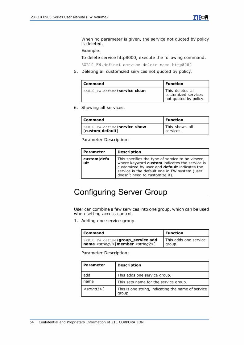
ZXR10 8900 Series User Manual (FW Volume)
When no parameter is given, the service not quoted by policyis deleted.
Example:
To delete service http8000, execute the following command:
ZXR10_FW.define# service delete name http8000
5. Deleting all customized services not quoted by policy.
Command Function
ZXR10_FW.define#service clean This deletes allcustomized servicesnot quoted by policy.
6. Showing all services.
Command Function
ZXR10_FW.define#service show[custom|default]
This shows allservices.
Parameter Description:
Parameter Description
custom|default
This specifies the type of service to be viewed,where keyword custom indicates the service iscustomized by user and default indicates theservice is the default one in FW system (userdoesn’t need to customize it).
Configuring Server Group
User can combine a few services into one group, which can be usedwhen setting access control.
1. Adding one service group.
Command Function
ZXR10_FW.define#group_service addname <string1>[member <string2>]
This adds one servicegroup.
Parameter Description:
Parameter Description
add This adds one service group.
name This sets name for the service group.
<string1>[ This is one string, indicating the name of servicegroup.
54 Confidential and Proprietary Information of ZTE CORPORATION
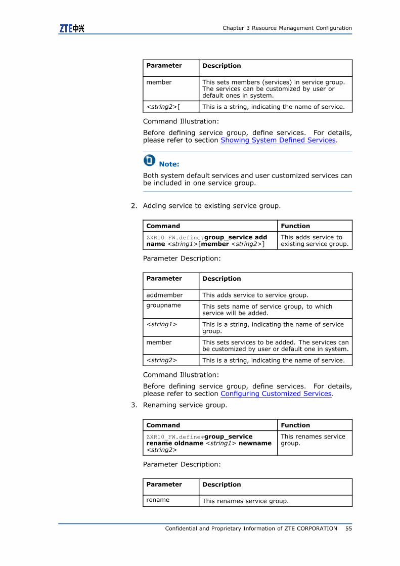
Chapter 3 Resource Management Configuration
Parameter Description
member This sets members (services) in service group.The services can be customized by user ordefault ones in system.
<string2>[ This is a string, indicating the name of service.
Command Illustration:
Before defining service group, define services. For details,please refer to section Showing System Defined Services.
Note:
Both system default services and user customized services canbe included in one service group.
2. Adding service to existing service group.
Command Function
ZXR10_FW.define#group_service addname <string1>[member <string2>]
This adds service toexisting service group.
Parameter Description:
Parameter Description
addmember This adds service to service group.
groupname This sets name of service group, to whichservice will be added.
<string1> This is a string, indicating the name of servicegroup.
member This sets services to be added. The services canbe customized by user or default one in system.
<string2> This is a string, indicating the name of service.
Command Illustration:
Before defining service group, define services. For details,please refer to section Configuring Customized Services.
3. Renaming service group.
Command Function
ZXR10_FW.define#group_servicerename oldname <string1> newname<string2>
This renames servicegroup.
Parameter Description:
Parameter Description
rename This renames service group.
Confidential and Proprietary Information of ZTE CORPORATION 55
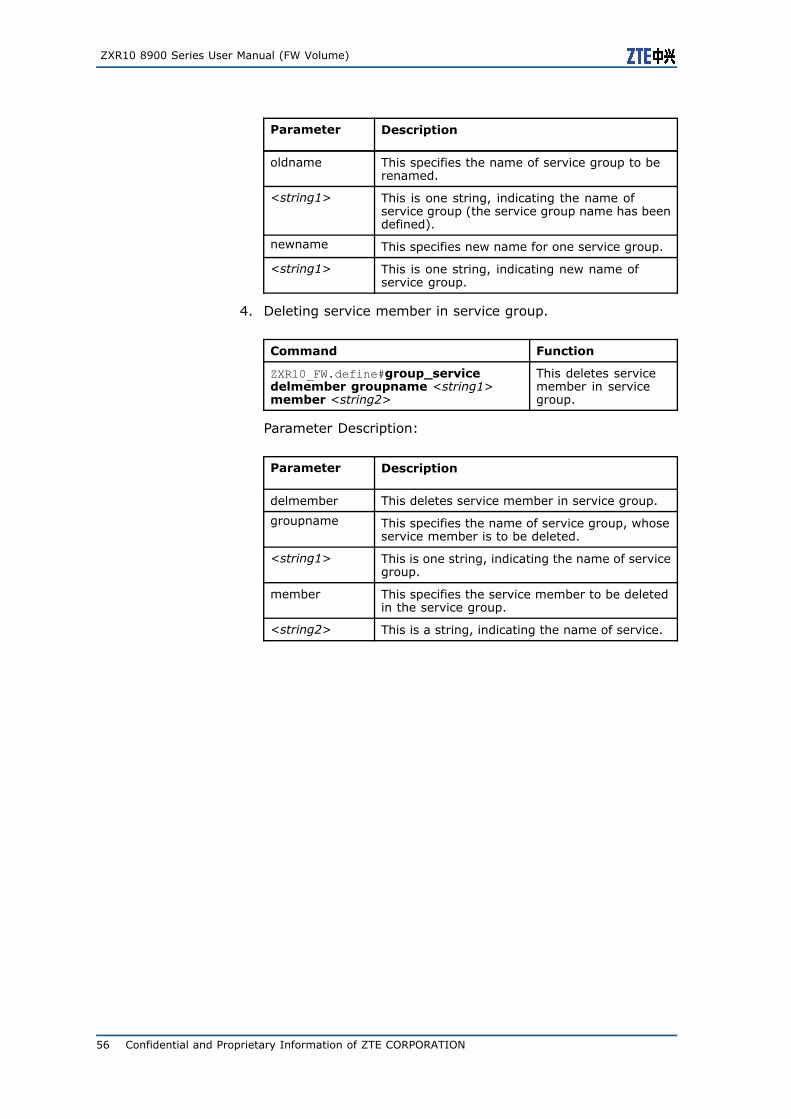
ZXR10 8900 Series User Manual (FW Volume)
Parameter Description
oldname This specifies the name of service group to berenamed.
<string1> This is one string, indicating the name ofservice group (the service group name has beendefined).
newname This specifies new name for one service group.
<string1> This is one string, indicating new name ofservice group.
4. Deleting service member in service group.
Command Function
ZXR10_FW.define#group_servicedelmember groupname <string1>member <string2>
This deletes servicemember in servicegroup.
Parameter Description:
Parameter Description
delmember This deletes service member in service group.
groupname This specifies the name of service group, whoseservice member is to be deleted.
<string1> This is one string, indicating the name of servicegroup.
member This specifies the service member to be deletedin the service group.
<string2> This is a string, indicating the name of service.
56 Confidential and Proprietary Information of ZTE CORPORATION
C h a p t e r 4
ZXR10 FW FunctionManagement
Table of Contents:ZXR10 FW Function Management Overview...........................57Configuring ZXR10 FW .......................................................58
ZXR10 FW FunctionManagement OverviewManagement to most functions of ZXR10 8900 Series Switch FWservice card is based on VLAN and implemented on main boardwith command lines. The following FW-related confutations areavailable on main board:
� Entering and exiting from FW configuration mode
� Creating and deleting fw-template
� Binding management IP
� Configuring flow recovery
� Binding slot number
� Configuring nat ip
� Configuring session
� Binding FW template for specific vlan
� Viewing management configuration
� Configuring vlan
Confidential and Proprietary Information of ZTE CORPORATION 57
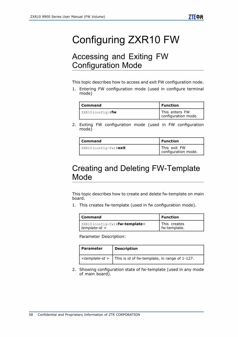
ZXR10 8900 Series User Manual (FW Volume)
Configuring ZXR10 FWAccessing and Exiting FWConfiguration Mode
This topic describes how to access and exit FW configuration node.
1. Entering FW configuration mode (used in configure terminalmode)
Command Function
ZXR10(config)#fw This enters FWconfiguration mode.
2. Exiting FW configuration mode (used in FW configurationmode)
Command Function
ZXR10(config-fw)#exit This exit FWconfiguration mode.
Creating and Deleting FW-TemplateMode
This topic describes how to create and delete fw-template on mainboard.
1. This creates fw-template (used in fw configuration mode).
Command Function
ZXR10(config-fw)#fw-template<template-id >
This createsfw-template.
Parameter Description:
Parameter Description
<template-id > This is id of fw-template, in range of 1-127.
2. Showing configuration state of fw-template (used in any modeof main board).
58 Confidential and Proprietary Information of ZTE CORPORATION
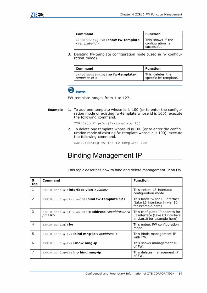
Chapter 4 ZXR10 FW Function Management
Command Function
ZXR10(config-fw)#show fw-template<template-id>
This shows if theconfiguration issuccessful.
3. Deleting fw-template configuration node (used in fw configu-ration mode).
Command Function
ZXR10(config-fw)#no fw-template<template-id >
This deletes thespecific fw-template.
Note:
FW-template ranges from 1 to 127.
Example 1. To add one template whose id is 100 (or to enter the configu-ration mode of existing fw-template whose id is 100), executethe following command.
ZXR10(config-fw)#fw-template 100
2. To delete one template whose id is 100 (or to enter the config-uration mode of existing fw-template whose id is 100), executethe following command.
ZXR10(config-fw)#no fw-template 100
Binding Management IP
This topic describes how to bind and delete management IP on FW.
Step
Command Function
1 ZXR10(config)#interface vlan <vlanid> This enters L3 interfaceconfiguration mode.
2 ZXR10(config-if-vlan10)#bind fw-template 127 This binds fw for L3 interface(take L3 interface in vlan10for example here)
3 ZXR10(config-if-vlan10)#ip address <ipaddress><ipmask>
This configures IP address forL3 interface (take L3 interfacein vlan10 for example here)
4 ZXR10(config)#fw This enters FW configurationmode.
5 ZXR10(config-fw)#bind mng-ip< ipaddress > This binds management IPwith FW.
6 ZXR10(config-fw)#show mng-ip This shows management IPof FW.
7 ZXR10(config-fw)#no bind mng-ip This deletes management IPof FW.
Confidential and Proprietary Information of ZTE CORPORATION 59
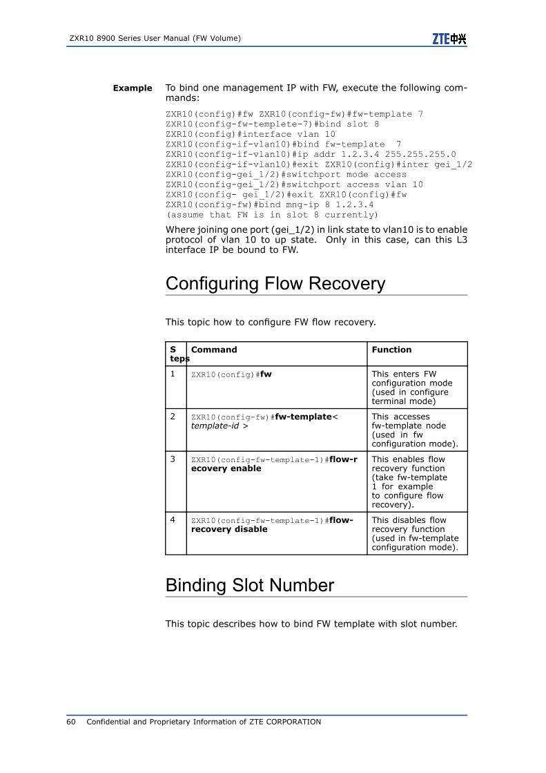
ZXR10 8900 Series User Manual (FW Volume)
Example To bind one management IP with FW, execute the following com-mands:
ZXR10(config)#fw ZXR10(config-fw)#fw-template 7ZXR10(config-fw-templete-7)#bind slot 8ZXR10(config)#interface vlan 10ZXR10(config-if-vlan10)#bind fw-template 7ZXR10(config-if-vlan10)#ip addr 1.2.3.4 255.255.255.0ZXR10(config-if-vlan10)#exit ZXR10(config)#inter gei_1/2ZXR10(config-gei_1/2)#switchport mode accessZXR10(config-gei_1/2)#switchport access vlan 10ZXR10(config- gei_1/2)#exit ZXR10(config)#fwZXR10(config-fw)#bind mng-ip 8 1.2.3.4(assume that FW is in slot 8 currently)
Where joining one port (gei_1/2) in link state to vlan10 is to enableprotocol of vlan 10 to up state. Only in this case, can this L3interface IP be bound to FW.
Configuring Flow Recovery
This topic how to configure FW flow recovery.
Steps
Command Function
1 ZXR10(config)#fw This enters FWconfiguration mode(used in configureterminal mode)
2 ZXR10(config-fw)#fw-template<template-id >
This accessesfw-template node(used in fwconfiguration mode).
3 ZXR10(config-fw-template-1)#flow-recovery enable
This enables flowrecovery function(take fw-template1 for exampleto configure flowrecovery).
4 ZXR10(config-fw-template-1)#flow-recovery disable
This disables flowrecovery function(used in fw-templateconfiguration mode).
Binding Slot Number
This topic describes how to bind FW template with slot number.
60 Confidential and Proprietary Information of ZTE CORPORATION
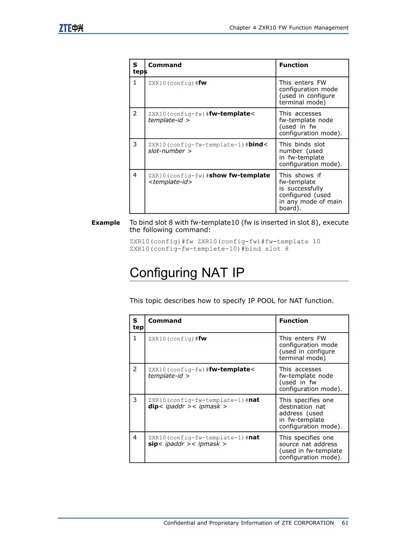
Chapter 4 ZXR10 FW Function Management
Steps
Command Function
1 ZXR10(config)#fw This enters FWconfiguration mode(used in configureterminal mode)
2 ZXR10(config-fw)#fw-template<template-id >
This accessesfw-template node(used in fwconfiguration mode).
3 ZXR10(config-fw-template-1)#bind<slot-number >
This binds slotnumber (usedin fw-templateconfiguration mode).
4 ZXR10(config-fw)#show fw-template<template-id>
This shows iffw-templateis successfullyconfigured (usedin any mode of mainboard).
Example To bind slot 8 with fw-template10 (fw is inserted in slot 8), executethe following command:
ZXR10(config)#fw ZXR10(config-fw)#fw-template 10ZXR10(config-fw-templete-10)#bind slot 8
Configuring NAT IP
This topic describes how to specify IP POOL for NAT function.
Step
Command Function
1 ZXR10(config)#fw This enters FWconfiguration mode(used in configureterminal mode)
2 ZXR10(config-fw)#fw-template<template-id >
This accessesfw-template node(used in fwconfiguration mode).
3 ZXR10(config-fw-template-1)#natdip< ipaddr >< ipmask >
This specifies onedestination nataddress (usedin fw-templateconfiguration mode).
4 ZXR10(config-fw-template-1)#natsip< ipaddr >< ipmask >
This specifies onesource nat address(used in fw-templateconfiguration mode).
Confidential and Proprietary Information of ZTE CORPORATION 61
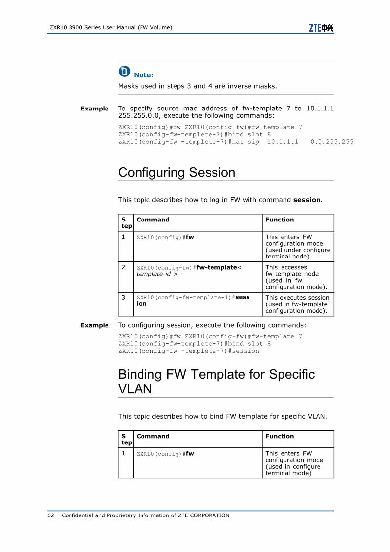
ZXR10 8900 Series User Manual (FW Volume)
Note:
Masks used in steps 3 and 4 are inverse masks.
Example To specify source mac address of fw-template 7 to 10.1.1.1255.255.0.0, execute the following commands:
ZXR10(config)#fw ZXR10(config-fw)#fw-template 7ZXR10(config-fw-templete-7)#bind slot 8ZXR10(config-fw -templete-7)#nat sip 10.1.1.1 0.0.255.255
Configuring Session
This topic describes how to log in FW with command session.
Step
Command Function
1 ZXR10(config)#fw This enters FWconfiguration mode(used under configureterminal node)
2 ZXR10(config-fw)#fw-template<template-id >
This accessesfw-template node(used in fwconfiguration mode).
3 ZXR10(config-fw-template-1)#session
This executes session(used in fw-templateconfiguration mode).
Example To configuring session, execute the following commands:
ZXR10(config)#fw ZXR10(config-fw)#fw-template 7ZXR10(config-fw-templete-7)#bind slot 8ZXR10(config-fw -templete-7)#session
Binding FW Template for SpecificVLAN
This topic describes how to bind FW template for specific VLAN.
Step
Command Function
1 ZXR10(config)#fw This enters FWconfiguration mode(used in configureterminal mode)
62 Confidential and Proprietary Information of ZTE CORPORATION
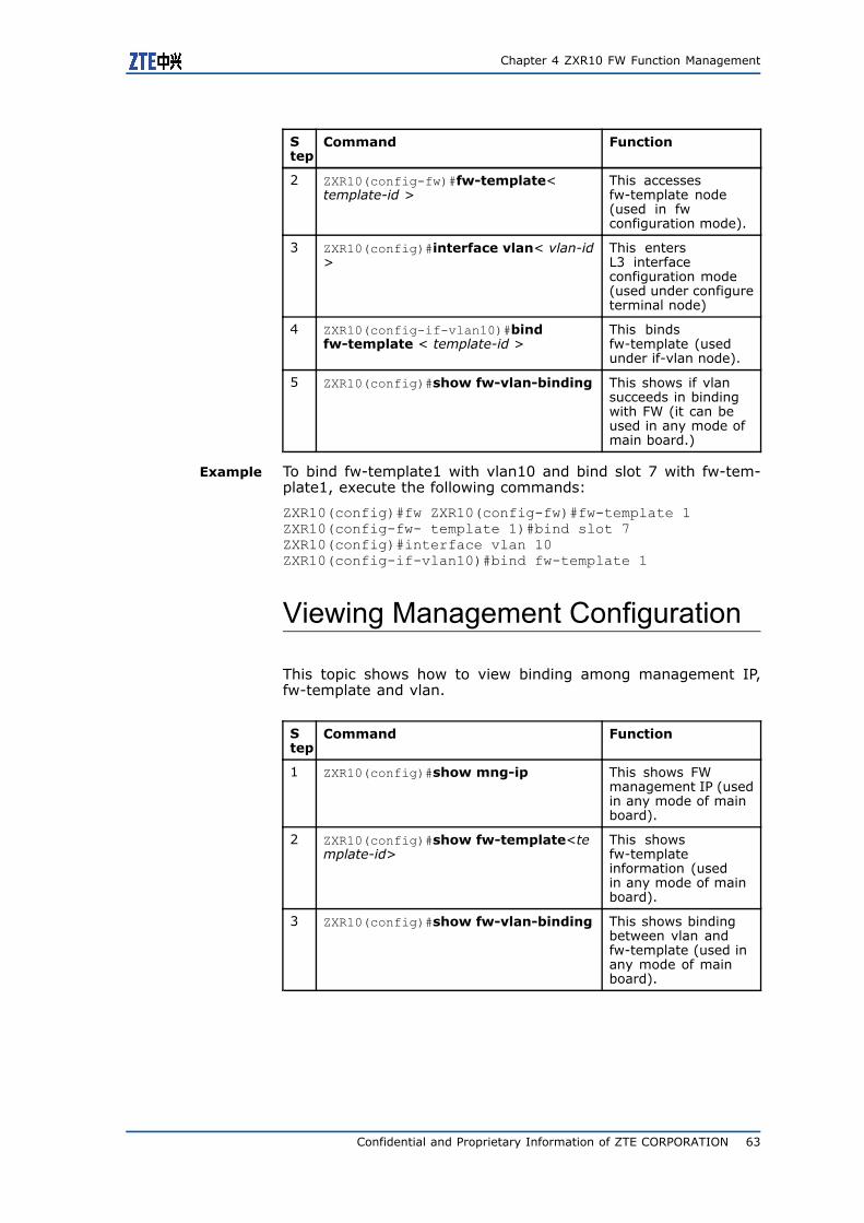
Chapter 4 ZXR10 FW Function Management
Step
Command Function
2 ZXR10(config-fw)#fw-template<template-id >
This accessesfw-template node(used in fwconfiguration mode).
3 ZXR10(config)#interface vlan< vlan-id>
This entersL3 interfaceconfiguration mode(used under configureterminal node)
4 ZXR10(config-if-vlan10)#bindfw-template < template-id >
This bindsfw-template (usedunder if-vlan node).
5 ZXR10(config)#show fw-vlan-binding This shows if vlansucceeds in bindingwith FW (it can beused in any mode ofmain board.)
Example To bind fw-template1 with vlan10 and bind slot 7 with fw-tem-plate1, execute the following commands:
ZXR10(config)#fw ZXR10(config-fw)#fw-template 1ZXR10(config-fw- template 1)#bind slot 7ZXR10(config)#interface vlan 10ZXR10(config-if-vlan10)#bind fw-template 1
Viewing Management Configuration
This topic shows how to view binding among management IP,fw-template and vlan.
Step
Command Function
1 ZXR10(config)#show mng-ip This shows FWmanagement IP (usedin any mode of mainboard).
2 ZXR10(config)#show fw-template<template-id>
This showsfw-templateinformation (usedin any mode of mainboard).
3 ZXR10(config)#show fw-vlan-binding This shows bindingbetween vlan andfw-template (used inany mode of mainboard).
Confidential and Proprietary Information of ZTE CORPORATION 63
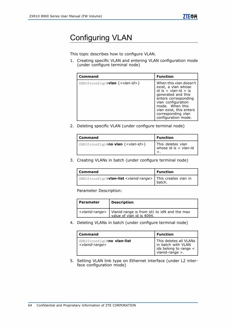
ZXR10 8900 Series User Manual (FW Volume)
Configuring VLAN
This topic describes how to configure VLAN.
1. Creating specific VLAN and entering VLAN configuration mode(under configure terminal node)
Command Function
ZXR10(config)#vlan {<vlan-id>} When this vlan doesn’texist, a vlan whoseid is < vlan-id > isgenerated and thisenters correspondingvlan configurationmode. When thisvlan exist, this enterscorresponding vlanconfiguration mode.
2. Deleting specific VLAN (under configure terminal node)
Command Function
ZXR10(config)#no vlan {<vlan-id>} This deletes vlanwhose id is < vlan-id>.
3. Creating VLANs in batch (under configure terminal node)
Command Function
ZXR10(config)#vlan-list<vlanid-range> This creates vlan inbatch.
Parameter Description:
Parameter Description
<vlanid-range> Vlanid-range is from id1 to idN and the maxvalue of vlan id is 4094.
4. Deleting VLANs in batch (under configure terminal node)
Command Function
ZXR10(config)#no vlan-list<vlanid-range>
This deletes all VLANsin batch with VLANids belong to range <vlanid-range >.
5. Setting VLAN link type on Ethernet interface (under L2 inter-face configuration mode)
64 Confidential and Proprietary Information of ZTE CORPORATION
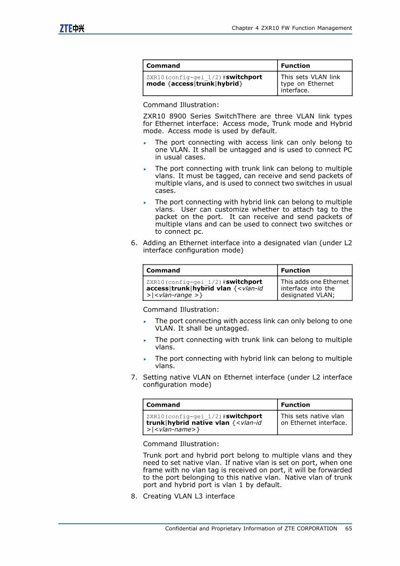
Chapter 4 ZXR10 FW Function Management
Command Function
ZXR10(config-gei_1/2)#switchportmode {access|trunk|hybrid}
This sets VLAN linktype on Ethernetinterface.
Command Illustration:
ZXR10 8900 Series SwitchThere are three VLAN link typesfor Ethernet interface: Access mode, Trunk mode and Hybridmode. Access mode is used by default.
� The port connecting with access link can only belong toone VLAN. It shall be untagged and is used to connect PCin usual cases.
� The port connecting with trunk link can belong to multiplevlans. It must be tagged, can receive and send packets ofmultiple vlans, and is used to connect two switches in usualcases.
� The port connecting with hybrid link can belong to multiplevlans. User can customize whether to attach tag to thepacket on the port. It can receive and send packets ofmultiple vlans and can be used to connect two switches orto connect pc.
6. Adding an Ethernet interface into a designated vlan (under L2interface configuration mode)
Command Function
ZXR10(config-gei_1/2)#switchportaccess|trunk|hybrid vlan {<vlan-id>|<vlan-range >}
This adds one Ethernetinterface into thedesignated VLAN;
Command Illustration:
� The port connecting with access link can only belong to oneVLAN. It shall be untagged.
� The port connecting with trunk link can belong to multiplevlans.
� The port connecting with hybrid link can belong to multiplevlans.
7. Setting native VLAN on Ethernet interface (under L2 interfaceconfiguration mode)
Command Function
ZXR10(config-gei_1/2)#switchporttrunk|hybrid native vlan {<vlan-id>|<vlan-name>}
This sets native vlanon Ethernet interface.
Command Illustration:
Trunk port and hybrid port belong to multiple vlans and theyneed to set native vlan. If native vlan is set on port, when oneframe with no vlan tag is received on port, it will be forwardedto the port belonging to this native vlan. Native vlan of trunkport and hybrid port is vlan 1 by default.
8. Creating VLAN L3 interface
Confidential and Proprietary Information of ZTE CORPORATION 65
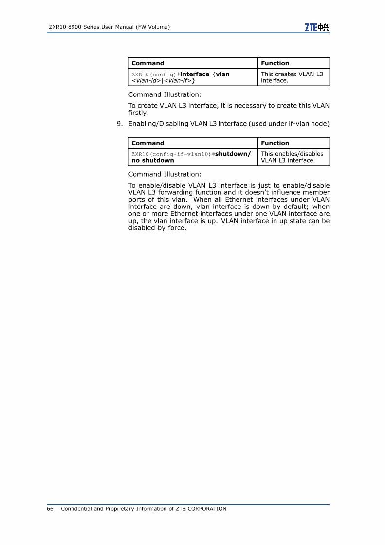
ZXR10 8900 Series User Manual (FW Volume)
Command Function
ZXR10(config)#interface {vlan<vlan-id>|<vlan-if>}
This creates VLAN L3interface.
Command Illustration:
To create VLAN L3 interface, it is necessary to create this VLANfirstly.
9. Enabling/Disabling VLAN L3 interface (used under if-vlan node)
Command Function
ZXR10(config-if-vlan10)#shutdown/no shutdown
This enables/disablesVLAN L3 interface.
Command Illustration:
To enable/disable VLAN L3 interface is just to enable/disableVLAN L3 forwarding function and it doesn’t influence memberports of this vlan. When all Ethernet interfaces under VLANinterface are down, vlan interface is down by default; whenone or more Ethernet interfaces under one VLAN interface areup, the vlan interface is up. VLAN interface in up state can bedisabled by force.
66 Confidential and Proprietary Information of ZTE CORPORATION
C h a p t e r 5
Packet Filtering andAccess Control RuleConfiguration
Table of Contents:Configuring Packet Filtering Policy........................................67Configuring Access Control Rules .........................................76Configuring IDS Interaction ................................................86
Configuring Packet FilteringPolicyPacket Filtering Overview
By reading this chapter, user can learn how to control data flow bysetting packet block policy and access control rule.
This chapter has the following content:
� Packet block policy: This part describes how to control L2/3access by setting packet block policy.
� Access control rule: This part describes how to control L3-L7access by setting access control rule.
Configuring Packet Filtering Policy
This topic describes basic configuration commands and configura-tion examples of packet filtering policy.
Commands introduced in this topic are used to set packet filteringrule, control access of received IP packets, filter illegal packets orthose denied by rules, and provide protection in the case that GWsystem doesn’t join GW module.
To access this command module, execute the following command:
Confidential and Proprietary Information of ZTE CORPORATION 67
ZXR10 8900 Series User Manual (FW Volume)
#pf
To exit from this command module, execute the following com-mand:
#exit
1. Setting default packet filtering rule.
Command Function
ZXR10_FW.pf #rule set default action<accept|reject> log<yes|no>
This sets defaultpacket filtering rule.
Parameter Description:
Parameter Description
accept|reject permit|deny
log This specifies whether to record it in the log.
yes|no Yes|No
Example:
To set default packet filtering rule to permit and not record itinto log, execute the following command:
ZXR10_FW.pf # rule set default action accept log no
2. Adding one IP packet filtering rule.
Command Function
ZXR10_FW.pf #rule add action <accept|reject> l2protocol <ip|0800>[area<string1>][log <yes|no>][smac<string2>][dmac <string3>][l3protocol<all|0|tcp|6|udp|17|icmp|1|igmp|2|number>][sip <string4>][ dip<string5>][sport <number1>][dport<number2>][ sport_end <number3>][dport_end <number4>]
This adds one IPpacket filtering rule.
Parameter Description:
Parameter Description
add This adds one packet filtering rule.
action This is the action to packet meeting rules:permit or deny
accept|reject permit|deny
l2protocol This is the L2 protocol type used by packet.
ip|0800 IP protocol|IP protocol number
area This specifies area resource.
68 Confidential and Proprietary Information of ZTE CORPORATION
Chapter 5 Packet Filtering and Access Control Rule Configuration
Parameter Description
<string1> This is one string, which must be onepredefined area resource.
log This specifies whether to record it into log.
yes|no Yes|No
smac This sets source mac address.
<string2> This is one standard mac address string.
dmac This sets destination mac address.
<string3> This is one standard mac address string.
l3protocol This is the L3 protocol type used by packet.
all|0|tcp|6|udp|17|icmp|1|igmp|2|number
All protocols/all protocols/TCP protocol/TCPprotocol/UDP protocol/UDP protocol/ICMPprotocol/ICMP protocol/IGMP protocol/Userinputs specified protocol number
sip This specifies source address, which mustbe one predefined address.
<string4> This is one string.
dip This specifies destination address, whichmust be one predefined address.
<string5> This is one string.
sport This specifies source start port id.
<number1> This is one number.
sport_end This specifies source end port id.
<number2> This is one number.
dport This specifies destination start port id.
<number3> This is one number.
dport_end This specifies destination end port id.
<number4> This is one number.
Example:
To permit the device whose source MAC address is00:50:04:C3:B0:31 to access the device whose destinationip is doc_server and destination port id is 8000, execute thefollowing command, where doc_server is predefined address.
ZXR10_FW.pf # rule add action accept smac00:50:04:C3:B0:31 dip doc_server dport 8000
3. Adding one ARP/RARP/IPX packet filtering rule.
Command Function
ZXR10_FW.pf #rule add action<accept|reject> l2protocol <arp|0806|rarp|8035|ipx|8137>[log<yes|no>][area<string>][smac < string 2>][dmac <string 3>]
This adds oneARP/RARP/IPX packetfiltering rule.
Parameter Description:
Confidential and Proprietary Information of ZTE CORPORATION 69
ZXR10 8900 Series User Manual (FW Volume)
Parameter Description
add This adds one packet filtering rule.
action This is the action to packet meeting rules:permit or deny
accept|reject permit|deny
l2protocol This is the L2 protocol type used by packet.
arp|0806|rarp|8035|ipx|8137
ARP| ARP protocol number|RARP| RARPprotocol number|IPX|IPX protocol number
log This specifies whether to record it into log.
yes|no Yes|No
area This specifies area resource.
<string1> This is one string, which must be onepredefined area resource.
smac This sets source mac address.
<string2> This is one standard mac address string.
dmac This sets destination mac address.
<string3> This is one standard mac address string.
Example:
To add arp accept rule to area_eth1 and record it into log,execute the following command:
ZXR10_FW.pf # rule add action accept l2protocolarp smac 00:50:04:C3:B0:31
4. Adding one L3 protocol packet filtering rule.
Command Function
ZXR10_FW.pf #rule add action<accept|reject> l3protocol <number>[log<yes|no>][area <string1>][smac <string2 >][dmac < string3>]
This adds one L3protocol packetfiltering rule.
Parameter Description:
Parameter Description
add This adds one packet filtering rule.
action This is the action to packet meeting rules:permit or deny
accept|reject permit|deny
l3protocol This is the L3 protocol type used by packet.
<number> This is the protocol number.
log This specifies whether to record it into log.
yes|no Yes|No
70 Confidential and Proprietary Information of ZTE CORPORATION
Chapter 5 Packet Filtering and Access Control Rule Configuration
Parameter Description
area This specifies area resource.
<string1> This is one string, which must be onepredefined area resource.
smac This sets source mac address.
<string2> This is one standard mac address string.
dmac This sets destination mac address.
<string3> This is one standard mac address string.
Command Illustration:
To reject TCP packets passing through and not record it intolog, execute the following command:
ZXR10_FW.pf # rule add action reject l3protocol 6 log no
5. Modifying one IP packet filtering rule.
Command Function
ZXR10_FW.pf #rule modify id <numbe1>[action <accept| reject>][l2protocol <ip|0800>][area<string1>][log <yes|no>][smac<string2>][dmac <string3>][l3protocol<all|0|tcp|6|udp|17|icmp|1|igmp|2|number>][sip <string4>][ dip<string5>][sport <number2>][dport<number3>][ sport_end <numbe4>][dport_end <number5>]
This modifies one IPpacket filtering rule.
Parameter Description:
Parameter Description
modify This modifies one packet filtering rule.
id This is rule id.
< numbe1> This is one number.
action This is the action to packet meeting rules:permit or deny.
accept|reject permit|deny
l2protocol This is the L2 protocol type used by packet.
ip|0800 IP protocol|IP protocol number
area This specifies area resource.
<string1> This is one string, which must be onepredefined area resource.
log This specifies whether to record it into log.
yes|no Yes|No
Confidential and Proprietary Information of ZTE CORPORATION 71
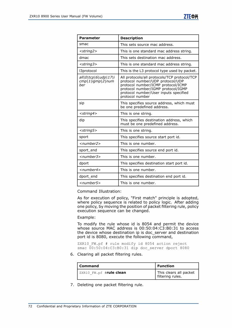
ZXR10 8900 Series User Manual (FW Volume)
Parameter Description
smac This sets source mac address.
<string2> This is one standard mac address string.
dmac This sets destination mac address.
<string3> This is one standard mac address string.
l3protocol This is the L3 protocol type used by packet.
all|0|tcp|6|udp|17|icmp|1|igmp|2|number
All protocols/all protocols/TCP protocol/TCPprotocol number/UDP protocol/UDPprotocol number/ICMP protocol/ICMPprotocol number/IGMP protocol/IGMPprotocol number/User inputs specifiedprotocol number
sip This specifies source address, which mustbe one predefined address.
<string4> This is one string.
dip This specifies destination address, whichmust be one predefined address.
<string5> This is one string.
sport This specifies source start port id.
<number2> This is one number.
sport_end This specifies source end port id.
<number3> This is one number.
dport This specifies destination start port id.
<number4> This is one number.
dport_end This specifies destination end port id.
<number5> This is one number.
Command Illustration:
As for execution of policy, "First match" principle is adopted,where policy sequence is related to policy logic. After addingone policy, by moving the position of packet filtering rule, policyexecution sequence can be changed.
Example:
To modify the rule whose id is 8054 and permit the devicewhose source MAC address is 00:50:04:C3:B0:31 to accessthe device whose destination ip is doc_server and destinationport id is 8080, execute the following command,
ZXR10_FW.pf # rule modify id 8054 action rejectsmac 00:50:04:C3:B0:31 dip doc_server dport 8080
6. Clearing all packet filtering rules.
Command Function
ZXR10_FW.pf #rule clean This clears all packetfiltering rules.
7. Deleting one packet filtering rule.
72 Confidential and Proprietary Information of ZTE CORPORATION
Chapter 5 Packet Filtering and Access Control Rule Configuration
Command Function
ZXR10_FW.pf #rule delete id <number> This deletes onepacket filtering rule.
Parameter Description:
Parameter Description
<number> This is rule id.
8. Viewing packet filtering rule.
Command Function
ZXR10_FW.pf #rule show This shows packetfiltering rule.
Packet Filtering Policy ConfigurationExample
Packet Filtering Policy Configuration ExampleOne
The most basic function of FW is to control communication betweenintranet and extranet. MAC address can be used to directly identifyone network device. FW card supports to filter packets based onMAC address. Only packets whose MAC address meets packet fil-tering rule can pass through FW and access destination area. WithMAC address filtering technology, only authorized MAC addresscan access network resources. In the Figure 1, only forbid thehost in Area_Vlan2 and whose MAC address is 00:50:04:C3:B0:31to access document server (port 8000 in 192.168.83.234/24) inArea_Vlan1.
Confidential and Proprietary Information of ZTE CORPORATION 73
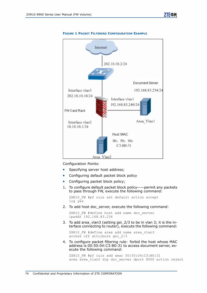
ZXR10 8900 Series User Manual (FW Volume)
FIGURE 1 PACKET FILTERING CONFIGURATION EXAMPLE
Configuration Points:
� Specifying server host address;
� Configuring default packet block policy
� Configuring packet block policy;
1. To configure default packet block policy——permit any packetsto pass through FW, execute the following command:
ZXR10_FW #pf rule set default action acceptlog yes
2. To add host doc_server, execute the following command:
ZXR10_FW #define host add name doc_serveripaddr 192.168.83.234
3. To add area_vlan3 (setting gei_2/3 to be in vlan 3; it is the in-terface connecting to router), execute the following command:
ZXR10_FW #define area add name area_vlan3access off attribute gei_2/3
4. To configure packet filtering rule: forbid the host whose MACaddress is 00:50:04:C3:B0:31 to access document server, ex-ecute the following command:
ZXR10_FW #pf rule add smac 00:50:04:C3:B0:31area area_vlan2 dip doc_server dport 8000 action reject
74 Confidential and Proprietary Information of ZTE CORPORATION
Chapter 5 Packet Filtering and Access Control Rule Configuration
Notes:
� Make sure that area attribute and access control rule specifyto forbid this host to access document sever.
� Hexadecimal digit letter in MAC address shall be upper case.For example, if MAC address 00:50:04:C3:B0:31 is wrongly in-put to 00:50:04:c3:b0:31, system will prompt error message.
� If source MAC address and source IP address are input whendefining packet filtering policy, this rule takes effect only whenboth MAC address and IP address of host match this condition.
� To forbid accessing some ports of destination host, set rangeon destination port if port ids are continuous, or it needs to setcorresponding packet block policy to each port. If there is onlyone port, it is ok to only input start port id or set the samevalue for start and end port ids. In this example, it is set to8000-8000.
� It is not recommended to input MAC address. If destinationMAC address needs to be input, it must be MAC address of FW(corresponding to this area) physical interface and cannot beother values.
Packet Filtering Policy Configuration ExampleTwo
Disable port 8000 in 192.168.83.234 to 10.10.10.0/24. That’s tosay, users of all network segments except for 10.10.10.0/24 canaccess port 800 in 192.168.83.234.
Configuration Points:
� Defining server host address resource and subnet address re-source;
� Configuring default packet block policy;
� Configuring packet block policy;
1. Configuring default packet block policy——permit any packetsto pass through FW.
ZXR10_FW #pf rule set default actionaccept log yes
2. Adding host address resource doc_server.
ZXR10_FW #define host add name doc_serveripaddr 192.168.83.234
3. Adding subnet address resource market department.
ZXR10_FW #define subnet add name marketipaddr 10.10.10.0 mask 255.255.255.0
4. Adding packet block policy and forbidding market accessingport 8000 of document server.
ZXR10_FW #pf rule add sip market dipdoc_server dport 8000 action reject
Confidential and Proprietary Information of ZTE CORPORATION 75
ZXR10 8900 Series User Manual (FW Volume)
Configuring Access ControlRulesAccess Control Rule Overview
As for access control rule, FW card permits or denies the packetsmatching access control rule to pass through.
After receiving one packet, FW will match it with all rules in ACL se-quentially. Once matched rule is found, FW processes this packetaccording to operation (permit or drop) specified by this policy andnot check default area attribute. In case matched access rule isunavailable, FW card will process this packet according to defaultattribute (permit or deny) of the area where destination interfacelocates.
Before querying access control rule, FW card will query if thepacket matches destination address translation rule. If the packetmatches destination address translation rule, FW card will trans-late destination IP address of received packet to preset IP address(actual IP address in usual cases). Therefore, when settingaccess control rule, system uses actual source and destinationaddresses (destination address after translation) to set accessrule; meanwhile, system supports to set access rule according todestination address before translation. In this case, packet willmatch access control rule according to destination address beforetranslation.
By defining access control rule, that is defining match rule ofpacket, FW card can identify and match packet from variousaspects such as area, VLAN, address, user, connection and time.Source and destination of access control rule can be presetVLAN/area or one or more address resources and user groupresources.
Configuring Access Control Rule
This topic describes configuration commands and configuration ex-amples of access control rule.
User can control L3-L7 access flexibly and powerfully by settingaccess control rule. FW card can identify and match packet fromvarious aspects such as area, VLAN, address, user, connection andtime. What’s more, FW card can perform deep data detection andfiltering for various application layer protocols. Similar to packetfiltering policy, packet matches access control rules sequentially.However, there is no default rule for access control rule. That’s tosay, if no Deny All rule is attached to the end of ACL, system willprocess this packet according to default attribute (permit or deny)of area where destination interface locates.
To access this command module, execute the following command:
#firewall
76 Confidential and Proprietary Information of ZTE CORPORATION
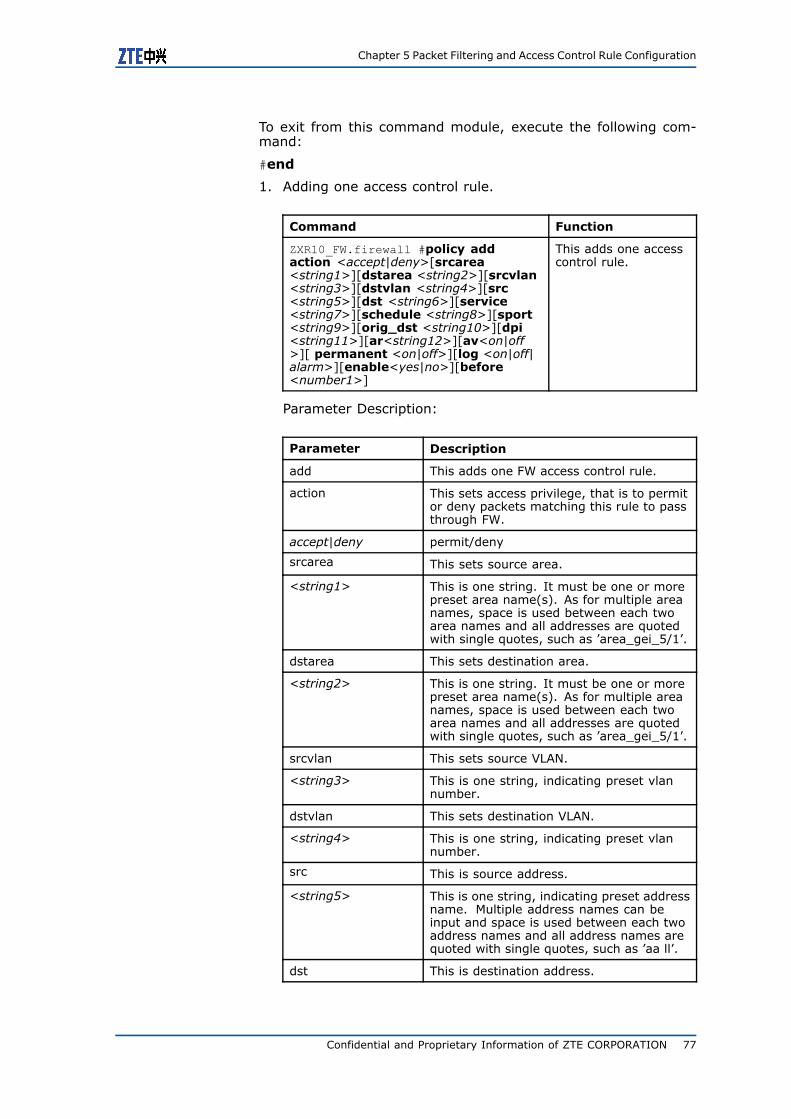
Chapter 5 Packet Filtering and Access Control Rule Configuration
To exit from this command module, execute the following com-mand:
#end
1. Adding one access control rule.
Command Function
ZXR10_FW.firewall #policy addaction <accept|deny>[srcarea<string1>][dstarea <string2>][srcvlan<string3>][dstvlan <string4>][src<string5>][dst <string6>][service<string7>][schedule <string8>][sport<string9>][orig_dst <string10>][dpi<string11>][ar<string12>][av<on|off>][ permanent <on|off>][log <on|off|alarm>][enable<yes|no>][before<number1>]
This adds one accesscontrol rule.
Parameter Description:
Parameter Description
add This adds one FW access control rule.
action This sets access privilege, that is to permitor deny packets matching this rule to passthrough FW.
accept|deny permit/deny
srcarea This sets source area.
<string1> This is one string. It must be one or morepreset area name(s). As for multiple areanames, space is used between each twoarea names and all addresses are quotedwith single quotes, such as ’area_gei_5/1’.
dstarea This sets destination area.
<string2> This is one string. It must be one or morepreset area name(s). As for multiple areanames, space is used between each twoarea names and all addresses are quotedwith single quotes, such as ’area_gei_5/1’.
srcvlan This sets source VLAN.
<string3> This is one string, indicating preset vlannumber.
dstvlan This sets destination VLAN.
<string4> This is one string, indicating preset vlannumber.
src This is source address.
<string5> This is one string, indicating preset addressname. Multiple address names can beinput and space is used between each twoaddress names and all address names arequoted with single quotes, such as ’aa ll’.
dst This is destination address.
Confidential and Proprietary Information of ZTE CORPORATION 77
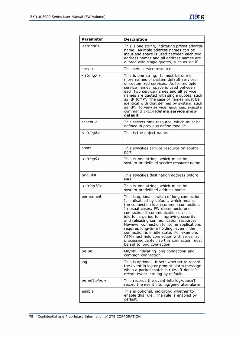
ZXR10 8900 Series User Manual (FW Volume)
Parameter Description
<string6> This is one string, indicating preset addressname. Multiple address names can beinput and space is used between each twoaddress names and all address names arequoted with single quotes, such as ’aa ll’.
service This sets service resource.
<string7> This is one string. It must be one ormore names of system default servicesor customized services. As for multipleservice names, space is used betweeneach two service names and all servicenames are quoted with single quotes, suchas ’IP ICMP’. The case of names must beidentical with that defined by system, suchas ’IP’. To view service resources, executecommand ZXR10#define service showdefault.
schedule This selects time resource, which must bedefined in previous define module.
<string8> This is the object name.
sport This specifies service resource on sourceport.
<string9> This is one string, which must besystem-predefined service resource name.
orig_dst This specifies destination address beforeNAT.
<string10> This is one string, which must besystem-predefined address name.
permanent This is optional. switch of long connection.It is disabled by default, which meansthe connection is an common connection.In usual cases, FW disconnects oneconnection if communication on it isidle for a period for improving securityand releasing communication resources.However connection for some applicationsrequires long-time holding, even if theconnection is in idle state. For example,ATM must hold connection with server atprocessing center, so this connection mustbe set to long connection.
on|off On/off, indicating long connection andcommon connection.
log This is optional. It sets whether to recordthe event in log or prompt alarm messagewhen a packet matches rule. It doesn’trecord event into log by default.
on|off| alarm This records the event into log/doesn’trecord the event into log/generates alarm.
enable This is optional, indicating whether toenable this rule. The rule is enabled bydefault.
78 Confidential and Proprietary Information of ZTE CORPORATION
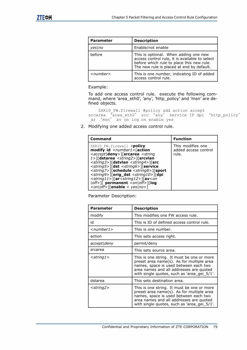
Chapter 5 Packet Filtering and Access Control Rule Configuration
Parameter Description
yes|no Enable/not enable
before This is optional. When adding one newaccess control rule, it is available to selectbefore which rule to place this new rule.The new rule is placed at end by default.
<number> This is one number, indicating ID of addedaccess control rule.
Example:
To add one access control rule. execute the following com-mand, where ’area_eth0’, ’any’, ’http_policy’ and ’msn’ are de-fined objects.
ZXR10_FW.firewall #policy add action acceptsrcarea ‘area_eth0’ src ‘any’ service IP dpi ‘http_policy’ar ‘msn’ av on log on enable yes
2. Modifying one added access control rule.
Command Function
ZXR10_FW.firewall #policymodify id <number1>[action<accept|deny>][srcarea <string1>][dstarea <string2>][srcvlan<string3>][dstvlan <string4>][src<string5>][dst <string6>][service<string7>][schedule <string8>][sport<string9>][orig_dst <string10>][dpi<string11>][ar<string12>][av<on|off>][ permanent <on|off>][log<on|off>][enable < yes|no>]
This modifies oneadded access controlrule.
Parameter Description:
Parameter Description
modify This modifies one FW access rule.
id This is ID of defined access control rule.
<number1> This is one number.
action This sets access right.
accept|deny permit/deny
srcarea This sets source area.
<string1> This is one string. It must be one or morepreset area name(s). As for multiple areanames, space is used between each twoarea names and all addresses are quotedwith single quotes, such as ’area_gei_5/1’.
dstarea This sets destination area.
<string2> This is one string. It must be one or morepreset area name(s). As for multiple areanames, space is used between each twoarea names and all addresses are quotedwith single quotes, such as ’area_gei_5/1’.
Confidential and Proprietary Information of ZTE CORPORATION 79

ZXR10 8900 Series User Manual (FW Volume)
Parameter Description
srcvlan This sets source VLAN.
<string3> This is one string, indicating preset vlannumber.
dstvlan This sets destination VLAN.
<string4> This is one string, indicating preset vlannumber.
src This is source address.
<string5> This is one string, indicating preset addressname. Multiple address names can beinput and space is used between each twoaddress names and all address names arequoted with single quotes, such as ’aa ll’.
dst This is destination address.
<string6> This is one string, indicating preset addressname. Multiple address names can beinput and space is used between each twoaddress names and all address names arequoted with single quotes, such as ’aa ll’.
service This sets service resource.
<string7> This is one string. It must be one ormore names of system default servicesor customized services. As for multipleservice names, space is used betweeneach two service names and all servicenames are quoted with single quotes, suchas ’IP ICMP’. The case of names must beidentical with that defined by system, suchas ’IP’. To view service resources, executecommand ZXR10#define service showdefault.
schedule This selects time resource, which must bedefined in previous define module.
<string8> This is the object name.
sport This specifies service resource on sourceport.
<string9> This is one string, which must besystem-predefined service resource name.
orig_dst This specifies destination address beforeNAT.
<string10> This is one string, which must besystem-predefined address name.
dpi This sets DPI object.
<string11> This specifies object name, which must bedefined in previous DPI module and onlyone name can be selected.
ar This sets application identification policy.
80 Confidential and Proprietary Information of ZTE CORPORATION
Chapter 5 Packet Filtering and Access Control Rule Configuration
Parameter Description
<string12> This specifies object name, which must bedefined in content filtering module and onlyone name can be selected.
av This sets whether to enable anti-virusmodule.
on|off Enable/disable, disable by default.
permanent This is the switch of long connection.
on|off on/off
log It sets whether to record the event in logor prompt alarm message when a packetmatches rule. It doesn’t record event intolog by default.
on|off This records the event into log/doesn’trecord the event into log/generates alarm.
enable This specifies whether to enable this rule.
yes|no Enable/Disable
Example:
To modify one access control rule. execute the following com-mand, where ’area_eth0’, ’any’, ’http_policy’ and ’msn’ are de-fined objects.
ZXR10_FW . firewall #policy modify id 8048 actionaccept srcarea ‘area_eth0’ src ‘any’ service IP dpi‘http_policy’ar ‘msn’ av on log on enable yes
3. Deleting one access control rule. execute the following com-mand,
Command Function
ZXR10_FW.firewall #policy delete id<number1>
This deletes oneaccess control rule.execute the followingcommand.
Parameter Description:
Parameter Description
<number1> This is one string, which must be ID ofpredefined rule.
Example:
To delete one access control rule whose id is 8503, execute thefollowing command:
ZXR10_FW.firewall #policy delete id 8503
Confidential and Proprietary Information of ZTE CORPORATION 81
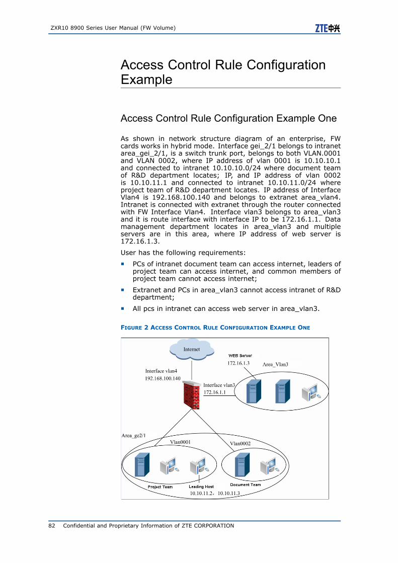
ZXR10 8900 Series User Manual (FW Volume)
Access Control Rule ConfigurationExample
Access Control Rule Configuration Example One
As shown in network structure diagram of an enterprise, FWcards works in hybrid mode. Interface gei_2/1 belongs to intranetarea_gei_2/1, is a switch trunk port, belongs to both VLAN.0001and VLAN 0002, where IP address of vlan 0001 is 10.10.10.1and connected to intranet 10.10.10.0/24 where document teamof R&D department locates; IP, and IP address of vlan 0002is 10.10.11.1 and connected to intranet 10.10.11.0/24 whereproject team of R&D department locates. IP address of InterfaceVlan4 is 192.168.100.140 and belongs to extranet area_vlan4.Intranet is connected with extranet through the router connectedwith FW Interface Vlan4. Interface vlan3 belongs to area_vlan3and it is route interface with interface IP to be 172.16.1.1. Datamanagement department locates in area_vlan3 and multipleservers are in this area, where IP address of web server is172.16.1.3.
User has the following requirements:
� PCs of intranet document team can access internet, leaders ofproject team can access internet, and common members ofproject team cannot access internet;
� Extranet and PCs in area_vlan3 cannot access intranet of R&Ddepartment;
� All pcs in intranet can access web server in area_vlan3.
FIGURE 2 ACCESS CONTROL RULE CONFIGURATION EXAMPLE ONE
82 Confidential and Proprietary Information of ZTE CORPORATION
Chapter 5 Packet Filtering and Access Control Rule Configuration
1. To set IP addresses for interface vlan.0004 and interfacevlan.0003, execute the following commands:
ZXR10(config)#vlan 3 ZXR10(config-vlan3)#exitZXR10(config)#interface vlan 3ZXR10(config-if-vlan3)# ip addr 172.16.1.1 255.255.255.0ZXR10(config-if-vlan3)#exit ZXR10(config)#vlan 4ZXR10(config-vlan4)#exit ZXR10(config)#interface vlan 4ZXR10(config-if-vlan4)# ip addr 192.168.100.140 255.255.255.0
2. To set IP addresses for interface vlan.0001 and interfacevlan.0002 and join interface gei_2/1 to two vlans in trunkmode, execute the following commands:
ZXR10(config)#vlan 1 ZXR10(config-vlan1)#exitZXR10(config)#interface vlan 1ZXR10(config-if-vlan1)# ip addr 10.10.10.1 255.255.255.0ZXR10(config-if-vlan1)#exit ZXR10(config)#vlan 2ZXR10(config-vlan2)#exit ZXR10(config)#interface vlan 2ZXR10(config-if-vlan2)# ip addr 110.10.11.1 255.255.255.0ZXR10(config-if-vlan2)#exit ZXR10(config)#int gei_2/1ZXR10(config- gei_2/1)# switchport mode trunkZXR10(config- gei_2/1)# switchport trunk vlan 1-2ZXR10(config- gei_2/1)# switchport trunk native vlan 1
3. Defining host and subnet address resources (gei_2/8 is theinterface for switch connecting with extranet and it belongs tovlan4).
ZXR10_FW #define host add name 172.16.1.3 ipaddr 172.16.1.3ZXR10_FW #define host add name 192.168.100.143 ipaddr 192.168.100.143ZXR10_FW #define host add name doc_server ipaddr 10.10.10.3ZXR10_FW #define subnet add name rd_group ipaddr 10.10.11.0 mask255.255.255.0 except ‘10.10.11.2 10.10.11.3’ZXR10_FW #define area add name area_vlan4 access on attribute gei_2/8
4. Setting default privilege for accessing area resource: conductthe following configurations on main board to join interfacegei_2/3 to vlan3 in access mode.
ZXR10(config- gei_2/3)# switchport mode acesssZXR10(config- gei_2/3)# switchport access vlan 3ZXR10_FW #define area add name gei_2/1 access off attributegei_2/1 (deny accessing intranet)ZXR10_FW #define area add name area_vlan3 access off attributegei_2/3 (deny accessing intranet)
5. Defining NAT rule.
Execute the following command to define source address trans-lation rule, so that intranet users can access extranet.
ZXR10_FW #nat policy add dstarea area_vlan4trans_src 192.168.100.140
Execute the following command to define destination addresstranslation rule, so that both intranet document team and extrausers can access web server of area_vlan3 (192.168.100.143is a bogus extranet address, used to access web server).
ZXR10_FW #nat policy add orig_dst 192.168.100.143orig_service HTTP trans_dst 172.16.1.3
6. Defining access control rule.
Confidential and Proprietary Information of ZTE CORPORATION 83
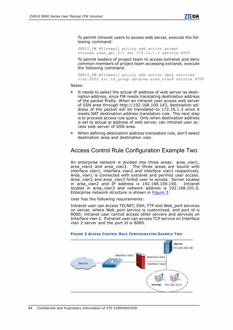
ZXR10 8900 Series User Manual (FW Volume)
To permit intranet users to access web server, execute the fol-lowing command:
ZXR10_FW #firewall policy add action acceptsrcarea area_gei_2/1 dst 172.16.1.3 service HTTP
To permit leaders of project team to access extranet and denycommon members of project team accessing extranet, executethe following command:
ZXR10_FW #firewall policy add action deny ssrcvlanvlan.0002 src rd_group dstarea area_vlan4 service HTTP
Notes:
� It needs to select the actual IP address of web server as desti-nation address, since FW needs translating destination addressof the packet firstly. When an intranet user access web serverof SSN area through http://192.168.100.143, destination ad-dress of the packet will be translated to 172.16.1.3 since itmeets NAT destination address translation rule. The next stepis to proceed access rule query. Only when destination addressis set to actual ip address of web server, can intranet user ac-cess web server of SSN area.
� When defining destination address translation rule, don’t selectdestination area and destination vlan.
Access Control Rule Configuration Example Two
An enterprise network is divided into three areas: area_vlan1,area_vlan2 and area_vlan3. The three areas are bound withinterface vlan1, interface vlan2 and interface vlan3 respectively.Area_vlan1 is connected with extranet and permits user access.Area_vlan2 and area_vlan3 forbid user to access. Server locatesin area_vlan2 and IP address is 192.168.100.140. Intranetlocates in area_vlan3 and network address is 192.168.101.0.Enterprise network structure is shown in Figure 3.
User has the following requirements:
Intranet user can access TELNET, SSH, FTP and Web_port serviceson server, where Web_port service is customized, and port id is8080; intranet user cannot access other servers and services onInterface vlan 2. Extranet user can access TCP service on Interfacevlan 2 server and the port id is 8080.
FIGURE 3 ACCESS CONTROL RULE CONFIGURATION EXAMPLE TWO
84 Confidential and Proprietary Information of ZTE CORPORATION
Chapter 5 Packet Filtering and Access Control Rule Configuration
Configuration Points:
� Defining area and address resources
� Defining service resource
� Defining service group resource
1. Defining area resource: To join gei_2/1, gei_2/2 and gei_2/3to vlan1, vlan2 and vlan3 respectively in access mode, executethe following commands:
ZXR10_FW #define area add name area_vlan1 accesson attribute gei_2/1 ZXR10_FW #define area add name area_vlan2access on attribute gei_2/2 ZXR10_FW #define area add namearea_vlan3 access on attribute gei_2/3
2. Defining host and subnet address resources: To define hostaddress resource "192.168.100.140" and subnet addresssource "intranet resource" inner_web, execute the followingcommands:
ZXR10_FW #define host add name 192.168.100.140ipaddr 192.168.100.140 ZXR10_FW #define subnet add nameinner_web ipaddr 192.168.101.0 mask 255.255.255.0
3. Defining customized service with service name to be Web_portand port id to be 8080, execute the following command:
ZXR10_FW #define service add name Web_portprotocol tcp port 8080
4. Setting service group resource: To name service group toinner_web_srv (intranet access service) and include servicesWeb_port, FTP, Telnet and SSH into this group, execute thefollowing command:
ZXR10_FW #difine group_service add nameinner_web_srv member Web_port,FTP,TELNET,SSH
5. Setting access control rule:
Permit subnet object (intranet) inner_web (192.168.101.0/24)in area_vlan3 to access Web_port, FTP, TELNET and SSH ser-vices (bound with customized service group inner_web_srv)on server of area_vlan2 with server IP address to be192.168.100.140.
ZXR10_FW #firewall policy add action acceptsrcarea area_vlan3 dstarea area_vlan2 src inner_web dst192.168.100.140 service inner_web_srv enable yes
Setting service access control rule to only permit extranetuser (area_vlan1) to access services on port 8080 of server192.168.100.140.
ZXR10_FW #firewall policy add action acceptsrcarea area_vlan1 dstarea area_vlan2 dst 192.168.100.140service Web_port enable yes
Notes:
To permit only partial services to be accessed and deny others,set the default access privilege of destination area to "deny". Sys-tem will match default access privilege of area automatically aftermatching access control rule.
Confidential and Proprietary Information of ZTE CORPORATION 85
ZXR10 8900 Series User Manual (FW Volume)
Configuring IDS InteractionIDS Interaction Overview
It is hard for one security system to integrate all security technolo-gies. It is convenient for management and maintenance to includeIDS, anti-virus, content auditing and other functions into FW andit can also degrade performance of FW, so it is inappropriate forFW which acts as GW to integrate all security technologies. Firstly,IDS needs to update attack pattern database periodically. How-ever it is obviously inappropriate to upgrade critical devices, suchas FW. Secondly, if FW contains too many additional functions, itsrunning speed will be slower, which brings bottleneck for commu-nication between intranet and extranet.
Taking convenience and maintainability of user operation and se-curity system construction into account, FW designs core platformin security system and provides sound assistant system for IDS,anti-virus and other security products to interact with products ofother main IDS and anti-virus manufacturers.
Configuring IDS Interaction
This topic describes how to configure IDS interaction.
1. Adding one IDS interaction rule.
Command Function
ZXR10_FW.pf #idsserver add ip<ipaddress> key <string>
This adds one IDSinteraction rule.
Parameter Description:
Parameter Description
add This adds one IDS interaction rule.
ip This sets IP address for interacted IDS.
<ipaddress> This is IP address string, in format of A.B.C.D.
key This sets shared key with IDS device.
<string> This is one string.
Command Illustration:
� Shared key of FW and interacted IDS device is set manually.If the key of interacted IDS device is generated automat-ically by system , user needs to give the configuration onWEBUI interface. For details, please refer to Logging intoFW through Browser.
86 Confidential and Proprietary Information of ZTE CORPORATION
Chapter 5 Packet Filtering and Access Control Rule Configuration
� To realize interaction between FW and IDS device, it needsto enable IDS servie in corresponding area. For details,please refer to section Setting Open Services.
2. Modifying one IDS interaction rule.
Command Function
ZXR10_FW.pf #idsserver modifyid<number><[ip <ipaddress>][key<string>]>
This modifies one IDSinteraction rule.
Parameter Description:
Parameter Description
modify This modifies one IDS interaction rule.
id This modifies ID for the rule to be modified.
<number> This is one number.
ip It is an option, modifying IP address of IDSinteraction device.
<ipaddress> This is a string, in format of A.B.C.D.
key This modifies shared key of FW and IDS device.
<string> This is one string.
3. Deleting one IDS interaction rule.
Command Function
ZXR10_FW.pf #idsserver delete id<number>
This deletes one IDSinteraction rule.
4. Clearing all IDS interaction servers.
Command Function
ZXR10_FW.pf #idsserver clean This clears all IDSinteraction servers.
5. Showing all IDS interaction rules.
Command Function
ZXR10_FW.pf #idsserver show This shows all IDSinteraction rules.
Confidential and Proprietary Information of ZTE CORPORATION 87

ZXR10 8900 Series User Manual (FW Volume)
This page is intentionally blank.
88 Confidential and Proprietary Information of ZTE CORPORATION
C h a p t e r 6
NAT Configuration
Table of Contents:NAT Overview ...................................................................89Configuring NAT ................................................................90NAT Configuration Example.................................................96
NAT OverviewRapid development of Internet speeds lack of IP addresses. Toalleviate this problem, RFC1631 and related RFC define NetworkAddress Translation (NAT), which is used widely. NAT is to map anIP address from one address domain to another address domain.One of this typical application is to map private IP address definedin RFC1918 to available public IP address in Internet.
RFC 1918 gives the following definitions to private IP address:
Internet Assigned Numbers Authority (IANA) reserves three IP ad-dresses for private network.
10.0.0.0 - 10.255.255.255 (Class A address segment)
172.16.0.0 - 172.31.255.255Class B address segment)
192.168.0.0 - 192.168.255.255 (Class C address segment)
When one user of private IP address needs to access public net-work or one user in public network needs to access one serverwith private IP address, administrator needs to set correspondingaddress translation rule.
AddressTranslationAdvantages
With network address translation, enterprises can use quite a fewInternet public IP addresses to access Internet, which relieves lackof IPv4 addresses and meanwhile provides certain security. NAThas the following advantages:
� Guarantee that intra-users of enterprises using private IP ad-dresses can access Internet normally;
� Protect intranet, hide intranet topology and actual IP, and re-duce direct attacks.
� Protect internal server that provides service externally and pro-vide the function of load balancing.
AddressTranslation Rule
FW card can configure NAT rules flexibly according to user net-work planning and function demands. When user defines addresstranslation rules on FW card, firstly he needs to define source anddestination of this rule, that is source address range and destina-
Confidential and Proprietary Information of ZTE CORPORATION 89
ZXR10 8900 Series User Manual (FW Volume)
tion address range of packet of applicable to address translationrule, then define corresponding services, and the last one is trans-lation control mode. FW card provides the following translationcontrol modes:
� SNAT: Users with private addresses can access public network.
� DNAT: Users in public network can access intranet server withprivate address.
� NoNAT: It can be used to define special cases of SNAT, DNAT,bi-directional NAT rules. In this case, it shall be placed in thefront of NAT rule list.
All address translation rules defined by FW card are stored in ruletable in certain sequence. When one packet passes through FWcard, FW card will retrieve address translation rule table accordingto sequence of address translation rules and match them with thepacket one by one. Once the packet is found to match one addresstranslation rule, FW card will stop retrieving and process the packetaccording to defined rule.
Configuring NATThis topic describes configuration commands and configuration ex-amples of NAT.
Commands in this module are used for address translation policy-related configurations.
To access this command module, execute the following command:
ZXR10_FW # nat
To exit from this command module, execute the following com-mand:
ZXR10_FW # end
1. Adding NAT policy.
Command Function
ZXR10_FW.nat#policy add [srcarea<srcarea_nam>][dstarea <dstarea_nam>][srcvlan <srcvlan_no>][dstvlan<dstvlan_no>][orig_src <src_addr1>][orig_dst <dst_addr1>][orig_sport<sport_id>][orig_service <ser_id>][trans_src < src_addr2>][trans_dst<dst_addr2>][trans_service<ser_obj>][pat <yes|no>][enable<yes|no>][before <number2>]
This adds NAT policy.
Parameter Description:
Parameter Description
add This adds NAT policy.
srcarea This sets source area.
90 Confidential and Proprietary Information of ZTE CORPORATION
Chapter 6 NAT Configuration
Parameter Description
<srcarea_nam> This is one string and source area resourcename is input here.Tips:This parameter value must be predefinedarea name. One ore more area namescan be input here. As for multiple areanames, space is used between each twoarea names and all addresses are quotedwith single quotes, such as ’area1 area2’
dstarea This sets destination area.
<dstarea_nam> This is one string and destination arearesource name is input here.Tips:
a) This parameter value must be predefined area name. One ore more areanames can be input here. As for multiple area names, space is used between each two area names and all areanames are quoted with single quotes,such as ’area1 area2’.
b) When adding destination addresstranslation policy, this parametermustn’t be set.
srcvlan This sets source VLAN.
<srcvlan_no> This is one string and source VLAN nameis input here.Tips:This parameter value must be predefinedVLAN name. One ore more VLAN namescan be input here. As for multiple VLANnames, space is used between each twoVLAN names and all VLAN names arequoted with single quotes, such as ’1 2’.
dstvlan This sets destination VLAN.
<dstvlan_no> This is one string and destination VLANname is input here.Tips:
a) This parameter value must be predefined VLAN name. One ore more VLANnames can be input here. As for multiple VLAN names, space is used between each two VLAN names and all VLANnames are quoted with single quotes,such as ’1 2’.
b) When adding destination addresstranslation policy, this parametermustn’t be set.
orig_src This sets source object of original packet.
Confidential and Proprietary Information of ZTE CORPORATION 91
ZXR10 8900 Series User Manual (FW Volume)
Parameter Description
<src_addr1> This is one string and source object nameof original packet is input here.Tips:
a) This parameter must be one predefined address object name.
b) Multiple address objects can beinput at the same time, in format of’test1 test2’. As for multiple addressobjects, space is used between eachtwo and all address object names arequoted with single quotes.
orig_dst This sets destination object of originalpacket.
<dst_addr1> This is one string and source object nameof original packet is input here.Tips:
a) This parameter must be one predefined address object name.
b) Multiple address objects can beinput at the same time, in format of’test1 test2’. As for multiple addressobjects, space is used between eachtwo and all address object names arequoted with single quotes.
orig_sport This sets source port of original packet.
<sport_id> This is one string and source port name oforiginal packet is input here.Tips:
a) This parameter must be one predefined port name.
b) Multiple port objects can be inputat the same time, in format of ’server1server2’. As for multiple port objects,space is used between each two andall port names are quoted with singlequotes.
orig_service This sets service resource of originalpacket.
<ser_id> This is one string and service resourcename of original packet is input here.Tips:
a) This parameter must be one predefined service resource.
b) Multiple service resources can beinput at the same time, in format of ’server1 server2’. As for multiple serviceresources, space is used between eachtwo and all address object names arequoted with single quotes.
trans_src This sets source object after translation.
92 Confidential and Proprietary Information of ZTE CORPORATION
Chapter 6 NAT Configuration
Parameter Description
<src_addr2> This is one string and source object nameafter translation is input here.Tips:
a) This parameter must be one predefined address object name or attributename.
b) Only one object can be input here.
c) This parameter is necessary whenadding source address translation policy.
trans_dst This sets destination object aftertranslation.
<dst_addr2> This is one string and destination objectname after translation is input here.Tips:
a) This parameter must be one predefined address object name or attributename.
b) Only one object can be input here.
c) This parameter is necessary whenadding destination address translationpolicy.
trans_service This sets service resource after translation.
<ser_obj> This is the number and service resourcename after translation is input here.Tips:This parameter must be one namepredefined in define module.
pat This sets source port translation switch.
yes|no YES means conducting port addresstranslation to source port and no meansnot conducting port address translation tosource port.Tips:Yes is the default value.
enable This sets address translation policy switch.
yes|no Yes means enabling this address translationpolicy and no means forbidding this addresstranslation policy temporarily.Tips:Yes is the default value.
Confidential and Proprietary Information of ZTE CORPORATION 93
ZXR10 8900 Series User Manual (FW Volume)
Parameter Description
before This places this address translation policybefore one policy.
<number> This is one number, which shall be ID ofthe next address translation policy afterinputting this address translation policy.Tips:
a) This parameter must be id of anadded address translation policy.
b) To view id of system default serviceresource, execute the following command:
define service show default
Command Illustration:
When defining destination address translation policy, don’tspecify destination area and destination vlan.
System also translates source port address by default whentranslating source address.
Attribute resource with no interface binding cannot be used asaddress after translation of address translation policy.
2. Modifying NAT policy.
Command Function
ZXR10_FW.nat#policy modify id <number1>[srcarea <srcarea_nam>][dstarea<dstarea_nam>][srcvlan <srcvlan_no>][dstvlan <dstvlan_no>][orig_src<src_addr1>][orig_dst <dst_addr1>][orig_sport <sport_id>][orig_service<ser_id>][trans_src < src_addr2>][trans_dst <dst_addr2>][trans_service<ser_obj>][pat <yes|no>][enable<yes|no>]
Modifying NAT policy.
Parameter Description:
Parameter Description
modify This modifies NAT policy.
id This sets ID of policy to be modified.
<number> This is one number, which is the ID ofpolicy to be modified.
3. Deleting one NAT policy.
Command Function
ZXR10_FW.nat#policy delete id<number1>
This deletes one NATpolicy.
Parameter Description:
94 Confidential and Proprietary Information of ZTE CORPORATION
Chapter 6 NAT Configuration
Parameter Description
<number1> This is one number, which is the ID of NATpolicy to be deleted.
4. Showing NAT policy.
Command Function
ZXR10_FW.nat#policy show This shows NAT policy.
5. Clearing NAT policy.
Command Function
ZXR10_FW.nat#policy clean This clears NAT policy.
6. Moving NAT policy.
Command Function
ZXR10_FW.nat#policy move<number1>[<before <number2>|after<number3>]
This moves NATpolicy. NAT policyconforms to sequentialmatching principle. Bymoving NAT policy,matching priority ofpolicy can be changed.
Parameter Description:
Parameter Description
<number1> This is one number, which is the ID of NATpolicy to be moved.
<number2> This is one number, which is the ID ofpolicy.Tips:Values of parameters before and aftercannot be set at the same time.
<numbe3> This is one number, which is the ID ofpolicy.Tips:Values of parameters before and aftercannot be set at the same time.
Confidential and Proprietary Information of ZTE CORPORATION 95
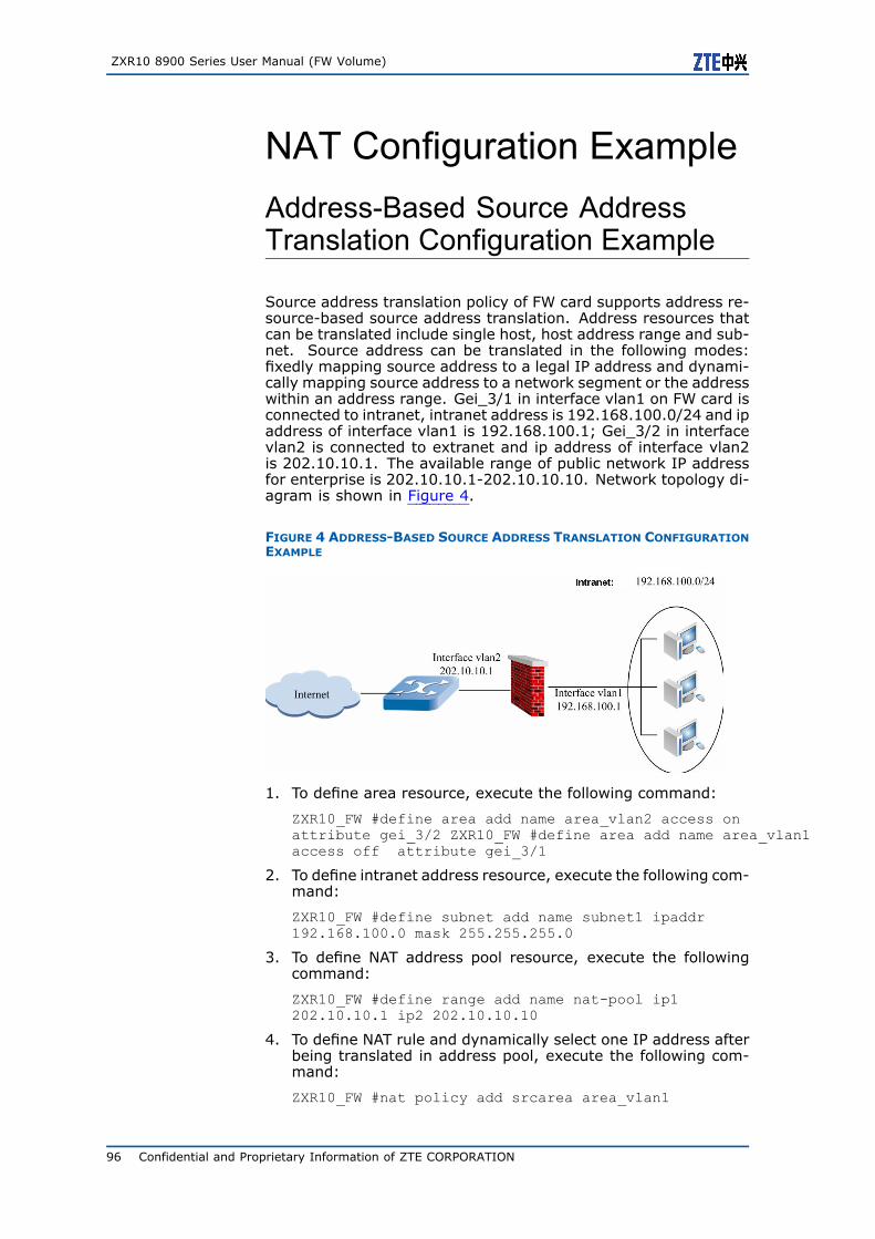
ZXR10 8900 Series User Manual (FW Volume)
NAT Configuration ExampleAddress-Based Source AddressTranslation Configuration Example
Source address translation policy of FW card supports address re-source-based source address translation. Address resources thatcan be translated include single host, host address range and sub-net. Source address can be translated in the following modes:fixedly mapping source address to a legal IP address and dynami-cally mapping source address to a network segment or the addresswithin an address range. Gei_3/1 in interface vlan1 on FW card isconnected to intranet, intranet address is 192.168.100.0/24 and ipaddress of interface vlan1 is 192.168.100.1; Gei_3/2 in interfacevlan2 is connected to extranet and ip address of interface vlan2is 202.10.10.1. The available range of public network IP addressfor enterprise is 202.10.10.1-202.10.10.10. Network topology di-agram is shown in Figure 4.
FIGURE 4 ADDRESS-BASED SOURCE ADDRESS TRANSLATION CONFIGURATIONEXAMPLE
1. To define area resource, execute the following command:
ZXR10_FW #define area add name area_vlan2 access onattribute gei_3/2 ZXR10_FW #define area add name area_vlan1access off attribute gei_3/1
2. To define intranet address resource, execute the following com-mand:
ZXR10_FW #define subnet add name subnet1 ipaddr192.168.100.0 mask 255.255.255.0
3. To define NAT address pool resource, execute the followingcommand:
ZXR10_FW #define range add name nat-pool ip1202.10.10.1 ip2 202.10.10.10
4. To define NAT rule and dynamically select one IP address afterbeing translated in address pool, execute the following com-mand:
ZXR10_FW #nat policy add srcarea area_vlan1
96 Confidential and Proprietary Information of ZTE CORPORATION
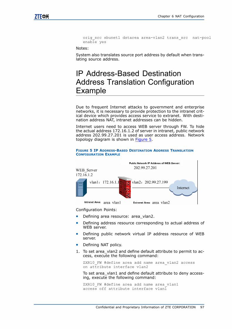
Chapter 6 NAT Configuration
orig_src sbunet1 dstarea area-vlan2 trans_src nat-poolenable yes
Notes:
System also translates source port address by default when trans-lating source address.
IP Address-Based DestinationAddress Translation ConfigurationExample
Due to frequent Internet attacks to government and enterprisenetworks, it is necessary to provide protection to the intranet crit-ical device which provides access service to extranet. With desti-nation address NAT, intranet addresses can be hidden.
Internet users need to access WEB server through FW. To hidethe actual address 172.16.1.2 of server in intranet, public networkaddress 202.99.27.201 is used as user access address. Networktopology diagram is shown in Figure 5.
FIGURE 5 IP ADDRESS-BASED DESTINATION ADDRESS TRANSLATIONCONFIGURATION EXAMPLE
Configuration Points:
� Defining area resource: area_vlan2.
� Defining address resource corresponding to actual address ofWEB server.
� Defining public network virtual IP address resource of WEBserver.
� Defining NAT policy.
1. To set area_vlan2 and define default attribute to permit to ac-cess, execute the following command:
ZXR10_FW #define area add name area_vlan2 accesson attribute interface vlan2
To set area_vlan1 and define default attribute to deny access-ing, execute the following command:
ZXR10_FW #define area add name area_vlan1access off attribute interface vlan1
Confidential and Proprietary Information of ZTE CORPORATION 97
ZXR10 8900 Series User Manual (FW Volume)
2. To specify actual address of WEB server, execute the followingcommand:
ZXR10_FW #define host add nameWEB_server ipaddr 172.16.1.2
3. To specify public network address of WEB server, execute thefollowing command:
ZXR10_FW #define host add name MAP_IP ipaddr202.99.27.201
4. To set NAT rule, execute the following command:
ZXR10_FW #nat policy add srcarea area_vlan2 orig_dstMAP_IP orig_service http trans_dst WEB_server
Notes:
� When defining destination address translation policy, don’tspecify destination area and destination vlan.
� If web server uses customized port id rather than standard port80 to provide web service, the actual applied server port shallbe filled in "destination port is translated to" when definingaddress translation policy. For detailed configuration method,please refer to "Port-Based Destination NAT" configuration ex-ample.
Port-Based Destination AddressTranslation Configuration Example
Basic requirement: With destination address NAT, intranet ad-dresses can be hidden. However, sometimes server open appli-cation port is different from the port used for user access (defaultport in usual cases). In this case, NAT is necessary.
Public Internet user accesses web server through public address202.99.27.199:80. Actual address of web server is 172.16.1.2and the port providing HTTP service is 8080. The network topologydiagram is as shown in Figure 6.
FIGURE 6 PORT-BASED DESTINATION ADDRESS TRANSLATIONCONFIGURATION EXAMPLE
Configuration Points:
� Defining area resource.
98 Confidential and Proprietary Information of ZTE CORPORATION
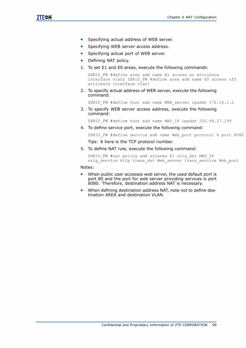
Chapter 6 NAT Configuration
� Specifying actual address of WEB server.
� Specifying WEB server access address.
� Specifying actual port of WEB server.
� Defining NAT policy.
1. To set E1 and E0 areas, execute the following commands:
ZXR10_FW #define area add name E1 access on attributeinterface vlan2 ZXR10_FW #define area add name E0 access offattribute interface vlan1
2. To specify actual address of WEB server, execute the followingcommand:
ZXR10_FW #define host add name WEB_server ipaddr 172.16.1.2
3. To specify WEB server access address, execute the followingcommand:
ZXR10_FW #define host add name MAP_IP ipaddr 202.99.27.199
4. To define service port, execute the following command:
ZXR10_FW #define service add name Web_port protocol 6 port 8080
Tips: 6 here is the TCP protocol number.
5. To define NAT rule, execute the following command:
ZXR10_FW #nat policy add srcarea E1 orig_dst MAP_IPorig_service http trans_dst Web_server trans_service Web_port
Notes:
� When public user accesses web server, the used default port isport 80 and the port for web server providing services is port8080. Therefore, destination address NAT is necessary.
� When defining destination address NAT, note not to define des-tination AREA and destination VLAN.
Confidential and Proprietary Information of ZTE CORPORATION 99

ZXR10 8900 Series User Manual (FW Volume)
This page is intentionally blank.
100 Confidential and Proprietary Information of ZTE CORPORATION
C h a p t e r 7
Protocol FilteringConfiguration
Table of Contents:Protocol Filtering Overview ............................................... 101Configuring Application Port Binding................................... 101Configuring SIP Service.................................................... 104
Protocol Filtering OverviewFW card can provide control over application layer with finer gran-ularity through content filtering. At present, FW card permits userto bind application layer protocol with port.
Configuring Application PortBindingApplication Port Binding Overview
Application port binding on FW card is used to bind applicationlayer protocol and port. When FW card performs deep contentdetection to application layer protocol, it will check these packetsand perform corresponding processing.
System defines parting bindings between application layer proto-cols and standard ports by default. In case some application layerprotocols use non-standard ports or sub-connection (such as FTP)is contained, user must bind these ports and application layer pro-tocols, or FW card will fail to detect and process these packets.For example, there is one FTP server in intranet SSN area andnon-standard port 2200 is used to provide FTP service for intranetusers. In case application port binding is unavailable, FW will notprocess packets of this connection. Customize application protocolport binding policy.
System has the following default standard ports:
Confidential and Proprietary Information of ZTE CORPORATION 101
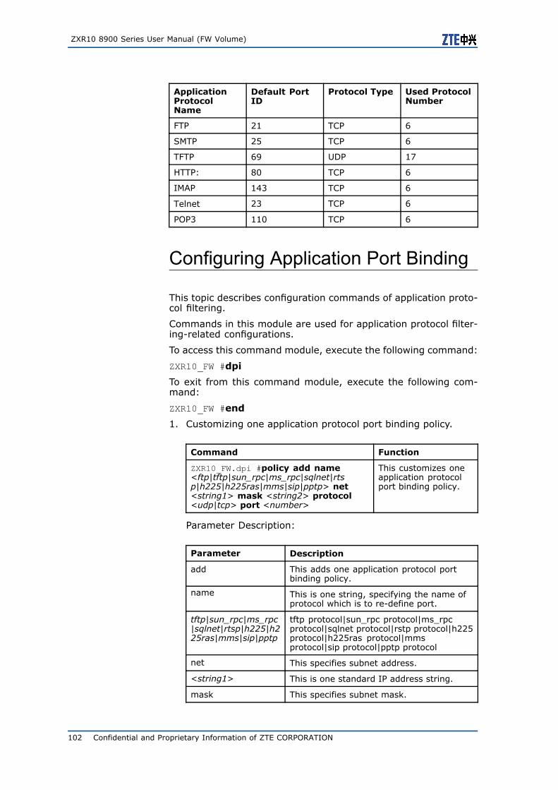
ZXR10 8900 Series User Manual (FW Volume)
ApplicationProtocolName
Default PortID
Protocol Type Used ProtocolNumber
FTP 21 TCP 6
SMTP 25 TCP 6
TFTP 69 UDP 17
HTTP: 80 TCP 6
IMAP 143 TCP 6
Telnet 23 TCP 6
POP3 110 TCP 6
Configuring Application Port Binding
This topic describes configuration commands of application proto-col filtering.
Commands in this module are used for application protocol filter-ing-related configurations.
To access this command module, execute the following command:
ZXR10_FW #dpi
To exit from this command module, execute the following com-mand:
ZXR10_FW #end
1. Customizing one application protocol port binding policy.
Command Function
ZXR10_FW.dpi #policy add name<ftp|tftp|sun_rpc|ms_rpc|sqlnet|rtsp|h225|h225ras|mms|sip|pptp> net<string1> mask <string2> protocol<udp|tcp> port <number>
This customizes oneapplication protocolport binding policy.
Parameter Description:
Parameter Description
add This adds one application protocol portbinding policy.
name This is one string, specifying the name ofprotocol which is to re-define port.
tftp|sun_rpc|ms_rpc|sqlnet|rtsp|h225|h225ras|mms|sip|pptp
tftp protocol|sun_rpc protocol|ms_rpcprotocol|sqlnet protocol|rstp protocol|h225protocol|h225ras protocol|mmsprotocol|sip protocol|pptp protocol
net This specifies subnet address.
<string1> This is one standard IP address string.
mask This specifies subnet mask.
102 Confidential and Proprietary Information of ZTE CORPORATION
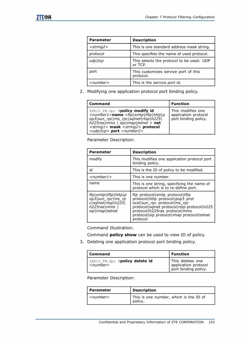
Chapter 7 Protocol Filtering Configuration
Parameter Description
<string2> This is one standard address mask string.
protocol This specifies the name of used protocol.
udp|tcp This selects the protocol to be used: UDPor TCP.
port This customizes service port of thisprotocol.
<number> This is the service port id.
2. Modifying one application protocol port binding policy.
Command Function
ZXR10_FW.dpi #policy modify id<number1>name <ftp|smtp|tftp|http|pop3|sun_rpc|ms_rpc|sqlnet|rtsp|h225|h225ras|mms | sip|imap|telnet > net<string1> mask <string2> protocol<udp|tcp> port <number2>
This modifies oneapplication protocolport binding policy.
Parameter Description:
Parameter Description
modify This modifies one application protocol portbinding policy.
id This is the ID of policy to be modified.
<number1> This is one number.
name This is one string, specifying the name ofprotocol which is to re-define port.
ftp|smtp|tftp|http|pop3|sun_rpc|ms_rpc|sqlnet|rtsp|h225|h225ras|mms |sip|imap|telnet
ftp protocol|smtp protocol|tftpprotocol|http protocol|pop3 protocol|sun_rpc protocol|ms_rpcprotocol|sqlnet protocol|rstp protocol|h225protocol|h225ras protocol|mmsprotocol|sip protocol|imap protocol|telnetprotocol
Command Illustration:
Command policy show can be used to view ID of policy.
3. Deleting one application protocol port binding policy.
Command Function
ZXR10_FW.dpi #policy delete id<number>
This deletes oneapplication protocolport binding policy.
Parameter Description:
Parameter Description
<number> This is one number, which is the ID ofpolicy.
Confidential and Proprietary Information of ZTE CORPORATION 103
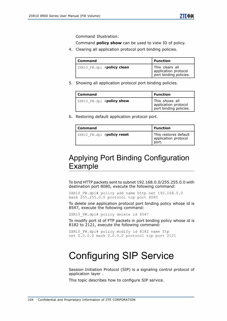
ZXR10 8900 Series User Manual (FW Volume)
Command Illustration:
Command policy show can be used to view ID of policy.
4. Clearing all application protocol port binding policies.
Command Function
ZXR10_FW.dpi #policy clean This clears allapplication protocolport binding policies.
5. Showing all application protocol port binding policies.
Command Function
ZXR10_FW.dpi #policy show This shows allapplication protocolport binding policies.
6. Restoring default application protocol port.
Command Function
ZXR10_FW.dpi #policy reset This restores defaultapplication protocolport.
Applying Port Binding ConfigurationExample
To bind HTTP packets sent to subnet 192.168.0.0/255.255.0.0 withdestination port 8080, execute the following command:
ZXR10_FW.dpi# policy add name http net 192.168.0.0mask 255.255.0.0 protocol tcp port 8080
To delete one application protocol port binding policy whose id is8547, execute the following command:
ZXR10_FW.dpi# policy delete id 8547
To modify port id of FTP packets in port binding policy whose id is8182 to 2121, execute the following command:
ZXR10_FW.dpi# policy modify id 8182 name ftpnet 0.0.0.0 mask 0.0.0.0 protocol tcp port 2121
Configuring SIP ServiceSession Initiation Protocol (SIP) is a signaling control protocol ofapplication layer .
This topic describes how to configure SIP service.
104 Confidential and Proprietary Information of ZTE CORPORATION
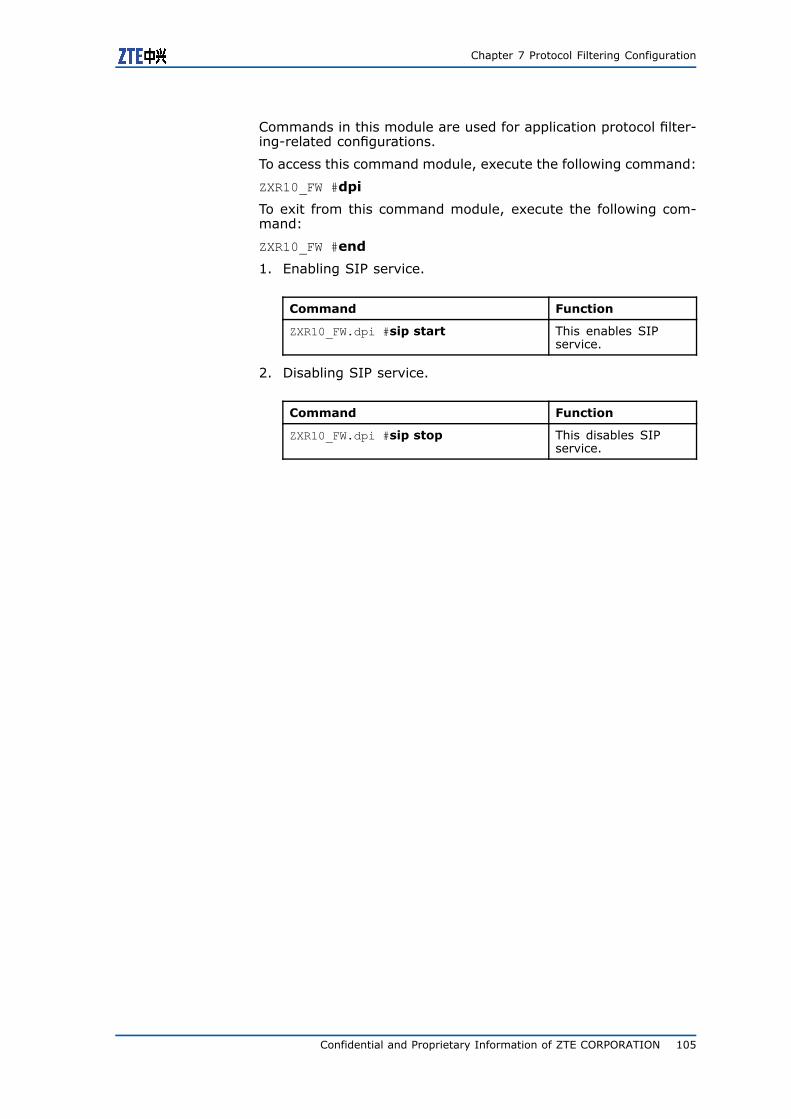
Chapter 7 Protocol Filtering Configuration
Commands in this module are used for application protocol filter-ing-related configurations.
To access this command module, execute the following command:
ZXR10_FW #dpi
To exit from this command module, execute the following com-mand:
ZXR10_FW #end
1. Enabling SIP service.
Command Function
ZXR10_FW.dpi #sip start This enables SIPservice.
2. Disabling SIP service.
Command Function
ZXR10_FW.dpi #sip stop This disables SIPservice.
Confidential and Proprietary Information of ZTE CORPORATION 105

ZXR10 8900 Series User Manual (FW Volume)
This page is intentionally blank.
106 Confidential and Proprietary Information of ZTE CORPORATION
C h a p t e r 8
Intrusion PreventionConfiguration
Table of Contents:Intrusion Prevention Overview........................................... 107Configuring Intrusion Detection Rule .................................. 107
Intrusion PreventionOverviewFW card has a built-in IDS module, used to detect and defendcommon attacks and scanning. Meanwhile, FW card can realizeinteraction with intrusion detection system of other manufacturersand provides comprehensive and efficient security protection touser intranet.
This chapter has the following content:
� Host intrusion prevention. This topic describes how does FWcard provide host intrusion prevention function to all hosts.
� Anti-DOS. This topic describes how does FW card detect anddefend common attacks.
Configuring IntrusionDetection RuleThis topic describes commands of configuring intrusion detectionrule.
To access this command module, execute the following command:
ZXR10_FW #ips
To exit from this command module, execute the following com-mand:
ZXR10_FW #end
Confidential and Proprietary Information of ZTE CORPORATION 107
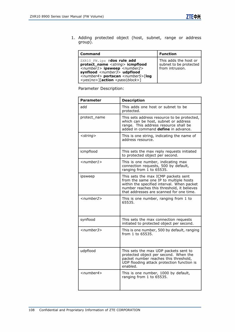
ZXR10 8900 Series User Manual (FW Volume)
1. Adding protected object (host, subnet, range or addressgroup).
Command Function
ZXR10_FW.ips #dos rule addprotect_name <string> icmpflood<number1> ipsweep <number2>synflood <number3> udpflood<number4> portscan <number5>[log<yes|no>][action <pass|block>]
This adds the host orsubnet to be protectedfrom intrusion.
Parameter Description:
Parameter Description
add This adds one host or subnet to beprotected.
protect_name This sets address resource to be protected,which can be host, subnet or addressrange. This address resource shall beadded in command define in advance.
<string> This is one string, indicating the name ofaddress resource.
icmpflood This sets the max reply requests initiatedto protected object per second.
<number1> This is one number, indicating maxconnection requests, 500 by default,ranging from 1 to 65535.
ipsweep This sets the max ICMP packets sentfrom the same one IP to multiple hostswithin the specified interval. When packetnumber reaches this threshold, it believesthat addresses are scanned for one time.
<number2> This is one number, ranging from 1 to65535.
synflood This sets the max connection requestsinitiated to protected object per second.
<number3> This is one number, 500 by default, rangingfrom 1 to 65535.
udpflood This sets the max UDP packets sent toprotected object per second. When thepacket number reaches this threshold,UDP flooding attack protection function isenabled.
<number4> This is one number, 1000 by default,ranging from 1 to 65535.
108 Confidential and Proprietary Information of ZTE CORPORATION
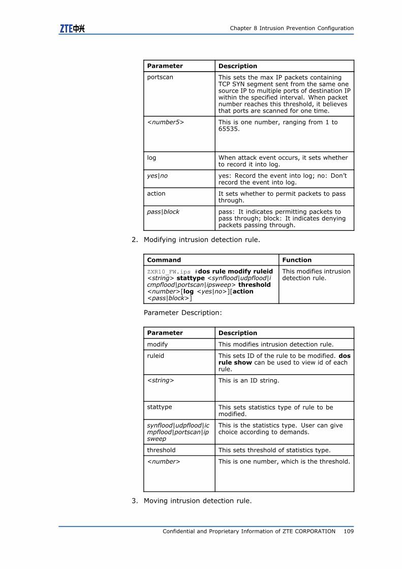
Chapter 8 Intrusion Prevention Configuration
Parameter Description
portscan This sets the max IP packets containingTCP SYN segment sent from the same onesource IP to multiple ports of destination IPwithin the specified interval. When packetnumber reaches this threshold, it believesthat ports are scanned for one time.
<number5> This is one number, ranging from 1 to65535.
log When attack event occurs, it sets whetherto record it into log.
yes|no yes: Record the event into log; no: Don’trecord the event into log.
action It sets whether to permit packets to passthrough.
pass|block pass: It indicates permitting packets topass through; block: It indicates denyingpackets passing through.
2. Modifying intrusion detection rule.
Command Function
ZXR10_FW.ips #dos rule modify ruleid<string> stattype <synflood|udpflood|icmpflood|portscan|ipsweep> threshold<number>[log <yes|no>][action<pass|block>]
This modifies intrusiondetection rule.
Parameter Description:
Parameter Description
modify This modifies intrusion detection rule.
ruleid This sets ID of the rule to be modified. dosrule show can be used to view id of eachrule.
<string> This is an ID string.
stattype This sets statistics type of rule to bemodified.
synflood|udpflood|icmpflood|portscan|ipsweep
This is the statistics type. User can givechoice according to demands.
threshold This sets threshold of statistics type.
<number> This is one number, which is the threshold.
3. Moving intrusion detection rule.
Confidential and Proprietary Information of ZTE CORPORATION 109
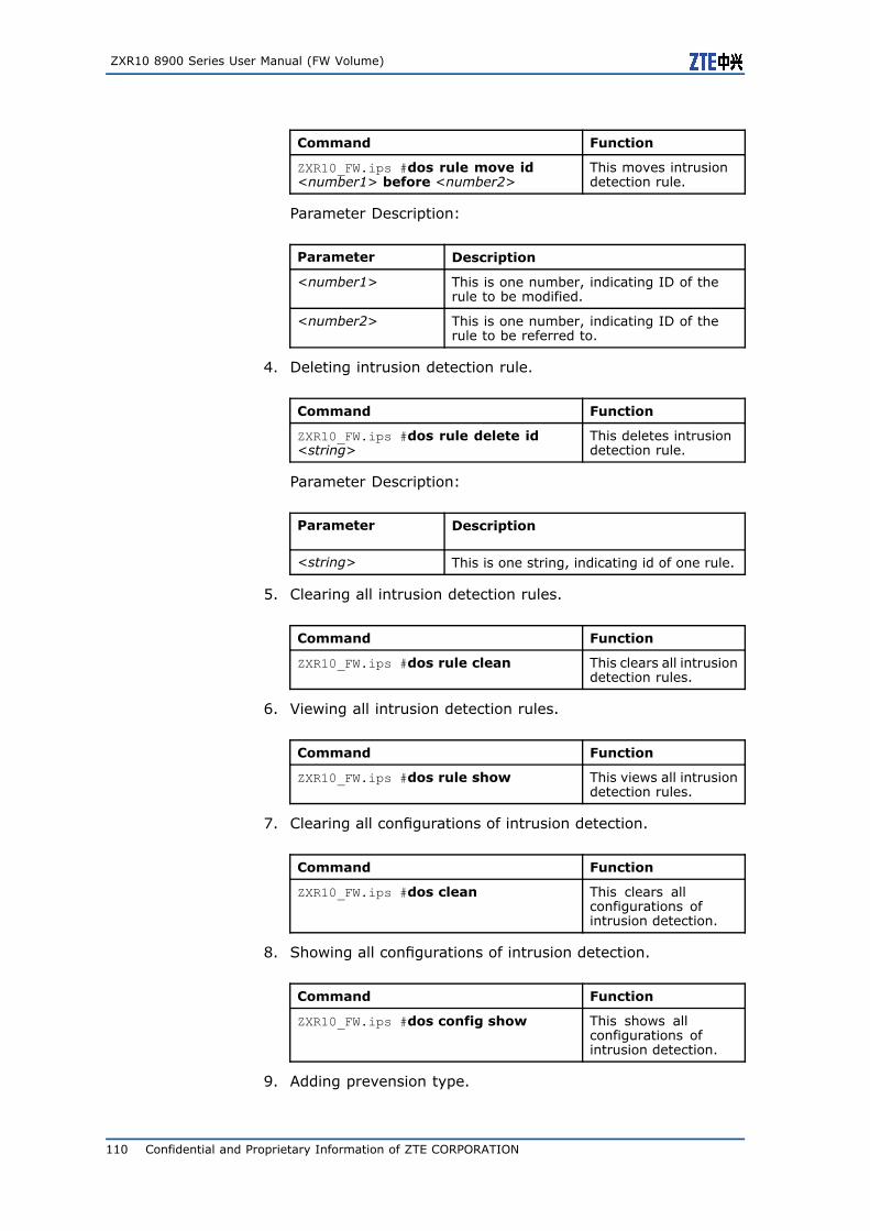
ZXR10 8900 Series User Manual (FW Volume)
Command Function
ZXR10_FW.ips #dos rule move id<number1> before <number2>
This moves intrusiondetection rule.
Parameter Description:
Parameter Description
<number1> This is one number, indicating ID of therule to be modified.
<number2> This is one number, indicating ID of therule to be referred to.
4. Deleting intrusion detection rule.
Command Function
ZXR10_FW.ips #dos rule delete id<string>
This deletes intrusiondetection rule.
Parameter Description:
Parameter Description
<string> This is one string, indicating id of one rule.
5. Clearing all intrusion detection rules.
Command Function
ZXR10_FW.ips #dos rule clean This clears all intrusiondetection rules.
6. Viewing all intrusion detection rules.
Command Function
ZXR10_FW.ips #dos rule show This views all intrusiondetection rules.
7. Clearing all configurations of intrusion detection.
Command Function
ZXR10_FW.ips #dos clean This clears allconfigurations ofintrusion detection.
8. Showing all configurations of intrusion detection.
Command Function
ZXR10_FW.ips #dos config show This shows allconfigurations ofintrusion detection.
9. Adding prevension type.
110 Confidential and Proprietary Information of ZTE CORPORATION
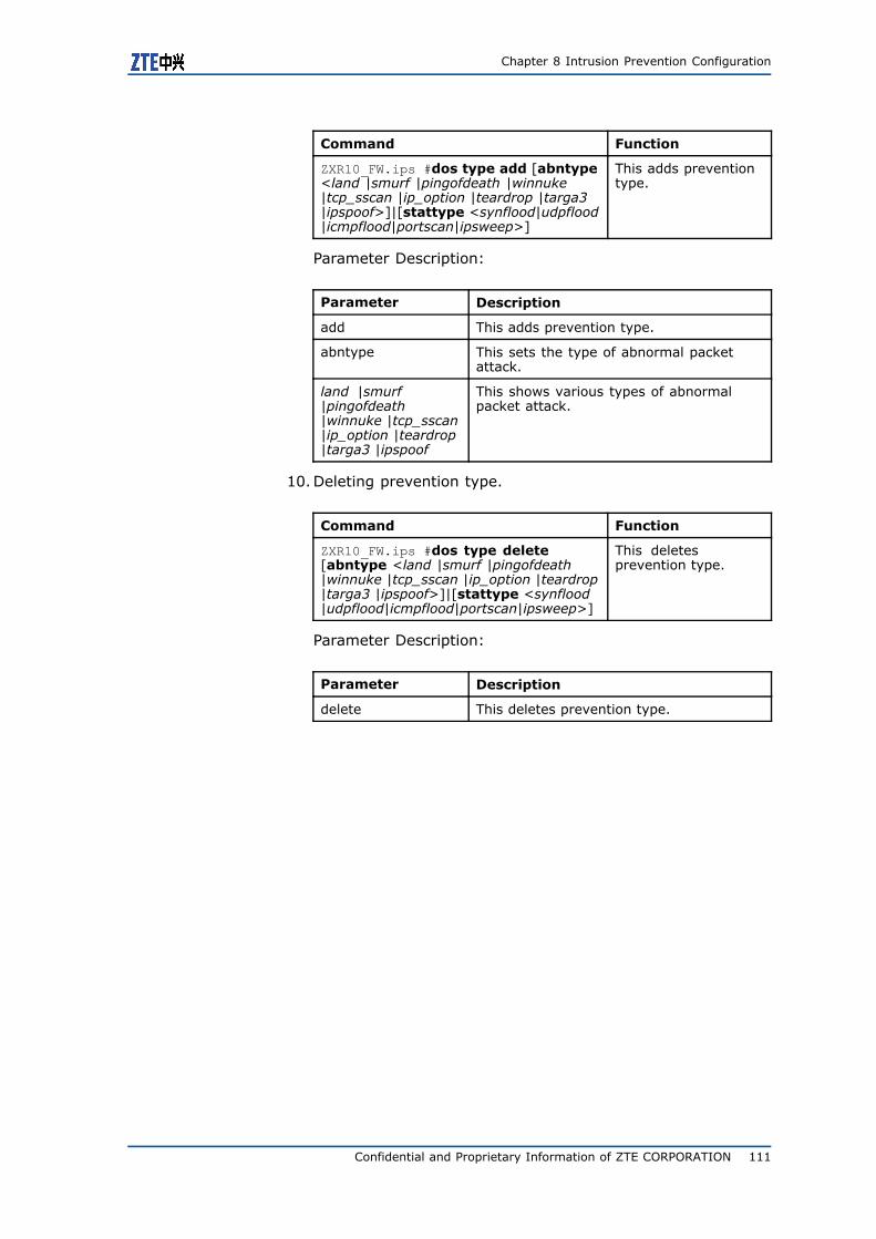
Chapter 8 Intrusion Prevention Configuration
Command Function
ZXR10_FW.ips #dos type add [abntype<land |smurf |pingofdeath |winnuke|tcp_sscan |ip_option |teardrop |targa3|ipspoof>]|[stattype <synflood|udpflood|icmpflood|portscan|ipsweep>]
This adds preventiontype.
Parameter Description:
Parameter Description
add This adds prevention type.
abntype This sets the type of abnormal packetattack.
land |smurf|pingofdeath|winnuke |tcp_sscan|ip_option |teardrop|targa3 |ipspoof
This shows various types of abnormalpacket attack.
10.Deleting prevention type.
Command Function
ZXR10_FW.ips #dos type delete[abntype <land |smurf |pingofdeath|winnuke |tcp_sscan |ip_option |teardrop|targa3 |ipspoof>]|[stattype <synflood|udpflood|icmpflood|portscan|ipsweep>]
This deletesprevention type.
Parameter Description:
Parameter Description
delete This deletes prevention type.
Confidential and Proprietary Information of ZTE CORPORATION 111
ZXR10 8900 Series User Manual (FW Volume)
This page is intentionally blank.
112 Confidential and Proprietary Information of ZTE CORPORATION
C h a p t e r 9
Load BalancingConfiguration
Table of Contents:Load Balancing Overview.................................................. 113Configuring Load Balancing............................................... 113High Availability Configuration Example .............................. 119
Load Balancing OverviewHigh availability means some advanced characteristics of ZXR108900 Series Switch FW, including:
Server load balancing. It mainly describes how to define load bal-ancing server and load balancing group, and how to meet useraccess demands through load balancing.
ZXR10 8900 Series Switch FW can implement load balancing ofuser server according to user demands and flexible load balancingalgorithm so as to guarantee effectiveness of user critical services.ZXR10 8900 Series Switch FW supports session-based load balanc-ing.
There are three ways to realize ZXR10 8900 Series Switch FWserver load balancing function:
1. Defining server
2. Defining load balancing group
3. Defining NAT rule
Configuring Load BalancingConfiguring Load Balancing Server
This topic describes configuration commands and examples of loadbalancing.
Confidential and Proprietary Information of ZTE CORPORATION 113
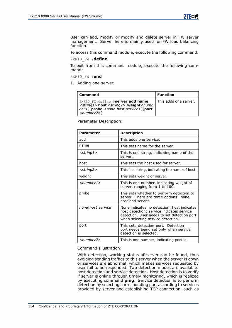
ZXR10 8900 Series User Manual (FW Volume)
User can add, modify or modify and delete server in FW servermanagement. Server here is mainly used for FW load balancingfunction.
To access this command module, execute the following command:
ZXR10_FW #define
To exit from this command module, execute the following com-mand:
ZXR10_FW #end
1. Adding one server.
Command Function
ZXR10_FW.define #server add name<string1> host<string2>[weight<number1>][probe <none|host|service>][port<number2>]
This adds one server.
Parameter Description:
Parameter Description
add This adds one service.
name This sets name for the server.
<string1> This is one string, indicating name of theserver.
host This sets the host used for server.
<string2> This is a string, indicating the name of host.
weight This sets weight of server.
<number1> This is one number, indicating weight ofserver, ranging from 1 to 100.
probe This sets whether to perform detection toserver. There are three options: none,host and service.
none|host|service None indicates no detection; host indicateshost detection; service indicates servicedetection. User needs to set detection portwhen selecting service detection.
port This sets detection port. Detectionport needs being set only when servicedetection is selected.
<number2> This is one number, indicating port id.
Command Illustration:
With detection, working status of server can be found, thusavoiding sending traffics to this server when the server is downor services are abnormal, which makes services requested byuser fail to be responded. Two detection modes are available:host detection and service detection. Host detection is to verifyif server is online through timely monitoring, which is realizedby executing command ping. Service detection is to performdetection by selecting corresponding port according to servicesprovided by server and establishing TCP connection, such as
114 Confidential and Proprietary Information of ZTE CORPORATION
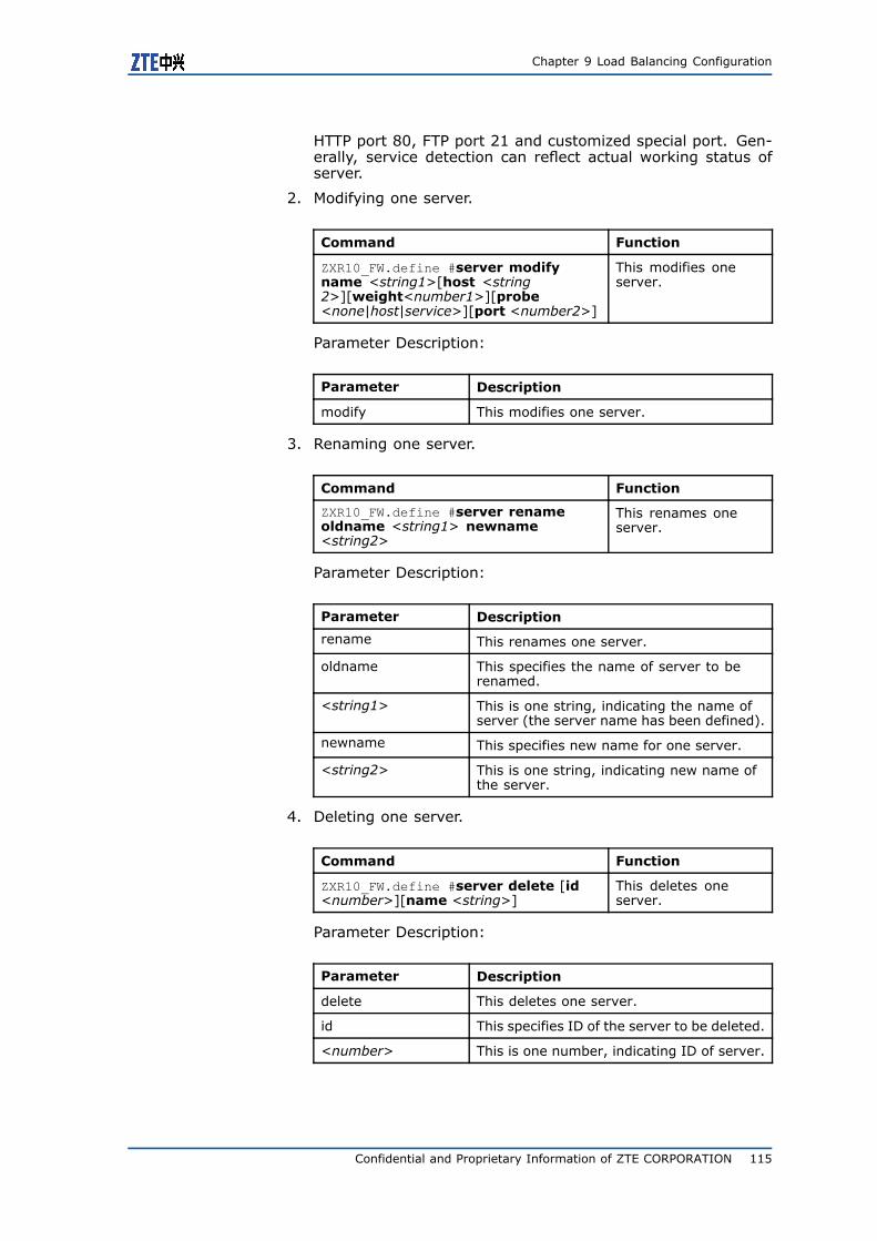
Chapter 9 Load Balancing Configuration
HTTP port 80, FTP port 21 and customized special port. Gen-erally, service detection can reflect actual working status ofserver.
2. Modifying one server.
Command Function
ZXR10_FW.define #server modifyname <string1>[host <string2>][weight<number1>][probe<none|host|service>][port <number2>]
This modifies oneserver.
Parameter Description:
Parameter Description
modify This modifies one server.
3. Renaming one server.
Command Function
ZXR10_FW.define #server renameoldname <string1> newname<string2>
This renames oneserver.
Parameter Description:
Parameter Description
rename This renames one server.
oldname This specifies the name of server to berenamed.
<string1> This is one string, indicating the name ofserver (the server name has been defined).
newname This specifies new name for one server.
<string2> This is one string, indicating new name ofthe server.
4. Deleting one server.
Command Function
ZXR10_FW.define #server delete [id<number>][name <string>]
This deletes oneserver.
Parameter Description:
Parameter Description
delete This deletes one server.
id This specifies ID of the server to be deleted.
<number> This is one number, indicating ID of server.
Confidential and Proprietary Information of ZTE CORPORATION 115
ZXR10 8900 Series User Manual (FW Volume)
Parameter Description
name This specifies the name of server to bedeleted.
<string> This is one string, indicating name of theserver.
Command Illustration:
To delete server, it is available to delete the server accordingto server name, server id or both. However, in case serverid and server name are inconsistent, server name shall apply.When no parameter is given, the server not quoted by policyis deleted.
5. This deletes all servers not quoted by policy.
Command Function
ZXR10_FW.define #server clean This deletes all serversnot quoted by policy.
6. Showing all servers.
Command Function
ZXR10_FW.define #server show This shows all servers.
Configuring Load Balancing Group
This topic describes configuration commands and examples of loadbalancing group.
User can add, modify and delete load balancing group in manage-ment of FW load balancing group.
1. Adding one load balancing group.
Command Function
ZXR10_FW.define #virtual_server addname <string1>[server <string2>][balance<rr|wrr|lc|wlc|sh|dh>][backup<number>]
This adds one loadbalancing group.
Parameter Description:
Parameter Description
add This adds one load balancing group.
name This sets name for load balancing group.
<string1> This is one string, indicating the name ofload balancing group.
server This sets the server contained in loadbalancing group.
116 Confidential and Proprietary Information of ZTE CORPORATION
Chapter 9 Load Balancing Configuration
Parameter Description
<string2> This is one string, indicating the name ofserver. As for multiple server names, spaceis used between each two server namesand all server names are quoted with singlequotes, such as ’server1 server2’.
balance This sets load balancing mode. Six modesare available: rr, wrr, lc, wlc, sh and dh.
rr|wrr|lc|wlc|sh|dh "rr" indicates selecting server in loadbalancing group sequentially; "wrr"indicates selecting load balancing server insequence of weight; "lc" indicates selectingserver according to response time, thefaster the response time, the higher thepriority; "wlc" indicates selecting serveraccording to response time and weight;the shorter the response time and thelarger the weight, the larger the priority;"sh" indicates selecting server with HASHquery according to source address; "dh"indicates selecting server with HASH queryaccording to destination address.
backup This specifies ID of backup load balancinggroup. When all servers in one group stopproviding services, data in servers of loadbalancing group will be backed up to thespecified load balancing group.
<number> This is one number, indicating ID of loadbalancing group.
Command Illustration:
During communication process, if one server is deleted fromthe load balancing group, connections on this server will notbe disconnected and only after re-establishment of connection,can configuration of load balancing group take effect.
If connected server gets disconnected during communication,client will not be connected to another server in load balancinggroup unless re-establishing connection.
When load balancing mode is set to weight balance algorithm,the total number of connections is assigned according to weightvalue. Here weight value is not priority.
"dh" and "sh" algorithms proceed HASH query according to IPaddress. Only when source IP and destination IP are disperse,can connections be allocated to different servers averagely.
Load balancing server can be defined before defining load bal-ancing group. For details, please refer to section ConfiguringHigh Availability.
2. Modifying one load balancing group.
Command Function
ZXR10_FW.define #virtual_servermodify name <string1>[server<string2>][balance<rr|wrr|lc|wlc|sh|dh>][backup <number>]
This modifies one loadbalancing group.
Confidential and Proprietary Information of ZTE CORPORATION 117
ZXR10 8900 Series User Manual (FW Volume)
Parameter Description:
Parameter Description
modify This modifies one load balancing group.
3. Renaming load balancing group.
Command Function
ZXR10_FW.define #virtual_serverrename oldname <string1> newname<string2>
This renames loadbalancing group.
Parameter Description:
Parameter Description
rename This renames load balancing group.
oldname This specifies the name of load balancinggroup to be renamed.
<string1> This is one string, indicating the name ofload balancing group (the name of loadbalancing group has been defined).
newname This specifies new name for load balancinggroup.
<string2> This is one string, indicating the new nameof load balancing group.
4. Deleting one load balancing group.
Command Function
ZXR10_FW.define #virtual_serverdelete [id <number>][name <string>]
This deletes one loadbalancing group.
Parameter Description:
Parameter Description
delete This deletes one load balancing group.
id This specifies ID of the load balancinggroup to be deleted.
<number> This is one number, indicating ID of loadbalancing group.
name This specifies the name of load balancinggroup to be deleted.
<string> This is one string, indicating the name ofload balancing group.
Command Illustration:
To delete load balancing group, it is available to delete the loadbalancing group according to load balancing group name, loadbalancing group id or both. However, in case load balancing
118 Confidential and Proprietary Information of ZTE CORPORATION
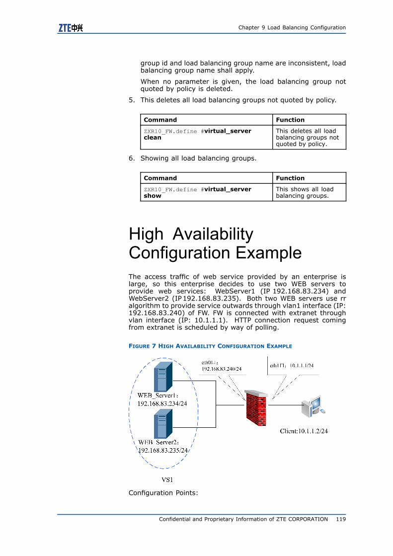
Chapter 9 Load Balancing Configuration
group id and load balancing group name are inconsistent, loadbalancing group name shall apply.
When no parameter is given, the load balancing group notquoted by policy is deleted.
5. This deletes all load balancing groups not quoted by policy.
Command Function
ZXR10_FW.define #virtual_serverclean
This deletes all loadbalancing groups notquoted by policy.
6. Showing all load balancing groups.
Command Function
ZXR10_FW.define #virtual_servershow
This shows all loadbalancing groups.
High AvailabilityConfiguration ExampleThe access traffic of web service provided by an enterprise islarge, so this enterprise decides to use two WEB servers toprovide web services: WebServer1 (IP 192.168.83.234) andWebServer2 (IP192.168.83.235). Both two WEB servers use rralgorithm to provide service outwards through vlan1 interface (IP:192.168.83.240) of FW. FW is connected with extranet throughvlan interface (IP: 10.1.1.1). HTTP connection request comingfrom extranet is scheduled by way of polling.
FIGURE 7 HIGH AVAILABILITY CONFIGURATION EXAMPLE
Configuration Points:
Confidential and Proprietary Information of ZTE CORPORATION 119
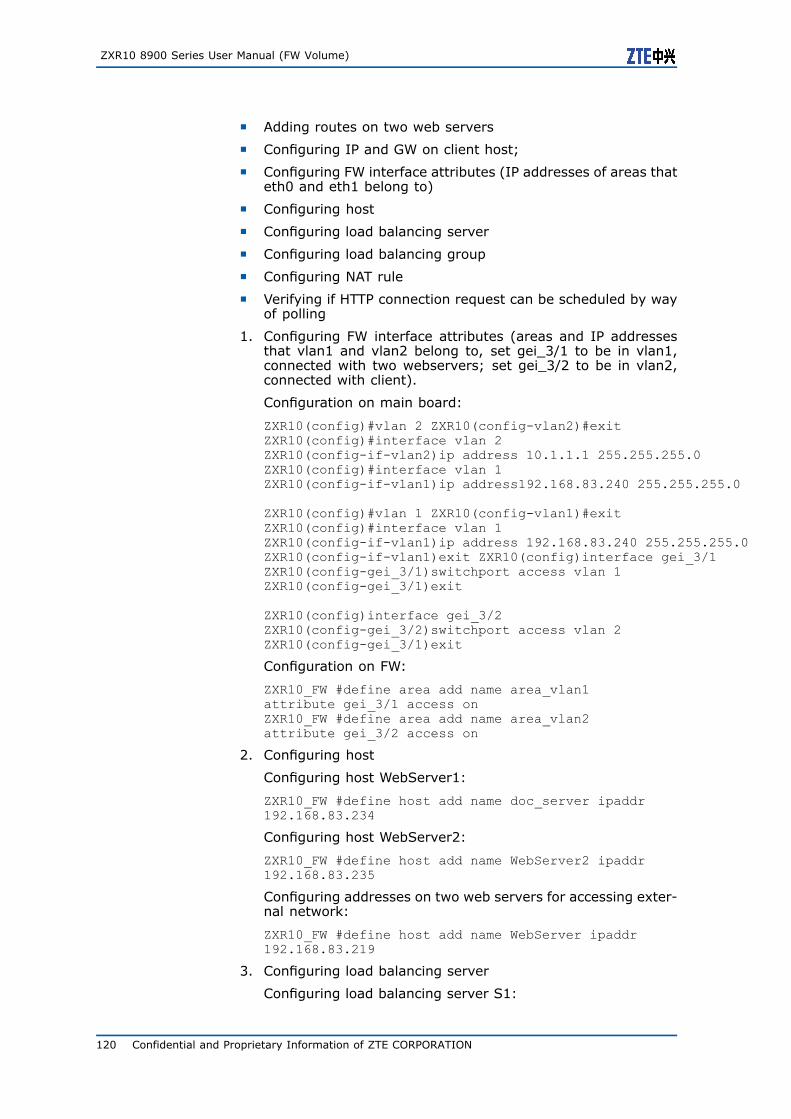
ZXR10 8900 Series User Manual (FW Volume)
� Adding routes on two web servers
� Configuring IP and GW on client host;
� Configuring FW interface attributes (IP addresses of areas thateth0 and eth1 belong to)
� Configuring host
� Configuring load balancing server
� Configuring load balancing group
� Configuring NAT rule
� Verifying if HTTP connection request can be scheduled by wayof polling
1. Configuring FW interface attributes (areas and IP addressesthat vlan1 and vlan2 belong to, set gei_3/1 to be in vlan1,connected with two webservers; set gei_3/2 to be in vlan2,connected with client).
Configuration on main board:
ZXR10(config)#vlan 2 ZXR10(config-vlan2)#exitZXR10(config)#interface vlan 2ZXR10(config-if-vlan2)ip address 10.1.1.1 255.255.255.0ZXR10(config)#interface vlan 1ZXR10(config-if-vlan1)ip address192.168.83.240 255.255.255.0
ZXR10(config)#vlan 1 ZXR10(config-vlan1)#exitZXR10(config)#interface vlan 1ZXR10(config-if-vlan1)ip address 192.168.83.240 255.255.255.0ZXR10(config-if-vlan1)exit ZXR10(config)interface gei_3/1ZXR10(config-gei_3/1)switchport access vlan 1ZXR10(config-gei_3/1)exit
ZXR10(config)interface gei_3/2ZXR10(config-gei_3/2)switchport access vlan 2ZXR10(config-gei_3/1)exit
Configuration on FW:
ZXR10_FW #define area add name area_vlan1attribute gei_3/1 access onZXR10_FW #define area add name area_vlan2attribute gei_3/2 access on
2. Configuring host
Configuring host WebServer1:
ZXR10_FW #define host add name doc_server ipaddr192.168.83.234
Configuring host WebServer2:
ZXR10_FW #define host add name WebServer2 ipaddr192.168.83.235
Configuring addresses on two web servers for accessing exter-nal network:
ZXR10_FW #define host add name WebServer ipaddr192.168.83.219
3. Configuring load balancing server
Configuring load balancing server S1:
120 Confidential and Proprietary Information of ZTE CORPORATION
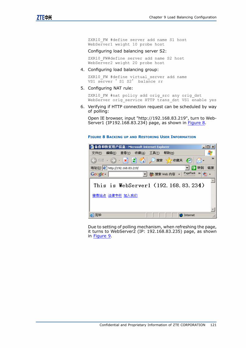
Chapter 9 Load Balancing Configuration
ZXR10_FW #define server add name S1 hostWebServer1 weight 10 probe host
Configuring load balancing server S2:
ZXR10_FW#define server add name S2 hostWebServer2 weight 20 probe host
4. Configuring load balancing group:
ZXR10_FW #define virtual_server add nameVS1 server ’S1 S2’ balance rr
5. Configuring NAT rule:
ZXR10_FW #nat policy add orig_src any orig_dstWebServer orig_service HTTP trans_dst VS1 enable yes
6. Verifying if HTTP connection request can be scheduled by wayof polling:
Open IE browser, input "http://192.168.83.219", turn to Web-Server1 (IP192.168.83.234) page, as shown in Figure 8.
FIGURE 8 BACKING UP AND RESTORING USER INFORMATION
Due to setting of polling mechanism, when refreshing the page,it turns to WebServer2 (IP: 192.168.83.235) page, as shownin Figure 9.
Confidential and Proprietary Information of ZTE CORPORATION 121
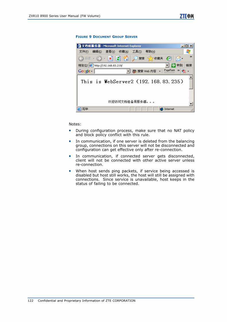
ZXR10 8900 Series User Manual (FW Volume)
FIGURE 9 DOCUMENT GROUP SERVER
Notes:
� During configuration process, make sure that no NAT policyand block policy conflict with this rule.
� In communication, if one server is deleted from the balancinggroup, connections on this server will not be disconnected andconfiguration can get effective only after re-connection.
� In communication, if connected server gets disconnected,client will not be connected with other active server unlessre-connection.
� When host sends ping packets, if service being accessed isdisabled but host still works, the host will still be assigned withconnections. Since service is unavailable, host keeps in thestatus of failing to be connected.
122 Confidential and Proprietary Information of ZTE CORPORATION
C h a p t e r 10
Log and AlarmConfiguration
Table of Contents:Log and Alarm Overview................................................... 123Configuring Logs and Alamrs............................................. 124
Log and Alarm OverviewTo debug, monitor and manage ZXR10 8900 Series Switch FW ser-vice card FW module conveniently, ZXR10 8900 Series Switch FWservice card FWmodule provides log management and alarm func-tion for user. Log and alarm function has three parts:
� Log configuration
� Log Viewing
� Alarm
Log Configuration
ZXR10 8900 Series Switch FW service card FW module providesall-around logging and alarm service functions, which is conve-nient for user tracing working status of ZXR10 8900 Series SwitchFW service card FWmodule. ZXR10 8900 Series Switch FW servicecard FW module can record log in WELF format, transmit the logto preset log server over Syslog protocol, and use the third-partysoftware to perform statistics and analysis to log.
Viewing Log
ZXR10 8900 Series Switch FW service card FW module can bufferpartial log data according to performance of hardware device. Thisis convenient for user to view system log and trace working statusof ZXR10 8900 Series Switch FW service card FW module timely.
Confidential and Proprietary Information of ZTE CORPORATION 123
ZXR10 8900 Series User Manual (FW Volume)
Alarms
ZXR10 8900 Series Switch FW service card FW module has com-prehensive alarm prompt function, supports mail alarming, voicealarming, console alarming and other alarming modes. Firstly,administrator needs to add alarm rules and set alarm objects andparameters. Then set security events triggering alarm rules, in-cluding device faults and administrator predefined security events.When security event occurs, FW will trigger corresponding alarmmessage according to rule.
Configuring Logs and AlamrsConfiguring Log
This topic describes how to configure log.
To access this command module, execute the following command:
#log
To exit from this command module, execute the following com-mand:
#end
1. Setting log server.
Command Function
ZXR10_FW.log #log set ipaddr<ipaddress>[port <string>][ logtype<syslog|welf>][trans<enable|disable>]
This sets log server.
Parameter Description:
Parameter Description
set This sets log server.
ipaddr This set IP address of log server.
<ipaddress> This is one string, indicating IP address.
port This sets port of log server.
<string> This is one string, indicating port id, informat of tcp:80 or udp:80.
logtype This sets log transmission format: syslogor welf
syslog|welf This is log transmission format, syslog bydefault.
124 Confidential and Proprietary Information of ZTE CORPORATION
Chapter 10 Log and Alarm Configuration
Parameter Description
trans This sets whether to transmit log.
enable|disable Enables indicates transmitting log anddisable indicates not transmitting log.
Command Illustration:
Generated log data needs to be managed by log server. Logserver can be any reachable network node (such as PC). Thiscommand can set IP address, port id, transmission format andother information of log server. By default, IP address of logserver is 192.168.1.253, protocol and port id is udp: 514, logtransmission format is syslog, and log is not transmitted.
2. Setting log level.
Command Function
ZXR10_FW.log #log level_set<number>
This sets the levelsat which logs aretransmitted to logserver.
Parameter Description:
Parameter Description
<number> This is one number, indicating log level,ranging from 0 to 8, where 0 indicatesserious errors that cause unavailability ofsystem, 1 indicates alarm messages, 2indicates errors that cause unavailabilityof partial system functions, 3 indicatescommon error messages, 4 indicatesall attacks and unauthorized accesses(except for communication log), 5 indicatesoperation record of administrator, 6indicates common event record, 7 indicatesdebugging information of developer, and 8indicates diagnosis log.
3. Adding log type transmitted to log server.
Command Function
ZXR10_FW.log #log type_set add<string>
This adds log typetransmitted to logserver.
Parameter Description:
Parameter Description
<string> This is one string, indicating log type,including: mgmt, system, pf, conn, ac,secure, dpi, vpn, avse, sslvpn_conn,sslvpn_admin, sslvpn_system, all or none.
4. Deleting log type transmitted to log server.
Confidential and Proprietary Information of ZTE CORPORATION 125
ZXR10 8900 Series User Manual (FW Volume)
Command Function
ZXR10_FW.log #log type_set delete<string>
This deletes log typetransmitted to logserver.
Example 1. To set log server to 192.168.1.25, protocol and port to TCP:524, log transmission type to syslog, and permit log transmis-sion, execute the following command:
ZXR10_FW.log # log set ipaddr 192.168.1.25 port tcp:524logtype syslog trans enable
To transmit level 5 (and below) log to log server, execute thefollowing command:
ZXR10_FW.log # log level_set 5
2. To set log server on each FW where log analysis is needed,execute the following command:
ZXR10_FW.log # log set ipaddr 10.200.2.111 port udp:514logtype syslog trans enable
To set log level, execute the following command:
ZXR10_FW.log # log level_set 6
To set log type to System Running, execute the folloing com-mand:
ZXR10_FW.log # log type_set add system
To show System Running log, execute the following command:
ZXR10_FW.log # log show keyword system from 1 to 10
Viewing Log
This topic describes how to view log.
1. Viewing the total number of logs.
Command Function
ZXR10_FW.log #log count This views the totalnumber of logs.
2. Viewing configuration information of log server.
Command Function
ZXR10_FW.log #log set_show This viewsconfigurationinformation of logserver.
3. Viewing log information.
Command Function
ZXR10_FW.log #log show from<number1> to <number2>[keyword <string>]
This views loginformation.
126 Confidential and Proprietary Information of ZTE CORPORATION
Chapter 10 Log and Alarm Configuration
Parameter Description:
Parameter Description
show This views log information.
from This sets from which log to view.
<number1> This is one number, indicating the numberof log.
to This sets to which log to view.
<number2> This is one number, indicating the numberof log.
keyword This is optional. It sets the keyword in logto view.
<string> This is one string, indicating keyword.
Example To view the total number of logs, execute the following command:
ZXR10_FW.log # log count Total log : 351
To view information of no. 10 to no. 100 logs (containing string"log"), execute the following command:
ZXR10_FW.log # log show from 10 to 100 keyword log
Configuring Alarms
This topic describes how to manage alarming mode.
It is available to trigger alarms according to predefined policies andsecurity alarm events and send alarm messages to administratorby way of mail alarm. User can set related parameters here.
1. Setting event alarming modes according to event types.
Command Function
ZXR10_FW.log #alarmevent set <manage|system|security|policy|communication|hardware|recover|noticetest|all>noticeid <number>| noticename<string>| notice <empty>
This sets eventalarming modesaccording to eventtypes.
Parameter Description:
Parameter Description
set This sets event alarming mode.
<manage|system|security|policy|communication|hardware|recover|noticetest|all>
Manage indicates management systemalarm, system indicates system alarm,security indicates security alarm, policyindicates policy alarm, communicationindicates communication alarm, hardwareindicates hardware alarm, recover indicatesrecover alarm, noticetest indicates testalarm and all indicates alarm of all events.
Confidential and Proprietary Information of ZTE CORPORATION 127
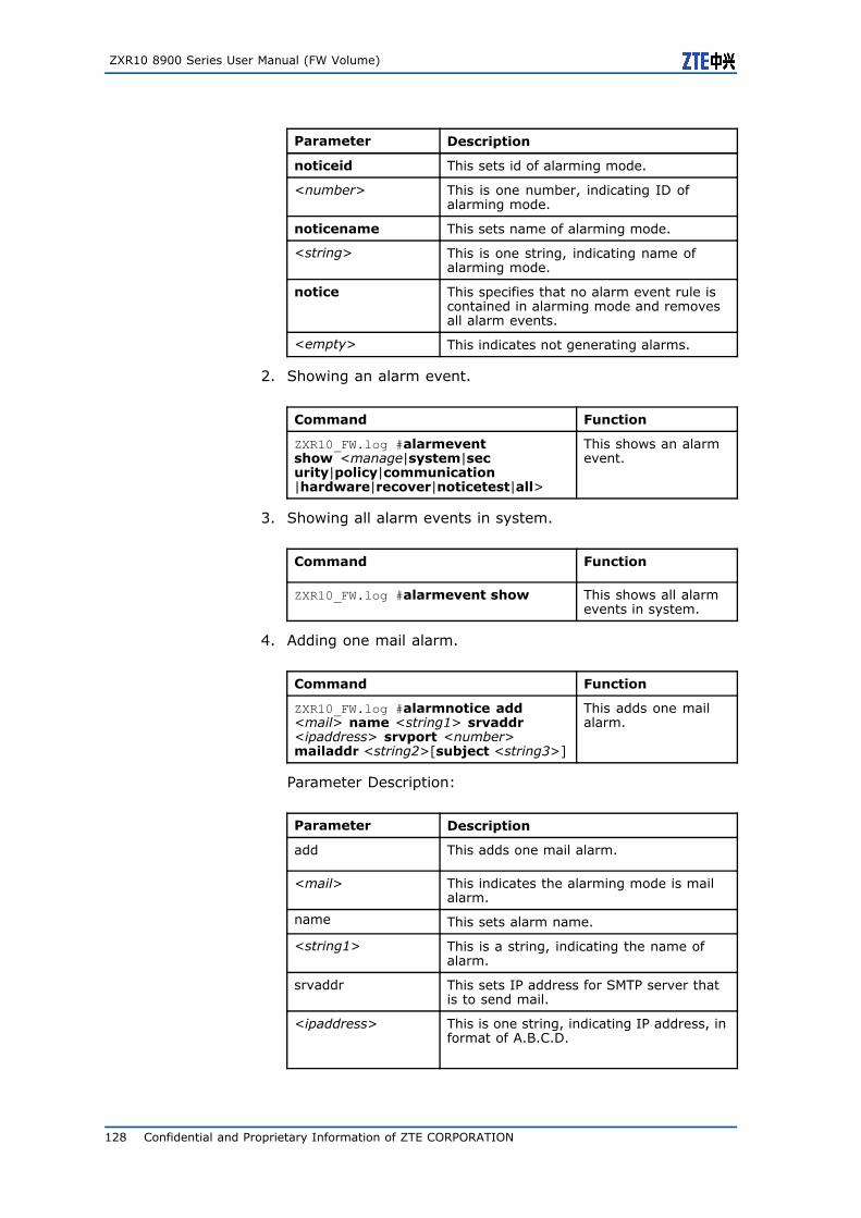
ZXR10 8900 Series User Manual (FW Volume)
Parameter Description
noticeid This sets id of alarming mode.
<number> This is one number, indicating ID ofalarming mode.
noticename This sets name of alarming mode.
<string> This is one string, indicating name ofalarming mode.
notice This specifies that no alarm event rule iscontained in alarming mode and removesall alarm events.
<empty> This indicates not generating alarms.
2. Showing an alarm event.
Command Function
ZXR10_FW.log #alarmeventshow <manage|system|security|policy|communication|hardware|recover|noticetest|all>
This shows an alarmevent.
3. Showing all alarm events in system.
Command Function
ZXR10_FW.log #alarmevent show This shows all alarmevents in system.
4. Adding one mail alarm.
Command Function
ZXR10_FW.log #alarmnotice add<mail> name <string1> srvaddr<ipaddress> srvport <number>mailaddr <string2>[subject <string3>]
This adds one mailalarm.
Parameter Description:
Parameter Description
add This adds one mail alarm.
<mail> This indicates the alarming mode is mailalarm.
name This sets alarm name.
<string1> This is a string, indicating the name ofalarm.
srvaddr This sets IP address for SMTP server thatis to send mail.
<ipaddress> This is one string, indicating IP address, informat of A.B.C.D.
128 Confidential and Proprietary Information of ZTE CORPORATION
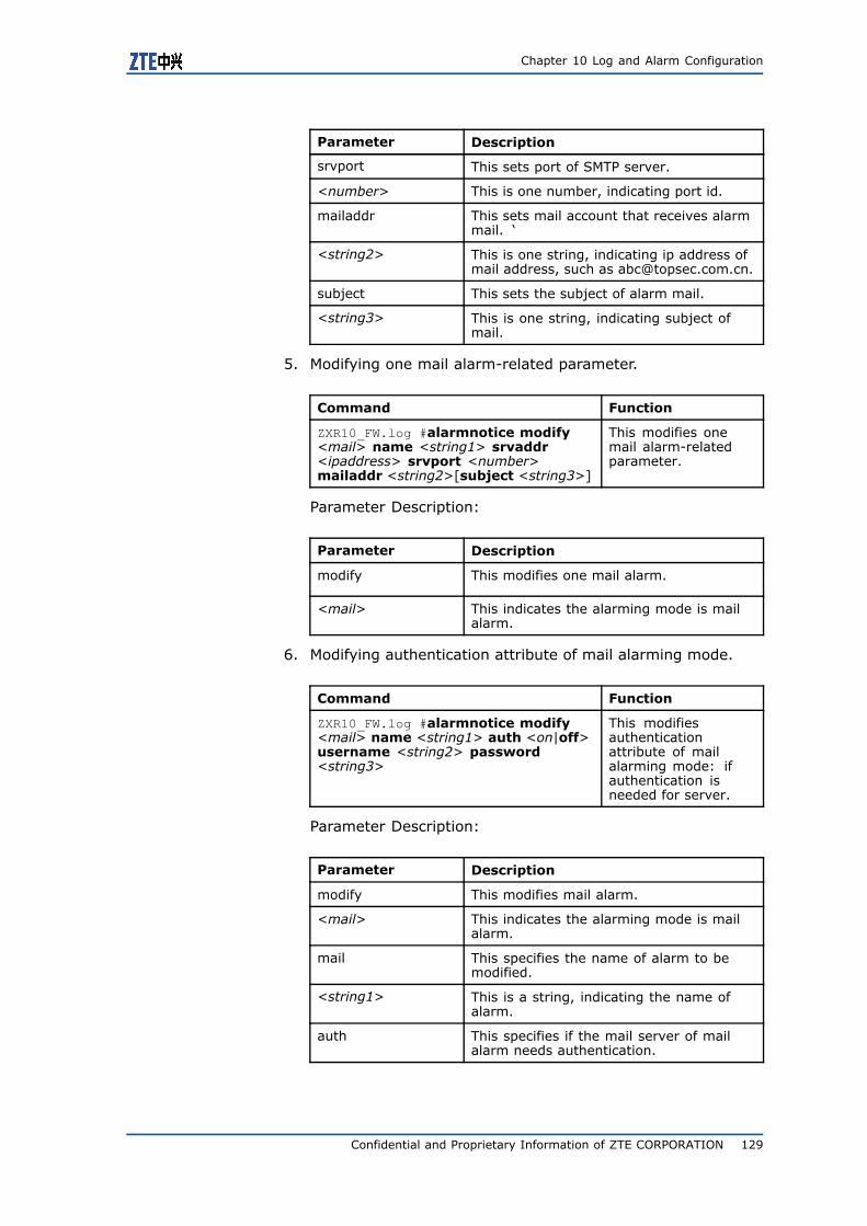
Chapter 10 Log and Alarm Configuration
Parameter Description
srvport This sets port of SMTP server.
<number> This is one number, indicating port id.
mailaddr This sets mail account that receives alarmmail. ‘
<string2> This is one string, indicating ip address ofmail address, such as [email protected].
subject This sets the subject of alarm mail.
<string3> This is one string, indicating subject ofmail.
5. Modifying one mail alarm-related parameter.
Command Function
ZXR10_FW.log #alarmnotice modify<mail> name <string1> srvaddr<ipaddress> srvport <number>mailaddr <string2>[subject <string3>]
This modifies onemail alarm-relatedparameter.
Parameter Description:
Parameter Description
modify This modifies one mail alarm.
<mail> This indicates the alarming mode is mailalarm.
6. Modifying authentication attribute of mail alarming mode.
Command Function
ZXR10_FW.log #alarmnotice modify<mail> name <string1> auth <on|off>username <string2> password<string3>
This modifiesauthenticationattribute of mailalarming mode: ifauthentication isneeded for server.
Parameter Description:
Parameter Description
modify This modifies mail alarm.
<mail> This indicates the alarming mode is mailalarm.
mail This specifies the name of alarm to bemodified.
<string1> This is a string, indicating the name ofalarm.
auth This specifies if the mail server of mailalarm needs authentication.
Confidential and Proprietary Information of ZTE CORPORATION 129
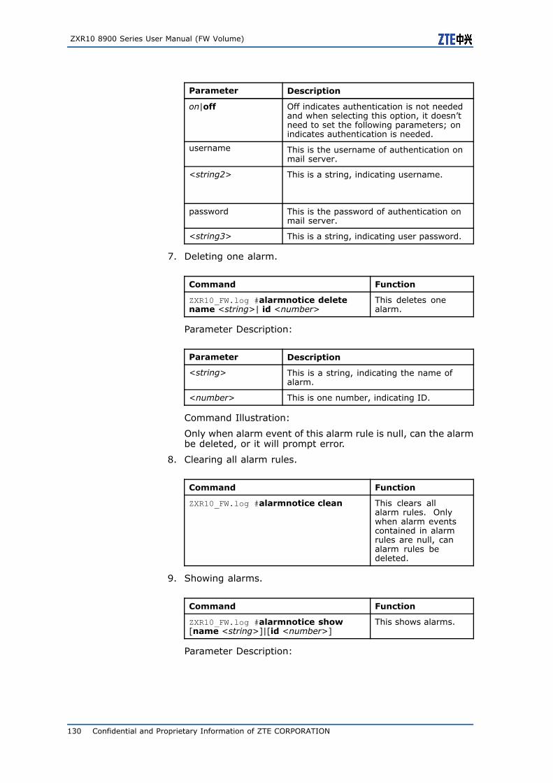
ZXR10 8900 Series User Manual (FW Volume)
Parameter Description
on|off Off indicates authentication is not neededand when selecting this option, it doesn’tneed to set the following parameters; onindicates authentication is needed.
username This is the username of authentication onmail server.
<string2> This is a string, indicating username.
password This is the password of authentication onmail server.
<string3> This is a string, indicating user password.
7. Deleting one alarm.
Command Function
ZXR10_FW.log #alarmnotice deletename <string>| id <number>
This deletes onealarm.
Parameter Description:
Parameter Description
<string> This is a string, indicating the name ofalarm.
<number> This is one number, indicating ID.
Command Illustration:
Only when alarm event of this alarm rule is null, can the alarmbe deleted, or it will prompt error.
8. Clearing all alarm rules.
Command Function
ZXR10_FW.log #alarmnotice clean This clears allalarm rules. Onlywhen alarm eventscontained in alarmrules are null, canalarm rules bedeleted.
9. Showing alarms.
Command Function
ZXR10_FW.log #alarmnotice show[name <string>]|[id <number>]
This shows alarms.
Parameter Description:
130 Confidential and Proprietary Information of ZTE CORPORATION
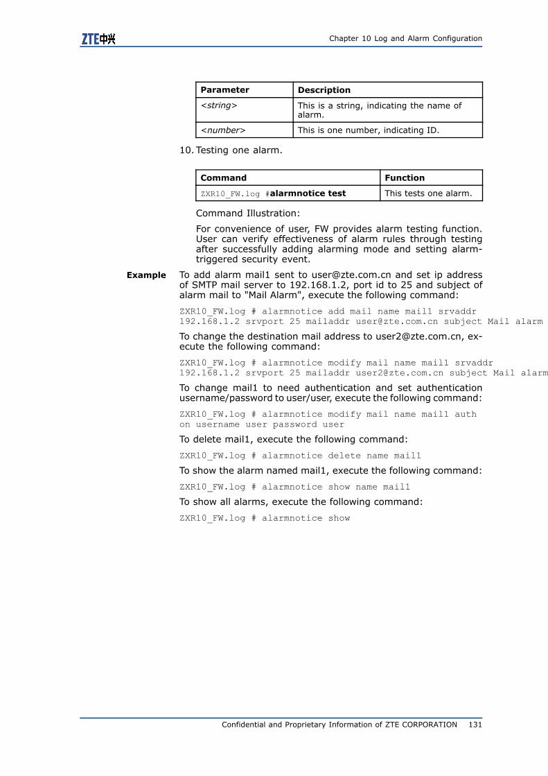
Chapter 10 Log and Alarm Configuration
Parameter Description
<string> This is a string, indicating the name ofalarm.
<number> This is one number, indicating ID.
10. Testing one alarm.
Command Function
ZXR10_FW.log #alarmnotice test This tests one alarm.
Command Illustration:
For convenience of user, FW provides alarm testing function.User can verify effectiveness of alarm rules through testingafter successfully adding alarming mode and setting alarm-triggered security event.
Example To add alarm mail1 sent to [email protected] and set ip addressof SMTP mail server to 192.168.1.2, port id to 25 and subject ofalarm mail to "Mail Alarm", execute the following command:
ZXR10_FW.log # alarmnotice add mail name mail1 srvaddr192.168.1.2 srvport 25 mailaddr [email protected] subject Mail alarm
To change the destination mail address to [email protected], ex-ecute the following command:
ZXR10_FW.log # alarmnotice modify mail name mail1 srvaddr192.168.1.2 srvport 25 mailaddr [email protected] subject Mail alarm
To change mail1 to need authentication and set authenticationusername/password to user/user, execute the following command:
ZXR10_FW.log # alarmnotice modify mail name mail1 authon username user password user
To delete mail1, execute the following command:
ZXR10_FW.log # alarmnotice delete name mail1
To show the alarm named mail1, execute the following command:
ZXR10_FW.log # alarmnotice show name mail1
To show all alarms, execute the following command:
ZXR10_FW.log # alarmnotice show
Confidential and Proprietary Information of ZTE CORPORATION 131

ZXR10 8900 Series User Manual (FW Volume)
This page is intentionally blank.
132 Confidential and Proprietary Information of ZTE CORPORATION
Figures
Figure 1 Packet Filtering Configuration Example.....................74
Figure 2 Access Control Rule Configuration Example One ........82
Figure 3 Access Control Rule Configuration Example Two ........84
Figure 4 Address-Based Source Address Translation
Configuration Example .......................................96
Figure 5 IP Address-Based Destination Address Translation
Configuration Example .......................................97
Figure 6 Port-Based Destination Address Translation
Configuration Example .......................................98
Figure 7 High Availability Configuration Example .................. 119
Figure 8 Backing up and Restoring User Information ............ 121
Figure 9 Document Group Server....................................... 122
Confidential and Proprietary Information of ZTE CORPORATION 133

ZXR10 8900 Series User Manual (FW Volume)
This page is intentionally blank.
134 Confidential and Proprietary Information of ZTE CORPORATION

Tables
Confidential and Proprietary Information of ZTE CORPORATION 135

ZXR10 8900 Series User Manual (FW Volume)
This page is intentionally blank.
136 Confidential and Proprietary Information of ZTE CORPORATION
Glossary
DPI - Deep Packet Inspection
FTP - File Transfer Protocol
IP - Internet Protocol
IPv4 - Internet Protocol version 4
MAC - Media Access Control
NAT - Network Address Translation
NTP - Network Time Protocol
PPTP - PPP Tunnel Protocol
RSTP - Rapid Spanning Tree Protocol
TELNET - Telecommunication Network Protocol
TFTP - Trivial File Transfer Protocol
VLAN - Virtual Local Area Network
VPN - Virtual Private Network
Confidential and Proprietary Information of ZTE CORPORATION 137