Embed Size (px)
Citation preview

ZP2 Series Operation Manual
P/N 501-405203-2-31 • REV 03.10 • ISS 07NOV13

Copyright © 2013 UTC Fire & Security. All rights reserved.
Trademarks and patents
ZP2 Series is a trademark of UTC Fire & Security.
Other trade names used in this document may be trademarks or registered trademarks of the manufacturers or vendors of the respective products.
Manufacturer UTC CCS Manufacturing Polska Sp. Z o.o. Ul. Kolejowa 24. 39-100 Ropczyce, Poland
Authorized EU manufacturing representative: UTC Fire & Security B.V. Kelvinstraat 7, 6003 DH Weert, Netherlands
Version This document covers control panels with firmware version 3.0 or later.
Certification
European Union directives
1999/5/EC (R&TTE directive): Hereby, UTC Fire & Security declares that this device is in compliance with the essential requirements and other relevant provisions of Directive 1999/5/EC.
2004/108/EC (EMC directive).
2002/96/EC (WEEE directive): Products marked with this symbol cannot be disposed of as unsorted municipal waste in the European Union. For proper recycling, return this product to your local supplier upon the purchase of equivalent new equipment, or dispose of it at designated collection points. For more information see: www.recyclethis.info.
2006/66/EC (battery directive): This product contains a battery that cannot be disposed of as unsorted municipal waste in the European Union. See the product documentation for specific battery information. The battery is marked with this symbol, which may include lettering to indicate cadmium (Cd), lead (Pb), or mercury (Hg). For proper recycling, return the battery to your supplier or to a designated collection point. For more information see: www.recyclethis.info.
Contact information For contact information, see www.utcfssecurityproducts.eu.
ZP2 Series Operation Manual i
Content
Important information i Limitation of liability i Advisory messages i
Introduction 1 Firmware compatibility 1 Fire alarm and repeater panels 1
Product overview 3 The user interface 3 Front panel controls and indicators 5 LCD controls and indicators 9 Acoustic indicators 11 Conditions 11 Status indications 12
Control panel operation 16 User levels 16 Operation controls and procedures 17 Public level operation 18 Operator level operation 20
Maintenance 25
Menu maps 26
Regulatory information 27

ii ZP2 Series Operation Manual
ZP2 Series Operation Manual i
Important information
Limitation of liability To the maximum extent permitted by applicable law, in no event will UTCFS be liable for any lost profits or business opportunities, loss of use, business interruption, loss of data, or any other indirect, special, incidental, or consequential damages under any theory of liability, whether based in contract, tort, negligence, product liability, or otherwise. Because some jurisdictions do not allow the exclusion or limitation of liability for consequential or incidental damages the preceding limitation may not apply to you. In any event the total liability of UTCFS shall not exceed the purchase price of the product. The foregoing limitation will apply to the maximum extent permitted by applicable law, regardless of whether UTCFS has been advised of the possibility of such damages and regardless of whether any remedy fails of its essential purpose.
Installation in accordance with this manual, applicable codes, and the instructions of the authority having jurisdiction is mandatory.
While every precaution has been taken during the preparation of this manual to ensure the accuracy of its contents, UTCFS assumes no responsibility for errors or omissions.
Advisory messages Advisory messages alert you to conditions or practices that can cause unwanted results. The advisory messages used in this document are shown and described below.
WARNING: Warning messages advise you of hazards that could result in injury or loss of life. They tell you which actions to take or to avoid in order to prevent the injury or loss of life.
Caution: Caution messages advise you of possible equipment damage. They tell you which actions to take or to avoid in order to prevent the damage. Note: Note messages advise you of the possible loss of time or effort. They describe how to avoid the loss. Notes are also used to point out important information that you should read.

ii ZP2 Series Operation Manual

ZP2 Series Operation Manual 1
Introduction This is the operation manual for the ZP2-F Series fire alarm, repeater, and evacuation control panels. Read these instructions and all related documentation entirely before operating this product.
Firmware compatibility Information in this document covers control panels with firmware version 3.0 or later. This document must not be used as a guide to operation of control panels with an earlier firmware version.
To check the firmware version of your control panel, see the Revision report in the Reports menu. For more information, see “Viewing reports” on page 22.
Fire alarm and repeater panels The series includes the fire alarm, repeater, and evacuation panels shown below.
Table 1: Fire alarm, repeater, and evacuation panels
Model Description
ZP2-E1(-S) [1] One-loop addressable fire and evacuation alarm control panel
ZP2-E2(-S) Two-loop addressable fire and evacuation alarm control panel
ZP2-ER(-S) Addressable fire and evacuation alarm repeater panel
ZP2-F1(-S) One-loop addressable fire alarm control panel
ZP2-F1-FB2(-S) One-loop addressable fire alarm control panel with fire routing and fire protection controls
ZP2-F1-SC(-S) One-loop addressable fire alarm control panel with fire routing and fire protection controls [2]
ZP2-F1-SCFB(-S) One-loop addressable SS 3654 fire alarm control panel with fire routing and fire protection controls
ZP2-F2(-S) Two-loop addressable fire alarm control panel
ZP2-F2-PRT Two-loop addressable fire alarm control panel with internal printer
ZP2-F2-FB2(-S) Two-loop addressable fire alarm control panel with fire routing and fire protection controls
ZP2-F2-FB2-PRT Two-loop addressable fire alarm control panel with fire routing and fire protection controls and internal printer
ZP2-F2-SC(-S) Two-loop addressable fire alarm control panel with fire routing and fire protection controls [2]
ZP2-F2-SCFB(-S) Two-loop addressable SS 3654 fire alarm control panel with fire routing and fire protection controls
ZP2-F2-SCFB-PRT Two-loop addressable SS 3654 fire alarm control panel with fire routing and fire protection controls and internal printer
ZP2-FR(-S) Addressable fire alarm repeater panel
2 ZP2 Series Operation Manual
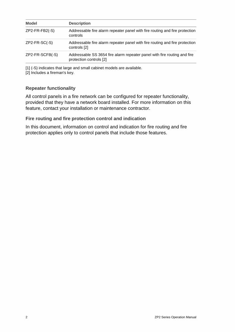
Model Description
ZP2-FR-FB2(-S) Addressable fire alarm repeater panel with fire routing and fire protection controls
ZP2-FR-SC(-S) Addressable fire alarm repeater panel with fire routing and fire protection controls [2]
ZP2-FR-SCFB(-S) Addressable SS 3654 fire alarm repeater panel with fire routing and fire protection controls [2]
[1] (-S) indicates that large and small cabinet models are available. [2] Includes a fireman's key.
Repeater functionality All control panels in a fire network can be configured for repeater functionality, provided that they have a network board installed. For more information on this feature, contact your installation or maintenance contractor.
Fire routing and fire protection control and indication In this document, information on control and indication for fire routing and fire protection applies only to control panels that include those features.
ZP2 Series Operation Manual 3
Product overview This topic provides an introduction to the control panel user interface, LCD, operator controls, and indicators.
For a detailed overview of front panel controls and indicators, see “Front panel controls and indicators” on page 5.
The user interface
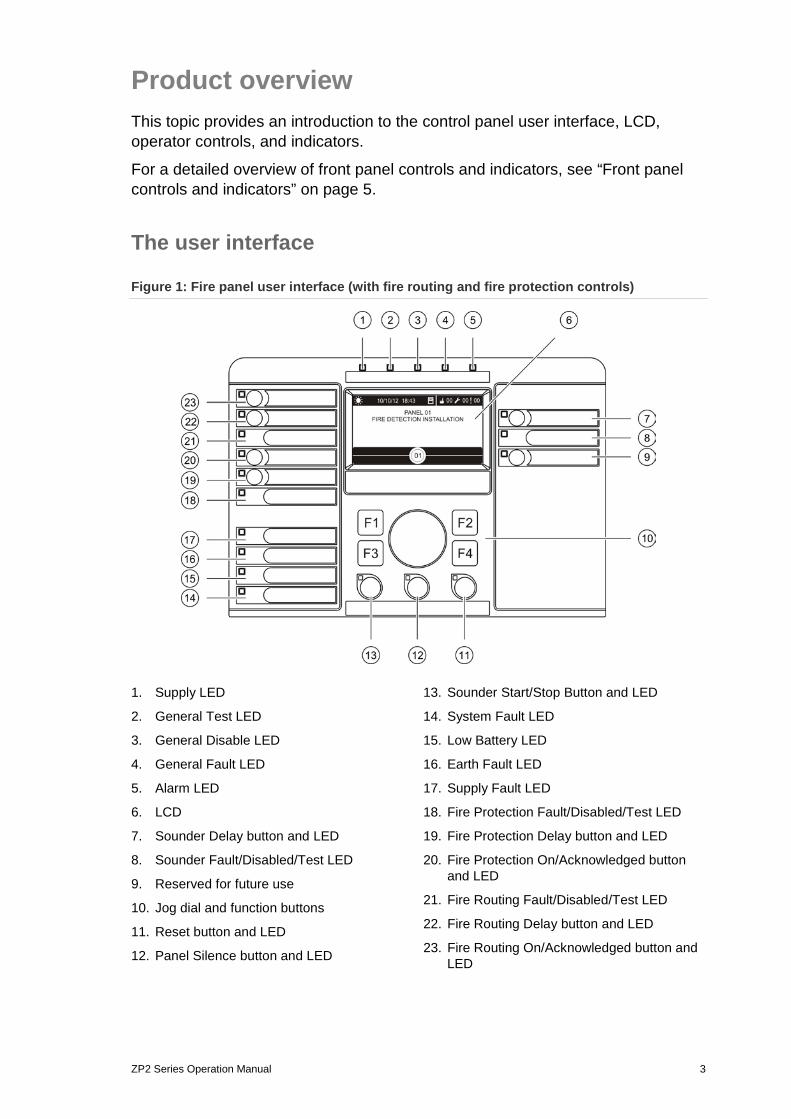
Figure 1: Fire panel user interface (with fire routing and fire protection controls)
1. Supply LED
2. General Test LED
3. General Disable LED
4. General Fault LED
5. Alarm LED
6. LCD
7. Sounder Delay button and LED
8. Sounder Fault/Disabled/Test LED
9. Reserved for future use
10. Jog dial and function buttons
11. Reset button and LED
12. Panel Silence button and LED
13. Sounder Start/Stop Button and LED
14. System Fault LED
15. Low Battery LED
16. Earth Fault LED
17. Supply Fault LED
18. Fire Protection Fault/Disabled/Test LED
19. Fire Protection Delay button and LED
20. Fire Protection On/Acknowledged button and LED
21. Fire Routing Fault/Disabled/Test LED
22. Fire Routing Delay button and LED
23. Fire Routing On/Acknowledged button and LED
4 ZP2 Series Operation Manual
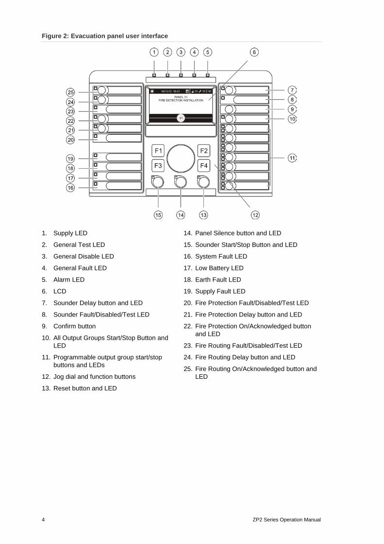
Figure 2: Evacuation panel user interface
1. Supply LED
2. General Test LED
3. General Disable LED
4. General Fault LED
5. Alarm LED
6. LCD
7. Sounder Delay button and LED
8. Sounder Fault/Disabled/Test LED
9. Confirm button
10. All Output Groups Start/Stop Button and LED
11. Programmable output group start/stop buttons and LEDs
12. Jog dial and function buttons
13. Reset button and LED
14. Panel Silence button and LED
15. Sounder Start/Stop Button and LED
16. System Fault LED
17. Low Battery LED
18. Earth Fault LED
19. Supply Fault LED
20. Fire Protection Fault/Disabled/Test LED
21. Fire Protection Delay button and LED
22. Fire Protection On/Acknowledged button and LED
23. Fire Routing Fault/Disabled/Test LED
24. Fire Routing Delay button and LED
25. Fire Routing On/Acknowledged button and LED

ZP2 Series Operation Manual 5
Configuration options Depending on your configuration, the labels for some interface buttons may change. See Table 2 below.
Table 2: Configured changes to interface buttons and LEDs
Item EN 54 NEN 2575
10 All Output Groups Start/Stop All Evacuation Start/Stop
11 Programmable output group start/stop Evacuation area sounders start/stop
15 Sounder Start/Stop Fire Sounder Start/Stop
Note: For more information on the operations associated with the programmable buttons, contact your installation or maintenance contractor.
Front panel controls and indicators Operational features described in this section are not available to all users. More information on control panel operation and access restrictions can be found in the topic “User levels” on page 16.
Common controls and indicators The table below includes information for the common controls and indicators available for fire, repeater, and evacuation panels.
Table 3: Common controls and indicators
Control/LED LED colour Description
Supply LED Green Indicates that the system is powered up.
General Test LED Yellow Indicates that one or more features or devices are being tested.
General Disable LED Yellow Indicates that one or more features or devices are disabled.
General Fault LED Yellow Indicates a general fault. The fault LED for the corresponding device or feature also flashes.
Alarm LED Red Indicates a fire alarm.
A flashing LED indicates that the alarm was activated by a detector. A steady LED indicates that the alarm was activated by a manual call point.
Fire Routing On/Acknowledged button and LED
Red Cancels a previously configured delay as it counts down and activates fire routing.
A flashing LED indicates that fire routing has been activated. A steady LED indicates that the fire routing signal has been acknowledged by the remote monitoring equipment.
6 ZP2 Series Operation Manual
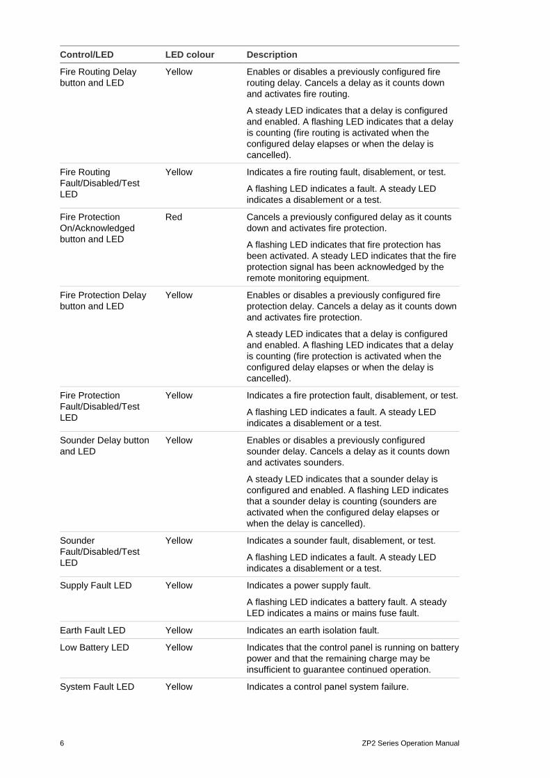
Control/LED LED colour Description
Fire Routing Delay button and LED
Yellow Enables or disables a previously configured fire routing delay. Cancels a delay as it counts down and activates fire routing.
A steady LED indicates that a delay is configured and enabled. A flashing LED indicates that a delay is counting (fire routing is activated when the configured delay elapses or when the delay is cancelled).
Fire Routing Fault/Disabled/Test LED
Yellow Indicates a fire routing fault, disablement, or test.
A flashing LED indicates a fault. A steady LED indicates a disablement or a test.
Fire Protection On/Acknowledged button and LED
Red Cancels a previously configured delay as it counts down and activates fire protection.
A flashing LED indicates that fire protection has been activated. A steady LED indicates that the fire protection signal has been acknowledged by the remote monitoring equipment.
Fire Protection Delay button and LED
Yellow Enables or disables a previously configured fire protection delay. Cancels a delay as it counts down and activates fire protection.
A steady LED indicates that a delay is configured and enabled. A flashing LED indicates that a delay is counting (fire protection is activated when the configured delay elapses or when the delay is cancelled).
Fire Protection Fault/Disabled/Test LED
Yellow Indicates a fire protection fault, disablement, or test.
A flashing LED indicates a fault. A steady LED indicates a disablement or a test.
Sounder Delay button and LED
Yellow Enables or disables a previously configured sounder delay. Cancels a delay as it counts down and activates sounders.
A steady LED indicates that a sounder delay is configured and enabled. A flashing LED indicates that a sounder delay is counting (sounders are activated when the configured delay elapses or when the delay is cancelled).
Sounder Fault/Disabled/Test LED
Yellow Indicates a sounder fault, disablement, or test.
A flashing LED indicates a fault. A steady LED indicates a disablement or a test.
Supply Fault LED Yellow Indicates a power supply fault.
A flashing LED indicates a battery fault. A steady LED indicates a mains or mains fuse fault.
Earth Fault LED Yellow Indicates an earth isolation fault.
Low Battery LED Yellow Indicates that the control panel is running on battery power and that the remaining charge may be insufficient to guarantee continued operation.
System Fault LED Yellow Indicates a control panel system failure.
ZP2 Series Operation Manual 7
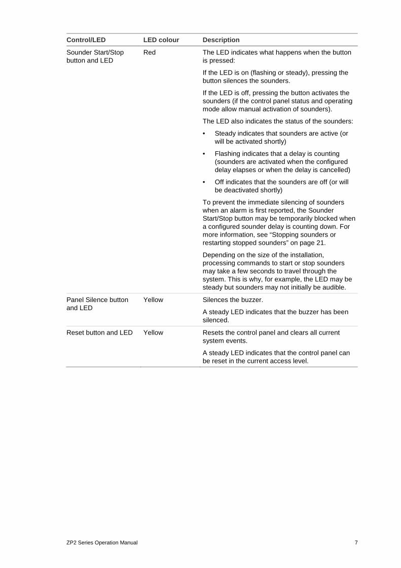
Control/LED LED colour Description
Sounder Start/Stop button and LED
Red The LED indicates what happens when the button is pressed:
If the LED is on (flashing or steady), pressing the button silences the sounders.
If the LED is off, pressing the button activates the sounders (if the control panel status and operating mode allow manual activation of sounders).
The LED also indicates the status of the sounders:
• Steady indicates that sounders are active (or will be activated shortly)
• Flashing indicates that a delay is counting (sounders are activated when the configured delay elapses or when the delay is cancelled)
• Off indicates that the sounders are off (or will be deactivated shortly)
To prevent the immediate silencing of sounders when an alarm is first reported, the Sounder Start/Stop button may be temporarily blocked when a configured sounder delay is counting down. For more information, see “Stopping sounders or restarting stopped sounders” on page 21.
Depending on the size of the installation, processing commands to start or stop sounders may take a few seconds to travel through the system. This is why, for example, the LED may be steady but sounders may not initially be audible.
Panel Silence button and LED
Yellow Silences the buzzer.
A steady LED indicates that the buzzer has been silenced.
Reset button and LED Yellow Resets the control panel and clears all current system events.
A steady LED indicates that the control panel can be reset in the current access level.
8 ZP2 Series Operation Manual
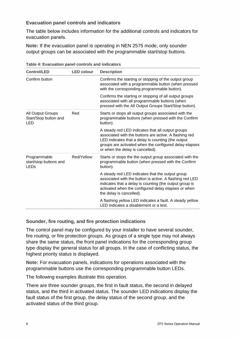
Evacuation panel controls and indicators The table below includes information for the additional controls and indicators for evacuation panels.
Note: If the evacuation panel is operating in NEN 2575 mode, only sounder output groups can be associated with the programmable start/stop buttons.
Table 4: Evacuation panel controls and indicators
Control/LED LED colour Description
Confirm button Confirms the starting or stopping of the output group associated with a programmable button (when pressed with the corresponding programmable button).
Confirms the starting or stopping of all output groups associated with all programmable buttons (when pressed with the All Output Groups Start/Stop button).
All Output Groups Start/Stop button and LED
Red Starts or stops all output groups associated with the programmable buttons (when pressed with the Confirm button).
A steady red LED indicates that all output groups associated with the buttons are active. A flashing red LED indicates that a delay is counting (the output groups are activated when the configured delay elapses or when the delay is cancelled).
Programmable start/stop buttons and LEDs
Red/Yellow Starts or stops the the output group associated with the programmable button (when pressed with the Confirm button).
A steady red LED indicates that the output group associated with the button is active. A flashing red LED indicates that a delay is counting (the output group is activated when the configured delay elapses or when the delay is cancelled).
A flashing yellow LED indicates a fault. A steady yellow LED indicates a disablement or a test.
Sounder, fire routing, and fire protection indications The control panel may be configured by your installer to have several sounder, fire routing, or fire protection groups. As groups of a single type may not always share the same status, the front panel indications for the corresponding group type display the general status for all groups. In the case of conflicting status, the highest priority status is displayed.
Note: For evacuation panels, indications for operations associated with the programmable buttons use the corresponding programmable button LEDs.
The following examples illustrate this operation.
There are three sounder groups, the first in fault status, the second in delayed status, and the third in activated status. The sounder LED indications display the fault status of the first group, the delay status of the second group, and the activated status of the third group.
ZP2 Series Operation Manual 9
There are two fire routing groups, the first is in activated status and the second is in acknowledged status. The fire routing indication displays the acknowledged status but not the activation status (the acknowledgement status takes priority).
For more information on your control panel configuration and indications, contact your installation or maintenance contractor.
LCD controls and indicators
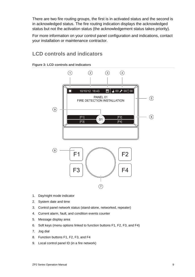
Figure 3: LCD controls and indicators
1. Day/night mode indicator
2. System date and time
3. Control panel network status (stand-alone, networked, repeater)
4. Current alarm, fault, and condition events counter
5. Message display area
6. Soft keys (menu options linked to function buttons F1, F2, F3, and F4)
7. Jog dial
8. Function buttons F1, F2, F3, and F4
9. Local control panel ID (in a fire network)

10 ZP2 Series Operation Manual
Icons displayed on the LCD Icons displayed on the LCD are shown below.
Table 5: LCD icons and descriptions
Icon Description
Day mode (network)
This icon indicates that the primary sensitivity mode setting for control panels in the fire network is day mode.
Day mode (control panel)
This icon indicates that the sensitivity mode for the local control panel is day mode. Other control panels in the fire network may have a different sensitivity mode setting.
Night mode (network)
This icon indicates that the primary sensitivity mode setting for control panels in the fire network is night mode.
Night mode (control panel)
This icon indicates that the sensitivity mode for the local control panel is night mode. Other control panels in the fire network may have a different sensitivity mode setting.
Fire alarms
The number beside this icon indicates the number of zones with an active fire alarm. Alarm information for the first and last zones to report an alarm is displayed in the LCD message area.
Faults
The number beside this icon indicates the number of active faults. Additional information is available by pressing F1 (Show Events).
Conditions
The number beside this icon indicates the number of active system conditions (events). Additional information is available by pressing F1 (Show Events).
Stand-alone
This icon indicates that the control panel is not connected to the fire network.
Networked
This icon indicates that the control panel is connected to the fire network.
Repeater
This icon indicates that the control panel is configured to operate as a repeater and is connected to the fire network.
Detector alarm [1] This icon indicates a detector alarm.
Manual call point alarm [1] This icon indicates a manual call point alarm.
Manual call point alarm (sprinkler) [1]
This icon indicates a manual call point alarm (sprinkler).
Manual call point alarm (“hausalarm”) [1]
This icon indicates a manual call point alarm (“hausalarm”). This is a local alarm with no fire routing activation.
[1] These icons appear in the message display area with the notification details.

ZP2 Series Operation Manual 11
Indication of remote and local events on the LCD The local control panel ID is always displayed on the LCD (see Figure 2 on page 4).
If your control panel forms part of a fire network, the event notification includes the panel ID reporting the event as follows:
• If the panel ID matches the local ID, then the event relates to the local control panel.
• If the panel ID does not match the local ID, then the event is reported by the remote control panel with the panel ID indicated.
Acoustic indicators The control panel uses the following acoustic indicators to highlight system events.
Table 6: Control panel acoustic indicators
Indication Description
The buzzer sounds continuously Indicates a fire alarm or a system fault
The buzzer sounds intermittently (long tone) [1] Indicates all other faults
The buzzer sounds intermittently (short tone) [1] Indicates a condition
[1] A long tone is 50% ON and 50% OFF. A short tone is 25% ON and 75% OFF.
Conditions A summary of system events logged as conditions is shown below.
Table 7: System events logged as conditions
Condition type Description
Alert A device is in alarm but the system is waiting for an additional alarm event to confirm the zone alarm
Configuration device connected A control panel configuration session is initiated via an external device (PC, laptop, etc.)
Date and time not set The system started but the date and time are not set
Disablements A control panel feature or device is disabled
Event log full The control panel event log is full
Extinguishing status [1] Extinguishing is blocked, disabled, or has a fault
Extinguishing I/O device [1] An extinguishing I/O device is active, being tested, is disabled, or has a fault
Input activation An input is activated (subject to configuration)
Loop device not configured A loop device is detected that is not configured
Maximum conventional zones exceeded in a network
The number of conventional zones in a fire network exceeds the maximum allowed (64)

12 ZP2 Series Operation Manual
Condition type Description
Maximum loops exceeded in a network
The number of loops in a fire network exceeds the maximum allowed (32)
New node in the fire network A control panel has been added to the fire network
Output group activation An output group is activated
Prealarm A device (and corresponding zone) is in prealarm
Sounder, fire routing, and fire protection delays
A sounder, fire routing, or fire protection delay is enabled or disabled
Tests A control panel feature or device is being tested
[1] These condition types only apply if an extinguishing panel is included in the fire network.
Status indications This section includes a summary of the control panel status indications.
Standby Standby is indicated as follows:
• The Supply LED is steady
• If a sounder delay has been enabled the Sounder Delay LED is steady
• If a fire routing delay has been enabled the Fire Routing Delay LED is steady
• If a fire protection delay has been enabled the Fire Protection Delay LED is steady
Note: Depending on your fire system configuration the buzzer may sound intermittently to indicate an enabled delay condition.
Fire alarm In accordance with European standards, fire alarm status is indicated on the control panel LCD by zone (and not by device).
When an alarm is reported in more than one zone, the LCD displays two zone messages: the first for the first zone to report an alarm and the second for the most recent zone to report an alarm, as shown below.
Figure 4: Fire alarm indication on the control panel LCD

ZP2 Series Operation Manual 13
Each zone message indicates:
• The zone identifier and description, the timestamp, and the device description of the first alarm reported in the zone
• A counter with the total number of devices in alarm in the zone.
To see the details of the devices in alarm, press F1 (Show Events) and select Alarms. Then select the corresponding zone reporting the alarm. A list of devices in alarm for the zone is displayed.
Additional fire alarm status indications are:
• The control panel Alarm LED flashes if the alarm is activated by a detector or is steady if it is activated by a manual call point.
• If a zone board is installed and the corresponding zone is included on the zone board, then the zone alarm LED is flashing or steady (depending on the source of the alarm).
• If a sounder delay has been enabled the Sounder Delay LED is steady.
• The Sounder Delay LED flashes while the delay is counting.
• The Sounder Start/Stop LED indicates the Sounder Start/Stop button status (disabled, not disabled) and the status of the sounders (see Table 3 on page 5 for more information).
• If a fire routing delay has been enabled the Fire Routing Delay LED is steady. The Fire Routing Delay LED flashes while the delay is counting.
• When fire routing is activated, the Fire Routing ON/Acknowledged LED flashes. If configured to do so by your installation or maintenance contractor, a steady Fire Routing ON/Acknowledged LED indicates that the fire routing signal has been acknowledged by the remote monitoring equipment.
• If a fire protection delay has been enabled the Fire Protection Delay LED is steady. The Fire Protection Delay LED flashes while the delay is counting.
• When fire protection is activated, the Fire Protection ON/Acknowledged LED flashes. If configured to do so by your installation or maintenance contractor, a steady Fire Protection ON/Acknowledged LED indicates that the fire protection signal has been acknowledged by the remote monitoring equipment.
• Alarm information for the first and last zones to report an alarm is displayed on the LCD.
• The control panel buzzer sounds continuously.
Alarms activated by a manual call point always take priority over alarms activated by a detector. When an alarm is activated by both devices, the Alarm LED is steady.

14 ZP2 Series Operation Manual
Evacuation If your control panel is configured for evacuation control, evacuation is indicated as follows:
• The Confirm LED is steady.
• The evacuation area alarm LED is steady if an evacuation alarm is active or flashing if a confirmation delay is counting.
• The All Evacuation Start/Stop LED is steady if an evacuation alarm is active for all configured evacuation areas.
Note: Evacuation panels only. This feature is subject to previous configuration by your installation or maintenance contractor and operations associated with programmable buttons and LEDs may differ from those described here.
Fault Fault status is indicated as follows:
• The General Fault LED is steady and the corresponding feature or device fault LED (if there is one) flashes.
• Mains and battery power faults are indicated by a flashing General Fault LED and Supply Fault LED. Additional information about the fault is displayed on the LCD.
• Earth faults are indicated by a flashing General Fault LED and a flashing Earth Fault LED.
• System faults are indicated by a flashing General Fault LED and a steady System Fault LED.
• Low battery faults are indicated by a flashing General Fault LED and a steady Low Battery LED.
• Additional information about the fault is displayed on the LCD.
• The control panel buzzer sounds intermittently (long tone).
Note: Always contact your installation or maintenance contractor to investigate the cause of a fault.
Disablement Disablements are indicated as follows:
• The General Disable LED is steady and the corresponding feature or device disable LED (if there is one) is flashing
• If a zone board is installed, the corresponding zone Disabled/Test LED is steady (if the corresponding zone is included on the zone board)
• The control panel buzzer sounds intermittently (short tone)
For more information on the disablement, press F1 (Show Events) and then select Conditions.
ZP2 Series Operation Manual 15
Test Tests are indicated as follows:
• The General Test LED is steady
• If a zone board is installed, the corresponding zone Disabled/Test LED is steady (if the corresponding zone is included on the zone board)
• The control panel buzzer sounds intermittently (short tone)
For more information on the test, press F1 (Show Events) and then select Conditions.
Low battery
WARNING: This is a critical indication and your property may not be fully protected. If your control panel indicates low battery, contact your installation or maintenance contractor immediately and ask them to restore power or, if this is not possible, to replace the batteries.
Low battery indicates that the control panel is running on battery power and that the remaining charge may be insufficient for continued operation.
Low battery is indicated as follows:
• The General Fault LED is flashing
• The Low battery LED is steady
• An initial warning message indicating the low battery status is displayed on the LCD
• If the power issue is not fixed, the batteries will continue to discharge until a second warning message is displayed indicating that the control panel will shut down
• The buzzer sounds intermittently (long tone)
When the batteries are completely discharged, the control panel shuts down to protect the batteries and there are no further indications.
If power is re-established before the control panel shuts down, the control panel returns to its former status. If not, the control panel date and time must be reconfigured once power is restored.
Notes
• Customers who wish to obtain maximum standby time from batteries (24 to 72 hours) may see this fault indication.
• A low battery indication means that the batteries are discharged and does not indicate that they are defective.

16 ZP2 Series Operation Manual
Control panel operation
User levels Access to some of the features of this product is restricted by the user level assigned to a user account.
Public
The public level is the default user level.
This level allows basic operational tasks, such as responding to a fire alarm or fault warning at the control panel. No password is required.
See “Public level operation” on page 18 for more information.
Operator The operator level allows additional operational tasks and is reserved for authorized users who have been trained to operate the control panel. The default password for the default operator user is 2222.
See “Operator level operation” on page 20 for more information.
Restricted user levels Restricted user levels are protected by password security. You are required to enter the username and password assigned to you by your maintenance or installation contractor.
The control panel automatically exits from a restricted user level and reverts to the public user level after two minutes if no button is pressed.
To enter a restricted user level:
1. Press F4 (Main menu). The username and password prompt appears on the LCD.
2. Select your username and enter your password by turning the jog dial clockwise or anticlockwise. Press the jog dial to confirm each entry.
When a correct four-digit password has been entered, the LCD displays the Main menu for your assigned user level.
Note: Your maintenance or installation contractor may have configured the control panel to remember the last login details entered.
To exit a restricted user level:
1. Press F3 (Logout) from the Main menu.

ZP2 Series Operation Manual 17
Operation controls and procedures Using the function buttons and the jog dial
Use function buttons F1 to F4 and the jog dial (see Figure 3 on page 9) to navigate the LCD menus, to select menu options, and to enter passwords and system information, as shown below. Entering passwords and system information
Turn the jog dial clockwise or anticlockwise to enter passwords and other system information. Press the jog dial to confirm an entry.
Selecting soft keys from the LCD menu
Press the function buttons F1 to F4 to select the corresponding menu options (Main menu, Logout, Exit etc.).
Navigating and confirming menu selections
Turn the jog dial clockwise or anticlockwise to select an option from the on-screen menu. Press the jog dial to confirm the selection.
The control panel ID on the LCD is white text with a dark background when the jog dial is active (the control panel is waiting for input).
Configuration options The options listed below are available when making configuration changes to the control panel (for example, changing the password).
The control panel configuration (and configuration revision) is only updated when configuration changes are applied by pressing F3 (Apply).
The configuration revision change and timestamp are recorded in the Revision report and can be accessed at operator level (see “Viewing reports” on page 22).
Table 8: Configuration control options and keys
Option Key Description
Save F1 Saves the current configuration change without applying it immediately.
Apply F3 Applies the current configuration change and all stored (saved) configuration changes. The control panel will reset automatically.
Discard F4 Discards all stored (saved) configuration changes that have not been applied.
Exit F2 Exits the configuration process without storing or applying the current configuration change.
Note: When updating multiple configuration settings, we recommend that you save after each change and then apply all changes from the Main menu.
18 ZP2 Series Operation Manual
Public level operation Public level operations are those that can be performed by any user. No password is required to perform tasks at this level.
This user level lets you:
• Silence the buzzer • Cancel an active sounder, fire routing, or fire protection delay • Start evacuation sounders • View current events • View support information
Silencing the buzzer To silence the control panel buzzer, press the Panel Silence button. A steady Panel Silence LED indicates that the buzzer was silenced.
Note: Depending on the control panel configuration, the buzzer may re-sound for each new event reported.
Cancelling an active sounder delay If a sounder delay is enabled and active (counting down), press the Sounder Delay button to cancel the delay and activate sounders immediately.
A sounder delay is indicated as follows:
• A steady Sounder Delay LED indicates that a delay is enabled
• A flashing Sounder Delay LED during a fire alarm indicates that the configured delay is active (sounders are activated when the configured delay elapses or when the delay is cancelled)
A fire alarm activated by a manual call point overrides any configured delay and activates the sounders immediately.
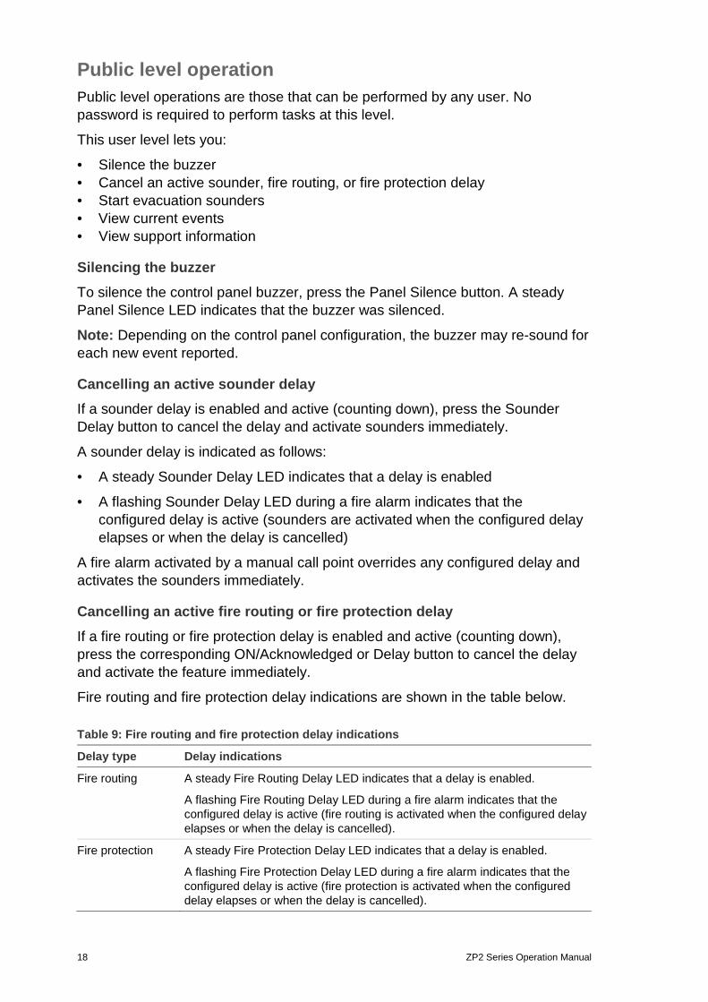
Cancelling an active fire routing or fire protection delay If a fire routing or fire protection delay is enabled and active (counting down), press the corresponding ON/Acknowledged or Delay button to cancel the delay and activate the feature immediately.
Fire routing and fire protection delay indications are shown in the table below.
Table 9: Fire routing and fire protection delay indications
Delay type Delay indications
Fire routing A steady Fire Routing Delay LED indicates that a delay is enabled.
A flashing Fire Routing Delay LED during a fire alarm indicates that the configured delay is active (fire routing is activated when the configured delay elapses or when the delay is cancelled).
Fire protection A steady Fire Protection Delay LED indicates that a delay is enabled.
A flashing Fire Protection Delay LED during a fire alarm indicates that the configured delay is active (fire protection is activated when the configured delay elapses or when the delay is cancelled).
ZP2 Series Operation Manual 19
Note: A fire alarm activated by a manual call point overrides any configured delay and activates fire routing or fire protection immediately (if configured).
Starting evacuation sounders To start the evacuation sounders for a single evacuation area, press the corresponding evacuation area Start/Stop button, and then press Confirm.
To start the evacuation sounders for all evacuation areas, press the All Evacuation Start/Stop button, and then press Confirm.
A steady evacuation area alarm LED indicates that the evacuation sounders are active (sounding). A flashing evacuation area alarm LED indicates that a configured delay is counting down and that sounders will activate when the delay elapses.
Note: Evacuation panels only. This feature is subject to previous configuration by your installation or maintenance contractor and operations associated with programmable buttons and LEDs may differ from those described here.
Viewing current events To view current event information, press F1 (Show events) and then select the event type to view.
The event types available to this user level are:
• Alarms
• Alerts
• Faults
• Conditions
Alerts are device alarms that require confirmation from another configured alarm event before an alarm is indicated at the control panel.
Conditions include all other system events. Examples: tests and disablements in the fire system.
Viewing support information To view support information configured by your installation or maintenance contractor, press F3 (Support). Your installer or maintenance contractor may configure, for example, contact information or different messages to display in alarm and non-alarm situations.
Note: This information is only available if your installation or maintenance contractor has included it in the fire system configuration.
20 ZP2 Series Operation Manual
Operator level operation The operator level is protected by password security and is reserved for authorized users who have been trained to operate the control panel. The default operator user password is 2222.
This user level lets you:
• Perform all tasks described in “Public level operation” on page 18 • Reset the control panel • Manually start sounders, stop sounders, or restart stopped sounders • Manually stop evacuation sounders • Enable or disable previously configured sounder, fire routing, and fire
protection delays • View system status reports • Change the operator password • Perform LED, LCD, buzzer, and keyboard tests • View the alarm counter
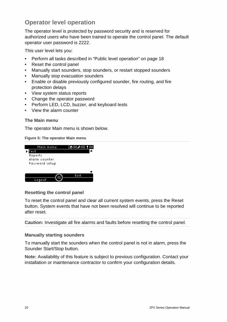
The Main menu The operator Main menu is shown below.
Figure 5: The operator Main menu
Resetting the control panel To reset the control panel and clear all current system events, press the Reset button. System events that have not been resolved will continue to be reported after reset.
Caution: Investigate all fire alarms and faults before resetting the control panel.
Manually starting sounders To manually start the sounders when the control panel is not in alarm, press the Sounder Start/Stop button.
Note: Availability of this feature is subject to previous configuration. Contact your installation or maintenance contractor to confirm your configuration details.
ZP2 Series Operation Manual 21
Stopping sounders or restarting stopped sounders To stop the sounders, press the Sounder Start/Stop button. To restart stopped sounders, press the button again.
A steady Sounder Start/Stop LED indicates that the sounders are active (sounding). A flashing Sounder Start/Stop LED indicates that a configured sounder delay is counting down and that sounders can be silenced (before activation) by pressing the Sounder Start/Stop button.
Sounder functionality is subject to previous configuration and, depending on what your installation or maintenance contractor has selected, silenced sounders may restart automatically if another alarm event is detected.
Contact your installation or maintenance contractor to confirm all configuration details for your site.
If the Sounder Start/Stop button is disabled To prevent the immediate silencing of sounders when an alarm is first reported, the Sounder Start/Stop button may be temporarily disabled for a preconfigured period of time when a configured sounder delay is counting down. The default disable time for the Sounders Start/Stop button is 60 seconds.
The disable time starts to count down when the control panel enters alarm status and the configured sounder delay starts.
During the configured disable time the Sounder Start/Stop LED is off and the sounders cannot be silenced (before activation) by pressing the Sounder Start/Stop button.
In the time between the end of the configured disable time and the end of the configured sounder delay (when the Sounder Start/Stop LED is flashing), pressing the Sounder Start/Stop button silences sounders (before activation).
A configured sounder delay may still be cancelled while the delay is running (and sounders activated) by pressing the Sounder Delay button.
Manually stopping evacuation sounders To stop the evacuation sounders for a single evacuation area, press the corresponding evacuation area Start/Stop button, and then press Confirm.
To stop the evacuation sounders for all evacuation areas, press the All Evacuation Start/Stop button, and then press Confirm.
Note: Evacuation panels only. This feature is subject to previous configuration by your installation or maintenance contractor and operations associated with programmable buttons and LEDs may differ from those described here.
Enabling or disabling a previously configured sounder, fire routing, or fire protection delay To enable a previously configured sounder, fire routing, or fire protection delay, press the corresponding Sounder, Fire Routing, or Fire Protection Delay button. To disable the delay, press the button again.

22 ZP2 Series Operation Manual
Note: Availability of this feature is subject to previous configuration and its functionality may vary for each zone. Contact your installation or maintenance contractor to confirm all configuration details for your site.
Viewing reports To view system status reports for the control panel and connected devices, select Reports from the Main menu. Report information for this user level is shown in the table below.
Table 10: Reports available to operator users
Report Description
Event log Displays all alarm, fault, and condition events logged by the control panel
Attention required Displays all devices reporting a fault condition
Revision Displays your control panel software revision, control panel configuration revision, and system boards serial number data
Contact details Displays contact information for your installation or maintenance contractor (subject to installer configuration)
Zone status [1] Displays the current status information for zones
Device status [1] Displays the current status information for control panel devices
Panel I/O status Displays the current status information for the control panel inputs and outputs
Output groups status [1] Displays the control panel output groups (sounders, fire routing, fire protection, or program) that are currently active
Rules status Displays the control panel rules that are currently active
Firenet status Displays the current status for all control panels in the fire network
[1] These reports are not available on repeater panels. [2] A rule consists of one or more states (combined by Boolean operators) that are configured to trigger specific system actions after a specific confirmation time. Rules are created by your installation or maintenance contractor.
Note: To check the firmware version of your control panel, select Revision report and then select Firmware version.
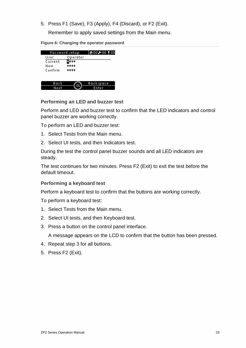
Changing your password Use the Password setup menu to change your password.
To change your password:
1. Select Password setup from the Main menu, and then select Change password.
2. Enter your current password.
3. Enter and then confirm your new password.
4. Press F4 (Enter), and then press F1 (Back).
ZP2 Series Operation Manual 23
5. Press F1 (Save), F3 (Apply), F4 (Discard), or F2 (Exit).
Remember to apply saved settings from the Main menu.
Figure 6: Changing the operator password
Performing an LED and buzzer test Perform and LED and buzzer test to confirm that the LED indicators and control panel buzzer are working correctly.
To perform an LED and buzzer test:
1. Select Tests from the Main menu.
2. Select UI tests, and then Indicators test.
During the test the control panel buzzer sounds and all LED indicators are steady.
The test continues for two minutes. Press F2 (Exit) to exit the test before the default timeout.
Performing a keyboard test Perform a keyboard test to confirm that the buttons are working correctly.
To perform a keyboard test:
1. Select Tests from the Main menu.
2. Select UI tests, and then Keyboard test.
3. Press a button on the control panel interface.
A message appears on the LCD to confirm that the button has been pressed.
4. Repeat step 3 for all buttons.
5. Press F2 (Exit).

24 ZP2 Series Operation Manual
Performing an LCD test Perform an LCD test to confirm that the LCD is working correctly.
To perform an LCD test:
1. Select Tests from the Main menu.
2. Select UI tests, and then LCD test.
A test pattern displays on the LCD to help identify the location of defective pixels.
3. Press F2 (Exit).
Viewing the alarm counter Select the Alarm counter option to view the total number of fire alarms recorded by the control panel. The alarm counter value cannot be reset.
ZP2 Series Operation Manual 25
Maintenance To ensure the correct functioning of your control panel and fire alarm system, and to comply with all European regulations, perform scheduled maintenance as described below.
Quarterly maintenance Contact your installation or maintenance contractor to carry out a quarterly inspection of the fire alarm system.
This inspection must test at least one device per zone and verify that the control panel responds to all fault and alarm events.
Annual maintenance Contact your installation or maintenance contractor to carry out an annual inspection of the fire alarm system.
This inspection must test all system devices and verify that the control panel responds to all fault and alarm events. All electrical connections must be visually inspected to make sure that they are securely fastened, that they have not been damaged, and that they are appropriately protected.
Cleaning Keep the outside and inside of the control panel clean. Carry out periodic cleaning using a damp cloth for the outside. Do not use products containing solvents to clean the unit. Do not clean the inside of the cabinet with liquid products.
26 ZP2 Series Operation Manual
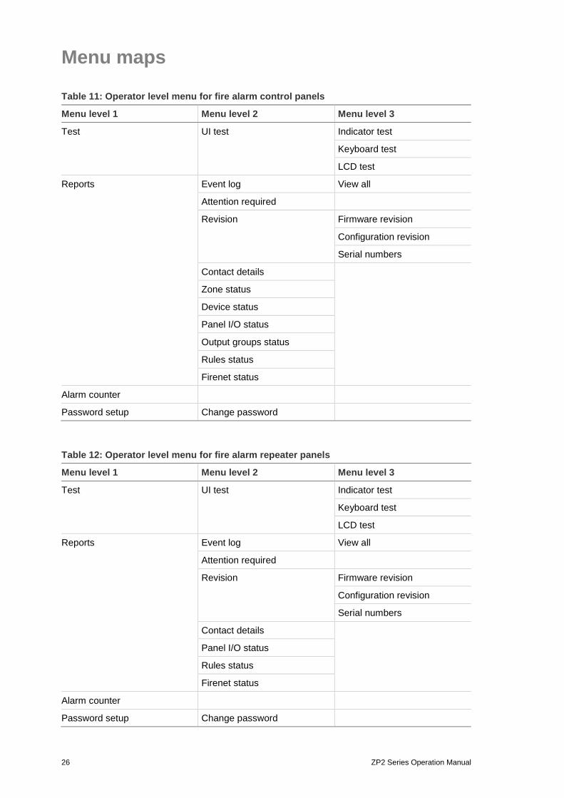
Menu maps
Table 11: Operator level menu for fire alarm control panels
Menu level 1 Menu level 2 Menu level 3
Test UI test Indicator test
Keyboard test
LCD test
Reports Event log View all
Attention required
Revision Firmware revision
Configuration revision
Serial numbers
Contact details
Zone status
Device status
Panel I/O status
Output groups status
Rules status
Firenet status
Alarm counter
Password setup Change password
Table 12: Operator level menu for fire alarm repeater panels
Menu level 1 Menu level 2 Menu level 3
Test UI test Indicator test
Keyboard test
LCD test
Reports Event log View all
Attention required
Revision Firmware revision
Configuration revision
Serial numbers
Contact details
Panel I/O status
Rules status
Firenet status
Alarm counter
Password setup Change password
ZP2 Series Operation Manual 27
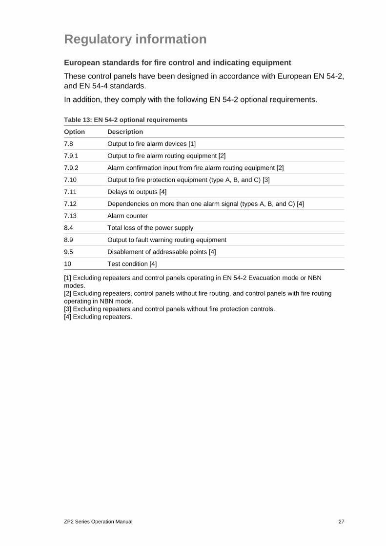
Regulatory information European standards for fire control and indicating equipment These control panels have been designed in accordance with European EN 54-2, and EN 54-4 standards.
In addition, they comply with the following EN 54-2 optional requirements.
Table 13: EN 54-2 optional requirements
Option Description
7.8 Output to fire alarm devices [1]
7.9.1 Output to fire alarm routing equipment [2]
7.9.2 Alarm confirmation input from fire alarm routing equipment [2]
7.10 Output to fire protection equipment (type A, B, and C) [3]
7.11 Delays to outputs [4]
7.12 Dependencies on more than one alarm signal (types A, B, and C) [4]
7.13 Alarm counter
8.4 Total loss of the power supply
8.9 Output to fault warning routing equipment
9.5 Disablement of addressable points [4]
10 Test condition [4]
[1] Excluding repeaters and control panels operating in EN 54-2 Evacuation mode or NBN modes. [2] Excluding repeaters, control panels without fire routing, and control panels with fire routing operating in NBN mode. [3] Excluding repeaters and control panels without fire protection controls. [4] Excluding repeaters.
28 ZP2 Series Operation Manual
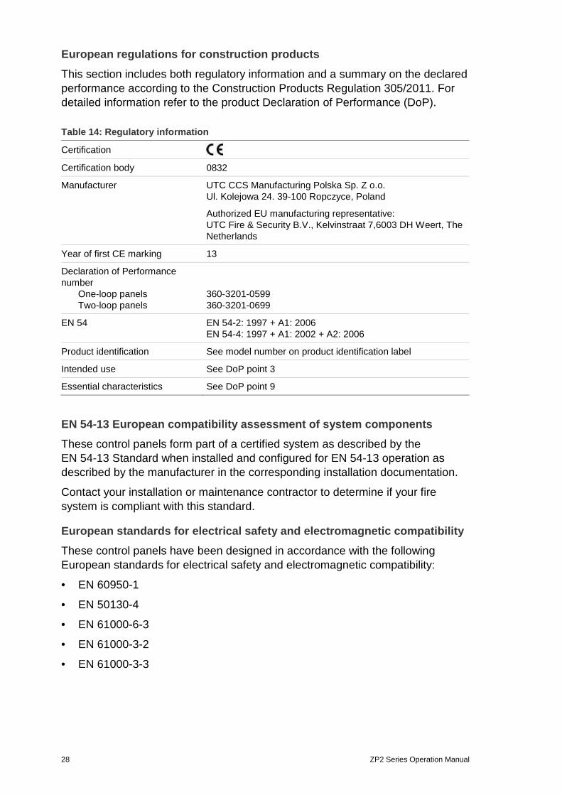
European regulations for construction products
This section includes both regulatory information and a summary on the declared performance according to the Construction Products Regulation 305/2011. For detailed information refer to the product Declaration of Performance (DoP).
Table 14: Regulatory information
Certification Certification body 0832
Manufacturer UTC CCS Manufacturing Polska Sp. Z o.o. Ul. Kolejowa 24. 39-100 Ropczyce, Poland
Authorized EU manufacturing representative: UTC Fire & Security B.V., Kelvinstraat 7,6003 DH Weert, The Netherlands
Year of first CE marking 13
Declaration of Performance number One-loop panels Two-loop panels
360-3201-0599 360-3201-0699
EN 54 EN 54-2: 1997 + A1: 2006 EN 54-4: 1997 + A1: 2002 + A2: 2006
Product identification See model number on product identification label
Intended use See DoP point 3
Essential characteristics See DoP point 9
EN 54-13 European compatibility assessment of system components These control panels form part of a certified system as described by the EN 54-13 Standard when installed and configured for EN 54-13 operation as described by the manufacturer in the corresponding installation documentation.
Contact your installation or maintenance contractor to determine if your fire system is compliant with this standard.
European standards for electrical safety and electromagnetic compatibility These control panels have been designed in accordance with the following European standards for electrical safety and electromagnetic compatibility:
• EN 60950-1
• EN 50130-4
• EN 61000-6-3
• EN 61000-3-2
• EN 61000-3-3

ZP2 Series Operation Manual 29