Embed Size (px)
Citation preview
tekmarNet® Thermostat 553
Installation & Operation Manual
553_D04/13
Zoning Replaces: New
© 2013 553_D - 04/131 of 48A Watts Water Technologies Company
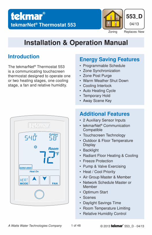
The tekmarNet® Thermostat 553 is a communicating touchscreen thermostat designed to operate one or two heating stages, one cooling stage, a fan and relative humidity.
Introduction Energy Saving FeaturesProgrammable Schedule
Zone Synchronization
Zone Post Purge
Warm Weather Shut Down
Cooling Interlock
Auto Heating Cycle
Temporary Hold
Away Scene Key
•
•
•
•
•
•
•
•
Additional Features2 Auxiliary Sensor Inputs
tekmarNet® Communication Compatible
Touchscreen Technology
Outdoor & Floor Temperature Display
Backlight
Radiant Floor Heating & Cooling
Freeze Protection
Pump & Valve Exercising
Heat / Cool Priority
Air Group Master & Member
Network Schedule Master or Member
Optimum Start
Scenes
Daylight Savings Time
Room Temperature Limiting
Relative Humidity Control
•
•
•
•
•
•
•
•
•
•
•
•
•
•
•
•
© 2013 553_D - 04/132 of 48A Watts Water Technologies Company
Congratulations on the purchase of your new tekmar® thermostat.
This manual will step through the complete installation, programming and sequence of operation for this control. At the back, there are tips for control and system troubleshooting.
Getting Started
Table of Contents
Getting Started ...............................2
Installation ...........................................3
Caution ............................................3
Preparation .....................................3
Removing The Thermostat Base ....3
Mounting The Thermostat Base .....4
Thermostat Wiring ..........................4
Compatible Sensors .......................5
Testing the Thermostat Wiring ........5
Mounting the Thermostat ................6
Switch Settings ....................................7
User Interface ......................................8
Home Screen ..................................8
Symbols Description .......................8
Programmable Settings .......................9
Programming Menus ......................9
Set Temp Menu ........................10-13
Time Menu ....................................14
Schedule Menu ........................15-16
Display Menu ........................... 16-17
Scenes Menu ................................17
Monitor Menu ...........................18-21
Toolbox Menu ..........................21-23
Setup Menu............................. 24-30
Sequence of Operation ......................31
Heat and Cool Applications ..........31
Heating Operation .........................31
Cooling Operation .........................33
Room Min and Max Limits ............33
Mode Operation ............................34
Pump and Valve Operation ...........34
Fan Operation ...............................35
Relative Humidity Operation .........35
Air Group Operation......................37
Time Clock ....................................37
Temperature Adjustment ..............38
Programmable Schedules ............39
Scenes (System Override) ............40
Secondary Temperature Display ..41
Access Levels ...............................42
tekmarNet® Address .....................42
Cleaning the Thermostat ..............42
Troubleshooting .................................43
Error Messages ...................... 43-47
Technical Data ..............................47
Limited Warranty and Product Return Procedure .........................48
© 2013 553_D - 04/133 of 48A Watts Water Technologies Company
Preparation
tekmar or jeweller screwdriver
Phillips head screwdriver
•
•
Wire Stripper•Tools Required ------------------------------------------------------ ------------------------------------------------------
Materials Required -------------------------------------------------- --------------------------------------------------18 AWG LVT Solid Wire (Low Voltage Connections)
•
Installation
Choose the placement of the thermostats early in the construction process to enable
proper wiring during rough-in.
Consider the following:
Interior Wall.
Keep dry. Avoid potential leakage onto the control.
Relative Humidity less than 90%. Non-condensing environment.
No exposure to extreme temperatures beyond 32-122°F (0-50°C).
No draft, direct sun, or other cause for inaccurate temperature readings.
Away from equipment, appliances, or other sources of electrical interference.
Easy access for wiring, viewing, and adjusting the display screen.
Approximately 5 feet (1.5 m) off the finished floor.
The maximum length of wire is 500 feet (150 m).
Strip wire to 3/8” (10 mm) for all terminal connections.
Use standard 8 conductor, 18 AWG wire.
•
•
•
•
•
•
•
•
•
•
•
Installation Location ------------------------------------------------- -------------------------------------------------
CautionImproper installation and operation of this control could result in damage to the equipment and possibly even personal injury or death. It is your responsibility to ensure that this control is safely installed according to all applicable codes and standards. This electronic control is not intended for use as a primary limit control. Other controls that are intended and certified as safety limits must be placed into the control circuit.
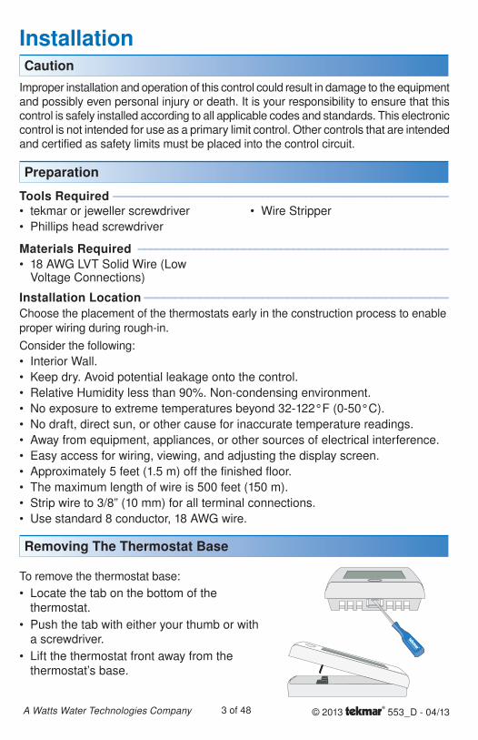
Removing The Thermostat Base
To remove the thermostat base:
Locate the tab on the bottom of the thermostat.
Push the tab with either your thumb or with a screwdriver.
Lift the thermostat front away from the thermostat’s base.
•
•
•
© 2013 553_D - 04/134 of 48A Watts Water Technologies Company
Thermostat WiringThe thermostat can be wired in three different ways.
Stand Alone - Similar to tekmarNet®4 wiring with tN4 wiring terminal not used. First stage heating relay (Rh - W1) can be wired directly to switching relays.
tekmarNet®4 - Allows the thermostat to be wired using 4 wires to a tN4 Wiring Center or Zone Manager. The tN4 communication bus can also be daisy-chained to allow multiple thermostats to be connected together without home running wires back to the mechanical room.
tekmarNet®2 - Allows the thermostat to be wired point-to-point using 2 wires to a tN2 Wiring Center, House Control, or Zone Manager. This allows easy wiring for retrofit applications.
Application specific wiring diagrams are provided in the 553_A brochure.
Wall
StudThermostatFront
ThermostatBase
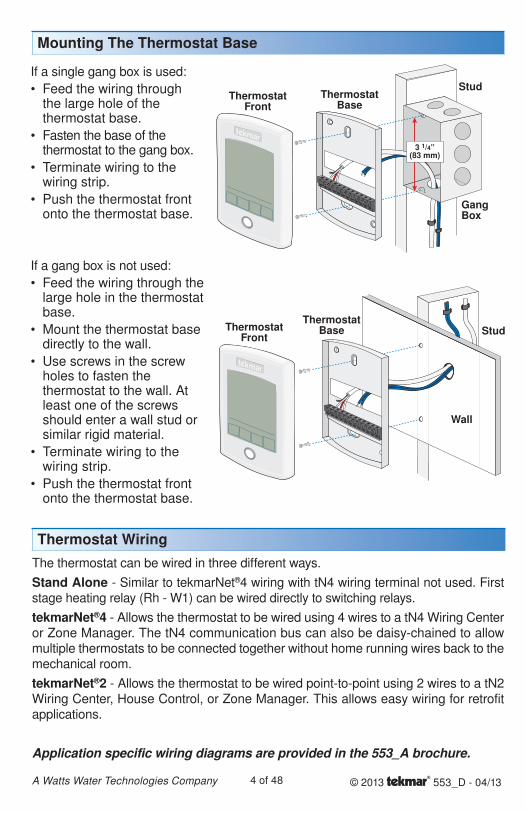
If a gang box is not used:
Feed the wiring through the large hole in the thermostat base.
Mount the thermostat base directly to the wall.
Use screws in the screw holes to fasten the thermostat to the wall. At least one of the screws should enter a wall stud or similar rigid material.
Terminate wiring to the wiring strip.
Push the thermostat front onto the thermostat base.
•
•
•
•
•
Mounting The Thermostat Base
3 1/4”(83 mm)
ThermostatFront
ThermostatBase
Stud
GangBox
If a single gang box is used:
Feed the wiring through the large hole of the thermostat base.
Fasten the base of the thermostat to the gang box.
Terminate wiring to the wiring strip.
Push the thermostat front onto the thermostat base.
•
•
•
•
© 2013 553_D - 04/135 of 48A Watts Water Technologies Company
Testing tekmarNet®2 Wiring ------------------------------------------ ------------------------------------------
Testing the PowerIf the thermostat display turns on, this indicates that the thermostat is operating correctly and there are no electrical issues. In the event that the display is off, or the display is cycling on and off:
1. Remove the thermostat wiring cover.
2. Check to ensure that the tN2 wires on the thermostat are connected to a zone on a House Control, Wiring Center, or Zone Manager.
3. Use an electrical meter to measure DC voltage between the tN2 terminals.
If the DC voltage is 0 V (dc) for at least 20 seconds, then there is an open or short circuit in the tN2 wires.
If the DC voltage is 0 V (dc) for 10 seconds and then is 23 to 24 V (dc) for 5 seconds, this indicates the wiring is correct.
4. If the thermostat display is off, or is cycling on and off, move the thermostat to the next available zone on the House Control, Wiring Center, or Zone Manager.
If the thermostat display remains permanently on, there may be a fault with the previously tried zone on the House Control, Wiring Center, or Zone Manager.
If the thermostat display continues to be off, or is cycling on and off, there may be a fault on the thermostat.
If a fault is suspected, contact your tekmar sales representative for assistance.
Testing tekmarNet®4 and Stand Alone Wiring -------------------------- --------------------------
Testing the Power1. Remove the front cover from the thermostat.
2. Use an electrical test meter to measure (ac) voltage between the R and C terminals. The reading should be 24 V (ac) +/– 10%.
3. Install the front cover.
Testing the Relay Outputs -------------------------------------------- --------------------------------------------
The thermostat includes a User Test to check if the thermostat’s relays are operating and that the thermostat is wired correctly to the HVAC equipment. The User Test setting can be located in the Toolbox menu. Either Heat or Cool test can be selected.
Cancel button - Exits the user test and returns the Toolbox menu.
Hold button - Pauses the user test step for up to 5 minutes.
Next Item button - Advances the user test to the next test step.
•
•
•
•
Testing the Thermostat Wiring
Compatible Sensors
The thermostat is compatible with Indoor Sensor type 076, 077, 084, Slab Sensor type 072, 073, 079, Outdoor Sensor type 070, Universal Sensor 082 and Duct Sensor type 083.
© 2013 553_D - 04/136 of 48A Watts Water Technologies Company
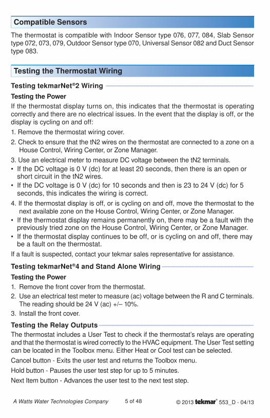
User Test SequenceHeat Test Cool Test
Step Relay(s) Closed Step Relay(s) ClosedO RELAY ON Rc to G/O O RELAY OFF Rc to G/O
B RELAY OFF Rc to G/O B RELAY ON Rc to G/O
FAN ON Rc to G/O (conventional)Rc to ACC (heat pump)
FAN ON Rc to G/O (conventional)Rc to ACC (heat pump)
Y HEAT ON Rc to Y Y COOL ON Rc to Y
W2 HEAT ON Rc to ACC HUMIDIFY ON Rc to ACC
W HEAT Rh to W DEHUMIDIFY ON Rc to ACC
HUMIDIFY ON Rc to ACC(heat and cool)Rc to Y (two-stage heat)
HRV ON Rc to ACC
DEHUMIDIFY ON Rc to ACC
HRV ON Rc to ACC
*availability of test step and additional relay closures based upon Setup menu settings.
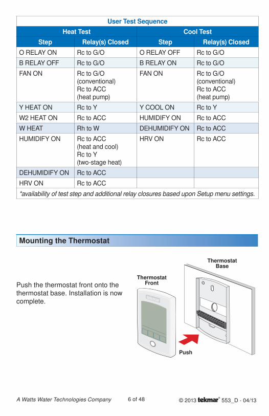
Mounting the Thermostat
Push the thermostat front onto the thermostat base. Installation is now complete.
ThermostatFront
Push
ThermostatBase
© 2013 553_D - 04/137 of 48A Watts Water Technologies Company
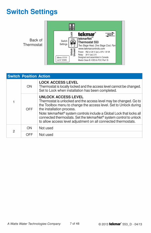
Switch Settings
Switch Position Action
1
ONLOCK ACCESS LEVELThermostat is locally locked and the access level cannot be changed. Set to Lock when installation has been completed.
OFF
UNLOCK ACCESS LEVELThermostat is unlocked and the access level may be changed. Go to the Toolbox menu to change the access level. Set to Unlock during the installation process.Note: tekmarNet® system controls include a Global Lock that locks all connected thermostats. Set the tekmarNet® system control to unlock to allow access level adjustment on all connected thermostats.
2ON Not used
OFF Not used
tekmarNet Thermostat 553Two Stage Heat, One Stage Cool, Fan
Mmm YYYYLot # 12345 Meets Class B: ICES & FCC Part 15
Power: tN2 or 24 V (ac) ±10% 1.8 VARelay: 24 V (ac) 2 A
SwitchSettings
www.tekmarcontrols.com
Designed and assembled in Canada
Lock
Unus
edUn
lock
/
ON
1 2
Back of Thermostat
© 2013 553_D - 04/138 of 48A Watts Water Technologies Company
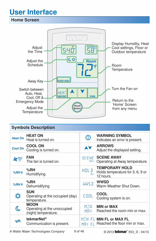
HEAT ONHeat is turned on.
COOL ONCooling is turned on.
FANThe fan is turned on.
%RHHumidifying
%RHDehumidifying
SUNOperating at the occupied (day) temperature.MOONOperating at the unoccupied (night) temperature.
tekmarNet®
Communication is present.
WARNING SYMBOLIndicates an error is present.
ARROWSAdjust the displayed setting.
SCENE AWAYOperating at Away temperature.
TEMPORARY HOLDHolds temperature for 3, 6, 9 or 12 hours.
WWSDWarm Weather Shut Down.
COOLCooling system is on.
MIN or MAXReached the room min or max.
MIN FL or MAX FLReached the floor min or max.
Home Screen
Symbols Description
User Interface
Adjustthe Time
Adjust theSchedule
Display Humidity, Heat Cool settings, Floor or Outdoor temperature
Away Key
Switch betweenAuto, Heat, Cool, Off &
Emergency Mode Return to the ‘Home’ Screen from any menuAdjust the
Temperature
RoomTemperature
Turn the Fan on
HomeButton
© 2013 553_D - 04/139 of 48A Watts Water Technologies Company
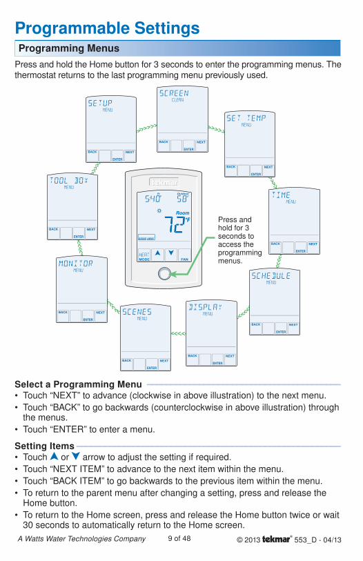
Programmable Settings
Press and hold the Home button for 3 seconds to enter the programming menus. The thermostat returns to the last programming menu previously used.
Programming Menus
Select a Programming Menu ----------------------------------------- -----------------------------------------Touch “NEXT” to advance (clockwise in above illustration) to the next menu.
Touch “BACK” to go backwards (counterclockwise in above illustration) through the menus.
Touch “ENTER” to enter a menu.
Setting Items -------------------------------------------------------- --------------------------------------------------------Touch or arrow to adjust the setting if required.
Touch “NEXT ITEM” to advance to the next item within the menu.
Touch “BACK ITEM” to go backwards to the previous item within the menu.
To return to the parent menu after changing a setting, press and release the Home button.
To return to the Home screen, press and release the Home button twice or wait 30 seconds to automatically return to the Home screen.
•
•
•
•
•
•
•
•
Press and hold for 3 seconds to access the programming menus.
© 2013 553_D - 04/1310 of 48A Watts Water Technologies Company
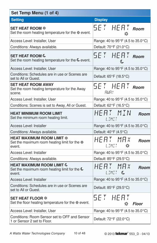
Set Temp Menu (1 of 4)Setting Display
SET HEAT ROOM Set the room heating temperature for the event.
Room
Access Level: Installer, User Range: 40 to 95°F (4.5 to 35.0°C)
Conditions: Always available. Default: 70°F (21.0°C)
SET HEAT ROOM Set the room heating temperature for the event.
Room
Access Level: Installer, User Range: 40 to 95°F (4.5 to 35.0°C)
Conditions: Schedules are in use or Scenes are set to All or Guest.
Default: 65°F (18.5°C)
SET HEAT ROOM AWAYSet the room heating temperature for the Away scene.
Room
Access Level: Installer, User Range: 40 to 95°F (4.5 to 35.0°C)
Conditions: Scenes is set to Away, All or Guest. Default: 62°F (16.5°C)
HEAT MINIMUM ROOM LIMITSet the minimum room heating limit.
Access Level: Installer Range: 40 to 95°F (4.5 to 35.0°C)
Conditions: Always available. Default: 40°F (4.5°C)
HEAT MAXIMUM ROOM LIMIT Set the maximum room heating limit for the event.
Access Level: Installer Range: 40 to 95°F (4.5 to 35.0°C)
Conditions: Always available. Default: 85°F (29.5°C)
HEAT MAXIMUM ROOM LIMIT Set the maximum room heating limit for the event.
Access Level: Installer Range: 40 to 95°F (4.5 to 35.0°C)
Conditions: Schedules are in use or Scenes are set to All or Guest.
Default: 85°F (29.5°C)
SET HEAT FLOOR Set the floor heating temperature for the event. Floor
Access Level: Installer, User Range: 40 to 95°F (4.5 to 35.0°C)
Conditions: Room Sensor set to OFF and Sensor 1 or Sensor 2 set to Floor.
Default: 72°F (22.0°C)
© 2013 553_D - 04/1311 of 48A Watts Water Technologies Company
Setting Display
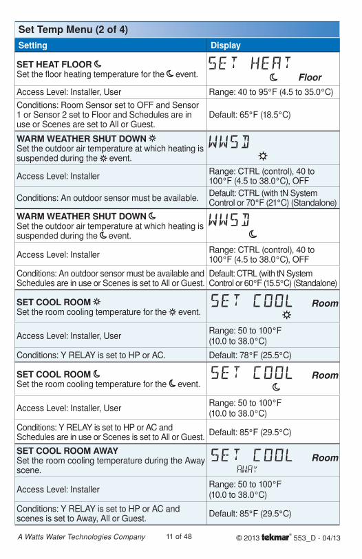
SET HEAT FLOOR Set the floor heating temperature for the event. FloorAccess Level: Installer, User Range: 40 to 95°F (4.5 to 35.0°C)
Conditions: Room Sensor set to OFF and Sensor 1 or Sensor 2 set to Floor and Schedules are in use or Scenes are set to All or Guest.
Default: 65°F (18.5°C)
WARM WEATHER SHUT DOWN Set the outdoor air temperature at which heating is suspended during the event.
Access Level: InstallerRange: CTRL (control), 40 to 100°F (4.5 to 38.0°C), OFF
Conditions: An outdoor sensor must be available.Default: CTRL (with tN System Control or 70°F (21°C) (Standalone)
WARM WEATHER SHUT DOWN Set the outdoor air temperature at which heating is suspended during the event.
Access Level: InstallerRange: CTRL (control), 40 to 100°F (4.5 to 38.0°C), OFF
Conditions: An outdoor sensor must be available and Schedules are in use or Scenes is set to All or Guest.
Default: CTRL (with tN System Control or 60°F (15.5°C) (Standalone)
SET COOL ROOM Set the room cooling temperature for the event.
Access Level: Installer, UserRange: 50 to 100°F (10.0 to 38.0°C)
Conditions: Y RELAY is set to HP or AC. Default: 78°F (25.5°C)
SET COOL ROOM Set the room cooling temperature for the event.
Access Level: Installer, UserRange: 50 to 100°F (10.0 to 38.0°C)
Conditions: Y RELAY is set to HP or AC and Schedules are in use or Scenes is set to All or Guest.
Default: 85°F (29.5°C)
SET COOL ROOM AWAYSet the room cooling temperature during the Away scene.
Access Level: InstallerRange: 50 to 100°F (10.0 to 38.0°C)
Conditions: Y RELAY is set to HP or AC and scenes is set to Away, All or Guest.
Default: 85°F (29.5°C)
Set Temp Menu (2 of 4)
© 2013 553_D - 04/1312 of 48A Watts Water Technologies Company
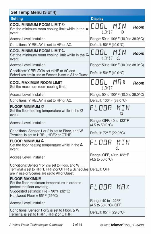
Setting Display
COOL MINIMUM ROOM LIMIT Set the minimum room cooling limit while in the event.
Access Level: Installer Range: 50 to 100°F (10.0 to 38.0°C)
Conditions: Y RELAY is set to HP or AC. Default: 50°F (10.0°C)
COOL MINIMUM ROOM LIMIT Set the minimum room cooling limit while in the event.
Access Level: Installer Range: 50 to 100°F (10.0 to 38.0°C)
Conditions: Y RELAY is set to HP or AC and Schedules are in use or Scenes is set to All or Guest.
Default: 50°F (10.0°C)
COOL MAXIMUM ROOM LIMITSet the maximum room cooling limit.
Access Level: Installer Range: 50 to 100°F (10.0 to 38.0°C)
Conditions: Y RELAY is set to HP or AC. Default: 100°F (38.0°C)
FLOOR MINIMUM Set the floor heating temperature while in the event.
Access Level: InstallerRange: OFF, 40 to 122°F (4.5 to 50.0°C)
Conditions: Sensor 1 or 2 is set to Floor, and W Terminal is set to HRF1, HRF2 or OTHR.
Default: 72°F (22.0°C)
FLOOR MINIMUM Set the floor heating temperature while in the event.
Access Level: InstallerRange: OFF, 40 to 122°F (4.5 to 50.0°C)
Conditions: Sensor 1 or 2 is set to Floor, and W Terminal is set to HRF1, HRF2 or OTHR & Schedules are in use or Scenes are set to All or Guest.
Default: OFF
FLOOR MAXIMUMSet the floor maximum temperature in order to protect the floor covering.Suggested settings: Tile = 90°F (32°C)Hardwood Floor = 85°F (29°C)
Access Level: InstallerRange: 40 to 122°F (4.5 to 50.0°C), OFF
Conditions: Sensor 1 or 2 is set to Floor, & W Terminal is set to HRF1, HRF2 or OTHR.
Default: 85°F (29.5°C)
Set Temp Menu (3 of 4)
© 2013 553_D - 04/1313 of 48A Watts Water Technologies Company
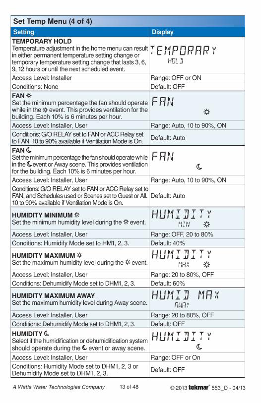
Setting DisplayTEMPORARY HOLDTemperature adjustment in the home menu can result in either permanent temperature setting change or temporary temperature setting change that lasts 3, 6, 9, 12 hours or until the next scheduled event.
Access Level: Installer Range: OFF or ON
Conditions: None Default: OFF
FAN Set the minimum percentage the fan should operate while in the event. This provides ventilation for the building. Each 10% is 6 minutes per hour.
Access Level: Installer, User Range: Auto, 10 to 90%, ON
Conditions: G/O RELAY set to FAN or ACC Relay set to FAN. 10 to 90% available if Ventilation Mode is On.
Default: Auto
FAN Set the minimum percentage the fan should operate while in the event or Away scene. This provides ventilation for the building. Each 10% is 6 minutes per hour.
Access Level: Installer, User Range: Auto, 10 to 90%, ON
Conditions: G/O RELAY set to FAN or ACC Relay set to FAN, and Schedules used or Scenes set to Guest or All. 10 to 90% available if Ventilation Mode is On.
Default: Auto
HUMIDITY MINIMUM Set the minimum humidity level during the event.
Access Level: Installer, User Range: OFF, 20 to 80%
Conditions: Humidify Mode set to HM1, 2, 3. Default: 40%
HUMIDITY MAXIMUM Set the maximum humidity level during the event.
Access Level: Installer, User Range: 20 to 80%, OFF
Conditions: Dehumidify Mode set to DHM1, 2, 3. Default: 60%
HUMIDITY MAXIMUM AWAYSet the maximum humidity level during Away scene.
Access Level: Installer, User Range: 20 to 80%, OFF
Conditions: Dehumidify Mode set to DHM1, 2, 3. Default: OFF
HUMIDITY Select if the humidification or dehumidification system should operate during the event or away scene.
Access Level: Installer, User Range: OFF or On
Conditions: Humidity Mode set to DHM1, 2, 3 or Dehumidify Mode set to DHM1, 2, 3.
Default: OFF
Set Temp Menu (4 of 4)
© 2013 553_D - 04/1314 of 48A Watts Water Technologies Company
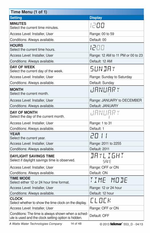
Time Menu (1 of 1)Setting Display
MINUTESSelect the current time minutes.
Access Level: Installer, User Range: 00 to 59
Conditions: Always available. Default: 00
HOURSSelect the current time hours.
Access Level: Installer, User Range: 12 AM to 11 PM or 00 to 23
Conditions: Always available. Default: 12 AM
DAY OF WEEKSelect the current day of the week.
Access Level: Installer, User Range: Sunday to Saturday
Conditions: Always available. Default: Sunday
MONTHSelect the current month.
Access Level: Installer, User Range: JANUARY to DECEMBER
Conditions: Always available. Default: JANUARY
DAY OF MONTHSelect the day of the current month.
Access Level: Installer, User Range: 1 to 31
Conditions: Always available. Default: 1
YEARSelect the current year.
Access Level: Installer, User Range: 2011 to 2255
Conditions: Always available. Default: 2011
DAYLIGHT SAVINGS TIMESelect if daylight savings time is observed.
Access Level: Installer, User Range: OFF or ON
Conditions: Always available. Default: ON
TIME MODESelect either 12 or 24 hour time format.
Access Level: Installer, User Range: 12 or 24 hour
Conditions: Always available. Default: 12 hour
CLOCKSelect whether to show the time clock on the display.
Access Level: Installer, User Range: OFF or ON
Conditions: The time is always shown when a sched-ule is used and the clock setting option is hidden.
Default: OFF
© 2013 553_D - 04/1315 of 48A Watts Water Technologies Company
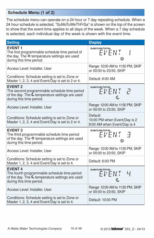
Schedule Menu (1 of 2)
Setting DisplayEVENT 1The first programmable schedule time period of the day. The temperature settings are used during this time period.
SuMoTuWeThFrSa
Access Level: Installer, UserRange: 12:00 AM to 11:50 PM, SKIP or 00:00 to 23:50, SKIP
Conditions: Schedule setting is set to Zone or Master 1, 2, 3, 4 and Event/Day is set to 2 or 4.
Default: 6:00 AM
EVENT 2The second programmable schedule time period of the day. The temperature settings are used during this time period.
SuMoTuWeThFrSa
Access Level: Installer, UserRange: 12:00 AM to 11:50 PM, SKIPor 00:00 to 23:50, SKIP
Conditions: Schedule setting is set to Zone or Master 1, 2, 3, 4 and Event/Day is set to 2 or 4.
Default:10:00 PM when Event/Day is 2 8:00 AM when Event/Day is 4
EVENT 3The third programmable schedule time period of the day. The temperature settings are used during this time period.
SuMoTuWeThFrSa
Access Level: Installer, UserRange: 12:00 AM to 11:50 PM, SKIPor 00:00 to 23:50, SKIP
Conditions: Schedule setting is set to Zone or Master 1, 2, 3, 4 and Event/Day is set to 4.
Default: 6:00 PM
EVENT 4The fourth programmable schedule time period of the day. The temperature settings are used during this time period.
SuMoTuWeThFrSa
Access Level: Installer, UserRange: 12:00 AM to 11:50 PM, SKIPor 00:00 to 23:50, SKIP
Conditions: Schedule setting is set to Zone or Master 1, 2, 3, 4 and Event/Day is set to 4.
Default: 10:00 PM
The schedule menu can operate on a 24 hour or 7 day repeating schedule. When a 24 hour schedule is selected, “SuMoTuWeThFrSa” is shown on the top of the screen to show that the event time applies to all days of the week. When a 7 day schedule is selected, each individual day of the week is shown with the event time.
© 2013 553_D - 04/1316 of 48A Watts Water Technologies Company
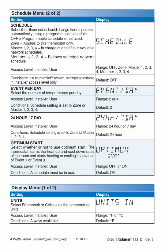
Setting DisplaySCHEDULESelect if the thermostat should change the temperature automatically using a programmable schedule.OFF = Programmable schedule is not used.Zone = Applies to this thermostat only.Master 1, 2, 3, 4 = In charge of one of four available network schedules.Member 1, 2, 3, 4 = Follows selected network schedule.
Access Level: Installer, UserRange: OFF, Zone, Master 1, 2, 3, 4, Member 1, 2, 3, 4
Conditions: In a tekmarNet® system, settings adjustable in Installer access level only.
Default: OFF
EVENT PER DAYSelect the number of temperatures per day.
Access Level: Installer, User Range: 2 or 4
Conditions: Schedule setting is set to Zone or Master 1, 2, 3, 4.
Default: 2
24 HOUR / 7 DAY
Access Level: Installer, User Range: 24 hour or 7 day
Conditions: Schedule setting is set to Zone or Master 1, 2, 3, 4.
Default: 24 hour
OPTIMUM STARTSelect whether or not to use optimum start. The thermostat learns the heat up and cool down rates of the room and starts heating or cooling in advance of Event 1 or Event 3.
Access Level: Installer, User Range: OFF or ON
Conditions: A schedule must be in use. Default: ON
Schedule Menu (2 of 2)
Display Menu (1 of 2)Setting DisplayUNITSSelect Fahrenheit or Celsius as the temperature units.
Access Level: Installer, User Range: °F or °C
Conditions: Always available. Default: °F
© 2013 553_D - 04/1317 of 48A Watts Water Technologies Company
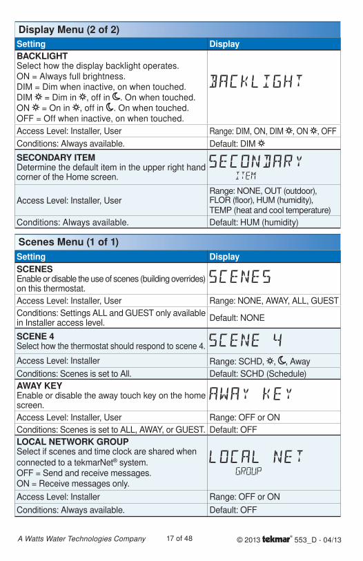
Scenes Menu (1 of 1)Setting DisplaySCENESEnable or disable the use of scenes (building overrides) on this thermostat.
Access Level: Installer, User Range: NONE, AWAY, ALL, GUEST
Conditions: Settings ALL and GUEST only available in Installer access level.
Default: NONE
SCENE 4Select how the thermostat should respond to scene 4.
Access Level: Installer Range: SCHD, , , Away
Conditions: Scenes is set to All. Default: SCHD (Schedule)
AWAY KEYEnable or disable the away touch key on the home screen.
Access Level: Installer, User Range: OFF or ON
Conditions: Scenes is set to ALL, AWAY, or GUEST. Default: OFF
LOCAL NETWORK GROUPSelect if scenes and time clock are shared when
connected to a tekmarNet® system.OFF = Send and receive messages.ON = Receive messages only.
Access Level: Installer Range: OFF or ON
Conditions: Always available. Default: OFF
Display Menu (2 of 2)Setting DisplayBACKLIGHTSelect how the display backlight operates.ON = Always full brightness.DIM = Dim when inactive, on when touched.DIM = Dim in , off in . On when touched.ON = On in , off in . On when touched.OFF = Off when inactive, on when touched.
Access Level: Installer, User Range: DIM, ON, DIM , ON , OFF
Conditions: Always available. Default: DIM
SECONDARY ITEMDetermine the default item in the upper right hand corner of the Home screen.
Access Level: Installer, UserRange: NONE, OUT (outdoor), FLOR (floor), HUM (humidity),TEMP (heat and cool temperature)
Conditions: Always available. Default: HUM (humidity)
© 2013 553_D - 04/1318 of 48A Watts Water Technologies Company
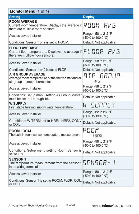
Monitor Menu (1 of 4)Setting DisplayROOM AVERAGECurrent room temperature. Displays the average if there are multiple room sensors.
Access Level: InstallerRange: -58 to 212°F (-50.0 to 100.0°C)
Conditions: Sensor 1 or 2 is set to ROOM. Default: Not applicable.
FLOOR AVERAGECurrent floor temperature. Displays the average if there are multiple floor sensors.
Access Level: InstallerRange: -58 to 212°F (-50.0 to 100.0°C)
Conditions: Sensor 1 or 2 is set to FLOR. Default: Not applicable.
AIR GROUP AVERAGEAverage room temperature of the thermostat and all air group member thermostats.
Access Level: InstallerRange: -58 to 212°F (-50.0 to 100.0°C)
Conditions: Setup menu setting Air Group Master must be set to 1 through 16.
Default: Not applicable.
W SUPPLYFirst stage heating supply water temperature.
Access Level: InstallerRange: -22 to 266°F (-30.0 to 130.0°C)
Conditions: W TERM set to HRF1, HRF2, CONV or COIL.
Default: Not applicable.
ROOM LOCALThe built-in room sensor temperature measurement.
Access Level: InstallerRange: -58 to 212°F (-50.0 to 100.0°C)
Conditions: Setup menu setting Room Sensor is set to ON.
Default: Not applicable.
SENSOR 1The temperature measurement from the sensor 1 input wiring terminals.
Access Level: InstallerRange: -58 to 212°F (-50.0 to 100.0°C)
Conditions: Sensor 1 is set to ROOM, FLOR, COIL or DUCT.
Default: Not applicable.
© 2013 553_D - 04/1319 of 48A Watts Water Technologies Company
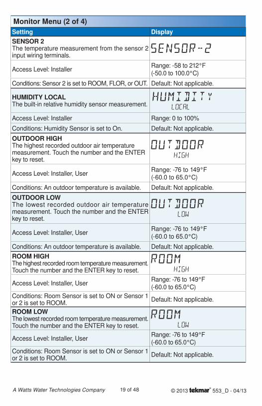
Setting DisplaySENSOR 2The temperature measurement from the sensor 2 input wiring terminals.
Access Level: InstallerRange: -58 to 212°F (-50.0 to 100.0°C)
Conditions: Sensor 2 is set to ROOM, FLOR, or OUT. Default: Not applicable.
HUMIDITY LOCALThe built-in relative humidity sensor measurement.
Access Level: Installer Range: 0 to 100%
Conditions: Humidity Sensor is set to On. Default: Not applicable.
OUTDOOR HIGHThe highest recorded outdoor air temperature measurement. Touch the number and the ENTER key to reset.
Access Level: Installer, UserRange: -76 to 149°F(-60.0 to 65.0°C)
Conditions: An outdoor temperature is available. Default: Not applicable.
OUTDOOR LOWThe lowest recorded outdoor air temperature measurement. Touch the number and the ENTER key to reset.
Access Level: Installer, UserRange: -76 to 149°F (-60.0 to 65.0°C)
Conditions: An outdoor temperature is available. Default: Not applicable.
ROOM HIGHThe highest recorded room temperature measurement. Touch the number and the ENTER key to reset.
Access Level: Installer, UserRange: -76 to 149°F (-60.0 to 65.0°C)
Conditions: Room Sensor is set to ON or Sensor 1 or 2 is set to ROOM.
Default: Not applicable.
ROOM LOWThe lowest recorded room temperature measurement. Touch the number and the ENTER key to reset.
Access Level: Installer, UserRange: -76 to 149°F (-60.0 to 65.0°C)
Conditions: Room Sensor is set to ON or Sensor 1 or 2 is set to ROOM.
Default: Not applicable.
Monitor Menu (2 of 4)
© 2013 553_D - 04/1320 of 48A Watts Water Technologies Company
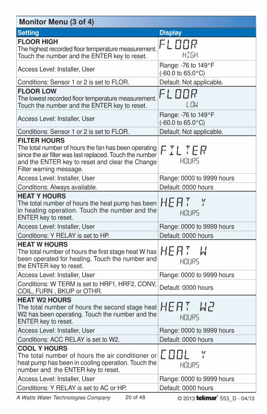
Setting DisplayFLOOR HIGHThe highest recorded floor temperature measurement. Touch the number and the ENTER key to reset.
Access Level: Installer, UserRange: -76 to 149°F (-60.0 to 65.0°C)
Conditions: Sensor 1 or 2 is set to FLOR. Default: Not applicable.
FLOOR LOWThe lowest recorded floor temperature measurement. Touch the number and the ENTER key to reset.
Access Level: Installer, UserRange: -76 to 149°F (-60.0 to 65.0°C)
Conditions: Sensor 1 or 2 is set to FLOR. Default: Not applicable.
FILTER HOURSThe total number of hours the fan has been operating since the air filter was last replaced. Touch the number and the ENTER key to reset and clear the Change Filter warning message.
Access Level: Installer, User Range: 0000 to 9999 hours
Conditions: Always available. Default: 0000 hours
HEAT Y HOURSThe total number of hours the heat pump has been in heating operation. Touch the number and the ENTER key to reset.
Access Level: Installer, User Range: 0000 to 9999 hours
Conditions: Y RELAY is set to HP. Default: 0000 hours
HEAT W HOURSThe total number of hours the first stage heat W has been operated for heating. Touch the number and the ENTER key to reset.
Access Level: Installer, User Range: 0000 to 9999 hours
Conditions: W TERM is set to HRF1, HRF2, CONV, COIL, FURN , BKUP or OTHR.
Default: 0000 hours
HEAT W2 HOURSThe total number of hours the second stage heat W2 has been operating. Touch the number and the ENTER key to reset.
Access Level: Installer, User Range: 0000 to 9999 hours
Conditions: ACC RELAY is set to W2. Default: 0000 hours
COOL Y HOURSThe total number of hours the air conditioner or heat pump has been in cooling operation. Touch the number and the ENTER key to reset.
Access Level: Installer, User Range: 0000 to 9999 hours
Conditions: Y RELAY is set to AC or HP. Default: 0000 hours
Monitor Menu (3 of 4)
© 2013 553_D - 04/1321 of 48A Watts Water Technologies Company
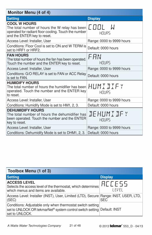
Setting DisplayCOOL W HOURSThe total number of hours the W relay has been operated for radiant floor cooling. Touch the number and the ENTER key to reset.
Access Level: Installer, User Range: 0000 to 9999 hours
Conditions: Floor Cool is set to ON and W TERM is set to HRF1 or HRF2.
Default: 0000 hours
FAN HOURSThe total number of hours the fan has been operated. Touch the number and the ENTER key to reset.
Access Level: Installer, User Range: 0000 to 9999 hours
Conditions: G/O RELAY is set to FAN or ACC Relay is set to FAN.
Default: 0000 hours
HUMIDIFY HOURSThe total number of hours the humidifier has been operated. Touch the number and the ENTER key to reset.
Access Level: Installer, User Range: 0000 to 9999 hours
Conditions: Humidify Mode is set to HM1, 2, 3. Default: 0000 hours
DEHUMIDIFY HOURSThe total number of hours the dehumidifier has been operated. Touch the number and the ENTER key to reset.
Access Level: Installer, User Range: 0000 to 9999 hours
Conditions: Dehumidify Mode is set to DHM1, 2, 3. Default: 0000 hours
Monitor Menu (4 of 4)
Setting DisplayACCESS LEVELSelects the access level of the thermostat, which determines which menus and items are available.
Access Level: Installer (INST), User, Limited (LTD), Secure (SEC)
Range: INST, USER, LTD, SEC
Conditions: Adjustable only when thermostat switch setting
set to UNLOCK OR tekmarNet® system control switch setting set to UNLOCK.
Default: INST
Toolbox Menu (1 of 3)
© 2013 553_D - 04/1322 of 48A Watts Water Technologies Company
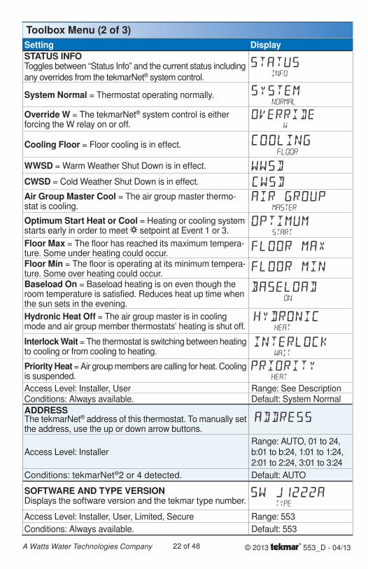
Setting DisplaySTATUS INFOToggles between “Status Info” and the current status including
any overrides from the tekmarNet® system control.
System Normal = Thermostat operating normally.
Override W = The tekmarNet® system control is either forcing the W relay on or off.
Cooling Floor = Floor cooling is in effect.
WWSD = Warm Weather Shut Down is in effect.
CWSD = Cold Weather Shut Down is in effect.
Air Group Master Cool = The air group master thermo-stat is cooling.
Optimum Start Heat or Cool = Heating or cooling system starts early in order to meet setpoint at Event 1 or 3.
Floor Max = The floor has reached its maximum tempera-ture. Some under heating could occur.Floor Min = The floor is operating at its minimum tempera-ture. Some over heating could occur.Baseload On = Baseload heating is on even though the room temperature is satisfied. Reduces heat up time when the sun sets in the evening.
Hydronic Heat Off = The air group master is in cooling mode and air group member thermostats’ heating is shut off.
Interlock Wait = The thermostat is switching between heating to cooling or from cooling to heating.
Priority Heat = Air group members are calling for heat. Cooling is suspended.
Access Level: Installer, User Range: See DescriptionConditions: Always available. Default: System Normal
ADDRESSThe tekmarNet® address of this thermostat. To manually set the address, use the up or down arrow buttons.
Access Level: InstallerRange: AUTO, 01 to 24, b:01 to b:24, 1:01 to 1:24, 2:01 to 2:24, 3:01 to 3:24
Conditions: tekmarNet®2 or 4 detected. Default: AUTO
SOFTWARE AND TYPE VERSIONDisplays the software version and the tekmar type number.
Access Level: Installer, User, Limited, Secure Range: 553
Conditions: Always available. Default: 553
Toolbox Menu (2 of 3)
© 2013 553_D - 04/1323 of 48A Watts Water Technologies Company
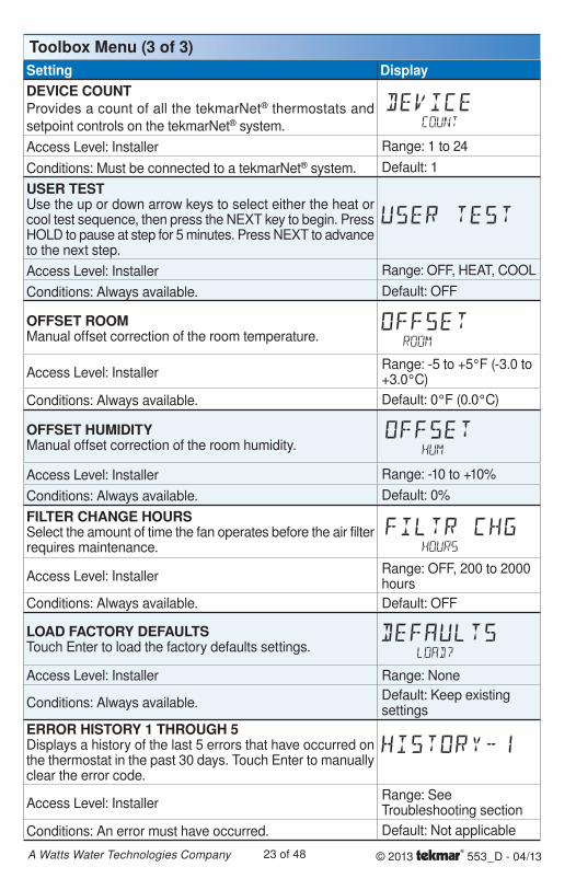
Toolbox Menu (3 of 3)Setting DisplayDEVICE COUNTProvides a count of all the tekmarNet® thermostats and
setpoint controls on the tekmarNet® system.
Access Level: Installer Range: 1 to 24
Conditions: Must be connected to a tekmarNet® system. Default: 1
USER TESTUse the up or down arrow keys to select either the heat or cool test sequence, then press the NEXT key to begin. Press HOLD to pause at step for 5 minutes. Press NEXT to advance to the next step.
Access Level: Installer Range: OFF, HEAT, COOL
Conditions: Always available. Default: OFF
OFFSET ROOMManual offset correction of the room temperature.
Access Level: InstallerRange: -5 to +5°F (-3.0 to +3.0°C)
Conditions: Always available. Default: 0°F (0.0°C)
OFFSET HUMIDITYManual offset correction of the room humidity.
Access Level: Installer Range: -10 to +10%
Conditions: Always available. Default: 0%
FILTER CHANGE HOURSSelect the amount of time the fan operates before the air filter requires maintenance.
Access Level: InstallerRange: OFF, 200 to 2000 hours
Conditions: Always available. Default: OFF
LOAD FACTORY DEFAULTSTouch Enter to load the factory defaults settings.
Access Level: Installer Range: None
Conditions: Always available.Default: Keep existing settings
ERROR HISTORY 1 THROUGH 5Displays a history of the last 5 errors that have occurred on the thermostat in the past 30 days. Touch Enter to manually clear the error code.
Access Level: InstallerRange: See Troubleshooting section
Conditions: An error must have occurred. Default: Not applicable
© 2013 553_D - 04/1324 of 48A Watts Water Technologies Company
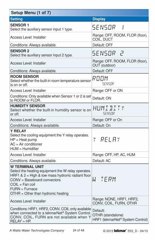
Setup Menu (1 of 7)Setting Display
SENSOR 1Select the auxiliary sensor input 1 type.
Access Level: InstallerRange: OFF, ROOM, FLOR (floor), COIL, DUCT
Conditions: Always available. Default: OFF
SENSOR 2Select the auxiliary sensor input 2 type.
Access Level: InstallerRange: OFF, ROOM, FLOR (floor), OUT (outdoor)
Conditions: Always available. Default: OFF
ROOM SENSORSelect whether the built-in room temperature sensor is on or off.
Access Level: Installer Range: OFF or ON
Conditions: Only available when Sensor 1 or 2 is set to ROOM or FLOR.
Default: ON
HUMIDITY SENSORSelect whether the built-in humidity sensor is on or off.
Access Level: Installer Range: OFF or On
Conditions: Always available. Default: On
Y RELAYSelect the cooling equipment the Y relay operates.HP = Heat pump AC = Air conditioner HUM = Humidifier
Access Level: Installer Range: OFF, HP, AC, HUM
Conditions: Always available. Default: AC
W TERMINAL UNITSelect the heating equipment the W relay operates.HRF1 & 2 = High & low mass hydronic radiant floorCONV = Baseboard convectorsCOIL = Fan coilFURN = FurnaceOTHR = Other than hydronic heating
Access Level: InstallerRange: NONE, HRF1, HRF2, CONV, COIL, FURN, OTHR
Conditions: HRF1, HRF2, CONV, COIL only available when connected to a tekmarNet® System Control. CONV, COIL, FURN are not available when Y RELAY = HP.
Default:OTHR (standalone)HRF1 (tekmarNet® System Control)
© 2013 553_D - 04/1325 of 48A Watts Water Technologies Company
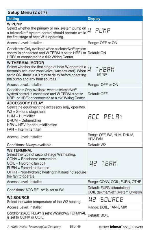
Setting DisplayW PUMPSelect whether the primary or mix system pump on
a tekmarNet® system control should operate while the first stage of heat W is operating.
Access Level: Installer Range: OFF or ON
Conditions: Only available when a tekmarNet® system control is connected and W TERM is set to HRF1 or HRF2 or connected to a tN2 Wiring Center.
Default: ON
W THERMAL MOTORSelect whether the first stage of heat W operates a thermally actuated zone valve (wax actuator). When set to ON, there is a 3 minute delay before operating the pump and any heat sources.
Access Level: Installer Range: OFF or ON
Conditions: Only available when a tekmarNet® system control is connected and W TERM is set to HRF1 or HRF2 or connected to a tN2 Wiring Center.
Default: OFF
ACCESSORY RELAYSelect the equipment the accessory relay operates.W2 = Second stage heatHUM = HumidifierDHUM = DehumidifierHRV = HRV for dehumidificationFAN = Intermittent fan
Access Level: InstallerRange: OFF, W2, HUM, DHUM, HRV, FAN
Conditions: Always available. Default: W2
W2 TERMINALSelect the type of second stage W2 heating.CONV = Baseboard convectorsCOIL = Hydronic fan coilFURN = Forced air furnaceOTHR = Non-hydronic heating that does not require the fan to operate
Access Level: Installer Range: CONV, COIL, FURN, OTHR
Conditions: ACC RELAY is set to W2.Default: FURN (standalone)COIL (tekmarNet® System Control)
W2 SOURCESelect the water temperature of the W2 heating.
Access Level: Installer Range: BOIL, TANK, MIX
Conditions: ACC RELAY is set to W2 and W2 TERMINAL is set to CONV or COIL.
Default: BOIL
Setup Menu (2 of 7)
© 2013 553_D - 04/1326 of 48A Watts Water Technologies Company
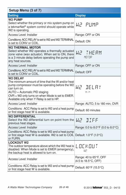
Setup Menu (3 of 7)Setting DisplayW2 PUMPSelect whether the primary or mix system pump on
a tekmarNet® system control should operate while W2 is operating.
Access Level: Installer Range: OFF or ON
Conditions: ACC RELAY is set to W2 and W2 TERMINAL is set to CONV or COIL.
Default: ON
W2 THERMAL MOTORSelect whether W2 operates a thermally actuated zone valve (wax actuator). When set to ON, there is a 3 minute delay before operating the pump and any heat sources.
Access Level: Installer Range: OFF or ON
Conditions: ACC RELAY is set to W2 and W2 TERMINAL is set to CONV or COIL.
Default: OFF
W2 DELAYThe minimum amount of time that the W and/or heat pump compressor must be operating before the W2 can turn on.AUTO = Automatic PID stagingOVR = W2 only turns on when Mode is set to EMER. Available only when Y Relay is set to HP.
Access Level: Installer Range: AUTO, 5 to 180 min, OVR
Conditions: ACC Relay is set to W2 and a heat pump or first stage heat W is available.
Default: 60 minutes
W2 DIFFERENTIALSelect the W2 differential turn on point from the previous heat stages.
Access Level: Installer Range: 0.0 to 8.0°F (0.0 to 8.0°C)
Conditions: ACC Relay is set to W2 and a heat pump or first stage heat W is available. W2 is set to COIL or FURN.
Default: 1.0°F (1.0°C)
LOCKOUT W2The outdoor temperature above which the W2 heat is disabled. When Mode is set to EMER (emergency), the backup heat is allowed to turn on.
Access Level: InstallerRange: 40 to 65°F, OFF (4.5 to 18.5°C, OFF)
Conditions: ACC Relay is set to W2 and a heat pump or first stage heat W is available.
Default: 60°F (15.5°C)
© 2013 553_D - 04/1327 of 48A Watts Water Technologies Company
Setup Menu (4 of 7)Setting Display
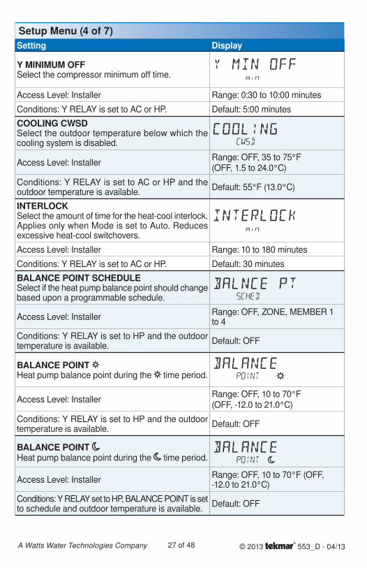
Y MINIMUM OFFSelect the compressor minimum off time.
Access Level: Installer Range: 0:30 to 10:00 minutes
Conditions: Y RELAY is set to AC or HP. Default: 5:00 minutes
COOLING CWSDSelect the outdoor temperature below which the cooling system is disabled.
Access Level: InstallerRange: OFF, 35 to 75°F (OFF, 1.5 to 24.0°C)
Conditions: Y RELAY is set to AC or HP and the outdoor temperature is available.
Default: 55°F (13.0°C)
INTERLOCKSelect the amount of time for the heat-cool interlock. Applies only when Mode is set to Auto. Reduces excessive heat-cool switchovers.
Access Level: Installer Range: 10 to 180 minutes
Conditions: Y RELAY is set to AC or HP. Default: 30 minutes
BALANCE POINT SCHEDULESelect if the heat pump balance point should change based upon a programmable schedule.
Access Level: InstallerRange: OFF, ZONE, MEMBER 1 to 4
Conditions: Y RELAY is set to HP and the outdoor temperature is available.
Default: OFF
BALANCE POINT Heat pump balance point during the time period.
Access Level: InstallerRange: OFF, 10 to 70°F (OFF, -12.0 to 21.0°C)
Conditions: Y RELAY is set to HP and the outdoor temperature is available.
Default: OFF
BALANCE POINT Heat pump balance point during the time period.
Access Level: InstallerRange: OFF, 10 to 70°F (OFF, -12.0 to 21.0°C)
Conditions: Y RELAY set to HP, BALANCE POINT is set to schedule and outdoor temperature is available.
Default: OFF
© 2013 553_D - 04/1328 of 48A Watts Water Technologies Company
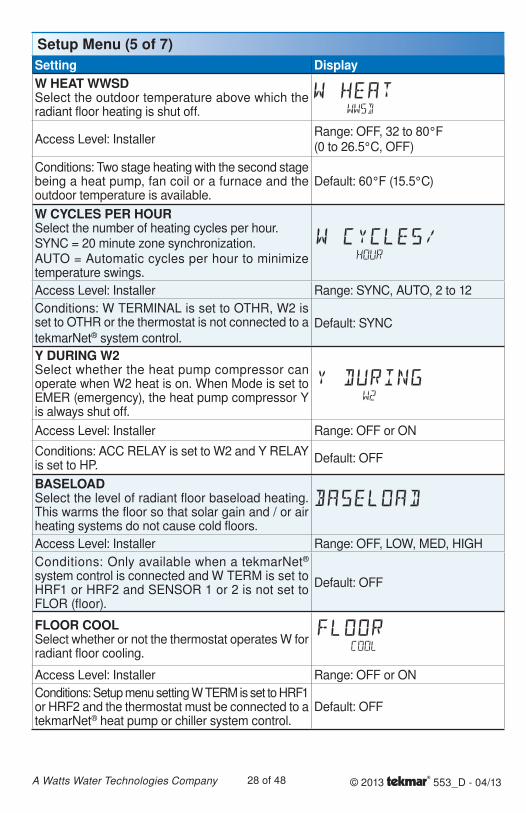
Setup Menu (5 of 7)Setting DisplayW HEAT WWSDSelect the outdoor temperature above which the radiant floor heating is shut off.
Access Level: InstallerRange: OFF, 32 to 80°F (0 to 26.5°C, OFF)
Conditions: Two stage heating with the second stage being a heat pump, fan coil or a furnace and the outdoor temperature is available.
Default: 60°F (15.5°C)
W CYCLES PER HOURSelect the number of heating cycles per hour.SYNC = 20 minute zone synchronization.AUTO = Automatic cycles per hour to minimize temperature swings.
Access Level: Installer Range: SYNC, AUTO, 2 to 12
Conditions: W TERMINAL is set to OTHR, W2 is set to OTHR or the thermostat is not connected to a
tekmarNet® system control.Default: SYNC
Y DURING W2Select whether the heat pump compressor can operate when W2 heat is on. When Mode is set to EMER (emergency), the heat pump compressor Y is always shut off.
Access Level: Installer Range: OFF or ON
Conditions: ACC RELAY is set to W2 and Y RELAY is set to HP.
Default: OFF
BASELOADSelect the level of radiant floor baseload heating. This warms the floor so that solar gain and / or air heating systems do not cause cold floors.
Access Level: Installer Range: OFF, LOW, MED, HIGH
Conditions: Only available when a tekmarNet® system control is connected and W TERM is set to HRF1 or HRF2 and SENSOR 1 or 2 is not set to FLOR (floor).
Default: OFF
FLOOR COOLSelect whether or not the thermostat operates W for radiant floor cooling.
Access Level: Installer Range: OFF or ON
Conditions: Setup menu setting W TERM is set to HRF1 or HRF2 and the thermostat must be connected to a tekmarNet® heat pump or chiller system control.
Default: OFF
© 2013 553_D - 04/1329 of 48A Watts Water Technologies Company
Setup Menu (6 of 7)Setting Display
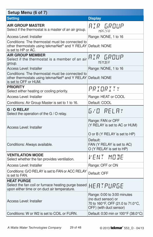
AIR GROUP MASTERSelect if the thermostat is a master of an air group.
Access Level: Installer Range: NONE, 1 to 16
Conditions: The thermostat must be connected to other thermostats using tekmarNet® and Y RELAY is set to HP or AC.
Default: NONE
AIR GROUP MEMBERSelect if the thermostat is a member of an air group.
Access Level: Installer Range: NONE, 1 to 16
Conditions: The thermostat must be connected to other thermostats using tekmarNet® and Y RELAY is set to OFF or HUM.
Default: NONE
PRIORITYSelect either heating or cooling priority.
Access Level: Installer Range: HEAT or COOL
Conditions: Air Group Master is set to 1 to 16. Default: COOL
G / O RELAYSelect the operation of the G / O relay.
Access Level: Installer
Range: FAN or OFF (Y RELAY is set to AC or HUM)
O or B (Y RELAY is set to HP)
Conditions: Always available.Default: FAN (Y RELAY is set to AC)O (Y RELAY is set to HP)
VENTILATION MODESelect whether the fan provides ventilation.
Access Level: Installer Range: OFF or ON
Conditions: G/O RELAY is set to FAN or ACC RELAY is set to FAN.
Default: OFF
HEAT PURGESelect the fan coil or furnace heating purge based upon either time or on duct air temperature.
Access Level: Installer
Range: 0:00 to 3:00 minutes(no duct sensor) or70 to 160°F, OFF (21.0 to 71.0°C, OFF) (with duct sensor)
Conditions: W or W2 is set to COIL or FURN. Default: 0:30 min or 100°F (38.0°C)
© 2013 553_D - 04/1330 of 48A Watts Water Technologies Company
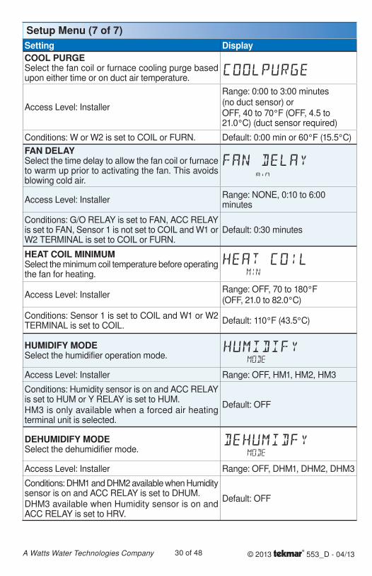
Setup Menu (7 of 7)Setting DisplayCOOL PURGESelect the fan coil or furnace cooling purge based upon either time or on duct air temperature.
Access Level: Installer
Range: 0:00 to 3:00 minutes(no duct sensor) orOFF, 40 to 70°F (OFF, 4.5 to 21.0°C) (duct sensor required)
Conditions: W or W2 is set to COIL or FURN. Default: 0:00 min or 60°F (15.5°C)
FAN DELAYSelect the time delay to allow the fan coil or furnace to warm up prior to activating the fan. This avoids blowing cold air.
Access Level: InstallerRange: NONE, 0:10 to 6:00 minutes
Conditions: G/O RELAY is set to FAN, ACC RELAY is set to FAN, Sensor 1 is not set to COIL and W1 or W2 TERMINAL is set to COIL or FURN.
Default: 0:30 minutes
HEAT COIL MINIMUMSelect the minimum coil temperature before operating the fan for heating.
Access Level: InstallerRange: OFF, 70 to 180°F (OFF, 21.0 to 82.0°C)
Conditions: Sensor 1 is set to COIL and W1 or W2 TERMINAL is set to COIL.
Default: 110°F (43.5°C)
HUMIDIFY MODESelect the humidifier operation mode.
Access Level: Installer Range: OFF, HM1, HM2, HM3
Conditions: Humidity sensor is on and ACC RELAY is set to HUM or Y RELAY is set to HUM.HM3 is only available when a forced air heating terminal unit is selected.
Default: OFF
DEHUMIDIFY MODESelect the dehumidifier mode.
Access Level: Installer Range: OFF, DHM1, DHM2, DHM3
Conditions: DHM1 and DHM2 available when Humidity sensor is on and ACC RELAY is set to DHUM.DHM3 available when Humidity sensor is on and ACC RELAY is set to HRV.
Default: OFF
© 2013 553_D - 04/1331 of 48A Watts Water Technologies Company
Sequence of OperationHeat and Cool Applications Section A
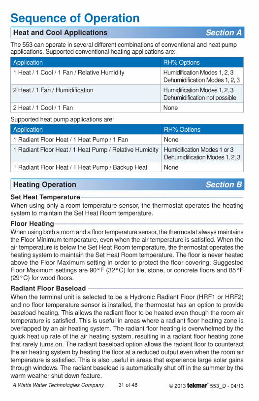
The 553 can operate in several different combinations of conventional and heat pump applications. Supported conventional heating applications are:
Application RH% Options
1 Heat / 1 Cool / 1 Fan / Relative Humidity Humidification Modes 1, 2, 3 Dehumidification Modes 1, 2, 3
2 Heat / 1 Fan / Humidification Humidification Modes 1, 2, 3 Dehumidification not possible
2 Heat / 1 Cool / 1 Fan None
Supported heat pump applications are:
Application RH% Options
1 Radiant Floor Heat / 1 Heat Pump / 1 Fan None
1 Radiant Floor Heat / 1 Heat Pump / Relative Humidity Humidification Modes 1 or 3 Dehumidification Modes 1, 2, 3
1 Radiant Floor Heat / 1 Heat Pump / Backup Heat None
Heating Operation Section BSet Heat Temperature ------------------------------------------------ ------------------------------------------------When using only a room temperature sensor, the thermostat operates the heating system to maintain the Set Heat Room temperature.
Floor Heating -------------------------------------------------------- --------------------------------------------------------When using both a room and a floor temperature sensor, the thermostat always maintains the Floor Minimum temperature, even when the air temperature is satisfied. When the air temperature is below the Set Heat Room temperature, the thermostat operates the heating system to maintain the Set Heat Room temperature. The floor is never heated above the Floor Maximum setting in order to protect the floor covering. Suggested Floor Maximum settings are 90°F (32°C) for tile, stone, or concrete floors and 85°F (29°C) for wood floors.
Radiant Floor Baseload ---------------------------------------------- ----------------------------------------------When the terminal unit is selected to be a Hydronic Radiant Floor (HRF1 or HRF2)
and no floor temperature sensor is installed, the thermostat has an option to provide
baseload heating. This allows the radiant floor to be heated even though the room air
temperature is satisfied. This is useful in areas where a radiant floor heating zone is
overlapped by an air heating system. The radiant floor heating is overwhelmed by the
quick heat up rate of the air heating system, resulting in a radiant floor heating zone
that rarely turns on. The radiant baseload option allows the radiant floor to counteract
the air heating system by heating the floor at a reduced output even when the room air
temperature is satisfied. This is also useful in areas that experience large solar gains
through windows. The radiant baseload is automatically shut off in the summer by the
warm weather shut down feature.
© 2013 553_D - 04/1332 of 48A Watts Water Technologies Company
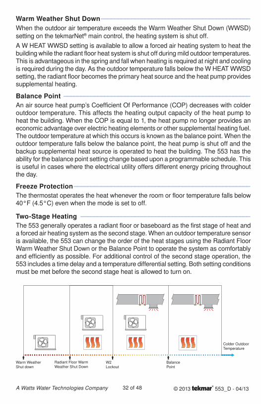
Warm Weather Shut Down -------------------------------------------- --------------------------------------------
When the outdoor air temperature exceeds the Warm Weather Shut Down (WWSD)
setting on the tekmarNet® main control, the heating system is shut off.
A W HEAT WWSD setting is available to allow a forced air heating system to heat the building while the radiant floor heat system is shut off during mild outdoor temperatures. This is advantageous in the spring and fall when heating is required at night and cooling is required during the day. As the outdoor temperature falls below the W HEAT WWSD setting, the radiant floor becomes the primary heat source and the heat pump provides supplemental heating.
Balance Point ------------------------------------------------------- -------------------------------------------------------
An air source heat pump’s Coefficient Of Performance (COP) decreases with colder outdoor temperature. This affects the heating output capacity of the heat pump to heat the building. When the COP is equal to 1, the heat pump no longer provides an economic advantage over electric heating elements or other supplemental heating fuel. The outdoor temperature at which this occurs is known as the balance point. When the outdoor temperature falls below the balance point, the heat pump is shut off and the backup supplemental heat source is operated to heat the building. The 553 has the ability for the balance point setting change based upon a programmable schedule. This is useful in cases where the electrical utility offers different energy pricing throughout the day.
Freeze Protection ---------------------------------------------------- ----------------------------------------------------
The thermostat operates the heat whenever the room or floor temperature falls below 40°F (4.5°C) even when the mode is set to off.
Two-Stage Heating -------------------------------------------------- --------------------------------------------------
The 553 generally operates a radiant floor or baseboard as the first stage of heat and a forced air heating system as the second stage. When an outdoor temperature sensor is available, the 553 can change the order of the heat stages using the Radiant Floor Warm Weather Shut Down or the Balance Point to operate the system as comfortably and efficiently as possible. For additional control of the second stage operation, the 553 includes a time delay and a temperature differential setting. Both setting conditions must be met before the second stage heat is allowed to turn on.
Warm Weather Shut down
Radiant Floor Warm Weather Shut Down
W2 Lockout
Balance Point
Colder Outdoor Temperature
© 2013 553_D - 04/1333 of 48A Watts Water Technologies Company
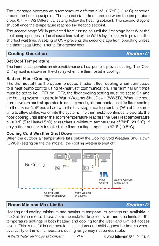
Cooling Operation Section CSet Cool Temperature ----------------------------------------------- -----------------------------------------------
The thermostat operates an air conditioner or a heat pump to provide cooling. The “Cool On” symbol is shown on the display when the thermostat is cooling.
Radiant Floor Cooling ------------------------------------------------ ------------------------------------------------The thermostat has the option to support radiant floor cooling when connected to a heat pump control using tekmarNet® communication. The terminal unit type must be set to be HRF1 or HRF2, the floor cooling setting must be set to On and the heating system must be in Warm Weather Shut Down (WWSD). When the heat pump system control operates in cooling mode, all thermostats set for floor cooling on the tekmarNet® bus all activate the first stage heating contact (W1) at the same time to allow chilled water into the system. The thermostat continues to operate the floor cooling until either the room temperature reaches the Set Heat temperature plus 3°F (Set Heat+1.5°C) or reaches a minimum temperature of 74°F (23.5°C). If only a floor sensor is installed, the floor cooling setpoint is 67°F (19.5°C).
Cooling Cold Weather Shut Down ------------------------------------- -------------------------------------When the outdoor air temperature falls below the Cooling Cold Weather Shut Down
(CWSD) setting on the thermostat, the cooling system is shut off.
The first stage operates on a temperature differential of ±0.7°F (±0.4°C) centered around the heating setpoint. The second stage heat turns on when the temperature drops 0.7°F - W2 Differential setting below the heating setpoint. The second stage is shut off once the temperature reaches the heating setpoint.
The second stage W2 is prevented from turning on until the first stage heat W or the heat pump operates for the elapsed time set by the W2 Delay setting. Auto provides the shortest wait time. A setting of OVR prevents the second stage from operating unless the thermostat Mode is set to Emergency heat.
Warm Weather Shut Down
Cooling Cold Weather Shutdown
FloorCooling
Warmer Outdoor Temperature
No Cooling
Room Min and Max Limits Section DHeating and cooling minimum and maximum temperature settings are available in the Set Temp menu. These allow the installer to select start and stop limits for the temperature settings in both heating and cooling for the User and Limited access levels. This is useful in commercial installations and child / guest bedrooms where availability of the full temperature setting range may not be desirable.
© 2013 553_D - 04/1334 of 48A Watts Water Technologies Company
Hydronic Pump and Valve Operation Section FExercising ---------------------------------------------------------- ----------------------------------------------------------When connected to a tekmarNet® system control, the thermostat exercises the heat relay for 10 seconds every 3 days. Exercising helps prevent zone valves or zone pumps from failing due to precipitate buildup. During exercising, the thermostat shows “TEST” on the display.
Flushing ------------------------------------------------------------ ------------------------------------------------------------The flushing feature is for open-loop systems that use a domestic hot water tank as a heat source. Flushing ensures that fresh potable water is circulated through the system once each day. If the thermostat is connected to a tekmarNet® system control with the Flushing feature turned on, the thermostat display will display “FLUSHING” for the duration of the flushing operation.
Hydronic System Supply Pump --------------------------------------- ---------------------------------------When connected to a tekmarNet® system control, the thermostat’s W1 Pump setting affects how the primary pump or mix pump on the system control operates. When connected to the boiler bus, the boiler system or primary pump is operated. When connected to the mix bus, the mix system pump is operated.
If the thermostat operates a motorized or thermal motor zone valve, the W1 Pump setting should be set to On.
If the thermostat operates a thermal motor (wax actuator) zone valve, set the W1 Thermal Motor setting to On. This provides a three minute delay to allow the zone valve to open before the primary or mix pump is turned on.
In special applications with multiple zoning manifolds, the W1 Pump setting can be set to Off. This allows a Zone Group Pump located on the Zone Manager, or Wiring Center to operate the pump for the manifold.
DHW Tank Priority --------------------------------------------------- ---------------------------------------------------When a tekmarNet® system control is heating an indirect Domestic Hot Water (DHW)
tank, the thermostat may shut off the heating zones to allow the DHW tank to recover
quickly. This is determined by the DHW priority of the tekmarNet® system control.
Mode Operation Section EThe thermostat includes a mode key. Available modes are:
Heat - Allows heating
Cool - Allows cooling
Auto - Automatically switches between heating and cooling as necessary. The interlock time is applied when switching from heating to cooling or from cooling to heating.
Emergency - Only available when operating a heat pump. When set to Emergency the heat pump is locked out and the hydronic and backup heat are operated.
•••
•
© 2013 553_D - 04/1335 of 48A Watts Water Technologies Company
Fan Operation Section G
The fan operates together with the air heating or cooling systems. The user can also select to operate the fan manually by pressing the Fan button. This allows the user to choose between Auto and On. “Auto” allows the fan to operate together with heating or cooling but normally the fan is off. “On” forces the fan to operate continuously.
Ventilation Fan ------------------------------------------------------ ------------------------------------------------------
In order to provide ventilation to the building, the fan can also operate for additional time beyond what is required for the heating and cooling systems. Ventilation allows the user to select the fan to operate for a minimum percentage out of each hour. Options are 10 to 90%, in 10% (6 minutes per hour) increments, as well as Auto and On. This is available when the Vent Mode setting in the Setup menu is set to On.
Once Ventilation is set to On, the Fan minimum run time percentage during the and events can be set so that the fan can operate on a schedule and/or together with scenes.
Fan Post Purge ------------------------------------------------------ ------------------------------------------------------
The fan relay includes a post purge feature that operates the fan after the heating or cooling system has shut off. When a duct temperature sensor is installed the length of post purge is based on the air duct temperature and the Heat Purge or Cool Purge temperature settings. When there is no duct temperature sensor installed, the length of post purge is based upon the Heat Purge and Cool Purge time settings.
Relative Humidity Operation Section HRelative Humidity (RH) is controlled by maintaining the Minimum Humidity using humidification and by maintaining Maximum Humidity using dehumidification. The RH is maintained within a 5% differential. The differential is applied above the minimum setpoint, and applied below the maximum setpoint.
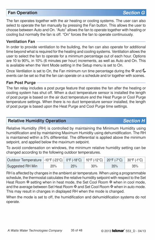
To avoid condensation on windows, the minimum relative humidity setting can be changed according to the following outdoor temperatures.
Outdoor Temperature -10°F (-23°C) 0°F (-18°C) 10°F (-12°C) 20°F (-7°C) 30°F (-1°C)
Suggested RH Min 20% 25% 30% 35% 35%
RH is affected by changes in the ambient air temperature. When using a programmable schedule, the thermostat calculates the relative humidity setpoint with respect to the Set Heat Room setting when in heat mode, the Set Cool Room when in cool mode, and the average between Set Heat Room and Set Cool Room when in auto mode. This may result in changes in displayed RH when the mode is changed.
When the mode is set to off, the humidification and dehumidification systems do not operate.
© 2013 553_D - 04/1336 of 48A Watts Water Technologies Company
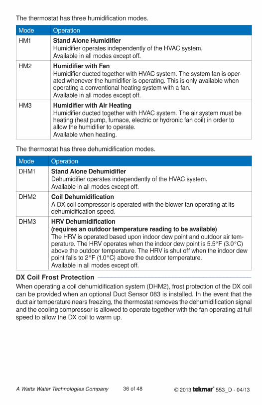
The thermostat has three humidification modes.
Mode Operation
HM1 Stand Alone HumidifierHumidifier operates independently of the HVAC system.Available in all modes except off.
HM2 Humidifier with FanHumidifier ducted together with HVAC system. The system fan is oper-ated whenever the humidifier is operating. This is only available when operating a conventional heating system with a fan.Available in all modes except off.
HM3 Humidifier with Air HeatingHumidifier ducted together with HVAC system. The air system must be heating (heat pump, furnace, electric or hydronic fan coil) in order to allow the humidifier to operate.Available when heating.
The thermostat has three dehumidification modes.
Mode Operation
DHM1 Stand Alone DehumidifierDehumidifier operates independently of the HVAC system.Available in all modes except off.
DHM2 Coil DehumidificationA DX coil compressor is operated with the blower fan operating at its dehumidification speed.
DHM3 HRV Dehumidification(requires an outdoor temperature reading to be available)The HRV is operated based upon indoor dew point and outdoor air tem-perature. The HRV operates when the indoor dew point is 5.5°F (3.0°C) above the outdoor temperature. The HRV is shut off when the indoor dew point falls to 2°F (1.0°C) above the outdoor temperature.Available in all modes except off.
DX Coil Frost Protection --------------------------------------------- ---------------------------------------------
When operating a coil dehumidification system (DHM2), frost protection of the DX coil can be provided when an optional Duct Sensor 083 is installed. In the event that the duct air temperature nears freezing, the thermostat removes the dehumidification signal and the cooling compressor is allowed to operate together with the fan operating at full speed to allow the DX coil to warm up.
© 2013 553_D - 04/1337 of 48A Watts Water Technologies Company
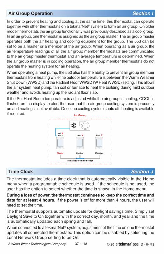
Air Group Operation Section IIn order to prevent heating and cooling at the same time, this thermostat can operate
together with other thermostats on a tekmarNet® system to form an air group. On older
model thermostats the air group functionality was previously described as a cool group.
In an air group, one thermostat is assigned as the air group master. The air group master
operates both the air heating and cooling equipment for the group. The 553 can be
set to be a master or a member of the air group. When operating as a air group, the
air temperature readings of all the air group member thermostats are communicated
to the air group master thermostat and an average temperature is determined. When
the air group master is in cooling operation, the air group member thermostats do not
operate the heating system for air heating.
When operating a heat pump, the 553 also has the ability to prevent air group member
thermostats from heating while the outdoor temperature is between the Warm Weather
Shut Down (WWSD) and the Radiant Floor WWSD (W Heat WWSD) setting. This allows
the air system heat pump, fan coil or furnace to heat the building during mild outdoor
weather and avoids heating up the radiant floor slab.
If the Set Heat Room temperature is adjusted while the air group is cooling, COOL is
flashed on the display to alert the user that the air group cooling system is presently
on and heating is not available. Once the cooling system shuts off, heating is available
if required. Air Group
tekmarNet® Communication
MemberMemberMaster
Time Clock Section JThe thermostat includes a time clock that is automatically visible in the Home menu when a programmable schedule is used. If the schedule is not used, the user has the option to select whether the time is shown in the Home menu.
During a loss of power, the thermostat continues to keep the correct time and date for at least 4 hours. If the power is off for more than 4 hours, the user will need to set the time.
The thermostat supports automatic update for daylight savings time. Simply set Daylight Save to On together with the correct day, month, and year and the time is automatically updated each spring and fall.
When connected to a tekmarNet® system, adjustment of the time on one thermostat updates all connected thermostats. This option can be disabled by selecting the Local Network Group setting to be On.
© 2013 553_D - 04/1338 of 48A Watts Water Technologies Company
Temperature Adjustment Section KPermanent Adjustment - No Schedule -------------------------------- --------------------------------
When no programmable schedule is used, touch the up or down arrows to permanently set the “Set Heat Room” or “Set Cool Room” temperature. This thermostat is capable of controlling both air and floor temperature.
Permanent Adjustment - With Schedule ------------------------------- -------------------------------When a programmable schedule is used, there are two room heating temperatures available, one for the time period and another for the time period. When touching the or arrows to change the temperature, only the temperature for the current time period is changed.
1. To adjust the temperature for both time periods, press and hold the Home button for 3 seconds to enter the programming menus.
2. Enter the “SET TEMP” menu to adjust the following settings:
Set Heat Room (air heating or air heating with floor sensor)
Set Heat Room (air heating or air heating with floor sensor)
Set Heat Room AWAY (air heating or air heating with floor sensor)
Floor Min (air heating with floor sensor)
Floor Min (air heating with floor sensor)
Set Cool Room (air cooling)
Set Cool Room (air cooling)
Set Cool Room AWAY (air cooling)
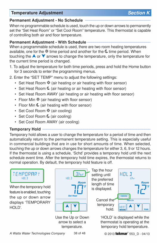
Temporary Hold ----------------------------------------------------- -----------------------------------------------------
Temporary hold allows a user to change the temperature for a period of time and then automatically return to the permanent temperature setting. This is especially useful in commercial buildings that are in use for short amounts of time. When selected, touching the up or down arrows changes the temperature for either 3, 6, 9 or 12 hours. If the thermostat is using a schedule, ‘Schd’ provides a temporary hold until the next schedule event time. After the temporary hold time expires, the thermostat returns to normal operation. By default, the temporary hold feature is off.
•
•
•
•
•
•
•
•
When the temporary hold
feature is enabled, touching
the up or down arrow
displays ‘TEMPORARY
HOLD’.
Use the Up or Down arrow to select a
temperature.
Tap the hour setting until the preferred length of time is displayed.
Cancel the temporary
hold.
‘HOLD’ is displayed while the thermostat is operating at the temporary hold temperature.
© 2013 553_D - 04/1339 of 48A Watts Water Technologies Company
Programmable Schedules Section L
Energy savings can be achieved by lowering the heating temperature and increasing the cooling temperature when the building is unoccupied or during the night.
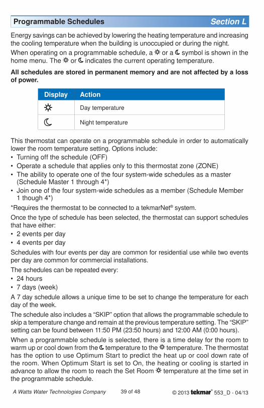
When operating on a programmable schedule, a or a symbol is shown in the home menu. The or indicates the current operating temperature.
All schedules are stored in permanent memory and are not affected by a loss of power.
Display Action
Day temperature
Night temperature
This thermostat can operate on a programmable schedule in order to automatically lower the room temperature setting. Options include:
Turning off the schedule (OFF)
Operate a schedule that applies only to this thermostat zone (ZONE)
The ability to operate one of the four system-wide schedules as a master (Schedule Master 1 through 4*)
Join one of the four system-wide schedules as a member (Schedule Member 1 though 4*)
*Requires the thermostat to be connected to a tekmarNet® system.
Once the type of schedule has been selected, the thermostat can support schedules that have either:
2 events per day
4 events per day
Schedules with four events per day are common for residential use while two events per day are common for commercial installations.
The schedules can be repeated every:
24 hours
7 days (week)
A 7 day schedule allows a unique time to be set to change the temperature for each day of the week.
The schedule also includes a “SKIP” option that allows the programmable schedule to skip a temperature change and remain at the previous temperature setting. The “SKIP” setting can be found between 11:50 PM (23:50 hours) and 12:00 AM (0:00 hours).
When a programmable schedule is selected, there is a time delay for the room to warm up or cool down from the temperature to the temperature. The thermostat has the option to use Optimum Start to predict the heat up or cool down rate of the room. When Optimum Start is set to On, the heating or cooling is started in advance to allow the room to reach the Set Room temperature at the time set in the programmable schedule.
•
•
•
•
•
•
•
•
© 2013 553_D - 04/1340 of 48A Watts Water Technologies Company
Scenes (System Override) Section MScenes provide an easy way to save energy while away on vacation, or override a programmable schedule when plans change.
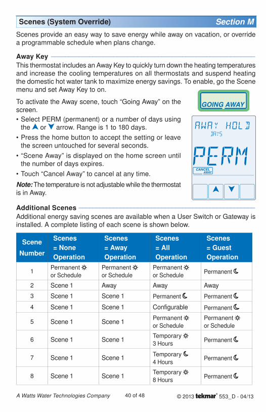
Away Key ----------------------------------------------------------- -----------------------------------------------------------This thermostat includes an Away Key to quickly turn down the heating temperatures and increase the cooling temperatures on all thermostats and suspend heating the domestic hot water tank to maximize energy savings. To enable, go the Scene menu and set Away Key to on.
Additional Scenes --------------------------------------------------- ---------------------------------------------------Additional energy saving scenes are available when a User Switch or Gateway is installed. A complete listing of each scene is shown below.
Scene
Number
Scenes = NoneOperation
Scenes= AwayOperation
Scenes = AllOperation
Scenes= GuestOperation
1Permanent
or Schedule
Permanent
or Schedule
Permanent
or SchedulePermanent
2 Scene 1 Away Away Away
3 Scene 1 Scene 1 Permanent Permanent
4 Scene 1 Scene 1 Configurable Permanent
5 Scene 1 Scene 1Permanent
or Schedule
Permanent
or Schedule
6 Scene 1 Scene 1Temporary
3 HoursPermanent
7 Scene 1 Scene 1Temporary
4 HoursPermanent
8 Scene 1 Scene 1Temporary
8 HoursPermanent
To activate the Away scene, touch “Going Away” on the screen.
Select PERM (permanent) or a number of days using the or arrow. Range is 1 to 180 days.
Press the home button to accept the setting or leave the screen untouched for several seconds.
“Scene Away” is displayed on the home screen until the number of days expires.
Touch “Cancel Away” to cancel at any time.
Note: The temperature is not adjustable while the thermostat is in Away.
•
•
•
•
© 2013 553_D - 04/1341 of 48A Watts Water Technologies Company
Recommendation on How to Use Scenes ----------------------------- ----------------------------- Choosing how to use scenes depends on the needs and lifestyle of the customer using
the building.
Multi-Tenant ApartmentsScenes should be disabled (None) in multi-tenant buildings where each occupant has
differing heating requirements.
Residential HomesSome residential customers may not require scenes, in which case, scenes can be disabled (None). Home owners that wish to save on energy costs should consider using the Away scene to save energy while away from the property (example: vacation or holidays).
The use of the Guest scene is useful in residential applications where there are a number of spare bedrooms that are occupied on an infrequent basis. Each spare bedroom would be setup to operate on the Guest scene. The remaining thermostats can be setup to operate on the None, Away or All scene configuration. Normally, the spare bedrooms would operate at the moon temperature settings. When guests arrive, scene 5 can be activated through the use a User Switch or Gateway. The spare bedroom then operates at the temperature settings or operates on a programmable schedule if a schedule has been setup. When guests depart, the scene can be changed back to scene 1 and
the spare bedrooms resume operation at the temperature settings.
Commercial BuildingsCommercial buildings are typically in use on a predictable schedule and normally the building can operate in scene 1. In order to accommodate staff working overtime or cleaning staff, a 3 or 8 hour temporary override is available when installed in conjunction with a User Switch or Gateway. In these cases, the thermostats should be setup to use the All scene configuration. At the touch of a button, the whole building changes from operating on a programmable schedule (typically at the temperature setting when not occupied) to operating at the temperature settings for 3 hours (scene 6) or 8 hours (scene 8). After the timer counts down and expires, the scene changes back to the previous scene.
Secondary Temperature Display Section NThis thermostat can display the outdoor, floor, relative humidity, or the room heating and cooling temperature settings in the smaller number area at the top right of the screen. To toggle the item currently displayed, touch the secondary temperature. Display of the floor or outdoor temperature requires a connection to an outdoor or floor temperature sensor, or the thermostat is connected to a tekmarNet® system that includes an outdoor sensor. The reading of the outdoor sensor connected directly to the thermostat takes precedence over any outdoor sensor reading available on the tekmarNet® system.
or or or
© 2013 553_D - 04/1342 of 48A Watts Water Technologies Company
tekmarNet® Address Section PWhen connected to a tekmarNet® system, each thermostat will be automatically given an address. The address is useful as a troubleshooting tool to locate thermostats with errors and also allows room naming on a Gateway.
The address consists of the bus water temperature followed by the thermostat device number. Available buses are b (boiler), 1, 2 and 3. Device numbers range from 01 to 24. If the thermostat is used without a tekmarNet® system control, the bus number is not shown.
When using the thermostat together with a Gateway, it is important that each address be changed to be manually set. This allows each thermostat to be named on the Gateway.
If two thermostats are manually set to the same address, an error message will appear. The error remains until one of the addresses is manually changed to a vacant address or to Auto.
It is highly recommended to keep a documented list of thermostat addresses. This is extremely helpful when troubleshooting errors. The tekmarNet® system control will display the addresses of thermostats that have errors. By referring to the address documentation, it simplifies the process to locate and correct error messages.
Access Levels Section OThe thermostat Toolbox menu supports four access levels: Installer (INST), User (USER), Limited (LTD), and Secure (SEC). The access level can be adjusted when the thermostat is unlocked. There are two locations to lock the thermostat:
1. Locally on the thermostat using the Lock switch located in the wiring area.
2. Globally on the tekmarNet® system control using the Lock switch or Access level (if installed)
Both the local and global lock settings must be set to unlock before the thermostat access level is adjustable.
The selection of the access level is dependent on the use of the building and the type of occupants.
Installer - Suitable for HVAC installers only. Times out to User access level after 24 hours.
User - Suitable for most residential homeowners.
Limited - Suitable for rental properties or commercial buildings where some level of temperature adjustment is required.
Secure - Suitable for schools, churches, and other public buildings where temperature adjustment is not desired.
Cleaning the Thermostat Section QEntering the Screen Clean menu allows 30 seconds to clean the thermostat and display with a moist cloth. Do not use solvents to clean the thermostat.
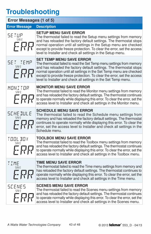
© 2013 553_D - 04/1343 of 48A Watts Water Technologies Company
Error Message Description
SETUP MENU SAVE ERRORThe thermostat failed to read the Setup menu settings from memory and has reloaded the factory default settings. The thermostat stops normal operation until all settings in the Setup menu are checked except to provide freeze protection. To clear the error, set the access level to Installer and check all settings in the Setup menu.
SET TEMP MENU SAVE ERRORThe thermostat failed to read the Set Temp menu settings from memory and has reloaded the factory default settings. The thermostat stops normal operation until all settings in the Set Temp menu are checked except to provide freeze protection. To clear the error, set the access level to Installer and check all settings in the Set Temp menu.
MONITOR MENU SAVE ERRORThe thermostat failed to read the Monitor menu settings from memory and has reloaded the factory default settings. The thermostat continues to operate normally while displaying this error. To clear the error, set the access level to Installer and check all settings in the Monitor menu.
SCHEDULE MENU SAVE ERRORThe thermostat failed to read the Schedule menu settings from memory and has reloaded the factory default settings. The thermostat continues to operate normally while displaying this error. To clear the error, set the access level to Installer and check all settings in the Schedule menu.
TOOLBOX MENU SAVE ERRORThe thermostat failed to read the Toolbox menu settings from memory and has reloaded the factory default settings. The thermostat continues to operate normally while displaying this error. To clear the error, set the access level to Installer and check all settings in the Toolbox menu.
TIME MENU SAVE ERRORThe thermostat failed to read the Time menu settings from memory and has reloaded the factory default settings. The thermostat continues to operate normally while displaying this error. To clear the error, set the access level to Installer and check all settings in the Time menu.
SCENES MENU SAVE ERRORThe thermostat failed to read the Scenes menu settings from memory and has reloaded the factory default settings. The thermostat continues to operate normally while displaying this error. To clear the error, set the access level to Installer and check all settings in the Scenes menu.
TroubleshootingError Messages (1 of 5)
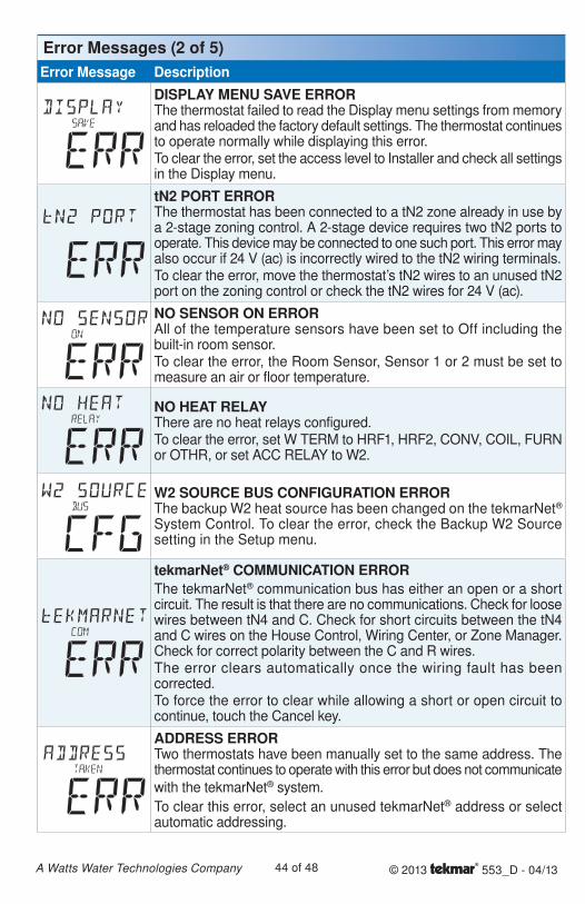
© 2013 553_D - 04/1344 of 48A Watts Water Technologies Company
Error Message DescriptionDISPLAY MENU SAVE ERRORThe thermostat failed to read the Display menu settings from memory and has reloaded the factory default settings. The thermostat continues to operate normally while displaying this error.To clear the error, set the access level to Installer and check all settings in the Display menu.
tN2 PORT ERRORThe thermostat has been connected to a tN2 zone already in use by a 2-stage zoning control. A 2-stage device requires two tN2 ports to operate. This device may be connected to one such port. This error may also occur if 24 V (ac) is incorrectly wired to the tN2 wiring terminals.To clear the error, move the thermostat’s tN2 wires to an unused tN2 port on the zoning control or check the tN2 wires for 24 V (ac).
NO SENSOR ON ERRORAll of the temperature sensors have been set to Off including the built-in room sensor.To clear the error, the Room Sensor, Sensor 1 or 2 must be set to measure an air or floor temperature.
NO HEAT RELAYThere are no heat relays configured.To clear the error, set W TERM to HRF1, HRF2, CONV, COIL, FURN or OTHR, or set ACC RELAY to W2.
W2 SOURCE BUS CONFIGURATION ERRORThe backup W2 heat source has been changed on the tekmarNet® System Control. To clear the error, check the Backup W2 Source setting in the Setup menu.
tekmarNet® COMMUNICATION ERRORThe tekmarNet® communication bus has either an open or a short circuit. The result is that there are no communications. Check for loose wires between tN4 and C. Check for short circuits between the tN4 and C wires on the House Control, Wiring Center, or Zone Manager. Check for correct polarity between the C and R wires.The error clears automatically once the wiring fault has been corrected. To force the error to clear while allowing a short or open circuit to continue, touch the Cancel key.
ADDRESS ERRORTwo thermostats have been manually set to the same address. The thermostat continues to operate with this error but does not communicate
with the tekmarNet® system.
To clear this error, select an unused tekmarNet® address or select automatic addressing.
Error Messages (2 of 5)
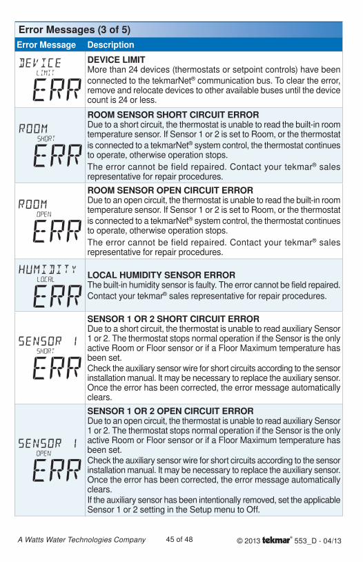
© 2013 553_D - 04/1345 of 48A Watts Water Technologies Company
Error Message Description
DEVICE LIMITMore than 24 devices (thermostats or setpoint controls) have been
connected to the tekmarNet® communication bus. To clear the error, remove and relocate devices to other available buses until the device count is 24 or less.
ROOM SENSOR SHORT CIRCUIT ERRORDue to a short circuit, the thermostat is unable to read the built-in room temperature sensor. If Sensor 1 or 2 is set to Room, or the thermostat
is connected to a tekmarNet® system control, the thermostat continues to operate, otherwise operation stops.
The error cannot be field repaired. Contact your tekmar® sales representative for repair procedures.
ROOM SENSOR OPEN CIRCUIT ERRORDue to an open circuit, the thermostat is unable to read the built-in room temperature sensor. If Sensor 1 or 2 is set to Room, or the thermostat
is connected to a tekmarNet® system control, the thermostat continues to operate, otherwise operation stops.
The error cannot be field repaired. Contact your tekmar® sales representative for repair procedures.
LOCAL HUMIDITY SENSOR ERRORThe built-in humidity sensor is faulty. The error cannot be field repaired.
Contact your tekmar® sales representative for repair procedures.
SENSOR 1 OR 2 SHORT CIRCUIT ERRORDue to a short circuit, the thermostat is unable to read auxiliary Sensor 1 or 2. The thermostat stops normal operation if the Sensor is the only active Room or Floor sensor or if a Floor Maximum temperature has been set.Check the auxiliary sensor wire for short circuits according to the sensor installation manual. It may be necessary to replace the auxiliary sensor. Once the error has been corrected, the error message automatically clears.
SENSOR 1 OR 2 OPEN CIRCUIT ERRORDue to an open circuit, the thermostat is unable to read auxiliary Sensor 1 or 2. The thermostat stops normal operation if the Sensor is the only active Room or Floor sensor or if a Floor Maximum temperature has been set.Check the auxiliary sensor wire for short circuits according to the sensor installation manual. It may be necessary to replace the auxiliary sensor. Once the error has been corrected, the error message automatically clears.If the auxiliary sensor has been intentionally removed, set the applicable Sensor 1 or 2 setting in the Setup menu to Off.
Error Messages (3 of 5)
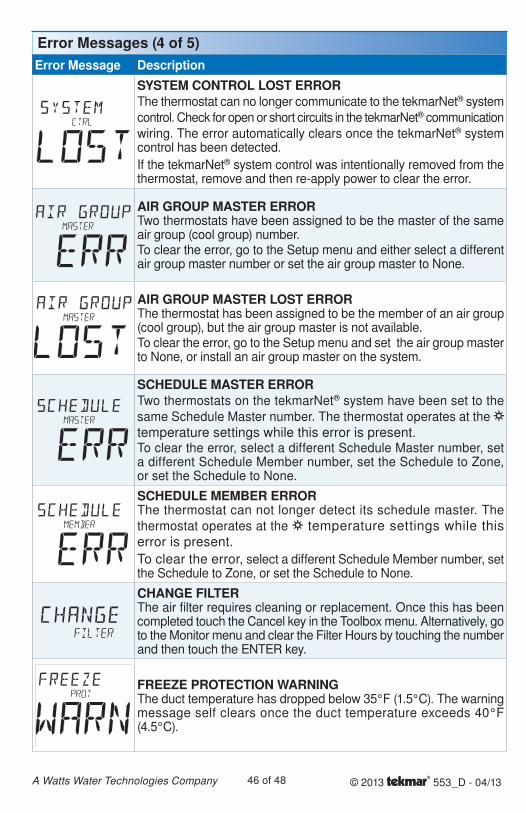
© 2013 553_D - 04/1346 of 48A Watts Water Technologies Company
Error Message DescriptionSYSTEM CONTROL LOST ERRORThe thermostat can no longer communicate to the tekmarNet® system
control. Check for open or short circuits in the tekmarNet® communication
wiring. The error automatically clears once the tekmarNet® system control has been detected.
If the tekmarNet® system control was intentionally removed from the thermostat, remove and then re-apply power to clear the error.
AIR GROUP MASTER ERRORTwo thermostats have been assigned to be the master of the same air group (cool group) number.To clear the error, go to the Setup menu and either select a different air group master number or set the air group master to None.
AIR GROUP MASTER LOST ERRORThe thermostat has been assigned to be the member of an air group (cool group), but the air group master is not available.To clear the error, go to the Setup menu and set the air group master to None, or install an air group master on the system.
SCHEDULE MASTER ERRORTwo thermostats on the tekmarNet® system have been set to the
same Schedule Master number. The thermostat operates at the temperature settings while this error is present.To clear the error, select a different Schedule Master number, set a different Schedule Member number, set the Schedule to Zone, or set the Schedule to None.
SCHEDULE MEMBER ERRORThe thermostat can not longer detect its schedule master. The
thermostat operates at the temperature settings while this error is present.
To clear the error, select a different Schedule Member number, set the Schedule to Zone, or set the Schedule to None.
CHANGE FILTERThe air filter requires cleaning or replacement. Once this has been completed touch the Cancel key in the Toolbox menu. Alternatively, go to the Monitor menu and clear the Filter Hours by touching the number and then touch the ENTER key.
FREEZE PROTECTION WARNINGThe duct temperature has dropped below 35°F (1.5°C). The warning message self clears once the duct temperature exceeds 40°F (4.5°C).
Error Messages (4 of 5)
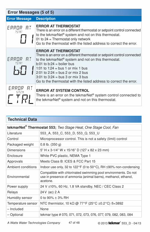
© 2013 553_D - 04/1347 of 48A Watts Water Technologies Company
Error Message Description
ERROR AT THERMOSTATThere is an error on a different thermostat or setpoint control connected
to the tekmarNet® system and not on this thermostat.01 to 24 = Thermostat only networkGo to the thermostat with the listed address to correct the error.
ERROR AT THERMOSTATThere is an error on a different thermostat or setpoint control connected
to the tekmarNet® system and not on this thermostat.b:01 to b:24 = boiler bus1:01 to 1:24 = bus 1 or mix 1 bus2:01 to 2:24 = bus 2 or mix 2 bus3:01 to 3:24 = bus 3 or mix 3 busGo to the thermostat with the listed address to correct the error.
ERROR AT SYSTEM CONTROLThere is an error on the tekmarNet® system control connected to
the tekmarNet® system and not on this thermostat.
Error Messages (5 of 5)
Technical Data
tekmarNet® Thermostat 553; Two Stage Heat, One Stage Cool, Fan
Literature 553_A, 553_C, 553_D, 553_Q, 553_U
Control Microprocessor control. This is not a safety (limit) control
Packaged weight 0.8 lb. (350 g)
Dimensions 5” H x 3-1/4” W x 15/16” D (127 x 82 x 23 mm)
Enclosure White PVC plastic, NEMA Type 1
Approvals Meets Class B: ICES & FCC Part 15
Ambient conditions Indoor use only, 32 to 122°F (0 to 50°C), RH ≤90% non-condensing
EnvironmentalCompatible with chlorinated swimming pool environments. Do not use in presence of ammonia (animal barns), methanol, ethanol, acetone.
Power supply 24 V ±10%, 60 Hz, 1.8 VA standby, NEC / CEC Class 2
Relays 24 V (ac) 2 A
Humidity sensor 0 to 90% ± 3% RH
Temperature sensor NTC thermistor, 10 kΩ @ 77°F (25°C ±0.2°C) ß=3892
– Included None
– Optional tekmar type # 070, 071, 072, 073, 076, 077, 079, 082, 083, 084
All specifications are subjectto change without notice
48 of 48 553_D - 04/13.
Product design, software and literature are Copyright ©2013 by tekmar Control Systems Ltd.,
A Watts Water Technologies Company. Head Offi ce: 5100 Silver Star Road, Vernon, B.C.
Canada V1B 3K4, 250-545-7749, Fax. 250-545-0650 Web Site: www.tekmarControls.com
WARNING: This product contains chemicals known to the State of California to cause cancer and birth defects or other reproductive harm. For more information: www.watts.com/prop65
Limited Warranty The liability of tekmar under this warranty is limited. The Purchaser, by taking receipt of any tekmar product (“Product”), acknowledges the terms of the Limited Warranty in effect at the time of such Product sale and acknowledges that it has read and understands same.
The tekmar Limited Warranty to the Purchaser on the Products sold hereunder is a manufacturer’s pass-through warranty which the Purchaser is authorized to pass through to its customers. Under the Limited Warranty, each tekmar Product is warranted against defects in workmanship and materials if the Product is installed and used in compliance with tekmar’s instructions, ordinary wear and tear excepted. The pass-through warranty period is for a period of twenty-four (24) months from the production date if the Product is not installed during that period, or twelve (12) months from the documented date of installation if installed within twenty-four (24) months from the production date.
The liability of tekmar under the Limited Warranty shall be limited to, at tekmar’s sole discretion: the cost of parts and labor provided by tekmar to repair defects in materials and / or workmanship of the defective product; or to the exchange of the defective product for a warranty replacement product; or to the granting of credit limited to the original cost of the defective product, and such repair, exchange or credit shall be the sole remedy available from tekmar, and, without limiting the foregoing in any way, tekmar is not responsible, in contract, tort or strict product liability, for any other losses, costs, expenses, inconveniences, or damages, whether direct, indirect, special, secondary, incidental or consequential, arising from ownership or use of the product, or from defects in workmanship or materials, including any liability for fundamental breach of contract.
The pass-through Limited Warranty applies only to those defective Products returned to tekmar during the war-ranty period. This Limited Warranty does not cover the cost of the parts or labor to remove or transport the defec-tive Product, or to reinstall the repaired or replacement Product, all such costs and expenses being subject to Purchaser’s agreement and warranty with its customers.
Any representations or warranties about the Products made by Purchaser to its customers which are different from or in excess of the tekmar Limited Warranty are the Purchaser’s sole responsibility and obligation. Purchaser shall indemnify and hold tekmar harmless from and against any and all claims, liabilities and damages of any kind or nature which arise out of or are related to any such representations or warranties by Purchaser to its customers.
The pass-through Limited Warranty does not apply if the returned Product has been damaged by negligence by persons other than tekmar, accident, fire, Act of God, abuse or misuse; or has been damaged by modifications, alterations or attachments made subsequent to purchase which have not been authorized by tekmar; or if the Prod-uct was not installed in compliance with tekmar’s instructions and / or the local codes and ordinances; or if due to defective installation of the Product; or if the Product was not used in compliance with tekmar’s instructions.
THIS WARRANTY IS IN LIEU OF ALL OTHER WARRANTIES, EXPRESS OR IMPLIED, WHICH THE GOVERNING LAW ALLOWS PARTIES TO CONTRACTUALLY EXCLUDE, INCLUDING, WITHOUT LIMITATION, IMPLIED WAR-RANTIES OF MERCHANTABILITY AND FITNESS FOR A PARTICULAR PURPOSE, DURABILITY OR DESCRIP-TION OF THE PRODUCT, ITS NON-INFRINGEMENT OF ANY RELEVANT PATENTS OR TRADEMARKS, AND ITS COMPLIANCE WITH OR NON-VIOLATION OF ANY APPLICABLE ENVIRONMENTAL, HEALTH OR SAFETY LEGISLATION; THE TERM OF ANY OTHER WARRANTY NOT HEREBY CONTRACTUALLY EXCLUDED IS LIM-ITED SUCH THAT IT SHALL NOT EXTEND BEYOND TWENTY-FOUR (24) MONTHS FROM THE PRODUCTION DATE, TO THE EXTENT THAT SUCH LIMITATION IS ALLOWED BY THE GOVERNING LAW.
Product Warranty Return Procedure All Products that are believed to have defects in workmanship or materi-als must be returned, together with a written description of the defect, to the tekmar Representative assigned to the territory in which such Product is located. If tekmar receives an inquiry from someone other than a tekmar Representative, including an inquiry from Purchaser (if not a tekmar Representative) or Purchaser’s customers, regarding a potential warranty claim, tekmar’s sole obligation shall be to provide the address and other contact information regarding the appropriate Representative.
Limited Warranty and Product Return Procedure