Embed Size (px)
Citation preview

ZODIAC CH 601Series Kit Aircraft
THE FOLLOWING IS A DRAFT MANUAL
This manual has been written and published strictly for informational purpose. It hasbeen prepared as a guide to facilitate the assembly of the ZODIAC CH 601 kit aircraft. Itis published to supplement (and not replace) the Zenair drawings and manuals. If adiscrepancy arises between this informational manual and the Drawings, the Drawingsalways take precedence.
All pictures, diagrams, drawings or graphs, are used for general identification only, andare not to be taken to represent technical drawings or replicas of exact parts. You shouldnot consider the educational material in the manual to be the practice of general aviationnor is it intended for this manual to be a complete account of sheet metal aircrafttechnology: It is limited to the scope of the ZODIAC CH 601 aircraft assemblyThis manual is not intended to replace, substitute for or supersede any technicalinformation contained in the ZODIAC CH 601 Drawings and Manuals by Chris Heintz,or other designer’s specifications.
Zenith Aircraft Company (ZAC) nor its authors guarantees the accuracy or completenessof any information published herein and neither ZAC nor its authors shall be responsiblefor any errors, omissions, or damages arising out of use of this information. This guide isprinted with the understanding that ZAC and its authors are supplying information but arenot attempting to render engineering or other professional services. If such services arerequired, the assistance of an appropriate professional should be sought.
Copyright, 1995-2001 Zenith Aircraft Company
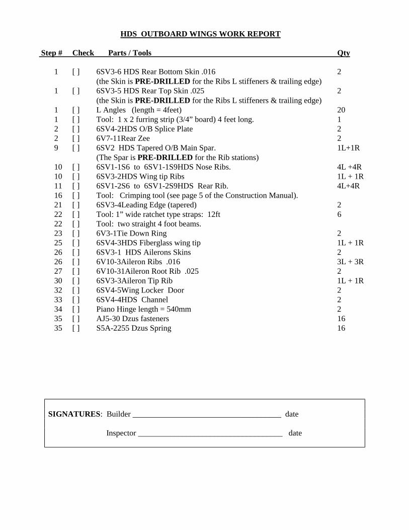
HDS OUTBOARD WINGS WORK REPORT
Step # Check Parts / Tools Qty
1 [ ] 6SV3-6 HDS Rear Bottom Skin .016 2 (the Skin is PRE-DRILLED for the Ribs L stiffeners & trailing edge)
1 [ ] 6SV3-5 HDS Rear Top Skin .025 2(the Skin is PRE-DRILLED for the Ribs L stiffeners & trailing edge)
1 [ ] L Angles (length = 4feet) 201 [ ] Tool: 1 x 2 furring strip (3/4” board) 4 feet long. 12 [ ] 6SV4-2HDS O/B Splice Plate 22 [ ] 6V7-11Rear Zee 29 [ ] 6SV2 HDS Tapered O/B Main Spar. 1L+1R
(The Spar is PRE-DRILLED for the Rib stations)10 [ ] 6SV1-1S6 to 6SV1-1S9HDS Nose Ribs. 4L +4R10 [ ] 6SV3-2HDS Wing tip Ribs 1L + 1R11 [ ] 6SV1-2S6 to 6SV1-2S9HDS Rear Rib. 4L+4R16 [ ] Tool: Crimping tool (see page 5 of the Construction Manual).21 [ ] 6SV3-4Leading Edge (tapered) 222 [ ] Tool: 1” wide ratchet type straps: 12ft 622 [ ] Tool: two straight 4 foot beams.23 [ ] 6V3-1Tie Down Ring 225 [ ] 6SV4-3HDS Fiberglass wing tip 1L + 1R26 [ ] 6SV3-1 HDS Ailerons Skins 226 [ ] 6V10-3Aileron Ribs .016 3L + 3R27 [ ] 6V10-31Aileron Root Rib .025 230 [ ] 6SV3-3Aileron Tip Rib 1L + 1R32 [ ] 6SV4-5Wing Locker Door 233 [ ] 6SV4-4HDS Channel 234 [ ] Piano Hinge length = 540mm 235 [ ] AJ5-30 Dzus fasteners 1635 [ ] S5A-2255 Dzus Spring 16
SIGNATURES: Builder _____________________________________ date
Inspector ____________________________________ date
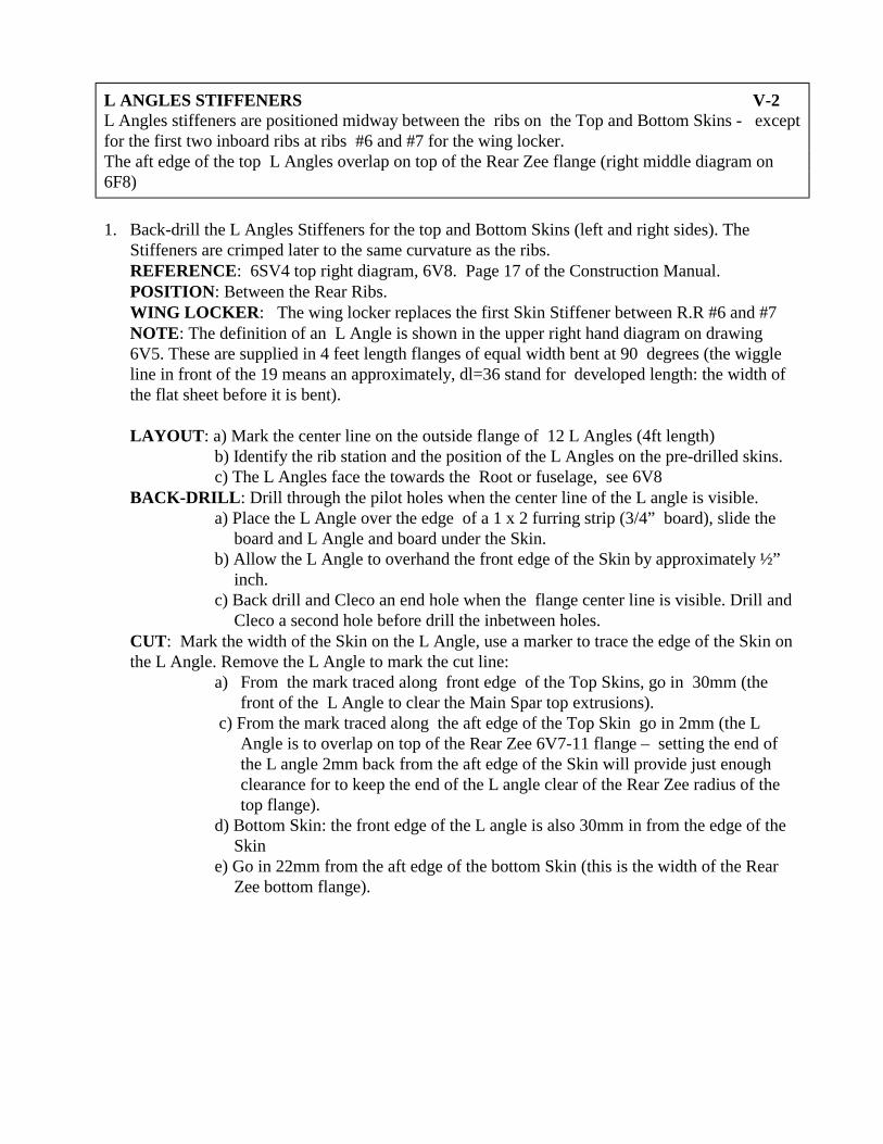
L ANGLES STIFFENERS V-2 L Angles stiffeners are positioned midway between the ribs on the Top and Bottom Skins - exceptfor the first two inboard ribs at ribs #6 and #7 for the wing locker. The aft edge of the top L Angles overlap on top of the Rear Zee flange (right middle diagram on6F8) 1. Back-drill the L Angles Stiffeners for the top and Bottom Skins (left and right sides). The
Stiffeners are crimped later to the same curvature as the ribs. REFERENCE: 6SV4 top right diagram, 6V8. Page 17 of the Construction Manual. POSITION: Between the Rear Ribs. WING LOCKER: The wing locker replaces the first Skin Stiffener between R.R #6 and #7 NOTE: The definition of an L Angle is shown in the upper right hand diagram on drawing6V5. These are supplied in 4 feet length flanges of equal width bent at 90 degrees (the wiggleline in front of the 19 means an approximately, dl=36 stand for developed length: the width ofthe flat sheet before it is bent). LAYOUT: a) Mark the center line on the outside flange of 12 L Angles (4ft length)
b) Identify the rib station and the position of the L Angles on the pre-drilled skins. c) The L Angles face the towards the Root or fuselage, see 6V8
BACK-DRILL: Drill through the pilot holes when the center line of the L angle is visible. a) Place the L Angle over the edge of a 1 x 2 furring strip (3/4” board), slide the
board and L Angle and board under the Skin. b) Allow the L Angle to overhand the front edge of the Skin by approximately ½”
inch. c) Back drill and Cleco an end hole when the flange center line is visible. Drill and
Cleco a second hole before drill the inbetween holes. CUT: Mark the width of the Skin on the L Angle, use a marker to trace the edge of the Skin onthe L Angle. Remove the L Angle to mark the cut line:
a) From the mark traced along front edge of the Top Skins, go in 30mm (thefront of the L Angle to clear the Main Spar top extrusions).
c) From the mark traced along the aft edge of the Top Skin go in 2mm (the LAngle is to overlap on top of the Rear Zee 6V7-11 flange – setting the end ofthe L angle 2mm back from the aft edge of the Skin will provide just enoughclearance for to keep the end of the L angle clear of the Rear Zee radius of thetop flange).
d) Bottom Skin: the front edge of the L angle is also 30mm in from the edge of theSkin
e) Go in 22mm from the aft edge of the bottom Skin (this is the width of the RearZee bottom flange).
© Zenith Aircraft Company: Mexico Memorial Airport, PO Box 650, Mexico, MO 65265 USA (573) 581-9000 FAX: 573-581-0011
Description:
(L) WING SKIN STIFFENERZODIACCH 601
Drawing Rev.
1st Edition: 7-96 V-3V-3
ZODIAC CH 601
WING TOP SKINt=.0252 REQ.
6V8-1
WING BOTTOM SKINt=.0162 REQ.
6V8-2
L
REAR Zee
CRIMP L TO THE SHAPEOF THE RIB
L OVERLAPS UPPERREAR Zee FLANGE
22 mm
30 mm
#9
#8
#7
#6
RIB
30 mm
22 mmA4 A4 A4
A4A4A4
L ANGLES
L ANGLES
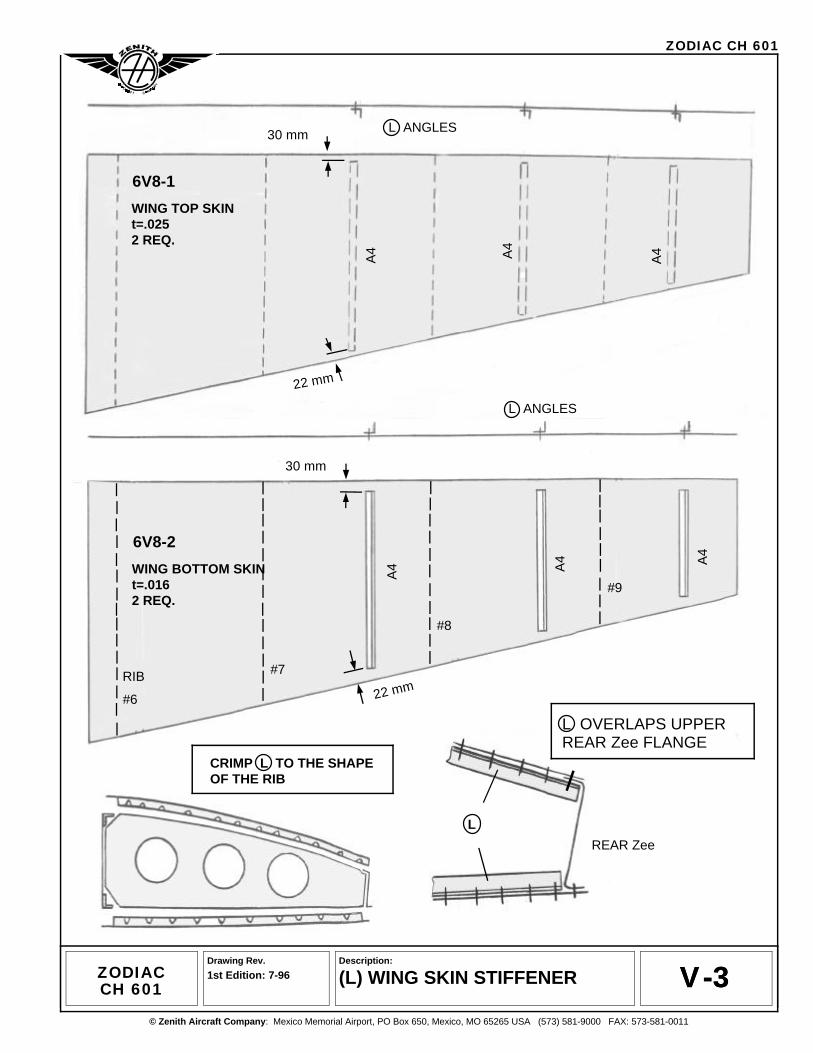
SPLICE PLATE & REAR ZEE LAYOUT V-4 Rib station #6 is layout on the Rear Zee by the positioning the Splice plate: first mark the postionof the Rib at 24mm from the end of the Splice Plate, then position the Splice plate on the Rear Zeeon a 123mm overlap. The remaining Rib are evenly spacing at 571mm from Rib #6. 2. Cleco the Rear O/B Splice Plate 6SV4-2 to the Rear Zee 6V7-11
NOTE : Install the Splice Plate with the 20degrees up and the 33degrees down (reference 6V7– for maximum clearance on the bottom for the Aileron control rod). LAYOUT: a) On the Splice Plate 6SV4-2, mark the position of Rear Rib #6 at 24mm from the
O/B end of the Plate. Rib #6 is designated as “o” on drawing 6SV4 with 5 A5 b) Mark the 4 rivet lines.
NOTE : On the Main Spar, Rib #6 is set at 110mm measured along the top spar extrusion, seebottom right diagram on 6SV1 and top left diagram on 6SV2 PRE-DRILL: With undersize pilot holes #40 CLAMP: The Splice Plate to the Rear Zee, the parts overlap 123mm (2380 - 2257 = 123). CHECK: a) That the bottom of the Splice Plate is positioned at the beginning of the bent
tangent line of the bottom Rear Zee flange. b) The top of the Splice Plate is slightly lower than the top flange of the Rear Zee.b) The end of the Rear Zee is on or just shy of the 15 degree bend tangent line of
the Splice Plate (6SV4-2 is bent 15 degrees towards the front).c) 100mm from the inboard (I/B) end of the Rear Zee to the center line of Rib #6
DRILL & CLECO: a) Back-drill the Rear Zee at Rib #6 with pilot holes #40 b) Back-drill the 4 rivet lines with #20
3. Pre-drill the Rear Zee 6SV4-2 for the Rear Ribs.
LAYOUT: The Ribs are at 90 degrees to the bottom flange of the Rear Zee. The Ribs are evenlyspace 571mm apart starting at Rib #6 CHECK: Hold the Rear Zee along the aft trailing edge of the Skins and check for the Ribalignments with the pre-drilled skins. SUGGESTION: To determine the position of the end holes (top and bottom hole on the RearZee), clamp a Rear Rib to the top flange of Rear Zee to mark the top and bottom end hole forgood edge distances of approximately 10mm. (Referenced from the bottom flange, the threeholes are at: 12, 40 and 70mm). PRE-DRILL: The rib stations with pilot hole #40 in the Rear Zee. The 11 degree flange facesforwards towards the main spar.
4. Cut the O/B end of the Rear Zee 6V7-11 at 45 degrees.
REFERENCE: Rear Zee drawing on the upper left diagram on drawing 6SV4 LAYOUT: The overall length measured along the top flange is 2380mm. CHECK: The distance measured along the top flange from the O/B tip to Rear Rib #9 is567mm.
© Zenith Aircraft Company: Mexico Memorial Airport, PO Box 650, Mexico, MO 65265 USA (573) 581-9000 FAX: 573-581-0011
Description:
POSITION REAR ZEEZODIACCH 601
Drawing Rev.
1st Edition: 7-96 V-5V-5
ZODIAC CH 601
6SV4-2
SPICE PLATEt=0631 REQ.
24
25 428
25
6V7-11
REAR ZEEt=0252 REQ.l=2428
BEN
D
571571 571
#8 #9RIB #716 A5
PILOTHOLE
SPICE PLATE OVERLAPSTHE REAR ZEE 123mm
RIGHT WING
CUT TIP AT45 deg.
PILOT HOLES
33 deg.
20 deg.
UP
10
20
20
20
10
2380
PILOT HOLESRIB STATION #6
15 mm RADIUS TOPILOT HOLE
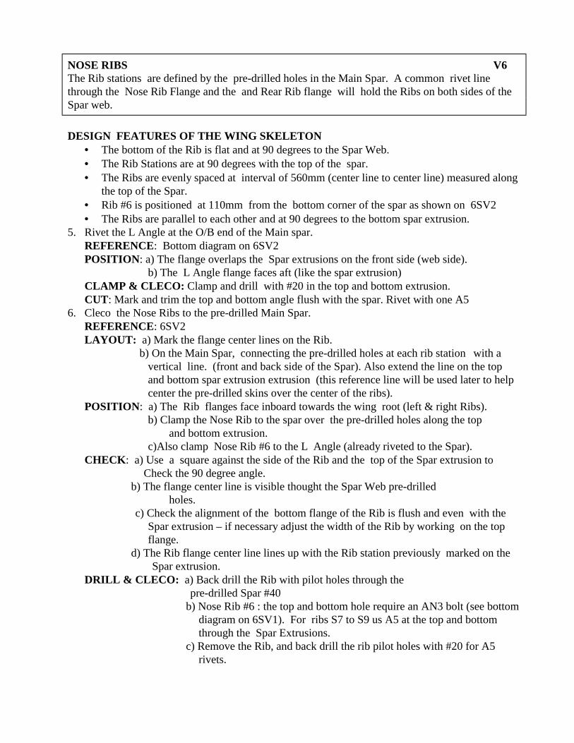
NOSE RIBS V6 The Rib stations are defined by the pre-drilled holes in the Main Spar. A common rivet linethrough the Nose Rib Flange and the and Rear Rib flange will hold the Ribs on both sides of theSpar web. DESIGN FEATURES OF THE WING SKELETON
• The bottom of the Rib is flat and at 90 degrees to the Spar Web.• The Rib Stations are at 90 degrees with the top of the spar.• The Ribs are evenly spaced at interval of 560mm (center line to center line) measured along
the top of the Spar.• Rib #6 is positioned at 110mm from the bottom corner of the spar as shown on 6SV2• The Ribs are parallel to each other and at 90 degrees to the bottom spar extrusion.
5. Rivet the L Angle at the O/B end of the Main spar. REFERENCE: Bottom diagram on 6SV2 POSITION: a) The flange overlaps the Spar extrusions on the front side (web side).
b) The L Angle flange faces aft (like the spar extrusion) CLAMP & CLECO: Clamp and drill with #20 in the top and bottom extrusion. CUT: Mark and trim the top and bottom angle flush with the spar. Rivet with one A5
6. Cleco the Nose Ribs to the pre-drilled Main Spar.REFERENCE: 6SV2 LAYOUT: a) Mark the flange center lines on the Rib.
b) On the Main Spar, connecting the pre-drilled holes at each rib station with avertical line. (front and back side of the Spar). Also extend the line on the topand bottom spar extrusion extrusion (this reference line will be used later to helpcenter the pre-drilled skins over the center of the ribs).
POSITION: a) The Rib flanges face inboard towards the wing root (left & right Ribs). b) Clamp the Nose Rib to the spar over the pre-drilled holes along the top
and bottom extrusion. c)Also clamp Nose Rib #6 to the L Angle (already riveted to the Spar).
CHECK: a) Use a square against the side of the Rib and the top of the Spar extrusion to Check the 90 degree angle.
b) The flange center line is visible thought the Spar Web pre-drilled holes.
c) Check the alignment of the bottom flange of the Rib is flush and even with theSpar extrusion – if necessary adjust the width of the Rib by working on the topflange.
d) The Rib flange center line lines up with the Rib station previously marked on theSpar extrusion.
DRILL & CLECO: a) Back drill the Rib with pilot holes through the pre-drilled Spar #40
b) Nose Rib #6 : the top and bottom hole require an AN3 bolt (see bottomdiagram on 6SV1). For ribs S7 to S9 us A5 at the top and bottomthrough the Spar Extrusions.
c) Remove the Rib, and back drill the rib pilot holes with #20 for A5rivets.
© Zenith Aircraft Company: Mexico Memorial Airport, PO Box 650, Mexico, MO 65265 USA (573) 581-9000 FAX: 573-581-0011
Description:
NOSE RIBS, SPAR TIP LZODIACCH 601
Drawing Rev.
1st Edition: 7-96 V-7V-7
ZODIAC CH 601
NOSE RIBS
PILOTHOLE
571571
571
560560560
A5 RIVET
L
45 deg
REAR VIEW
AN3 BOLT(TOP AND BOTTOMTHROUGH RIB ANDSPAR)
4R+4Lt=025
6SV1-1S9
1S8
1S7
1S6
RIGHT WING SKELETON TOP VIEW
RIB #6
7A5L AND RIB
A5
A5
A5
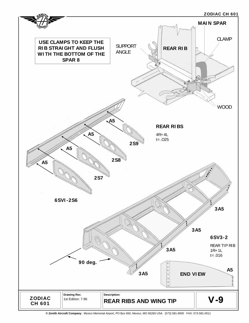
REAR RIBS & REAR TIP RIB V-8 Clamp a support angle along the front side of the Rib to help center the Ribs (up and down) on theSpar; unsupported, the day-light corners on the Rear Ribs (the cutout to clear the top and bottomSpar extrusion) make it difficult to judge when the rib is centered. 7. Cleco the Rear Ribs to the Main Spar one at a time with none of the Nose Ribs in place.
REFERENCE: 6SV2 NOTE: The Bottom flange of the Ribs makes a straight line with the bottom of the Spar. Ifnecessary adjust the top flange of the Rib to make it fit the width of the Spar. LAYOUT: Separate the left and right ribs. Mark the Rib flange center line on all flanges. POSITION: Since the Rear Bibs have a “day-light” corners to clear the spar extrusions, asupport fixture (such as a 2 x 2 board or a length of extrusion) is clamped to the side of the ribwhile it is drilled to the Spar.
a) With the Spar flat on the table hold a rib against the spar web to position thesupport fixture across the Spar Extrusions (6SV2-2 and 6SV2-3). In this positionclamp the support to the Rib.
c) The support fixture is now clamp to the Spar. Carefully center the rib flange overthe pre-drilled pilot holes flush with the top and bottom extrusions.
CHECK: That the “day-light corner” flange clears the Spar Extrusion at the top and bottom. The bottom of the Rib is flush with the Spar, if the Rib is too wide adjust the top flange. DRILL & CLECO: With #20
8. Rivet the skeleton together. Tighten the AN3-6A bolts through the Spar Cap at Rib #6, refer tothe toque table on page 7 of the Manual.
9. Cleco the Rear Zee to the Ribs. REFERENCE: 6SV2 NOTE: The Rear Zee (top flange) overlaps on top of the Rib (see right middle
diagram on 6V8). CLAMP: Clamp the top flanges together, and the Rib rear flange to the Zee web. CHECK: a) Use an adjustable square against the side of the rib and the bottom of the Rear Zee
to check the 90 degree angle. b) The flange centerline is visible through the pre-drill holes. c) The bottom of the rib is flush with the bottom flange of the Rear Zee. d) The rear Rib flange makes full contact with the Rear Zee web. Hand band the
flange to match the correct angle to eliminate any separation or gap along the edgeof the flange and the spar web.
DRILL & CLECO: #30 RIVET: a) The Splice Plate 6SV4-2 to the Rear Zee
b) The Rear Ribs to the Rear Zee.10. Cleco the Rear Tip Rib 6SV3-2 at the end of the Spar.
CLAMP: Clamp the Rear Tip Rib to the L Angle on the Main Spar and the rear flange of theRear Tip Rib to the Rear Zee.DRILL & CLECO: Reference drawing 6SV4; 7A4 in the L Angle and 3 A4 in the Rear Zee.Wait to rivet, it may be necessary to remove the Rib to install the Fiberglass Tip 6SV4-3
© Zenith Aircraft Company: Mexico Memorial Airport, PO Box 650, Mexico, MO 65265 USA (573) 581-9000 FAX: 573-581-0011
Description:
REAR RIBS AND WING TIPZODIACCH 601
Drawing Rev.
1st Edition: 7-96 V-9V-9
USE CLAMPS TO KEEP THERIB STRAIGHT AND FLUSHWITH THE BOTTOM OF THE
SPAR 8
A5END VIEW
2S7
2S8
2S9
REAR RIBS
4R+4Lt=.O25
3A5
3A5
3A5
3A5
6SVI-2S6
90 deg.
A5
A5
A5
A5
6SV3-2
REAR TIP RIB1R+1Lt=.016
SUPPORTANGLE
ZODIAC CH 601
MAIN SPAR
CLAMP
REAR RIB
WOOD
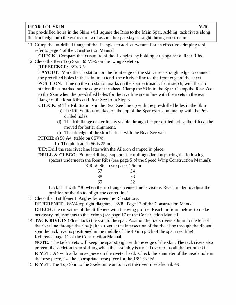
REAR TOP SKIN V-10 The pre-drilled holes in the Skins will square the Ribs to the Main Spar. Adding tack rivets alongthe front edge into the extrusion will assure the spar stays straight during construction.11. Crimp the un-drilled flange of the L angles to add curvature. For an effective crimping tool,
refer to page 4 of the Construction Manual CHECK : Compare the curvature of the L angles by holding it up against a Rear Ribs.
12. Cleco the Rear Top Skin 6SV3-5 on the wing skeleton. REFERENCE: 6SV3-5 LAYOUT: Mark the rib station on the front edge of the skin: use a straight edge to connectthe predrilled holes in the skin to extend the rib rivet line to the front edge of the sheet. POSITION: Line up the rib station marks on the spar extrusion, from step 6, with the ribstation lines marked on the edge of the sheet. Clamp the Skin to the Spar. Clamp the Rear Zeeto the Skin when the pre-drilled holes for the rive line are in line with the rivets in the rearflange of the Rear Ribs and Rear Zee from Step 3 CHECK: a) The Rib Stations in the Rear Zee line up with the pre-drilled holes in the Skin
b) The Rib Stations marked on the top of the Spar extrusion line up with the Pre-drilled holes.
d) The Rib flange center line is visible through the pre-drilled holes, the Rib can bemoved for better alignment.
e) The aft edge of the skin is flush with the Rear Zee web. PITCH: a) 50 A4 (table on 6SV4).
b) The pitch at rib #6 is 25mm. TIP: Drill the rear rivet line later with the Aileron clamped in place. DRILL & CLECO: Before drilling, support the trailing edge by placing the following
spacers underneath the Rear Ribs (see page 5 of the Speed Wing Construction Manual): R.R. # S6 use spacer 25mm
S7 24 S8 23 S9 22
Back drill with #30 when the rib flange center line is visible. Reach under to adjust theposition of the rib to align the center line!
13. Cleco the 3 stiffener L Angles between the Rib stations. REFERENCE: 6SV4 top right diagram, 6V8. Page 17 of the Construction Manual.
CHECK: the curvature of the Stiffeners with the wing profile. Reach in from below to makenecessary adjustments to the crimp (see page 17 of the Construction Manual).
14. TACK RIVETS (Flush tack) the skin to the spar. Position the track rivets 20mm to the left ofthe rivet line through the ribs (with a rivet at the intersection of the rivet line through the rib andspar the tack rivet is positioned in the middle of the 40mm pitch of the spar rivet line).Reference page 11 of the Construction Manual.NOTE: The tack rivets will keep the spar straight with the edge of the skin. The tack rivets alsoprevent the skeleton from shifting when the assembly is turned over to install the bottom skin.RIVET: A4 with a flat nose piece on the riveter head. Check the diameter of the inside hole inthe nose piece, use the appropriate nose piece for the 1/8” rivets!
15. RIVET: The Top Skin to the Skeleton, wait to rivet the rivet lines after rib #9
© Zenith Aircraft Company: Mexico Memorial Airport, PO Box 650, Mexico, MO 65265 USA (573) 581-9000 FAX: 573-581-0011
Description:
REAR TOP WING SKINZODIACCH 601
Drawing Rev.
1st Edition: 7-96(9/97) V-11V-11
ZODIAC CH 601
22 mm
6SV3
TOP SKINl=2440t=.O25
A4PITCH 20
A4PITCH 40
A4PITCH 40
TACK RIVETS
NO RIVETZONE AFTER
RIB S9
OPTIONAL LEVEL BEAM(OR USE FLAT WORK BENCH)
23 mm
24 mm
25mmSHIM
10 mm offset to Ribcenterline
POSITION THE FRONTCORNER OF THE TOP
SKIN FLUSH WITHTHE SPAR
POSITION THE AFTEDGE OF THE TOP
SKIN FLUSH WITH THEREAR ZEE
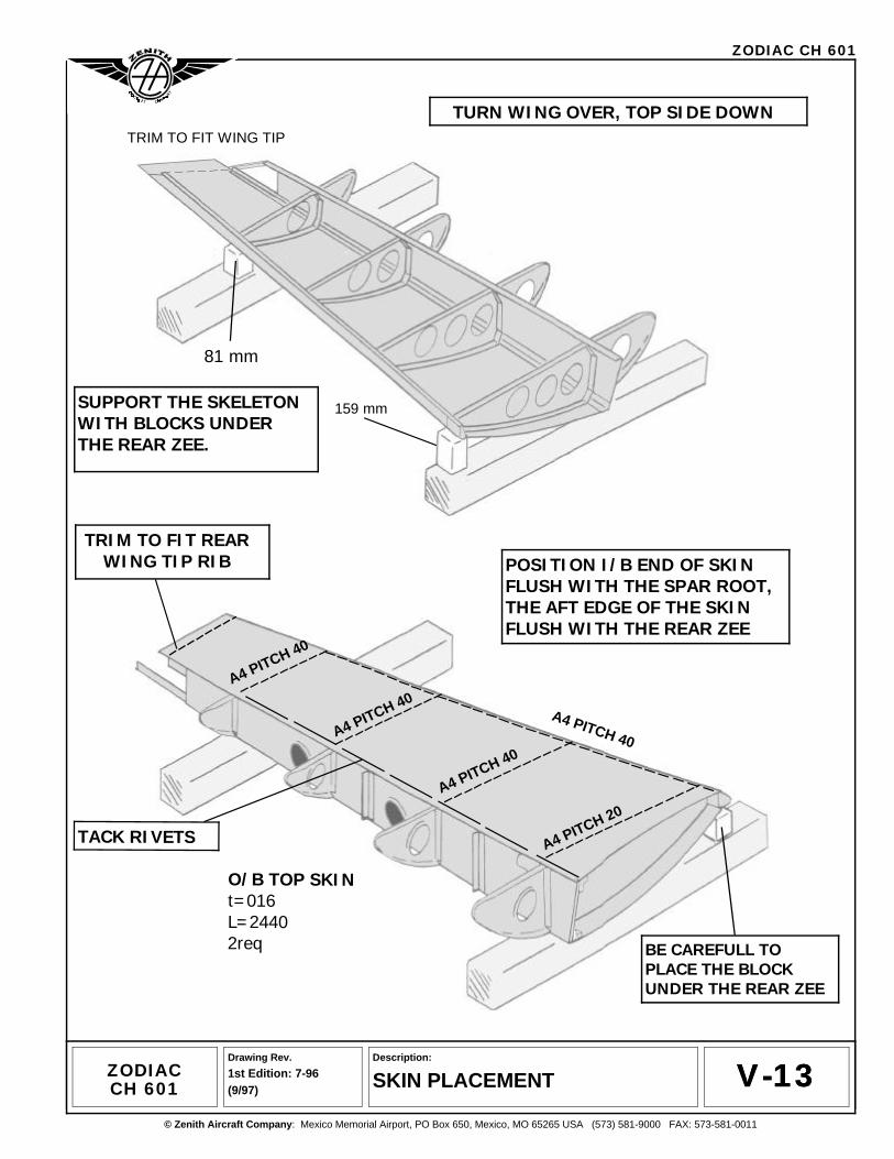
REAR BOTTOM SKIN V-12 Turn the wing over, and support the trailing edge. 16. Crimp the L angles using the bottom curvature of the ribs as a guide.17. Position the Bottom Skin 6SV3-6.
REFERENCE: 6SV3-6, 6SV1-2 SUPPORT: Support the Ribs at the rear using the following block spacers:
S6 159 S7 133 S8 107 S9 81
Subtract upper coordinate U from the last station X from station 0 add 2mm for thethickness of the top skin as shown drawing 6SV1 . Example for S6: 264 –107 + 2 = 159
POSITION: a) The aft edge flush with the Zee. b) The I/B end is flush with the Root of the Main Spar.
LAYOUT: Mark the rib station on the front edge of the skin: use a straight edge to connect thepredrilled holes in the skin to extend the rib rivet line to the front edge of thesheet.
POSITION: Line up the rib station marks on the spar extrusion, from step 6, with the ribstation lines marked on the edge of the sheet. Clamp the skin to the Spar. Clampthe Rear Zee to the Skin when the pre-drilled holes for the rive line are in line withthe rivets in the rear flange of the Rear Ribs and Rear Zee from Step 3
CHECK: a) The pre-drilled holes in the Skin for the aft rivet line for the Rear Zee are in themiddle of the flange.
b) The front edge of the skin is flush with the spar. b) The pre-drilled holes for the rib rivet line are in line with the rib.
PITCH: a) 50 A4 (table on 6SV4). b) The pitch at rib #6 is 25mm.
18. L ANGLES: Crimp and Install the L Angles19. TACK RIVETS the front edge of the skin to the spar.20. CLECO & RIVET: De-burrs.
© Zenith Aircraft Company: Mexico Memorial Airport, PO Box 650, Mexico, MO 65265 USA (573) 581-9000 FAX: 573-581-0011
Description:
SKIN PLACEMENTZODIACCH 601
Drawing Rev.
1st Edition: 7-96(9/97)
V-13V-13
ZODIAC CH 601
SUPPORT THE SKELETONWITH BLOCKS UNDERTHE REAR ZEE.
81 mm
159 mm
POSITION I/B END OF SKINFLUSH WITH THE SPAR ROOT,THE AFT EDGE OF THE SKINFLUSH WITH THE REAR ZEE
TURN WING OVER, TOP SIDE DOWN
TACK RIVETS
A4 PITCH 40
A4 PITCH 20
A4 PITCH 40A4 PITCH 40
A4 PITCH 40
TRIM TO FIT WING TIP
O/B TOP SKINt=016L=24402req BE CAREFULL TO
PLACE THE BLOCKUNDER THE REAR ZEE
TRIM TO FIT REARWING TIP RIB
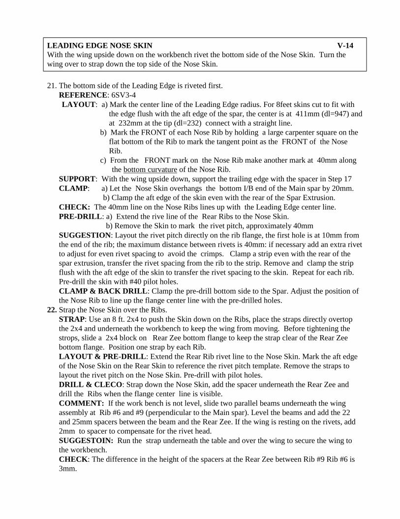
LEADING EDGE NOSE SKIN V-14 With the wing upside down on the workbench rivet the bottom side of the Nose Skin. Turn thewing over to strap down the top side of the Nose Skin. 21. The bottom side of the Leading Edge is riveted first.
REFERENCE: 6SV3-4 LAYOUT: a) Mark the center line of the Leading Edge radius. For 8feet skins cut to fit with
the edge flush with the aft edge of the spar, the center is at 411mm (dl=947) andat 232mm at the tip (dl=232) connect with a straight line.
b) Mark the FRONT of each Nose Rib by holding a large carpenter square on theflat bottom of the Rib to mark the tangent point as the FRONT of the NoseRib.
c) From the FRONT mark on the Nose Rib make another mark at 40mm alongthe bottom curvature of the Nose Rib.
SUPPORT: With the wing upside down, support the trailing edge with the spacer in Step 17 CLAMP: a) Let the Nose Skin overhangs the bottom I/B end of the Main spar by 20mm.
b) Clamp the aft edge of the skin even with the rear of the Spar Extrusion. CHECK: The 40mm line on the Nose Ribs lines up with the Leading Edge center line. PRE-DRILL: a) Extend the rive line of the Rear Ribs to the Nose Skin.
b) Remove the Skin to mark the rivet pitch, approximately 40mm SUGGESTION: Layout the rivet pitch directly on the rib flange, the first hole is at 10mm fromthe end of the rib; the maximum distance between rivets is 40mm: if necessary add an extra rivetto adjust for even rivet spacing to avoid the crimps. Clamp a strip even with the rear of thespar extrusion, transfer the rivet spacing from the rib to the strip. Remove and clamp the stripflush with the aft edge of the skin to transfer the rivet spacing to the skin. Repeat for each rib.Pre-drill the skin with #40 pilot holes. CLAMP & BACK DRILL: Clamp the pre-drill bottom side to the Spar. Adjust the position ofthe Nose Rib to line up the flange center line with the pre-drilled holes.
22. Strap the Nose Skin over the Ribs. STRAP: Use an 8 ft. 2x4 to push the Skin down on the Ribs, place the straps directly overtopthe 2x4 and underneath the workbench to keep the wing from moving. Before tightening thestrops, slide a 2x4 block on Rear Zee bottom flange to keep the strap clear of the Rear Zeebottom flange. Position one strap by each Rib. LAYOUT & PRE-DRILL: Extend the Rear Rib rivet line to the Nose Skin. Mark the aft edgeof the Nose Skin on the Rear Skin to reference the rivet pitch template. Remove the straps tolayout the rivet pitch on the Nose Skin. Pre-drill with pilot holes. DRILL & CLECO: Strap down the Nose Skin, add the spacer underneath the Rear Zee anddrill the Ribs when the flange center line is visible.COMMENT: If the work bench is not level, slide two parallel beams underneath the wingassembly at Rib #6 and #9 (perpendicular to the Main spar). Level the beams and add the 22and 25mm spacers between the beam and the Rear Zee. If the wing is resting on the rivets, add2mm to spacer to compensate for the rivet head.SUGGESTOIN: Run the strap underneath the table and over the wing to secure the wing tothe workbench. CHECK: The difference in the height of the spacers at the Rear Zee between Rib #9 Rib #6 is3mm.
© Zenith Aircraft Company: Mexico Memorial Airport, PO Box 650, Mexico, MO 65265 USA (573) 581-9000 FAX: 573-581-0011
Description:
WING NOSE SKINZODIACCH 601
Drawing Rev.
1st Edition: 7-96(9/97)
V-15V-15
ZODIAC CH 601
TRIM THE AFT EDGE OF THE SKINFLUSH WITH THE AFT EDGE OFTHE BOTTOM SPAR EXTRUSION
REMEMBER TO USE SPACERSTO SUPPORT THE WING
SKIN IS FLUSH WITH I/BEND OF SPAR
PRE-DRILL THE NOSE SKIN FORTHE NOSE RIB IN BETWEEN THECRIMPS
A5 PITCH 40
A5 PITCH 40
A4
6SV3-4NOSE SKIN2 REQ.t=.025l=2440 RIVET BOTTOM SIDE
AND TURN WINGOVER
22 mmSPACER
25 mmSPACER
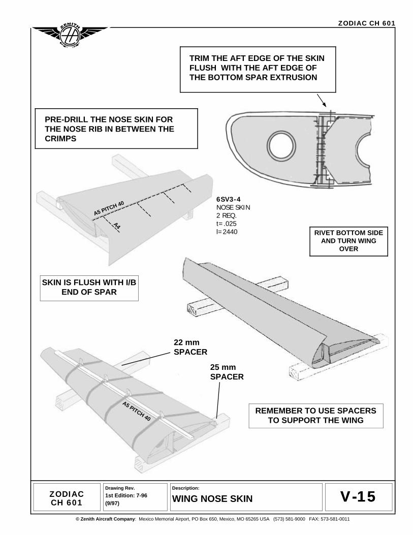
WING TIP V-16Trim the Nose Skin on the same 45 degrees angle as the Rear Tip Rib: tape a marker at the end of ayard stick, lay the yard stick flat on the Tip Rib to trace the Nose Skin. 23. Install the Tie Down Ring 6V3-1 are positioned through the Lower Spar Cap Angle (extrusion)
at 40mm inboard of the most outboard rib as shown on drawing 6V3 section AA (top rightdiagram and bottom right detail).
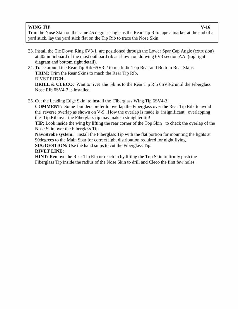
24. Trace around the Rear Tip Rib 6SV3-2 to mark the Top Rear and Bottom Rear Skins.TRIM: Trim the Rear Skins to mach the Rear Tip Rib.RIVET PITCH:DRILL & CLECO: Wait to rivet the Skins to the Rear Tip Rib 6SV3-2 until the FiberglassNose Rib 6SV4-3 is installed.
25. Cut the Leading Edge Skin to install the Fiberglass Wing Tip 6SV4-3COMMENT: Some builders prefer to overlap the Fiberglass over the Rear Tip Rib to avoidthe reverse overlap as shown on V-9 . How the overlap is made is insignificant, overlappingthe Tip Rib over the Fiberglass tip may make a straighter tip!TIP: Look inside the wing by lifting the rear corner of the Top Skin to check the overlap of theNose Skin over the Fiberglass Tip.Nav/Strobe system: Install the Fiberglass Tip with the flat portion for mounting the lights at90degrees to the Main Spar for correct light distribution required for night flying.SUGGESTION: Use the hand snips to cut the Fiberglass Tip.RIVET LINE: HINT: Remove the Rear Tip Rib or reach in by lifting the Top Skin to firmly push theFiberglass Tip inside the radius of the Nose Skin to drill and Cleco the first few holes.
© Zenith Aircraft Company: Mexico Memorial Airport, PO Box 650, Mexico, MO 65265 USA (573) 581-9000 FAX: 573-581-0011
Description:
NOSE RIB INSTALLATIONZODIACCH 601
Drawing Rev.
1st Edition: 7-96(9/97) V-17V-17
ZODIAC CH 601
WING TIP
6SV4-3
NOSE RIBFIBREGLASS2 REQ. (L & R)
TRIM
REAR RIB #9
LIFT REAR TOP SKIN TO REACH INSIDEWITH YOUR ARM, PUSH THE FIBERGLASSPART INSIDE THE NOSE SKIN RADIUS.
A4 PITCH
MARK NOSE SKIN ON A STRAIGHT LINE WITH REAR TIP
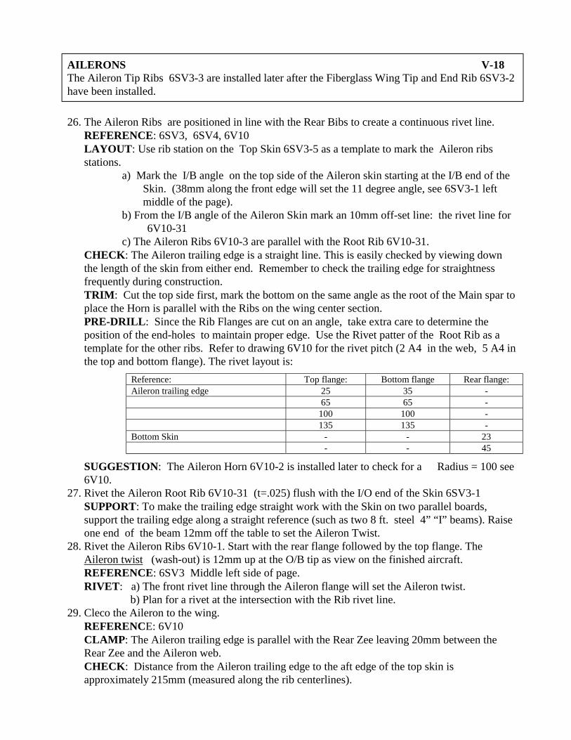
AILERONS V-18 The Aileron Tip Ribs 6SV3-3 are installed later after the Fiberglass Wing Tip and End Rib 6SV3-2have been installed.
26. The Aileron Ribs are positioned in line with the Rear Bibs to create a continuous rivet line. REFERENCE: 6SV3, 6SV4, 6V10 LAYOUT: Use rib station on the Top Skin 6SV3-5 as a template to mark the Aileron ribsstations.
a) Mark the I/B angle on the top side of the Aileron skin starting at the I/B end of theSkin. (38mm along the front edge will set the 11 degree angle, see 6SV3-1 leftmiddle of the page).
b) From the I/B angle of the Aileron Skin mark an 10mm off-set line: the rivet line for6V10-31
c) The Aileron Ribs 6V10-3 are parallel with the Root Rib 6V10-31. CHECK: The Aileron trailing edge is a straight line. This is easily checked by viewing downthe length of the skin from either end. Remember to check the trailing edge for straightnessfrequently during construction. TRIM: Cut the top side first, mark the bottom on the same angle as the root of the Main spar toplace the Horn is parallel with the Ribs on the wing center section. PRE-DRILL: Since the Rib Flanges are cut on an angle, take extra care to determine theposition of the end-holes to maintain proper edge. Use the Rivet patter of the Root Rib as atemplate for the other ribs. Refer to drawing 6V10 for the rivet pitch (2 A4 in the web, 5 A4 inthe top and bottom flange). The rivet layout is:
Reference: Top flange: Bottom flange Rear flange: Aileron trailing edge 25 35 - 65 65 - 100 100 - 135 135 - Bottom Skin - - 23 - - 45
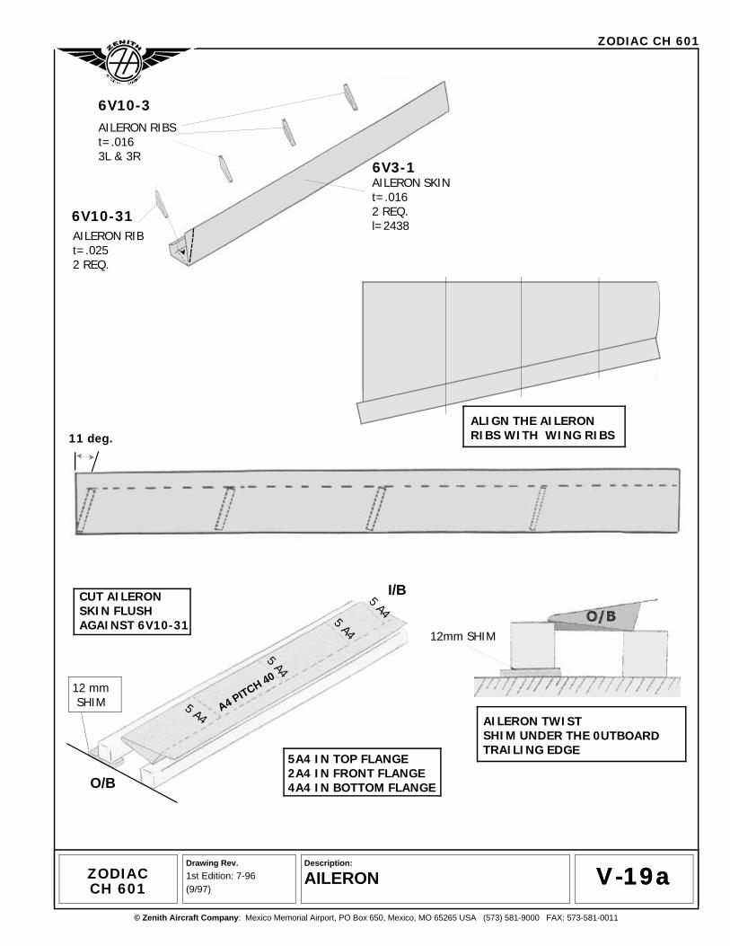
SUGGESTION: The Aileron Horn 6V10-2 is installed later to check for a Radius = 100 see6V10.
27. Rivet the Aileron Root Rib 6V10-31 (t=.025) flush with the I/O end of the Skin 6SV3-1 SUPPORT: To make the trailing edge straight work with the Skin on two parallel boards,support the trailing edge along a straight reference (such as two 8 ft. steel 4” “I” beams). Raiseone end of the beam 12mm off the table to set the Aileron Twist.
28. Rivet the Aileron Ribs 6V10-1. Start with the rear flange followed by the top flange. TheAileron twist (wash-out) is 12mm up at the O/B tip as view on the finished aircraft. REFERENCE: 6SV3 Middle left side of page. RIVET: a) The front rivet line through the Aileron flange will set the Aileron twist.
b) Plan for a rivet at the intersection with the Rib rivet line.29. Cleco the Aileron to the wing.
REFERENCE: 6V10 CLAMP: The Aileron trailing edge is parallel with the Rear Zee leaving 20mm between theRear Zee and the Aileron web. CHECK: Distance from the Aileron trailing edge to the aft edge of the top skin isapproximately 215mm (measured along the rib centerlines).
© Zenith Aircraft Company: Mexico Memorial Airport, PO Box 650, Mexico, MO 65265 USA (573) 581-9000 FAX: 573-581-0011
Description:
AILERONZODIACCH 601
Drawing Rev.
1st Edition: 7-96(9/97)
V-19aV-19a
ZODIAC CH 601
AILERON RIBSt=.0163L & 3R
6V10-3
11 deg.ALIGN THE AILERONRIBS WITH WING RIBS
AILERON SKINt=.0162 REQ.l=2438
6V3-1
AILERON TWISTSHIM UNDER THE 0UTBOARDTRAILING EDGE
AILERON RIBt=.0252 REQ.
6V10-31
I/B
5 A4
A4 PITCH 40
5 A4
5 A4
5 A4
CUT AILERONSKIN FLUSHAGAINST 6V10-31
5A4 IN TOP FLANGE2A4 IN FRONT FLANGE4A4 IN BOTTOM FLANGEO/B
12mm SHIM
12 mmSHIM
© Zenith Aircraft Company: Mexico Memorial Airport, PO Box 650, Mexico, MO 65265 USA (573) 581-9000 FAX: 573-581-0011
Description:
AILERON HORNZODIACCH 601
Drawing Rev.
1st Edition: 7-96(9/97)
V-19bV-19b
ZODIAC CH 601
5/16 in hole
40 100
15
70
98 deg
.
5/16 hole, horn bolted to template10mm raduis to hole center
6V10-2
AILERON HORN2 REQ.
9 RIVETS A5 (EDGE DISTANCE=5mm)
6V10-31
L
POSITIONING
TEMPLATE
PLYWOOD HORNPOSITIONING
TEMPLATE
AILERON TIP V-20 Trim the Aileron tip with the Skin Clecoed to the wing. The Aileron Tip Rib is installed at thesame angle as the Rear Wing Tip Rib 6SV3-2
30. Aileron Tip Ribs 6SV3-3REFERENCE: V-21, 6SV3
31. Aileron Horn 6V10-2REVERENCE: V-19, 6V10, 6V14TEMPLATE: Cut a plywood template (use thin plywood) to fit against and bottom of thefront of the Aileron Skin. Drill a small pilot hole in the template for the horn bolt. Scribe a10mm circle around the pilot hole.POSITION: The Horn is positioned on the Aileron Rib 6V10-31 with reference to the horn boltfor the Rod end. Position the template on the aileron skin flush with the root rib, slide theHorn to fit: flush with the top skin and to completely cover the 10mm scribe circle on thetemplate. Back drill the pilot hole in the template into the Horn.HORN BOLT: 5/16” hole,RADIUS: Radius the end of the Horn around the Horn bolt (minimum radius of 10mm)RIVET: Bolt the Horn to the template, Drill for 9 A5.
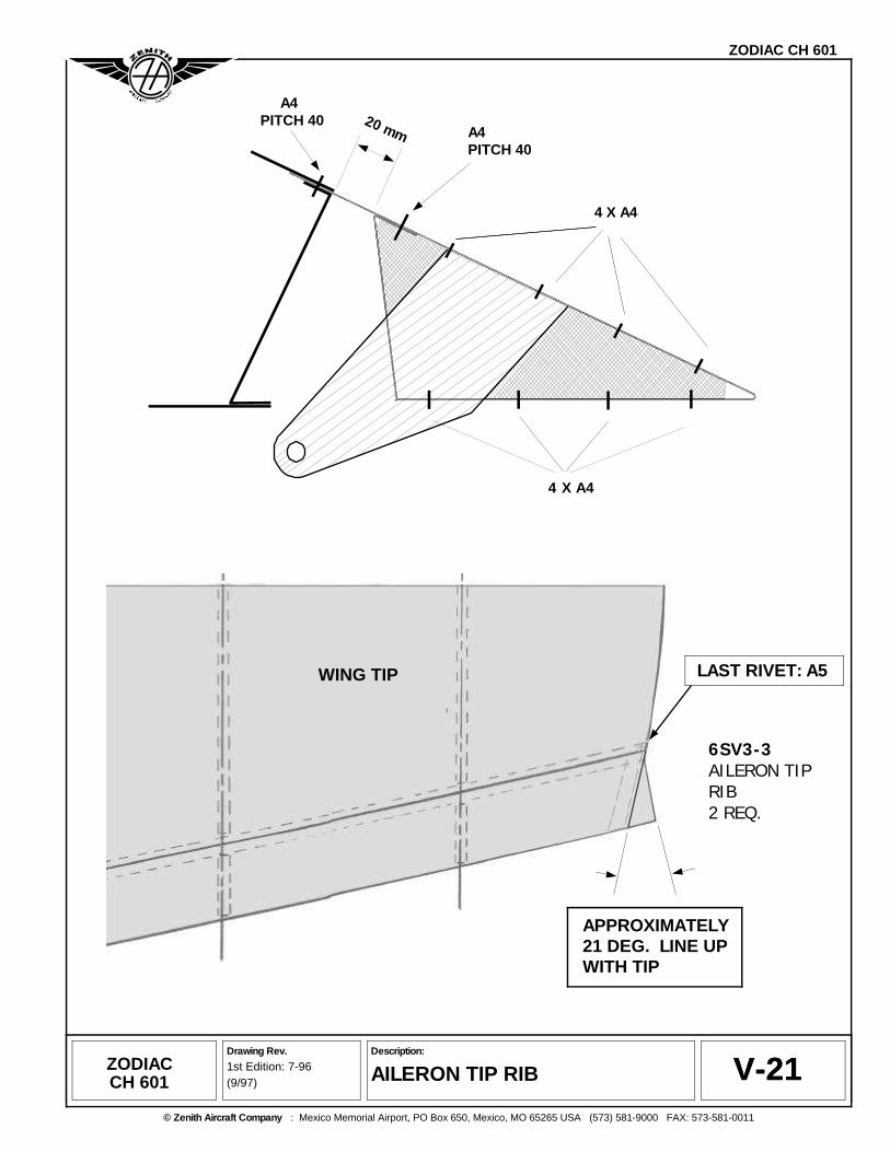
© Zenith Aircraft Company : Mexico Memorial Airport, PO Box 650, Mexico, MO 65265 USA (573) 581-9000 FAX: 573-581-0011
Description:
AILERON TIP RIBZODIACCH 601
Drawing Rev.
1st Edition: 7-96(9/97)
V-21V-21
ZODIAC CH 601
6SV3-3AILERON TIPRIB2 REQ.
WING TIP
A4PITCH 40
APPROXIMATELY21 DEG. LINE UPWITH TIP
LAST RIVET: A5
A4PITCH 40
4 X A4
4 X A4
20 mm
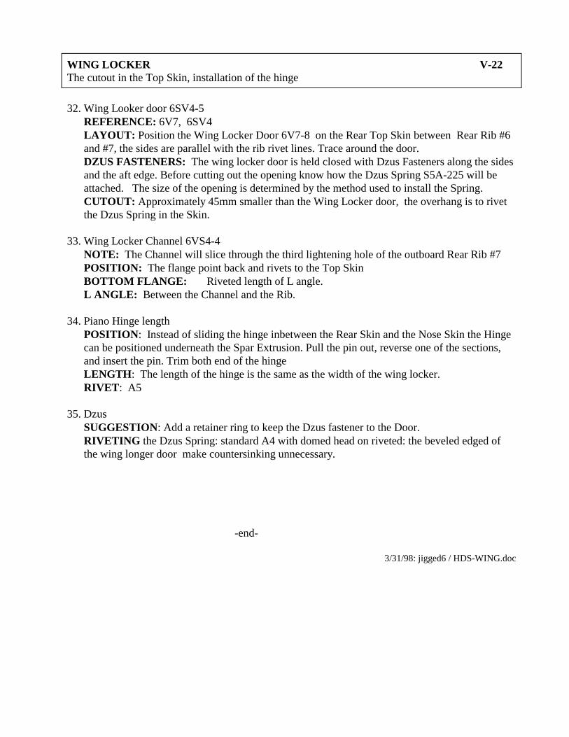
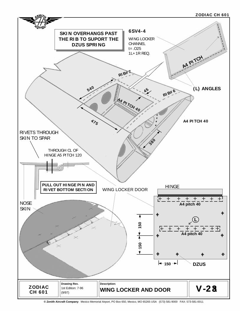
WING LOCKER V-22 The cutout in the Top Skin, installation of the hinge
32. Wing Looker door 6SV4-5REFERENCE: 6V7, 6SV4LAYOUT: Position the Wing Locker Door 6V7-8 on the Rear Top Skin between Rear Rib #6and #7, the sides are parallel with the rib rivet lines. Trace around the door.DZUS FASTENERS: The wing locker door is held closed with Dzus Fasteners along the sidesand the aft edge. Before cutting out the opening know how the Dzus Spring S5A-225 will beattached. The size of the opening is determined by the method used to install the Spring.CUTOUT: Approximately 45mm smaller than the Wing Locker door, the overhang is to rivetthe Dzus Spring in the Skin.
33. Wing Locker Channel 6VS4-4NOTE: The Channel will slice through the third lightening hole of the outboard Rear Rib #7POSITION: The flange point back and rivets to the Top SkinBOTTOM FLANGE: Riveted length of L angle.L ANGLE: Between the Channel and the Rib.
34. Piano Hinge lengthPOSITION: Instead of sliding the hinge inbetween the Rear Skin and the Nose Skin the Hingecan be positioned underneath the Spar Extrusion. Pull the pin out, reverse one of the sections,and insert the pin. Trim both end of the hingeLENGTH: The length of the hinge is the same as the width of the wing locker.RIVET: A5
35. DzusSUGGESTION: Add a retainer ring to keep the Dzus fastener to the Door.RIVETING the Dzus Spring: standard A4 with domed head on riveted: the beveled edged ofthe wing longer door make countersinking unnecessary.
-end-
3/31/98: jigged6 / HDS-WING.doc
© Zenith Aircraft Company: Mexico Memorial Airport, PO Box 650, Mexico, MO 65265 USA (573) 581-9000 FAX: 573-581-0011
Description:
WING LOCKER AND DOORZODIACCH 601
Drawing Rev.
1st Edition: 7-96(9/97) V-23aV-23
ZODIAC CH 601
6SV4-4
WING LOCKERCHANNELt=.O251L+1R REQ.
(L) ANGLES
A4 PITCH
WING LOCKER DOOR
DZUS150
150
150
L
A4 PITCH 40
RIB#6
RIB#7
A4 PITCH 40
SKIN OVERHANGS PASTTHE RIB TO SUPORT THE
DZUS SPRING
RIVETS THROUGHSKIN TO SPAR
THROUGH CL OFHINGE A5 PITCH 120
HINGE
540
475
380
45
A4 pitch 40
A4 pitch 40NOSESKIN
PULL OUT HINGE PIN ANDRIVET BOTTOM SECTION