Embed Size (px)
Citation preview

ORNL is managed by UT-Battelle, LLC for the US Department of Energy
Zircaloy-4 for Low-Temperature Use with Hydrogen and Neutron Exposure
Lauren Garrison
Chinthaka Silva
Mo-99 Topical Meeting 2018

22
SHINE solution vessel
ORNL supports SHINE with materials research for the target solution vessel and support pipes
Conditions of the Target Solution Vessel:• Neutron irradiation• Hydrogen exposure• Water exposure• Uranyl sulfate solution corrosion• Temperature <100°C• Low pressure
Initially, several materials were surveyed:• Stainless steels• Zr2.5Nb• Zircaloy-4
Solution Vessel
Image courtesy of SHINE http://shinemed.com/demonstrated-technology/
3
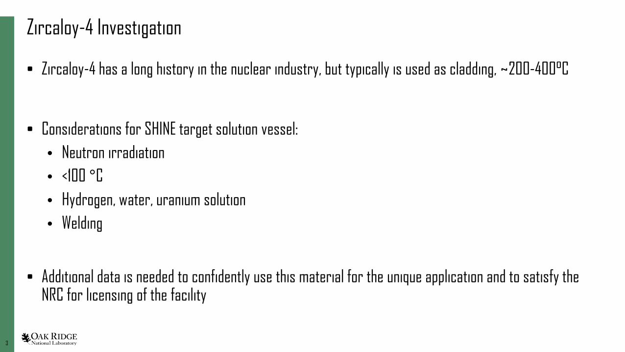
Zircaloy-4 Investigation
• Zircaloy-4 has a long history in the nuclear industry, but typically is used as cladding, ~200-400°C
• Considerations for SHINE target solution vessel:• Neutron irradiation• <100 °C• Hydrogen, water, uranium solution• Welding
• Additional data is needed to confidently use this material for the unique application and to satisfy the NRC for licensing of the facility

44
Preparation of Material
Zircaloy-4 material
Machined bars for welding tests
C. M. Silva, C. D. Bryan. “Evaluation of Zircaloy-4 as the structural material for the Target Solution Vessel and support lines of SHINE — Sample preparation for the third-round neutron irradiation” FY17 Report. ORNL/TM-2017/482

55
Tungsten Inert Gas WeldingBack of root pass Cover pass 1
Burn through on the root sideFinal cover pass
C. M. Silva, C. D. Bryan. “Evaluation of Zircaloy-4 as the structural material for the Target Solution Vessel and support lines of SHINE — Sample preparation for the third-round neutron irradiation” FY17 Report. ORNL/TM-2017/482
• Welding tests performed at Major Tool& Machine Inc.
• ORNL developed a weld quality analysis procedure

66
Post-weld heat treatment-Motivation• Base metal total elongation is ~22-29%• After TIG welding, no post-weld heat treatment, total elongation
is similar to base metal for asymmetric samples (one tab was in the weld and one tab reached the base metal )
• After TIG welding, no post-weld heat treatment, total elongation is ~10-13% for symmetric weld samples
Symmetric weld sample cut location
Asymmetric weld sample cut location
C. M. Silva, C. D. Bryan. “Evaluation of Zircaloy-4 as the structural material for the Target Solution Vessel and support lines of SHINE — Sample preparation for the third-round neutron irradiation” FY17 Report. ORNL/TM-2017/482
77
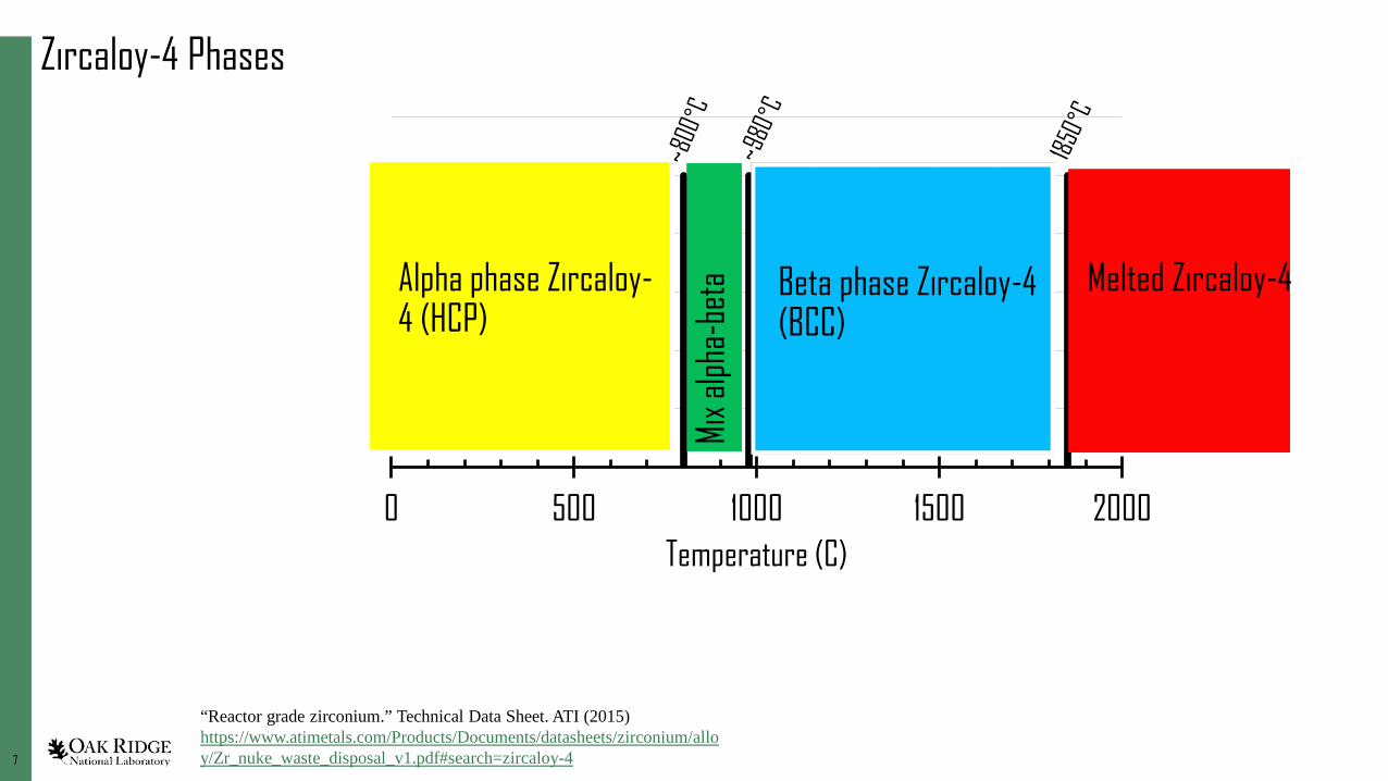
Zircaloy-4 Phases
0 500 1000 1500 2000Temperature (C)
Beta phase Zircaloy-4 (BCC)
Melted Zircaloy-4
Mix a
lpha-
beta
“Reactor grade zirconium.” Technical Data Sheet. ATI (2015) https://www.atimetals.com/Products/Documents/datasheets/zirconium/alloy/Zr_nuke_waste_disposal_v1.pdf#search=zircaloy-4
Alpha phase Zircaloy-4 (HCP)

88
0 500 1000 1500 2000Temperature (C)
Beta phase Zircaloy-4 (BCC)
Melted Zircaloy-4
Mix a
lpha-
beta
Zircaloy-4 Phases
• How weld affects phases and properties
• Ultimate tensile strength decreases
• Yield strength increases
• Total elongation decreases significantly
Weld (melt)Quench
• Locks in some beta phase
C.L. Whitmarsh, Review of Zircaloy-2 and Zircaloy-4 properties relevant to N.S. Savannah reactor design, Oak Ridge National Laboratory, ORNL-3281, (1962)
Alpha phase Zircaloy-4 (HCP)

99
0 500 1000 1500 2000Temperature (C)
Beta phase Zircaloy-4 (BCC)
Melted Zircaloy-4
Mix a
lpha-
beta
Zircaloy-4 Phases
• Annealing affects corrosion and mechanical properties
899-1010°C annealing• Forms significant beta phase• 20-80% increased corrosion in 350°C water or 750°C steam• Tensile total elongation reduced
C.L. Whitmarsh, Review of Zircaloy-2 and Zircaloy-4 properties relevant to N.S. Savannah reactor design, Oak Ridge National Laboratory, ORNL-3281, (1962)
Alpha phase Zircaloy-4 (HCP)

1010
0 500 1000 1500 2000Temperature (C)
Beta phase Zircaloy-4 (BCC)
Melted Zircaloy-4
Mix a
lpha-
beta
Zircaloy-4 Phases
• Annealing affects corrosion and mechanical properties
Annealing below ~800°C• Stays in alpha phase• No change to corrosion rate• Tensile properties can be improved
C.L. Whitmarsh, Review of Zircaloy-2 and Zircaloy-4 properties relevant to N.S. Savannah reactor design, Oak Ridge National Laboratory, ORNL-3281, (1962)
What temperature to use for post weld heat treating?
Alpha phase Zircaloy-4 (HCP)
1111
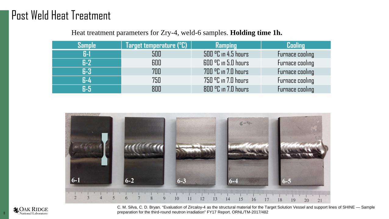
Post Weld Heat Treatment
Sample Target temperature (°C) Ramping Cooling6-1 500 500 °C in 4.5 hours Furnace cooling6-2 600 600 °C in 5.0 hours Furnace cooling6-3 700 700 °C in 7.0 hours Furnace cooling6-4 750 750 °C in 7.0 hours Furnace cooling6-5 800 800 °C in 7.0 hours Furnace cooling
Heat treatment parameters for Zry-4, weld-6 samples. Holding time 1h.
C. M. Silva, C. D. Bryan. “Evaluation of Zircaloy-4 as the structural material for the Target Solution Vessel and support lines of SHINE — Sample preparation for the third-round neutron irradiation” FY17 Report. ORNL/TM-2017/482

1212
Post Weld Heat Treatment
Sample name Cut locationPWHT temp. (°C)
Layer from surface
Ultimate tensile strength (MPa)
Yield stress (MPa)
Total elongation* (%)
ZFA01 SW 500 1 571 442 18.5ZFA02 SW 2 583 468 19.4ZFA03 SW 3 586 468 19.3Average SW 580 459 19ZFB01 SW 600 1 601 488 17.2ZFB02 SW 2 597 489 15.9ZFB03 SW 3 586 476 15.6Average SW 595 484 16ZFC01 SW 700 1 611 504 20.3ZFC02 SW 2 596 485 17.1ZFC03 SW 3 589 480 20.6Average SW 599 490 19ZFD01 SW 750 1 568 477 17ZFD02 SW 2 583 485 16.2ZFD03 SW 3 583 481 20.9Average SW 578 481 18ZFE01 SW 800 1 578 473 21.5ZFE02 SW 2 592 482 20.9ZFE03 SW 3 583 481 19.7Average SW 584 479 21
Heat treatment parameters for Zry-4, weld-6 samples. Holding time 1h.
*TE values are overestimated here from raw data
600°C slightly lower elongation
800°C slightly higher elongation

1313
Post Weld Heat Treatment
SampleLayer from surface
Ultimate tensile strength (MPa)
Yield stress (MPa)
Total elongation (%)
ZGA01, 800C, 12h 1st of 4 588 487 18.1ZGA02, 800C, 12h 2nd of 4 582 489 16.6ZGA03, 800C, 12h 3rd of 4 584 476 17.2ZGA04, 800C, 12h 4th of 4 572 474 17Avg. 582 482 17.2ZGB01, 800C, 24h 1st of 4 581 368 23.6ZGB02, 800C, 24h 2nd of 4 495 428 9.1ZGB03, 800C, 24h 3rd of 4 553 485 12.9ZGB04, 800C, 24h 4th of 4 466 425 8.7Avg. 524 427 13.6ZGC01, 800C, 48h 1st of 4 351 346 17.8ZGC02 800C, 48h 2nd of 4 366 358 10.9ZGC03, 800C, 48h 3rd of 4 352 350 13.7ZGC04, 800C, 48h 4th of 4 495 434 13.4Avg. 391 372 14.0
Heat treatment parameters for Zry-4, weld-7 samples. 800 °C, varied holding times.
consistent
erratic
erratic
*TE values are overestimated here from raw data
Large elongation
Smaller elongation than no post weld heat treatment
C. M. Silva, C. D. Bryan. “Evaluation of Zircaloy-4 as the structural material for the Target Solution Vessel and support lines of SHINE — Sample preparation for the third-round neutron irradiation” FY17 Report. ORNL/TM-2017/482
1414
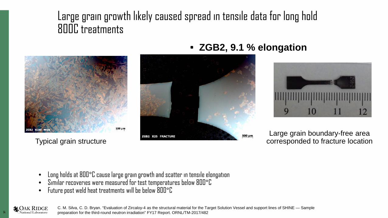
Large grain growth likely caused spread in tensile data for long hold 800C treatments
• ZGB2, 9.1 % elongation
Typical grain structureLarge grain boundary-free area
corresponded to fracture location
• Long holds at 800°C cause large grain growth and scatter in tensile elongation• Similar recoveries were measured for test temperatures below 800°C• Future post weld heat treatments will be below 800°C
C. M. Silva, C. D. Bryan. “Evaluation of Zircaloy-4 as the structural material for the Target Solution Vessel and support lines of SHINE — Sample preparation for the third-round neutron irradiation” FY17 Report. ORNL/TM-2017/482

1515
Hydrogen in Zircaloy-4
• The most significant source of H in reactors is from water corrosion
• Radiolysis of water can also be a source
C.L. Whitmarsh, Review of Zircaloy-2 and Zircaloy-4 properties relevant to N.S. Savannah reactor design, Oak Ridge National Laboratory, ORNL-3281, (1962)

1616
Zircaloy-4 has less H absorption than Zircaloy-2
• Zircaloy-2 (Grade R60802) – Zr– 1.5%Sn– 0.15%Fe– 0.1%Cr– 0.05%Ni
• Zircaloy-4– Zr– 1.5%Sn– 0.2%Fe– 0.1%Cr
C.L. Whitmarsh, Review of Zircaloy-2 and Zircaloy-4 properties relevant to N.S. Savannah reactor design, Oak Ridge National Laboratory, ORNL-3281, (1962)“Reactor grade zirconium.” Technical Data Sheet. ATI (2015)
https://www.atimetals.com/Products/Documents/datasheets/zirconium/alloy/Zr_nuke_waste_disposal_v1.pdf#search=zircaloy-4
Responsible for significant H absorption

1717
Hydrogen effect on mechanical properties
• Hydrogen absorption in Zircaloy is expected to reduce the ductility
• Historical data for Zircaloy-2 shows severe effect above ~100 ppm H
• This must be tested for Zircaloy-4 under low temperature neutron irradiation
C.L. Whitmarsh, Review of Zircaloy-2 and Zircaloy-4 properties relevant to N.S. Savannah reactor design, Oak Ridge National Laboratory, ORNL-3281, (1962)

1818
Hydrogen Charging
• Controlled hydrogen charging is accomplished with heating TiH2 powder in a sealed vacuum tube with Zircaloy-4 samples present
• Samples with different ppm amounts are being produced now for inclusion in the neutron irradiation capsules
C. M. Silva, C. D. Bryan. “Evaluation of Zircaloy-4 as the structural material for the Target Solution Vessel and support lines of SHINE — Sample preparation for the third-round neutron irradiation” FY17 Report. ORNL/TM-2017/482
1919
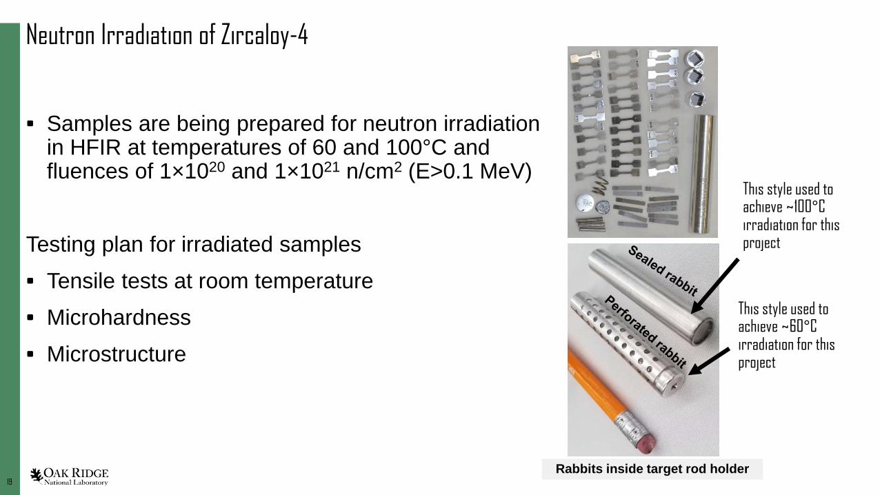
Neutron Irradiation of Zircaloy-4
• Samples are being prepared for neutron irradiation in HFIR at temperatures of 60 and 100°C and fluences of 1×10²⁰ and 1×10²¹ n/cm2 (E>0.1 MeV)
Testing plan for irradiated samples• Tensile tests at room temperature• Microhardness• Microstructure
Rabbits inside target rod holder
This style used to achieve ~100°C irradiation for this project
This style used to achieve ~60°C irradiation for this project
2020
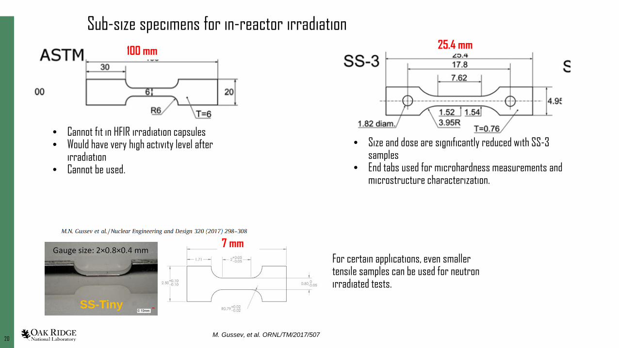
Sub-size specimens for in-reactor irradiation
M. Gussev, et al. ORNL/TM/2017/507
SS-Tiny
• Cannot fit in HFIR irradiation capsules• Would have very high activity level after
irradiation• Cannot be used.
• Size and dose are significantly reduced with SS-3 samples
• End tabs used for microhardness measurements and microstructure characterization.
For certain applications, even smaller tensile samples can be used for neutron irradiated tests.
25.4 mm100 mm
7 mm
2121
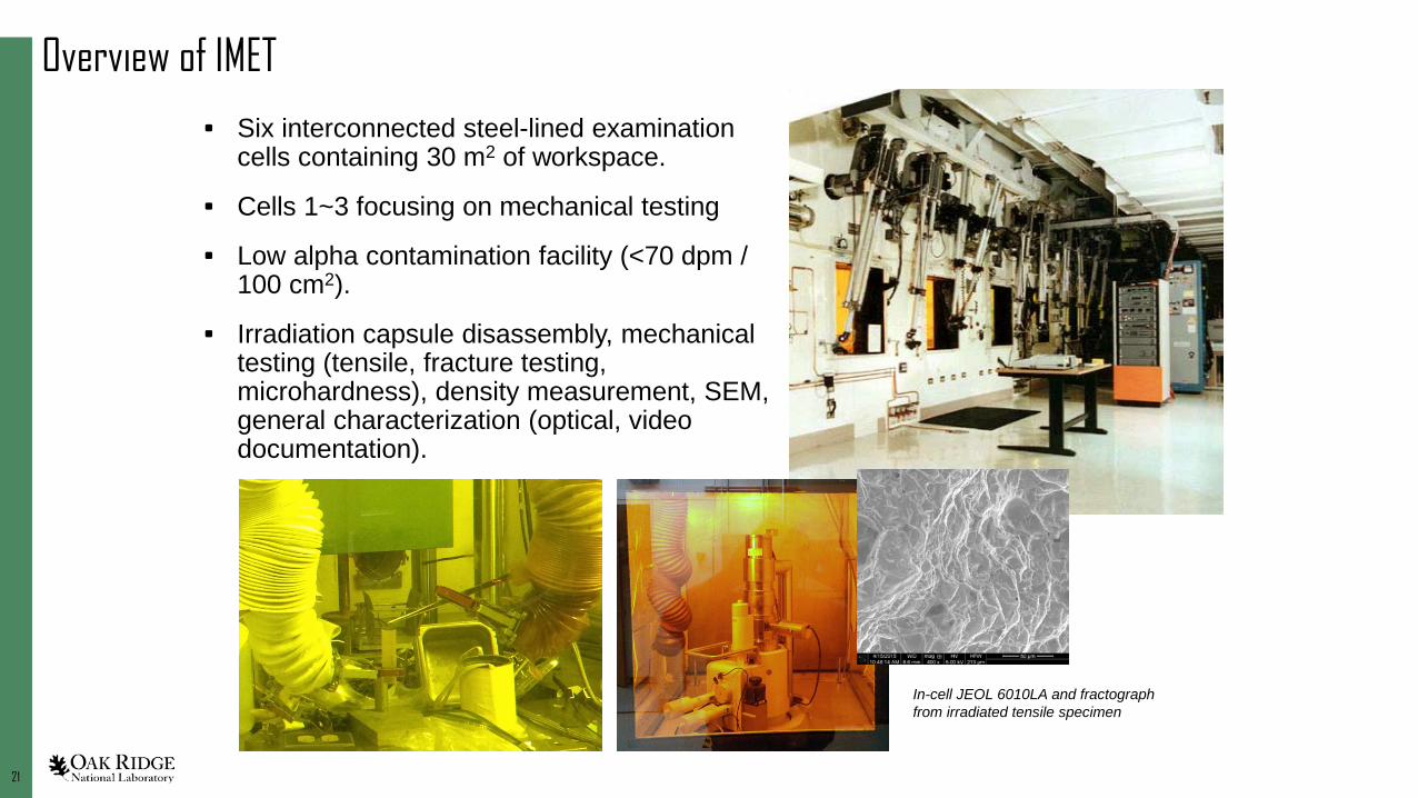
Overview of IMET
• Six interconnected steel-lined examination cells containing 30 m2 of workspace.
• Cells 1~3 focusing on mechanical testing
• Low alpha contamination facility (<70 dpm / 100 cm2).
• Irradiation capsule disassembly, mechanical testing (tensile, fracture testing, microhardness), density measurement, SEM, general characterization (optical, video documentation).
In-cell JEOL 6010LA and fractograph from irradiated tensile specimen

2222
LAMDA: Low Activation Materials Development and Analysis
• Overview– Facility designated for the study of radiological materials by advanced characterization
methods and instruments. – 4327 Sq. Ft of clean lab space and 2732 Sq. Ft of radiological contamination area– ~9000 specimens: fuels, metals, ceramics, graphite
• Specimen acceptance criteria– 100,000 dpm/100cm2 beta/gamma– 2,000 dpm/100cm2 alpha– 100 mR/hr @ 30cm
• Core capabilities– Microstructure characterization– Thermal/physical property– Mechanical testing– Machining irradiated materials– Various specialized instruments

2323
Mechanical property testing instruments• Test Resource 160 series torsion test
machine– 125Nm torsion system– Adjustable speed to 8 rpm
• Tinius Olsen Impact 104– Pendulum impact tester; Charpy or Izod
configuration– 30J capacity– Testing temperatures from -196 to 400°C
• Creep test stands– 1kN load capacity; Air environment– Temperature from -196 to 500°C
• Buehler Wilson VH3100 microhardness tester (10 to 1000g load, programmable)
• Mituyoyo Vickers Microhardness (10 to 2500g load, programmable)
• Agilent Technologies G200 Nano Indentation system
• Sonic velocity measurement system– Measure Young’s and shear moduli with the
sonic velocity methodology according to ASTM C769 and C1419

2424
Microscopes: TEM, FIBs, and SEMHigh-Brightness FEG Electron Source
• 0.96 nm resolution
Available Detectors:• Secondary electrons (ETD
and in-column)• Backscattered electrons
(ETD & concentric)• STEM• Secondary ions
High-Brightness FEG Electron Source
• <1.7 nm resolution
Available Detectors:• Secondary electrons (ETD
and In-Lens)• Retractable annular
Backscattered electron detector
• Extended wavelength cathodoluminescence (CL) detector
• JEOL JEM 2100F Transmission Electron Microscope (FEG, TEM/STEM, EDS, EELS)
• FEI Talos F200X Transmission Electron Microscope (X-FEG, TEM/STEM, super-X EDS)
• XRADIA X-ray Tomography
• Positron Annihilation Spectroscopy
FEI Quanta 3D 200i Dual Beam
FEI Quanta 3D 200i Dual Beam
FEI Versa 3D Hi-Vac Dual Beam
Tescan MIRA3 GMH

2525
Acknowledgements
• This research work was supported by the US Department of Energy’s National Nuclear Security Administration, Office of Material Management and Minimization, Molybdenum-99 Program. This manuscript has been authored by UT-Battelle, LLC, under Contract No. DE-AC05-00OR22725 with the US Department of Energy.
• Thanks to Brian Eckhart, Chris Bryan, Nesrin Cetiner• Also thanks to Maxim Gussev, Xunxiang Hu, Christian M. Petrie, Keith J.
Leonard, Kevin Field, Xiang Chen, Joshua E. Schmidlin, Chad Parish, Philip D. Edmondson, Yutai Katoh


![OXIDATION AND HYDROGEN PICKUP PROPERTIES OF ZIRCALOY ... · integrity of boiling water reactor (BWR) components worldwide [1]. Typical structural materials are austenitic stainless](https://img.pdfslide.us/doc/110x75/5fa26db49a422f0bcb633eb9/oxidation-and-hydrogen-pickup-properties-of-zircaloy-integrity-of-boiling-water.jpg)