Embed Size (px)
Citation preview
Using Zigzag Transformers with Phase-shift to reduce Harmonics in AC-DC Systems
H. K. Høidalen, R. Sporild
Abstract-- In large industry production facilities, twelve pulse rectifier units are often used for the conversion to DC-current. In order to improve the harmonic signature from the plant versus the grid, several transformer units are internally phase-displaced by means of combined couplings involving Z-arrangement. This paper outlines how such a transformer is modelled in ATP both as a Saturable Transformer component and as a coupled RL-matrix. An actual industrial plant with 5 12-pulse rectifying units in parallel is modelled with 6º phase displacement. The analysis of the harmonic content of the supplying current shows that this arrangement is equivalent to a 60-pulse system only in the case of perfect symmetry in the system. Measurements show that the 3rd, 5th , 7th, 11th, and 13th harmonics easily exceed the theoretical 59th and 61st harmonics.
Keywords: Saturable transformer, melting furnace, diode rectifiers, harmonics, phase-shift, zigzag, test report, ATPDraw.
I. NOMENCLATURE The zigzag winding is characterized by the following
parameters: U1 Voltage across the two winding parts U1z Voltage across the z-part U1y Voltage across the y- part n Ratio between U1y and U1z α Phase-shift related to a Y-winding L1z Inductance in the z-part in [H] or [pu] R1z Resistance in the z-part in [Ω] or [pu] L1y Inductance in the y-part in [H] or [pu] R1y Resistance in the y-part in [Ω] or [pu]
II. INTRODUCTION n the power supply to large industrial plants involving AC-DC converters, power quality is a problem. The current on
the AC-side contains harmonics of the order k⋅n±1, where k is the number of pulses in the rectifying bridge and n=1, 2… Filters on the high voltage AC side are expensive and alternative solutions are often beneficial. When several AC-DC converters are installed in parallel, power transformers with different phase-shifts can be used to cancel out the H. K. Høidalen is with The Norwegian University of Science and Technology, Dept. of Electrical Power Engineering, N-7491 Trondheim, Norway (e-mail: [email protected]). R. Sporild is with ABB AS Norway, Automation Technologies Division, P.O.Box 6540 Rodeløkka, N-0501 Oslo, Norway (e-mail: [email protected]). Presented at the International Conference on Power Systems Transients (IPST’05) in Montreal, Canada on June 19-23, 2005 Paper No. IPST05 - 44
harmonic currents. In a particular industrial plant in Sunndalsøra-Norway five 12-pulse AC-DC converters are installed in parallel with phase shifts -12º, -6º, 0º, +6º, and +12º, which results in an equivalent 60-pulse system.
A zigzag coupling on the primary side and two secondary sides with 30 degrees internal phase shift supplying a 12-pulse rectifying bridge is investigated in this paper. The modeling of zigzag transformers with the saturable transformer components in ATP [1] is reported in [2, 3]. In the present paper the analysis in [2] is extended to the case of an arbitrary phase shift of <-60,0> and <0,60> degrees based on [4].
III. MODELING OF ZIGZAG WINDING In this section the zigzag winding is modeled both
according to the saturable transformer component in ATP and as a more general coupled RL-matrix formulation.
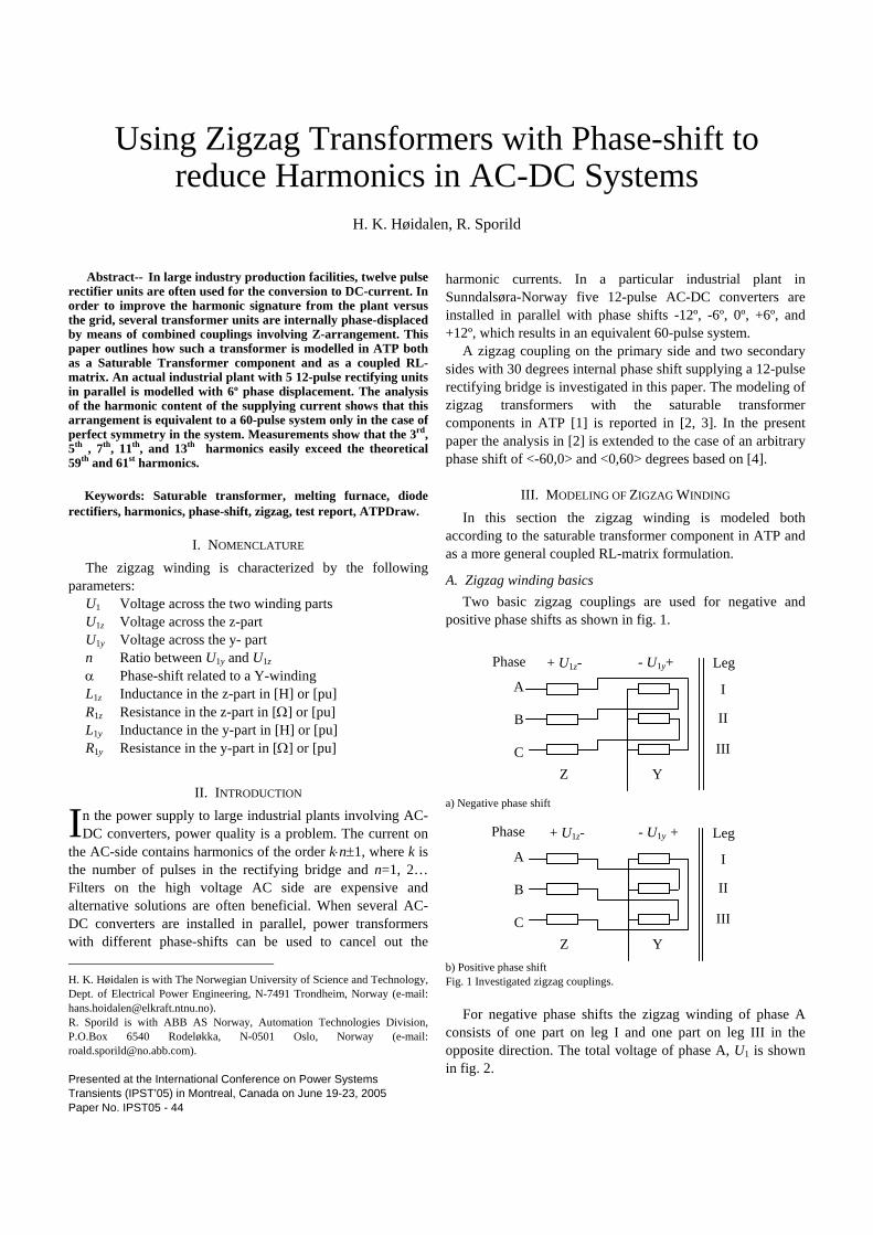
A. Zigzag winding basics Two basic zigzag couplings are used for negative and
positive phase shifts as shown in fig. 1.
a) Negative phase shift
b) Positive phase shift Fig. 1 Investigated zigzag couplings.
For negative phase shifts the zigzag winding of phase A consists of one part on leg I and one part on leg III in the opposite direction. The total voltage of phase A, U1 is shown in fig. 2.
I
Leg
Z Y
+ U1z- - U1y+
I
II
III
A
B
C
Phase
Z Y
+ U1z- - U1y +
I
II
III
Phase Leg
A
B
C

Fig. 2 Voltages of the zigzag winding of phase A. Negative phase shift.
The absolute values of the phase voltages of each winding part are
)60sin(
)sin(
1
1
αα−
==z
y
UU
n (1) (1)
)60cos()cos(
|||| 11 αα −⋅+
=nUU z (2)
)60cos()cos(
|||| 1
1 α−⋅+α⋅
=n
nUU y (3)
with α equal to the absolute value of the phase shift. The voltage vectors are
601
11 −∠⋅+
=n
UU z and 601601
1 −∠⋅+−∠⋅
=nnUU y (4)
The same equations apply to the positive phase shift case.
B. The Saturable Transformer approach This section outlines how to model a zigzag winding
compatible with the saturable transformer model in ATP [1]. The short circuit and magnetizing characteristics are handled along with the zero-sequence behavior.
The winding resistance, the leakage inductance, and the magnetizing impedance of the total zigzag winding are now divided in two parts as illustrated in fig. 3.
a) Short circuit b) Open circuit Fig. 3 Distribution of the short-circuit and open-circuit impedances. Positive sequence, negative phase shift.
The total short-circuit resistance and inductance as
obtainable from measurements are yz RRR 111 += and
yz LLL 111 += respectively as shown in fig. 3a). The winding
resistance is proportional to the number of windings turns while the leakage inductance is proportional to the square of this number. Since the winding voltages Uz and Uy are proportional to the number of turns this gives zy RnR 11 ⋅= and
zy LnL 12
1 ⋅= . As a result
nnR
Rn
RR yz +
⋅=∧
+=
111
11
1 [Ω] (5)
2
21
121
1 11 nnLL
nLL yz +
⋅=∧
+= [H] (6)
The total magnetizing impedance as obtainable from
measurements is mm IUZ /1= . According to fig. 3b) the magnetizing current in the two winding parts is
ymy
ymz
mz
zm I
ZU
IIZUI +
−=−∠−∧+= 11 120 (7)
When the transformer is unloaded 0=⋅+ nII yz . From this (7) can be reformulated as
my
y
mz
zm Z
Un
ZU
nI 11)1201( ⋅−=−∠−⋅ (8)
Inserting (4) into (8) gives after some manipulation
⎟⎟⎠
⎞⎜⎜⎝
⎛ −∠−⋅
++=
mymzm Z
nZnn
UI 601
1
2
21 (9)
The magnetizing inductance is proportional to the square of
the number of windings, mzmy LnL ⋅= 2 . If the magnetizing
impedance is assumed to be purely inductive the total measurable apparent magnetizing inductance is
)/(1 mm IjUL ω= , where U1 is the phase voltage. The absolute value is taken since a phase shift in the magnetizing current will be introduced in the zigzag winding. From (9) the magnetizing inductances in each winding part are obtained
22 11|601|
nnL
nnLL mm
mz++
=++
−∠−⋅= (10)
2
2
1 nnnL
L mmy
++
⋅= (11)
In the saturable transformer model in ATP a magnetizing branch is added to the primary winding only. In this case Zmy in (9) must be set to infinity. This results in
21 nnL
L mATPmz
++= (12)
The zero sequence reluctance can similarly to the
magnetizing inductance be found from fig. 3b). In this case the current mII =0 in phase B on leg I is equal in amplitude,
U1z
U1y
U1
α
60-α
I
II III
R1z L1z Phase A
III
R1y L1y
+ Uz -
-
120∠yU+
I
N
Lm
+ Uz
- Uy +
Phase A
I Phase B
Lm
120−∠mI
Im Iz
Iy

but opposite in phase to the current in phase A. This also applies to voltages across the two winding parts, so that
00 zy UnU ⋅−= and 1000 UUU yz =+ . The relationship
000 =⋅+ nII yz is still valid. This gives
⎟⎟⎠
⎞⎜⎜⎝
⎛+⋅
−=−
⇒+−
=−∧+=
yz
yy
yz
z
z
Zn
ZnU
nI
IZU
IIZU
I
0
2
0
100
00
000
0
00
11
)1( (13)
The zero sequence impedance is mostly inductive and for a 3-leg core mostly linear. The zero sequence inductance is proportional to the square of the number of windings. This gives
( ) ( )2
2
0
1002
0
100
12
12
nn
IU
LnI
UL yz
−
⋅⋅
⋅ω=∧
−⋅
⋅ω= (14)
The saturable transformer component in ATP supports only a zero-sequence reluctance in the primary winding. In this case Z0y is infinite and
( )2
0
100
11nI
ULATP
z−
⋅⋅ω
= (15)
The reluctance specified in ATP is 02
0 3/ LUR = where U is the voltage across the winding where the reluctance is connected. This gives
33
100
0
20
0UI
LU
R ATPz
z ⋅⋅ω=
⋅= (16)
The Saturable transformer formulation for zigzag windings is supported directly by ATPDraw 4 [3].
C. Coupled RL-Matrix Formulation The zigzag transformer can also be modeled as coupled
inductance and resistance matrices based on the standard star equivalent in the per unit system as shown in fig. 4. Fig. 4. Basic Star-equivalent Fig. 5a. Modified Star-equivalent, positive sequence
Fig. 5b. Modified Star-equivalent, zero sequence
The zigzag impedances in fig. 5 are calculated from (5) and (6) scaled by the square of the voltage ratios to obtain a common per unit basis. This gives with R1 and L1 in [pu]:
][/
1
][1
)1(1
121
211
1
21
21
211
1
punRUU
nnRR
pun
nnRUU
nRR
zy
y
zz
=⋅+⋅
=
+++⋅
=⋅+
=
(17)
][
1
][1
)1(1
121
21
2
2
1
2
21
21
21
21
1
puLUU
nnLL
pun
nnLUU
nLL
zy
y
zz
=⋅+⋅
=
+++⋅
=⋅+
=
(18)
The formulation of inductance and resistance matrices will be outlines here, since this is the approach used by SIMSEN [4]. From the modified per unit star-equivalents in fig. 5 the inductance matrices in positive and zero sequence systems are
⎥⎥⎥⎥
⎦
⎤
⎢⎢⎢⎢
⎣
⎡
++
+
=mmm
mmzm
mmmy
P LLLLLLLLLLLL
L2
1
1
(19)
⎥⎥⎥⎥
⎦
⎤
⎢⎢⎢⎢
⎣
⎡
++
+
=0200
0010
0001
LLLLLLLLLLLL
L z
y
Z (20)
The total inductance matrix is
⎥⎥⎥⎥
⎦
⎤
⎢⎢⎢⎢
⎣
⎡
=Txx
xyTx
xxzT
LLLLLLLLL
L2
1
1
(21)
The resistance matrix is diagonal with equal zero and
positive sequence parameters
⎥⎥⎥⎥
⎦
⎤
⎢⎢⎢⎢
⎣
⎡
==2
1
1
000000
RR
R
RR y
z
ZP (22)
Each matrix element in (21) and (22) consists of a 3x3 sub-
matrix on the standard form
R1+jωL1
jωLm
U1 U2 : Un
R2+jωL2
U1y U2 : Un U1z
R2+jωL2 R1y+jωL1y
R1y+jωL1y jωLm
U1y U2 : Un U1z
R2+jωL2 R1y+jωL1y
R1y+jωL1y jωL0

⎥⎥⎥
⎦
⎤
⎢⎢⎢
⎣
⎡=
SMM
MSM
MMS
ij
ZZZZZZZZZ
Z (23)
with )2(31
PiiZiiSii ZZZ +⋅= and )(31
PijZijMij ZZZ −⋅=
The on- and off-diagonal elements in (21) are
⎥⎥⎥
⎦
⎤
⎢⎢⎢
⎣
⎡
++−−−++−−−++
⋅=
000
000
000
2323
23
31
LLLLLLLLLLLLLLLLLLLLL
L
mimm
mmim
mmmi
iT (24)
⎥⎥⎥
⎦
⎤
⎢⎢⎢
⎣
⎡
+−−−+−−+
⋅=
mmm
mmm
mMm
x
LLLLLLLLLLLLLLLLL
L2
22
31
000
000
00
(25)
To obtain the final inductance and resistance matrices each
row and column in (21) and (22) are multiplied with the winding voltage and all elements are divided with the rated power as outlined in the EMTP TheoryBook [5].
IV. CASE STUDY
This section outlines in details how to model a 3-winding transformer based on the test report and the result of using it to supply five 12-pulse rectifying bridges in parallel.
A. Test Report Table I shows the test report in the case of a -12º phase
shift. Similar data appear for the other phase shifts (-6º, 0º, +6º, +12º). The short circuit resistances are very low and contain only one significant digit. This will introduce some inaccuracies in the calculations.
TABLE I
TEST REPORT DATA Coupling: ZN0d11yn0 Rated power: 115 MVA Rated primary voltage: 85.92 kV Rated secondary voltage ∆: 1.218 kV Rated tertiary voltage Y: 1.230 kV Rated frequency: 50 Hz Open circuit current: 0.005 pu Short circuit impedance 1-2: 0.004 + j0.085 pu Short circuit impedance 1-3: 0.004 + j0.085 pu Short circuit impedance 2-3: 0.01 + j0.158 pu Phase shift Z (ref. 3): -12 deg.
The standard per unit equivalent circuit for the short circuit
impedances is shown in fig. 6. Table II shows the calculated winding voltages, resistances
and leakage inductances based on (2-3) and (5-6). These values are used directly in the Saturable Transformer component of ATP. The secondary and tertiary voltages are not exactly equal and this will introduce the 6·(2n-1)±1 harmonics. The difference is due to the very low number of
turns (<10) on the DC sides. This is partly compensated by transducers located between the transformer and rectifier. Since only 6 digits are available in the ATP-format for the values in Table II the resistances must be specified with care as shown in fig. 7.
Fig. 6 Per unit equivalent circuit
TABLE II TRANSFORMER EQUIVALENT, PHASE SHIFT -12 º
Winding U [kV] R [mΩ] L [mH] 1z 73.73 -50.2 1.136 1y 20.64 -14.0 0.0891 2D 2.11 0.193 0.00973 3Y 1.23 0.066 0.00331
If the HV winding 1 is chosen as the primary winding, the
magnetizing branch will be added to the first winding part (Z) of the zigzag winding. Alternatively the magnetizing branch should be added to the low-voltage Y-coupled winding. This could be done externally or by choosing winding 2 or 3 as the primary. The magnetizing branch added to winding 1 should be calculated from (12). The measured inductance is
( ) ][H 9.40MVA 115/ kV92.580.637
pu 0.637pu005.0502
1
2 =⋅=
=⋅⋅
=πmL
and the inductance that should be added to winding 1Z in ATP:
[H] 1.031 2 =
++=
nnL
L mATPmz
As a starting point the zero-sequence inductance L0 is set to zero. This corresponds to an infinite zero-sequence reluctance, ref. (16) and fig. 5b. In fig. 7 a 3-leg core is checked and this enables the Transformer Three Phase model in ATP. However, when the zero-sequence reluctance R0 is infinity this is equivalent to the standard Saturable Transformer component.
Fig. 7. Data input in to the Saturable transformer model in ATPDraw. The magnetization is specified as i= 1A and λ=30.1 Wb-T.
[pu]j0.0790.0052/)(
[pu]j0.0790.0052/)(
[pu]j0.0060.0012/)(
1223133
1323122
2313121
+=−+=
+=−+=
+−=−+=
ZZZZ
ZZZZ
ZZZZ1 2
3
Z1 Z2
Z3

B. Comparison between the Saturable Transformer and the RL-Matrix Formulation The matrix formulation results in a 12x12 coupled RL-
matrix. The input impedance of the high voltage side is calculated as a function of frequency and the absolute value is shown in fig. 8. The impedances of the two types of models are practically identical. As the frequency approaches zero all the impedances will reach the negative resistance -0.064 Ω. This is not a physically correct result however, and is due to the artificial star-point introduced in the models as shown in of fig. 4-5. Instability as discussed in [6] due to the negative resistance was not observed in this study. An alternative to the two equivalent types of models is the admittance approach used in BCTRAN [1, 5]. As long as the test report only gives information about the total zigzag winding (with phase shift) it is not straight forward to avoid the negative impedance. An argument against the RL-matrix formulation is that the accuracy is limited by the large difference between magnetizing and short circuit inductances [5]. To reduce this problem, high resolution (16 digits) is used in this study. The accuracy is in this case not a problem compared to the Saturable transformer model with only 6 digits available for the short circuit impedances.
Fig. 8. Input impedance at the high-voltage side (zigzag) of the transformer models, phase shift -12º. Open and short circuit positive sequence and open circuit zero sequence.
C. Simulation of five parallel 12-pulse rectifying groups This example is based on a practical situation in an
industrial plant in Norway. Five 12-pulse rectifying (diode) groups are installed in parallel as shown in fig. 9. From the 132 kV side the 5 units are supplied by regulating transformers feeding the rectifying transformers and adjusted to 132/82.5 kV for nominal load. Three situations are simulated and the harmonic content of the phase current on the 132 kV side is calculated • without phase-shift between the five transformers, Ydy • with a 6º phase shift between the five (0º, ±6º, ±12º), Zdy • same as above, but the secondary voltage is adjusted from
1.218 to 1.23 kV, Zdmy Figure 10 shows that 5 phase shifting transformer units in
parallel reduce the content of the 12n±1 harmonics up to 2 decades. The 6·(2n-1)±1 harmonics are much less reduced. Adjusting the secondary voltage from 1.218 to 1.23 kV to obtain perfect symmetry between the secondary and tertiary windings will have a significant effect on all 6n±1 harmonics up to 59 and 61 resulting in an equivalent 60 pulse system.
132 kV
5 uH
.027 ohm
1 mF
22.2 m H
Zdy
Zdy
Zdy
Zdy
Zig-zagtrans formersZN0d11y085.9/1.21 kV
-12
-6
+6
+12
Ydy
Regulatingtransformers132/82.5 kV
Fig. 9. Circuit in ATPDraw for simulation of five parallel 12-pulse rectifying groups. The transformer with 0º phase shift is coupled Ydy. The nominal DC current and voltage from each rectifier is 55 kA and 1.5 kV. The snubbers of the diode rectifiers are set to C=9 µF in series with R=1.5 Ω with reference to [7]. The regulating transducers between transformer and rectifier ignored.
0,00001
0,0001
0,001
0,01
0,1
1
10
100
1 5 7 11 13 17 19 23 25 29 31 35 37 41 43 47 49 53 55 59 61 THD
Harm onics
Har
mon
ic c
onte
nt [%
]
Ydy
Zdy
Zdmy
Fig. 10. Harmonic content of the primary side current, phase A in [%]. Obtained by PlotXY[8]. Ydy: no phase shift, Zdy: 6º phase shift, Zdmy: 6º phase shift and adjusted secondary voltage from 1.218 to 1.23 kV. All other harmonics than those shown in fig. 10 are insignificant. Time step ∆t=1 µs.
The industry process in fig. 9 allows the loss of up to 2
rectifying groups. The total harmonic distortion (THD) increases from the nominal value 1.13 % to 1.72 % and 2.79 % when one and two groups are disconnected, respectively before regulation of the applied voltage.
0.0 0.5 1.0 1.5 2.0 2.5 3.0 3.5
Log(f)0.1
10
1000
105
Z[Ω] Z+ open Z+ short Z0 open
107
4.0
Tab.III current
Fig. 10 current

V. COMPARISON WITH MEASUREMENTS The current on the 132 kV side into rectifier group 1 (-12º
phase shift) was also measured. The regulating transformers were adjusted to a 132/52 kV ratio resulting in 0.94 kV and 55 kA in the 0.017 Ω DC load. The filters were disconnected during the measurements. Table III shows substantial differences between the measurements and the calculation, except for the most important 11th and 13th harmonics. The 1st and the 3rd harmonics are higher in the measurements while the 5th and 7th harmonics are higher in the calculations. The THD is measured as 5.74% and calculated as 6.56 %. The content of 2nd and 3rd harmonics obtained from the measurements can originate from the 132 kV supply, but these harmonics are typically caused by saturation effects ignored in the simulations. Also nonlinearities in the current transformers used in the measurements can cause lower order harmonics. The lower content of 5th and 7th harmonics in the measurements can be due to the regulating transducer on the secondary side ignored in the simulations.
TABLE III
CALCULATED AND MEASURED HARMONICS OF 132 KV SIDE CURRENT INTO RECTIFYING GROUP 1 IN [A]RMS .
Harm. Meas. Calc. Harm. Meas. Calc. 1 266.3 246.8 19 0.60 0.86 2 0.47 0.00 23 1.00 2.01 3 1.53 0.00 25 0.90 1.48 4 0.30 0.00 29 0.00 0.68 5 3.03 5.89 31 0.00 0.58 7 1.90 3.29 35 0.43 0.84 9 0.50 0.00 37 0.53 0.67 11 12.17 12.33 41 0.20 0.44 13 8.17 7.32 43 0.10 0.38 15 0.27 0.00 47 0.10 0.36 17 0.80 1.13 49 0.00 0.30
VI. CONCLUSIONS Modeling of zigzag transformers using the SATURABLE
TRANSFORMER component in ATP and a general coupled RL-matrix formulation is presented in this paper. Formulas for the ratios of voltage, resistance and leakage inductance between the two parts of a zigzag winding are presented. Magnetization and the zero-sequence are briefly outlined. The two types of models have identical characteristics in the frequency domain. The saturable transformer approach is well suited for standard modeling and a nonlinear magnetizing branch can easily be added (scaled as in (12)). The matrix formulation enables a more sophisticated zero-sequence modeling.
An example shows how to obtain a model for a three-winding transformer with zigzag on its primary. The example shows how five parallel 12-pulse rectifying groups become an equivalent 60-pulse system seen from the HV-side when a
phase shift of 6º is introduced between five perfectly balanced zigzag coupled transformers. Changes from the ideal balanced situation will rapidly introduce 3rd, 5th, 7th, 11th, and 13th harmonics, however. The results confirm a considerable reduction in THD due to the phase-shift arrangement. This in turn contributes to a simplified and cheaper filter arrangement as compared to the ordinary 12-pulse converters.
Comparing calculations to measurement shows substantial deviations. Only the most significant harmonics can be predicted accurately. Detailed modelling of the voltage supply, transformer magnetization, regulating mechanisms, and the DC load characteristics is required to calculate the other harmonics with accuracy.
VII. REFERENCES [1] Alternative Transients Program (ATP) - Rule Book, Canadian/American
EMTP User Group, 1987-1998. [2] P. Riedel: “Modelling of zigzag-transformers in the three-phase system,”
presented at the EMTP Users group meeting, Marseille, France, May 28-29, 1990.
[3] H. K. Høidalen, R. Sporild, “Modeling of phase-shift zigzag transformers in ATP,” presented at the EEUG meeting, Trondheim, Norway, Oct. 3-5, 2004.
[4] A. Sapin, P. Allenbach, J. J. Simond, “Modeling of multi-windings phase shifting transformers for DC supplies,” presented at ICEM 2000, Helsinki, Finland.
[5] H. Dommel, “Electromagnetic transient program reference manual - EMTP Theory Book,” Bonneville Power Administration, 1986.
[6] T. Henriksen, "How to avoid unstable time domain responses caused by transformer models," IEEE Trans. Power Delivery, vol. 17, pp. 516-522, Apr. 2002.
[7] T. Undeland, A. Petterteig,G. Hauknes, A. K. Ådnanes, S. Garberg, “Diode and thyristor turn-off snubbers – Simulation by KREAN and an easy to use algorithm ,” Proc. Of the Industry application society annual meeting, 2-7 Oct. 1988, pp. 647-654, Conference record of the 1988 IEEE.
[8] M. Ceraolo, “Get a clear view of simulated and measured data,” Computer Applications in Power, IEEE, vol. 13, Issue. 4, Oct. 2000 Pages:36 – 42.
VIII. BIOGRAPHIES
Hans Kristian Høidalen was born in Drangedal, Norway in 1967. He received the M. S. and PhD degrees from the Norwegian Institute of Technology in 1990 and 1997, respectively. He is now an associate Professor at the Norwegian University of Science and Technology. His special field of interest is computation of electromagnetic stresses.
Roald Sporild was born in Trondheim, Norway in 1965. He received the M. S. degree from the Norwegian Institute of Technology in 1990. He is now engaged by ABB AS Norway as an Senior Electrical Engineer performing power system calculations.