Embed Size (px)
DESCRIPTION
Brushless DC motor Magnetic Field Distributions
Citation preview
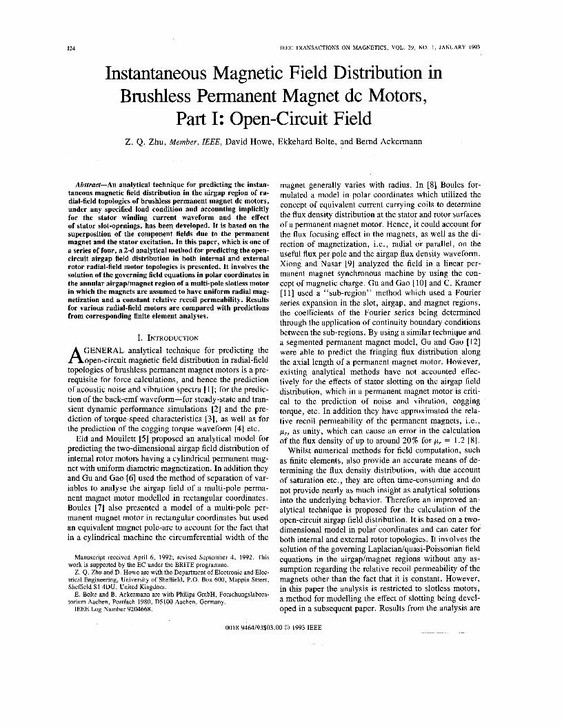
I24 IEEE TRANSACTIONS ON MAGNETICS, VOL. 29, NO. 1, JANUARY 1993
Instantaneous Magnetic Field Distribution in Brushless Permanent Magnet dc Motors,
Part I: Open-circuit Field Z. Q. Zhu, Member, ZEEE, David Howe, Ekkehard Bolte, and Bemd Ackermann
Abstract-An analytical technique for predicting the instan- taneous magnetic field distribution in the airgap region of ra- dial-field topologies of brushless permanent magnet dc motors, under any specified load condition and accounting implicitly for the stator winding current waveform and the effect of stator slot-openings, has been developed. It is based on the superposition of the component fields due to the permanent magnet and the stator excitation. In this paper, which is one of a series of four, a 2-d analytical method for predicting the open- circuit airgap field distribution in both internal and external rotor radial-field motor topologies is presented. It involves the solution of the governing field equations in polar coordinates in the annular airgaplmagnet region of a multi-pole slotless motor in which the magnets are assumed to have uniform radial mag- netization and a constant relative recoil permeability. Results for various radial-field motors are compared with predictions from corresponding finite element analyses.
I. INTRODUCTION GENERAL analytical technique for predicting the A open-circuit magnetic field distribution in radial-field
topologies of brushless permanent magnet motors is a pre- requisite for force calculations, and hence the prediction of acoustic noise and vibration spectra [ 11; for the predic- tion of the back-emf waveform-for steady-state and tran- sient dynamic performance simulations [2] and the pre- diction of torque-speed characteristics [3], as well as for the prediction of the cogging torque waveform [4] etc.
Eid and Mouilett [5] proposed an analytical model for predicting the two-dimensional airgap field distribution of internal rotor motors having a cylindrical permanent mag- net with uniform diametric magnetization. In addition they and Gu and Gao [6] used the method of separation of var- iables to analyse the airgap field of a multi-pole perma- nent magnet motor modelled in rectangular coordinates. Boules [7] also presented a model of a multi-pole per- manent magnet motor in rectangular coordinates but used an equivalent magnet pole-arc to account for the fact that in a cylindrical machine the circumferential width of the
Manuscript received April 6 , 1992; revised September 4 , 1992. This work is supported by the EC under the BRITE programme.
Z. Q . Zhu and D. Howe are with the Department of Electronic and Elec- trical Engineering, University of Sheffield, P.O. Box 600, Mappin Street, Sheffield S1 4DU, United Kingdom.
E. Bolte and B. Ackermann are with Philips GmbH, Forschungslabora- torium Aachen, Postfach 1980, D5100 Aachen, Germany.
IEEE Log Number 9204668.
magnet generally varies with radius. In [8] Boules for- mulated a model in polar coordinates which utilized the concept of equivalent current carrying coils to determine the flux density distribution at the stator and rotor surfaces of a permanent magnet motor. Hence, it could account for the flux focusing effect in the magnets, as well as the di- rection of magnetization, i.e., radial or parallel, on the useful flux per pole and the airgap flux density waveform. Xiong and Nasar [9] analyzed the field in a linear per- manent magnet synchronous machine by using the con- cept of magnetic charge. Gu and Gao [lo] and C. Kramer [ 111 used a “sub-region” method which used a Fourier series expansion in the slot, airgap, and magnet regions, the coefficients of the Fourier series being determined through the application of continuity boundary conditions between the sub-regions. By using a similar technique and a segmented permanent magnet model, Gu and Gao [12] were able to predict the fringing flux distribution along the axial length of a permanent magnet motor. However, existing analytical methods have not accounted effec- tively for the effects of stator slotting on the airgap field distribution, which in a permanent magnet motor is criti- cal to the prediction of noise and vibration, cogging torque, etc. In addition they have approximated the rela- tive recoil permeability of the permanent magnets, Le., p,, as unity, which can cause an error in the calculation of the flux density of up to around 20 % for p, = 1.2 [8].
Whilst numerical methods for field computation, such as finite elements, also provide an accurate means of de- termining the flux density distribution, with due account of saturation etc., they are often time-consuming and do not provide nearly as much insight as analytical solutions into the underlying behavior. Therefore an improved an- alytical technique is proposed for the calculation of the open-circuit airgap field distribution. It is based on a two- dimensional model in polar coordinates and can cater for both internal and external rotor topologies. It involves the solution of the governing Laplaciadquasi-Poissonian field equations in the airgap/magnet regions without any as- sumption regarding the relative recoil permeability of the magnets other than the fact that it is constant. However, in this paper the analysis is restricted to slotless motors, a method for modelling the effect of slotting being devel- oped in a subsequent paper. Results from the analysis are
0018-9464/93$03.00 0 1993 IEEE
-
ZHU el 01.: MAGNETIC FIELD DISTRIBUTION IN BRUSHLESS PERMANENT MAGNET DC MOTORS, PART I.
compared with predictions from corresponding finite ele- ment analyses of various radial-field motors.
11. MAGNETIC FIELD PRODUCED BY MAGNETS A. General Equations In Polar Coordinates
In this section general expressions are derived, in terms of polar coordinates, for the magnetic field produced by the permanent magnets in both extemal and internal rotor topologies of slotless motors having surface-mounted magnet rotors. The modifying effect of stator slotting is accounted for subsequently in part I11 [ 141.
and H are coupled by The field vectors -+ -+
B, = poHl in the airspaces; (1)
BII = pm HIl + p o M in the permanent magnet (2)
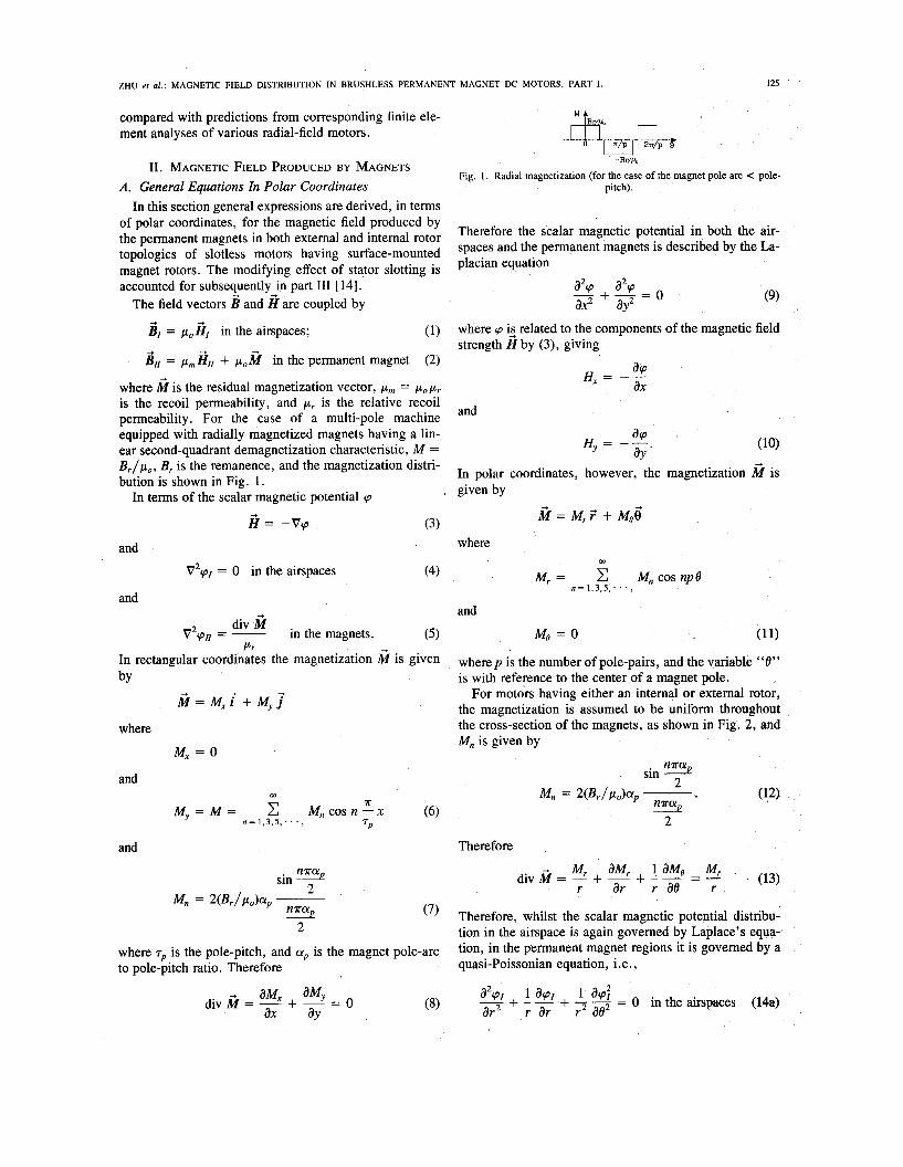
where M is the residual magnetization vector, pm = p o p r is the recoil permeability, and p , is the relative recoil permeability. For the case of a multi-pole machine equipped with radially magnetized magnets having a lin- ear second-quadrant demagnetization characteristic, M = B , / p , , B, is the remanence, and the magnetization distri- bution is shown in Fig. 1.
-+ -+ -+
-+
In terms of the scalar magnetic potential cp -+
H = -Vp (3)
and
v2cp1 = o in the airspaces (4)
and
in the magnets. (5) div M v2cp, = -
P r In rectangular coordinates the magnetization $f is given by
-+ 2 = ~ , i + M~ j
M, = 0 where
and m
and
125
-Br%
Fig. 1 . Radial magnetization (for the case of the magnet pole arc < pole- pitch).
Therefore the scalar magnetic potential in both the air- spaces and the permanent magnets is described by the La- placian equation
(9)
where cp @ related to the components of the magnetic field strength H by (3), giving
acp ax
H = --
and
In polar coordinates, however, the magnetization M is given by
M=M, .T + M e 6
where m
M, = C M, COS np8 n = 1,3,5, ‘ . . ,
and
Me = 0 (11)
wherep is the number of pole-pairs, and the variable “e” is with reference to the center of a magnet pole.
For motors having either an internal or extemal rotor, the magnetization is assumed to be uniform throughout the cross-section of the magnets, as shown in Fig. 2, and Mn is given by
sin
Therefore
-+ M, aMr 1 aMe M, 2~ r ar r a0 r ’ (13) sin 5
Mn = 2(Br/Pobp ___
d i v M = - + - + -- = -
map 2 - (7) Therefore, whilst the scalar magnetic potential distribu-
tion in the airspace is again governed by Laplace’s equa- tion, in the Permanent magnet regions it is governed by a quasi-Poissonian equation, i.e.,
where T~ is the pole-pitch, and ap is the magnet pole-arc to pole-pitch ratio. Therefore
-+ aM, aMy ax ay
div M = - + - = 0 1 +I 1 a d (‘1 G r ar r2 ae a2p1 + - - + - 7 = 0 in the airspaces (14a)
126 IEEE TRANSACTIONS ON MAGNETICS, VOL. 29, NO. 1, JANUARY 1993
and substituting into (18), the constant C1 is obtained as
1 Mn (20)
- 1 pr c1 = - (np)2
Therefore m
r cos npe. (21)
However this solution is not valid for the particular case of np = 1. Hence for np = 1, by letting r = e' , (18) becomes :
% + - = - e a2vII M I cos6
Mn pi1 =
n = 1 , 3 , 5 , . . . , pr[l - (np) 1
(22) at2 ae2 p,
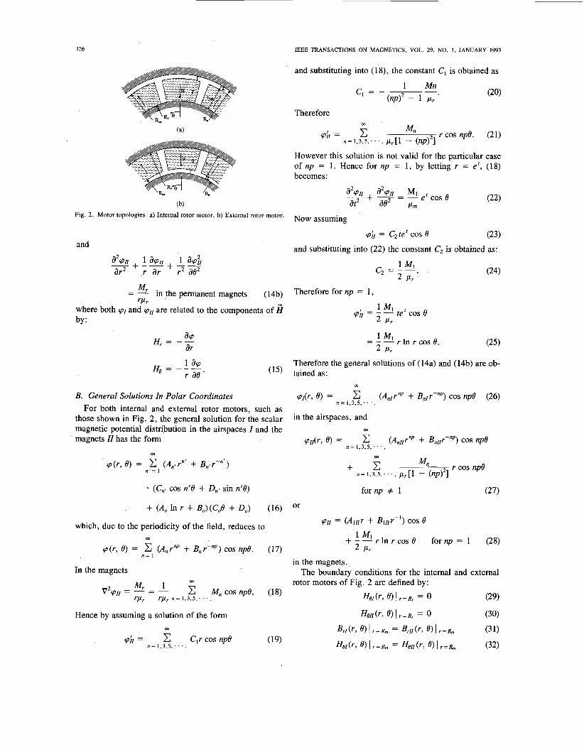
Now assuming Fig. 2. Motor topologies. a) Internal rotor motor. b) External rotor motor.
pi1 = C2 te' COS 8 (23) and substituting into (22) the constant C2 is obtained as: and
Mr - - - in the permanent magnets (14b) Therefore for nP = 1, rclr
1 Ml by : 2 pr where both pI and ~ 1 1 are related to the components of 5 = - - te' COS e
Therefore the general solutions of (14a) and (14b) are ob- (15) tained as:
m
B. General Solutions Zn Polar Coordinates pdr, 0) = (Anlrnp + BnIrPnP) cos np8 (26) For both internal and external rotor motors, such as
those shown in Fig. 2, the general solution for the scalar
magnets ZZ has the form
n = 1.3.5, . . . ,
in the airspaces, and magnetic potential distribution in the airspaces Z and the m
pII(r , 0) = (AnIIrnp + BnIIr-nP) cos np8 n = 1,3,5, . . . ,
m
p(r, 8) = (An, rn' + Bn, P ' ) n ' = 1
for np f 1 (27) (Cn8 cos nfB + Dnl sin n'8)
+ (A, In r + Bo) (COO + 0,) (16) Or
= (Alllr + BlI1r-') cos e + - - r In r cos 0
which, due to the periodicity of the field, reduces to 1 MI 2 pr
for np = 1 (28) m
p ( r , 8) = c (Anrnp + Bnr-nP) cos np8. (17) n = 1
in the magnets.
rotor motors of Fig. 2 are defined by: In the magnets The boundary conditions for the internal and external
(29)
m
c Mn cos np8. (18) &(r, e> I r=R, = 0 Mr 1 V2p, = - = - rp, rpr n = 1 , 3 , 5 ; . . ,
ZHU er al.: MAGNETIC FIELD DISTRIBUTION IN BRUSHLESS PERMANENT MAGNET DC MOTORS, PART I. , 127
where and
R, = R, - g R, = R, + g + h, for an external rotor motor. (33) g being the airgap length, and h, the radial thickness of the magnets.
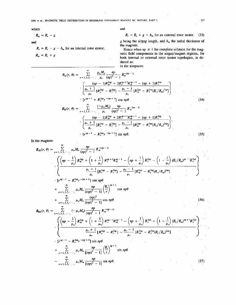
Hence when np # 1 the complete solution for the mag- netic field components in the airgaplmagnet regions, for both internal or external rotor motor topologies, is de- duced as: In the airspaces:
and
Rr = R, - g - h, for an internal rotor motor;
R,,, = R, + g
In the magnets:
128 IEEE TRANSACTIONS ON MAGNETICS, VOL. 29, NO. 1 , JANUARY 1993
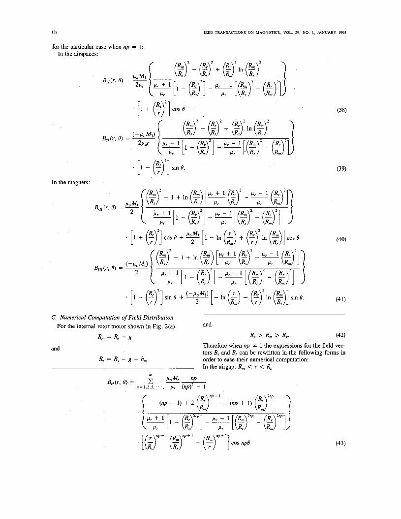
for the particular case when np = 1 In the airspaces:
[1 - e)2] sin e. In the magnets:
C. Numerical Computation of Field Distribution For the internal rotor motor shown in Fig. 2(a)
R, = R, - g
and
Rr = R, - g - h,
(39)
and
R, > R, > Rr. (42) Therefore when np # 1 the expressions for the field vec- tors Br and Be can be rewritten in the following forms in order to ease their numerical computation: In the airgap: R, < r < R,
ZHU et al.: MAGNETIC FIELD DISTRIBUTION IN BRUSHLESS PERMANENT MAGNET DC MOTORS, PART I. I29
In the magnets: R, < r < R,
(45)
However, for the external rotor motor shown in Fig. 2(b)
R, = R, + g and
R, e R, c R,. (47) and
Rr = R, + g + h, Therefore in order to facilitate numerkal computation for the case of np # 1 (34)-(37) are rewritten as: In the airgap: R, < r < R,
130 IEEE TRANSACTIONS ON MAGNETICS, VOL. 29, NO. 1, JANUARY 1993
In the magnets: R, < r < R, m
W
D. Magnetic Field Distribution At The Stator Surface ample, in the calculation of the induced emf waveform, In the preceeding sections general solutions have been
derived for the magnetic field distribution in both internal and external rotor motors. However often it is the radial component of the open-circuit flux density distribution at the stator surface which is of most significance, for ex-
the prediction of the cogging torque, and the radial force spectrum.
At the stator surface, Le., r = R,, the general expres- sion for the radial component of flux density in both in- ternal and external rotor motors becomes
W
ZHU el ai.: MAGNETIC FIELD DISTRIBUTION IN BRUSHLESS PERMANENT MAGNET DC MOTORS. PART I .
.4 -
131
- Analytical calarllbn 0 Finiteelementprodldbn 1 - I
.4
.2
€ .$ f 0 i
-.2
-.4 0 1 2 3
.2
I ' I
-
-*'i--B, , , , , , Flj 1 .o 1.5
-.4 0 .5
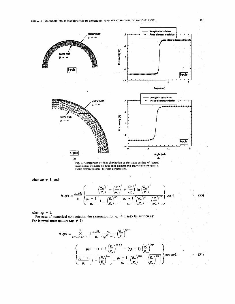
(a) (b) Fig. 3. Comparison of field distribution at the stator surface of intemal rotor motors predicted by both finite element and analytical techniques. a) Finite element meshes. b) Field distributions.
when np # 1 , and
cos e (53)
when np = 1 .
For intemal rotor motors (np # 1) For ease of numerical computation the expression for np # 1 may be written as:
132 IEEE TRANSACTIONS ON MAGNETICS, VOL. 29, NO. 1, JANUARY 1993
bwb IW r = Rs - g- bw*lndl i!rfl i n i!
-25 -15
5 1 0 .n -50
1 5 5 1 0 1 5
bw* Indl r = R s - g - h h bwb IW
( 4
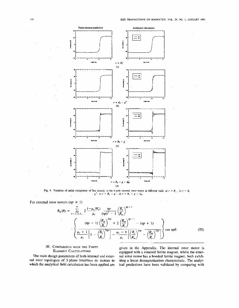
Fig. 4. Variation of radial component of flux density in the 4-pole intemal rotor motor at different radii a) r = R ; . b) r = R, - g'. c) r = R, - g-. d) r = R, - g - h:.
For external rotor motors (np # 1)
111. COMPARISON WITH THE FINITE ELEMENT CALCULATIONS
The main design parameters of both internal and exter- nal rotor topologies of 3-phase brushless dc motors to which the analytical field calculation has been applied are
given in the Appendix. The internal rotor motor is equipped with a sintered ferrite magnet, whilst the exter- nal rotor motor has a bonded ferrite magnet, both exhib- iting a linear demagnetization characteristic. The analyt- ical predictions have been validated by comparing with
ZHU el ai.: MAGNETIC FIELD DISTRIBUTION IN BRUSHLESS PERMANENT MAGNET DC MOTORS, PART I.
- Analytical calculation .30 8 8 - 8. 0 Finite element prediction
I33
8 8 I
I ‘Rum R,,
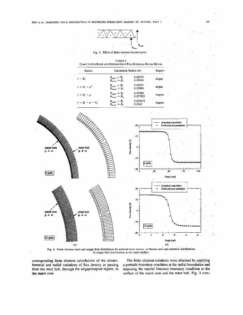
Fig. 5. Effect of finite element discretization.
TABLE I COMPUTATION RADII AND REGIONS FOR 4-POLE INTERNAL ROTOR MOTOR
Radius Calculation Radius (m) Region
airgap Rupper = Rl 0.02975 0.02950 R,,,,, = Rz
airgap Rupper = R3 0.02925 0.02900 RI,,,, = R4
magnet Rupper = R5 0.02900 0.027825 RI,,,, = Rs
Rupper = R7 0.025475 magnet 0.0243 RI,,,, = Rs
r = Rs-
r = R, - gf
r = R , - g -
r = R, - g - h,’
-.15
-.30 .25 .50 .75 1 .oo
Angle (rad)
- Analytical calculation .30
.15
€ $ s o
p=Ca x rotor hub
ii
-.15
-.30 1 .2 .3 .4 .5
Angle (rad)
(a) (b) Fig. 6. Finite element mesh and airgap field distribution for external rotor motors. a) Meshes and equi-potential distributions.
b) airgap field distributions at the stator surface.
corresponding finite element calculations of the circum- ferential and radial variations of flux density in passing from the rotor hub, through the airgaplmagnet region, to the stator core.
The finite element solutions were obtained by applying a periodic boundary condition at the radial boundaries and imposing the natural Neuman boundary condition at the surface of the stator core and the rotor hub. Fig. 3 com-
134 IEEE TRANSACTIONS ON MAGNETICS, VOL. 29, NO. 1 , JANUARY 1993
pares the open-circuit field distribution at the surface of stator bore for both the 2-pole and 4-pole internal rotor motors, whilst Fig. 4 compares the field distribution at different radii in the magnet/airgap region of the 4-pole motor. Since at each radius the finite element result is plotted froth the value of flux density in elements whose node alternate from an upper to a lower radius, Rupper and Rlower, as shown in Fig. 5 , the analytical predictions are given for the two corresponding radii, as shown in Table I. It will be seen that due to the effect of flux leakage the flux density is highest inside the magnets at the circum- ferential edges of the magnets, whilst outside the mag- nets, i.e., in the airgap, the flux density is lowest near the edges of the magnets.
It will also be noted that whilst the oscillations which exist in the field distributions plotted from the finite ele- ment results are due to the fluctuation of the radial coor- dinate of the centroid of alternate elements, the amplitude of the oscillation varying with the level of discretisation, the oscillations in the analytical predictions arise through the use of a finite number of terms in the Fourier series, harmonics with an amplitude smaller than 1 6 0 0 of the largest harmonic component being neglected. In general, however, the predictions from the analytical technique are in good agreement with the finite element calculations.
Fig. 6 compares analytical and finite element calcula- tions of the airgap flux density distribution at the surface of stator bore for both the 6- and 12-pole external rotor motors, again with the stator slot-openings neglected, and provides further evidence of the utility of the analytical technique.
IV. CONCLUSIONS A general 2-dimensional analytical method for predict-
ing the open-circuit field distribution in radial-field topol- ogies of permanent magnet motors has been established and validated against finite element calculations. The method can be refined to account for the effect of slotting on the field distribution by the introduction of a “two- dimensional” relative permeance function, as will be de- scribed in a companion paper [14] (part 111, this issue). Although the method has been applied to brushless dc mo- tors it is equally applicable to brushless permanent mag- net ac motors and brushed permanent magnet motors. The analytical model allows the induced emf waveform to be predicted for subsequent use in a dynamic simulation of a brushless dc drive so as to obtain the stator current waveform, thereby allowing the armature reaction field to be determined, as will be described in [13] (part 11, this issue). The resultant temporal and spatial dependent mag- netic field can then be utilised for predicting the acoustic noise and vibration from a motor, as will be discussed in Part IV, this issue.
ACKNOWLEDGMENTS The authors gratefully thank Philips GmbH, Aachen for
permission to publish this work.
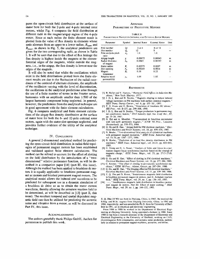
APPENDIX PARAMETERS OF PROTOTYPE MOTORS
TABLE I1 PARAMETERS OF PROTOTYPE INTERNAL AND EXTERNAL ROTOR MOTORS
Parameter Symbol Internal Rotor External Rotor Unit
Pole number 2P Slot number Q,
Airgap length g Radial thickness h,
R, Slot-opening bo Magnet B,
Relative recoil P r
Pole-adpole-pitch ap ratio
of magnet Stator radius
remanence
permeability
2 or4
1 .o
0.00075 0.0045
0.02975 0.00205 0.38
1 .os
12 6 or 12 - 9 1 .o
- -
0.00043 m 0 .OO 187 m
0.0207 m 0.0014 m 0.25 T
1.02 -
REFERENCES
B. Heller and V. Hamata, “Harmonic Field Effects in Induction Ma- chines,” New York: Elsevier, 1977. J. D. L. Ree and N. Boules, “Magnetic shaping to reduce induced voltage harmonics in PM machines with surface mounted magnets,” IEEE Trans. Energy Conver., vol. 6, pp. 155-161, 1991. P. D. Evans and D. Brown, “Simulation of brushless DC drives,” IEE Proc., vol. B-137, pp. 299-308, 1990. J. D. L. Ree and N. Boules, “Torque production in permanent mag- net synchronous motors,” IEEE Industry Appl. SOC. Con$ Rec., 87,
G. Eid and A. Mouillet, “Transistorized dc brushless micromotor with rare-earth permanent magnets,” ICEM ’84 Proc., Lausanne (Switzerland), pp. 570-573, 1984. Q. Gu and H. Gao, “Airgap field for PM electrical machines,” Elec- trical Machines and Power Systems, vol. 10, pp. 459-470, 1985. N. Boules, “Two-dimensional field analysis of cylindrical machines with permanent magnet excitation,” IEEE Trans. Industrial Appl., vol. IA-20, pp. 1267-1277, 1984. N. Boules, “Prediction of no-load flux density distribution in PM machines,” IEEE Trans. Industrial Appl., vol. IA-21, pp. 633-643, 1985. G. Xiong and S. A. Nasar, “Analysis of fields and forces in a per- manent magnet linear synchronous machine based on the concept of magnetic charge,” IEEE Trans. Magn., vol. 25, pp. 2713-2719, 1989. Q . Gu and H. Gao, “Effect of slotting in PM electrical machines,” Electrical Machines and Power Systems, vol. 10, pp. 273-284, 1985. C. Kramer, “The effect of slotting in permanentic synchronous ma- chines,” ICEM ’80 Proc., Athens, Greece, pp. 287-294, 1980. Q . Gu, and H. Gao, “The fringing effect in PM electrical machines,” Electrical Machines and Power Systems, vol. 1 1 , pp. 159-169, 1986. Z. Q . Zhu and D. Howe, “Instantaneous magnetic field distribution in brushless permanent magnet dc motors, part 11: Armature reaction field,” IEEE Trans. Magn., vol. 29, no. 1 , pp. 136-143, 1993. __ , “Instahaneous magnetic field distribution in brushless perma- nent magnet dc motors, Part 111: Effect of stator slotting,” IEEE Trans. Magn., vol. 29, no. 1, pp. 144-152, 1993.
pp. 15-20, 1987.
2. Q. Zhu (M’90) was born in Zhejiang, China, in 1962. He received the B.Eng. and M.Sc. degrees from Zhejiang University, China, in 1982 and 1984, respectively, and was awarded the Ph.D. from the University of Shef- field in 1991, all in electrical and electronic engineering.
From 1984 to 1988 he worked in the Department of Electrical Engi- neering at Zhejiang University, being appointed a lecturer in 1986. Since 1988 he has been a research associate in the Department of Electronic and Electrical Engineering at the University of Sheffield, working on CAD, electromagnetic field computation, and acoustic noise prediction, particu- larly in relation to permanent magnet machines, actuators, and drives.
ZHU et al.: MAGNETIC FIELD DISTRIBUTION IN BRUSHLESS PERMANENT MAGNET DC MOTORS, PART I. I35
David Howe was bom in Sheffield, England in 1943. He received the B. Tech, and M.Sc. degrees in Electrical Power Engineering from the Uni- versity of Bradford and the Ph.D. from Southampton University.
He has held academic posts at Brunel and Southampton Universities, and spent a period in industry with NE1 Parsons Ltd. working on electromag- netic problems ip turbo-generators. He is currently Professor of Electrical Engineering at the University of Sheffield where he heads the Electrical Machines and Drives Research Group. His research activities span all fac- ets of controlled electrical drive systems, with particular emphasis on per- manent magnet excited machines.
Professor Howe has published extensively.
Ekkehard Bolte was bom in Germany in 1952. He received the Dr.-Ing. degree in Electrical Engineering from the University of Hannover and Dortmund in 1979 for research into asynchronous motors with solid iron secondary.
He currently heads the Electromechanics and Power Electronics Depart- ment at Philips Research Laboratories, Aachen, Germany. His professional interests embrace all aspects of electromechanical power conversion and electronic supplies.
Bernd Ackermann was born in Germany in 1957, and received the Dipl.Phys. degree from the Technical University of Darmstat in 1982. He received the Dr.rer.nat. degree from the University of Duisburg in 1985.
From 1983 to 1985 he worked at the solid state physics institute at Kem- forschungsanlage Julich, Germany. Since then he has been working as a scientist at the Electromechanics and Power Electronics Department at Philips Research Laboratories, Aachen, Germany. At present he is working on the design of brushless DC motors for consumer products.