Embed Size (px)
Citation preview
Toward Impact-resilient Quadrotor Design, Collision Characterization andRecovery Control to Sustain Flight after Collisions
Zhichao Liu and Konstantinos Karydis
Abstract— Collision detection and recovery for aerial robotsremain a challenge because of the limited space for sensorsand local stability of the flight controller. We introduce anovel collision-resilient quadrotor that features a compliantarm design to enable free flight while allowing for one passivedegree of freedom to absorb shocks. We further propose anovel collision detection and characterization method basedon Hall sensors, as well as a new recovery control method togenerate and track a smooth trajectory after a collision occurs.Experimental results demonstrate that the robot can detect andrecover from high-speed collisions with various obstacles suchas walls and poles. Moreover, it can survive collisions that arehard to detect with existing methods based on IMU data andcontact models, for example, when colliding with unstructuredsurfaces, or being hit by a moving obstacle while hovering.
I. INTRODUCTION
Unmanned aerial vehicles (UAVs) proliferate across ap-plications [1]. Among UAVs, the quadrotor has become thestandard of practice [2]. Advances in control of quadro-tors [3, 4], allow them to perform tasks such as acrobatics [5],grasping [6], perching [7], carrying suspended payloads [8],and flying through narrow gaps [9, 10]. An integral part ofUAV operation is collision avoidance. However, despite ad-vances in integration of perception and planning for collisionavoidance (e.g., [11–13]), quadrotors still remain vulnerableto collisions that may occur because of unreliable sensors orunpredictable disturbances [14]. The challenge becomes pro-nounced as quadrotors are tasked to operate in increasinglycomplex, cluttered and partially-known environments.
The thesis adopted is this work is that instead of com-pletely avoiding collisions it may be beneficial to cope withthem [15–18]. In fact, sustaining flight after collision—aproperty that most existing works cannot guarantee [19]—may be crucial to deploy quadrotors in complex and clutteredenvironments. The capability to withstand and recover fromcollisions has been shown to benefit aerial robot navigationin partially-known environments [20, 21].
We introduce a novel actively resilient quadrotor (ARQ),which incorporates passive springs within its frame to absorbshocks and survive collisions. The quadrotor is equipped withHall sensors to accurately and rapidly detect the location(in the robot’s frame) and intensity of a collision. To takeadvantage of the injected compliance and resulting resilienceto collisions, we further develop a recovery controller that
The authors are with the Dept. of Electrical and Computer Engineering,University of California, Riverside. Email: zliu157, [email protected]. Wegratefully acknowledge the support of NSF # IIS-1910087, ARL # W911NF-18-1-0266, and ONR # N00014-19-1-2264. Any opinions, findings, andconclusions or recommendations expressed in this material are those of theauthors and do not necessarily reflect the views of the funding agencies.
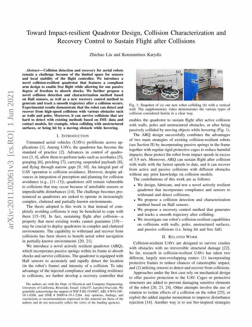
Fig. 1: Snapshot of (a) our new robot colliding (b) with a verticalwall. The supplementary video demonstrates the various types ofcollision considered herein in a clear way.
enables the quadrotor to sustain flight after active collisionwith walls, poles and unstructured obstacles, or after beingpassively collided by moving objects while hovering (Fig. 1).
The ARQ design successfully combines the advantagesof two main strategies of existing collision-resilient robots(see Section II) by incorporating passive springs in the frametogether with regular rigid protective cages to reduce harmfulimpacts; these protect the robot from impact speeds in excessof 5.9 m/s. Moreover, ARQ can sustain flight after collisionwith walls with the fastest speeds to date, and it can recoverfrom active and passive collisions with different obstacleswithout any prior knowledge on collision models.
The contributions of this work are as follows:• We design, fabricate, and test a novel actively resilient
quadrotor that incorporates compliance and sensors towithstand and detect collisions.
• We propose a collision detection and characterizationmethod based on Hall sensors.
• We propose a recovery control method that generatesand tracks a smooth trajectory after colliding.
• We investigate our robot’s collision-resilient capabilitieson collisions with walls, poles, unstructured surfaces,and passive collisions (i.e. being hit and free fall).
II. RELATED WORK
Collision-resilient UAVs are designed to survive crasheswith obstacles with no irreversible structural damage [22].So far, research in collision-resilient UAVs has taken twodifferent, largely non-overlapping routes: (1) incorporatingprotective frames to reduce chances of catastrophic impact,and (2) utilizing sensors to detect and recover from collisions.
Approaches under the first case rely on mechanical designto offer passive protection to the UAV. Cages or protectivestructures are added to prevent damaging sensitive elementsof the robot [20, 23, 24]. Other attempts involve the use ofrotation to isolate effects of a collision on the robot [25], orexploit the added angular momentum to improve disturbancerejection [14]. Another way is to use bio-inspired strategies
arX
iv:2
011.
0206
1v3
[cs
.RO
] 1
Jun
202
1

and soft materials to survive crashes [22, 26, 27]. However,careful mechanical design alone cannot help detect andcharacterize collisions, which is essential to sustain flight.
Works on sensor-based collision detection and character-ization have mainly focused on using data from the inertialmeasurement unit (IMU). External wrench estimation [19],multiplicative extended Kalman filter (MEKF) [28] and fuzzylogic process (FLP) [29] have been found feasible to detectand characterize collisions with the onboard IMU, to assistrecovery control. However, those methods rely on priorknowledge of collision dynamics or require data for trainingcollision models, thereby limiting applicability for collision-resilient control. Further, IMUs are usually unable to distin-guish collisions during aggressive flight and to detect staticcontacts, resulting in low accuracy in collision detection [30].Position error between IMU data and ground truth frommotion capture [20], and accelerometer data alone [21] canidentify collisions; however, the methods cannot localizecollisions, which is key to sustain flight.
The use of Hall sensors (as in here) has been used in thepast to provide more accurate collision detection [30], albeitfor a very different airframe with two rotors aligned verti-cally. However, and critically different from our work, [30]does not focus on collision recovery control. In addition,when compared to other works on design of resilient UAVswith collision detection, our work uniquely integrates physi-cal compliance to reduce the detrimental impacts of collision.
III. HARDWARE AND SOFTWARE DESIGN OF ARQ
The quadrotor is built based on off-the-shelf componentsand custom 3D-printed parts. To embrace collision andenable recovery, each arm of ARQ integrates a shock ab-sorber and Hall sensor. The platform features custom nylonprotective cages, a Pixhawk 4 Mini flight controller with theopen-source PX4 autopilot firmware, an Odroid XU4 withthe ROS environment as the companion computer, and anArduino Nano for analog to digital conversion (Fig. 2).
Fig. 2: ARQ main components. Each arm is equipped with a shockabsorber and Hall sensor to withstand and detect collisions.
A. Electro-mechanical Hardware Prototyping
Key components of ARQ include its compliant arm designand the integration of Hall sensors to estimate deformations.
1) Compliant Arm Design: Unlike existing resilient flyingrobots whose physical configurations are drastically changedafter collision [22, 27], the configuration of ARQ remains thesame before and after a collision. This property makes ARQ
an appropriate platform to conduct complex tasks that requiremodel-based control. To this end, our design uniquely retainsrigidity when in free flight while allowing for one passivedegree of freedom in the direction along each arm to absorbharmful impacts from collision.
Fig. 3: The computer-aided design (CAD) for an ARQ’s novel arm.
The computer-aided design (CAD) assembly and maincomponents of ARQ’s novel arm are shown in Fig. 3. Theprismatic joint is built based on a solid brass 2-inch surfacebolt. The bolt is covered by heat-shrinkable tubes to reducethe free space within the joint. The aluminum shock absorberis taken from 1/18 radio-control cars. An A1302 ratiometriclinear Hall sensor is fixed on the prismatic joint to measurethe magnetic intensity. The adapters connecting the prismaticjoint and shock absorber are 3D-printed (Markforged MarkII, onyx material with carbon fiber add-in). The stiffness ofthe spring within the shock absorber is adjusted so that thelength of the arm remains unchanged during free flight.
2) Hall Sensor: The ability to detect and characterizecollisions is critical to stabilize quadrotors and sustain flight.Existing collision-detection methods with IMUs require de-tailed modeling of the environment and obstacles [29], lim-iting application in unknown environments. In this work, weuse Hall sensors for collision detection as in [30].
Hall sensors are commonly used to measure the magnitudeof a magnetic field. The sensor’s output voltage is directlyproportional to the magnetic field strength through it. In ourprototype, A1302 ratiometric linear Hall sensors are fixedon the prismatic joints, coming in contact with the magnetwhen the length of a shock absorber reduces to its minimum.Despite the relatively short distance, the rotating motorswere observed to have almost no effect on the Hall sensors’readings. Experimental testing showed that the output of thesensor was changed by less than 0.5% for all motor speeds.Hall sensors and embedded magnets do not affect the IMUin the flight control unit as well, which makes the detectionmethod promising to be adopted outdoors. Experimentaltesting showed that the yaw estimation of the IMU was notaffected by Hall sensors or the embedded magnets.
Admittedly, using only one sensor for each arm does notallow to measure a collision precisely, unless the direction ofcollision is exactly aligned with the arm. However, it allowsto detect whether the quadrotor is in contact with an obstacleor not, and give an approximation of the collision intensity.By utilizing four Hall sensors, the quadrotor can approximatewhere the collision occurs in the body frame. We elaborateon the collision detection and characterization in Section IV.
B. Modeling and Control1) Notation: We use world, W , and body, B, frames
with orthonormal bases xW , yW , zW and xB , yB , zB,

respectively. The body frame is fixed to the quadrotor withthe origin located at the center of mass. The position,velocity and acceleration of the quadrotor’s center of massare denoted by x ∈ R3, v ∈ R3 and a ∈ R3, respectively.Vector subscripts denote the frame the vector is expressedat, for example, xB represents the position in the bodyframe. Vectors without subscript are expressed in the worldframe. RBW denotes a rotation matrix from the body frameto the world frame. For clarity, in the following we use R torepresent RBW ; subscript d (e.g. xd) denotes desired values.
2) Model: The quadrotor equations of motion are [20]
x = vmv = −mge3 + fRe3
R = RΩ
JΩ + Ω× JΩ = M
where m is the mass and g is the gravitational accelerationconstant. Unit vector e3 represents the direction of gravity inthe world frame. Ω denotes the angular velocity in the bodyframe, and Ω is the skew-symmetric matrix representationof Ω. f and M =
[M1 M2 M3
]Tare the force and torque
control inputs. These are determined byf
M1
M2
M3
=
1 1 1 1
0 l 0 −l−l 0 l 0
cf −cf cf −cf
f1
f2
f3
f4
, (1)
where l is the arm length and cf is the thrust coefficient.When a collision happens, the arm length shortens, thus
altering the required thrust as per (1). However, by takingadvantage of Hall sensors, ARQ waits until an elastic col-lision has been terminated and the nominal arm length l isrecovered. This way, model (1) can be used before and aftercollision.1
3) Controller: We deploy a geometric tracking controllerfor quadrotors [3]. Control inputs f , M are chosen as
f =(−kxex − kvev +mge3 +mxd) · Re3 (2)M =−kReR − kΩeΩ + Ω× JΩ
−J(ΩRTRdΩd − RTRdΩd) (3)
Tracking errors are given by ex = x − xd; ev = v −vd; eR = 1
2 (RTd R − RTRd)∨; and eΩ = Ω − RTRdΩd,where the vee map ∨ is the inverse of a skew-symmetricmapping. Readers are referred to [3] for detailed derivationsand stability analysis of the controller.
C. Software Architecture
The software is developed in C++ using the ROS frame-work (Fig. 4). The flight controller Pixhawk 4 Mini, com-panion computer Odroid XU4 and the Arduino Nano are allmounted on the quadrotor (Fig. 2). The Odroid runs Ubuntu16.04 LTS and communicates with a 12-camera VICON mo-tion capture system server over Wi-Fi for odometry feedback.
1During waiting to recover the original arm length (< 1 sec), the flightcontroller computes rotor thrusts according to the original arm length l.
Fig. 4: Overview for the software architecture of ARQ.
Three nodes are running within the Odroid. The first one isthe MAVROS node to communicate with the PX4 firmwarein Pixhawk via MavLink. The second node is the trajectorygeneration node, which will be elaborated in Section V.The trajectory generation node outputs the desired position,velocity, acceleration, yaw, and yaw rate to the geometriccontroller node. Finally, the controller node calculates andsends the desired thrust and attitude to the flight controller.
The Pixhawk 4 Mini runs in offboard mode. The inbuiltMAVROS function setpoint raw/attitude is calledat 50Hz to set motors commands according to the given thrustand attitude data. The Pixhawk runs an internal extendedKalman filter (EKF) to fuse IMU data and estimate thequadrotor’s pose and orientation.
One Arduino Nano connects four Hall sensors and con-verts the analog signals to digital ones. The Arduino sendsdigital readings to the Odroid via UART at 200Hz forcollision detection and characterization.
IV. COLLISION DETECTION AND CHARACTERIZATION
The Hall sensor used herein outputs a voltage proportionalto the magnetic field strength through it. We fix a magnet atone side of the shock absorber and place the Hall sensor atthe other end (see Fig. 3). When a collision happens, thecontact force will shorten the spring in the absorber, therebyreducing the distance between a Hall sensor with a magnet,thus increasing the output voltage recorded in the Arduino.
Fig. 5: Characterization of a collision vector CB .
Figure 5 illustrates how ARQ estimates the location andintensity of a collision CB in the body frame. There are fourvectors di that represent the collision detected by the Hallsensors along the arms. Let di ∈ [0, 1], i = 1, 2, 3, 4 denotevalues from the analog to digital conversions, where di = 0means no contact force is detected and di = 1 indicates thatthe minimum length of the shock absorber has been reached.

To estimate the intensity and location of the collisionCB , we need to calculate its magnitude CB and orientationΨB ∈ (−π, π] (positive orientation corresponds to counter-clock direction). First, all vectors di are projected onto thebasis xB and yB with di,x, di,y . For example, the projectionsof d1 can be written as d1,x = d1 cos θ2 ; d1,y = −d1 sin θ
2 ,where θ = ∠(d1,d2) represents the angle between thevectors d1 and d2. After adding up all projections, we areable to characterize the collision via
dx =
4∑i=1
di,x ,
dy =
4∑i=1
di,y ,
CB =√d2x + d2
y ,
ΨB = atan2(dy, dx) .
An effective collision detection requires both accuracyand an appropriate time of detection td to initiate recoverycontrol. Unlike existing methods that often rely on certainthresholds to decide on collision occurrence and detectiontime, detection herein is based on an algorithm to measurethe maximum collision intensity and time td.
The algorithm initiates with zero for the maximum colli-sion intensity CB and false for the collision detection flag.While there is no collision detected, the loop reads datafrom the Hall sensors at current time j and computes CB,jand ΨB,j as discussed previously. We empirically choose athreshold of 0.1 to reduce effects from sensor noise. Whena collision intensity greater than the threshold is detected,the loop compares the current collision magnitude with themaximum one and saves the value if the current collisionmagnitude is greater. After a maximum collision magnitudeis found, the algorithm starts counting for the loop and setsthe collision flag true after N loops afterward, where N isselected so that td is close to the time when the lengths of thearms recover to satisfy the nominal length dynamic model.
V. RECOVERY CONTROL DESIGN
Existing works in recovery control use different stages totrack, resulting in discontinuities in the overall trajectory [29,31]. On the contrary, the proposed recovery controller doesnot have multiple stages, leading to a smooth desired trajec-tory to track. This single-stage control design can improvethe recovery robustness and applies to collisions with avariety of objects such as walls and poles.
We follow a minimum-snap trajectory generation [32,33]. Minimum-snap polynomial splines can be effective forquadrotor trajectory planning since the motor commands andattitude accelerations of the vehicle are proportional to thesnap of the path. Minimizing the snap of a trajectory canmaintain the quality of onboard sensor measurements whileavoiding abrupt or excessive control inputs [33].
After a collision occurs, we seek to make the quadrotorreturn to a position xd that is in the opposite direction of thecollision at a distance proportional to the collision intensity.
We constrain the recovery position xd to be at the sameheight as the collision position. Thus, we can find the desiredposition in the body frame xd,B as
xd,B = Rot(z,ΨB) [−CB 0 0]T
where Rot(z,ΨB) is the rotation matrix along the z-axis byangle ΨB . Then, xd in the world frame is xd = RT xd,B .
For the flat output variables x, y, z and yaw angle, wefix the yaw angle and only consider x =
[x y z
]T. A
single trajectory segment between two points is composedof independent polynomials P (t) for x. A cost functionpenalizes the squares of fourth-order derivatives of P (t) as
J =
∫ T
0
c4P(4)(t)2dt = pTQp (4)
Vector p contains the N = 10 coefficients of a singlepolynomial. Only the fourth-order derivative of P (t) isinvolved in (4) to minimize snap. We refer readers to [33]for details on the construction of the Hessian matrix Q.
The optimization is formulated as
minimizep
J = pTQp
subject to Ap = b
Equality Ap = b imposes endpoint constraints x(0) =x0, x(0) = v0, x(T ) = xd, where x0, v0 are the positionand velocity of the quadrotor when collision happens andT is estimated based on the maximum acceleration andvelocity [33]. The velocity and acceleration at t = T are setto zero. Note we do not command the acceleration at t = 0since feedback from motion capture has no acceleration data.
VI. EXPERIMENTS AND RESULTS
The ARQ measures 380 mm from propeller tip to tipand 590 mm from protection cage tip to tip. We use a3500 mAh 3-cell LiPo battery to power the quadrotor. Therobot weighs 1.419 kg with the battery and has a maximumthrust-to-weight ratio of 4.58. The average energy efficiencyis 2.2 g/W. During experiments, the actual thrust-to-weightratio is limited to 2 by reducing the maximum pulse widthmodulation (PWM) values. A safety tether connects the robotto prevent damages in case of losing control. The safetytether is lightweight, and we did not observe any impacton the flight. We manually command the robot to take offin stabilized mode then switch to the offboard mode to letit hover before tests. When tests are done, we switch backto stabilized mode again to manually land. The collision-resilient performance of ARQ is evaluated through fiveexperiments: passive collision, wall collision, pole collision,colliding with unstructured surfaces, and free fall.
A. Passive Collision
As UAVs are tasked to explore more dynamic environ-ments, the robot can be hit by an obstacle while hovering.We call this type of collision as a passive collision. ARQ canhandle passive collisions thanks to its equipped Hall sensorsthat allow for rapid collision detection while hovering. Inour tests, the ARQ is being hit along the direction of an
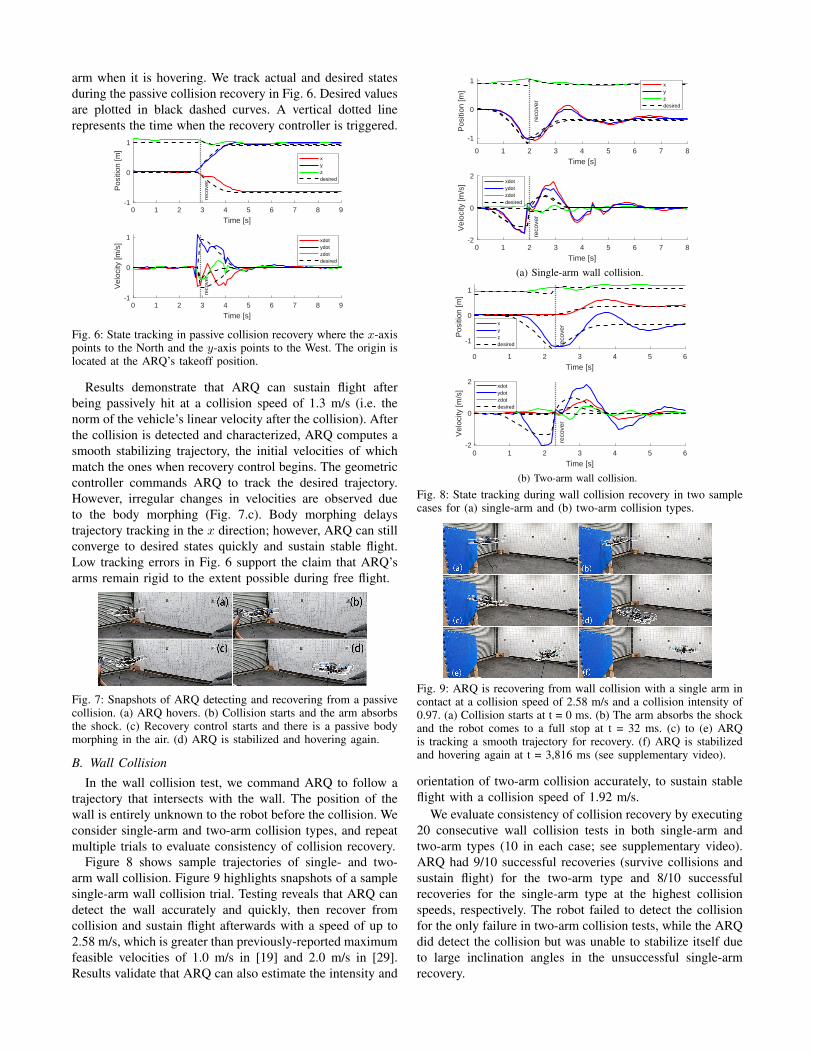
arm when it is hovering. We track actual and desired statesduring the passive collision recovery in Fig. 6. Desired valuesare plotted in black dashed curves. A vertical dotted linerepresents the time when the recovery controller is triggered.
0 1 2 3 4 5 6 7 8 9
Time [s]
-1
0
1
Pos
ition
[m]
reco
ver
xyzdesired
0 1 2 3 4 5 6 7 8 9
Time [s]
-1
0
1
Vel
ocity
[m/s
]
reco
ver
xdotydotzdotdesired
Fig. 6: State tracking in passive collision recovery where the x-axispoints to the North and the y-axis points to the West. The origin islocated at the ARQ’s takeoff position.
Results demonstrate that ARQ can sustain flight afterbeing passively hit at a collision speed of 1.3 m/s (i.e. thenorm of the vehicle’s linear velocity after the collision). Afterthe collision is detected and characterized, ARQ computes asmooth stabilizing trajectory, the initial velocities of whichmatch the ones when recovery control begins. The geometriccontroller commands ARQ to track the desired trajectory.However, irregular changes in velocities are observed dueto the body morphing (Fig. 7.c). Body morphing delaystrajectory tracking in the x direction; however, ARQ can stillconverge to desired states quickly and sustain stable flight.Low tracking errors in Fig. 6 support the claim that ARQ’sarms remain rigid to the extent possible during free flight.
Fig. 7: Snapshots of ARQ detecting and recovering from a passivecollision. (a) ARQ hovers. (b) Collision starts and the arm absorbsthe shock. (c) Recovery control starts and there is a passive bodymorphing in the air. (d) ARQ is stabilized and hovering again.
B. Wall Collision
In the wall collision test, we command ARQ to follow atrajectory that intersects with the wall. The position of thewall is entirely unknown to the robot before the collision. Weconsider single-arm and two-arm collision types, and repeatmultiple trials to evaluate consistency of collision recovery.
Figure 8 shows sample trajectories of single- and two-arm wall collision. Figure 9 highlights snapshots of a samplesingle-arm wall collision trial. Testing reveals that ARQ candetect the wall accurately and quickly, then recover fromcollision and sustain flight afterwards with a speed of up to2.58 m/s, which is greater than previously-reported maximumfeasible velocities of 1.0 m/s in [19] and 2.0 m/s in [29].Results validate that ARQ can also estimate the intensity and
0 1 2 3 4 5 6 7 8
Time [s]
-1
0
1
Pos
ition
[m]
reco
ver
xyzdesired
0 1 2 3 4 5 6 7 8
Time [s]
-2
0
2
Vel
ocity
[m/s
]
reco
ver
xdotydotzdotdesired
(a) Single-arm wall collision.
0 1 2 3 4 5 6
Time [s]
-1
0
1
Pos
ition
[m]
reco
verx
yzdesired
0 1 2 3 4 5 6
Time [s]
-2
0
2
Vel
ocity
[m/s
]
reco
ver
xdotydotzdotdesired
(b) Two-arm wall collision.
Fig. 8: State tracking during wall collision recovery in two samplecases for (a) single-arm and (b) two-arm collision types.
Fig. 9: ARQ is recovering from wall collision with a single arm incontact at a collision speed of 2.58 m/s and a collision intensity of0.97. (a) Collision starts at t = 0 ms. (b) The arm absorbs the shockand the robot comes to a full stop at t = 32 ms. (c) to (e) ARQis tracking a smooth trajectory for recovery. (f) ARQ is stabilizedand hovering again at t = 3,816 ms (see supplementary video).
orientation of two-arm collision accurately, to sustain stableflight with a collision speed of 1.92 m/s.
We evaluate consistency of collision recovery by executing20 consecutive wall collision tests in both single-arm andtwo-arm types (10 in each case; see supplementary video).ARQ had 9/10 successful recoveries (survive collisions andsustain flight) for the two-arm type and 8/10 successfulrecoveries for the single-arm type at the highest collisionspeeds, respectively. The robot failed to detect the collisionfor the only failure in two-arm collision tests, while the ARQdid detect the collision but was unable to stabilize itself dueto large inclination angles in the unsuccessful single-armrecovery.

To demonstrate the individual contribution of complianceand the recovery control components, two additional walltests are conducted with a collision speed of 2.3 m/s. Inthe first test, the arms remain compliant but the recoverycontroller is disabled. In the second test, we fix the armsin place using custom jigs (these add 25 g of weight to therobot) while the recovery controller is disabled. Experimentaltrials (see supplementary video) show that compliance alonecan reduce collision impact (as expected), but cannot helpsustain fight; the robot falls to the ground after getting stuckto the wall for several seconds because of lack of recoverycontrol. In the second test, we observe a worse impact whichmakes the robot fall to the ground immediately. The twotests support our hypothesis that compliance can reducedetrimental impacts from collisions while recovery controlis essential to sustain fight afterwards.
C. Pole Collision
The robot can also recover from collisions withcylindrical/pole-like objects. In our tests, we use a cylinderof 300 mm diameter (Fig. 10.a) and command ARQ to hitthe object with a collision speed of 2.04 m/s.
Testing demonstrates that ARQ can accurately detect polecollisions without any additional changes in hardware andsoftware. The recovery process is very similar to the onewith vertical walls, except the collision intensity (0.20) ismuch smaller, due to the shape of the obstacle. However,the recovery controller still manages to stabilize the robotwith a hovering position close to the obstacle. The recoverydoes not have multiple discontinuous phases as in [31], andthe robot tracks a smooth trajectory throughout the recovery.
Fig. 10: ARQ can detect and recover from collisions with (a) a poleand (b) unstructured surface (see supplementary video).
D. Unstructured Surface Collision
Unlike IMU-based methods, ARQ does not require priorknowledge of collision models to handle collisions. Wedesign a collision test on an unstructured surface (Fig. 10.b)to demonstrate this property. It is very challenging to derive acontact model for such irregular surfaces, while the collisionposition is uncertain that makes it even harder to detect thecollision based on contact modeling.
We command ARQ to hit the unstructured surface with acollision speed of 1.95 m/s. Testing demonstrates that ARQcan quickly and accurately detect collisions with unstructuredsurfaces thanks to the Hall sensors along the arms. Followinga smooth desired trajectory after the collision, ARQ canstabilize itself and return to the hovering state. ARQ’s abilityto survive a collision with the unstructured surface is key forUAVs to be deployed in unknown environments.
E. Free FallTo better demonstrate the benefit of adding compliance, we
conduct a free fall test with ARQ (Fig. 11). ARQ is found tosurvive free falls from 1.8 m high and reaching a maximumvelocity of 5.9 m/s without any damage to the robot.2
Fig. 11: Drop test from 1.8m reaching a velocity of 5.9m/s.
VII. CONCLUSIONS
Contributions and Key Findings: The paper introducesa novel actively resilient quadrotor (ARQ) that can detectcollisions quickly and accurately while staying compliant tomitigate damaging collision impacts. The arm is shown tosuccessfully meet the challenge of retaining rigidity in theabsence of collision (i.e. during free flight) while allowingone passive degree of freedom in the direction along the arm.Four Hall sensors with shock absorbers make ARQ able todetect collision without IMU data and prior modeling infor-mation for obstacles. With the extra resilience to collisions,we propose a new collision detection and characterizationmethod, followed by a novel recovery control method togenerate and track a smooth trajectory for collision recovery.
Experimental results demonstrate that ARQ can detectand recover from several types of collision at high speeds.We further study passive collisions (i.e. the robot being hitby a moving obstacle), which may occur unexpectedly atdynamic environments. In all cases, the robot can recoverfrom collisions and sustain flight afterwards. ARQ had 80%success rate for single-arm wall collisions at a speed of2.58 m/s and 90% for two-arm wall collisions at 1.92 m/s.
Directions for Future Work: Despite the robot’scollision-resilient performance demonstrated herein acrossobjects that are predominantly encountered in applica-tions [29], the current design is unable to detect and react toperpendicular obstacles (e.g., collisions from the top or thebottom) or purely rotational impacts. Future directions ofresearch include 1) improved design of the protective cageto handle perpendicular to the frame and purely rotationalcollisions and to adapt to collisions with large inclination an-gles, 2) a comprehensive study to identify feasible maximumvelocities for collision with a larger set of obstacles, and 3)deployment and testing in outdoor natural environments.
2The battery is removed in this test as the physical connection in thisfirst prototype is loose, but future iterations of the robot will resolve this;however, removing the battery does not alter the nature of the free fall test.The robot weighs 1.12 kg without the battery.

REFERENCES
[1] S. Gupte, P. I. T. Mohandas, and J. M. Conrad, “A survey of quadrotorunmanned aerial vehicles,” in Proceedings of IEEE Southeastcon,2012, pp. 1–6.
[2] K. Karydis and V. Kumar, “Energetics in robotic flight at small scales,”Interface Focus, vol. 7, 2017.
[3] T. Lee, M. Leok, and N. H. McClamroch, “Geometric tracking controlof a quadrotor uav on se (3),” in IEEE Conference on Decision andControl (CDC), 2010, pp. 5420–5425.
[4] D. Mellinger, N. Michael, and V. Kumar, “Trajectory generationand control for precise aggressive maneuvers with quadrotors,” TheInternational Journal of Robotics Research, vol. 31, no. 5, pp. 664–674, 2012.
[5] D. Brescianini, M. Hehn, and R. D’Andrea, “Quadrocopter pole ac-robatics,” in IEEE/RSJ International Conference on Intelligent Robotsand Systems (IROS), 2013, pp. 3472–3479.
[6] J. Thomas, G. Loianno, J. Polin, K. Sreenath, and V. Kumar, “Towardautonomous avian-inspired grasping for micro aerial vehicles,” IOPBioinspiration & Biomimetics, vol. 9, no. 2, p. 025010, 2014.
[7] J. Thomas, G. Loianno, M. Pope, E. W. Hawkes, M. A. Estrada,H. Jiang, M. R. Cutkosky, and V. Kumar, “Planning and control ofaggressive maneuvers for perching on inclined and vertical surfaces,”in ASME International Design Engineering Technical Conferences andComputers and Information in Engineering Conference, 2015.
[8] S. Tang, V. Wuest, and V. Kumar, “Aggressive flight with suspendedpayloads using vision-based control,” IEEE Robotics and AutomationLetters, vol. 3, no. 2, pp. 1152–1159, 2018.
[9] D. Falanga, K. Kleber, S. Mintchev, D. Floreano, and D. Scaramuzza,“The foldable drone: A morphing quadrotor that can squeeze and fly,”IEEE Robotics and Automation Letters, vol. 4, no. 2, pp. 209–216,2018.
[10] N. Bucki and M. W. Mueller, “Design and control of a passivelymorphing quadcopter,” in IEEE International Conference on Roboticsand Automation (ICRA), 2019, pp. 9116–9122.
[11] K. Mohta, M. Watterson, Y. Mulgaonkar, S. Liu, C. Qu, A. Makineni,K. Saulnier, K. Sun, A. Zhu, J. Delmerico, et al., “Fast, autonomousflight in gps-denied and cluttered environments,” Journal of FieldRobotics, vol. 35, no. 1, pp. 101–120, 2018.
[12] G. Aoude, B. Luders, J. Joseph, N. Roy, and J. P. How, “Probabilisti-cally safe motion planning to avoid dynamic obstacles with uncertainmotion patterns,” Auton. Robots, vol. 35, no. 1, pp. 51–76, 2013.
[13] D. Falanga, K. Kleber, and D. Scaramuzza, “Dynamic obstacle avoid-ance for quadrotors with event cameras,” Science Robotics, vol. 5,no. 40, 2020.
[14] N. Bucki and M. W. Mueller, “Improved quadcopter disturbancerejection using added angular momentum,” in IEEE/RSJ InternationalConference on Intelligent Robots and Systems (IROS), Oct 2018, pp.4164–4170.
[15] A. De Luca and R. Mattone, “Sensorless robot collision detectionand hybrid force/motion control,” in IEEE international conferenceon robotics and automation (ICRA), 2005, pp. 999–1004.
[16] K. Karydis, D. Zarrouk, I. Poulakakis, R. S. Fearing, and H. G. Tanner,“Planning with the star (s),” in IEEE/RSJ International Conference onIntelligent Robots and Systems (IROS), 2014, pp. 3033–3038.
[17] T. Erez and E. Todorov, “Trajectory optimization for domains withcontacts using inverse dynamics,” in IEEE/RSJ International Confer-ence on Intelligent Robots and Systems (IROS), 2012, pp. 4914–4919.
[18] M. Posa, C. Cantu, and R. Tedrake, “A direct method for trajectory op-timization of rigid bodies through contact,” The International Journalof Robotics Research, vol. 33, no. 1, pp. 69–81, 2014.
[19] T. Tomic, C. Ott, and S. Haddadin, “External wrench estimation,collision detection, and reflex reaction for flying robots,” IEEE Trans-actions on Robotics, vol. 33, no. 6, pp. 1467–1482, 2017.
[20] Y. Mulgaonkar, A. Makineni, L. Guerrero-Bonilla, and V. Kumar, “Ro-bust aerial robot swarms without collision avoidance,” IEEE Roboticsand Automation Letters, vol. 3, no. 1, pp. 596–603, 2017.
[21] Y. Mulgaonkar, W. Liu, D. Thakur, K. Daniilidis, C. J. Taylor, andV. Kumar, “The tiercel: A novel autonomous micro aerial vehiclethat can map the environment by flying into obstacles,” in IEEEInternational Conference on Robotics and Automation (ICRA), 2020,pp. 7448–7454.
[22] S. Mintchev, S. de Rivaz, and D. Floreano, “Insect-inspired mechanicalresilience for multicopters,” IEEE Robotics and Automation Letters,vol. 2, no. 3, pp. 1248–1255, 2017.
[23] A. Klaptocz, A. Briod, L. Daler, J.-C. Zufferey, and D. Floreano,“Euler spring collision protection for flying robots,” in IEEE/RSJInternational Conference on Intelligent Robots and Systems (IROS),2013, pp. 1886–1892.
[24] R. Naldi, A. Torre, and L. Marconi, “Robust control of a miniatureducted-fan aerial robot for blind navigation in unknown populatedenvironments,” IEEE Transactions on Control Systems Technology,vol. 23, no. 1, pp. 64–79, 2014.
[25] A. Briod, P. Kornatowski, J.-C. Zufferey, and D. Floreano, “Acollision-resilient flying robot,” Journal of Field Robotics, vol. 31,no. 4, pp. 496–509, 2014.
[26] P. Sareh, P. Chermprayong, M. Emmanuelli, H. Nadeem, and M. Ko-vac, “Rotorigami: A rotary origami protective system for roboticrotorcraft,” Science Robotics, vol. 3, no. 22, p. eaah5228, 2018.
[27] J. Shu and P. Chirarattananon, “A quadrotor with an origami-inspiredprotective mechanism,” IEEE Robotics and Automation Letters, vol. 4,no. 4, pp. 3820–3827, 2019.
[28] A. Battiston, I. Sharf, and M. Nahon, “Attitude estimation for collisionrecovery of a quadcopter unmanned aerial vehicle,” The InternationalJournal of Robotics Research, vol. 38, no. 10-11, pp. 1286–1306, 2019.
[29] G. Dicker, F. Chui, and I. Sharf, “Quadrotor collision characterizationand recovery control,” in IEEE International Conference on Roboticsand Automation (ICRA), 2017, pp. 5830–5836.
[30] A. Briod, P. Kornatowski, A. Klaptocz, A. Garnier, M. Pagnamenta,J.-C. Zufferey, and D. Floreano, “Contact-based navigation for anautonomous flying robot,” in IEEE/RSJ International Conference onIntelligent Robots and Systems (IROS), 2013, pp. 3987–3992.
[31] G. Dicker, I. Sharf, and P. Rustagi, “Recovery control for quadrotoruav colliding with a pole,” in IEEE/RSJ International Conference onIntelligent Robots and Systems (IROS), 2018, pp. 6247–6254.
[32] D. Mellinger and V. Kumar, “Minimum snap trajectory generation andcontrol for quadrotors,” in IEEE International Conference on Roboticsand Automation (ICRA), 2011, pp. 2520–2525.
[33] C. Richter, A. Bry, and N. Roy, “Polynomial trajectory planning foraggressive quadrotor flight in dense indoor environments,” in RoboticsResearch, 2016, pp. 649–666.