Embed Size (px)
Citation preview

Free Star Pro Series
ZFSM-201-EVB-1 Evaluation Board
SMAC Programmers Guide
ZFSM-201-1 FreeStar Pro Module Document # 0006-00-08-02-000
(Rev B)
FreeStar Pro SMAC Programmers’ Guide
Rev B 0006-00-08-02-000 Page 2 of 34
Table of Contents
1 OVERVIEW ....................................................................................... 4
1.1 DESCRIPTION ............................................................................................ 4 1.2 REFERENCED DOCUMENTS .................................................................... 4
2 CODE DEVELOPMENT IN IAR WORKBENCH® ............................ 5
2.1 TOOLS ......................................................................................................... 5 2.1.1 IAR Embedded Workbench® for ARM ............................................................. 5 2.1.2 J-Link .................................................................................................................. 6
2.2 PROJECT OVERVIEW ................................................................................ 6 2.2.1 File Location on the CD .................................................................................... 6 2.2.2 Changes to BeeKit Generated Files ................................................................ 6
2.3 APPLICATION FILES ................................................................................ 10 2.3.1 Source Files ..................................................................................................... 10 2.3.2 Utility files ........................................................................................................ 10
2.4 PLM AND SMAC SOURCE FILES ............................................................. 11 2.5 DEBUG/RELEASE WORKSPACE MODE ................................................ 11 2.6 GENERATING AN OUTPUT FILE ............................................................. 12 2.7 J-LINK SPEED .......................................................................................... 13
2.7.1 Change the J-Link speed by following steps: .............................................. 13 2.8 OPTIMIZATIONS ....................................................................................... 13 2.9 MAIN IAR FEATURES ............................................................................... 14
2.9.1 Building a Project ............................................................................................ 14 2.9.2 Downloading into Flash: ................................................................................. 14
3 SMAC DEVELOPMENT WITH SAMPLE APPLICATION .............. 15
3.1 CODE DEVELOPMENT ............................................................................ 15 3.2 STATE DIAGRAMS ................................................................................... 16
3.2.1 Main State Diagram ......................................................................................... 16 3.2.2 AppInit State Diagram ..................................................................................... 17 3.2.3 Pseudo Random Binary Sequence (PRBS) State Diagram ......................... 18 3.2.4 Continuous Receive State Diagram ............................................................... 19 3.2.5 Transmit Range Message State Diagram ...................................................... 20 3.2.6 Receive Range Message State Diagram ....................................................... 21 3.2.7 PERT Transmit Message State Diagram ....................................................... 22 3.2.8 PERT Receive Message State Diagram ......................................................... 23 3.2.9 Hibernate using 2kHz Oscillator State Diagram ........................................... 24 3.2.10 Hibernate using 32kHz Oscillator State Diagram ......................................... 25 3.2.11 Doze using 24MHz Reference Oscillator State Diagram .............................. 26 3.2.12 Enable Buck Regulator State ......................................................................... 27 3.2.13 Save to NVM State Diagram ........................................................................... 28 3.2.14 NVM Read State Diagram ............................................................................... 29 3.2.15 UART Receive State Diagram ......................................................................... 30 3.2.16 Reading ADC’s State Diagram ....................................................................... 31
3.3 TRANSMITTING AN RF MESSAGE .......................................................... 32 3.3.1 More information ............................................................................................. 32
3.4 RECEIVING AN RF MESSAGE ................................................................. 32 3.4.1 More information ............................................................................................. 32
3.5 CHANGING OR QUERYING THE RF CHANNEL ...................................... 33 3.5.1 More information ............................................................................................. 33
3.6 CHANGING THE RF POWER .................................................................... 33 3.6.1 More information ............................................................................................. 33
FreeStar Pro SMAC Programmers’ Guide
Rev B 0006-00-08-02-000 Page 3 of 34
3.7 RECEIVING A UART MESSAGE ............................................................... 33 3.8 TRANSMITTING A UART MESSAGE ....................................................... 33 3.9 TIMERS ..................................................................................................... 34 3.10 EVENTS..................................................................................................... 34 3.11 READING ADC’S ....................................................................................... 34 3.12 USER INPUTS (SWITCHES) ..................................................................... 34
4 REVISION HISTORY ...................................................................... 34

FreeStar Pro SMAC Programmers’ Guide
Rev B 0006-00-08-02-000 Page 4 of 34
1 Overview
1.1 DESCRIPTION The ZFSM201-EVB-1 FreeStar Pro Evaluation Board serves as an interface, evaluation and development tool enabling the user to demonstrate, and evaluate the capabilities of the CEL ZFSM-201-1, FreeStar Pro Module.
At the heart of the CEL ZFSM-201-1 is the Freescale MC13224V Platform-in-Package (PiP) transceiver, a 32-bit ARM-based ZigBee radio module and a third-generation 2.4GHz IEEE® 802.15.4 platform.
The 32-bit ARM7 processor and extensive on-chip memory allows designers to eliminate the peripheral host processors often required by 8- and/or 16-bit transceiver solutions. The high level of integration also helps to reduce component count, lowering power consumption and reducing overall system cost.
The evaluation kit provides the end user the ability to quickly become familiar with both the ZFSM-201-1 FreeStar Pro module’s hardware and software. The evaluation boards come preloaded with firmware demonstrating a wireless link and communicating with the supplied FreeStar Pro Test Tool Graphical User Interface (GUI).
The full application source code of the pre-programmed firmware is based on Freescale’s SMAC codebase for ARM7® and is supplied in an IAR Embedded Workbench for ARM project. The source code exercises key features of the MC13224V and provides a good reference or starting point for creating custom applications on the SMAC codebase. The application source code includes the following features:
RF Evaluation
Range Test Application
Packet Error Rate Test (PERT) Application
Transmitting and receiving on the UART
Using low power modes
Reading and writing to Non-Volatile Memory (NVM)
Reading Analog to Digital Converters
Using GPIOs
1.2 REFERENCED DOCUMENTS Table 1 contains the documents that have been referenced by this document (or recommended as additional information). Please consult the appropriate website to check for the latest revisions and editions.
Table 1 – Related and Referenced Documents Document Title Document Name / Number
Freescale Semiconductor Documents (www.freescale.com) BeeKit™ Wireless Connectivity Toolkit Quick Start Guide BKWCTKQSG BeeKit™ Wireless Connectivity Toolkit User’s Guide BKWCTKUG BeeKit™ Wireless Connectivity Toolkit Software Release Notes BKWCTKRN MC13224V Datasheet MC1322x MC1322x Reference Manual MC1322xRM MC1322x Software Driver Reference Manual 22XDRVRRM MC1322x Simple Media Access Controller (SMAC) Reference Manual 22xSMACRM 802.15.4 Media Access Controller (MAC) MyWirelessApp 802154MWAUG 802.15.4 Media Access Controller (MAC MyStarNetworkApp 802154MSNAUG 802.15.4 MAC PHY Software Reference Manual 802154MPSRM Simple Media Access Controller (SMAC) User’s Guide SMACRM
FreeStar Pro SMAC Programmers’ Guide
Rev B 0006-00-08-02-000 Page 5 of 34
Document Title Document Name / Number Freescale Test Tool User’s Guide TTUG Note: The Freescale documents listed above will be loaded to the user’s PC when installing the BeeKit™ Toolkit found on the CEL Freestar Pro CD.
CEL Documents (www.cel.com) ZFSM-201-1 Datasheet 0006-00-07-00-000 ZFSM-201-KIT-1 Development Kit User Guide 0006-00-08-00-000 ZFSM-201-EVB-1 Evaluation Board Host Serial & RF Protocol Guide 0006-00-08-01-000 ZFSM-201-EVB-1 Evaluation Board SMAC Programmers Guide 0006-00-08-02-000 ZFSM-201-EVB-1 Evaluation Board BeeKit™ Porting Guide 0006-00-08-03-000 ZFSM-201-EVB-1 Evaluation Board MAC Programmers Guide 0006-00-08-05-000 ZFSM-201-KIT-1 Wireless UART Application User Guide 0006-00-08-06-000 ZFSM-201-KIT-1, ZFSM-201-EVB-1 Erratum 0006-00-08-04-000 Note: The CEL documents listed above are included on the CEL CD.
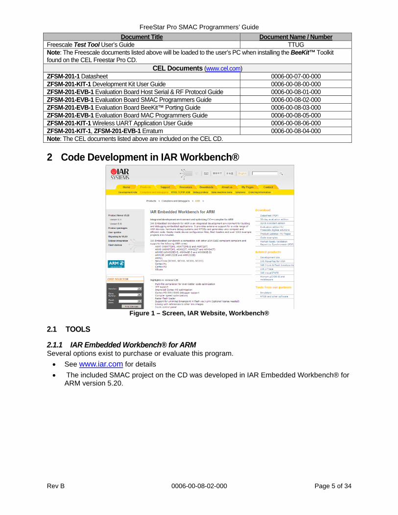
2 Code Development in IAR Workbench®
Figure 1 – Screen, IAR Website, Workbench®
2.1 TOOLS
2.1.1 IAR Embedded Workbench® for ARM Several options exist to purchase or evaluate this program.
See www.iar.com for details
The included SMAC project on the CD was developed in IAR Embedded Workbench® for ARM version 5.20.
FreeStar Pro SMAC Programmers’ Guide
Rev B 0006-00-08-02-000 Page 6 of 34
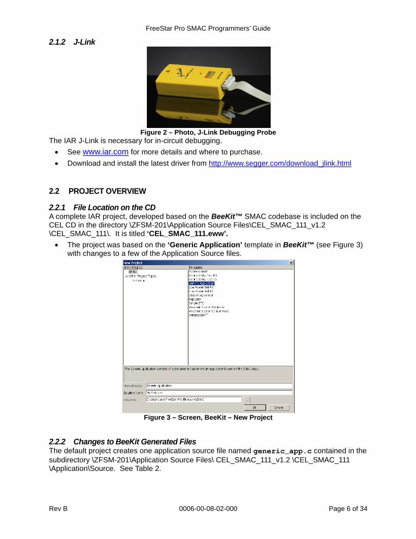
2.1.2 J-Link
Figure 2 – Photo, J-Link Debugging Probe
The IAR J-Link is necessary for in-circuit debugging.
See www.iar.com for more details and where to purchase.
Download and install the latest driver from http://www.segger.com/download_jlink.html
2.2 PROJECT OVERVIEW
2.2.1 File Location on the CD A complete IAR project, developed based on the BeeKit™ SMAC codebase is included on the CEL CD in the directory \ZFSM-201\Application Source Files\CEL_SMAC_111_v1.2 \CEL_SMAC_111\. It is titled ‘CEL_SMAC_111.eww’.
The project was based on the ‘Generic Application’ template in BeeKit™ (see Figure 3) with changes to a few of the Application Source files.
Figure 3 – Screen, BeeKit – New Project
2.2.2 Changes to BeeKit Generated Files The default project creates one application source file named generic_app.c contained in the subdirectory \ZFSM-201\Application Source Files\ CEL_SMAC_111_v1.2 \CEL_SMAC_111 \Application\Source. See Table 2.
FreeStar Pro SMAC Programmers’ Guide
Rev B 0006-00-08-02-000 Page 7 of 34
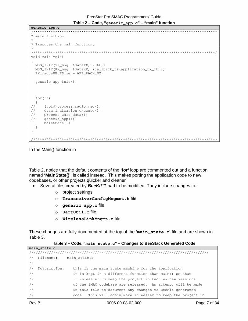
Table 2 – Code, “generic_app.c” – “main” function generic_app.c /************************************************************************************* main function * * Executes the main function. * ************************************************************************************/void Main(void) { MSG_INIT(TX_msg, &dataTX, NULL); MSG_INIT(RX_msg, &dataRX, (callback_t)(application_rx_cb)); RX_msg.u8BufSize = APP_PACK_SZ; generic_app_init(); for(;;) { // (void)process_radio_msg(); // data_indication_execute(); // process_uart_data(); // generic_app(); MainState(); } } /************************************************************************************
In the Main() function in Table 2, notice that the default contents of the ‘for’ loop are commented out and a function named ‘MainState()’; is called instead. This makes porting the application code to new codebases, or other projects quicker and cleaner. Several files created by BeeKit™ had to be modified. They include changes to:
o project settings
o TransceiverConfigMngmnt.h file
o generic_app.c file
o UartUtil.c file
o WirelessLinkMngmt.c file
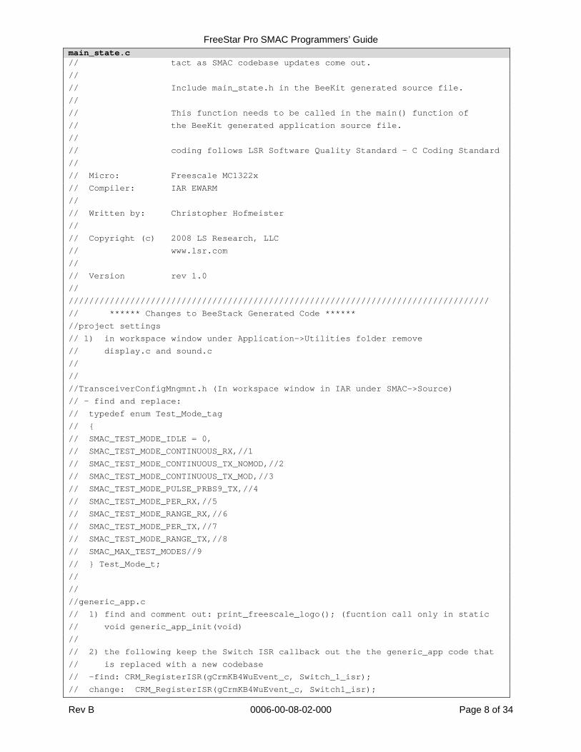
These changes are fully documented at the top of the ‘main_state.c’ file and are shown in Table 3.
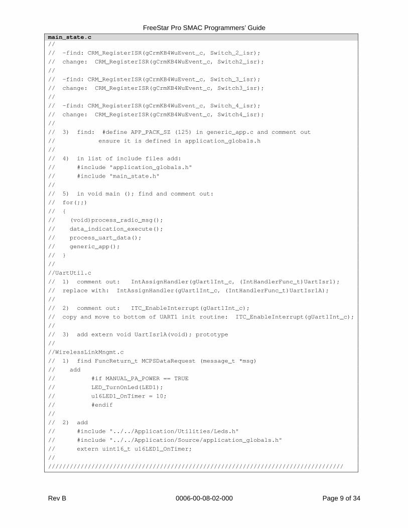
Table 3 – Code, “main_state.c” – Changes to BeeStack Generated Code main_state.c //////////////////////////////////////////////////////////////////////////////////
// Filename: main_state.c
//
// Description: this is the main state machine for the application
// it is kept in a different function than main() so that
// it is easier to keep the project in tact as new versions
// of the SMAC codebase are released. An attempt will be made
// in this file to document any changes to BeeKit generated
// code. This will again make it easier to keep the project in
FreeStar Pro SMAC Programmers’ Guide
Rev B 0006-00-08-02-000 Page 8 of 34
main_state.c // tact as SMAC codebase updates come out.
//
// Include main_state.h in the BeeKit generated source file.
//
// This function needs to be called in the main() function of
// the BeeKit generated application source file.
//
// coding follows LSR Software Quality Standard - C Coding Standard
//
// Micro: Freescale MC1322x
// Compiler: IAR EWARM
//
// Written by: Christopher Hofmeister
//
// Copyright (c) 2008 LS Research, LLC
// www.lsr.com
//
// Version rev 1.0
//
//////////////////////////////////////////////////////////////////////////////////
// ****** Changes to BeeStack Generated Code ******
//project settings
// 1) in workspace window under Application->Utilities folder remove
// display.c and sound.c
//
//
//TransceiverConfigMngmnt.h (In workspace window in IAR under SMAC->Source)
// - find and replace:
// typedef enum Test_Mode_tag
// {
// SMAC_TEST_MODE_IDLE = 0,
// SMAC_TEST_MODE_CONTINUOUS_RX,//1
// SMAC_TEST_MODE_CONTINUOUS_TX_NOMOD,//2
// SMAC_TEST_MODE_CONTINUOUS_TX_MOD,//3
// SMAC_TEST_MODE_PULSE_PRBS9_TX,//4
// SMAC_TEST_MODE_PER_RX,//5
// SMAC_TEST_MODE_RANGE_RX,//6
// SMAC_TEST_MODE_PER_TX,//7
// SMAC_TEST_MODE_RANGE_TX,//8
// SMAC_MAX_TEST_MODES//9
// } Test_Mode_t;
//
//
//generic_app.c
// 1) find and comment out: print_freescale_logo(); (fucntion call only in static
// void generic_app_init(void)
//
// 2) the following keep the Switch ISR callback out the the generic_app code that
// is replaced with a new codebase
// -find: CRM_RegisterISR(gCrmKB4WuEvent_c, Switch_1_isr);
// change: CRM_RegisterISR(gCrmKB4WuEvent_c, Switch1_isr);
FreeStar Pro SMAC Programmers’ Guide
Rev B 0006-00-08-02-000 Page 9 of 34
main_state.c //
// -find: CRM_RegisterISR(gCrmKB4WuEvent_c, Switch_2_isr);
// change: CRM_RegisterISR(gCrmKB4WuEvent_c, Switch2_isr);
//
// -find: CRM_RegisterISR(gCrmKB4WuEvent_c, Switch_3_isr);
// change: CRM_RegisterISR(gCrmKB4WuEvent_c, Switch3_isr);
//
// -find: CRM_RegisterISR(gCrmKB4WuEvent_c, Switch_4_isr);
// change: CRM_RegisterISR(gCrmKB4WuEvent_c, Switch4_isr);
//
// 3) find: #define APP_PACK_SZ (125) in generic_app.c and comment out
// ensure it is defined in application_globals.h
//
// 4) in list of include files add:
// #include "application_globals.h"
// #include "main_state.h"
//
// 5) in void main (); find and comment out:
// for(;;)
// {
// (void)process_radio_msg();
// data_indication_execute();
// process_uart_data();
// generic_app();
// }
//
//UartUtil.c
// 1) comment out: IntAssignHandler(gUart1Int_c, (IntHandlerFunc_t)UartIsr1);
// replace with: IntAssignHandler(gUart1Int_c, (IntHandlerFunc_t)UartIsr1A);
//
// 2) comment out: ITC_EnableInterrupt(gUart1Int_c);
// copy and move to bottom of UART1 init routine: ITC_EnableInterrupt(gUart1Int_c);
//
// 3) add extern void UartIsr1A(void); prototype
//
//WirelessLinkMngmt.c
// 1) find FuncReturn_t MCPSDataRequest (message_t *msg)
// add
// #if MANUAL_PA_POWER == TRUE
// LED_TurnOnLed(LED1);
// u16LED1_OnTimer = 10;
// #endif
//
// 2) add
// #include "../../Application/Utilities/Leds.h"
// #include "../../Application/Source/application_globals.h"
// extern uint16_t u16LED1_OnTimer;
//
//////////////////////////////////////////////////////////////////////////////////
FreeStar Pro SMAC Programmers’ Guide
Rev B 0006-00-08-02-000 Page 10 of 34
2.3 APPLICATION FILES
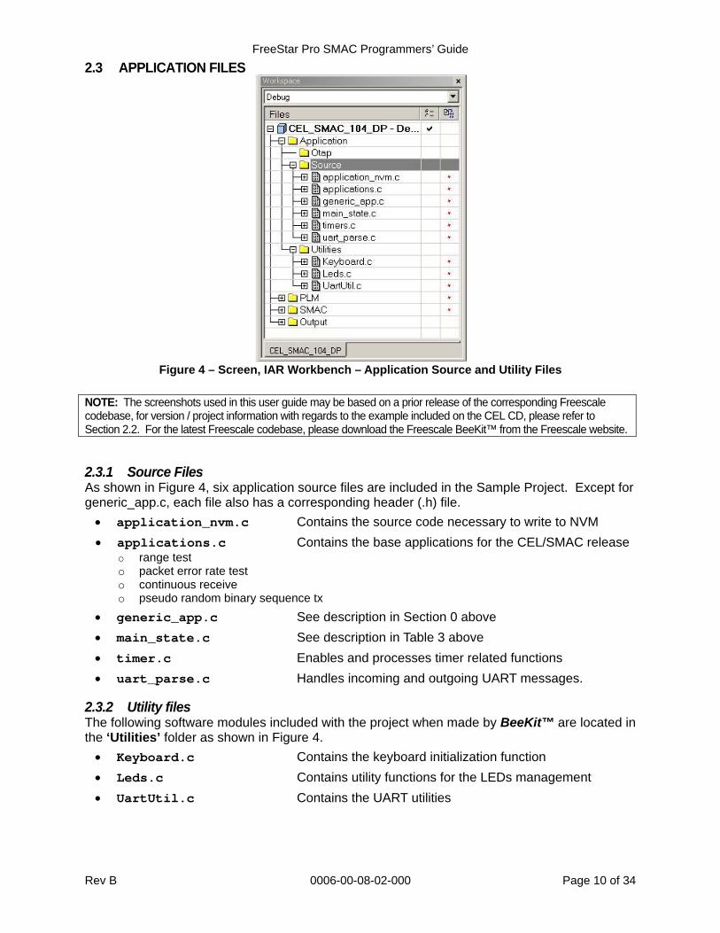
Figure 4 – Screen, IAR Workbench – Application Source and Utility Files
NOTE: The screenshots used in this user guide may be based on a prior release of the corresponding Freescale codebase, for version / project information with regards to the example included on the CEL CD, please refer to Section 2.2. For the latest Freescale codebase, please download the Freescale BeeKit™ from the Freescale website.
2.3.1 Source Files As shown in Figure 4, six application source files are included in the Sample Project. Except for generic_app.c, each file also has a corresponding header (.h) file.
application_nvm.c Contains the source code necessary to write to NVM
applications.c Contains the base applications for the CEL/SMAC release o range test o packet error rate test o continuous receive o pseudo random binary sequence tx
generic_app.c See description in Section 0 above
main_state.c See description in Table 3 above
timer.c Enables and processes timer related functions
uart_parse.c Handles incoming and outgoing UART messages.
2.3.2 Utility files The following software modules included with the project when made by BeeKit™ are located in the ‘Utilities’ folder as shown in Figure 4.
Keyboard.c Contains the keyboard initialization function
Leds.c Contains utility functions for the LEDs management
UartUtil.c Contains the UART utilities
FreeStar Pro SMAC Programmers’ Guide
Rev B 0006-00-08-02-000 Page 11 of 34
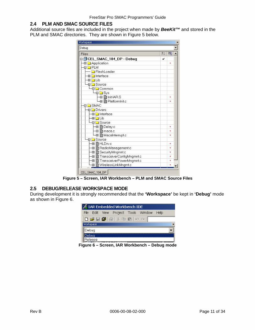
2.4 PLM AND SMAC SOURCE FILES Additional source files are included in the project when made by BeeKit™ and stored in the PLM and SMAC directories. They are shown in Figure 5 below.
Figure 5 – Screen, IAR Workbench – PLM and SMAC Source Files
2.5 DEBUG/RELEASE WORKSPACE MODE During development it is strongly recommended that the ‘Workspace’ be kept in ‘Debug’ mode as shown in Figure 6.
Figure 6 – Screen, IAR Workbench – Debug mode
FreeStar Pro SMAC Programmers’ Guide
Rev B 0006-00-08-02-000 Page 12 of 34
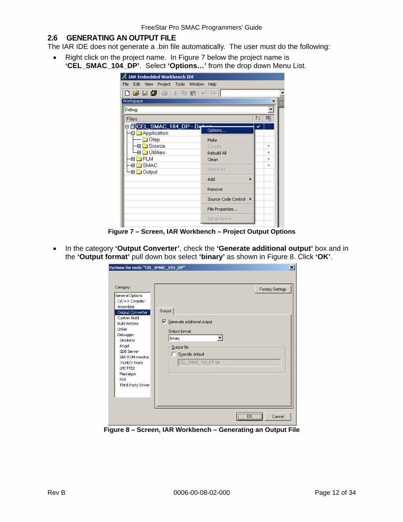
2.6 GENERATING AN OUTPUT FILE The IAR IDE does not generate a .bin file automatically. The user must do the following:
Right click on the project name. In Figure 7 below the project name is ‘CEL_SMAC_104_DP’. Select ‘Options…’ from the drop down Menu List.
Figure 7 – Screen, IAR Workbench – Project Output Options
In the category ‘Output Converter’, check the ‘Generate additional output’ box and in
the ‘Output format’ pull down box select ‘binary’ as shown in Figure 8. Click ‘OK’.
Figure 8 – Screen, IAR Workbench – Generating an Output File
FreeStar Pro SMAC Programmers’ Guide
Rev B 0006-00-08-02-000 Page 13 of 34
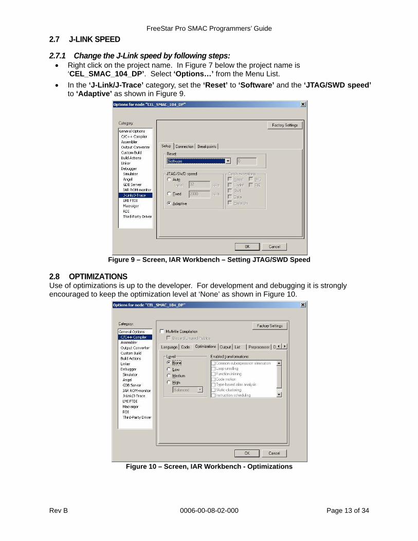
2.7 J-LINK SPEED
2.7.1 Change the J-Link speed by following steps: Right click on the project name. In Figure 7 below the project name is
‘CEL_SMAC_104_DP’. Select ‘Options…’ from the Menu List.
In the ‘J-Link/J-Trace’ category, set the ‘Reset’ to ‘Software’ and the ‘JTAG/SWD speed’ to ‘Adaptive’ as shown in Figure 9.
Figure 9 – Screen, IAR Workbench – Setting JTAG/SWD Speed
2.8 OPTIMIZATIONS Use of optimizations is up to the developer. For development and debugging it is strongly encouraged to keep the optimization level at ‘None’ as shown in Figure 10.
Figure 10 – Screen, IAR Workbench - Optimizations
FreeStar Pro SMAC Programmers’ Guide
Rev B 0006-00-08-02-000 Page 14 of 34
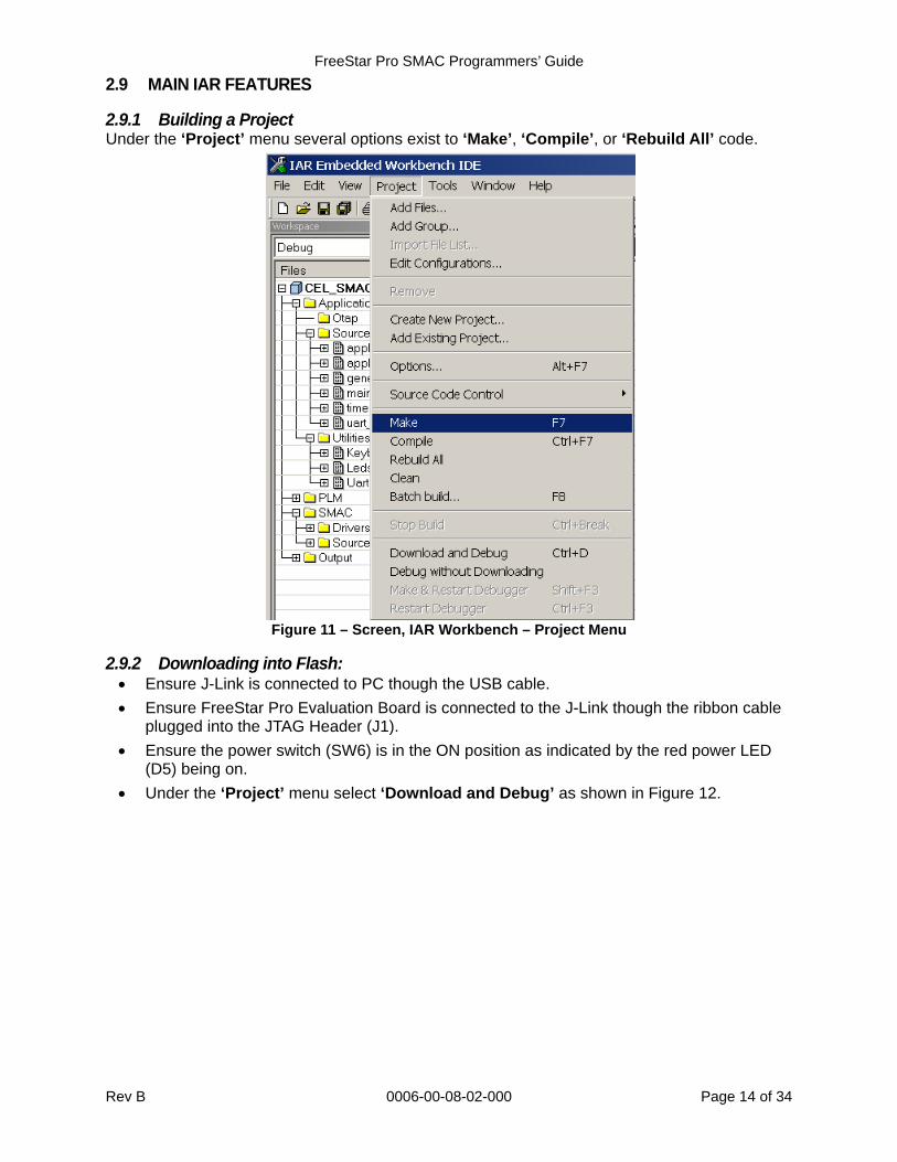
2.9 MAIN IAR FEATURES
2.9.1 Building a Project Under the ‘Project’ menu several options exist to ‘Make’, ‘Compile’, or ‘Rebuild All’ code.
Figure 11 – Screen, IAR Workbench – Project Menu
2.9.2 Downloading into Flash: Ensure J-Link is connected to PC though the USB cable.
Ensure FreeStar Pro Evaluation Board is connected to the J-Link though the ribbon cable plugged into the JTAG Header (J1).
Ensure the power switch (SW6) is in the ON position as indicated by the red power LED (D5) being on.
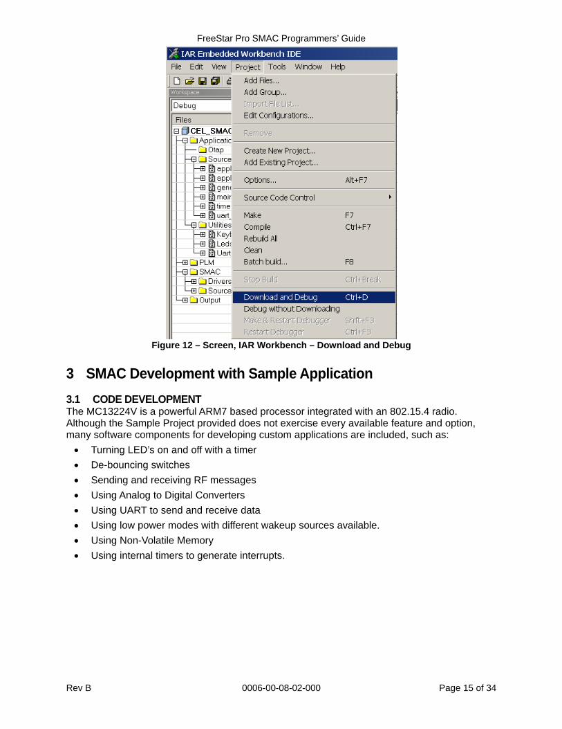
Under the ‘Project’ menu select ‘Download and Debug’ as shown in Figure 12.
FreeStar Pro SMAC Programmers’ Guide
Rev B 0006-00-08-02-000 Page 15 of 34
Figure 12 – Screen, IAR Workbench – Download and Debug
3 SMAC Development with Sample Application
3.1 CODE DEVELOPMENT The MC13224V is a powerful ARM7 based processor integrated with an 802.15.4 radio. Although the Sample Project provided does not exercise every available feature and option, many software components for developing custom applications are included, such as:
Turning LED’s on and off with a timer
De-bouncing switches
Sending and receiving RF messages
Using Analog to Digital Converters
Using UART to send and receive data
Using low power modes with different wakeup sources available.
Using Non-Volatile Memory
Using internal timers to generate interrupts.
FreeStar Pro SMAC Programmers’ Guide
Rev B 0006-00-08-02-000 Page 16 of 34
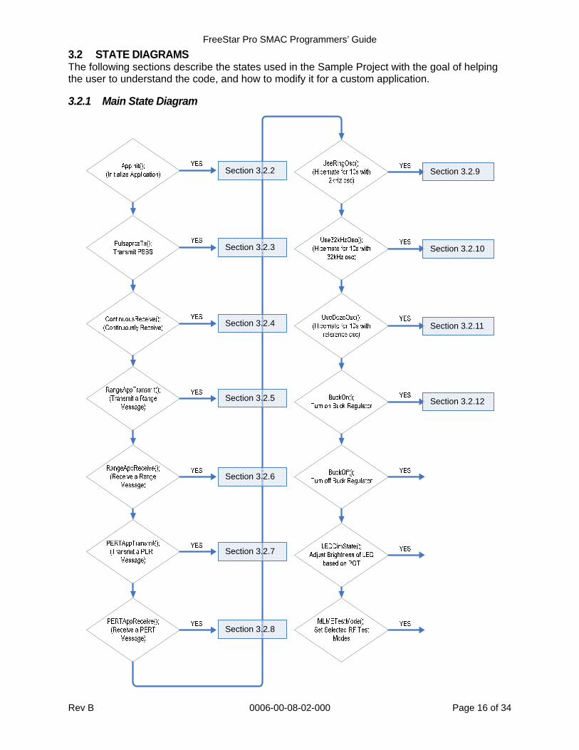
3.2 STATE DIAGRAMS The following sections describe the states used in the Sample Project with the goal of helping the user to understand the code, and how to modify it for a custom application.
3.2.1 Main State Diagram
Section 3.2.5 Section 3.2.12
Section 3.2.2
Section 3.2.3
Section 3.2.4
Section 3.2.6
Section 3.2.7
Section 3.2.8
Section 3.2.9
Section 3.2.10
Section 3.2.11
FreeStar Pro SMAC Programmers’ Guide
Rev B 0006-00-08-02-000 Page 17 of 34
Figure 13 – Diagram, Main State
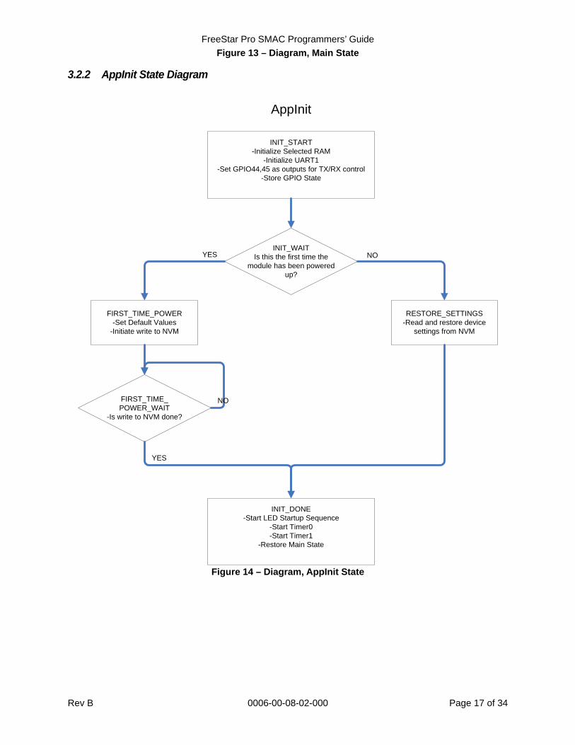
3.2.2 AppInit State Diagram
INIT_WAITIs this the first time the
module has been powered up?
YES
AppInit
INIT_START-Initialize Selected RAM
-Initialize UART1-Set GPIO44,45 as outputs for TX/RX control
-Store GPIO State
FIRST_TIME_POWER-Set Default Values
-Initiate write to NVM
RESTORE_SETTINGS-Read and restore device
settings from NVM
NO
FIRST_TIME_POWER_WAIT
-Is write to NVM done?
NO
INIT_DONE-Start LED Startup Sequence
-Start Timer0-Start Timer1
-Restore Main State
YES
Figure 14 – Diagram, AppInit State
FreeStar Pro SMAC Programmers’ Guide
Rev B 0006-00-08-02-000 Page 18 of 34
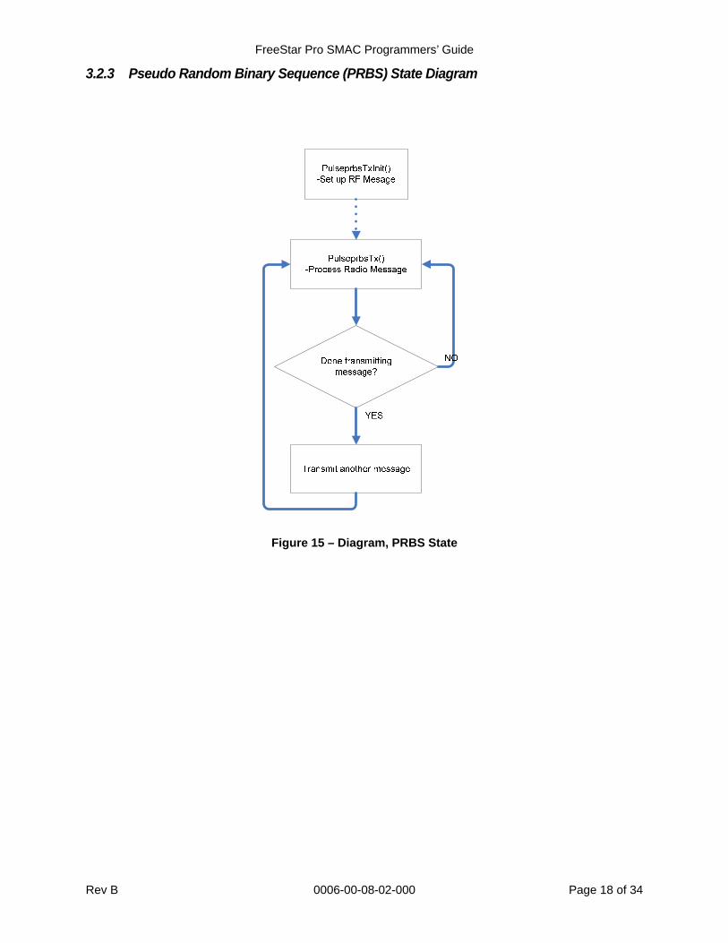
3.2.3 Pseudo Random Binary Sequence (PRBS) State Diagram
Figure 15 – Diagram, PRBS State
FreeStar Pro SMAC Programmers’ Guide
Rev B 0006-00-08-02-000 Page 19 of 34
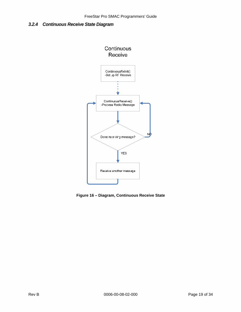
3.2.4 Continuous Receive State Diagram
Figure 16 – Diagram, Continuous Receive State
FreeStar Pro SMAC Programmers’ Guide
Rev B 0006-00-08-02-000 Page 20 of 34
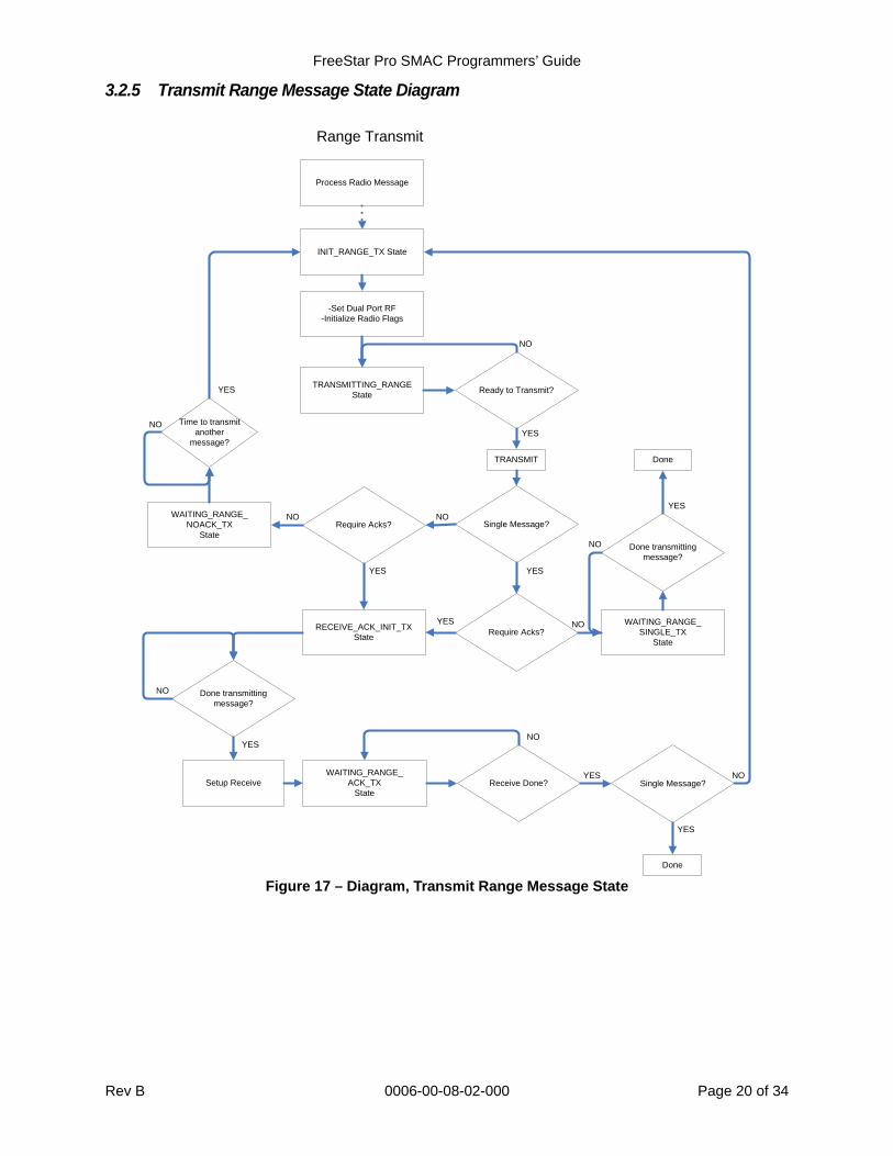
3.2.5 Transmit Range Message State Diagram
Range Transmit
Process Radio Message
NO
INIT_RANGE_TX State
TRANSMITTING_RANGE State
RECEIVE_ACK_INIT_TX State
WAITING_RANGE_ACK_TX
State
WAITING_RANGE_NOACK_TX
State
WAITING_RANGE_SINGLE_TX
State
-Set Dual Port RF-Initialize Radio Flags
Ready to Transmit?
Single Message?
Require Acks?
YES
YES
Require Acks?NO
YES
NO
Time to transmit another
message?
YES
NO
YES
Done transmitting message?
Setup Receive
YES
NO
Receive Done? Single Message?YES
NO
NO
Done
Done
Done transmitting message?
NO
YES
TRANSMIT
NO
YES
NO
Figure 17 – Diagram, Transmit Range Message State
FreeStar Pro SMAC Programmers’ Guide
Rev B 0006-00-08-02-000 Page 21 of 34
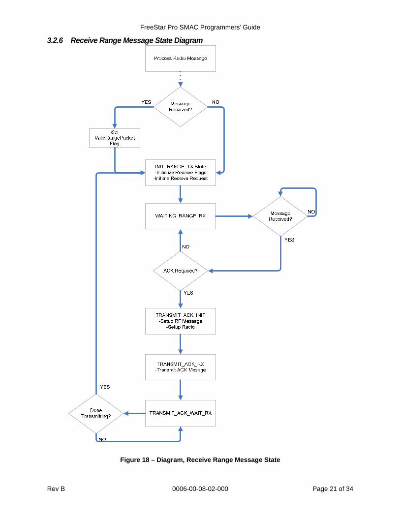
3.2.6 Receive Range Message State Diagram
Figure 18 – Diagram, Receive Range Message State
FreeStar Pro SMAC Programmers’ Guide
Rev B 0006-00-08-02-000 Page 22 of 34
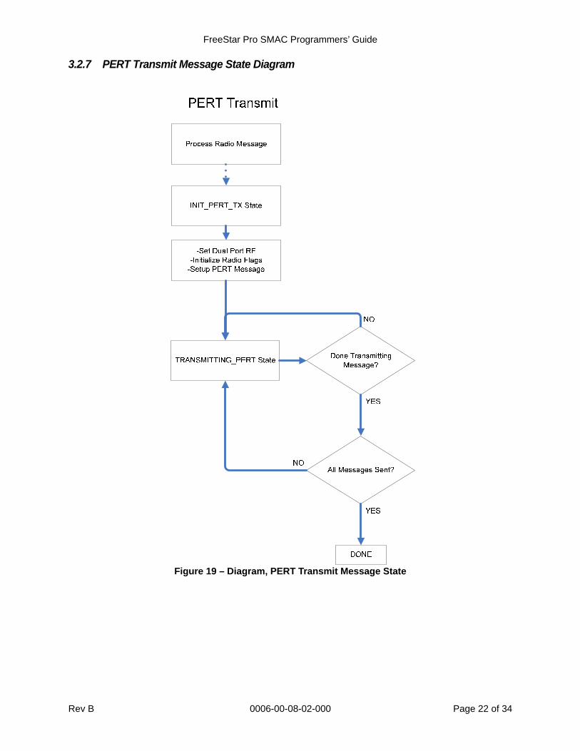
3.2.7 PERT Transmit Message State Diagram
Figure 19 – Diagram, PERT Transmit Message State
FreeStar Pro SMAC Programmers’ Guide
Rev B 0006-00-08-02-000 Page 23 of 34
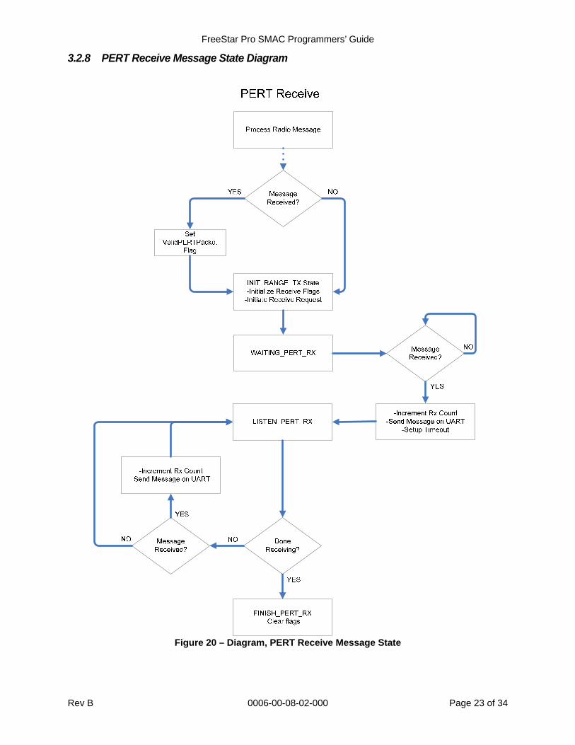
3.2.8 PERT Receive Message State Diagram
Figure 20 – Diagram, PERT Receive Message State
FreeStar Pro SMAC Programmers’ Guide
Rev B 0006-00-08-02-000 Page 24 of 34
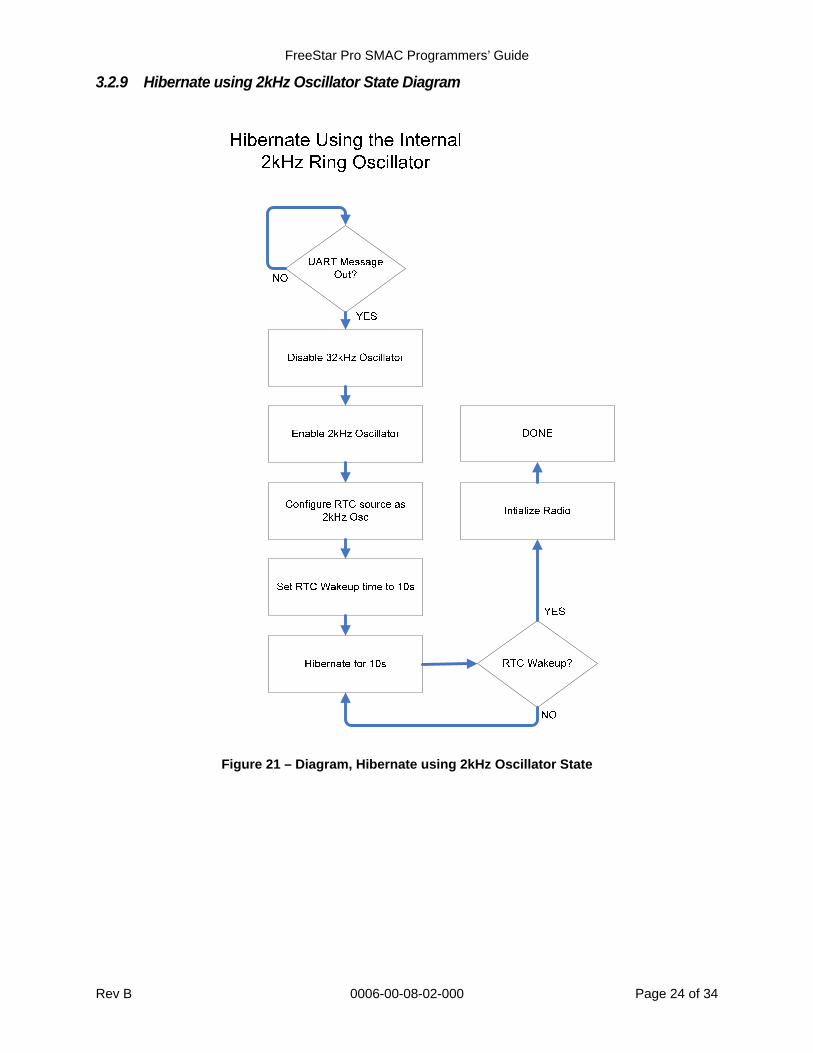
3.2.9 Hibernate using 2kHz Oscillator State Diagram
Figure 21 – Diagram, Hibernate using 2kHz Oscillator State
FreeStar Pro SMAC Programmers’ Guide
Rev B 0006-00-08-02-000 Page 25 of 34
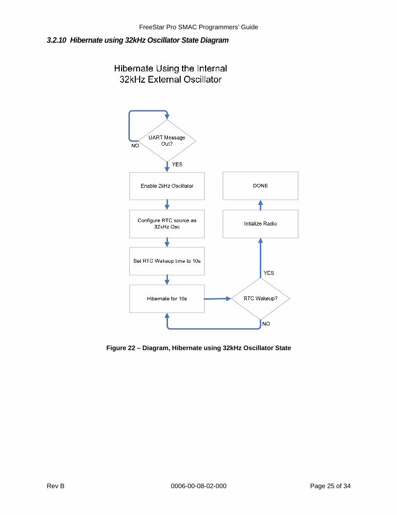
3.2.10 Hibernate using 32kHz Oscillator State Diagram
Figure 22 – Diagram, Hibernate using 32kHz Oscillator State
FreeStar Pro SMAC Programmers’ Guide
Rev B 0006-00-08-02-000 Page 26 of 34
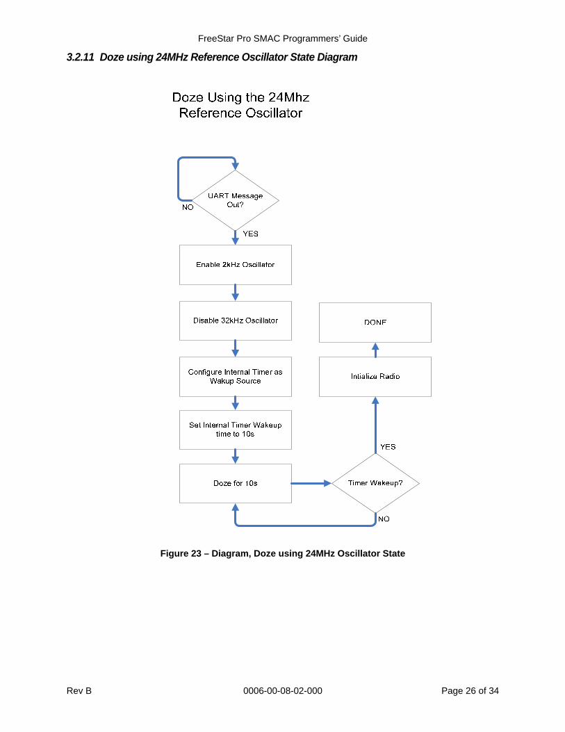
3.2.11 Doze using 24MHz Reference Oscillator State Diagram
Figure 23 – Diagram, Doze using 24MHz Oscillator State
FreeStar Pro SMAC Programmers’ Guide
Rev B 0006-00-08-02-000 Page 27 of 34
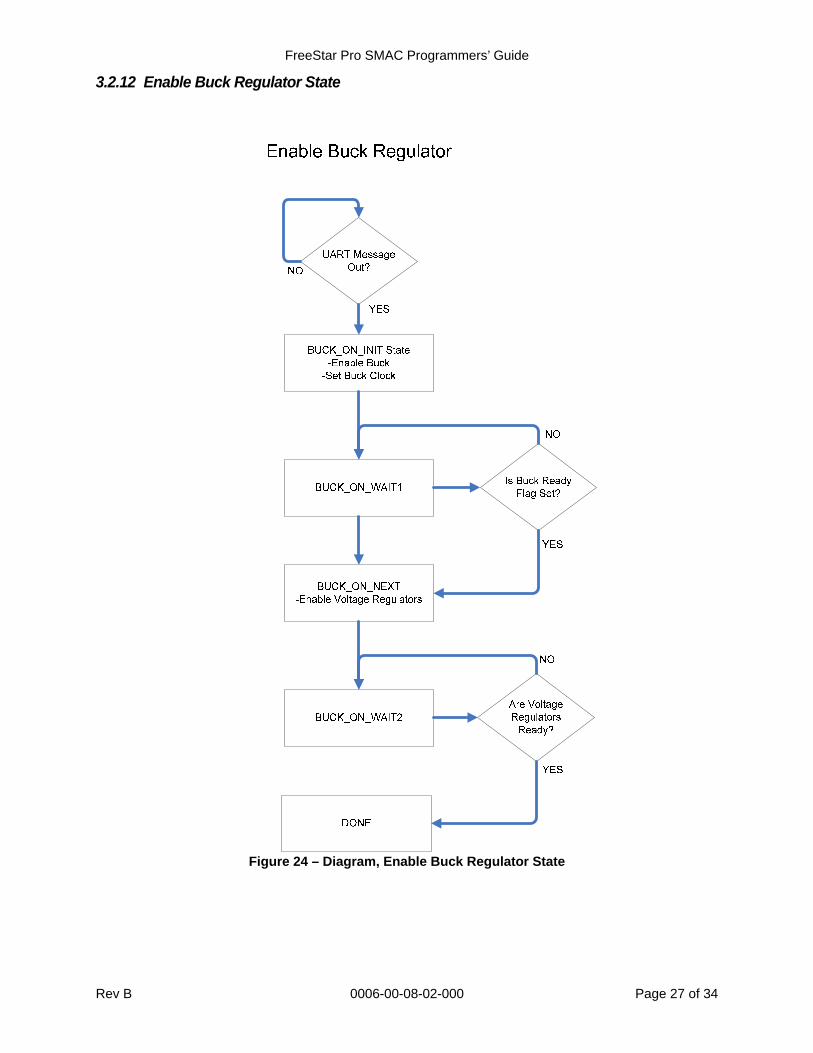
3.2.12 Enable Buck Regulator State
Figure 24 – Diagram, Enable Buck Regulator State
FreeStar Pro SMAC Programmers’ Guide
Rev B 0006-00-08-02-000 Page 28 of 34
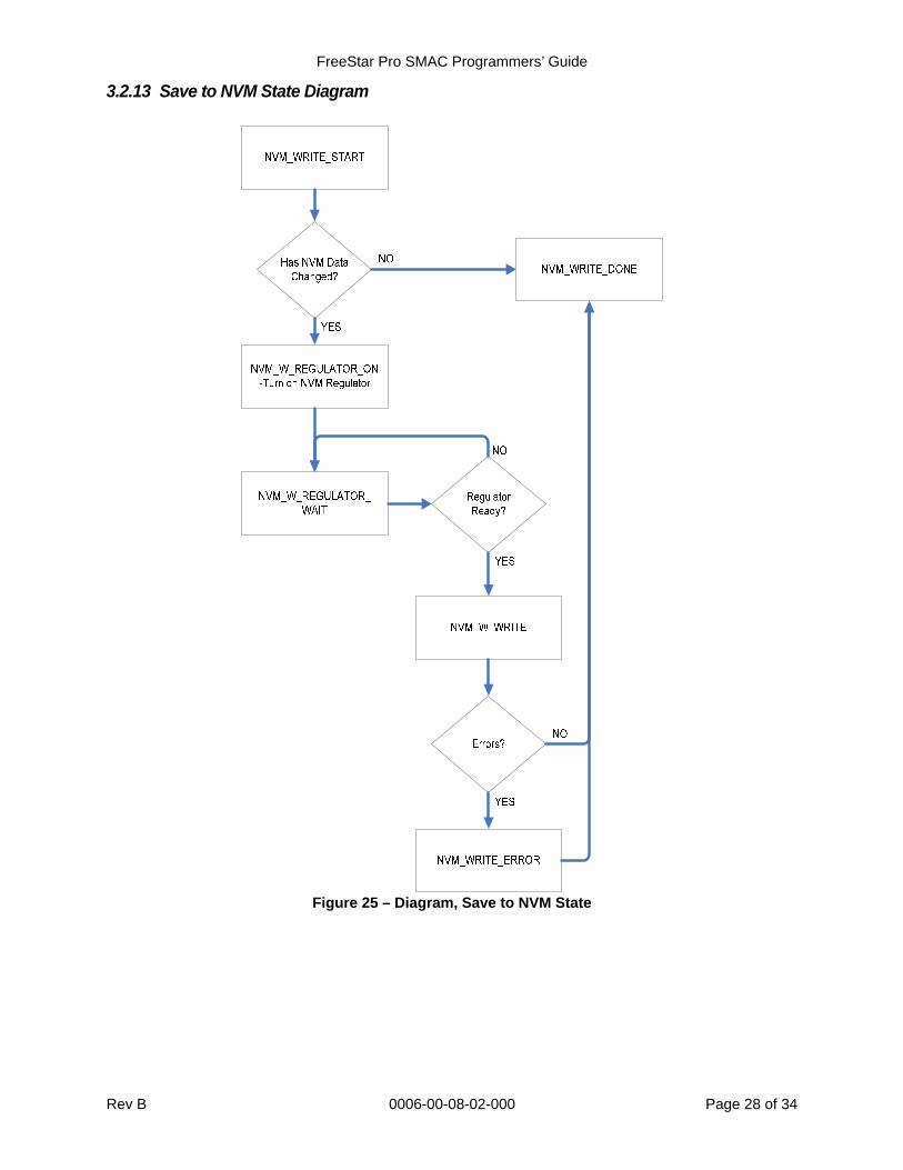
3.2.13 Save to NVM State Diagram
Figure 25 – Diagram, Save to NVM State
FreeStar Pro SMAC Programmers’ Guide
Rev B 0006-00-08-02-000 Page 29 of 34
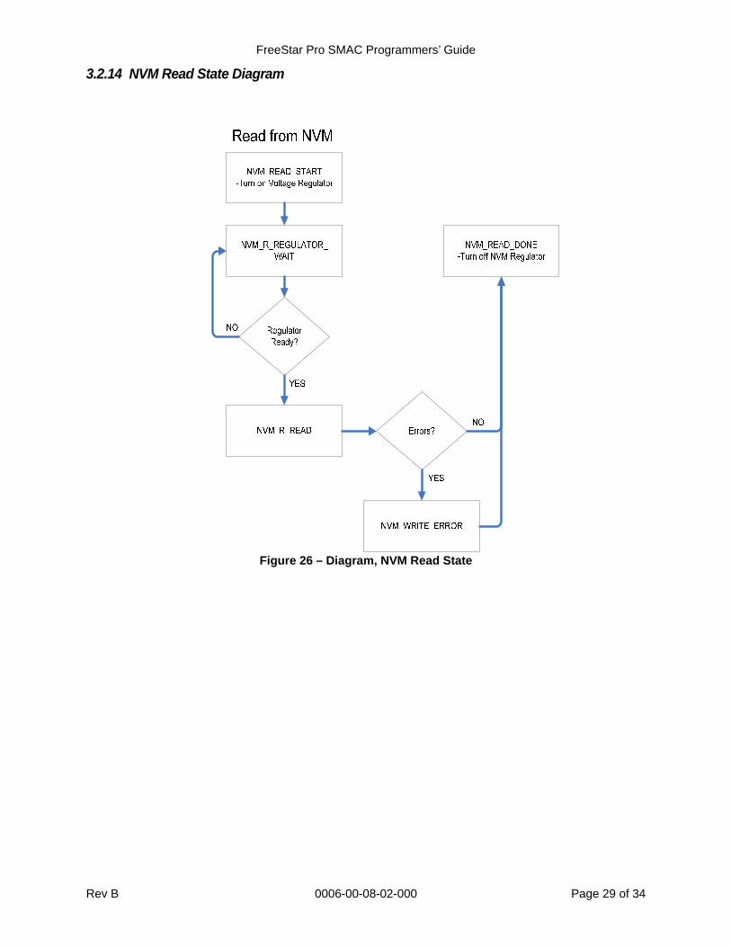
3.2.14 NVM Read State Diagram
Figure 26 – Diagram, NVM Read State
FreeStar Pro SMAC Programmers’ Guide
Rev B 0006-00-08-02-000 Page 30 of 34
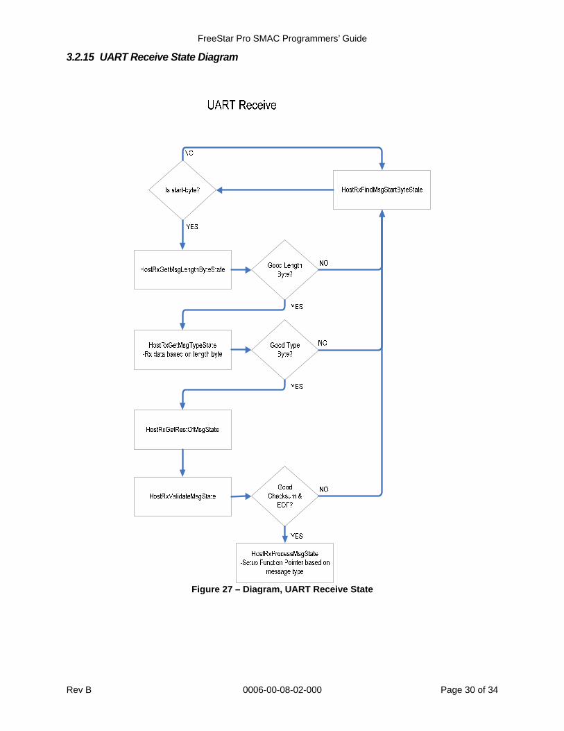
3.2.15 UART Receive State Diagram
Figure 27 – Diagram, UART Receive State
FreeStar Pro SMAC Programmers’ Guide
Rev B 0006-00-08-02-000 Page 31 of 34
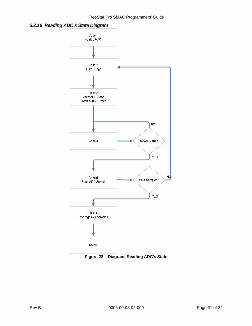
3.2.16 Reading ADC’s State Diagram
Figure 28 – Diagram, Reading ADC’s State
FreeStar Pro SMAC Programmers’ Guide
Rev B 0006-00-08-02-000 Page 32 of 34
3.3 TRANSMITTING AN RF MESSAGE
3.3.1 More information See Freescale documents “Simple Media Access Controller (SMAC) User’s Guide” (Freescale Doc # SMACRM) and “MC1322x Simple Media Access Controller (SMAC) Reference Manual” (Freescale Doc # 22xSMACRM) for more information.
The Tx_msg structure contains a pointer to the Transmit Buffer named dataTx. These are setup by BeeKit™ and are declared in generic_app.c if using the SMAC Sample Project contained on the CD.
Setup the size of the Message by setting the TX.msg.u8BufSize to the size of the message.
Copy the message to transmit into the dataTx buffer using the Tx_msg structure and pointer. For an example see the SetupRFTxMessage() function in applications.c. The function is setting up a message that matches the CEL SMAC RF Protocol that is defined in the “ZFSM-201-EVB-1 Evaluation Board Host Serial & RF Protocol Guide” (CEL Doc #0006-00-08-01-000).
Initiate a request to transmit using the SMAC API MCPSDataRequest(&TX_msg). See the RangeAppTransmit() function in applications.c for an example.
The (void) process_radio_msg() must be routinely called to run the radio state machine. It is the first function called in the RangeAppTransmit() function in applications.c.
Before attempting to transmit or receive another RF message ensure the first message was transmitted. Use the (s_tx_msg_final_state(TX_msg) macro to tell when the device is done transmitting the message. This macro only looks at the end result, not what happened. Further coding could be done by the application to track the status of the message and verify complete success. See the RangeAppTransmit() function in applications.c.
3.4 RECEIVING AN RF MESSAGE
3.4.1 More information See Freescale documents “Simple Media Access Controller (SMAC) User’s Guide” (Freescale Doc # SMACRM) and “MC1322x Simple Media Access Controller (SMAC) Reference Manual” (Freescale Doc # 22xSMACRM) for more information.
The Rx_msg structure contains a pointer to the Receive Buffer named dataRx. These are setup by BeeKit™ and are declared in generic_app.c if using the SMAC Sample Project contained on the CD.
A receive buffer size and callback function for when data is received must be setup. These are setup by BeeKit™ and are seen in generic_app.c in the main() function if using the SMAC Sample Project contained on the CD.
Initiate a request to transmit using the SMAC API MLMERXEnableRequest(&RX_msg, 0x00000000). See the RangeAppReceive() function in applications.c for an example.
Use the is_rx_msg_final_state(RX_msg) macro to tell when the device is done trying to receive a message. This macro only looks at the end result, not what happened. Further coding could be done by the application to track the status of the receive state machine. See RangeAppReceive() function in applications.c for an example.
The callback function, in the SMAC Sample Project contained on the CD, calls the void application_rx_cb (void) if RF data is received. This function does not validate the data, nor indicate a VALID message. It simply sets the gbDataIndicationFlag to ‘TRUE’. It is up to the application to check this flag and validate the RF message.
FreeStar Pro SMAC Programmers’ Guide
Rev B 0006-00-08-02-000 Page 33 of 34
The process_radio_msg() function must be routinely called to run the radio state machine. It is the first function called in the RangeAppReceive() function in applications.c.
3.5 CHANGING OR QUERYING THE RF CHANNEL
3.5.1 More information See Freescale documents “Simple Media Access Controller (SMAC) User’s Guide” (Freescale Doc # SMACRM) and “MC1322x Simple Media Access Controller (SMAC) Reference Manual” (Freescale Doc # 22xSMACRM) for more information.
The SMAC codebase contains an API to change the channel named MLMESetChannelRequest().
The SMAC API called MLMEGetChannelRequest() can be used to read the current RF channel.
When a request to change the channel is received on the UART the ChangeChannel() function is used. It is found in main_state.c. The function checks the data range of the received UART data and uses both of the SMAC API’s to check and change the channel.
3.6 CHANGING THE RF POWER
3.6.1 More information See Freescale documents “Simple Media Access Controller (SMAC) User’s Guide” (Freescale Doc # SMACRM) and “MC1322x Simple Media Access Controller (SMAC) Reference Manual” (Freescale Doc # 22xSMACRM) for more information.
The SMAC codebase contains an API to change the power named MLMEPAOutputAdjust(). It is called in the ChangePower() function in the main_state.c.
For example, this ChangePower() function is used in the SetManualRangeTx() function in applications.c.
3.7 RECEIVING A UART MESSAGE UART messages are parsed as they are received with the use of function pointers.
Each state of the function checks for valid data (start byte, message type, checksum and end-of-frame).
If a valid UART message is received another function pointer is set up based on the message Type.
This function will respond as appropriate for the message type and received data.
See uart_parse.c
3.8 TRANSMITTING A UART MESSAGE The MC13224V has an internal 32-byte transmit buffer.
Data is fed into the buffer and as interrupts occur, the application code waits for the buffer to empty.
See uart_parse.c and the UartIsr1A function in main_state.c

FreeStar Pro SMAC Programmers’ Guide
Rev B 0006-00-08-02-000 Page 34 of 34
3.9 TIMERS A variety of options exist on the MC13224V for periodic timers that expire and generate an interrupt.
The sample SMAC project on the CD uses Timer0 to generate an interrupt every 5mS.
See timers.c for setup and usage.
A variety of the other timers based on Timer0 can be set up and updated every time Timer0 expires. See the UpdateTimer0() function in main_state.c.
3.10 EVENTS Low priority events (turn LED’s off, responding to switches) are handled in the EventDo()
function in main_state.c.
Other events can be easily added.
3.11 READING ADC’S Two A/D converters are connected to Potentiometers on the CEL ZFSM-201-EVB-1
FreeStar Pro Evaluation Board.
Another A/D internal to the MC13224V can be used to monitor the battery voltage.
It is important to monitor the battery voltage when the Buck Regulator is active. If the battery voltage falls below 2.5V the Buck needs to be placed in bypass mode. See Freescale Semiconductors’ “MC1322x Reference Manual” (Freescale Doc # MC1322xRM).
When a GUI message is received to query the A/D channels a Timer is set up to read the A/D’s every 500mS.
The ADC_Setup() function in main_state.c sets up the A/D’s.
Although the battery is used as the A/D reference, its value is based on an internal 1.2V reference.
Value read back by the 9th A/D input (battery) is actually a 1.20V reference.
To obtain the actual power supply use the following formula:
o Power Supply Voltage = (4095*1.20)/Power Supply A/D result
This ‘adjusted’ Power Supply Value can be used to improve the accuracy of the A/D values obtained from the power supply.
o ADC Voltage = (A/D result /4095) * Power Supply Voltage
3.12 USER INPUTS (SWITCHES) When an interrupt is detected on a switch, a 25mS Timer based off Timer0 is started.
Upon expiration the switch input to the MC13224V is read. If it is low (pressed) a valid switch press flag is set. The EventDo() function in main_state.c will respond to the switch event.
4 REVISION HISTORY Revision Date Description
Preliminary 28Oct08 Preliminary Release
A 04Feb09 Updated Table #1
B 22May09 Updated for BeeKit v1.9.5 / SMAC v1.11 Release