Embed Size (px)
Citation preview
Published: Feb 12, 2009
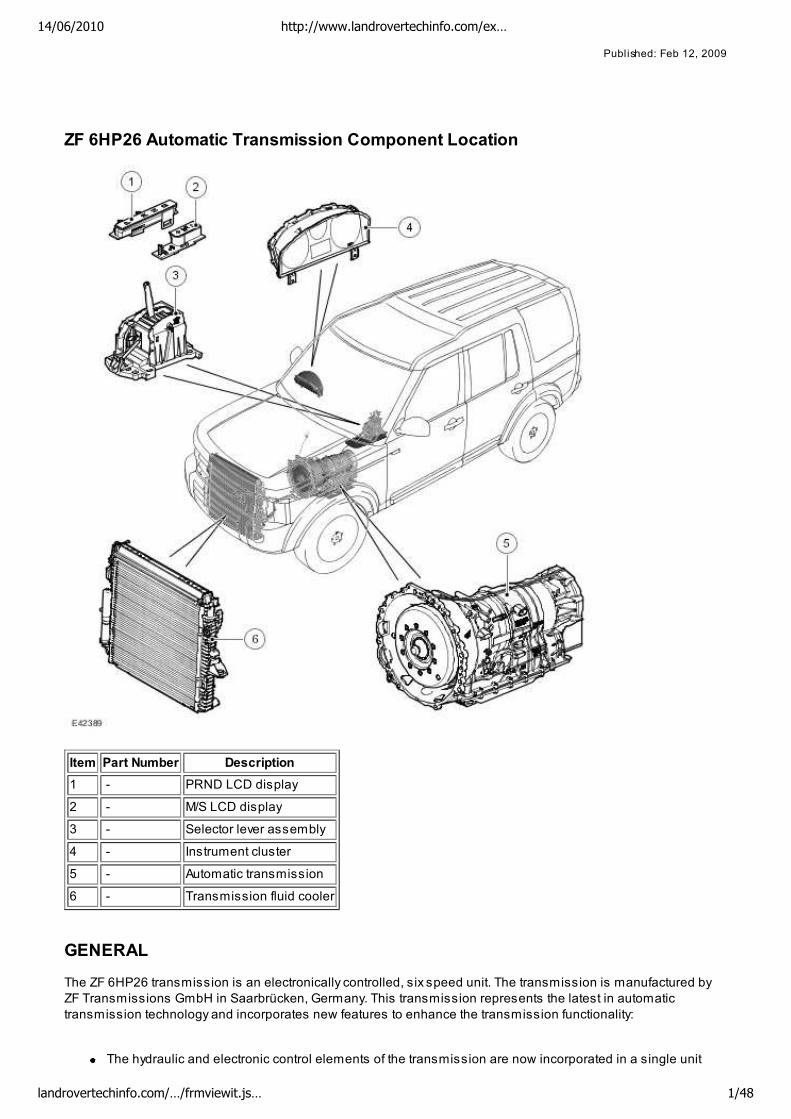
ZF 6HP26 Automatic Transmission Component Location
Item Part Number Description
1 - PRND LCD display
2 - M/S LCD display
3 - Selector lever assembly
4 - Instrument cluster
5 - Automatic transmission
6 - Transmission fluid cooler
GENERAL
The ZF 6HP26 transmission is an electronically controlled, six speed unit. The transmission is manufactured by
ZF Transmissions GmbH in Saarbrücken, Germany. This transmission represents the latest in automatic
transmission technology and incorporates new features to enhance the transmission functionality:
The hydraulic and electronic control elements of the transmission are now incorporated in a single unit
14/06/2010 http://www.landrovertechinfo.com/ex…
landrovertechinfo.com/…/frmviewit.js… 1/48
located inside the transmission and is known as 'Mechatronic'
Another new strategy is Adaptive Shift Strategy (ASIS). ASIS represents the continuous adaptation of shift
changes to suit the driving style of the driver which can vary from sporting to economical. Further details of
the ASIS function are contained in the 'Driving Modes' section.
The transmission is controlled by an Transmission Control Module (TCM) which contains software to provide
operation as a semi-automatic 'CommandShift™' transmission. The TCM allows the transmission to be operated
as a conventional automatic unit by selecting P, R, N, D on the selector lever. Movement of the selector lever
across the gate to the 'M/S' position puts the transmission into electronic 'Sport' mode. Further movement of the
lever in a lateral direction to the + or – position puts the transmission into electronic manual 'CommandShift™'
mode.
The 6HP26 transmission has the following features:
Designed to be maintenance free
Transmission fluid is 'fill for life'
The torque converter features a controlled slip feature with electronically regulated control of lock-up,
creating a smooth transition to the fully locked condition
Shift programs controlled by the TCM
Connected to the ECM via the High Speed CAN for communications
Default mode if major faults occur
Diagnostics available from the TCM via the CAN.
ZF 6HP26 Automatic Transmission – Exploded View
NOTE:
The transmission shown is exploded to the extent of the serviceable items
14/06/2010 http://www.landrovertechinfo.com/ex…
landrovertechinfo.com/…/frmviewit.js… 2/48
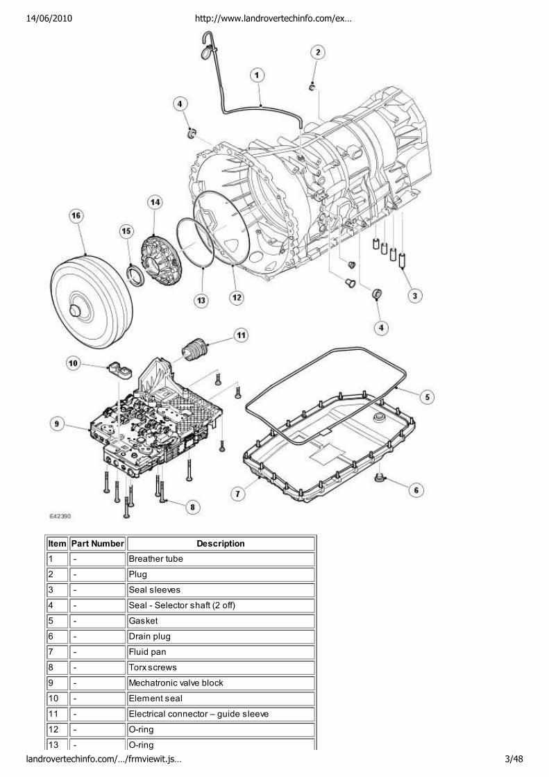
Item Part Number Description
1 - Breather tube
2 - Plug
3 - Seal sleeves
4 - Seal - Selector shaft (2 off)
5 - Gasket
6 - Drain plug
7 - Fluid pan
8 - Torx screws
9 - Mechatronic valve block
10 - Element seal
11 - Electrical connector – guide sleeve
12 - O-ring
13 - O-ring
14/06/2010 http://www.landrovertechinfo.com/ex…
landrovertechinfo.com/…/frmviewit.js… 3/48
14 - Pump housing (not a serviceable component)
15 - Input shaft seal
16 - Torque converter
The gearbox comprises the main casing which houses all of the transmission components. The main case also
incorporates an integral bell housing.
A fluid pan is bolted to the lower face of the main case and is secured with bolts. The fluid pan is sealed to the
main case with a gasket. Removal of the fluid pan allows access to the Mechatronic valve block. The fluid pan has
a magnet located around the drain plug which collects any metallic particles present in the transmission fluid.
A fluid filter is located inside the fluid pan. If the transmission fluid becomes contaminated or after any service
work, the fluid pan with integral filter must be replaced.
CAUTION: Take care when removing the fluid pan and/or replacing the Mechatronic valve block that
neither the fluid pan gasket or the mating face on the transmission casing is damaged or leakage may occur.
Do not use metal tools to prise the fluid pan from the transmission casing. Take care when positioning a new
mechatronic unit to ensure it does not contact the casing face.
The integral bell housing provides protection for the torque converter assembly and also provides the attachment
for the gearbox to the engine cylinder block. The torque converter is a non-serviceable assembly which also
contains the lock-up clutch mechanism. The torque converter drives a crescent type pump via drive tangs. The fluid
pump is located in the main case, behind the torque converter.
The main case contains the following major components:
Input shaft
Output shaft
Mechatronic valve block which contains the solenoids, speed sensors and the TCM
Three rotating multiplate drive clutches
Two fixed multiplate brake clutches
A single planetary gear train and a double planetary gear train.
ZF 6HP26 Automatic Transmission – Sectional View
14/06/2010 http://www.landrovertechinfo.com/ex…
landrovertechinfo.com/…/frmviewit.js… 4/48
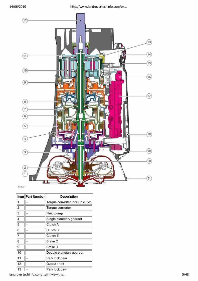
Item Part Number Description
1 - Torque converter lock-up clutch
2 - Torque converter
3 - Fluid pump
4 - Single planetary gearset
5 - Clutch A
6 - Clutch B
7 - Clutch E
8 - Brake C
9 - Brake D
10 - Double planetary gearset
11 - Park lock gear
12 - Output shaft
13 - Park lock pawl
14/06/2010 http://www.landrovertechinfo.com/ex…
landrovertechinfo.com/…/frmviewit.js… 5/48
14 - Drain plug
15 - Magnet
16 - Pressure regulator
17 - Mechatronic valve block
18 - Fluid filter
19 - Fluid pan
20 - Input shaft
21 - Transmission casing
TORQUE CONVERTER
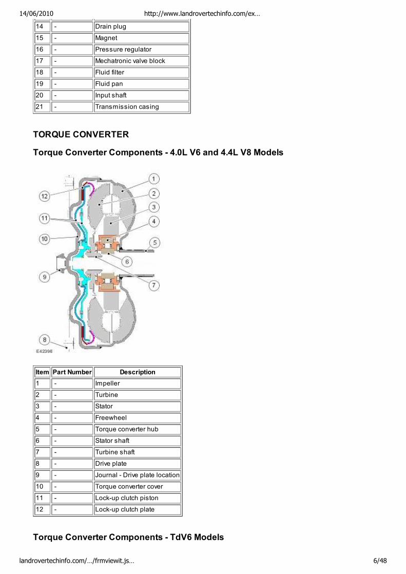
Torque Converter Components - 4.0L V6 and 4.4L V8 Models
Item Part Number Description
1 - Impeller
2 - Turbine
3 - Stator
4 - Freewheel
5 - Torque converter hub
6 - Stator shaft
7 - Turbine shaft
8 - Drive plate
9 - Journal - Drive plate location
10 - Torque converter cover
11 - Lock-up clutch piston
12 - Lock-up clutch plate
Torque Converter Components - TdV6 Models
14/06/2010 http://www.landrovertechinfo.com/ex…
landrovertechinfo.com/…/frmviewit.js… 6/48
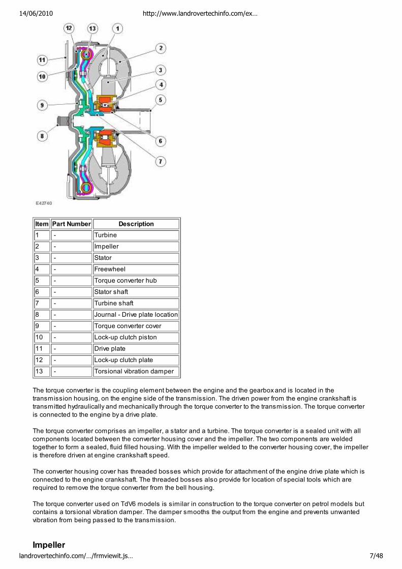
Item Part Number Description
1 - Turbine
2 - Impeller
3 - Stator
4 - Freewheel
5 - Torque converter hub
6 - Stator shaft
7 - Turbine shaft
8 - Journal - Drive plate location
9 - Torque converter cover
10 - Lock-up clutch piston
11 - Drive plate
12 - Lock-up clutch plate
13 - Torsional vibration damper
The torque converter is the coupling element between the engine and the gearbox and is located in the
transmission housing, on the engine side of the transmission. The driven power from the engine crankshaft is
transmitted hydraulically and mechanically through the torque converter to the transmission. The torque converter
is connected to the engine by a drive plate.
The torque converter comprises an impeller, a stator and a turbine. The torque converter is a sealed unit with all
components located between the converter housing cover and the impeller. The two components are welded
together to form a sealed, fluid filled housing. With the impeller welded to the converter housing cover, the impeller
is therefore driven at engine crankshaft speed.
The converter housing cover has threaded bosses which provide for attachment of the engine drive plate which is
connected to the engine crankshaft. The threaded bosses also provide for location of special tools which are
required to remove the torque converter from the bell housing.
The torque converter used on TdV6 models is similar in construction to the torque converter on petrol models but
contains a torsional vibration damper. The damper smooths the output from the engine and prevents unwanted
vibration from being passed to the transmission.
Impeller
14/06/2010 http://www.landrovertechinfo.com/ex…
landrovertechinfo.com/…/frmviewit.js… 7/48
Impeller
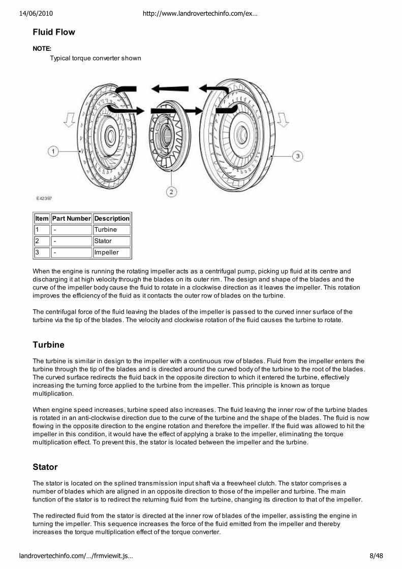
Fluid Flow
NOTE:
Typical torque converter shown
Item Part Number Description
1 - Turbine
2 - Stator
3 - Impeller
When the engine is running the rotating impeller acts as a centrifugal pump, picking up fluid at its centre and
discharging it at high velocity through the blades on its outer rim. The design and shape of the blades and the
curve of the impeller body cause the fluid to rotate in a clockwise direction as it leaves the impeller. This rotation
improves the efficiency of the fluid as it contacts the outer row of blades on the turbine.
The centrifugal force of the fluid leaving the blades of the impeller is passed to the curved inner surface of the
turbine via the tip of the blades. The velocity and clockwise rotation of the fluid causes the turbine to rotate.
Turbine
The turbine is similar in design to the impeller with a continuous row of blades. Fluid from the impeller enters the
turbine through the tip of the blades and is directed around the curved body of the turbine to the root of the blades.
The curved surface redirects the fluid back in the opposite direction to which it entered the turbine, effectively
increasing the turning force applied to the turbine from the impeller. This principle is known as torque
multiplication.
When engine speed increases, turbine speed also increases. The fluid leaving the inner row of the turbine blades
is rotated in an anti-clockwise direction due to the curve of the turbine and the shape of the blades. The fluid is now
flowing in the opposite direction to the engine rotation and therefore the impeller. If the fluid was allowed to hit the
impeller in this condition, it would have the effect of applying a brake to the impeller, eliminating the torque
multiplication effect. To prevent this, the stator is located between the impeller and the turbine.
Stator
The stator is located on the splined transmission input shaft via a freewheel clutch. The stator comprises a
number of blades which are aligned in an opposite direction to those of the impeller and turbine. The main
function of the stator is to redirect the returning fluid from the turbine, changing its direction to that of the impeller.
The redirected fluid from the stator is directed at the inner row of blades of the impeller, assisting the engine in
turning the impeller. This sequence increases the force of the fluid emitted from the impeller and thereby
increases the torque multiplication effect of the torque converter.
14/06/2010 http://www.landrovertechinfo.com/ex…
landrovertechinfo.com/…/frmviewit.js… 8/48
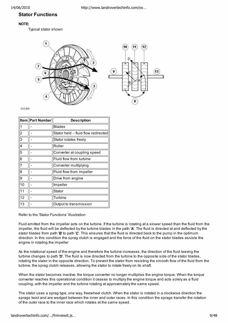
Stator Functions
NOTE:
Typical stator shown
Item Part Number Description
1 - Blades
2 - Stator held – fluid flow redirected
3 - Stator rotates freely
4 - Roller
5 - Converter at coupling speed
6 - Fluid flow from turbine
7 - Converter multiplying
8 - Fluid flow from impeller
9 - Drive from engine
10 - Impeller
11 - Stator
12 - Turbine
13 - Output to transmission
Refer to the 'Stator Functions' illustration
Fluid emitted from the impeller acts on the turbine. If the turbine is rotating at a slower speed than the fluid from the
impeller, the fluid will be deflected by the turbine blades in the path 'A'. The fluid is directed at and deflected by the
stator blades from path 'B' to path 'C'. This ensures that the fluid is directed back to the pump in the optimum
direction. In this condition the sprag clutch is engaged and the force of the fluid on the stator blades assists the
engine in rotating the impeller
As the rotational speed of the engine and therefore the turbine increases, the direction of the fluid leaving the
turbine changes to path 'D'. The fluid is now directed from the turbine to the opposite side of the stator blades,
rotating the stator in the opposite direction. To prevent the stator from resisting the smooth flow of the fluid from the
turbine, the sprag clutch releases, allowing the stator to rotate freely on its shaft.
When the stator becomes inactive, the torque converter no longer multiplies the engine torque. When the torque
converter reaches this operational condition it ceases to multiply the engine torque and acts solely as a fluid
coupling, with the impeller and the turbine rotating at approximately the same speed.
The stator uses a sprag type, one way, freewheel clutch. When the stator is rotated in a clockwise direction the
sprags twist and are wedged between the inner and outer races. In this condition the sprags transfer the rotation
of the outer race to the inner race which rotates at the same speed.
14/06/2010 http://www.landrovertechinfo.com/ex…
landrovertechinfo.com/…/frmviewit.js… 9/48
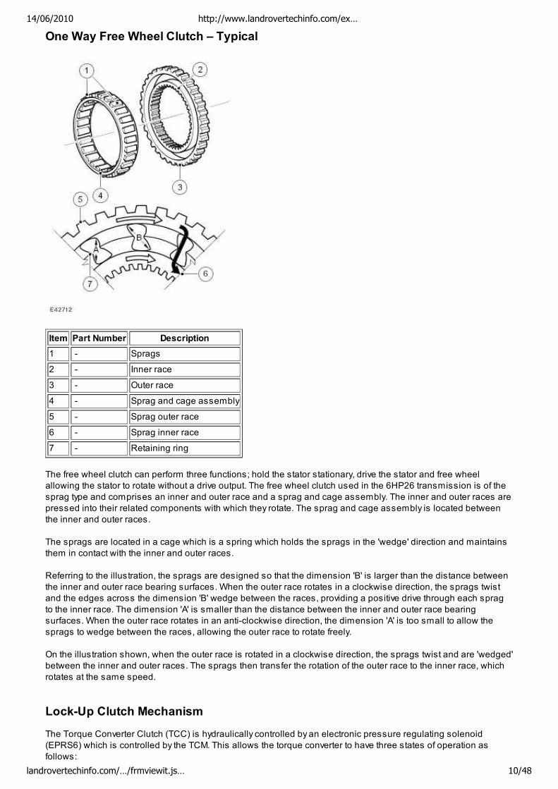
One Way Free Wheel Clutch – Typical
Item Part Number Description
1 - Sprags
2 - Inner race
3 - Outer race
4 - Sprag and cage assembly
5 - Sprag outer race
6 - Sprag inner race
7 - Retaining ring
The free wheel clutch can perform three functions; hold the stator stationary, drive the stator and free wheel
allowing the stator to rotate without a drive output. The free wheel clutch used in the 6HP26 transmission is of the
sprag type and comprises an inner and outer race and a sprag and cage assembly. The inner and outer races are
pressed into their related components with which they rotate. The sprag and cage assembly is located between
the inner and outer races.
The sprags are located in a cage which is a spring which holds the sprags in the 'wedge' direction and maintains
them in contact with the inner and outer races.
Referring to the illustration, the sprags are designed so that the dimension 'B' is larger than the distance between
the inner and outer race bearing surfaces. When the outer race rotates in a clockwise direction, the sprags twist
and the edges across the dimension 'B' wedge between the races, providing a positive drive through each sprag
to the inner race. The dimension 'A' is smaller than the distance between the inner and outer race bearing
surfaces. When the outer race rotates in an anti-clockwise direction, the dimension 'A' is too small to allow the
sprags to wedge between the races, allowing the outer race to rotate freely.
On the illustration shown, when the outer race is rotated in a clockwise direction, the sprags twist and are 'wedged'
between the inner and outer races. The sprags then transfer the rotation of the outer race to the inner race, which
rotates at the same speed.
Lock-Up Clutch Mechanism
The Torque Converter Clutch (TCC) is hydraulically controlled by an electronic pressure regulating solenoid
(EPRS6) which is controlled by the TCM. This allows the torque converter to have three states of operation as
follows:
14/06/2010 http://www.landrovertechinfo.com/ex…
landrovertechinfo.com/…/frmviewit.js… 10/48
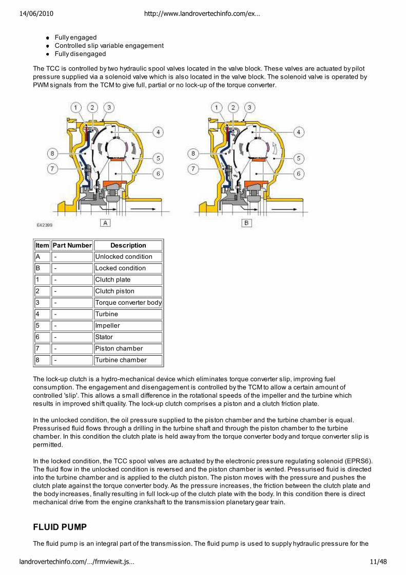
Fully engaged
Controlled slip variable engagement
Fully disengaged
The TCC is controlled by two hydraulic spool valves located in the valve block. These valves are actuated by pilot
pressure supplied via a solenoid valve which is also located in the valve block. The solenoid valve is operated by
PWM signals from the TCM to give full, partial or no lock-up of the torque converter.
Item Part Number Description
A - Unlocked condition
B - Locked condition
1 - Clutch plate
2 - Clutch piston
3 - Torque converter body
4 - Turbine
5 - Impeller
6 - Stator
7 - Piston chamber
8 - Turbine chamber
The lock-up clutch is a hydro-mechanical device which eliminates torque converter slip, improving fuel
consumption. The engagement and disengagement is controlled by the TCM to allow a certain amount of
controlled 'slip'. This allows a small difference in the rotational speeds of the impeller and the turbine which
results in improved shift quality. The lock-up clutch comprises a piston and a clutch friction plate.
In the unlocked condition, the oil pressure supplied to the piston chamber and the turbine chamber is equal.
Pressurised fluid flows through a drilling in the turbine shaft and through the piston chamber to the turbine
chamber. In this condition the clutch plate is held away from the torque converter body and torque converter slip is
permitted.
In the locked condition, the TCC spool valves are actuated by the electronic pressure regulating solenoid (EPRS6).
The fluid flow in the unlocked condition is reversed and the piston chamber is vented. Pressurised fluid is directed
into the turbine chamber and is applied to the clutch piston. The piston moves with the pressure and pushes the
clutch plate against the torque converter body. As the pressure increases, the friction between the clutch plate and
the body increases, finally resulting in full lock-up of the clutch plate with the body. In this condition there is direct
mechanical drive from the engine crankshaft to the transmission planetary gear train.
FLUID PUMP
The fluid pump is an integral part of the transmission. The fluid pump is used to supply hydraulic pressure for the
14/06/2010 http://www.landrovertechinfo.com/ex…
landrovertechinfo.com/…/frmviewit.js… 11/48
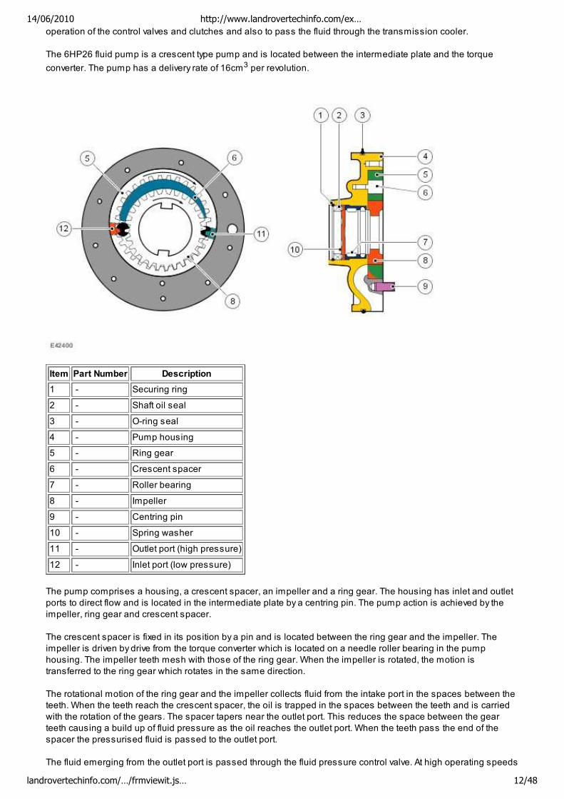
operation of the control valves and clutches and also to pass the fluid through the transmission cooler.
The 6HP26 fluid pump is a crescent type pump and is located between the intermediate plate and the torque
converter. The pump has a delivery rate of 16cm3 per revolution.
Item Part Number Description
1 - Securing ring
2 - Shaft oil seal
3 - O-ring seal
4 - Pump housing
5 - Ring gear
6 - Crescent spacer
7 - Roller bearing
8 - Impeller
9 - Centring pin
10 - Spring washer
11 - Outlet port (high pressure)
12 - Inlet port (low pressure)
The pump comprises a housing, a crescent spacer, an impeller and a ring gear. The housing has inlet and outlet
ports to direct flow and is located in the intermediate plate by a centring pin. The pump action is achieved by the
impeller, ring gear and crescent spacer.
The crescent spacer is fixed in its position by a pin and is located between the ring gear and the impeller. The
impeller is driven by drive from the torque converter which is located on a needle roller bearing in the pump
housing. The impeller teeth mesh with those of the ring gear. When the impeller is rotated, the motion is
transferred to the ring gear which rotates in the same direction.
The rotational motion of the ring gear and the impeller collects fluid from the intake port in the spaces between the
teeth. When the teeth reach the crescent spacer, the oil is trapped in the spaces between the teeth and is carried
with the rotation of the gears. The spacer tapers near the outlet port. This reduces the space between the gear
teeth causing a build up of fluid pressure as the oil reaches the outlet port. When the teeth pass the end of the
spacer the pressurised fluid is passed to the outlet port.
The fluid emerging from the outlet port is passed through the fluid pressure control valve. At high operating speeds
14/06/2010 http://www.landrovertechinfo.com/ex…
landrovertechinfo.com/…/frmviewit.js… 12/48
the pressure control valve maintains the output pressure to the gearbox at a predetermined maximum level.
Excess fluid is relieved from the pressure control valve and is directed, via the main pressure valve in the valve
block, back to the pump inlet port. This provides a pressurised feed to the pump inlet which prevents cavitation and
reduces pump noise.
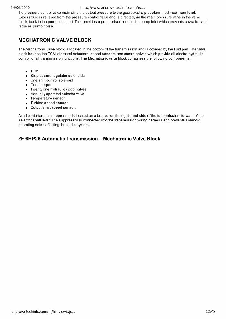
MECHATRONIC VALVE BLOCK
The Mechatronic valve block is located in the bottom of the transmission and is covered by the fluid pan. The valve
block houses the TCM, electrical actuators, speed sensors and control valves which provide all electro-hydraulic
control for all transmission functions. The Mechatronic valve block comprises the following components:
TCM
Six pressure regulator solenoids
One shift control solenoid
One damper
Twenty one hydraulic spool valves
Manually operated selector valve
Temperature sensor
Turbine speed sensor
Output shaft speed sensor.
A radio interference suppressor is located on a bracket on the right hand side of the transmission, forward of the
selector shaft lever. The suppressor is connected into the transmission wiring harness and prevents solenoid
operating noise affecting the audio system.
ZF 6HP26 Automatic Transmission – Mechatronic Valve Block
14/06/2010 http://www.landrovertechinfo.com/ex…
landrovertechinfo.com/…/frmviewit.js… 13/48
Item Part Number Description
1 - Position switch
2 - Sliding block
3 - Selector spool valve
4 - Position switch assembly
5 - Electronic Pressure Regulator Solenoid (EPRS) 6
6 - Solenoid Valve 1
7 - EPRS 4
8 - EPRS 5
9 - EPRS 3
10 - EPRS 2
11 - EPRS 1
12 - Electrical connector
13 - Transmission Control Module (TCM)
14/06/2010 http://www.landrovertechinfo.com/ex…
landrovertechinfo.com/…/frmviewit.js… 14/48
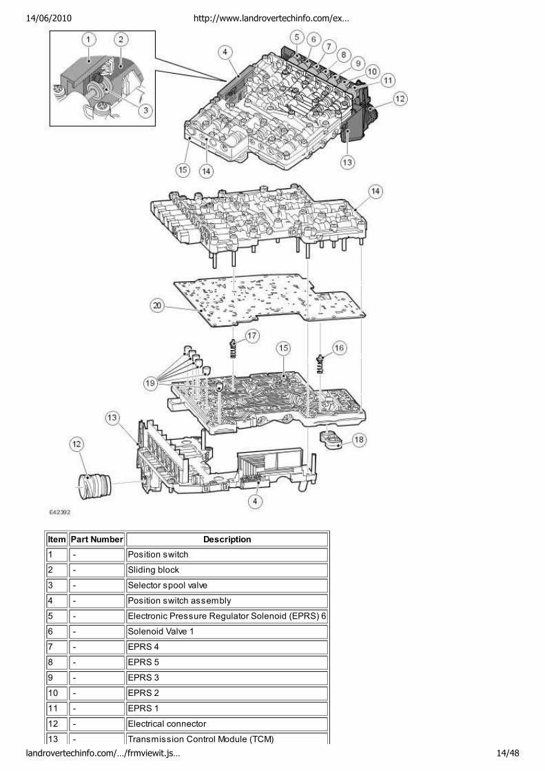
14 - Valve housing
15 - Valve plate
16 - Torque converter retaining valve
17 - Clutch return valve
18 - Element seal
19 - Pressure regulator dampers
20 - Intermediate plate
ZF 6HP26 Automatic Transmission – Valve Housing Components
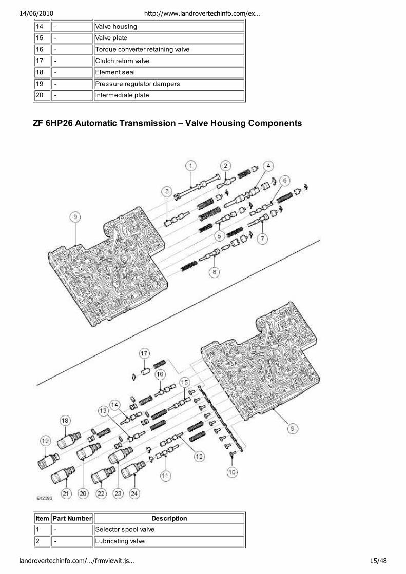
Item Part Number Description
1 - Selector spool valve
2 - Lubricating valve
14/06/2010 http://www.landrovertechinfo.com/ex…
landrovertechinfo.com/…/frmviewit.js… 15/48
3 - Torque converter pressure valve
4 - System pressure valve
5 - Torque converter clutch valve
6 - Retaining valve – Clutch E
7 - Clutch valve E
8 - Clutch valve A
9 - Valve housing
10 - Bolts
11 - Retaining valve – Clutch A
12 - Retaining valve – Clutch B
13 - Pressure reducing valve
14 - Shift valve 1
15 - Retaining valve – Brake D
16 - Shift valve 2
17 - Damper
18 - Electronic Pressure Regulator Solenoid (EPRS) 6
19 - Solenoid valve 1
20 - EPRS 4
21 - EPRS 5
22 - EPRS 2
23 - EPRS 3
24 - EPRS 1
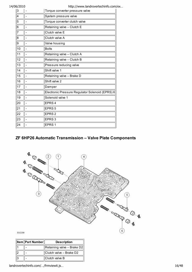
ZF 6HP26 Automatic Transmission – Valve Plate Components
Item Part Number Description
1 - Retaining valve – Brake D2
2 - Clutch valve – Brake D2
3 - Clutch valve B
14/06/2010 http://www.landrovertechinfo.com/ex…
landrovertechinfo.com/…/frmviewit.js… 16/48
4 - Valve plate
5 - Clutch valve – Brake D1
6 - Clutch valve – Brake C
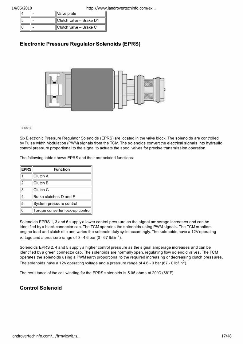
Electronic Pressure Regulator Solenoids (EPRS)
Six Electronic Pressure Regulator Solenoids (EPRS) are located in the valve block. The solenoids are controlled
by Pulse width Modulation (PWM) signals from the TCM. The solenoids convert the electrical signals into hydraulic
control pressure proportional to the signal to actuate the spool valves for precise transmission operation.
The following table shows EPRS and their associated functions:
EPRS Function
1 Clutch A
2 Clutch B
3 Clutch C
4 Brake clutches D and E
5 System pressure control
6 Torque converter lock-up control
Solenoids EPRS 1, 3 and 6 supply a lower control pressure as the signal amperage increases and can be
identified by a black connector cap. The TCM operates the solenoids using PWM signals. The TCM monitors
engine load and clutch slip and varies the solenoid duty cycle accordingly. The solenoids have a 12V operating
voltage and a pressure range of 0 - 4.6 bar (0 - 67 lbf.in2).
Solenoids EPRS 2, 4 and 5 supply a higher control pressure as the signal amperage increases and can be
identified by a green connector cap. The solenoids are normally open, regulating flow solenoid valves. The TCM
operates the solenoids using a PWM earth proportional to the required increasing or decreasing clutch pressures.
The solenoids have a 12V operating voltage and a pressure range of 4.6 - 0 bar (67 - 0 lbf.in2).
The resistance of the coil winding for the EPRS solenoids is 5.05 ohms at 20°C (68°F).
Control Solenoid
14/06/2010 http://www.landrovertechinfo.com/ex…
landrovertechinfo.com/…/frmviewit.js… 17/48
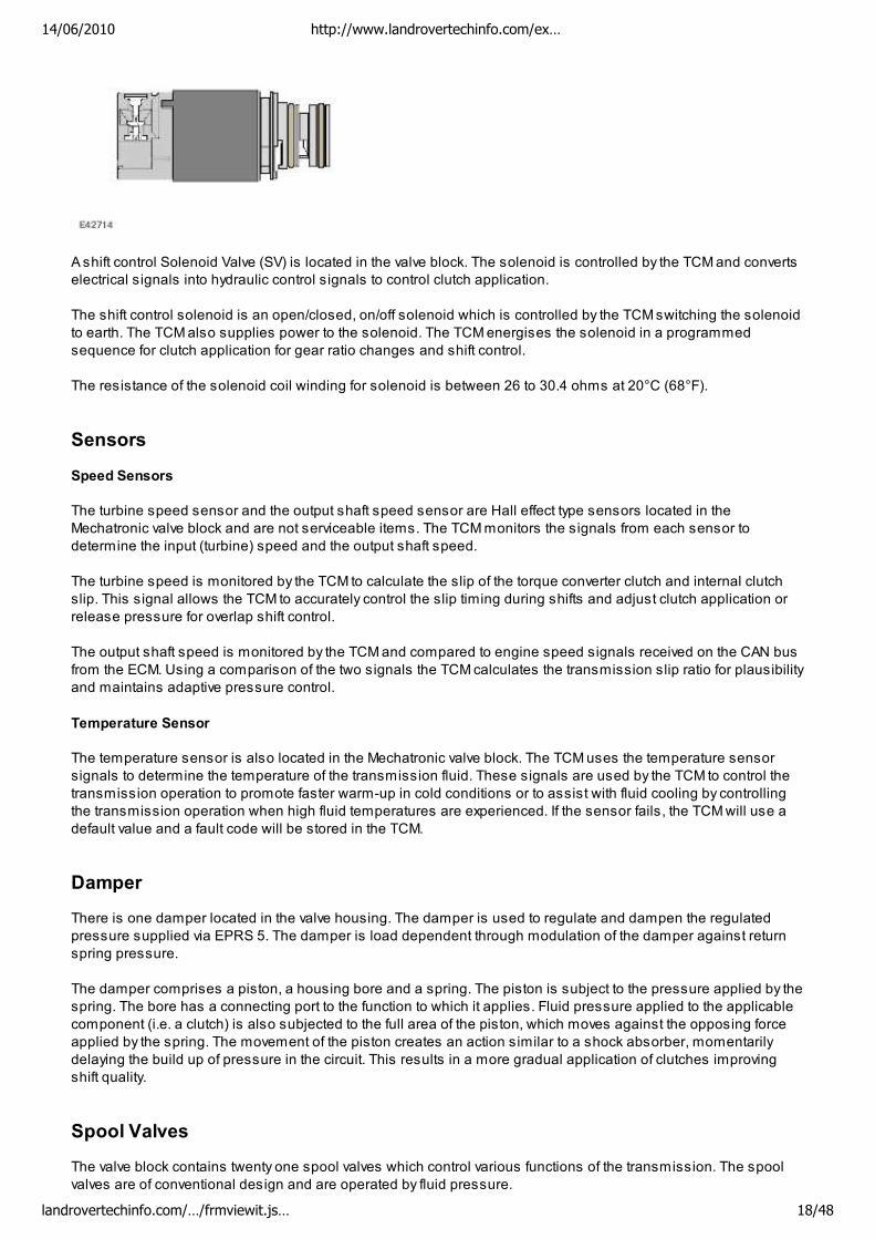
A shift control Solenoid Valve (SV) is located in the valve block. The solenoid is controlled by the TCM and converts
electrical signals into hydraulic control signals to control clutch application.
The shift control solenoid is an open/closed, on/off solenoid which is controlled by the TCM switching the solenoid
to earth. The TCM also supplies power to the solenoid. The TCM energises the solenoid in a programmed
sequence for clutch application for gear ratio changes and shift control.
The resistance of the solenoid coil winding for solenoid is between 26 to 30.4 ohms at 20°C (68°F).
Sensors
Speed Sensors
The turbine speed sensor and the output shaft speed sensor are Hall effect type sensors located in the
Mechatronic valve block and are not serviceable items. The TCM monitors the signals from each sensor to
determine the input (turbine) speed and the output shaft speed.
The turbine speed is monitored by the TCM to calculate the slip of the torque converter clutch and internal clutch
slip. This signal allows the TCM to accurately control the slip timing during shifts and adjust clutch application or
release pressure for overlap shift control.
The output shaft speed is monitored by the TCM and compared to engine speed signals received on the CAN bus
from the ECM. Using a comparison of the two signals the TCM calculates the transmission slip ratio for plausibility
and maintains adaptive pressure control.
Temperature Sensor
The temperature sensor is also located in the Mechatronic valve block. The TCM uses the temperature sensor
signals to determine the temperature of the transmission fluid. These signals are used by the TCM to control the
transmission operation to promote faster warm-up in cold conditions or to assist with fluid cooling by controlling
the transmission operation when high fluid temperatures are experienced. If the sensor fails, the TCM will use a
default value and a fault code will be stored in the TCM.
Damper
There is one damper located in the valve housing. The damper is used to regulate and dampen the regulated
pressure supplied via EPRS 5. The damper is load dependent through modulation of the damper against return
spring pressure.
The damper comprises a piston, a housing bore and a spring. The piston is subject to the pressure applied by the
spring. The bore has a connecting port to the function to which it applies. Fluid pressure applied to the applicable
component (i.e. a clutch) is also subjected to the full area of the piston, which moves against the opposing force
applied by the spring. The movement of the piston creates an action similar to a shock absorber, momentarily
delaying the build up of pressure in the circuit. This results in a more gradual application of clutches improving
shift quality.
Spool Valves
The valve block contains twenty one spool valves which control various functions of the transmission. The spool
valves are of conventional design and are operated by fluid pressure.
14/06/2010 http://www.landrovertechinfo.com/ex…
landrovertechinfo.com/…/frmviewit.js… 18/48
Each spool valve is located in its spool bore and held in a default (unpressurised) position by a spring. The spool
bore has a number of ports which allow fluid to flow to other valves and clutches to enable transmission operation.
Each spool has a piston which is waisted to allow fluid to be diverted into the applicable ports when the valve is
operated.
When fluid pressure moves a spool, one or more ports in the spool bore are covered or uncovered. Fluid is
prevented from flowing or is allowed to flow around the applicable waisted area of the spool and into another
uncovered port. The fluid is either passed through galleries to actuate another spool, operate a clutch or is
returned to the fluid pan.
DRIVE CLUTCHES
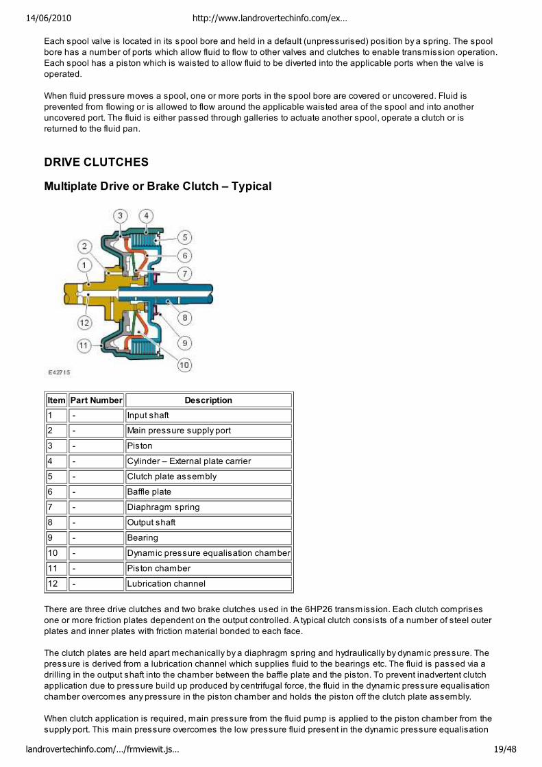
Multiplate Drive or Brake Clutch – Typical
Item Part Number Description
1 - Input shaft
2 - Main pressure supply port
3 - Piston
4 - Cylinder – External plate carrier
5 - Clutch plate assembly
6 - Baffle plate
7 - Diaphragm spring
8 - Output shaft
9 - Bearing
10 - Dynamic pressure equalisation chamber
11 - Piston chamber
12 - Lubrication channel
There are three drive clutches and two brake clutches used in the 6HP26 transmission. Each clutch comprises
one or more friction plates dependent on the output controlled. A typical clutch consists of a number of steel outer
plates and inner plates with friction material bonded to each face.
The clutch plates are held apart mechanically by a diaphragm spring and hydraulically by dynamic pressure. The
pressure is derived from a lubrication channel which supplies fluid to the bearings etc. The fluid is passed via a
drilling in the output shaft into the chamber between the baffle plate and the piston. To prevent inadvertent clutch
application due to pressure build up produced by centrifugal force, the fluid in the dynamic pressure equalisation
chamber overcomes any pressure in the piston chamber and holds the piston off the clutch plate assembly.
When clutch application is required, main pressure from the fluid pump is applied to the piston chamber from the
supply port. This main pressure overcomes the low pressure fluid present in the dynamic pressure equalisation
14/06/2010 http://www.landrovertechinfo.com/ex…
landrovertechinfo.com/…/frmviewit.js… 19/48
chamber. The piston moves, against the pressure applied by the diaphragm spring, and compresses the clutch
plate assembly. When the main pressure falls, the diaphragm spring pushes the piston away from the clutch plate
assembly, disengaging the clutch.
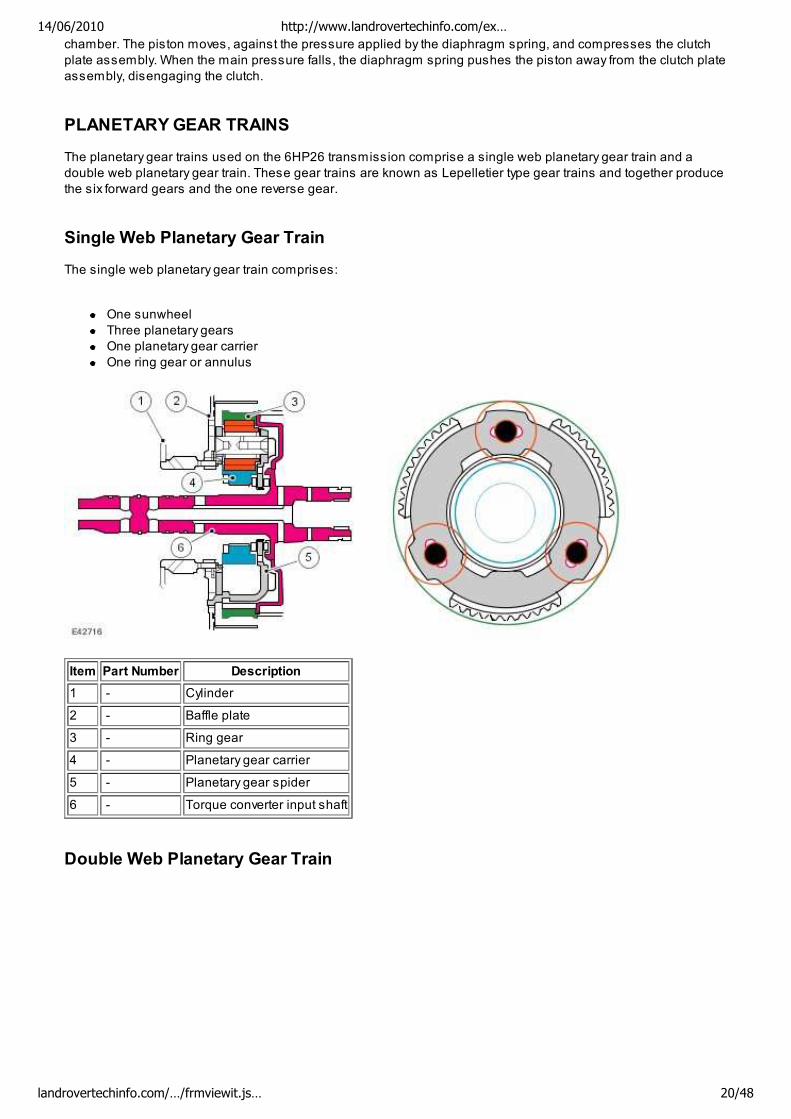
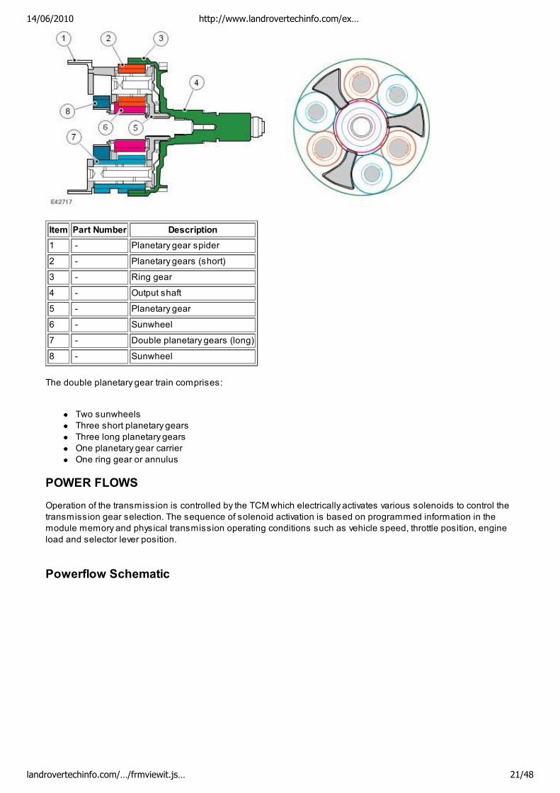
PLANETARY GEAR TRAINS
The planetary gear trains used on the 6HP26 transmission comprise a single web planetary gear train and a
double web planetary gear train. These gear trains are known as Lepelletier type gear trains and together produce
the six forward gears and the one reverse gear.
Single Web Planetary Gear Train
The single web planetary gear train comprises:
One sunwheel
Three planetary gears
One planetary gear carrier
One ring gear or annulus
Item Part Number Description
1 - Cylinder
2 - Baffle plate
3 - Ring gear
4 - Planetary gear carrier
5 - Planetary gear spider
6 - Torque converter input shaft
Double Web Planetary Gear Train
14/06/2010 http://www.landrovertechinfo.com/ex…
landrovertechinfo.com/…/frmviewit.js… 20/48
Item Part Number Description
1 - Planetary gear spider
2 - Planetary gears (short)
3 - Ring gear
4 - Output shaft
5 - Planetary gear
6 - Sunwheel
7 - Double planetary gears (long)
8 - Sunwheel
The double planetary gear train comprises:
Two sunwheels
Three short planetary gears
Three long planetary gears
One planetary gear carrier
One ring gear or annulus
POWER FLOWS
Operation of the transmission is controlled by the TCM which electrically activates various solenoids to control the
transmission gear selection. The sequence of solenoid activation is based on programmed information in the
module memory and physical transmission operating conditions such as vehicle speed, throttle position, engine
load and selector lever position.
Powerflow Schematic
14/06/2010 http://www.landrovertechinfo.com/ex…
landrovertechinfo.com/…/frmviewit.js… 21/48
Item Part Number Description
1 - Torque input from engine
2 - Torque converter lock-up clutch
3 - Single web planetary gear carrier
4 - Single web planetary gears
5 - Single web sunwheel 1
6 - Double web sunwheel 2
7 - Double web planetary gears - Long
8 - Double web planetary gear carrier
9 - Double web planetary gears - Short
10 - Double web sunwheel 3
11 - Torque output from transmission
A - Multiplate clutch
B - Multiplate clutch
C - Multiplate brake
D - Multiplate brake
E - Multiplate clutch
Engine torque is transferred, via operation of single or combinations of clutches to the two planetary gear trains.
Both gear trains are controlled by reactionary inputs from brake clutches to produce the six forward gears and one
reverse gear. The ratios are as follows:
Gear 1st 2nd 3rd 4th 5th 6th Reverse
Ratio 4.171 2.340 1.521 1.143 0.867 0.691 3.403
The following table shows which solenoids are activated to produce the required torque output from the
transmission.
Gear Selector Lever PositionShift Control
Solenoid Valve
Electronic Pressure
Regulator Solenoids
(EPRS)
1 2 3 4 5 6
P ON -
ON-
R ON ON -
ON-
N ON -
ON-
D 1 ON ON - -
14/06/2010 http://www.landrovertechinfo.com/ex…
landrovertechinfo.com/…/frmviewit.js… 22/48
ON- ON-
D 2 ON ON -
ON-
-
ON-
D 3 ON ON -
ON-
-
ON-
D 4 ON ON ON -
ON-
-
ON-
D 5 ON ON ON -
ON-
-
ON-
D 6 ON ON ON -
ON-
-
ON-
ON = Active (pressure build up) OFF =
Inactive -ON- = Inactive (pressure drain)
The following table shows which clutches are operating for selected gear ratios to produce the required torque
output from the transmission.
Gear Selector Lever Position Shift Control Solenoid Valve Clutch Brake A B E WK C D
P X
R X X
N X
D 1 X X X
D 2 X X X
D 3 X X X
D 4 ON X X X
D 5 ON X X X
D 6 ON X X X
X = clutch applied
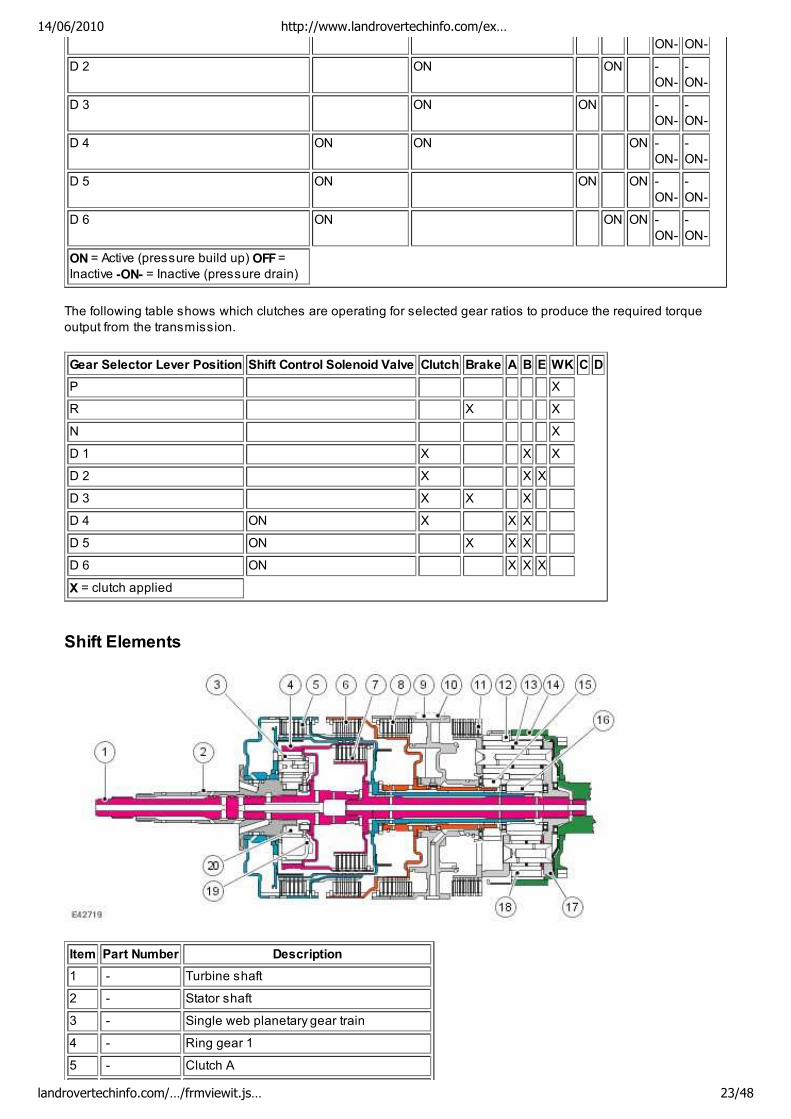
Shift Elements
Item Part Number Description
1 - Turbine shaft
2 - Stator shaft
3 - Single web planetary gear train
4 - Ring gear 1
5 - Clutch A
14/06/2010 http://www.landrovertechinfo.com/ex…
landrovertechinfo.com/…/frmviewit.js… 23/48
6 - Clutch B
7 - Clutch E
8 - Brake clutch C
9 - Fixed connection to transmission housing
10 - Shaft key
11 - Brake clutch D
12 - Double web planetary gear train
13 - Planetary gears - Long
14 - Ring gear 2
15 - Sunwheel 2
16 - Sunwheel 3
17 - Double web planetary gear carrier
18 - Planetary gears - short
19 - Single web planetary gear carrier
20 - Sunwheel 1
The shift elements are three rotating multiplate clutches (A, B and E) and two fixed multiplate brakes © and D). All
shifts from 1st to 6th gears are power-on overlapping shifts. Overlapping shifts can be described as one of the
clutches continuing to transmit drive at a lower main pressure until the next required clutch is able to accept the
input torque.
The shift elements, clutches and brakes are actuated hydraulically. Fluid pressure is applied to the required clutch
and/or brake, pressing the plates together and allowing drive to be transmitted through the plates. The purpose of
the shift elements is to perform power-on shifts with no interruption to traction and smooth transition between gear
ratios.
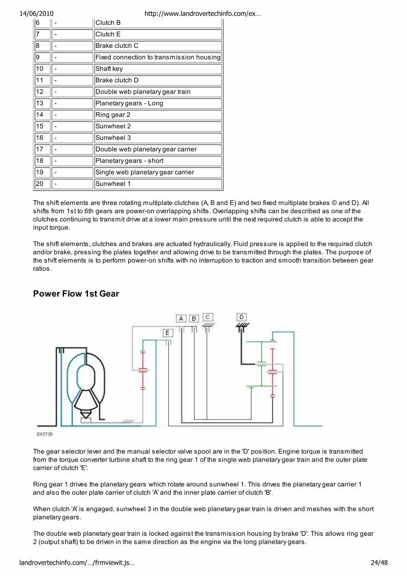
Power Flow 1st Gear
The gear selector lever and the manual selector valve spool are in the 'D' position. Engine torque is transmitted
from the torque converter turbine shaft to the ring gear 1 of the single web planetary gear train and the outer plate
carrier of clutch 'E'.
Ring gear 1 drives the planetary gears which rotate around sunwheel 1. This drives the planetary gear carrier 1
and also the outer plate carrier of clutch 'A' and the inner plate carrier of clutch 'B'.
When clutch 'A' is engaged, sunwheel 3 in the double web planetary gear train is driven and meshes with the short
planetary gears.
The double web planetary gear train is locked against the transmission housing by brake 'D'. This allows ring gear
2 (output shaft) to be driven in the same direction as the engine via the long planetary gears.
14/06/2010 http://www.landrovertechinfo.com/ex…
landrovertechinfo.com/…/frmviewit.js… 24/48
NOTE:
Refer to 'Shift Elements' illustration for key
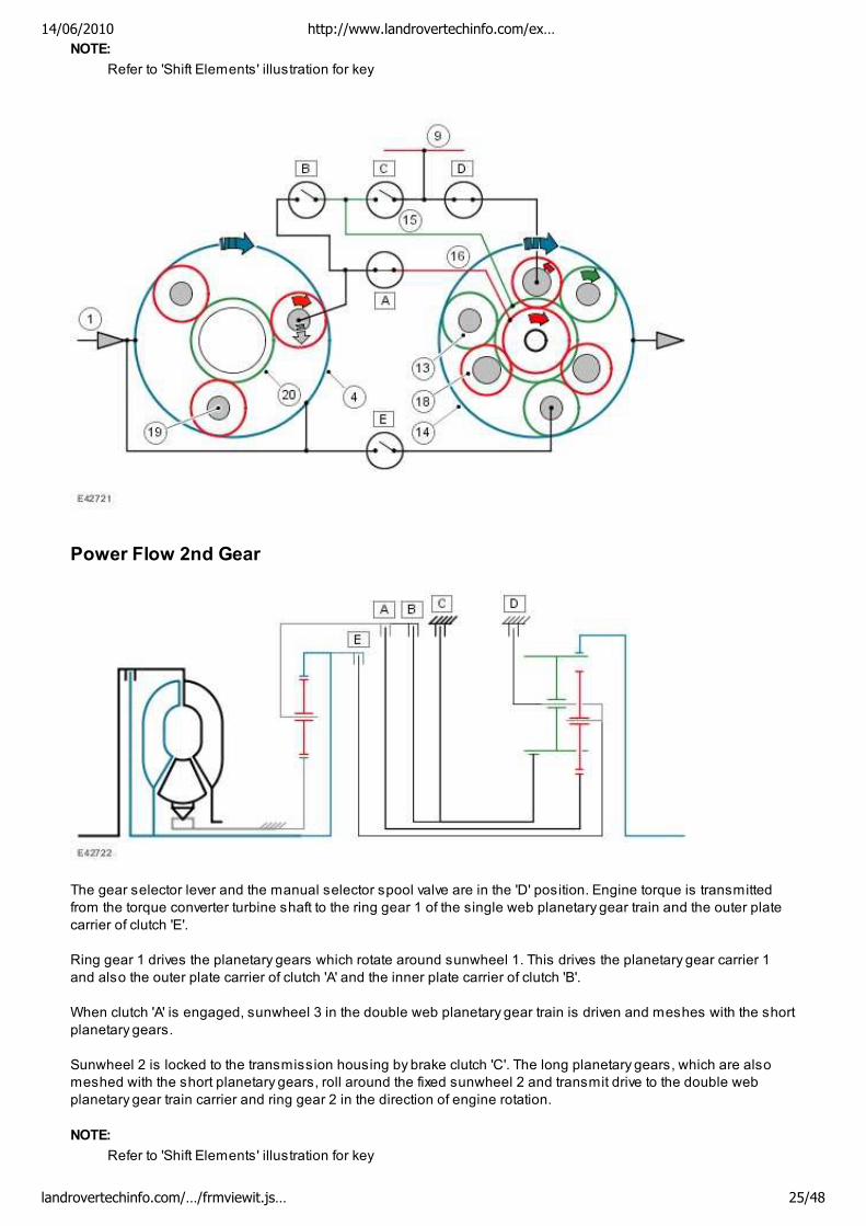
Power Flow 2nd Gear
The gear selector lever and the manual selector spool valve are in the 'D' position. Engine torque is transmitted
from the torque converter turbine shaft to the ring gear 1 of the single web planetary gear train and the outer plate
carrier of clutch 'E'.
Ring gear 1 drives the planetary gears which rotate around sunwheel 1. This drives the planetary gear carrier 1
and also the outer plate carrier of clutch 'A' and the inner plate carrier of clutch 'B'.
When clutch 'A' is engaged, sunwheel 3 in the double web planetary gear train is driven and meshes with the short
planetary gears.
Sunwheel 2 is locked to the transmission housing by brake clutch 'C'. The long planetary gears, which are also
meshed with the short planetary gears, roll around the fixed sunwheel 2 and transmit drive to the double web
planetary gear train carrier and ring gear 2 in the direction of engine rotation.
NOTE:
Refer to 'Shift Elements' illustration for key
14/06/2010 http://www.landrovertechinfo.com/ex…
landrovertechinfo.com/…/frmviewit.js… 25/48
Power Flow 3rd Gear
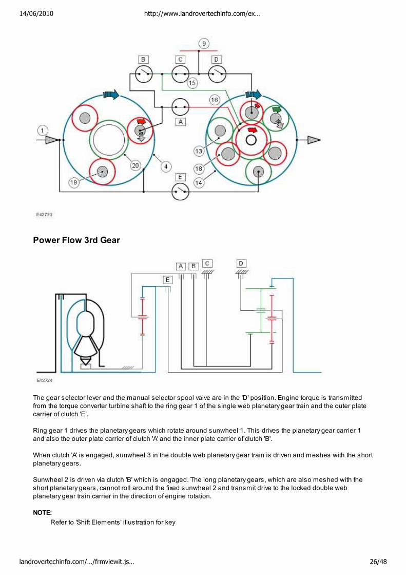
The gear selector lever and the manual selector spool valve are in the 'D' position. Engine torque is transmitted
from the torque converter turbine shaft to the ring gear 1 of the single web planetary gear train and the outer plate
carrier of clutch 'E'.
Ring gear 1 drives the planetary gears which rotate around sunwheel 1. This drives the planetary gear carrier 1
and also the outer plate carrier of clutch 'A' and the inner plate carrier of clutch 'B'.
When clutch 'A' is engaged, sunwheel 3 in the double web planetary gear train is driven and meshes with the short
planetary gears.
Sunwheel 2 is driven via clutch 'B' which is engaged. The long planetary gears, which are also meshed with the
short planetary gears, cannot roll around the fixed sunwheel 2 and transmit drive to the locked double web
planetary gear train carrier in the direction of engine rotation.
NOTE:
Refer to 'Shift Elements' illustration for key
14/06/2010 http://www.landrovertechinfo.com/ex…
landrovertechinfo.com/…/frmviewit.js… 26/48
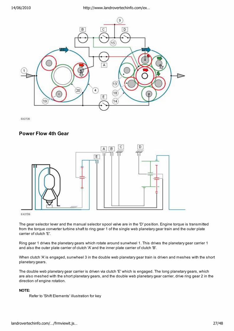
Power Flow 4th Gear
The gear selector lever and the manual selector spool valve are in the 'D' position. Engine torque is transmitted
from the torque converter turbine shaft to ring gear 1 of the single web planetary gear train and the outer plate
carrier of clutch 'E'.
Ring gear 1 drives the planetary gears which rotate around sunwheel 1. This drives the planetary gear carrier 1
and also the outer plate carrier of clutch 'A' and the inner plate carrier of clutch 'B'.
When clutch 'A' is engaged, sunwheel 3 in the double web planetary gear train is driven and meshes with the short
planetary gears.
The double web planetary gear carrier is driven via clutch 'E' which is engaged. The long planetary gears, which
are also meshed with the short planetary gears, and the double web planetary gear carrier, drive ring gear 2 in the
direction of engine rotation.
NOTE:
Refer to 'Shift Elements' illustration for key
14/06/2010 http://www.landrovertechinfo.com/ex…
landrovertechinfo.com/…/frmviewit.js… 27/48
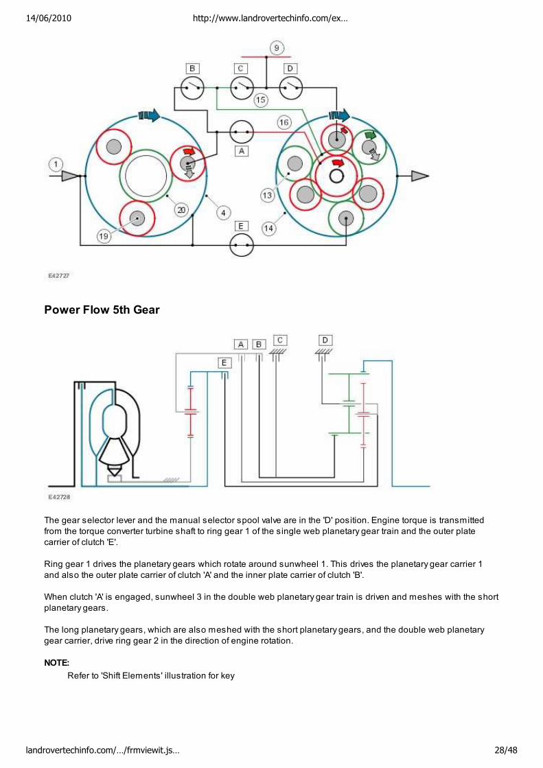
Power Flow 5th Gear
The gear selector lever and the manual selector spool valve are in the 'D' position. Engine torque is transmitted
from the torque converter turbine shaft to ring gear 1 of the single web planetary gear train and the outer plate
carrier of clutch 'E'.
Ring gear 1 drives the planetary gears which rotate around sunwheel 1. This drives the planetary gear carrier 1
and also the outer plate carrier of clutch 'A' and the inner plate carrier of clutch 'B'.
When clutch 'A' is engaged, sunwheel 3 in the double web planetary gear train is driven and meshes with the short
planetary gears.
The long planetary gears, which are also meshed with the short planetary gears, and the double web planetary
gear carrier, drive ring gear 2 in the direction of engine rotation.
NOTE:
Refer to 'Shift Elements' illustration for key
14/06/2010 http://www.landrovertechinfo.com/ex…
landrovertechinfo.com/…/frmviewit.js… 28/48
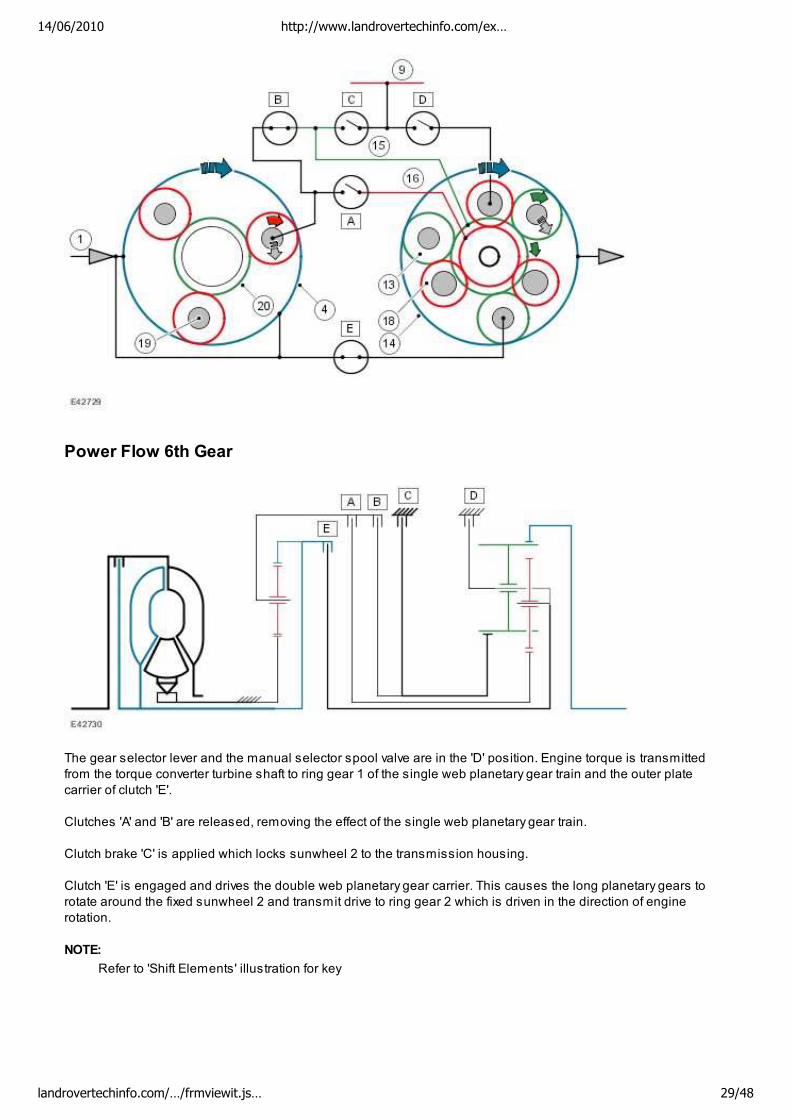
Power Flow 6th Gear
The gear selector lever and the manual selector spool valve are in the 'D' position. Engine torque is transmitted
from the torque converter turbine shaft to ring gear 1 of the single web planetary gear train and the outer plate
carrier of clutch 'E'.
Clutches 'A' and 'B' are released, removing the effect of the single web planetary gear train.
Clutch brake 'C' is applied which locks sunwheel 2 to the transmission housing.
Clutch 'E' is engaged and drives the double web planetary gear carrier. This causes the long planetary gears to
rotate around the fixed sunwheel 2 and transmit drive to ring gear 2 which is driven in the direction of engine
rotation.
NOTE:
Refer to 'Shift Elements' illustration for key
14/06/2010 http://www.landrovertechinfo.com/ex…
landrovertechinfo.com/…/frmviewit.js… 29/48
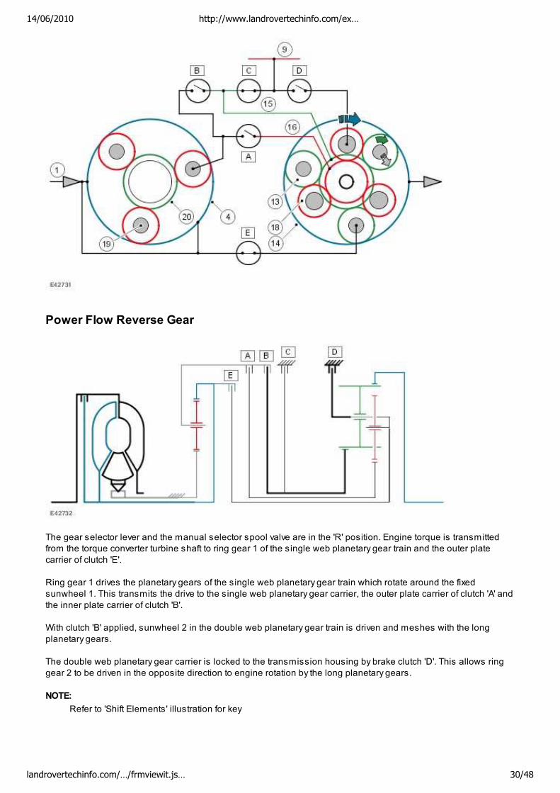
Power Flow Reverse Gear
The gear selector lever and the manual selector spool valve are in the 'R' position. Engine torque is transmitted
from the torque converter turbine shaft to ring gear 1 of the single web planetary gear train and the outer plate
carrier of clutch 'E'.
Ring gear 1 drives the planetary gears of the single web planetary gear train which rotate around the fixed
sunwheel 1. This transmits the drive to the single web planetary gear carrier, the outer plate carrier of clutch 'A' and
the inner plate carrier of clutch 'B'.
With clutch 'B' applied, sunwheel 2 in the double web planetary gear train is driven and meshes with the long
planetary gears.
The double web planetary gear carrier is locked to the transmission housing by brake clutch 'D'. This allows ring
gear 2 to be driven in the opposite direction to engine rotation by the long planetary gears.
NOTE:
Refer to 'Shift Elements' illustration for key
14/06/2010 http://www.landrovertechinfo.com/ex…
landrovertechinfo.com/…/frmviewit.js… 30/48
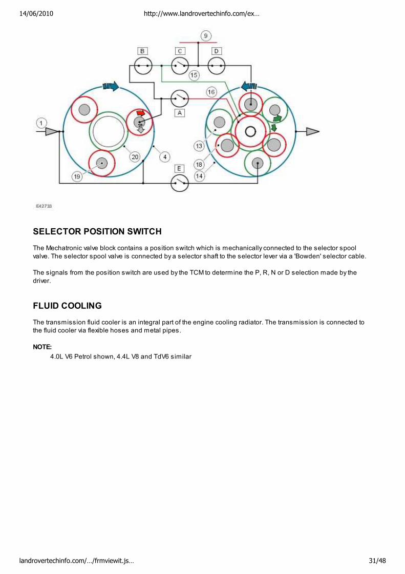
SELECTOR POSITION SWITCH
The Mechatronic valve block contains a position switch which is mechanically connected to the selector spool
valve. The selector spool valve is connected by a selector shaft to the selector lever via a 'Bowden' selector cable.
The signals from the position switch are used by the TCM to determine the P, R, N or D selection made by the
driver.
FLUID COOLING
The transmission fluid cooler is an integral part of the engine cooling radiator. The transmission is connected to
the fluid cooler via flexible hoses and metal pipes.
NOTE:
4.0L V6 Petrol shown, 4.4L V8 and TdV6 similar
14/06/2010 http://www.landrovertechinfo.com/ex…
landrovertechinfo.com/…/frmviewit.js… 31/48
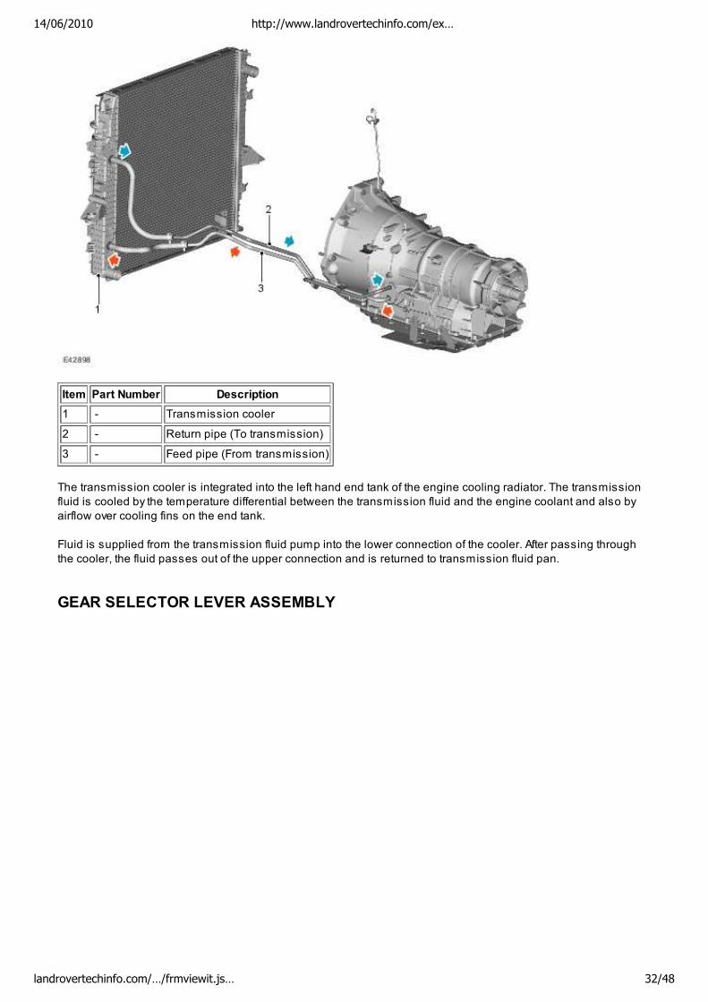
Item Part Number Description
1 - Transmission cooler
2 - Return pipe (To transmission)
3 - Feed pipe (From transmission)
The transmission cooler is integrated into the left hand end tank of the engine cooling radiator. The transmission
fluid is cooled by the temperature differential between the transmission fluid and the engine coolant and also by
airflow over cooling fins on the end tank.
Fluid is supplied from the transmission fluid pump into the lower connection of the cooler. After passing through
the cooler, the fluid passes out of the upper connection and is returned to transmission fluid pan.
GEAR SELECTOR LEVER ASSEMBLY
14/06/2010 http://www.landrovertechinfo.com/ex…
landrovertechinfo.com/…/frmviewit.js… 32/48
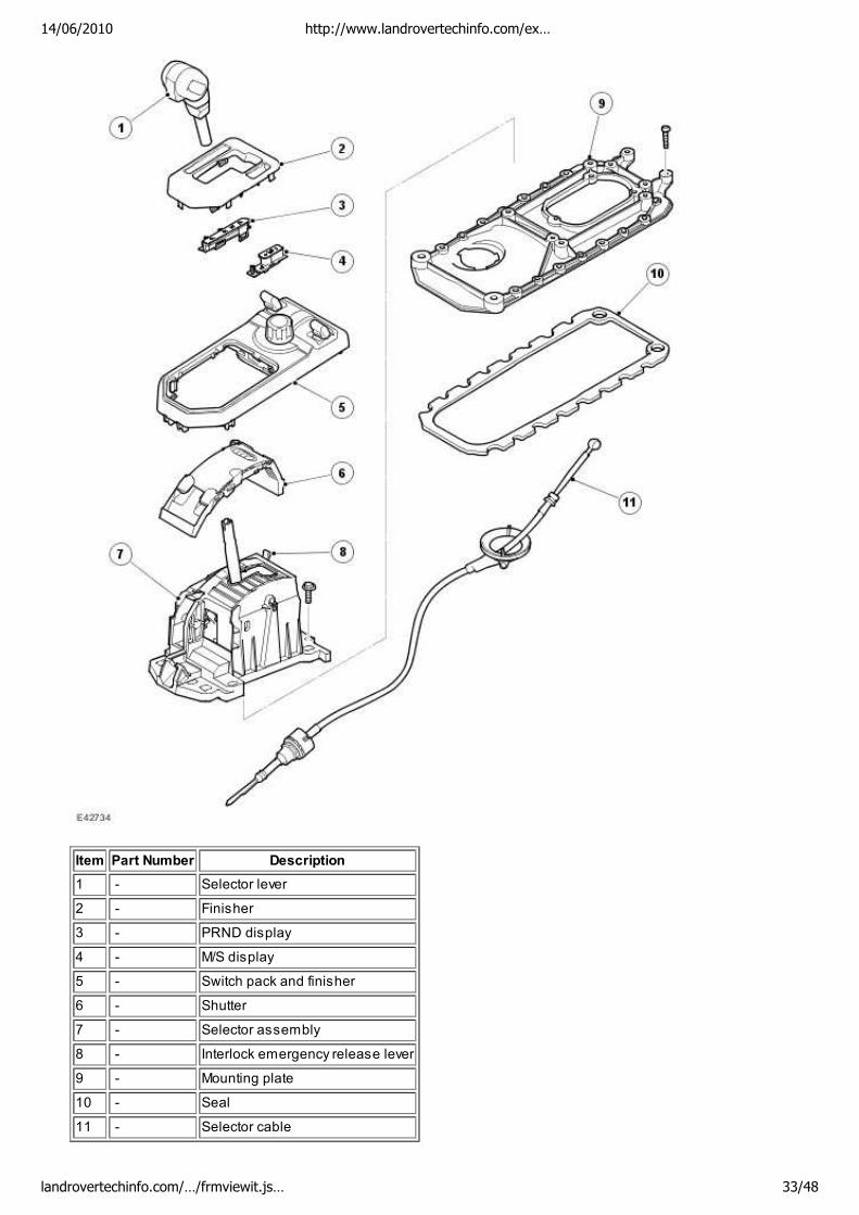
Item Part Number Description
1 - Selector lever
2 - Finisher
3 - PRND display
4 - M/S display
5 - Switch pack and finisher
6 - Shutter
7 - Selector assembly
8 - Interlock emergency release lever
9 - Mounting plate
10 - Seal
11 - Selector cable
14/06/2010 http://www.landrovertechinfo.com/ex…
landrovertechinfo.com/…/frmviewit.js… 33/48
The gear selector lever assembly is located in a central position on the transmission tunnel, between the front
driver and passenger seats and is secured to the transmission tunnel closure plate. The selector lever comprises
a moulded plastic housing which provides for the location of the selector components.
The lever is connected to a crosspiece which allows for the selection of P, R, N, D in a forward or backward
direction and selection between automatic and manual/sport mode in a left/right transverse direction.
When manual/sport mode is selected the lever can be moved in a forward or backward direction to select + or - for
manual (CommandShift™) operation. If left in Sport mode all gear changes are performed automatically.
If Manual (CommandShift™) mode is selected, all gear changes are based on inputs received by the TCM from
the manual +/- hall effect sensors located on the PCB.
The selector lever mechanism houses the following components:
Electronic Printed Circuit Board (PCB)
Shift Interlock solenoid
Park and Neutral locking levers.
There are four selector lever positions and two additional positions for manual/sport operation:
P (Park) - Prevents the vehicle from moving by locking the transmission
R (Reverse) - Select only when the vehicle is stationary and the engine is at idle
N (Neutral) - No torque transmitted to drive wheels
D (Drive) - This position uses all six forward gears in high and low ranges
M/S (Sport Mode) - This position uses all forward gears in 'D' but will upshift at higher engine speeds to
improve acceleration
+ and - (Manual 'CommandShift™' mode) - Movement of the selector lever in the +/- positions, when the
lever is in the M/S position, will operate the transmission in manual (CommandShift™) mode allowing the
driver to manually select all six forward gears
The selector lever position is displayed to the driver on the selector position LED display and in the instrument
cluster. In 'CommandShift™' mode, if a gear is selected but the TCM logic prevents selection of that gear, the
requested gear will be initially displayed. The TCM will engage the next allowed gear and then display that gear.
Sport/Manual +/- CommandShift™ Switch
The PCB contains the hall effect sensors to activate the sport/manual mode and also the sensors which provide
the +/- signals. When the selector lever is moved to the manual/sport position, the lower magnet located in the
selector lever is moved within proximity of the M/S hall effect sensor on the PCB. This provides the momentary
signal which is received by the TCM, which in turn initiates sport mode.
When the lever is moved to the + or - position, the magnet is moved within proximity of one of the hall effect
sensors positioned either side of the M/S hall effect sensor. When an input from either the + or - sensors is
received, manual CommandShift™ mode will be initiated. In this position a spring will move the selector lever
back to the centre position when released. To leave the CommandShift™ mode, return the lever to the 'D' position.
Selector Position LED Display
The P, R, N, D LED display is located on the right hand side of the selector lever and the M/S (MANUAL/SPORT) +/-
LED display is located on the left hand side of the selector lever. Each LED display is connected via a separate
harness to the selector lever position switch. When the lever is moved to the required position, the switch contact
for that position is made and the LED is illuminated.
P, R, N, D Position Switch
The P, R, N, D position switch is located within the Mechatronic valve block in the transmission. The switch is
operated by movement of the selector lever to the P, R, N or D positions via the Bowden cable which is connected
between the selector lever and the transmission selector shaft.
The switch is electrically connected to the TCM which outputs a common power supply to each of the four switch
14/06/2010 http://www.landrovertechinfo.com/ex…
landrovertechinfo.com/…/frmviewit.js… 34/48
contacts. This power supply is also used by the two speed sensors and the fluid temperature sensor. Each of the
four switch contacts have a separate feed input to the TCM which can detect which selector lever position has
been selected.
Shift Interlock Solenoid
The shift interlock solenoid is located on the side of the selector lever assembly. The solenoid operates two
locking levers which engage in the lower lever and lock it in the Park (P) and Neutral (N) positions. When the
ignition is on or the engine is running, the solenoid is de-energised and prevents the lever from moving.
When energised, by the depression of the footbrake, the solenoid is energised and the selector lever may be
moved from the P position. If the selector lever is left in the N position for more than 800m/s the solenoid will be
energised and the selector lever will become locked in the N position. To move the selector lever from the N
position in this condition the footbrake must be applied. This prevents the selector lever from being moved to the
'D' or 'R' position unintentionally and the application of the brakes also prevents the vehicle 'creeping' when the
gear is engaged.
Movement of the selector lever from the 'P' or 'N' positions is also prevented if the TCM senses the engine speed is
above 2500 rev/min, even if the brake pedal is depressed.
In the event of an electrical failure of the vehicle or failure of the interlock solenoid or its associated wiring, it is
possible to move the selector lever from the Park 'P' position by removing the coin tray on left hand drive vehicles or
the trim panel behind the park brake switch on right hand drive vehicles and lifting the white coloured tab on the
rear of the selector lever assembly. Whilst holding the tab in this position move the selector lever from the 'P'
position.
The selector lever will also be locked in the N position during the transfer box changing range from high to low or
vice versa.
Selector Cable
A selector cable is used as a mechanical connection between the selector lever and the transmission. The cable
is a Bowden type cable which is connected to the selector lever. Movement of the lever in the P, R, N or D positions
moves the cable. Movement of the cable is prevented when the selector lever is in the Manual/Sport position.
The cable is passed through a sealing grommet in the floorpan and is attached to a bracket on the transmission.
The inner cable is connected to a lever which is positively attached to the transmission selector shaft.
Movement of the selector lever in the P, R, N or D positions moves the inner cable which in turn moves the lever.
The lever transforms the linear movement of the cable into rotary movement of the selector shaft. The rotation of
the shaft moves the position switch located within the Mechatronic valve block and also moves the manual spool
valve to the applicable position.
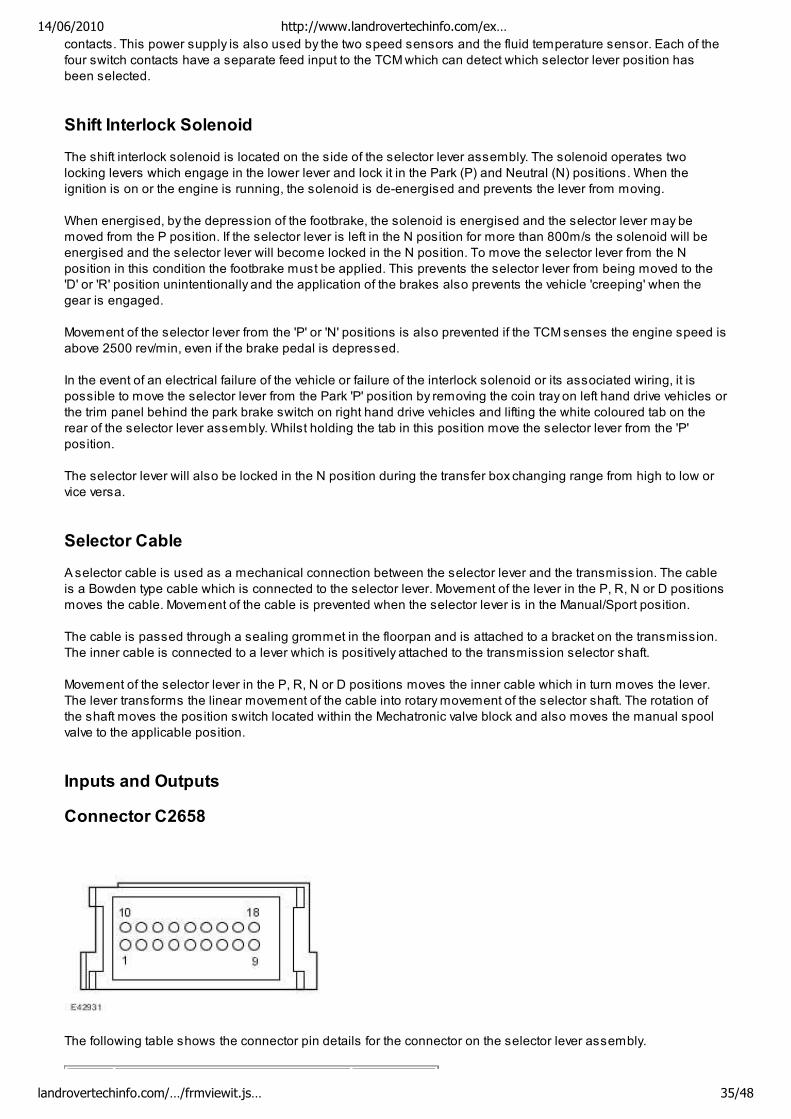
Inputs and Outputs
Connector C2658
The following table shows the connector pin details for the connector on the selector lever assembly.
14/06/2010 http://www.landrovertechinfo.com/ex…
landrovertechinfo.com/…/frmviewit.js… 35/48
Pin No. Description Input/Output
1 Ground -
2 Park lock confirmation Input
3 Ground -
4 Sport/Manual switch Output
5 CommandShift™ + (up shift) Output
6 CommandShift™ - (down shift) Output
7 Ignition position II supply 12V Input
8 Permanent power supply 12V Input
9 Shift Interlock solenoid + Input
10 Shift Interlock solenoid - Input
11 Selector indicator PARK LED Output
12 Selector indicator REVERSE LED Output
13 Selector indicator NEUTRAL LED Output
14 Selector indicator DRIVE LED Output
15 Selector indicator SPORT/MANUAL LED Output
16 Selector indicator backlight Output - PWM
17 - 18 Not used -
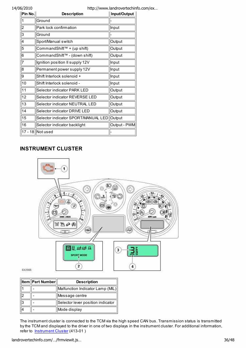
INSTRUMENT CLUSTER
Item Part Number Description
1 - Malfunction Indicator Lamp (MIL)
2 - Message centre
3 - Selector lever position indicator
4 - Mode display
The instrument cluster is connected to the TCM via the high speed CAN bus. Transmission status is transmitted
by the TCM and displayed to the driver in one of two displays in the instrument cluster. For additional information,
refer to Instrument Cluster (413-01 )
14/06/2010 http://www.landrovertechinfo.com/ex…
landrovertechinfo.com/…/frmviewit.js… 36/48
Malfunction Indicator Lamp (MIL)
The MIL is located in the tachometer in the instrument cluster. Transmission related faults which may affect the
vehicle emissions output will illuminate the MIL.
The MIL is illuminated by the ECM on receipt of a relevant fault message from the TCM on the high speed CAN.
The nature of the fault can be diagnosed using T4 which reads the fault codes stored in the TCM memory.
Transmission Status Display
The transmission status display is located in a Liquid Crystal Display (LCD) within the speedometer housing. The
LCD shows the selector lever position and the selected transmission mode. When the selector lever is in the
manual CommandShift™ position, the selector lever position display will show the selected gear ratio.
The following table shows the displays and their descriptions.
Symbol Description
P Park selected
R Reverse selected
N Neutral selected
D Drive selected
1 1st gear selected (Manual CommandShift™ mode)
2 2nd gear selected (Manual CommandShift™ mode)
3 3rd gear selected (Manual CommandShift™ mode)
4 4th gear selected (Manual CommandShift™ mode)
5 5th gear selected (Manual CommandShift™ mode)
6 6th gear selected (Manual CommandShift™ mode)
Message Centre Display
The message centre is located in the lower centre of the instrument cluster. The message centre is a LCD to relay
vehicle status and operating information to the driver. The message centre can display messages relating to a
number of the vehicle systems. The following list shows the possible transmission related messages:
TRANSMISSION FAULT LIMITED GEARS AVAILABLE
TRANSMISSION FAULT AND OVERHEAT
TRANSMISSION FAULT
TRANSMISSION OVERHEAT
TRANSMISSION CONTROL MODULE (TCM)
The TCM is an integral part of the Mechatronic valve block which is located at the bottom of the transmission,
behind the fluid pan. The TCM is the main controlling component of the transmission.
The TCM processes signals from the transmission speed and temperature sensors, engine control module and
other vehicle systems. From the received signal inputs and pre-programmed data, the module calculates the
correct gear, torque converter clutch setting and optimum pressure settings for gear shift and lock-up clutch
control.
The TCM outputs signals to control the shift control solenoid valve and the Electronic Pressure Regulator
Solenoids (EPRS) to control the hydraulic operation of the transmission.
The ECM supplies the engine management data on the high speed CAN bus system. The TCM requires engine
data to efficiently control the transmission operation, for example; flywheel torque, engine speed, accelerator pedal
14/06/2010 http://www.landrovertechinfo.com/ex…
landrovertechinfo.com/…/frmviewit.js… 37/48
angle, engine temperature etc.
The steering angle sensor and the ABS module also supply data to the TCM on the high speed CAN bus sytem.
The TCM uses data from these systems to suspend gear changes when the vehicle is cornering and/or the ABS
module is controlling braking or traction control.
The selector lever is connected to the automatic transmission and the position switch in the transmission by a
Bowden cable. Movement of the selector lever moves the position switch via the Bowden cable and the switch
position informs the TCM of the selected position. The sport/manual +/- CommandShift switch passes
manual/sport selections to the TCM. An additional switch provides a selector lever in park position signal. Once
the selector lever position is confirmed, the TCM outputs appropriate information which is received by the
instrument cluster to display the gear selection information in the message centre.
The Mechatronic valve block also contains the speed and temperature sensors. These are integral with the
Mechatronic valve block and cannot be serviced individually. The speed sensors measure the transmission input
and output speeds and pass signals to the TCM. The fluid temperature sensor is also located in the valve block
and measures the fluid temperature of the transmission fluid in the fluid pan.
The TCM is connected to the starter relay coil. When the selector lever is in PARK or NEUTRAL, the module
provides a ground for the coil allowing the starter relay to be energised and allow starter motor operation. If the
selector lever is in any other position, the module will not provide the ground preventing starter motor operation.
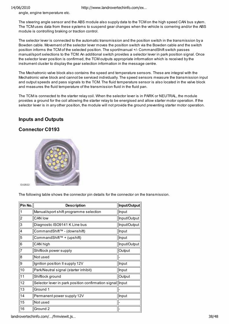
Inputs and Outputs
Connector C0193
The following table shows the connector pin details for the connector on the transmission.
Pin No. Description Input/Output
1 Manual/sport shift programme selection Input
2 CAN low Input/Output
3 Diagnostic ISO9141 K Line bus Input/Output
4 CommandShift™ - (downshift) Input
5 CommandShift™ + (upshift) Input
6 CAN high Input/Output
7 Shiftlock power supply Output
8 Not used -
9 Ignition position II supply 12V Input
10 Park/Neutral signal (starter inhibit) Input
11 Shiftlock ground Output
12 Selector lever in park position confirmation signal Input
13 Ground 1 -
14 Permanent power supply 12V Input
15 Not used -
16 Ground 2 -
14/06/2010 http://www.landrovertechinfo.com/ex…
landrovertechinfo.com/…/frmviewit.js… 38/48
DIAGNOSTICS
The diagnostic socket is located in the lower instrument panel closing panel, on the driver's side, below the
steering column.
The diagnostic socket allows the exchange of information between the various modules on the bus systems and
T4 or a diagnostic tool using ISO14229 protocol. The information is communicated to the socket via the high
speed CAN bus from the TCM. This allows the retrieval of diagnostic information and programming of certain
functions using T4 or a suitable diagnostic tool.
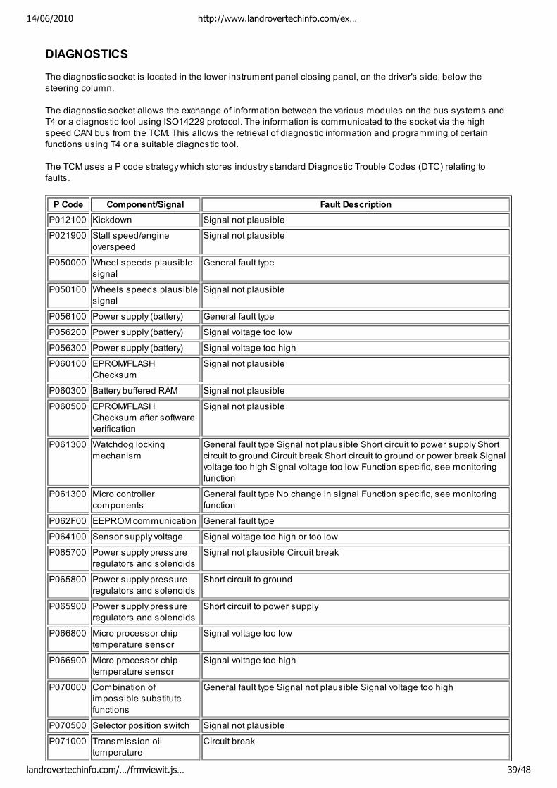
The TCM uses a P code strategy which stores industry standard Diagnostic Trouble Codes (DTC) relating to
faults.
P Code Component/Signal Fault Description
P012100 Kickdown Signal not plausible
P021900 Stall speed/engine
overspeed
Signal not plausible
P050000 Wheel speeds plausible
signal
General fault type
P050100 Wheels speeds plausible
signal
Signal not plausible
P056100 Power supply (battery) General fault type
P056200 Power supply (battery) Signal voltage too low
P056300 Power supply (battery) Signal voltage too high
P060100 EPROM/FLASH
Checksum
Signal not plausible
P060300 Battery buffered RAM Signal not plausible
P060500 EPROM/FLASH
Checksum after software
verification
Signal not plausible
P061300 Watchdog locking
mechanism
General fault type Signal not plausible Short circuit to power supply Short
circuit to ground Circuit break Short circuit to ground or power break Signal
voltage too high Signal voltage too low Function specific, see monitoring
function
P061300 Micro controller
components
General fault type No change in signal Function specific, see monitoring
function
P062F00 EEPROM communication General fault type
P064100 Sensor supply voltage Signal voltage too high or too low
P065700 Power supply pressure
regulators and solenoids
Signal not plausible Circuit break
P065800 Power supply pressure
regulators and solenoids
Short circuit to ground
P065900 Power supply pressure
regulators and solenoids
Short circuit to power supply
P066800 Micro processor chip
temperature sensor
Signal voltage too low
P066900 Micro processor chip
temperature sensor
Signal voltage too high
P070000 Combination of
impossible substitute
functions
General fault type Signal not plausible Signal voltage too high
P070500 Selector position switch Signal not plausible
P071000 Transmission oil
temperature
Circuit break
14/06/2010 http://www.landrovertechinfo.com/ex…
landrovertechinfo.com/…/frmviewit.js… 39/48
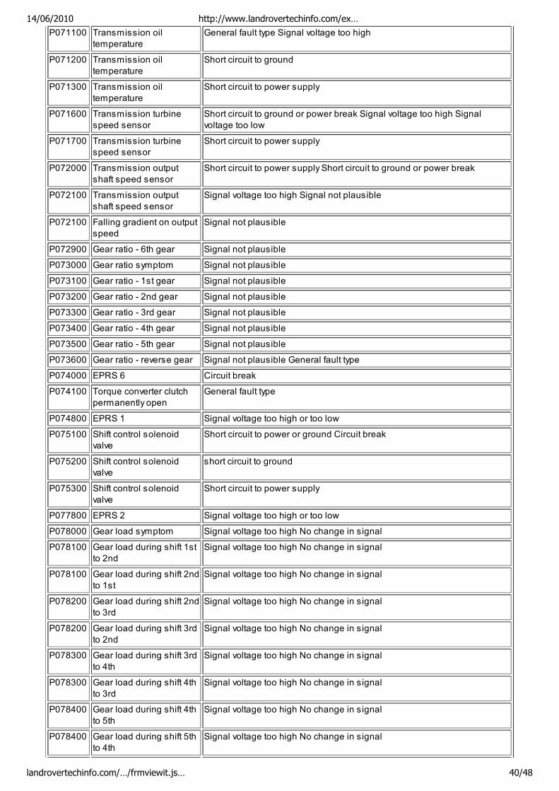
P071100 Transmission oil
temperature
General fault type Signal voltage too high
P071200 Transmission oil
temperature
Short circuit to ground
P071300 Transmission oil
temperature
Short circuit to power supply
P071600 Transmission turbine
speed sensor
Short circuit to ground or power break Signal voltage too high Signal
voltage too low
P071700 Transmission turbine
speed sensor
Short circuit to power supply
P072000 Transmission output
shaft speed sensor
Short circuit to power supply Short circuit to ground or power break
P072100 Transmission output
shaft speed sensor
Signal voltage too high Signal not plausible
P072100 Falling gradient on output
speed
Signal not plausible
P072900 Gear ratio - 6th gear Signal not plausible
P073000 Gear ratio symptom Signal not plausible
P073100 Gear ratio - 1st gear Signal not plausible
P073200 Gear ratio - 2nd gear Signal not plausible
P073300 Gear ratio - 3rd gear Signal not plausible
P073400 Gear ratio - 4th gear Signal not plausible
P073500 Gear ratio - 5th gear Signal not plausible
P073600 Gear ratio - reverse gear Signal not plausible General fault type
P074000 EPRS 6 Circuit break
P074100 Torque converter clutch
permanently open
General fault type
P074800 EPRS 1 Signal voltage too high or too low
P075100 Shift control solenoid
valve
Short circuit to power or ground Circuit break
P075200 Shift control solenoid
valve
short circuit to ground
P075300 Shift control solenoid
valve
Short circuit to power supply
P077800 EPRS 2 Signal voltage too high or too low
P078000 Gear load symptom Signal voltage too high No change in signal
P078100 Gear load during shift 1st
to 2nd
Signal voltage too high No change in signal
P078100 Gear load during shift 2nd
to 1st
Signal voltage too high No change in signal
P078200 Gear load during shift 2nd
to 3rd
Signal voltage too high No change in signal
P078200 Gear load during shift 3rd
to 2nd
Signal voltage too high No change in signal
P078300 Gear load during shift 3rd
to 4th
Signal voltage too high No change in signal
P078300 Gear load during shift 4th
to 3rd
Signal voltage too high No change in signal
P078400 Gear load during shift 4th
to 5th
Signal voltage too high No change in signal
P078400 Gear load during shift 5th
to 4th
Signal voltage too high No change in signal
14/06/2010 http://www.landrovertechinfo.com/ex…
landrovertechinfo.com/…/frmviewit.js… 40/48
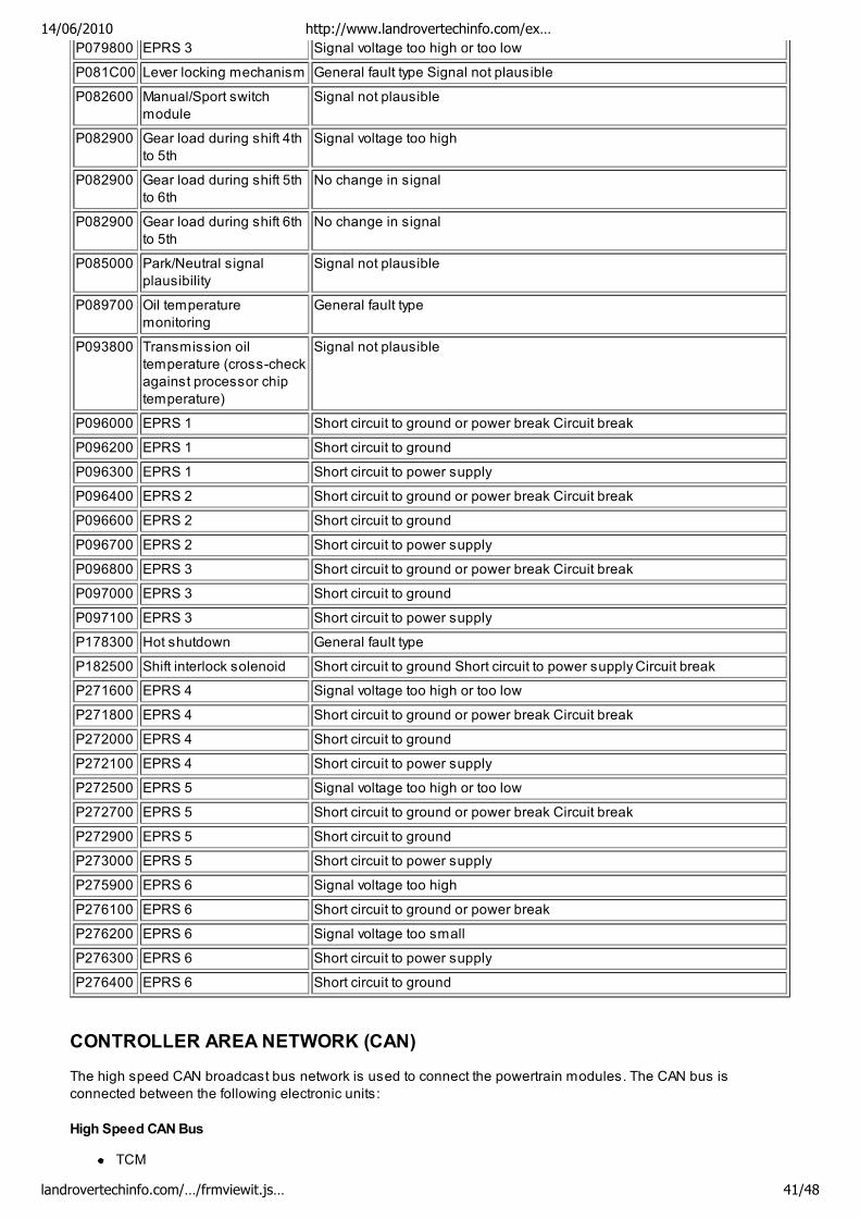
P079800 EPRS 3 Signal voltage too high or too low
P081C00 Lever locking mechanism General fault type Signal not plausible
P082600 Manual/Sport switch
module
Signal not plausible
P082900 Gear load during shift 4th
to 5th
Signal voltage too high
P082900 Gear load during shift 5th
to 6th
No change in signal
P082900 Gear load during shift 6th
to 5th
No change in signal
P085000 Park/Neutral signal
plausibility
Signal not plausible
P089700 Oil temperature
monitoring
General fault type
P093800 Transmission oil
temperature (cross-check
against processor chip
temperature)
Signal not plausible
P096000 EPRS 1 Short circuit to ground or power break Circuit break
P096200 EPRS 1 Short circuit to ground
P096300 EPRS 1 Short circuit to power supply
P096400 EPRS 2 Short circuit to ground or power break Circuit break
P096600 EPRS 2 Short circuit to ground
P096700 EPRS 2 Short circuit to power supply
P096800 EPRS 3 Short circuit to ground or power break Circuit break
P097000 EPRS 3 Short circuit to ground
P097100 EPRS 3 Short circuit to power supply
P178300 Hot shutdown General fault type
P182500 Shift interlock solenoid Short circuit to ground Short circuit to power supply Circuit break
P271600 EPRS 4 Signal voltage too high or too low
P271800 EPRS 4 Short circuit to ground or power break Circuit break
P272000 EPRS 4 Short circuit to ground
P272100 EPRS 4 Short circuit to power supply
P272500 EPRS 5 Signal voltage too high or too low
P272700 EPRS 5 Short circuit to ground or power break Circuit break
P272900 EPRS 5 Short circuit to ground
P273000 EPRS 5 Short circuit to power supply
P275900 EPRS 6 Signal voltage too high
P276100 EPRS 6 Short circuit to ground or power break
P276200 EPRS 6 Signal voltage too small
P276300 EPRS 6 Short circuit to power supply
P276400 EPRS 6 Short circuit to ground
CONTROLLER AREA NETWORK (CAN)
The high speed CAN broadcast bus network is used to connect the powertrain modules. The CAN bus is
connected between the following electronic units:
High Speed CAN Bus
TCM
14/06/2010 http://www.landrovertechinfo.com/ex…
landrovertechinfo.com/…/frmviewit.js… 41/48
Instrument cluster
Air suspension module
Steering angle sensor
Rear differential module
Centre console switch pack
Electric park brake module
Restraints control module
Engine Control Module (ECM)
ABS control module
Adaptive front lighting control module
Transfer box control module
Adaptive cruise control module
Diagnostic socket.
The CAN bus allows a fast exchange of data between modules. The CAN bus comprises two wires which are
identified as CAN high (H) and CAN low (L). The two wires are coloured yellow/black (H) and yellow/brown (L) and
are twisted together to minimise electromagnetic interference (noise) produced by the CAN bus messages. For
additional information, refer to Communications Network (418-00 )
In the event of CAN bus failure, the following symptoms may be observed:
Transmission operates in default mode
Torque converter lock-up clutch control is disabled
Gear position indication in instrument cluster message centre inoperative (this will also occur with any
transmission fault).
DRIVING MODES
There are a number of different driving modes of operation. Some can be selected by the driver and some are
automatically initiated by the TCM during driving:
Normal mode
Sport mode
Manual (CommandShift™) mode
Adaptive Shift Strategy (ASIS)
Hill Descent Control (HDC) mode
Cruise mode
Hill mode
Default (Limp home) mode
Reverse lock-out mode
Cooling strategy.
Curve recognition mode
Fast off recognition
Normal Mode
Normal mode is automatically selected by the TCM on power up. In this mode all automatic and adaptive modes
are active. Normal mode uses gear shift and lock-up maps to allow for vehicle operation which offers fuel
consumption and emissions or driveability depending on the driving style. If the transmission is operated in sport
or manual mode and the selector lever is moved to the 'D' position, normal mode is automatically resumed.
Sport Mode
The sport mode operates in high range only and provides enhanced acceleration and responsiveness. In sport
mode the TCM uses shift maps which allow the transmission to downshift more readily, hold gears for longer at
higher engine speeds, and limits the transmission to the first five gears (6th gear is not used).
Sport mode is selected by moving the selector lever to the left into the 'M/S' position. When the sport mode is first
selected, 'SPORT' is displayed in the message centre for 6 seconds and, if 6th gear is currently engaged, the TCM
downshifts to 5th.
14/06/2010 http://www.landrovertechinfo.com/ex…
landrovertechinfo.com/…/frmviewit.js… 42/48
Manual (CommandShift™) Mode
Manual mode allows the transmission to operate as a semi-automatic 'CommandShift™' unit. The driver can
change up and down the six forward gears with the freedom of a manual transmission.
Shift maps are provided for manual mode to protect the engine at high engine speeds. The TCM will automatically
change up to a higher gear ratio to prevent engine overspeed and change down to a lower gear ratio to avoid
engine labouring and stalling.
When kickdown is requested the TCM downshifts at least 2 gears.
When the vehicle is stationary, to drive off the driver can select 1st , 2nd or 3rd gear in low and high range. Any
other gear selection will be rejected by the TCM.
When driving off, upshifts can be pre-selected by making + selections with the selector lever for the number of
upshifts required. The TCM then automatically performs a corresponding number of upshifts when the appropriate
shift points are reached. So, for example, when starting off in 1st gear, if three + selections are made in quick
succession, the TCM will automatically change up through the box to 4th gear as the vehicle accelerates, without
any further selections being made.
In manual mode a low gear can be selected to provide engine braking for descending a slope without HDC or
continuous use of the brake pedal. The driver can prepare for the end of the descent by moving the selector lever to
D. The TCM will maintain the low gear and only revert to automatic shift control when the throttle is opened and
vehicle speed increases.
Adaptive Shift Strategy (ASIS)
The ASIS system is a new feature on automatic transmissions. With the TCM linked via the CAN bus to other
vehicle systems, signals are received which can allow the TCM to calculate the way in which the vehicle is being
driven. The type of signals include the following:
Longitudinal and lateral acceleration
Engine speed
Engine torque
Oil temperature
Accelerator pedal position
Wheel speed.
Using these signals, additional transmission control can be obtained. The TCM can calculate when the vehicle is
cornering, all wheels are gripping, the driver is braking or if the driver is accelerating. This is the conventional
'Adaptive' transmission control. ASIS uses this system but adds the continuous adaptation of the gear changes to
the individual driving style of the driver.
HDC Mode
The HDC mode assists the ABS module in controlling the downhill speed of the vehicle. When HDC is selected
on, the ABS module selects the most appropriate gear for the descent, to maximise engine braking.
Cruise Mode
When speed control is activated, the TCM receives a cruise active message on the CAN bus. The TCM activates a
speed control map which prevents locking and unlocking of the torque converter clutch and minimises up and
down shifts.
Hill Mode
Hill mode is initiated by the TCM when the engine torque, via ECM signals on the CAN bus, exceeds the theoretical
load curve for normal operation. The TCM monitors this signal to determine when the vehicle is travelling up or
down a steep gradient.
14/06/2010 http://www.landrovertechinfo.com/ex…
landrovertechinfo.com/…/frmviewit.js… 43/48
In hill mode the TCM adopts one of four shift maps, three uphill and one downhill. The shift map chosen depends
on the severity of the slope as determined from the engine signals and the appropriate gear is selected to assist
with the ascent or descent.
Hill mode can also be initiated when the vehicle is at very high altitudes or ambient temperatures, and also when
the vehicle is towing.
Default (Limp Home) Mode
If a transmission fault is detected by the TCM, the TCM adopts a limp home mode strategy. 'TRANS. FAILSAFE' is
displayed in the message centre and, if the fault has an effect on engine emissions, the MIL will also be
illuminated.
In default mode, P, R and N functions operate normally (if the fault allows these selections) and the TCM locks the
transmission in 3rd or 5th gear to allow the driver to take the vehicle to the nearest dealer. The torque converter
lock-up clutch is disabled and reverse lock-out will not function.
If the vehicle is stopped and subsequently restarted in the default mode condition, the TCM operates normally until
the fault which caused the condition is detected again.
When limp home mode is active, the gear position indicator will show one of the following letters which defines the
fault type:
'F' - transmission is operating in limp home mode
'H' - transmission has reached overheat threshold temperature and transmission is operating in limp
home mode
'E' - CAN bus is off and transmission is operating in limp home mode.
If electrical power is lost and the transmission is operating in mechanical limp home mode, the selector lever will
not be locked in the 'N' position by the shift interlock solenoid. The lever will be locked in the 'P' position and can
only be released by using the interlock emergency release lever or by correcting the electrical fault.
Reverse Lock-Out Mode
When the vehicle is travelling forwards, selecting reverse could cause transmission damage. To protect against
this, reverse gear is prohibited if the vehicle is travelling forwards at a road speed above 5 mph (8 km/h).
Cooling Strategy
The purpose of the cooling strategy is to reduce engine and transmission temperatures during high load
conditions, when towing a trailer for example. Under these conditions the engine and transmission may generate
excessive heat.
If the transmission fluid temperature increases to 125ºC (257ºF) or higher, the TCM employs the cooling strategy.
The message 'TRANSMISSION OVERHEAT' is displayed in the message center.
The strategy uses a specific shift and torque converter lock-up clutch map. This map allows torque converter clutch
lock-up and gear shifts to operate outside of their normal operation. This will reduce the engine speed and/or slip
in the torque converter, therefore reducing heat generated by the engine and the transmission.
If the transmission fluid temperature increases to 137ºC (278ºF) or higher, the transmission will use the default
(limp home mode). 'H' is displayed in the gear position indicator. If the temperature exceeds 140ºC (284ºF), CAN
bus transmission is disabled and 'E' is displayed in the gear position indicator.
The cooling strategy is cancelled when the transmission fluid temperature decreases to less than 120ºC (248ºF)
or below.
Curve Recognition
Curve recognition is activated when high levels of lateral acceleration and/or steering angle are detected via the
14/06/2010 http://www.landrovertechinfo.com/ex…
landrovertechinfo.com/…/frmviewit.js… 44/48
ABS module and steering angle sensor signals on the CAN bus. When this condition is detected, the TCM
prevents the transmission from changing to a higher gear to assist with cornering. When the vehicle completes it
manoeuvre, the transmission will shift to the correct ratio.
Fast Off Recognition
Fast off recognition is activated when the TCM detects that the driver has backed off the accelerator pedal quickly in
a 'change of mind' manoeuvre. This is detected by monitoring for a high level of negative pedal angle from the
engine control module signal on the CAN bus. If this condition is detected, the TCM holds the current gear ratio to
allow the driver to complete his original action without the need for a downshift. The mode remains active for a
predetermined time period or if the driving style remains passive.
Terrain Response™ Mode
If the vehicle has the Terrain Response system fitted, the following additional modes are available.For additional
information, refer to Ride and Handling Optimization (204-06 Ride and Handling Optimization)
Grass/Gravel/Snow
When the driver selects the Terrain Response grass/gravel/snow special program with the transfer box in either
high or low range, the TCM uses a specific set of shift and torque converter maps to optimise the delivery of torque
to the wheels and to minimise wheel slip in these terrains. To assist with the vehicle moving from a standstill, the
TCM automatically selects 2nd gear in high range and 3rd gear in low range. This special program is fully
integrated with hill mode to enhance vehicle control during ascents and descents.
Mud/Ruts
When the driver selects the Terrain Response mud/ruts special program with the transfer box in either high or low
range, the TCM uses a specific set of shift and torque converter maps to optimise vehicle traction in this terrain.
Sand
When the driver selects the Terrain Response sand special program with the transfer box in either high or low
range, the TCM uses a specific set of shift and torque converter maps to optimise the tractive performance in sand
by holding onto gears longer and downshifting more readily. This mode is fully integrated with the hill mode to
further enhance performance during ascents.
Rock Crawl
When the driver selects the Terrain Response rock crawl special program, which is only available with the transfer
box in low range, the TCM uses a specific shift map which maximises torque delivery at slow speeds associated
with this type of terrain.
TRANSMISSION FAULT STATUS
If the TCM detects a fault with the transmission system, it will enter a default mode to prevent further damage to the
transmission and allow the vehicle to be driven.
When a fault is detected a CAN message is sent from the TCM and is received by the instrument cluster. The
instrument cluster illuminates the MIL and displays 'TRANS. FAILSAFE' in the message centre.
Some transmission faults may not illuminate the MIL or display a fault message, but the driver may notice a
reduction in shift quality.
ENGINE SPEED AND TORQUE MONITORING
The ECM constantly supplies the TCM with information on engine speed and torque through messages on the
CAN bus. The TCM uses this information to calculate the correct and appropriate timing of shift changes.
If the messages are not received by the ECM, the TCM will implement a back-up strategy to protect the
14/06/2010 http://www.landrovertechinfo.com/ex…
landrovertechinfo.com/…/frmviewit.js… 45/48
transmission from damage and allow the vehicle to be driven.
In the event of an engine speed or torque signal failure, the transmission will adopt the electrical limp home mode
with the transmission operating in a fixed gear.
TOWING FOR RECOVERY
The following procedure must be used to ensure that the vehicle is towed in a safe condition and damage to the
vehicle transmission systems is prevented.
Secure the towing attachment from the recovery vehicle to the towing eye of the vehicle to be recovered.
Make sure that the hand brake is on. Turn the ignition key to the ignition position II.
Apply the footbrake and move the automatic transmission selector lever to the neutral position. If electrical
power is not available, use the manual interlock release tab on the selector lever to move the lever to the
neutral position.
Make sure that the ignition is in the auxiliary position I or, if the stop lamps and turn signal indicators are
required, in the ignition position II.
Make sure that the hand brake is released before the vehicle is towed.
The vehicle can only be towed for a maximum of 31 miles (50 km) at a maximum speed of 30 mph (50
km/h). Towing the vehicle for longer distances and/or faster speeds will damage the transmission.
WARNING: Do not remove the key or move the ignition switch to position 'O' when the vehicle is being
towed. The steering lock will be engaged preventing the steering from being turned. With the engine not
running, the brake booster and power steering pump will be inoperative. Care must be taken to ensure the
vehicle is manoeuvred and driven accordingly.
CONTROL DIAGRAM
NOTE:
A = Hardwired; D= High Speed CAN Bus
14/06/2010 http://www.landrovertechinfo.com/ex…
landrovertechinfo.com/…/frmviewit.js… 46/48
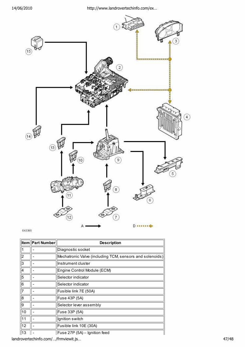
Item Part Number Description
1 - Diagnostic socket
2 - Mechatronic Valve (including TCM, sensors and solenoids)
3 - Instrument cluster
4 - Engine Control Module (ECM)
5 - Selector indicator
6 - Selector indicator
7 - Fusible link 7E (50A)
8 - Fuse 43P (5A)
9 - Selector lever assembly
10 - Fuse 33P (5A)
11 - Ignition switch
12 - Fusible link 10E (30A)
13 - Fuse 27P (5A) – Ignition feed
14/06/2010 http://www.landrovertechinfo.com/ex…
landrovertechinfo.com/…/frmviewit.js… 47/48
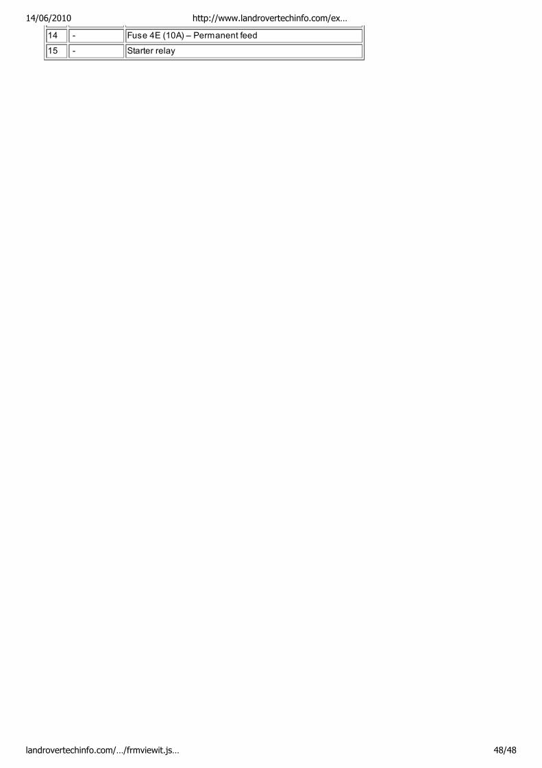
14 - Fuse 4E (10A) – Permanent feed
15 - Starter relay
14/06/2010 http://www.landrovertechinfo.com/ex…
landrovertechinfo.com/…/frmviewit.js… 48/48