Embed Size (px)
Citation preview
Andrzej Przepiora and Jeff Roberts
Zero-Valent Iron for Groundwater
Remediation – Lessons Learned over 20 years
of Technology Use
RemTech 2016
Oct. 12-14, 2016
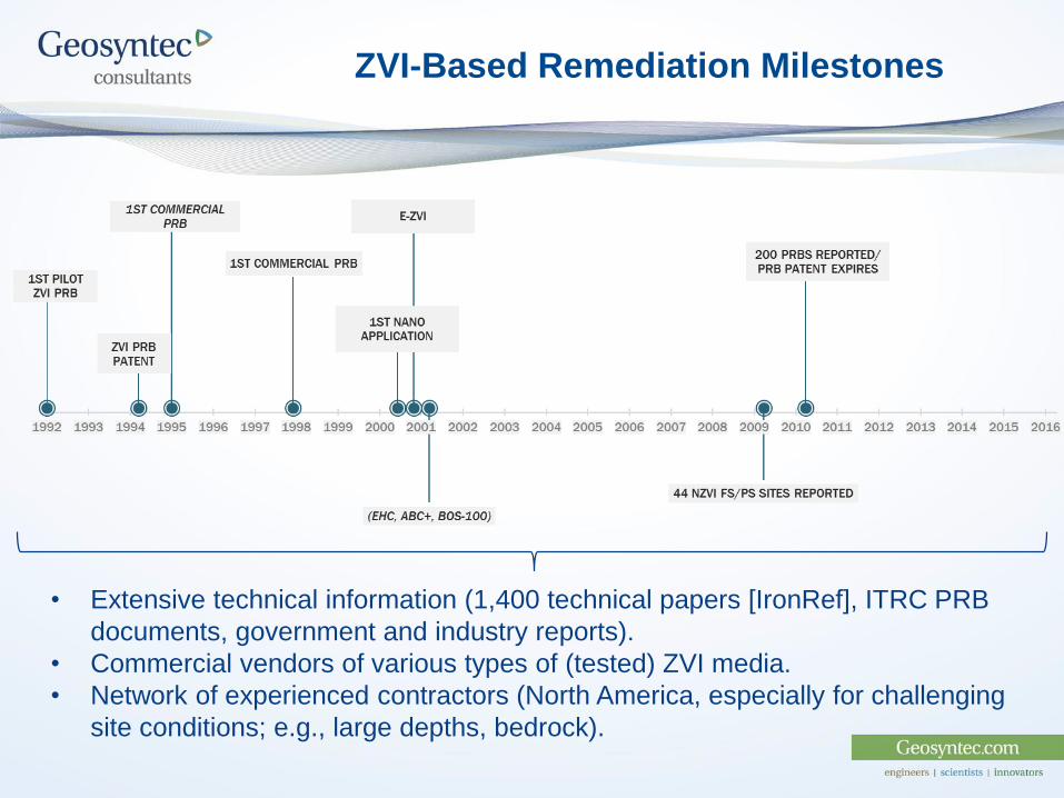
ZVI-Based Remediation Milestones
• Extensive technical information (1,400 technical papers [IronRef], ITRC PRB
documents, government and industry reports).
• Commercial vendors of various types of (tested) ZVI media.
• Network of experienced contractors (North America, especially for challenging
site conditions; e.g., large depths, bedrock).
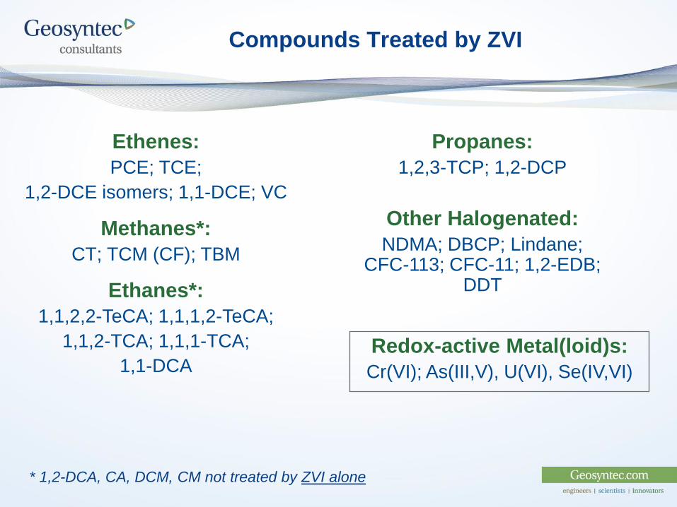
Compounds Treated by ZVI
Ethenes:
PCE; TCE;
1,2-DCE isomers; 1,1-DCE; VC
Methanes*:
CT; TCM (CF); TBM
Ethanes*:
1,1,2,2-TeCA; 1,1,1,2-TeCA;
1,1,2-TCA; 1,1,1-TCA;
1,1-DCA
Propanes:
1,2,3-TCP; 1,2-DCP
Other Halogenated:
NDMA; DBCP; Lindane; CFC-113; CFC-11; 1,2-EDB;
DDT
* 1,2-DCA, CA, DCM, CM not treated by ZVI alone
Redox-active Metal(loid)s:
Cr(VI); As(III,V), U(VI), Se(IV,VI)
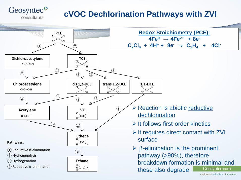
Reaction is abiotic reductive
dechlorination
It follows first-order kinetics
It requires direct contact with ZVI
surface
b-elimination is the prominent
pathway (>90%), therefore
breakdown formation is minimal and
these also degrade
cVOC Dechlorination Pathways with ZVI
Redox Stoichiometry (PCE):
4Fe0 4Fe2+ + 8e-
C2Cl4 + 4H+ + 8e- C2H4 + 4Cl-
cis 1,2-DCE 1,1-DCE trans 1,2-DCE
VC
Ethene
Chloroacetylene
Dichloroacetylene
Acetylene
PCE
TCE
Ethane
Cl
Cl
C=C Cl
Cl
Cl
Cl
C=C Cl
H
Cl
H
C=C Cl
H
Cl
H
C=C Cl
Cl
Cl
Cl
C=C H
H
Cl
H
C=C H
H
H
H
C=C H
H
④
③
② ②
② ② ②
②
②
②
②
①
①
①
Cl─C C─Cl
Cl─C C─H
H─C C─H
H
H
H ─C─C ─ H H
H
Pathways:
① Reductive ß-elimination
② Hydrogenolysis
③ Hydrogenation
④ Reductive -elimination
③

Types of ZVI Media and Their Applications
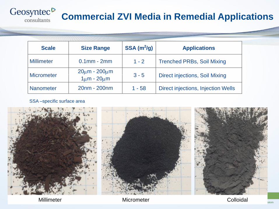
Commercial ZVI Media in Remedial Applications
Scale Size Range SSA (m2/g) Applications
Millimeter 0.1mm - 2mm 1 - 2 Trenched PRBs, Soil Mixing
Micrometer20m - 200m
3 - 5 Direct injections, Soil Mixing1m - 20m
Nanometer 20nm - 200nm 1 - 58 Direct injections, Injection Wells
SSA –specific surface area
Millimeter Micrometer Colloidal
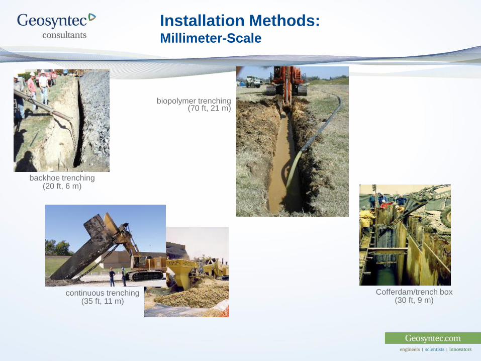
Installation Methods: Millimeter-Scale
backhoe trenching(20 ft, 6 m)
Cofferdam/trench box(30 ft, 9 m)
continuous trenching(35 ft, 11 m)
biopolymer trenching(70 ft, 21 m)

Installation Methods: Micro-, Nano-Scale
hydraulic fracturing/injection (120 ft, 37 m)
jetting techniques(60 ft, 18 m)
Pneumatic fracturing
(90 ft, 27 m)
Nitrogen
Gas Source
Overburden
Treatment ZoneIn j ec t o r
Atomized Slurry
in Gas Stream
Packer
Pneumatic
Injection Module
Ferox Injection
Trailer
Direct injection
(30 ft, 9 m)
In-well applications (Nano)

ZVI System Design
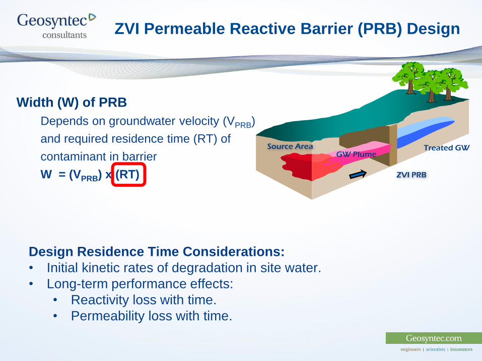
ZVI Permeable Reactive Barrier (PRB) Design
Width (W) of PRB
Depends on groundwater velocity (VPRB)
and required residence time (RT) of
contaminant in barrier
W = (VPRB) x (RT)
Source AreaGW Plume
Treated GW
ZVI PRB
Design Residence Time Considerations:
• Initial kinetic rates of degradation in site water.
• Long-term performance effects:
• Reactivity loss with time.
• Permeability loss with time.
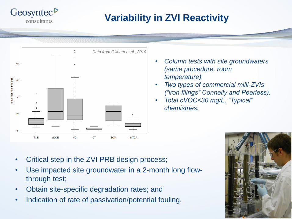
Variability in ZVI Reactivity
• Critical step in the ZVI PRB design process;
• Use impacted site groundwater in a 2-month long flow-
through test;
• Obtain site-specific degradation rates; and
• Indication of rate of passivation/potential fouling.
Data from Gillham et al., 2010
• Column tests with site groundwaters
(same procedure, room
temperature).
• Two types of commercial milli-ZVIs
(“iron filings” Connelly and Peerless).
• Total cVOC<30 mg/L, “Typical”
chemistries.
Factors Controlling ZVI PRB Performance
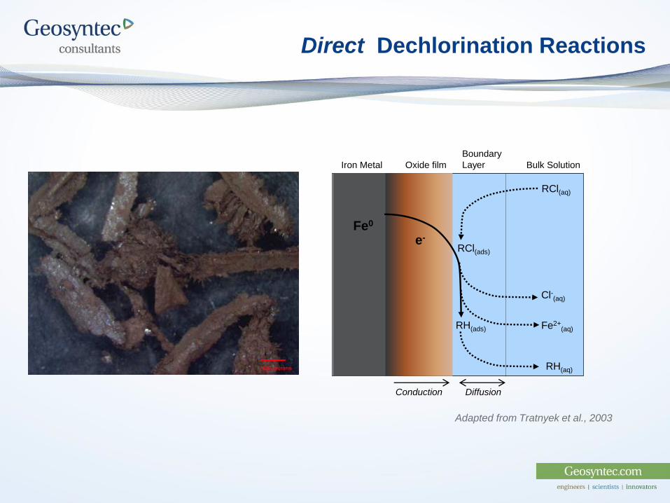
Direct Dechlorination Reactions
e-
RH(aq)
Adapted from Tratnyek et al., 2003
e-
Oxide film
Boundary
Layer Bulk SolutionIron Metal
Fe0
RCl(aq)
RH(ads) Fe2+(aq)
RCl(ads)
Cl-(aq)
Conduction Diffusion
RH(aq)
e-
4
5
6
7
8
9
10
-500
-400
-300
-200
-100
0
100
200
300
0 5 10 15 20 25
pH
OR
P (
mV
) ORP (mV)
pH
ZVI Residence Time (hours)
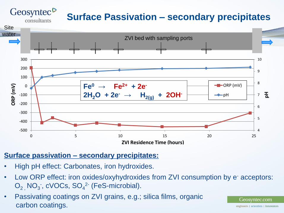
Surface Passivation – secondary precipitates
Fe0 → Fe2+ + 2e-
2H2O + 2e- → H2(g) + 2OH-
Surface passivation – secondary precipitates:
• High pH effect: Carbonates, iron hydroxides.
• Low ORP effect: iron oxides/oxyhydroxides from ZVI consumption by e- acceptors:
O2 , NO3-, cVOCs, SO4
2- (FeS-microbial).
• Passivating coatings on ZVI grains, e.g.; silica films, organic
carbon coatings.
ZVI bed with sampling ports
Site
water
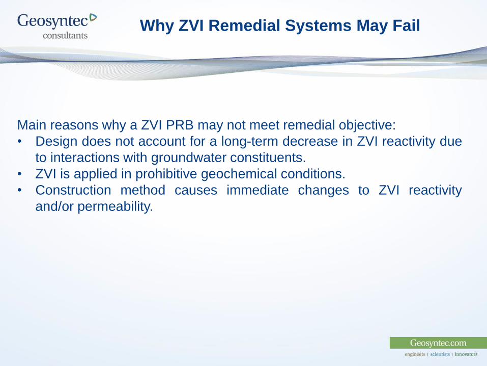
Why ZVI Remedial Systems May Fail
Main reasons why a ZVI PRB may not meet remedial objective:
• Design does not account for a long-term decrease in ZVI reactivity due
to interactions with groundwater constituents.
• ZVI is applied in prohibitive geochemical conditions.
• Construction method causes immediate changes to ZVI reactivity
and/or permeability.
ZVI PRB Performance:Long-Term Inorganic Chemistry Effects
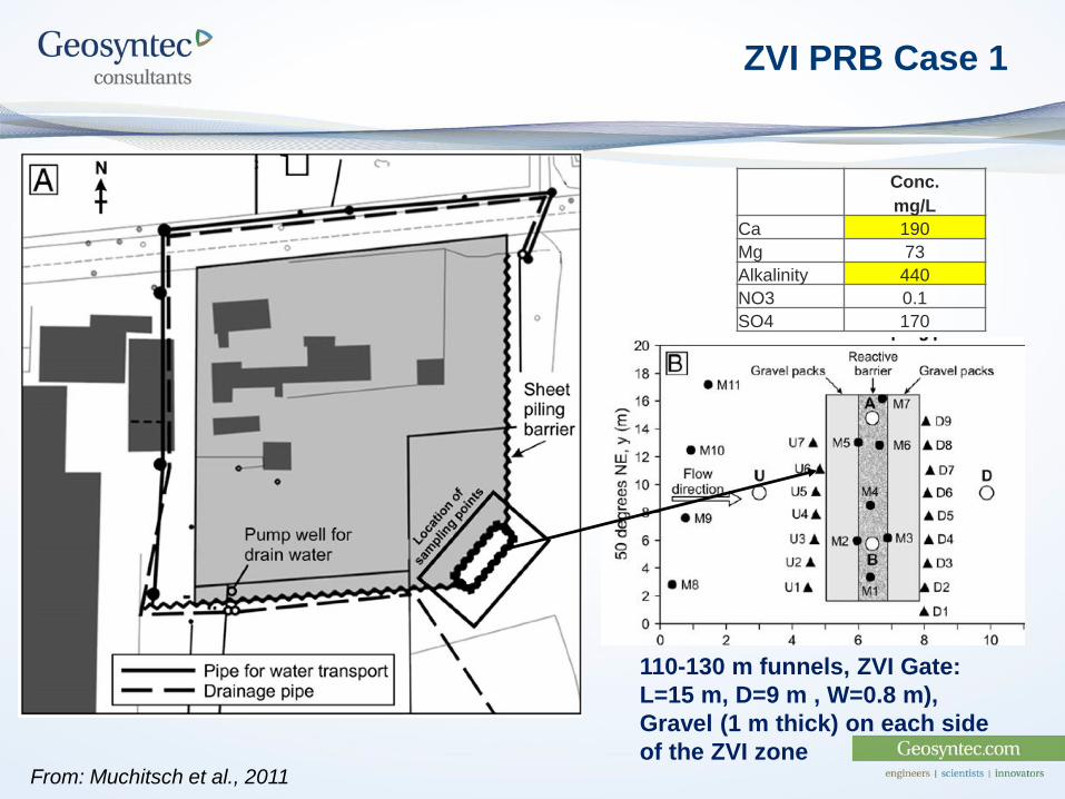
ZVI PRB Case 1
110-130 m funnels, ZVI Gate:
L=15 m, D=9 m , W=0.8 m),
Gravel (1 m thick) on each side
of the ZVI zoneFrom: Muchitsch et al., 2011
Conc.
mg/L
Ca 190
Mg 73
Alkalinity 440
NO3 0.1
SO4 170
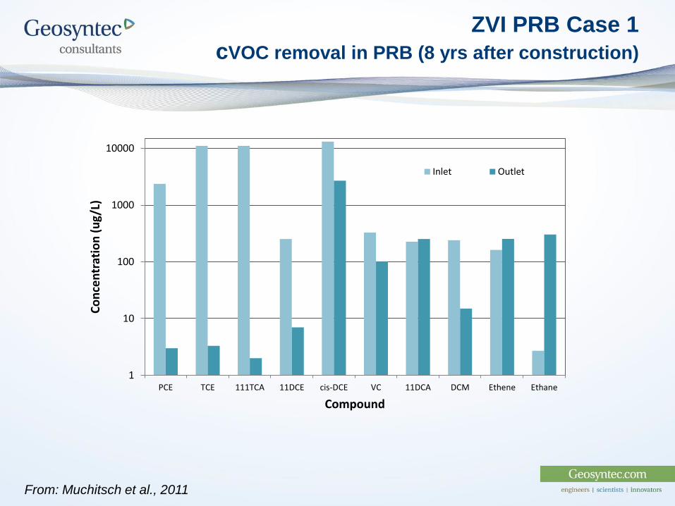
ZVI PRB Case 1
cVOC removal in PRB (8 yrs after construction)
From: Muchitsch et al., 2011
1
10
100
1000
10000
PCE TCE 111TCA 11DCE cis-DCE VC 11DCA DCM Ethene Ethane
Co
nce
ntr
atio
n (
ug/
L)
Compound
Inlet Outlet
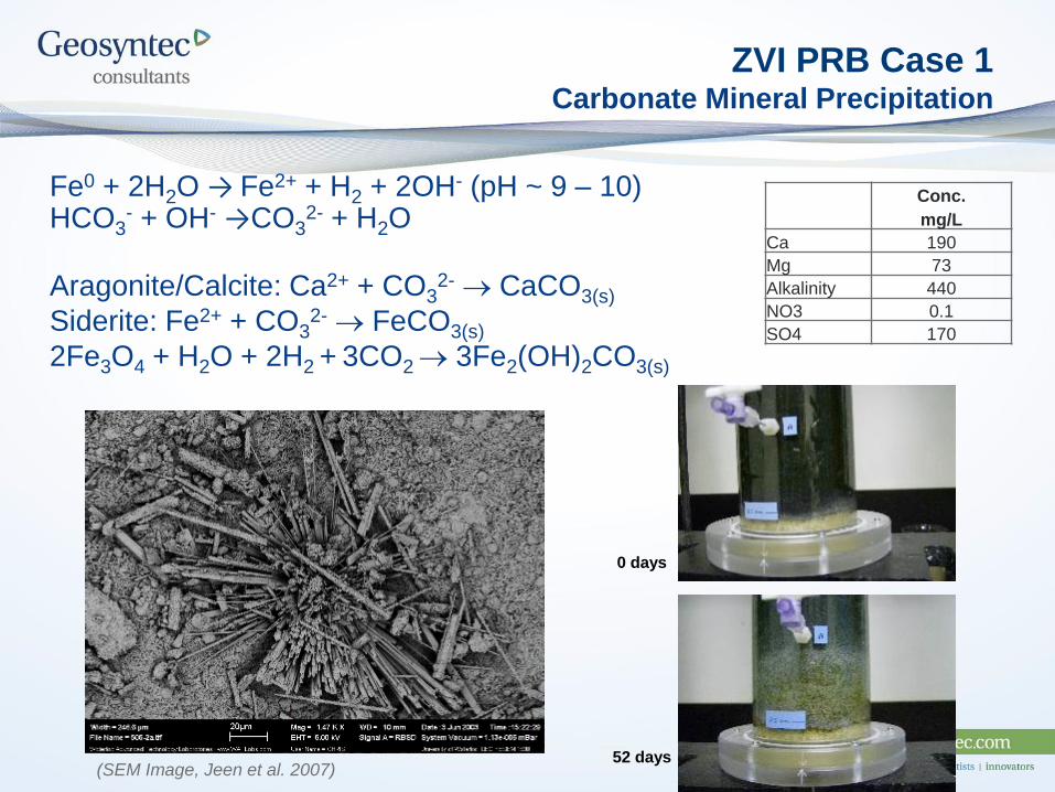
ZVI PRB Case 1Carbonate Mineral Precipitation
Fe0 + 2H2O → Fe2+ + H2 + 2OH- (pH ~ 9 – 10)HCO3
- + OH- →CO32- + H2O
Aragonite/Calcite: Ca2+ + CO32- CaCO3(s)
Siderite: Fe2+ + CO32- FeCO3(s)
2Fe3O4 + H2O + 2H2 + 3CO2 3Fe2(OH)2CO3(s)
(SEM Image, Jeen et al. 2007)
Conc.
mg/L
Ca 190
Mg 73
Alkalinity 440
NO3 0.1
SO4 170
0 days
52 days
ZVI PRB Performance:Effects of Prohibitive Constituents
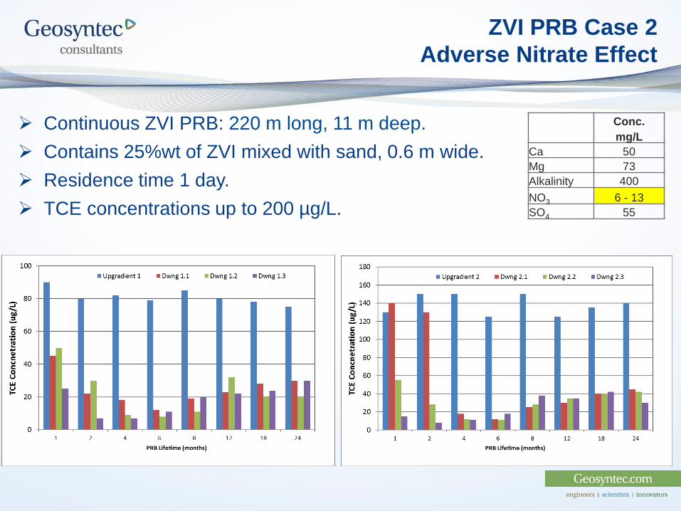
ZVI PRB Case 2
Adverse Nitrate Effect
Conc.
mg/L
Ca 50
Mg 73
Alkalinity 400
NO3 6 - 13
SO4 55
Continuous ZVI PRB: 220 m long, 11 m deep.
Contains 25%wt of ZVI mixed with sand, 0.6 m wide.
Residence time 1 day.
TCE concentrations up to 200 µg/L.
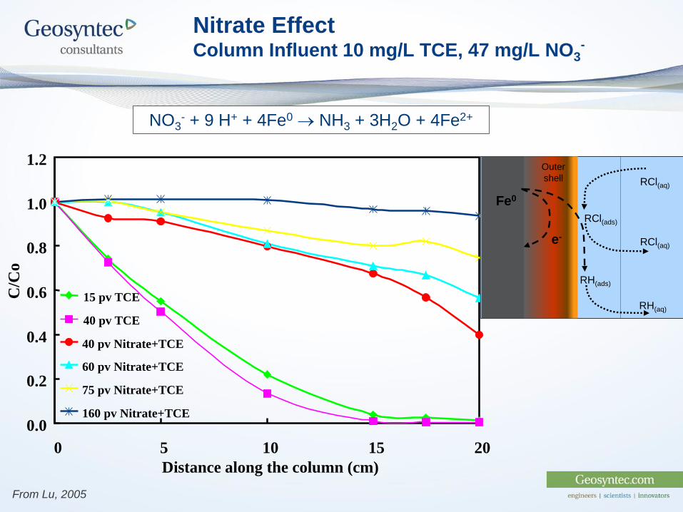
Nitrate EffectColumn Influent 10 mg/L TCE, 47 mg/L NO3
-
0.0
0.2
0.4
0.6
0.8
1.0
1.2
0 5 10 15 20
Distance along the column (cm)
C/C
o
15 pv TCE
40 pv TCE
40 pv Nitrate+TCE
60 pv Nitrate+TCE
75 pv Nitrate+TCE
160 pv Nitrate+TCE
From Lu, 2005
NO3- + 9 H+ + 4Fe0 NH3 + 3H2O + 4Fe2+
Outer
shell
Fe0
RCl(aq)
RH(ads)
RCl(ads)
e-RCl(aq)
RH(aq)
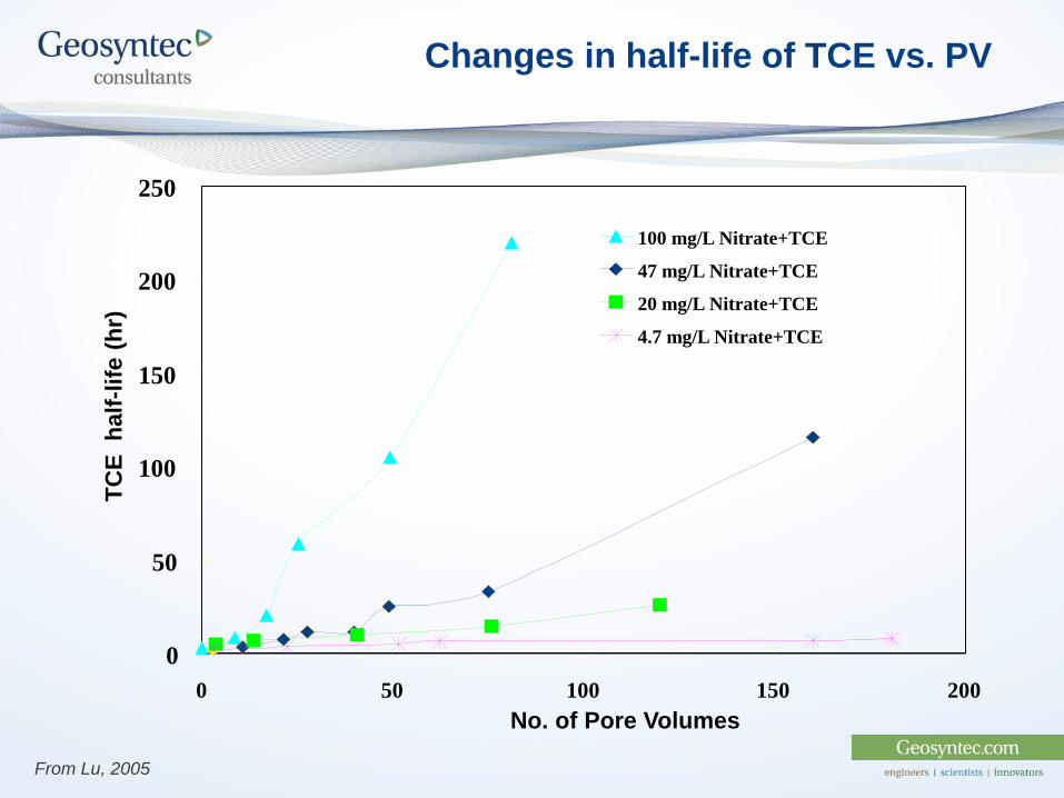
Changes in half-life of TCE vs. PV
0
50
100
150
200
250
0 50 100 150 200
No. of Pore Volumes
TC
E
half
-lif
e (
hr)
100 mg/L Nitrate+TCE
47 mg/L Nitrate+TCE
20 mg/L Nitrate+TCE
4.7 mg/L Nitrate+TCE
From Lu, 2005
ZVI PRB Performance:Construction Artifacts
ZVI PRB Case 3
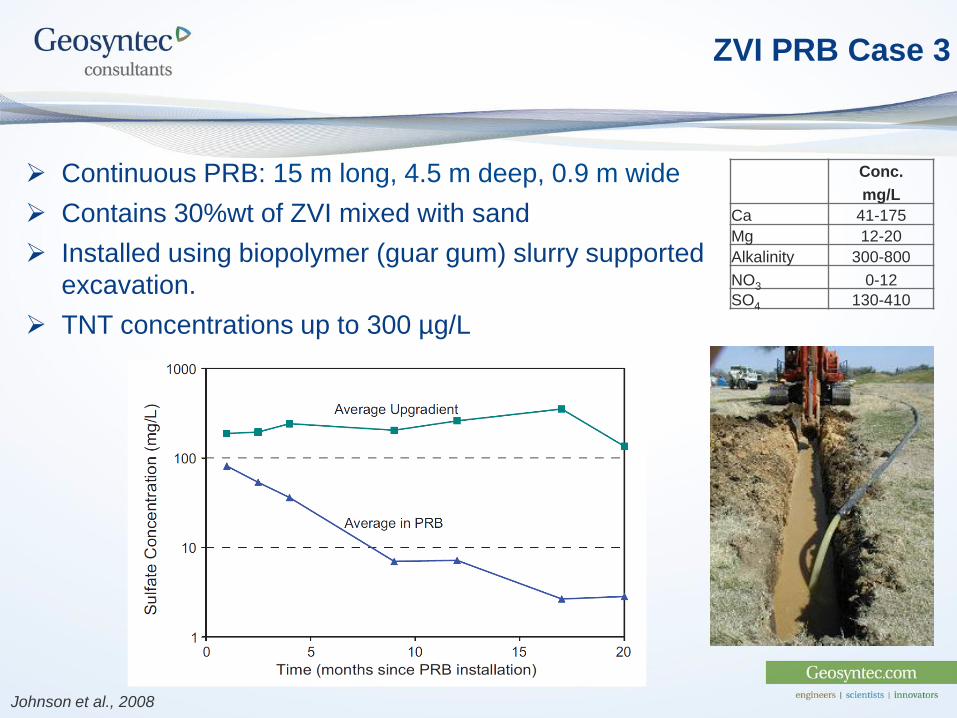
Conc.
mg/L
Ca 41-175
Mg 12-20
Alkalinity 300-800
NO3 0-12
SO4 130-410
Continuous PRB: 15 m long, 4.5 m deep, 0.9 m wide
Contains 30%wt of ZVI mixed with sand
Installed using biopolymer (guar gum) slurry supported
excavation.
TNT concentrations up to 300 µg/L
Johnson et al., 2008
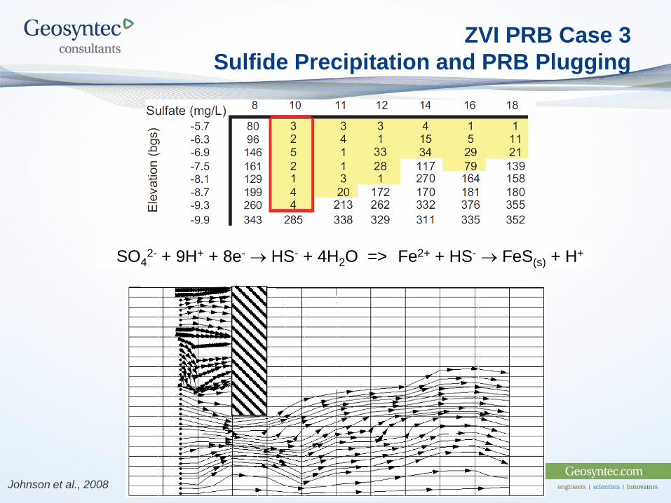
ZVI PRB Case 3
Sulfide Precipitation and PRB Plugging
Johnson et al., 2008
SO42- + 9H+ + 8e- HS- + 4H2O => Fe2+ + HS- FeS(s) + H+

Summary
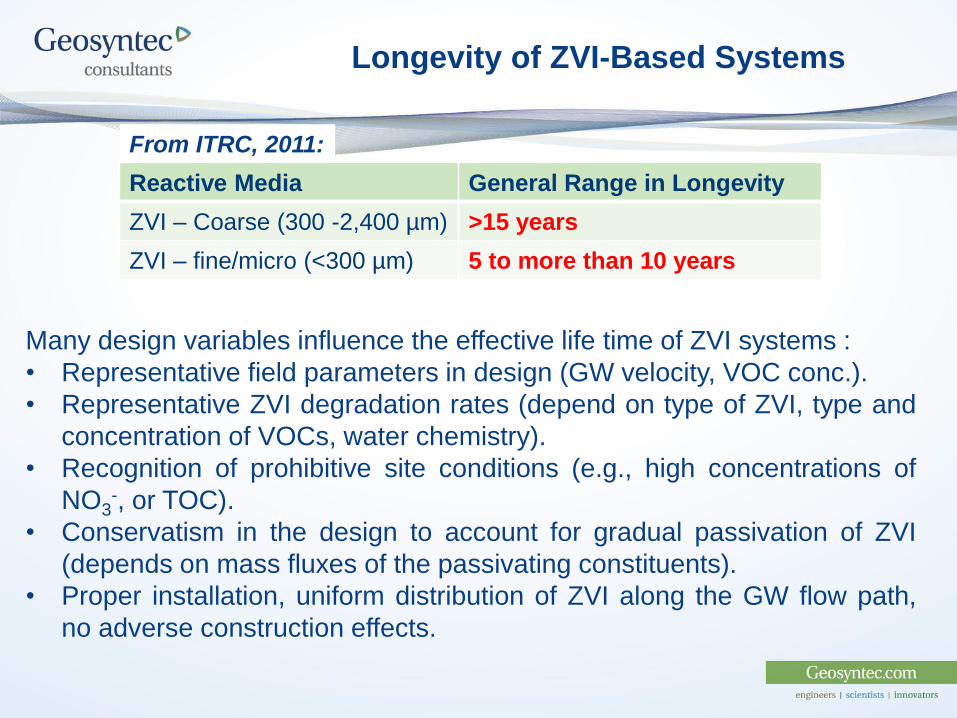
Longevity of ZVI-Based Systems
Many design variables influence the effective life time of ZVI systems :
• Representative field parameters in design (GW velocity, VOC conc.).
• Representative ZVI degradation rates (depend on type of ZVI, type and
concentration of VOCs, water chemistry).
• Recognition of prohibitive site conditions (e.g., high concentrations of
NO3-, or TOC).
• Conservatism in the design to account for gradual passivation of ZVI
(depends on mass fluxes of the passivating constituents).
• Proper installation, uniform distribution of ZVI along the GW flow path,
no adverse construction effects.
Reactive Media General Range in Longevity
ZVI – Coarse (300 -2,400 µm) >15 years
ZVI – fine/micro (<300 µm) 5 to more than 10 years
From ITRC, 2011: