Embed Size (px)
Citation preview

zero-riscy: User Manual January 2018 Revision 0.2
Pasquale Davide Schiavone ([email protected])
Micrel Lab and Multitherman Lab University of Bologna, Italy
Integrated Systems Lab ETH Zürich, Switzerland

ZERO-RISCY 15.01.2018
Rev. 0.2 Page 2 of 25
Copyright 2017 ETH Zurich and University of Bologna. Copyright and related rights are licensed under the Solderpad Hardware License, Version 0.51 (the “License”); you may not use this file except in compliance with the License. You may obtain a copy of the License at http://solderpad.org/licenses/SHL-0.51. Unless required by applicable law or agreed to in writing, software, hardware and materials distributed under this License is distributed on an “AS IS” BASIS, WITHOUT WARRANTIES OR CONDITIONS OF ANY KIND, either express or implied. See the License for the specific language governing permissions and limitations under the License.

ZERO-RISCY 15.01.2018
Rev. 0.2 Page 3 of 25
Document Revisions Rev. Date Author Description 0.1 06.06.17 P.D. Schiavone First Draft 0.2 15.01.18 P.D. Schiavone Fixed CSR reset values

ZERO-RISCY 15.01.2018
Rev. 0.2 Page 4 of 25
Table of Contents 1 Introduction....................................................................................................................................... 6
1.1 Supported Instruction Set ................................................................................................................. 6
1.2 ASIC Synthesis ................................................................................................................................ 6
1.3 FPGA Synthesis ............................................................................................................................... 6
1.4 Outline .............................................................................................................................................. 7
2 Instruction Fetch ............................................................................................................................... 8
2.1 Protocol ............................................................................................................................................ 8
3 Load-Store-Unit (LSU) ...................................................................................................................... 9
3.1 Misaligned Accesses ........................................................................................................................ 9
3.2 Protocol ............................................................................................................................................ 9
4 Register File ................................................................................................................................... 11
4.1 Latch-based Register File ............................................................................................................... 11
5 Control and Status Registers .......................................................................................................... 12
5.1 Machine Status (MSTATUS) .......................................................................................................... 12
5.2 Machine Trap-Vector Base Address (MTVEC) ............................................................................... 13
5.3 Machine Exception PC (MEPC) ..................................................................................................... 13
5.4 Machine Cause (MCAUSE) ............................................................................................................ 14
5.5 MHARTID ....................................................................................................................................... 14
6 Performance Counters ................................................................................................................... 15
6.1 Performance Counter Mode Register (PCMR) ............................................................................... 15
6.2 Performance Counter Event Register (PCER) ............................................................................... 15
6.3 Performance Counter Counter Register (PCCR0-31)..................................................................... 16
7 Exceptions and Interrupts ............................................................................................................... 19
7.1 Interrupts ........................................................................................................................................ 19
7.2 Exceptions ...................................................................................................................................... 19
7.3 Handling ......................................................................................................................................... 19
8 Debug Unit ..................................................................................................................................... 20
8.1 Address Map .................................................................................................................................. 20
8.2 Debug Registers ............................................................................................................................. 20 8.2.1 Debug Control (DBG_CTRL) ........................................................................................................................................ 21 8.2.2 Debug Hit (DBG_HIT) ................................................................................................................................................... 21 8.2.3 Debug Interrupt Enable (DBG_IE) ................................................................................................................................ 22 8.2.4 Debug Cause (DBG_CAUSE) ...................................................................................................................................... 23 8.2.5 Debug Hardware Breakpoint x Control (DBG_BPCTRLx) ............................................................................................ 23 8.2.6 Debug Next Program Counter (DBG_NPC) ................................................................................................................. 24 8.2.7 Debug Previous Program Counter (DBG_PPC) ........................................................................................................... 24

ZERO-RISCY 15.01.2018
Rev. 0.2 Page 5 of 25
8.3 Control and Status Registers .......................................................................................................... 25
8.4 Interface ......................................................................................................................................... 25

ZERO-RISCY 15.01.2018
Rev. 0.2 Page 6 of 25
1 Introduction ZERO-RISCY is a 2-stage in-order 32b RISC-V processor core. ZERO-RISCY has been designed to be small and efficient. Via two parameters, the core is configurable to support four ISA configurations. Figure 1 shows a block diagram of the core.
Figure 1: Block Diagram
1.1 Supported Instruction Set ZERO-RISCY supports the following instructions:
• Full support for RV32I Base Integer Instruction Set
• Full support for RV32E Base Integer Instruction Set
• Full support for RV32C Standard Extension for Compressed Instructions
• Full support for RV32M Integer Multiplication and Division Instruction Set Extension
The RV32M and RV32E can be enable and disable using two parameters.
1.2 ASIC Synthesis ASIC synthesis is supported for ZERO-RISCY. The whole design is completely synchronous and uses positive-edge triggered flip-flops, except for the register file, which can be implemented either with latches or with flip-flops. See Chapter 4 for more details about the register file. The core occupies an area of about 18.9 kGE when the latch based register file and the RV32IMC ISA is used or 11.6 kGE when the RV32EC is used .
1.3 FPGA Synthesis FPGA synthesis is supported for ZERO-RISCY when the flip-flop based register file is used. Since latches are not well supported on FPGAs, it is crucial to select the flip-flop based register file.

ZERO-RISCY 15.01.2018
Rev. 0.2 Page 7 of 25
1.4 Outline This document summarizes all the functionality of the ZERO-RISCY core in more detail. First, the instruction and data interfaces are explained in Chapter 2 and 3. Chapter 4 explains the register file. Control and status registers are explained in Chapter 5 and Chapter 6 gives an overview of all performance counters. Chapter 7 deals with exceptions and interrupts, and finally Chapter 8 summarizes the accessible debug registers.
ZERO-RISCY 15.01.2018
Rev. 0.2 Page 8 of 25
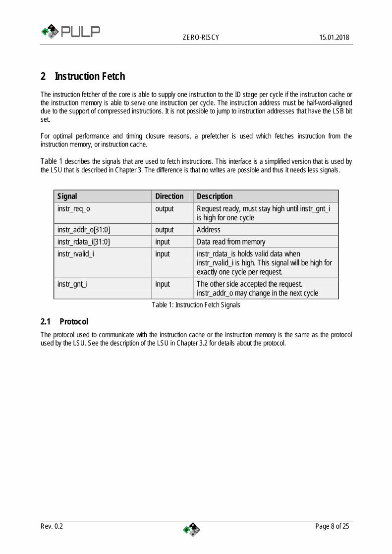
2 Instruction Fetch The instruction fetcher of the core is able to supply one instruction to the ID stage per cycle if the instruction cache or the instruction memory is able to serve one instruction per cycle. The instruction address must be half-word-aligned due to the support of compressed instructions. It is not possible to jump to instruction addresses that have the LSB bit set. For optimal performance and timing closure reasons, a prefetcher is used which fetches instruction from the instruction memory, or instruction cache. Table 1 describes the signals that are used to fetch instructions. This interface is a simplified version that is used by the LSU that is described in Chapter 3. The difference is that no writes are possible and thus it needs less signals.
Signal Direction Description instr_req_o output Request ready, must stay high until instr_gnt_i
is high for one cycle instr_addr_o[31:0] output Address instr_rdata_i[31:0] input Data read from memory instr_rvalid_i input instr_rdata_is holds valid data when
instr_rvalid_i is high. This signal will be high for exactly one cycle per request.
instr_gnt_i input The other side accepted the request. instr_addr_o may change in the next cycle
Table 1: Instruction Fetch Signals
2.1 Protocol The protocol used to communicate with the instruction cache or the instruction memory is the same as the protocol used by the LSU. See the description of the LSU in Chapter 3.2 for details about the protocol.

ZERO-RISCY 15.01.2018
Rev. 0.2 Page 9 of 25
3 Load-Store-Unit (LSU) The LSU of the core takes care of accessing the data memory. Load and stores on words (32 bit), half words (16 bit) and bytes (8 bit) are supported. Table 2 describes the signals that are used by the LSU.
Signal Direction Description data_req_o output Request ready, must stay high until data_gnt_i
is high for one cycle data_addr_o[31:0] output Address data_we_o output Write Enable, high for writes, low for reads.
Sent together with data_req_o data_be_o[3:0] output Byte Enable. Is set for the bytes to write/read,
sent together with data_req_o data_wdata_o[31:0] output Data to be written to memory, sent together with
data_req_o data_rdata_i[31:0] input Data read from memory data_rvalid_i input data_rdata_is holds valid data when
data_rvalid_i is high. This signal will be high for exactly one cycle per request.
data_gnt_i input The other side accepted the request. data_addr_o may change in the next cycle
Table 2: LSU Signals
3.1 Misaligned Accesses The LSU is able to perform misaligned accesses, meaning accesses that are not aligned on natural word boundaries. However, it needs to perform two separate word-aligned accesses internally. This means that at least two cycles are needed for misaligned loads and stores.
3.2 Protocol The protocol that is used by the LSU to communicate with a memory works as follows: The LSU provides a valid address in data_addr_o and sets data_req_o high. The memory then answers with a data_gnt_i set high as soon as it is ready to serve the request. This may happen in the same cycle as the request was sent or any number of cycles later. After a grant was received, the address may be changed in the next cycle by the LSU. In addition, the data_wdata_o, data_we_o and data_be_o signals may be changed as it is assumed that the memory has already processed and stored that information. After receiving a grant, the memory answers with a data_rvalid_i set high if data_rdata_i is valid. This may happen one or more cycles after the grant has been received. Note that data_rvalid_i must also be set when a write was performed, although the data_rdata_i has no meaning in this case. Figure 2, Figure 3 and Figure 4 show example-timing diagrams of the protocol.

ZERO-RISCY 15.01.2018
Rev. 0.2 Page 10 of 25
Figure 2: Basic Memory Transaction
Figure 3: Back-to-back Memory Transaction
Figure 4: Slow Response Memory Transaction

ZERO-RISCY 15.01.2018
Rev. 0.2 Page 11 of 25
4 Register File ZERO-RISCY has 31 or 15 32-bit wide registers depending if the RV32E extension is enabled. Register x0 is statically bound to 0 and can only be read, it does not contain any sequential logic. There are two flavors of register file available:
1. Latch-based 2. Flip-flop based
While the latch-based register file is recommended for ASICs, the flip-flop based register file is recommended for FPGA synthesis, although both are compatible with either synthesis target. Note the flip-flop based register file is significantly larger than the latch-based register-file for an ASIC implementation.
4.1 Latch-based Register File The latch based register file contains manually instantiated clock gating cells to keep the clock inactive when the latches are not written. It is assumed that there is a clock gating cell for the target technology that is wrapped in a module called cluster_clock_gating and has the following ports:
• clk_i: Clock Input • en_i: Clock Enable Input • test_en_i: Test Enable Input (activates the clock even though en_i is not set) • clk_o: Gated Clock Output

ZERO-RISCY 15.01.2018
Rev. 0.2 Page 12 of 25
5 Control and Status Registers ZERO-RISCY does not implement all control and status registers specified in the RISC-V privileged specifications, but is limited to the registers that were needed for the PULP system. The reason for this is that we wanted to keep the footprint of the core as low as possible and avoid any overhead that we do not explicitly need.
CSR Address Hex Name Acc. Description 11:10 9:8 7:6 5:0 00 11 00 000000 0x300 MSTATUS R/W Machine Status 00 11 00 000101 0x305 MTVEC R Machine Trap-Vector Base Address 00 11 01 000001 0x341 MEPC R/W Machine Exception Program Counter 00 11 01 000010 0x342 MCAUSE R/W Machine Trap Cause 01 11 00 0xxxxx 0x780-0x79F PCCRs R/W Performance Counter Counter Registers 01 11 10 100000 0x7A0 PCER R/W Performance Counter Enable 01 11 10 100001 0x7A1 PCMR R/W Performance Counter Mode 11 11 00 010100 0xF14 MHARTID R Hardware Thread ID
Table 3: Control and Status Register Map
5.1 Machine Status (MSTATUS) CSR Address: 0x300
Reset Value: 0x0000_1800 31 12 11 7 3
MPP
MPIE
MIE
Detailed: Bit # R/W Description 12:11 R MPP: Statically 2’b11 and cannot be altered (read-only). 7 R/W Previous Interrupt Enable: When an exception is encountered, MPIE will be set to IE.
When the mret instruction is executed, the value of MPIE will be stored to IE. 3 R/W Interrupt Enable: If you want to enable interrupt handling in your exception handler, set the
Interrupt Enable to 1’b1 inside your handler code.

ZERO-RISCY 15.01.2018
Rev. 0.2 Page 13 of 25
5.2 Machine Trap-Vector Base Address (MTVEC) CSR Address: 0x305 31 7 0
When an exception is encountered, the core jumps to the corresponding handler using the content of the MTVEC as base address. It is a read-only register which contains the boot address.
Table 3: MTVEC
5.3 Machine Exception PC (MEPC) CSR Address: 0x341
Reset Value: 0x0000_0000 31 0
MEPC
When an exception is encountered, the current program counter is saved in MEPC, and the core jumps to the exception address. When an mret instruction is executed, the value from MEPC replaces the current program counter.

ZERO-RISCY 15.01.2018
Rev. 0.2 Page 14 of 25
5.4 Machine Cause (MCAUSE) CSR Address: 0x342
Reset Value: 0x0000_0000 31 4 0
Interrupt
Exception Code
Detailed: Bit # R/W Description 31 R Interrupt: This bit is set when the exception was triggered by an interrupt. 4:0 R Exception Code
Table4: MCAUSE
5.5 MHARTID CSR Address: 0xF14
Reset Value: Defined 31 10 5 4 3 0
Cluster ID Core ID Detailed: Bit # R/W Description 10:5 R Cluster ID: ID of the cluster 3:0 R Core ID: ID of the core within the cluster
Table 5: MHARTID

ZERO-RISCY 15.01.2018
Rev. 0.2 Page 15 of 25
6 Performance Counters Performance Counters in ZERO-RISCY are placed inside the Control and Status Registers and can be accessed with csrr and csrw instructions. See Table 9.1 for the address map of the performance counter registers
6.1 Performance Counter Mode Register (PCMR) CSR Address: 0x7A1
Reset Value: 0x0000_0003 31 1 0
Saturation Global Enable
Detailed: Bit # R/W Description 1 R/W Global Enable: Activate/deactivate all performance counters. If this bit is 0, all
performance counters are disabled. After reset, this bit is set. 0 R/W Saturation: If this bit is set, saturating arithmetic is used in the performance counter
counters. After reset, this bit is set. Table 6: PCMR
6.2 Performance Counter Event Register (PCER) CSR Address: 0x7A0
Reset Value: 0x0000_0000 31 16 15 14 13 12 11 10 9 8 7 6 5 4 3 2 1 0
TCDM_CONT
ST_EXT_CYC
LD_EXT_CYC
ST_EXT
LD_EXT
DELAY_SLOT
BRANCH
JUMP
ST
LD
WBRANCH_CYC
WBRANCH
IMISS
- -
INSTR
CYCLES
Detailed: Bit # R/W Description 16 R/W TCDM_CONT 15 R/W ST_EXT_CYC 14 R/W LD_EXT_CYC

ZERO-RISCY 15.01.2018
Rev. 0.2 Page 16 of 25
Bit # R/W Description 13 R/W ST_EXT 12 R/W LD_EXT 11 R/W DELAY_SLOT 10 R/W BRANCH 9 R/W JUMP 8 R/W ST 7 R/W LD 6 R/W WBRANCH_CYC 5 R/W WBRANCH 4 R/W IMISS 3 R/W RESERVED 2 R/W RESERVED 1 R/W INSTR 0 R/W CYCLES
Table 7: PCER
Each bit in the PCER register controls one performance counter. If the bit is 1, the counter is enabled and starts counting events. If it is 0, the counter is disabled and its value won’t change. In the ASIC there is only one counter register, thus all counter events are masked by PCER and ORed together, i.e. if one of the enabled event happens, the counter will be increased. If multiple non-masked events happen at the same time, the counter will only be increased by one. In order to be able to count separate events on the ASIC, the program can be executed in a loop with different events configured. In the FPGA or RTL simulation version, each event has its own counter and can be accessed separately.
6.3 Performance Counter Counter Register (PCCR0-31) CSR Address: 0x780 - 0x79F
Reset Value: 0x0000_0000 31 0
Unsigned Integer Counter Value
Table 4: PCCR0-31
PCCR registers support both saturating and wrap-around arithmetic. This is controlled by the saturation bit in PCMR.

ZERO-RISCY 15.01.2018
Rev. 0.2 Page 17 of 25
Register Name Description PCCR0 CYCLES Counts the number of cycles the core was active (not
sleeping) PCCR1 INSTR Counts the number of instructions executed PCCR2 - Reserved PCCR3 - Reserved PCCR4 IMISS Cycles waiting for instruction fetches, i.e. number of
instructions wasted due to non-ideal caching PCCR5 LD Number of data memory loads executed.
Misaligned accesses are counted twice PCCR6 ST Number of data memory stores executed.
Misaligned accesses are counted twice PCCR7 JUMP Number of unconditional jumps (j, jal, jr, jalr) PCCR8 BRANCH Number of branches.
Counts taken and not taken branches PCCR9 BTAKEN Number of taken branches. PCCR10 RVC Number of compressed instructions executed PCCR11 LD_EXT Number of memory loads to EXT executed. Misaligned accesses
are counted twice. Every non-TCDM access is considered external (PULP only)
PCCR12 ST_EXT Number of memory stores to EXT executed. Misaligned accesses are counted twice. Every non-TCDM access is considered external (PULP only)
PCCR13 LD_EXT_CYC Cycles used for memory loads to EXT. Every non-TCDM access is considered external (PULP only)
PCCR14 ST_EXT_CYC Cycles used for memory stores to EXT. Every non-TCDM access is considered external (PULP only)
PCCR15 TCDM_CONT Cycles wasted due to TCDM/log-interconnect contention (PULP only)
PCCR31 ALL Special Register, a write to this register will set all counters to the supplied value
Table 8: PCCR Definitions
In the FPGA, RTL simulation and Virtual-Platform there are individual counters for each event type, i.e. PCCR0-30 each represent a separate register. To save area in the ASIC, there is only one counter and one counter register. Accessing PCCR0-30 will access the same counter register in the ASIC. Reading/writing from/to PCCR31 in the ASIC will access the same register as PCCR0-30. Figure 6 shows how events are first masked with the PCER register and then ORed together to increase the one performance counter PCCR.

ZERO-RISCY 15.01.2018
Rev. 0.2 Page 18 of 25
Figure 5: Events and PCCR, PCMR and PCER on the ASIC.

ZERO-RISCY 15.01.2018
Rev. 0.2 Page 19 of 25
7 Exceptions and Interrupts ZERO-RISCY supports interrupts, exceptions on illegal instructions.
Address Description 0x00-0x7C Interrupts 0 – 31 0x80 Reset 0x84 Illegal Instruction 0x88 ECALL Instruction Executed
Table 5: Interrupt/Exception Offset Vector Table
The base address of the interrupt vector table is given by the boot address. The most significant 3 bytes of the boot address given to the core are used for the first instruction fetch of the core and as the basis of the interrupt vector table. The core starts fetching at the address made by concatenating the most significant 3 bytes of the boot address and the reset value (0x80) as the least significant byte. The boot address can be changed after the first instruction was fetched to change the interrupt vector table address. It is assumed that the boot address is supplied via a register to avoid long paths to the instruction fetch unit.
7.1 Interrupts Interrupts can only be enabled/disabled on a global basis and not individually. It is assumed that there is an event/interrupt controller outside of the core that performs masking and buffering of the interrupt lines. The global interrupt enable is done via the CSR register MSTATUS. Multiple interrupts requests are assumed to be handled by event/interrupt controller. When an interrupt is taken, the core gives an acknowledge signal to the event/interrupt controller as well as the interrupt id taken.
7.2 Exceptions The illegal instruction exception and ecall instruction exceptions cannot be disabled and are always active.
7.3 Handling ZERO-RISCY does support nested interrupt/exception handling. Exceptions inside interrupt/exception handlers cause another exception, thus exceptions during the critical part of your exception handlers, i.e. before having saved the MEPC and MESTATUS registers, will cause those register to be overwritten. Interrupts during interrupt/exception handlers are disabled by default, but can be explicitly enabled if desired. Upon executing an mret instruction, the core jumps to the program counter saved in the CSR register MEPC and restores the MPIE value of the register MSTATUS to IE. When entering an interrupt/exception handler, the core sets MEPC to the current program counter and saves the current value of MIE in MPIE of the MSTATUS register.

ZERO-RISCY 15.01.2018
Rev. 0.2 Page 20 of 25
8 Debug Unit 8.1 Address Map
Address Name Description 0x0000-0x007F Debug Registers Always accessible, even when the core is running 0x400-0x47F GPR (x0-x31) General Purpose Registers
Only accessible if the core is halted 0x500-0x5FF FPR (f0-f31) Reserved. Not used in the ZERO-RISCY core.
First LSP from 0x500-0x57F, then MSP from 0x580-0x5FF
0x2000-0x20FF Debug Registers Only accessible if the core is halted 0x4000-0x7FFF CSR Control and Status Registers
Only accessible if the core is halted Table 9: Debug Unit Address Map
Addresses are intended for a bus system with 32-bit wide words. FPR get more address space than GPR because they can be 64-bit wide even in a 32-bit system. Addresses have to be aligned to word-boundaries.
8.2 Debug Registers
Address Name Description 0x00 DBG_CTRL Debug Control 0x04 DBG_HIT Debug Hit 0x08 DBG_IE Debug Interrupt Enable 0x0C DBG_CAUSE Debug Cause (Why we entered debug state) 0x40 DBG_BPCTRL0 HW BP0 Control 0x44 DBG_BPDATA0 HW BP0 Data 0x48 DBG_BPCTRL1 HW BP1 Control 0x4C DBG_BPDATA1 HW BP1 Data 0x50 DBG_BPCTRL2 HW BP2 Control 0x54 DBG_BPDATA2 HW BP2 Data 0x58 DBG_BPCTRL3 HW BP3 Control 0x5C DBG_BPDATA3 HW BP3 Data 0x60 DBG_BPCTRL4 HW BP4 Control

ZERO-RISCY 15.01.2018
Rev. 0.2 Page 21 of 25
Address Name Description 0x64 DBG_BPDATA4 HW BP4 Data 0x68 DBG_BPCTRL5 HW BP5 Control 0x6C DBG_BPDATA5 HW BP5 Data 0x70 DBG_BPCTRL6 HW BP6 Control 0x74 DBG_BPDATA6 HW BP6 Data 0x78 DBG_BPCTRL7 HW BP7 Control 0x7C DBG_BPDATA7 HW BP7 Data 0x2000 DBG_NPC Next PC 0x2004 DBG_PPC Previous PC
Table 10: Debug Unit Registers
8.2.1 Debug Control (DBG_CTRL) Compact:
31 30 29 28 27 26 25 24 23 22 21 20 19 18 17 16
reserved HALT R/W
15 14 13 12 11 10 9 8 7 6 5 4 3 2 1 0
reserved SSTE R/W
Detailed: Bit # R/W Description 16 W1 HALT: When 1 written, core enters debug mode, when 0 written, core exits debug
mode. When read, 1 means core is in debug modekkj
0 R/W SSTE: Single-step enable Table 11: DBG_CTRL register
8.2.2 Debug Hit (DBG_HIT) Compact:
31 30 29 28 27 26 25 24 23 22 21 20 19 18 17 16
reserved SLEEP R
15 14 13 12 11 10 9 8 7 6 5 4 3 2 1 0
reserved SSTH R/W

ZERO-RISCY 15.01.2018
Rev. 0.2 Page 22 of 25
Detailed: Bit # R/W Description 16 R SLEEP: Set when the core is in a sleeping state and waits for an event 0 R/W SSTH: Single-step hit, sticky bit that must be cleared by external debugger
Table 12: DBG_HIT register
8.2.3 Debug Interrupt Enable (DBG_IE) Compact:
31 30 29 28 27 26 25 24 23 22 21 20 19 18 17 16
TO BE DEFINED
15 14 13 12 11 10 9 8 7 6 5 4 3 2 1 0
reserved ECAL
L reserved SAF SAM LAF LAM BP ILL IAF IAM
R/W R/W R/W R/W R/W R/W R/W R/W R/W Detailed: Bit # R/W Description 11 R/W ECALL: Environment call from M-Mode 7 R/W SAF: Store Access Fault (together with LAF) 6 R/W SAM: Store Address Misaligned (never traps) 5 R/W LAF: Load Access Fault (together with SAF) 4 R/W LAM: Load Address Misaligned (never traps) 3 R/W BP: EBREAK instruction causes trap 2 R/W ILL: Illegal Instruction 1 R/W IAF: Instruction Access Fault (not implemented) 0 R/W IAM: Instruction Address Misaligned (never traps)
Table 13: DBG_IE register
When ‘1’ exceptions cause traps, otherwise normal exceptions.

ZERO-RISCY 15.01.2018
Rev. 0.2 Page 23 of 25
8.2.4 Debug Cause (DBG_CAUSE) Compact:
31 30 29 28 27 26 25 24 23 22 21 20 19 18 17 16 IRQ reserved R 15 14 13 12 11 10 9 8 7 6 5 4 3 2 1 0
reserved CAUSE R
Detailed: Bit # R/W Description 31 R IRQ: Interrupt caused us to enter debug mode 4:0 R CAUSE: Exception/interrupt number
Table 14: DBG_CAUSE register
8.2.5 Debug Hardware Breakpoint x Control (DBG_BPCTRLx) Compact:
31 30 29 28 27 26 25 24 23 22 21 20 19 18 17 16
reserved
15 14 13 12 11 10 9 8 7 6 5 4 3 2 1 0
reserved IMPL R0
Detailed: Bit # R/W Description 0 R IMPL: ZERO-RISCY does not implement hardware breakpoints. Always read as 0.
Table 15: DBG_BPCTRLx register

ZERO-RISCY 15.01.2018
Rev. 0.2 Page 24 of 25
8.2.6 Debug Next Program Counter (DBG_NPC) Compact:
31 30 29 28 27 26 25 24 23 22 21 20 19 18 17 16 NPC[31:16]
R/W 15 14 13 12 11 10 9 8 7 6 5 4 3 2 1 0
NPC[15:0] R/W
Detailed: Bit # R/W Description 31:0 R/W NPC: Next PC to be executed
Table 16: DBG_NPC register
When written core jumps to PC.
8.2.7 Debug Previous Program Counter (DBG_PPC) Compact:
31 30 29 28 27 26 25 24 23 22 21 20 19 18 17 16 PPC[31:16]
R 15 14 13 12 11 10 9 8 7 6 5 4 3 2 1 0
PPC[15:0] R
Detailed: Bit # R/W Description 31:0 W PPC: Previous PC, already executed
Table 17: DBG_PPC register
Values of PPC and NPC when entering debug mode:
Reason PPC NPC Cause GDB Sigval ebreak ebreak instruction next instruction BP TRAP ecall ecall instruction IVT entry ECALL TRAP illegal instruction illegal instruction IVT entry ILL ILL invalid mem access load/store instruction IVT entry LAF/SAF SEGV interrupt last instruction IVT entry ? INT

ZERO-RISCY 15.01.2018
Rev. 0.2 Page 25 of 25
Reason PPC NPC Cause GDB Sigval halt last instruction next instruction ? TRAP single-step last instruction next instruction ? TRAP
Table 18: NPC/PPC when entering Debug Mode
8.3 Control and Status Registers
Address Name Description 0x4000 CSR 0 = 0x000 CSR ... ... ... 0x7FFC CSR 4095 = 0xFFF CSR
Table 19: Debug CSR Mapping
Can only be accessed when core is in debug mode.
8.4 Interface
Signal Direction Description debug_req_i input Request debug_gnt_o output Grant debug_rvalid_o output Read data valid debug_addr_i[14:0] input Address for write/read debug_we_i input Write Enable debug_wdata_i[31:0] input Write data debug_rdata_o[31:0] output Read data debug_halted_o output Is high when core is in debug mode debug_halt_i input Set high when core should enter debug mode debug_resume_i input Set high when core should exit debug mode
Table 20: Debug Interface
debug_halted_o, debug_halt_i and debug_resume_i are intended for cross-triggering between multiple cores. They are not required for single-core debug, thus debug_halt_i and debug-resume_i can be tied to 0.
debug_halt_i and debug_resume_i should be high for only one single cycle to avoid deadlock issues.