Embed Size (px)
Citation preview

1
Zero Point System (ZPS) Installation of K5.3, K10.3 & K20.3
Low-Pressure Pneumatic Clamping Modules
For Jergens Part Numbers: 560601, 511139 & 511154
2
GENERAL INSTRUCTIONS 0. INTRODUCTION................................................................................................................... 3
0.1 Operating Personnel ....................................................................................................... 4 0.2 Trained Personnel ........................................................................................................... 5 0.3 Individual Protective Equipment ...................................................................................... 5 0.4 General Safety Instructions ............................................................................................. 5 0.5 Behavior in Case of Emergency ...................................................................................... 6 0.6 Restrictions on Usage ..................................................................................................... 6 0.7 Type Plates ..................................................................................................................... 7
1.0 TRANSPORT ....................................................................................................................... 7 2.0 DESCRIPTION OF THE SYSTEM ........................................................................................ 8
2.1 Structure of the Zero Point System (ZPS) ....................................................................... 9 2.2 Circuit Diagram of the Zero Point System (ZPS) ............................................................. 9 2.3 Operation of the Zero Point System (ZPS) ...................................................................... 9
3.0 INSTALLATION .................................................................................................................. 11 3.1- General ........................................................................................................................ 11 3.2 Installation in a Mounting Hole ...................................................................................... 11 3.3 Installation Clamping Modules with Indexing ................................................................. 13 3.4 Removal from a Mounting Hole ..................................................................................... 13
4.0 PULL STUDS ..................................................................................................................... 14 4.1 Design ........................................................................................................................... 14 4.2 Installation Instructions .................................................................................................. 14 4.3 Tolerances and Pull Studs Arrangement ....................................................................... 15
5.0 PERFORMANCE AND RESTRICTIONS ON USE ............................................................. 16 5.1 Pull-in and Looking Force .............................................................................................. 16 5.2 Holding Force ................................................................................................................ 16 5.3 Safety Precautions ........................................................................................................ 16
6.0 MAINTENANCE ................................................................................................................. 17 6.1 Introduction ................................................................................................................... 17 6.2 Safety Standards During Maintenance .......................................................................... 17 6.3 Daily Maintenance ......................................................................................................... 17 6.4 Monthly Maintenance .................................................................................................... 18 6.5 Maintenance ................................................................................................................. 18
7.0 POSSIBLE PROBLEMS AND HOW TO REMEDY THEM.................................................. 18 8.0 DECOMMISSIONING AND DISPOSAL.............................................................................. 19
8.1 Decommissioning .......................................................................................................... 19 8.2 Placing into Storage ...................................................................................................... 19 8.3 Disposal ........................................................................................................................ 19
3
GENERAL INSTRUCTIONS
This installation manual will assist you in becoming familiar with your new product. For that reason, we recommend that you read the documentation carefully and follow all instructions. If you require additional information, we would ask you to contact our Technical Service at 877-426-2504. THIS MANUAL
Please consider this installation manual an important component of the delivered system. It should be well taken care of during the entire time the system is in use. A copy of this installation manual must be made available to the installation, operating and maintenance personnel. Please ensure that all additional documents delivered are integrated into this manual. If your system is transferred to a third party, we request that you also pass on this manual. STORAGE OF THE MANUAL
Always treat this manual with care. You must not tear out pages or make modifications. Please keep these documents protected from heat and humidity. Jergens Inc. reserves the right to replace parts of the instructions contained herein at any time in the course of product improvement, or if construction or commercial changes so demand, without immediately providing a new edition. As the author of this manual, Jergens Inc. forbids reproduction of this manual in whole or in part as well as making it available to third parties without written permission. Any modification of the product requires the manufacturer's consent. 0. INTRODUCTION
1. CAUTION: The original configuration of this system may not be modified under any conditions. Using this system for purposes other than those which the manufacturer intended can damage the system or harm the operator. The manufacturer's consent must be obtained before working on materials other than those described in these instructions.

4
Symbols used:
Machining processes that represent a risk or can cause injuries or harm to health if they are not
properly performed.
Machining processes that may only be performed by qualified specialist personnel. The
possibility of residual risks cannot be ruled out.
0.1 Operating personnel As already mentioned above, certain operations must be performed exclusively by qualified or
trained personnel. The following characteristics are used to describe the qualification level:
Qualified personnel have sufficient technical knowledge or work experience to be able to
recognize and prevent possible dangers (engineers and technicians).
Trained personnel are appropriately instructed and/or monitored by qualified persons to be
able to recognize the dangers and prevent them (personnel assigned to operation or
maintenance).
They must have the following qualifications:
1. They must be trained and authorized to operate the product safely and supply it with
operating pressure or interrupt the supply and mark it in accordance with the standard
safety regulations.
2. They must be trained in the correct procedure for maintenance and use of safety
equipment in accordance with the standard safety regulations.
Before commissioning the equipment, the customer is obligated to make sure:
1. Personnel have obtained, read and understood the installation manual;
2. Personnel follow the instructions provided.
5
0.2 Trained personnel
MACHINE OPERATORS: One or more persons who, based on appropriate instructions from the
owner of the Zero Point System (ZPS), are assigned and authorized to operate it and connected
devices. Another prerequisite is the complete knowledge and unrestricted understanding of the
contents of this manual.
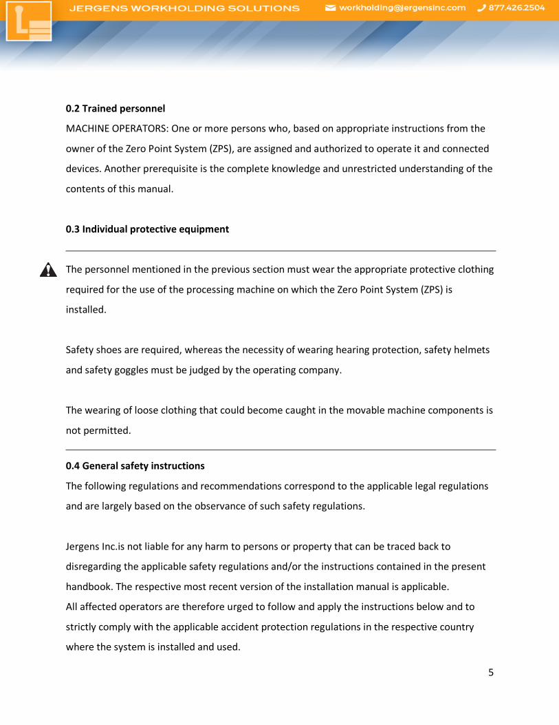
0.3 Individual protective equipment
The personnel mentioned in the previous section must wear the appropriate protective clothing
required for the use of the processing machine on which the Zero Point System (ZPS) is
installed.
Safety shoes are required, whereas the necessity of wearing hearing protection, safety helmets
and safety goggles must be judged by the operating company.
The wearing of loose clothing that could become caught in the movable machine components is
not permitted.
0.4 General safety instructions
The following regulations and recommendations correspond to the applicable legal regulations
and are largely based on the observance of such safety regulations.
Jergens Inc.is not liable for any harm to persons or property that can be traced back to
disregarding the applicable safety regulations and/or the instructions contained in the present
handbook. The respective most recent version of the installation manual is applicable.
All affected operators are therefore urged to follow and apply the instructions below and to
strictly comply with the applicable accident protection regulations in the respective country
where the system is installed and used.

6
All ordinary and extraordinary maintenance steps must be undertaken with the pressure supply
cut off. Before connecting the pressure, check whether the operating pressure is in accordance
with the maximum allowable operating pressure.
Transportation, installation, operation and ordinary or extraordinary maintenance of the Zero
Point System may be undertaken only by personnel meeting the requirements stated in
sections 0.1 and 0.2.
0.5 Behavior in case of emergency
In emergencies, it is recommended that the procedures from the operating and maintenance
instructions of the machine on which the Zero Point System is installed should be followed in
emergencies.
In particular, measures must be taken so that no danger to persons or property can arise in
case of a defect. In case of fire, take the designated extinguishing measures and take care that
operating pressure is no longer present.
0.6 Restrictions on usage
The Zero Point system (ZPS) may be used solely for the uses specified in the installation manual,
and only in combination with the components recommended and approved by Jergens Inc.
Allowed usage of the Zero Point System (ZPS): The ZPS is a spring- actuated single-acting
clamping element that clamps a clamping plate or a workpiece pressure-free and self-locked
with the Jergens Inc. pull stud. It is intended for installation on or in machines or systems, and
may be used only within the scope of its technical data. The maximum loads and operating
pressures specified by the manufacturer must not be exceeded. All other types of use must be
approved by the manufacturer.

7
0.7 Type plates
A label or the type plate of the manufacturer is affixed to the Zero Point System.
CAUTION:
Labels must not be removed under any conditions, even if the equipment is to be resold.
Should the label be damaged or become detached, please contact Jergens Inc.to obtain a copy.
In all communications with Jergens Inc. please always mention the model on the label.
Disregarding these provisions releases Jergens Inc. from any liability for damage or accidents
caused thereby. In this case, the operating company is solely liable to the authorities.
1. TRANSPORT
Every Zero Point System (ZPS) is carefully tested before shipping. Upon receipt of the product,
please check the integrity of the packaging and contents (subject to other instructions on the
part of Jergens Inc. to ensure that the equipment was not damaged during transport and that
the delivery corresponds to the specification of the order, please report any defects or damage
immediately to Jergens Inc. and the shipper who is liable for the transport damage.
CAUTION:
Any defects or damage must be claimed within 10 days of the receipt of
the product.
8
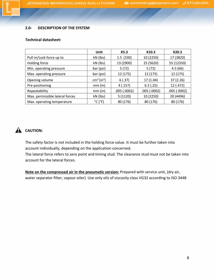
2.0- DESCRIPTION OF THE SYSTEM Technical datasheet:
Unit K5.3 K10.3 K20.3 Pull-in/Lock force up to kN (lbs) 1.5 (330) 10 (2250) 17 (3820) Holding force kN (lbs) 13 (2900) 25 (5620) 55 (12350) Min. operating pressure bar (psi) 5 (72) 5 (72) 4.5 (66) Max. operating pressure bar (psi) 12 (175) 12 (175) 12 (175)
Opening volume cm3 (in3) 6 (.37) 17 (1.04) 37 (2.26) Pre-positioning mm (in) 4 (.157) 6.5 (.25) 12 (.472) Repeatability mm (in) .005 (.0002) .005 (.0002) .005 (.0002) Max. permissible lateral forces kN (lbs) 5 (1120) 10 (2250) 20 (4496) Max. operating temperature °C (°F) 80 (176) 80 (176) 80 (176)
CAUTION: The safety factor is not included in the holding force value. It must be further taken into account individually, depending on the application concerned. The lateral force refers to zero point and timing stud. The clearance stud must not be taken into account for the lateral forces. Note on the compressed air in the pneumatic version: Prepared with service unit, (dry air, water separator filter, vapour oiler). Use only oils of viscosity class VG32 according to ISO 3448

9
2.1 Structure of the Zero Point System (ZPS)
1. Ball 2. Mounting screw 3. Threaded pin as forcing screw (not shown in the drawing) 4. Threaded stud 5. Installation tool pre-mounted
2.2 Circuit diagram of the Zero Point System (ZPS) Description of the required connections:
1 = Open pneumatically 3 = Blow-out pneumatically (optional)
2.3. Operation of the Zero Point System (ZPS) Opening procedure: Pressurize ZPS.
The ZPS will release the clamping nipple, enabling it to be moved in and out of the
system. The ZPS will re- main open as long as pressure is applied to the Open
connection.

10
Clamping procedure:
Depressurize ZPS.
The ZPS locks positively and is mechanically clamped by spring force. The ZPS will
remain closed as long as no pressure is applied to the Open connection.
Pressure line can be decoupled after the clamping process the ZPS remains
positively locked.
Integrated blow-out procedure
An air blast escapes from the ZPS center serves to clean the interior and top surface. During operation, there is danger of eye injury, since shavings can arise from the automatic blow out. CAUTION:
Wear safety goggles
Manual blow-out: The interior of the ZPS can be blown out with an ordinary commercial compressed air blow gun or suctioned out with a vacuum device. During operation, there is danger of eye injury, since shavings can arise from the blow- out. CAUTION:
Wear safety goggles
11
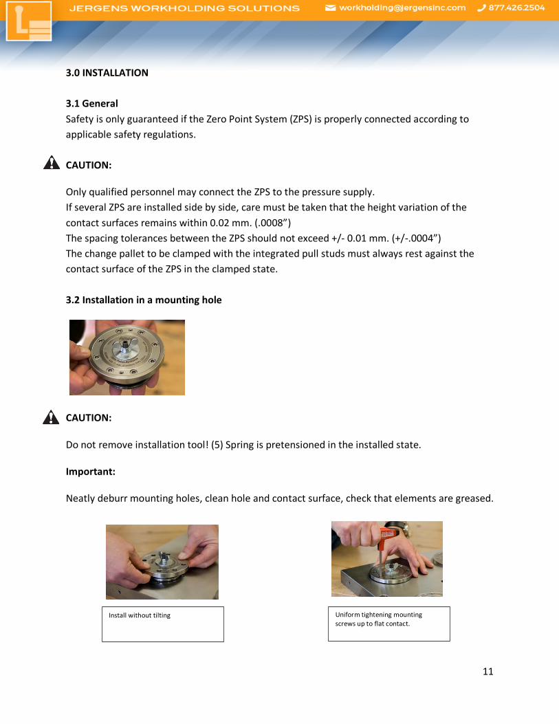
3.0 INSTALLATION 3.1 General Safety is only guaranteed if the Zero Point System (ZPS) is properly connected according to applicable safety regulations. CAUTION:
Only qualified personnel may connect the ZPS to the pressure supply. If several ZPS are installed side by side, care must be taken that the height variation of the contact surfaces remains within 0.02 mm. (.0008”) The spacing tolerances between the ZPS should not exceed +/- 0.01 mm. (+/-.0004”) The change pallet to be clamped with the integrated pull studs must always rest against the contact surface of the ZPS in the clamped state. 3.2 Installation in a mounting hole
CAUTION:
Do not remove installation tool! (5) Spring is pretensioned in the installed state.
Important:
Neatly deburr mounting holes, clean hole and contact surface, check that elements are greased.
Uniform tightening mounting screws up to flat contact.
Install without tilting
12
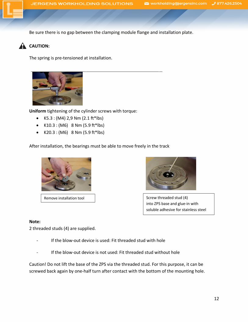
Be sure there is no gap between the clamping module flange and installation plate. CAUTION:
The spring is pre-tensioned at installation.
Uniform tightening of the cylinder screws with torque:
• K5.3 : (M4) 2,9 Nm (2.1 ft*lbs) • K10.3 : (M6) 8 Nm (5.9 ft*lbs) • K20.3 : (M6) 8 Nm (5.9 ft*lbs)
After installation, the bearings must be able to move freely in the track
Note: 2 threaded studs (4) are supplied.
- If the blow-out device is used: Fit threaded stud with hole
- If the blow-out device is not used: Fit threaded stud without hole
Caution! Do not lift the base of the ZPS via the threaded stud. For this purpose, it can be screwed back again by one-half turn after contact with the bottom of the mounting hole.
Remove installation tool Screw threaded stud (4) into ZPS base and glue-in with soluble adhesive for stainless steel

13
3.3 Installation clamping modules with indexing Orientation to the base plate of the indexing grooves in the cover of the installation clamping module is defined through 2 dowel pins ISO 8734– 6 or ISO 8735 – 6 (see installation sketch). Max. torque:
- K10.3 = 350Nm (250 ft*lbs) - K20.3 = 400Nm (295 ft*lbs)
Keys installed in the removable plate serve as orientation and power transmission. 3.4 Removal from a mounting hole
CAUTION: The ZPS must be completely depressurized before starting to dismantle.
Remove threaded stud (4) Insert installation tool (5)
Uniformly loosen cylinder screws (2)
Screw in threaded pins (3) in order to be able to press down the clamping system
Uniform and tilt-free removal of the clamping system
14
CAUTION: Spring is pre-tensioned in the installed state! Note on installation tool (5): Install a long screw with a large washer that covers the central
hole for the clamping stud into the base of the ZPS. This allows the ZPS to be held together
before removal so that it can be taken out as a unit.
The supply holes for the pressure medium must be free during removal, as otherwise a vacuum
could arise in the mounting hole.
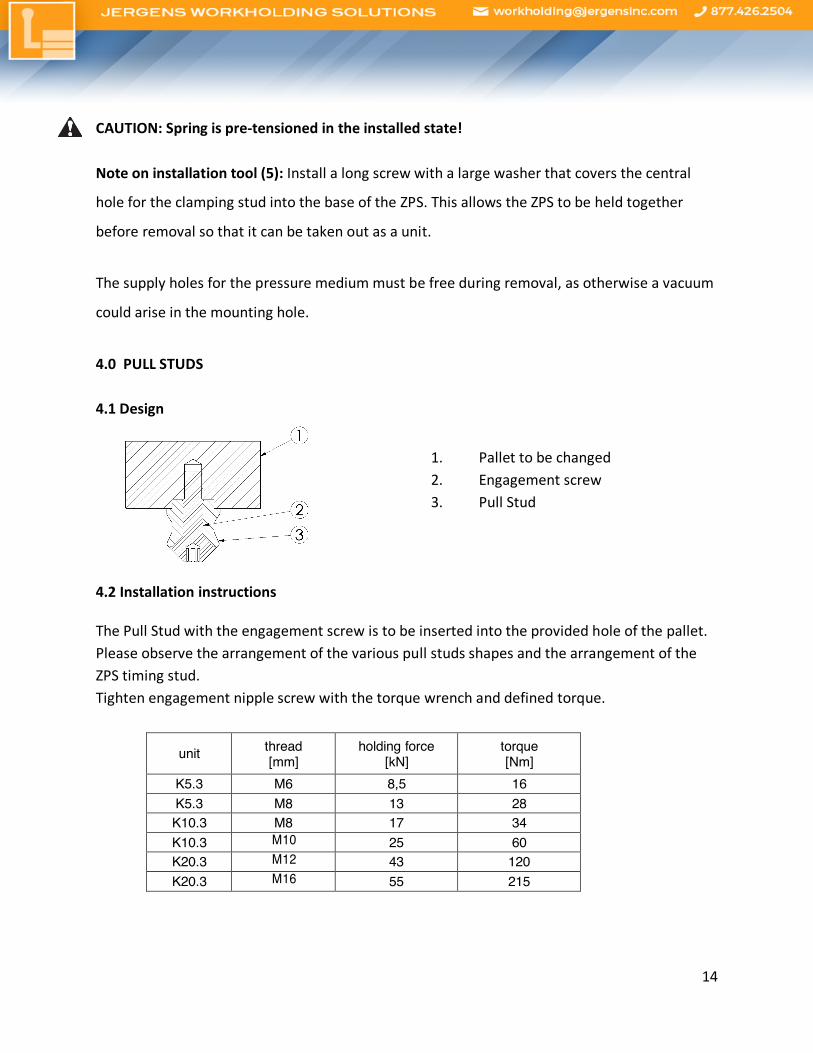
4.0 PULL STUDS 4.1 Design
1. Pallet to be changed 2. Engagement screw 3. Pull Stud
4.2 Installation instructions
The Pull Stud with the engagement screw is to be inserted into the provided hole of the pallet. Please observe the arrangement of the various pull studs shapes and the arrangement of the ZPS timing stud. Tighten engagement nipple screw with the torque wrench and defined torque.
unit thread [mm]
holding force [kN]
torque [Nm]
K5.3 M6 8,5 16 K5.3 M8 13 28 K10.3 M8 17 34 K10.3 M10 25 60 K20.3 M12 43 120 K20.3 M16 55 215

15
4.3 Tolerances and pull stud arrangement The clamping nipples have the following designs:
Zero-point stud (1) -for full centering
Timing Stud (2) -for centering the remaining free axis
Clearance Stud (3) – exclusively for holding and clamping function
Bottom view of a change pallet with representation of the arrangement of the various pull studs (drawing simplified):
Note: The raised sections of the timing stud diameter must lie at an angle of 90° to the axis of connection between itself and the zero-point nipple.

16
Distance tolerance: A = Zero-point to timing stud +/- 0.01mm (+/- .0004) B = Zero-point/timing stud to undersize clearance stud: +/- 0.03mm (+/- .0012) 5.0 PERFORMANCE AND RESTRICTIONS ON USE 5.1 Pull-in and locking force The pull-in and locking force describes the force with which the nipple is pulled in and clamped with positive locking in the clamping module. 5.2 Holding force The holding force specifies the maximum permissible axial pull force of the engagement nipple screw. A safety value suitable for the application must additionally be taken into consideration. Elevated tensile forces can cause a material-induced elastic deformation of the components. 5.3 Safety precautions Safety catch: An additional mechanical safety catch must be attached for vertically and horizontally suspended clamping. For this usage, the user must consider a risk analysis of the forces occurring and then carry out an accident risk assessment in order to take appropriate protective measures. People are not permitted to be present in the danger zone. Rotating applications: For rotary clamping, piston location sensing and contact monitoring are mandatory for safety reasons. For rotary usage, the user must consider a risk analysis of the shearing, centrifugal and imbalance forces occurring and then carry out an accident risk assessment in order to take appropriate protective measures. People are not permitted to be present in the danger zone.
17
6.0 MAINTENANCE 6.1 Introduction
Appropriate maintenance is important for a long service life of the system and its components
and additionally guarantees the required operating safety over the long term.
6.2 Safety standards during maintenance
CAUTION:
All maintenance steps must be undertaken by qualified personnel (see chapter 0.1).
Here are the most important points for the performance of maintenance measures:
• Maintenance and repair measures must be undertaken with a depressurized system.
The entire operating, maintenance and cleaning personnel must also strictly observe the
applicable accident prevention regulations in the country where the machine is
installed.
• The ZPS is constantly under high spring pressure. Due to pre- tensioning of the spring
stack, serious, even life-threatening injuries can result if maintenance is improper.
• Always wear safety shoes, glasses and all other required individual safety gear as well as
clothing that covers the body as completely as possible.
• Do not wear any rings, watches, necklaces, bracelets or loose clothing.
• To guarantee proper functioning, use only original replacement parts.
• Do not use abrasive or corrosive materials for cleaning the ZPS as they may reduce the
legibility of the markings or type plates.
6.3 Daily maintenance
Check the interior of the ZPS for contamination. It can be cleaned with an ordinary commercial
compressed air gun (wear safety goggles) or with a chip vacuum.
18
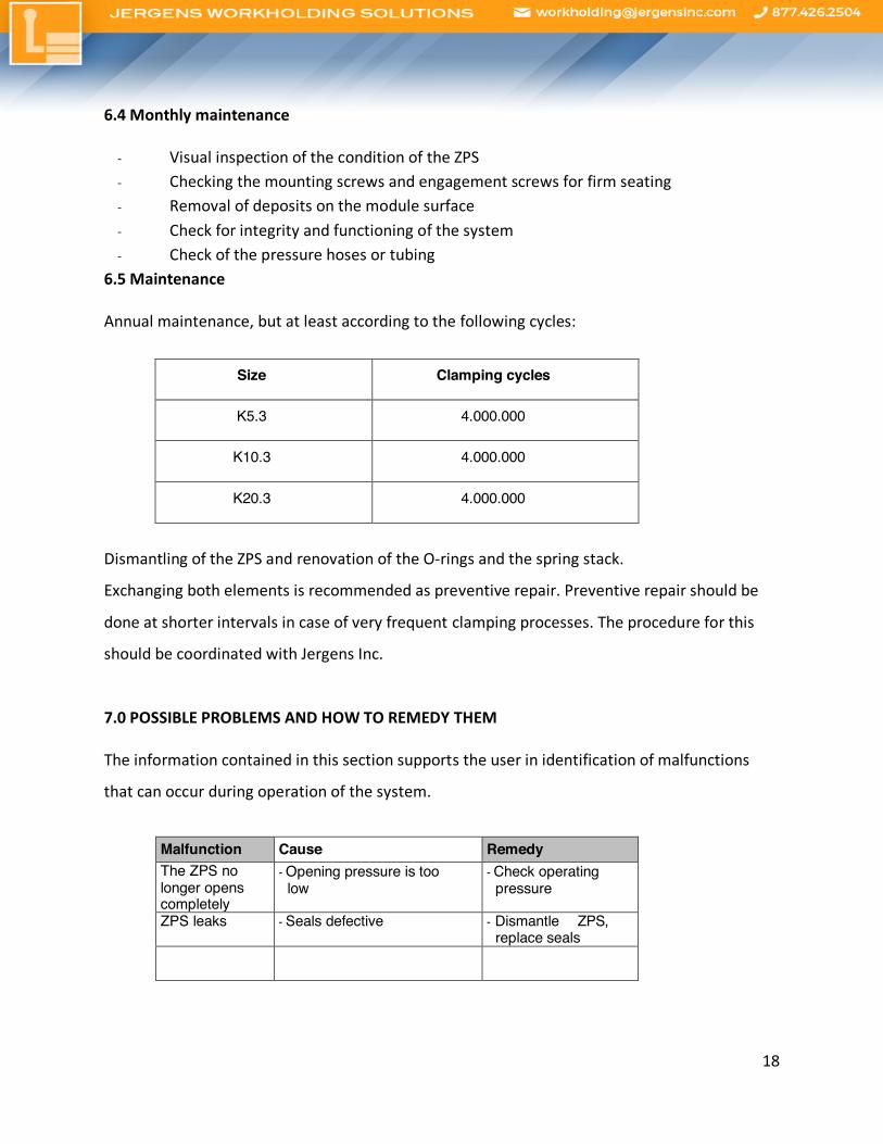
6.4 Monthly maintenance
- Visual inspection of the condition of the ZPS - Checking the mounting screws and engagement screws for firm seating - Removal of deposits on the module surface - Check for integrity and functioning of the system - Check of the pressure hoses or tubing
6.5 Maintenance
Annual maintenance, but at least according to the following cycles:
Size Clamping cycles
K5.3 4.000.000
K10.3 4.000.000
K20.3 4.000.000
Dismantling of the ZPS and renovation of the O-rings and the spring stack.
Exchanging both elements is recommended as preventive repair. Preventive repair should be
done at shorter intervals in case of very frequent clamping processes. The procedure for this
should be coordinated with Jergens Inc.
7.0 POSSIBLE PROBLEMS AND HOW TO REMEDY THEM
The information contained in this section supports the user in identification of malfunctions
that can occur during operation of the system.
Malfunction Cause Remedy The ZPS no longer opens completely
- Opening pressure is too low
- Check operating pressure
ZPS leaks - Seals defective - Dismantle ZPS, replace seals

19
8.0 DECOMMISSIONING AND DISPOSAL
8.1 Decommissioning
If the equipment is no longer going to be used, cut off the system from the pressure supply and
remove it from the production machine on which it is installed.
8.2 Placing into storage
The following points should be considered:
Clean and grease the surface of the Zero Point System.
Keep the system in a dry environment at +10℃ (32°F) 55°C (131°F).
8.3 Disposal
If the ZPS is to be scrapped, the oil in it must be emptied and disposed of in accordance with
the applicable legal regulations in the respective country.
The remaining parts of the system should be sorted by material and then also disposed of in
accordance with the legal regulations.
Jergens USA 15700 S. Waterloo Rd Cleveland, OH 44110 TELEPHONE: 216-486-5540 Fax: 216-481-6193 E-MAIL: [email protected] INTERNET: http://www.jergensinc.com/