Embed Size (px)
Citation preview
t
Zero-birefringence polymer by the anisotropicmolecule dope method
Akihiro Tagaya, Shuichi Iwata, Eriko Kawanami, Hisashi Tsukahara, andYasuhiro Koike
We propose using the anisotropic molecule dope method for synthesizing a zero-birefringence polymerthat showed no orientational birefringence at any orientation degree of polymer chains. In this methoda rodlike molecule with polarizability anisotropy was chosen to compensate orientational birefringence.The zero-birefringence polymer was synthesized by doping of 3-wt.% trans-stilbene as an anisotropicmolecule into poly~methyl methacrylate!. The zero-birefringence at the 590-nm wavelength in thedrawn film and the injection-molded plate made from the zero-birefringence polymer was confirmed bythe rotating parallel nicols method. Furthermore, high transparency ~37.2 dBykm! of the zero-birefringence polymer at the 633-nm wavelength was confirmed by the light-scattering measurement.© 2001 Optical Society of America
OCIS codes: 160.4670, 160.4760, 160.5470, 230.5440.
i
1. Introduction
Optical polymers have been widely used as key ma-terials for a variety of optical devices in recent opticaltechnology, for example, polymer optical fibers,1,2 op-ical films for liquid-crystal displays, optical disks,3
lenses,4 and so on, because of its easy processing, easyhandling, light weight, high transparency, and lowcost. Although most polymers are composed of theanisotropic monomers in terms of polarizability, theyexhibit no birefringence in perfectly amorphous state.However, the optical polymers tend to exhibit bire-fringence caused by orientation of polymer chains inthe process of injection molding or extrusion, whichrestricts their application to optical devices for han-dling polarized light. Optical polymers that exhibitno birefringence with any orientation of polymerchains are desirable for realizing high-performanceoptical devices for handling polarized light comparedwith conventional ones at small cost. We definesuch polymers as zero-birefringence polymers in thispaper.
The polymer blend method was a well-known
The authors are with the Faculty of Science and Technology,Keio University, 3-14-1, Hiyoshi, Kohoku-ku, Yokohama 223-8522,Japan. A. Tagaya’s e-mail address is [email protected].
Received 11 September 2000; revised manuscript received 24April 2001.
0003-6935y01y223677-07$15.00y0© 2001 Optical Society of America
method for realizing the zero-birefringence polymer,in which negative and positive birefringence ho-mopolymers were blended.5,6 However, it is, in gen-eral, difficult to completely blend two polymers in theprocess of injection molding or extrusion so that theyhave sufficient transparency and homogeneity re-quired for use as high-performance optical devices,because they tend to cause phase separation of theorder of more than several hundred angstroms lead-ing to scattering. Iwata et al. proposed using therandom copolymerization method to solve the prob-lem of the polymer blend method, in which negativeand positive birefringence monomers randomly copo-lymerized.7,8 In fact, they realized some types ofzero-birefringence polymers with sufficient transpar-ency for some optical devices such as pick-up lensesfor optical disks by use of the random copolymeri-zation method. However, the choices of negativeand positive birefringence monomers for randomcopolymerization are limited. Furthermore, typicaloptical and mechanical properties of most zero-birefringence polymers synthesized by the two meth-ods mentioned above were significantly differentfrom those of corresponding homopolymers, becausethe mixing ratio of other polymers or monomerswas usually more than 10 wt.%. Therefore withthese methods it is difficult to compensate the bire-fringence of the conventional optical polymers suchas poly~methyl methacrylate! ~PMMA! while preserv-ng their optical and mechanical properties.
Our purpose in this paper is to propose using the
1 August 2001 y Vol. 40, No. 22 y APPLIED OPTICS 3677
itm
H
cv
3
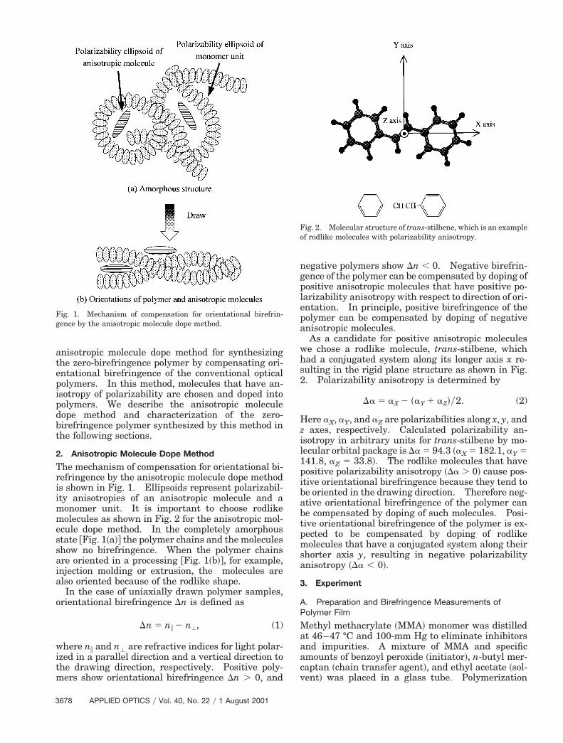
anisotropic molecule dope method for synthesizingthe zero-birefringence polymer by compensating ori-entational birefringence of the conventional opticalpolymers. In this method, molecules that have an-isotropy of polarizability are chosen and doped intopolymers. We describe the anisotropic moleculedope method and characterization of the zero-birefringence polymer synthesized by this method inthe following sections.
2. Anisotropic Molecule Dope Method
The mechanism of compensation for orientational bi-refringence by the anisotropic molecule dope methodis shown in Fig. 1. Ellipsoids represent polarizabil-ity anisotropies of an anisotropic molecule and amonomer unit. It is important to choose rodlikemolecules as shown in Fig. 2 for the anisotropic mol-ecule dope method. In the completely amorphousstate @Fig. 1~a!# the polymer chains and the moleculesshow no birefringence. When the polymer chainsare oriented in a processing @Fig. 1~b!#, for example,injection molding or extrusion, the molecules arealso oriented because of the rodlike shape.
In the case of uniaxially drawn polymer samples,orientational birefringence Dn is defined as
Dn 5 ni 2 n', (1)
where ni and n' are refractive indices for light polar-zed in a parallel direction and a vertical direction tohe drawing direction, respectively. Positive poly-ers show orientational birefringence Dn . 0, and
Fig. 1. Mechanism of compensation for orientational birefrin-gence by the anisotropic molecule dope method.
678 APPLIED OPTICS y Vol. 40, No. 22 y 1 August 2001
negative polymers show Dn , 0. Negative birefrin-gence of the polymer can be compensated by doping ofpositive anisotropic molecules that have positive po-larizability anisotropy with respect to direction of ori-entation. In principle, positive birefringence of thepolymer can be compensated by doping of negativeanisotropic molecules.
As a candidate for positive anisotropic moleculeswe chose a rodlike molecule, trans-stilbene, whichhad a conjugated system along its longer axis x re-sulting in the rigid plane structure as shown in Fig.2. Polarizability anisotropy is determined by
Da 5 aX 2 ~aY 1 aZ!y2. (2)
ere aX, aY, and aZ are polarizabilities along x, y, andz axes, respectively. Calculated polarizability an-isotropy in arbitrary units for trans-stilbene by mo-lecular orbital package is Da 5 94.3 ~aX 5 182.1, aY 5141.8, aZ 5 33.8!. The rodlike molecules that havepositive polarizability anisotropy ~Da . 0! cause pos-itive orientational birefringence because they tend tobe oriented in the drawing direction. Therefore neg-ative orientational birefringence of the polymer canbe compensated by doping of such molecules. Posi-tive orientational birefringence of the polymer is ex-pected to be compensated by doping of rodlikemolecules that have a conjugated system along theirshorter axis y, resulting in negative polarizabilityanisotropy ~Da , 0!.
3. Experiment
A. Preparation and Birefringence Measurements ofPolymer Film
Methyl methacrylate ~MMA! monomer was distilledat 46–47 °C and 100-mm Hg to eliminate inhibitorsand impurities. A mixture of MMA and specificamounts of benzoyl peroxide ~initiator!, n-butyl mer-aptan ~chain transfer agent!, and ethyl acetate ~sol-ent! was placed in a glass tube. Polymerization
Fig. 2. Molecular structure of trans-stilbene, which is an exampleof rodlike molecules with polarizability anisotropy.
s
m;sprb1BltpwKslmi
awt
apoPtmpl
dpt
waf
Table 1. Conditions of the Injection Molding
was carried out with the glass tube immersed in wa-ter at 70 °C. After polymerization, the polymer solu-tion was filtered through a 0.2-mm-membrane filterand dropped into methanol to precipitate the polymerand remove remaining monomers. The obtainedpolymer was dried under reduced pressure for 48 h,and then it was dissolved in ethyl acetate with trans-stilbene. The polymer solution was cast onto a glassplate to prepare film samples with a knife coater.The polymer film was dried at 110 °C at a loweredpressure ~,0.01-mm Hg! for 3 days to eliminate theolvent.The dried polymer film including the anisotropicolecules was uniaxially heat drawn at a rate of0.11 mmys in hot silicone oil. PMMA and trans-
tilbene-doped PMMA films with a thickness of ap-roximately 30 mm were heat drawn at 90 and 70 °C,espectively. The drawing temperatures were setelow their glass transition temperature ~Tg; PMMA,00 °C; 3-wt.% trans-stilbene-doped PMMA, 84 °C!.irefringence of the drawn film at the 590-nm wave-
ength was determined by a measurement of the op-ical path difference between the parallel and theerpendicular directions to the drawing directionith an optical birefringence analyzer ModelOBRA-21ADH ~Oji Scientific Instruments!. A
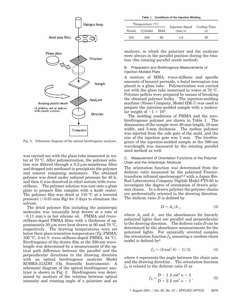
chematic diagram of the optical birefringence ana-yzer is shown in Fig. 3. Birefringence was deter-
ined by analysis of the relation between opticalntensity and rotating angle of a polarizer and an
Fig. 3. Schematic diagram of the optical birefringence analyzer.
nalyzer, in which the polarizer and the analyzerere always in the parallel position during the rota-
ion ~the rotating parallel nicols method!.
B. Preparation and Birefringence Measurements ofInjection-Molded Plate
A mixture of MMA, trans-stilbene and specificmounts of benzoyl peroxide, n-butyl mercaptan waslaced in a glass tube. Polymerization was carriedut with the glass tube immersed in water at 70 °C.olymer pellets were prepared by means of breakinghe obtained polymer bulks. The injection-moldingachine ~Nissei Company, Model HM-7! was used to
repare the injection-molded sample with a molecu-ar weight of ;1 3 105.
The molding conditions of PMMA and the zero-birefringence polymer are shown in Table 1. Thedimensions of the sample were 40-mm length, 10-mmwidth, and 3-mm thickness. The molten polymerwas injected from the side gate of the mold, and thesize of the injection gate was 3 mm. The birefrin-gence of the injection-molded sample at the 590-nmwavelength was measured by the rotating parallelnicol method as well.
C. Measurement of Orientation Functions of the PolymerChain and the Anisotropic Molecule
The orientation function was determined from thedichroic ratio measured by the polarized Fourier-transform infrared spectroscopy6,9 with a Japan Bio-Rad Laboratories Company Digilab Model FTS-65 toinvestigate the degree of orientation of drawn poly-mer chains. In a drawn polymer the polymer chainsare preferentially oriented in the drawing direction.The dichroic ratio D is defined by
D 5 AiyA', (3)
where Ai and A' are the absorbances for linearlypolarized lights that are parallel and perpendicularto the drawing direction. The dichroic ratio D can be
etermined by the absorbance measurements for theolarized lights. For uniaxially oriented sampleshe orientation function fD assuming a random-chain
model is defined by9
fD 5 ~3^cos2 u& 2 1!y2, (4)
here u represents the angle between the chain axisnd the drawing direction. The orientation function
D is related to the dichroic ratio D as
fD 5D 2 1D 1 2
2 cot2 a 1 22 cot2 a 2 1
, (5)
Temperature ~°C!Injection Speed
~mmys!Cooling Time
~s!Nozzle Cylinder Mold
235 240 60 1.6 80
1 August 2001 y Vol. 40, No. 22 y APPLIED OPTICS 3679
W
s
t
Tum
st
3
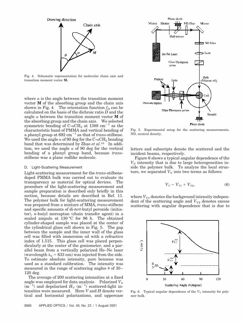
where a is the angle between the transition momentvector M of the absorbing group and the chain axisshown in Fig. 4. The orientation function fD can becalculated on the basis of the dichroic ratio D and theangle a between the transition moment vector M ofthe absorbing group and the chain axis. We selectedsymmetric bending of C-aCH3 at 1388 cm21 as thecharacteristic band of PMMA and vertical bending ofa phenyl group at 692 cm21 as that of trans-stilbene.
e used the angle a of 90 deg for the C-aCH3 bendingband that was determined by Zhao et al.10 In addi-tion, we used the angle a of 90 deg for the verticalbending of a phenyl group band, because trans-tilbene was a plane rodlike molecule.
D. Light-Scattering Measurement
Light-scattering measurement for the trans-stilbene-doped PMMA bulk was carried out to evaluate itstransparency as material for optical devices. Theprocedure of the light-scattering measurement andsample preparation is described only briefly in thissection, because details are described in Ref. 11.The polymer bulk for light-scattering measurementwas prepared from a mixture of MMA, trans-stilbeneand specific amounts of di-tert-butyl peroxide ~initia-or!, n-butyl mercaptan ~chain transfer agent! in a
sealed ampule at 130 °C for 96 h. The obtainedcylinder-shaped sample was placed at the center ofthe cylindrical glass cell shown in Fig. 5. The gapbetween the sample and the inner wall of the glasscell was filled with immersion oil with a refractiveindex of 1.515. This glass cell was placed perpen-dicularly at the center of the goniometer, and a par-allel beam from a vertically polarized He–Ne laser~wavelength l0 5 633 nm! was injected from the side.
o estimate absolute intensity, pure benzene wassed as a standard calibration. The intensity waseasured in the range of scattering angles u of 30–
120 deg.The average of 200 scattering intensities at a fixed
angle was employed for data analysis. Polarized VV~m21! and depolarized HV ~m21! scattered-light in-tensities were measured. Here V and H denote ver-tical and horizontal polarizations, and uppercase
Fig. 4. Schematic representation for molecular chain axis andtransition moment vector M.
680 APPLIED OPTICS y Vol. 40, No. 22 y 1 August 2001
letters and subscripts denote the scattered and theincident beams, respectively.
Figure 6 shows a typical angular dependence of theVV intensity that is due to large heterogeneities in-ide the polymer bulk. To analyze the local struc-ure, we separated VV into two terms as follows:
VV 5 VV1 1 VV2, (6)
where VV1 denotes the background intensity indepen-dent of the scattering angle and VV2 denotes excessscattering with angular dependence that is due to
Fig. 5. Experimental setup for the scattering measurements.ND, neutral density.
Fig. 6. Typical angular dependence of the VV intensity for poly-mer bulk.
12 iso
a
aoets
fisIp3
fcapup
amwiist9
large heterogeneity. The isotropic part VV1 of VV1is given by
VV1iso 5 VV1 2 ~4y3! HV. (7)
Scattering loss was estimated by means of integrat-ing the scattering intensities in all directions. Thetotal scattering loss atotal ~dBykm! contains threeterms, a1
iso, a2iso, and aaniso. Here a1
iso is the loss dueto the scattering VV1
iso without angular dependence,a2
iso is due to isotropic VV2 scattering with angulardependence, and aaniso is due to anisotropic scatter-ing HV.13
a1iso~dBykm! 5 1.16 3 104pVV1
iso, (8)
a2iso~dBykm! 5
1.35 3 108a3^h2&
n4l4
3 F ~b 1 2!2
b2~b 1 1!2
2~b 1 2!
b3 ln~b 1 1!G ,
(9)
b 5 ~16pa2yl2!, (10)
aniso~dBykm! 5 3.86 3 104pHV. (11)
Equation ~8! is obtained with Debye’s theory.14,15
Here a ~nanometers! is called the correlation lengthand is a measure of the size of the heterogeneousstructure inside the polymer. ^h2& denotes themean-square average of the fluctuation of all dielec-tric constants, n is the refractive-index of medium,and l ~nanometers! is the wavelength of light in themedium.
E. Other Measurements
The molecular weight was measured by gel perme-ation chromatography ~GPC; Tosoh Company, ModelHLC-8020! with tetrahydrofuran as a carrier. Theglass transition temperatures ~Tg! of polymers weremeasured with a differential scanning calorimeter~DSC; Rigaku Denki Company, Model DSC-8230B! at
heating rate of 10 °Cymin. The refractive indicesf polymers were measured with an Abbe refractom-ter ~ATAGO, Model 3!. The absorption spectrum ofrans-stilbene in PMMA bulk was measured by apectrophotometer ~Hitachi, Model U-2000!.
4. Results and Discussion
A. Compensation for Birefringence of Oriented Polymerby the Anisotropic Molecule Dope Method
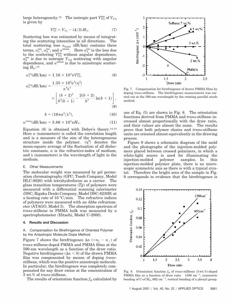
Figure 7 shows the birefringence Dn ~5ni 2 n'! oftrans-stilbene-doped PMMA and PMMA films at the590-nm wavelength as a function of the draw ratio.Negative birefringence ~Dn , 0! of the drawn PMMA
lm was compensated by means of doping trans-tilbene, which was the positive anisotropic molecule.n particular, the birefringence was completely com-ensated for any draw ratios at the concentration ofwt.% of trans-stilbene.The results of orientation function fD calculated by
use of Eq. ~5! are shown in Fig. 8. The orientationunctions derived from PMMA and trans-stilbene in-reased almost proportionally with the draw ratio,nd their values are almost the same. The resultsrove that both polymer chains and trans-stilbenenits are oriented almost equivalently in the drawingrocess.Figure 9 shows a schematic diagram of the mold
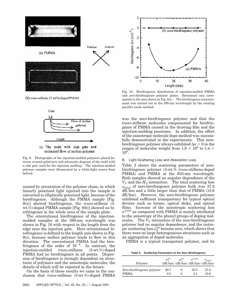
nd the photographs of the injection-molded poly-ers placed between crossed polarizers, in which ahite-light source is used for illuminating the
njection-molded polymer samples. In thisnjection-molded polymer plate, there is no micro-copic symmetric axis as there is with a typical crys-al. Therefore the bright area of the sample in Fig.
corresponds to evidence that the birefringence is
Fig. 7. Compensation for birefringence of drawn PMMA films bydoping trans-stilbene. The birefringence measurement was car-ried out at the 590-nm wavelength by the rotating parallel nicolsmethod.
Fig. 8. Orientation function fD of trans-stilbene ~3-wt.%!-dopedPMMA film as a function of draw ratio. 1388 cm21, symmetricbending of C-aCH3; 692 cm21, vertical bending of a phenyl group.
1 August 2001 y Vol. 40, No. 22 y APPLIED OPTICS 3681
9wr
mser9df
PBV
edfia
3
caused by orientation of the polymer chain, in whichlinearly polarized light injected into the sample isconverted to elliptically polarized light, because of thebirefringence. Although the PMMA sample @Fig.~a!# showed birefringence, the trans-stilbene ~3-t.%!-doped PMMA sample @Fig. 9~b!# showed no bi-
efringence in the whole area of the sample plate.The orientational birefringence of the injection-olded samples at the 590-nm wavelength was
hown in Fig. 10 with respect to the length from thedge near the injection gate. Here orientational bi-efringence is defined to the length axis shown in Fig.~c!, because molten polymer tends to flow in thisirection. The conventional PMMA had the bire-ringence of the order of 1026. In contrast, the
injection-molded trans-stilbene ~3-wt.%!-dopedPMMA had no birefringence in all points. Disper-sion of birefringence is strongly dependent on struc-tures of polymers and the anisotropic molecules, thedetails of which will be reported in the future.
On the basis of these results we came to the con-clusion that trans-stilbene ~3-wt.%!-doped PMMA
Fig. 9. Photographs of the injection-molded polymers placed be-tween crossed polarizers and schematic diagram of the mold witha side gate used for the injection molding. The injection-moldedpolymer samples were illuminated by a white-light source frombehind.
682 APPLIED OPTICS y Vol. 40, No. 22 y 1 August 2001
was the zero-birefringence polymer and that thetrans-stilbene molecules compensated for birefrin-gence of PMMA caused in the drawing film and theinjection-molding processes. In addition, the effectof the anisotropic molecule dope method was success-fully demonstrated in the experiments. This zero-birefringence polymer always exhibited Dn 5 0 in theranges of molecular weight from 1.0 3 105 to 1.4 3106.
B. Light-Scattering Loss and Absorption Loss
Table 2 shows the scattering parameters of zero-birefringence polymer ~3-wt.% trans-stilbene-doped
MMA! and PMMA at the 633-nm wavelength.oth samples showed no angular dependence of theV and the HV intensities. The total scattering loss
atotal of zero-birefringence polymer bulk was 37.2dBykm and a little larger than that of PMMA ~13.6dBykm!. However, the zero-birefringence polymerxhibited sufficient transparency for typical opticalevices such as lenses, optical disks, and opticallms. Increase of the anisotropic scattering lossaniso as compared with PMMA is mainly attributed
to the anisotropy of the phenyl groups of doping mol-ecules. The VV intensities of the zero-birefringencepolymer had no angular dependence, and the isotro-pic scattering loss a2
iso became zero, which shows thatthere were no large heterogeneous structures such asan aggregation of doped molecules.
PMMA is a typical transparent polymer, and its
Fig. 10. Birefringence distribution of injection-molded PMMAand zero-birefringence polymer plates. Horizontal axis corre-sponds to the axis shown in Fig. 8~c!. The birefringence measure-ment was carried out at the 590-nm wavelength by the rotatingparallel nicols method.
Table 2. Scattering Parameters of the Zero Birefringence
Polymera1
iso
~dBykm!a2
iso
~dBykm!aaniso
~dBykm!atotal
~dBykm!
Zero-birefringence polymer 20.7 0 16.5 37.2PMMA 9.5 0 4.1 13.6
bsvdg
taomleT~
ptvw6
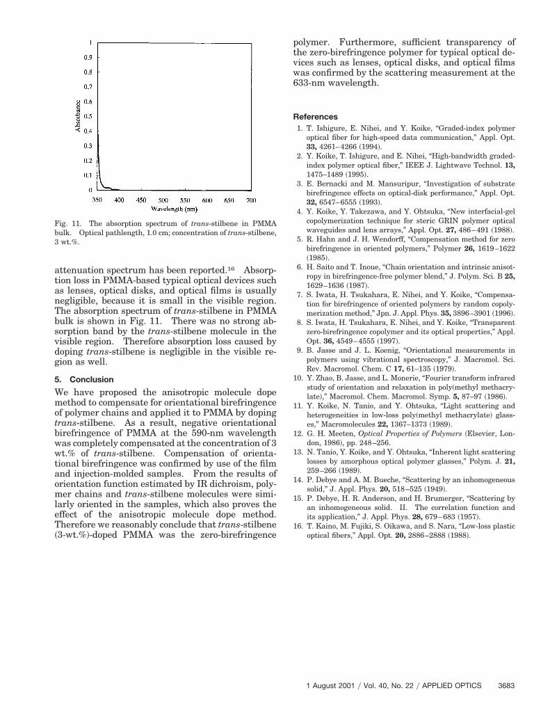
attenuation spectrum has been reported.16 Absorp-tion loss in PMMA-based typical optical devices suchas lenses, optical disks, and optical films is usuallynegligible, because it is small in the visible region.The absorption spectrum of trans-stilbene in PMMAulk is shown in Fig. 11. There was no strong ab-orption band by the trans-stilbene molecule in theisible region. Therefore absorption loss caused byoping trans-stilbene is negligible in the visible re-ion as well.
5. Conclusion
We have proposed the anisotropic molecule dopemethod to compensate for orientational birefringenceof polymer chains and applied it to PMMA by dopingtrans-stilbene. As a result, negative orientationalbirefringence of PMMA at the 590-nm wavelengthwas completely compensated at the concentration of 3wt.% of trans-stilbene. Compensation of orienta-ional birefringence was confirmed by use of the filmnd injection-molded samples. From the results ofrientation function estimated by IR dichroism, poly-er chains and trans-stilbene molecules were simi-
arly oriented in the samples, which also proves theffect of the anisotropic molecule dope method.herefore we reasonably conclude that trans-stilbene
3-wt.%!-doped PMMA was the zero-birefringence
Fig. 11. The absorption spectrum of trans-stilbene in PMMAbulk. Optical pathlength, 1.0 cm; concentration of trans-stilbene,3 wt.%.
olymer. Furthermore, sufficient transparency ofhe zero-birefringence polymer for typical optical de-ices such as lenses, optical disks, and optical filmsas confirmed by the scattering measurement at the33-nm wavelength.
References1. T. Ishigure, E. Nihei, and Y. Koike, “Graded-index polymer
optical fiber for high-speed data communication,” Appl. Opt.33, 4261–4266 ~1994!.
2. Y. Koike, T. Ishigure, and E. Nihei, “High-bandwidth graded-index polymer optical fiber,” IEEE J. Lightwave Technol. 13,1475–1489 ~1995!.
3. E. Bernacki and M. Mansuripur, “Investigation of substratebirefringence effects on optical-disk performance,” Appl. Opt.32, 6547–6555 ~1993!.
4. Y. Koike, Y. Takezawa, and Y. Ohtsuka, “New interfacial-gelcopolymerization technique for steric GRIN polymer opticalwaveguides and lens arrays,” Appl. Opt. 27, 486–491 ~1988!.
5. R. Hahn and J. H. Wendorff, “Compensation method for zerobirefringence in oriented polymers,” Polymer 26, 1619–1622~1985!.
6. H. Saito and T. Inoue, “Chain orientation and intrinsic anisot-ropy in birefringence-free polymer blend,” J. Polym. Sci. B 25,1629–1636 ~1987!.
7. S. Iwata, H. Tsukahara, E. Nihei, and Y. Koike, “Compensa-tion for birefringence of oriented polymers by random copoly-merization method,” Jpn. J. Appl. Phys. 35, 3896–3901 ~1996!.
8. S. Iwata, H. Tsukahara, E. Nihei, and Y. Koike, “Transparentzero-birefringence copolymer and its optical properties,” Appl.Opt. 36, 4549–4555 ~1997!.
9. B. Jasse and J. L. Koenig, “Orientational measurements inpolymers using vibrational spectroscopy,” J. Macromol. Sci.Rev. Macromol. Chem. C 17, 61–135 ~1979!.
10. Y. Zhao, B. Jasse, and L. Monerie, “Fourier transform infraredstudy of orientation and relaxation in poly~methyl methacry-late!,” Macromol. Chem. Macromol. Symp. 5, 87–97 ~1986!.
11. Y. Koike, N. Tanio, and Y. Ohtsuka, “Light scattering andheterogeneities in low-loss poly~methyl methacrylate! glass-es,” Macromolecules 22, 1367–1373 ~1989!.
12. G. H. Meeten, Optical Properties of Polymers ~Elsevier, Lon-don, 1986!, pp. 248–256.
13. N. Tanio, Y. Koike, and Y. Ohtsuka, “Inherent light scatteringlosses by amorphous optical polymer glasses,” Polym. J. 21,259–266 ~1989!.
14. P. Debye and A. M. Bueche, “Scattering by an inhomogeneoussolid,” J. Appl. Phys. 20, 518–525 ~1949!.
15. P. Debye, H. R. Anderson, and H. Brumerger, “Scattering byan inhomogeneous solid. II. The correlation function andits application,” J. Appl. Phys. 28, 679–683 ~1957!.
16. T. Kaino, M. Fujiki, S. Oikawa, and S. Nara, “Low-loss plasticoptical fibers,” Appl. Opt. 20, 2886–2888 ~1988!.
1 August 2001 y Vol. 40, No. 22 y APPLIED OPTICS 3683