Embed Size (px)
Citation preview
The information contained herein is, to the best of our knowledge, accurate and applicable for proper operation and installation of the specified equipment at the time this document entered service. Before proceeding, it is recommended that you check for a more current version of this Installation Operation Manual (IOM) on our website at www.pennbarry.com.
Read carefully before attempting to assemble, install, operate or maintain the product described. Protect yourself and others by observing all safety information. Failure to comply with instructions could result in personal injury and/or property damage! Retain instructions for future reference.
IMPORTANT!READ BEFORE PROCEEDING!
TM OPERATION & MAINTENANCE MANUAL
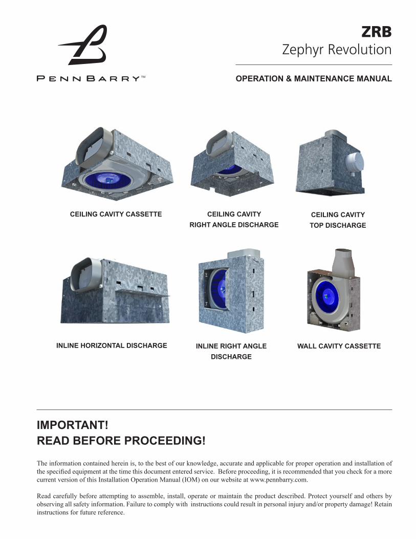
ZRBZephyr Revolution
CEILING CAVITY CASSETTE CEILING CAVITY RIGHT ANGLE DISCHARGE
CEILING CAVITY TOP DISCHARGE
INLINE HORIZONTAL DISCHARGE INLINE RIGHT ANGLE DISCHARGE
WALL CAVITY CASSETTE
PENNBARRY 2
TABLE OF CONTENTS
INTRODUCTION 3INSTALLATION 4IMPORTANT SAFETY INSTRUCTIONS 4WARNINGS AND CAUTIONS 4RECEIVING AND HANDLING 6UNPACKING 6INSTALLATION 6A. Unit Installation 6A.1 Ceiling Units 6A.2 Inline Horizontal Discharge and Inline Right Angle
Discharge Units 8A.3 Wall Cavity Cassette Unit 9A.4 Unit to Duct Connections 10A.5 Installation Recommendations 11A.6 Ductwork and Noise Considerations 12A.7 Filters 12B. Electrical Connections 12C. Grille and Lighting Installation 13D. Fire Damper Installation 13E. Start-up Checklist 13RECOMMENDED MAINTENANCE 14ACCESSORIES 15EXPLODED VIEWS 16DIMENSIONS 22TROUBLESHOOTING CHECKLIST 28

PENNBARRY 3
INTRODUCTION
PennBarry Zephyr Revolution interior exhaust fans are designed for applications where a low noise, high reliability ceiling or wall exhaust fan is required. With air capacities from 100 to 450 CFM (169 to 764 m^3/hr) and static pressure up to 1 in. wg. (248 Pa), they are ideally suited for use in ventilating server rooms, bathrooms, or other low to medium CFM applications. Housings are fabricated using sturdy 18 gauge galvanized steel to ensure durability. Acoustic insulation, in combination with performance optimized direct drive, EC motor and wheel assemblies, lowers sound levels and improves air performance. Motors are rigidly mounted, and for inline units, vibration isolators may be added to further minimize noise levels. Together, these features ensure years of problem free, quiet operation.
PENNBARRY 4
INSTALLATION
IMPORTANT SAFETY INSTRUCTIONSREAD AND SAVE THESE INSTRUCTIONS
WARNINGS AND CAUTIONS
To reduce the risk of fire, electric shock, or injury to persons, observe the following:
WARNING
1. Use this unit only in the manner intended by the manufacturer. If you have questions, contact the manufacturer. FOR INDOOR USE ONLY. 2. Before servicing or cleaning unit, switch power off at service
panel and lock the service disconnecting means to prevent power from being switched on accidentally. When the service disconnecting means cannot be locked, securely fasten a prominent warning device, such as a tag, to the service panel.
3. Installation work and electrical wiring must be done by qualified person(s) in accordance with all applicable codes and standards, including fire-rated construction.
4. Sufficient air is needed for proper combustion and exhausting of gases through the flue (chimney) of fuel burning equipment to prevent back drafting. Follow the heating equipment manufacturer’s guideline and safety standards such as those published by the National Fire Protection Association (NFPA), and the American Society for Heating, Refrigeration and Air Conditioning Engineers (ASHRAE), and the local code authorities.
5. When cutting or drilling into wall or ceiling, do not damage electrical wiring and other hidden utilities.
6. Ducted fans must always be vented to the outdoors.7. If this unit is to be installed over a tub or shower, it must be
marked as appropriate for the application and be connected to a GFCI (Ground Fault Circuit Interrupter) - protected branch circuit.
8. Wall unit must be installed with a minimum five feet (1.5m) mounting height from the floor.
9. Ceiling units must be installed with a minimum 8.2 feet (2.5m) mounting height from the floor.
10. To avoid the risk of personal injury or property damage from fire, avoid skin or flammable material contact with LED heat sink and LED lens.
11. To reduce the risk of fire or electric shock, do not use this fan with any solid-state speed control device.
12. For wall insert mounting, the fan must be installed above a counter or large appliance that serves as a barrier.
13. Never place a switch where it can be reached from a tub or shower.
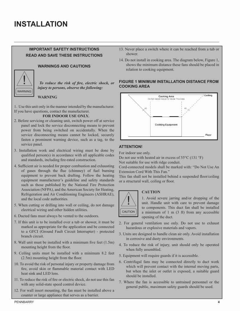
14. Do not install in cooking area. The diagram below, Figure 1, shows the minimum distance these fans should be placed in relation to cooking equipment.
FIGURE 1 MINIMUM INSTALLATION DISTANCE FROM COOKING AREA
ATTENTION! For indoor use only. Do not use with heated air in excess of 55°C (131 °F)Not suitable for use with ridge conduit.Cord-connected models shall be marked with: “Do Not Use An Extension Cord With This Fan.”This fan shall not be installed behind a suspended floor/ceiling or a structural wall, ceiling or floor.
CAUTION1. Avoid severe jarring and/or dropping of the unit. Handle unit with care to prevent damage to components. This duct fan shall be installed a minimum of 1 m (3 ft) from any accessible opening of the duct.
2. For general ventilation use only. Do not use to exhaust hazardous or explosive materials and vapors.
3. Units are designed to handle clean air only. Avoid installation in corrosive and dusty environments.
4. To reduce the risk of injury, unit should only be operated when fully assembled.
5. Equipment will require guards if it is accessible.6. Centrifugal fans may be connected directly to duct work
which will prevent contact with the internal moving parts, but when the inlet or outlet is exposed, a suitable guard should be installed.
7. Where the fan is accessible to untrained personnel or the general public, maximum safety guards should be used.
PENNBARRY 5
INSTALLATION (CONTINUED)
AVERTISSEMENT!INSTRUCTIONS DE SÉCURITÉ IMPORTANTES
LIRE ET CONSERVER CES INSTRUCTIONSAVERTISSEMENTS ET MISES EN GARDE
Veuillez suivre les consignes suivantes afin de réduire le risque d’incendie, de décharge électrique ou de blessures corporelles :
1. Utilisez cette unité uniquement de la façon prévue par le fabricant. Si vous avez des questions, veuillez contacter le fabricant.
2. Avant d’effectuer l’entretien ou le nettoyage de l’unité, veuillez éteindre celle-ci sur le panneau de service et verrouiller les dispositifs de sectionnement afin d’empêcher l’alimentation d’être remise en fonction accidentellement. Lorsqu’il est impossible de verrouiller les dispositifs de sectionnement, fixez un dispositif d’avertissement bien visible comme une étiquette au panneau de service.
3. Les travaux d’installation et de câblage électrique doivent être effectués par une personne qualifiée selon les codes et les normes applicables, incluant les travaux de construction classés résistants au feu.
4. Un apport d’air suffisant est nécessaire pour assurer une bonne combustion ainsi qu’une bonne évacuation des gaz émanant de tout appareil de combustion par le conduit (cheminée) afin d’éviter le refoulement de l’air. Suivez les directives de sécurité du fabricant de l’équipement de chauffage et les normes de sécurité comme celles publiées par la National Fire Protection Association (NFPA) et l’American Society for Heating, Refrigeration and Air Conditioning Engineers (ASHRAE) ainsi que celles des autorités locales.
5. Lorsque vous coupez ou percez un trou dans un mur ou au plafond, faites attention de ne pas endommager les câbles électriques ainsi que les autres dispositifs des services publics.
6. Les systèmes de ventilation à conduits d’air doivent toujours être ventilés vers l’extérieur.
7. Si l’unité doit être installée au-dessus d’une baignoire ou d’une douche, elle doit être marquée comme appropriée pour cette utilisation et doit être connectée à un disjoncteur différentiel de fuite à la terre (GFCI) protégé par un circuit de dérivation.
8. L’unité murale peut être installée à un minimum de 1,5 m (5 pi) du plancher.
9. L’unité murale peut être installée à un minimum de 2,5m (8,2 pi) du plancher.
10. Afin d’éviter le risque de blessures corporelles et de dommages à la propriété provoqués par les risques d’incendie, évitez les contacts de la peau ou des matériaux inflammables avec le dissipateur thermique DEL et les lentilles DEL.
11. Afin de réduire le risque d’incendie ou de décharge électrique,
n’utilisez pas ce ventilateur avec une commande de vitesse à semi-conducteur.
12. Pour les installations murales encastrées, le ventilateur doit être installé au-dessus d’un comptoir ou d’un appareil qui sert de barrière.
13. Ne placez jamais un commutateur à un endroit où il peut être atteint à partir d’une baignoire ou d’une douche.
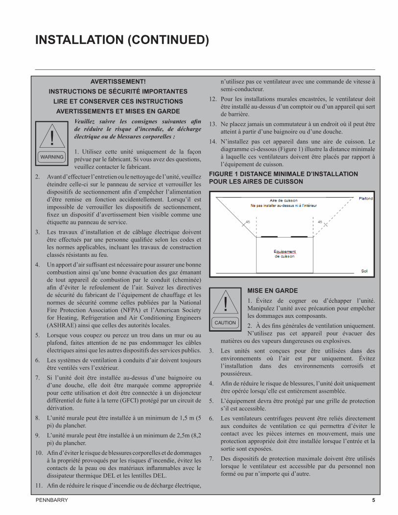
14. N’installez pas cet appareil dans une aire de cuisson. Le diagramme ci-dessous (Figure 1) illustre la distance minimale à laquelle ces ventilateurs doivent être placés par rapport à l’équipement de cuisson.
FIGURE 1 DISTANCE MINIMALE D’INSTALLATION POUR LES AIRES DE CUISSON
MISE EN GARDE1. Évitez de cogner ou d’échapper l’unité. Manipulez l’unité avec précaution pour empêcher les dommages aux composants. 2. À des fins générales de ventilation uniquement. N’utilisez pas cet appareil pour évacuer des
matières ou des vapeurs dangereuses ou explosives.3. Les unités sont conçues pour être utilisées dans des
environnements où l’air est pur uniquement. Évitez l’installation dans des environnements corrosifs et poussiéreux.
4. Afin de réduire le risque de blessures, l’unité doit uniquement être opérée lorsqu’elle est entièrement assemblée.
5. L’équipement devra être protégé par une grille de protection s’il est accessible.
6. Les ventilateurs centrifuges peuvent être reliés directement aux conduites de ventilation ce qui permettra d’éviter le contact avec les pièces internes en mouvement, mais une protection appropriée doit être installée lorsque l’entrée et la sortie sont exposées.
7. Des dispositifs de protection maximale doivent être utilisés lorsque le ventilateur est accessible par du personnel non formé ou par n’importe qui d’autre.
PENNBARRY 6
INSTALLATION (CONTINUED)
RECEIVING AND HANDLINGPennBarry fans are carefully inspected before leaving the factory. When the unit is received, inspect the carton for any signs of tampering. Inspect the unit for any damage that may have occurred during transit and check for loose, missing or damaged parts. Mishandled units can void the warranty provisions. PennBarry is not responsible for damages incurred during shipment.
STORAGELong-term storage requires special attention. Unit should be stored on a level, solid surface, preferably indoors. If outside storage is necessary, protect the unit against moisture and dirt by encasing the carton in plastic or some similar weatherproof material. Periodically inspect the unit to ensure its integrity.
UNPACKING1. Place carton in an upright position and remove staples
and sealing tape at the top of the carton as needed without damaging the contents.
2. Open carton flaps. Remove any cardboard and filler pieces, as well as any components or accessories shipped with the unit.
3. Carefully remove the unit from the carton. Inspect the unit for any damage that may have occurred during transit and check for loose, missing or damaged parts. To view your respective Zephyr Revolution configuration, see Figures 17 to 22 in the Exploded Views section. The Zephyr Revolution comes in six configurations:
i. Ceiling cavity cassetteii. Ceiling cavity right angle dischargeiii. Ceiling cavity top dischargeiv. Inline horizontal dischargev. Inline right angle dischargevi. Wall cavity cassette4. Check for and remove any loose hardware or particles from
the inside of the fan housing. Check wheel to ensure it rotates freely.
A. UNIT INSTALLATIONA.1 Ceiling UnitsCeiling Cavity Cassette, Ceiling Cavity Right Angle Discharge, and Ceiling Cavity Top Discharge Units Ceiling units must be installed with a minimum 8.2 feet (2.5m) mounting height from the floor. The unit must not be installed in a ceiling thermally insulated to a value greater than R40.
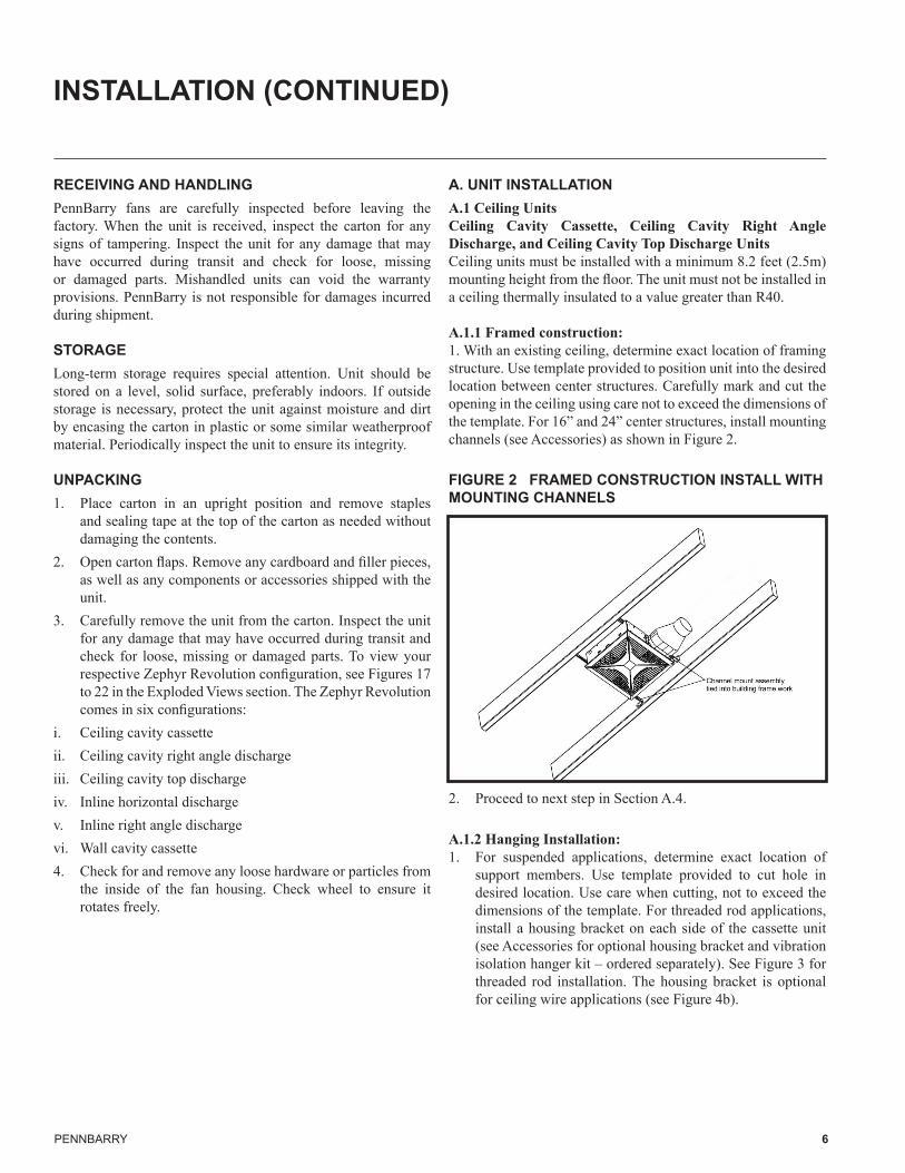
A.1.1 Framed construction:1. With an existing ceiling, determine exact location of framing structure. Use template provided to position unit into the desired location between center structures. Carefully mark and cut the opening in the ceiling using care not to exceed the dimensions of the template. For 16” and 24” center structures, install mounting channels (see Accessories) as shown in Figure 2.
FIGURE 2 FRAMED CONSTRUCTION INSTALL WITH MOUNTING CHANNELS
2. Proceed to next step in Section A.4.
A.1.2 Hanging Installation:1. For suspended applications, determine exact location of
support members. Use template provided to cut hole in desired location. Use care when cutting, not to exceed the dimensions of the template. For threaded rod applications, install a housing bracket on each side of the cassette unit (see Accessories for optional housing bracket and vibration isolation hanger kit – ordered separately). See Figure 3 for threaded rod installation. The housing bracket is optional for ceiling wire applications (see Figure 4b).

PENNBARRY 7
INSTALLATION (CONTINUED)
FIGURE 3 HOUSING BRACKET INSTALLATION FOR THREADED ROD
2. Position brackets such that bottom edge of cassette will be flush with finished ceiling and tighten and secure hardware as shown in Figure 4a or Figure 4b. Care should be taken to ensure the cassette is at ceiling level and the rail is properly suspended with ¼” threaded rod or 1/8” 12 gauge ceiling wire. Note that ceiling wire and threaded rod are field provided.
FIGURE 4A THREADED ROD INSTALLATION
FIGURE 4B CEILING WIRE INSTALLATION
3. Proceed to next step in Section A.4.A.1.3 Retrofit Installation - Existing Ceiling with No AccessThe Zephyr Revolution can be installed in a retrofit application
from inside a room.1. Place mounting channels in desired location and attach to
building structure. 2. Attach duct to cassette outlet.3. Place duct back in ceiling through outlet access cutout.4. Secure cassette to mounting channel driving the screws from
inside of the cassette out into the attic space.5. Go to next step in Section B Electrical Connections.Note that for retrofit installations, the unit can be fully dismantled
as shown in an example in Figure 5. For the exploded images, go to the Exploded Views section, Figures 17 to 22.
FIGURE 5 CEILING CAVITY RIGHT ANGLE DISCHARGE UNIT CONFIGURATION EXAMPLE
A.2 Inline Horizontal Discharge and Inline Right Angle Discharge Units
1. Install housing brackets (order separately in Accessories). 2. Secure ¼” threaded rods or ceiling wire to housing brackets
(see Figures 4a and 4b) as required (threaded rods and ceiling wire are field provided).
3. Suspend unit to align with duct. See Figures 6 and 7 for inline horizontal and inline right angle units respectively.
PENNBARRY 8
INSTALLATION (CONTINUED)
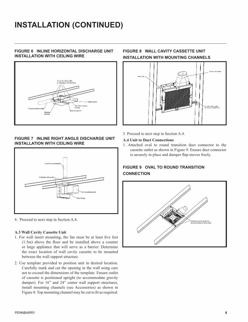
FIGURE 6 INLINE HORIZONTAL DISCHARGE UNIT INSTALLATION WITH CEILING WIRE
FIGURE 7 INLINE RIGHT ANGLE DISCHARGE UNIT INSTALLATION WITH CEILING WIRE
4. Proceed to next step in Section A.4.
A.3 Wall Cavity Cassette Unit1. For wall insert mounting, the fan must be at least five feet
(1.5m) above the floor and be installed above a counter or large appliance that will serve as a barrier. Determine the exact location of wall cavity cassette to be mounted between the wall support structure.
2. Use template provided to position unit in desired location. Carefully mark and cut the opening in the wall using care not to exceed the dimensions of the template. Ensure outlet of cassette is positioned upright (to accommodate gravity damper). For 16” and 24” center wall support structures, install mounting channels (see Accessories) as shown in Figure 8. Top mounting channel may be cut to fit as required.
FIGURE 8 WALL CAVITY CASSETTE UNIT INSTALLATION WITH MOUNTING CHANNELS
3. Proceed to next step in Section A.4.A.4 Unit to Duct Connections1. Attached oval to round transition duct connector to the
cassette outlet as shown in Figure 9. Ensure duct connector is securely in place and damper flap moves freely.
FIGURE 9 OVAL TO ROUND TRANSITION CONNECTION
PENNBARRY 9
INSTALLATION (CONTINUED)
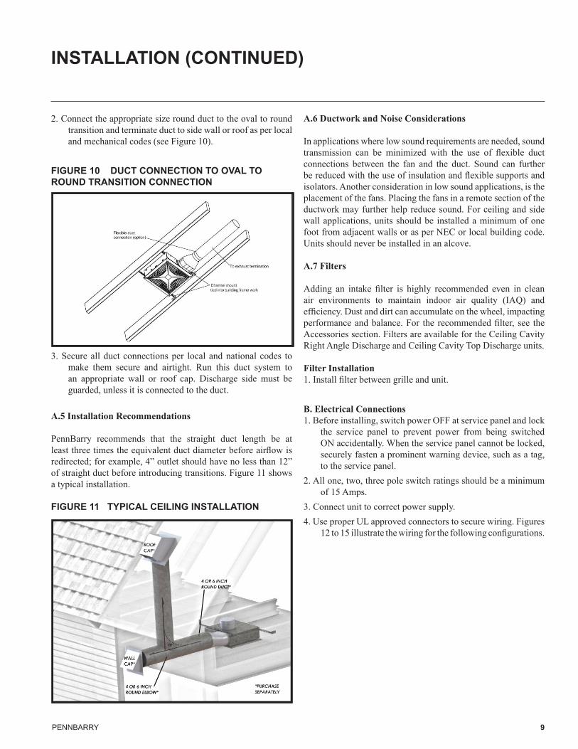
2. Connect the appropriate size round duct to the oval to round transition and terminate duct to side wall or roof as per local and mechanical codes (see Figure 10).
FIGURE 10 DUCT CONNECTION TO OVAL TO ROUND TRANSITION CONNECTION
3. Secure all duct connections per local and national codes to make them secure and airtight. Run this duct system to an appropriate wall or roof cap. Discharge side must be guarded, unless it is connected to the duct.
A.5 Installation Recommendations
PennBarry recommends that the straight duct length be at least three times the equivalent duct diameter before airflow is redirected; for example, 4” outlet should have no less than 12” of straight duct before introducing transitions. Figure 11 shows a typical installation.
FIGURE 11 TYPICAL CEILING INSTALLATION
A.6 Ductwork and Noise Considerations
In applications where low sound requirements are needed, sound transmission can be minimized with the use of flexible duct connections between the fan and the duct. Sound can further be reduced with the use of insulation and flexible supports and isolators. Another consideration in low sound applications, is the placement of the fans. Placing the fans in a remote section of the ductwork may further help reduce sound. For ceiling and side wall applications, units should be installed a minimum of one foot from adjacent walls or as per NEC or local building code. Units should never be installed in an alcove.
A.7 Filters
Adding an intake filter is highly recommended even in clean air environments to maintain indoor air quality (IAQ) and efficiency. Dust and dirt can accumulate on the wheel, impacting performance and balance. For the recommended filter, see the Accessories section. Filters are available for the Ceiling Cavity Right Angle Discharge and Ceiling Cavity Top Discharge units.
Filter Installation1. Install filter between grille and unit.
B. Electrical Connections1. Before installing, switch power OFF at service panel and lock
the service panel to prevent power from being switched ON accidentally. When the service panel cannot be locked, securely fasten a prominent warning device, such as a tag, to the service panel.
2. All one, two, three pole switch ratings should be a minimum of 15 Amps.
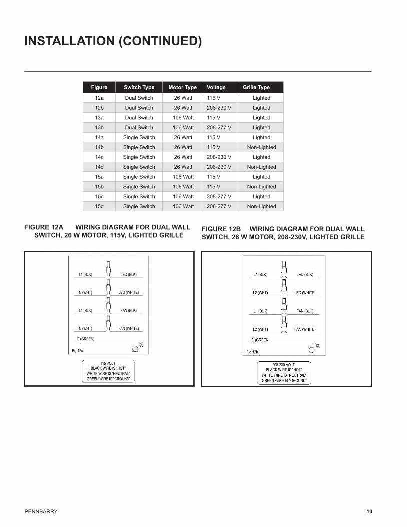
3. Connect unit to correct power supply. 4. Use proper UL approved connectors to secure wiring. Figures
12 to 15 illustrate the wiring for the following configurations.
PENNBARRY 10
INSTALLATION (CONTINUED)
FIGURE 12A WIRING DIAGRAM FOR DUAL WALL SWITCH, 26 W MOTOR, 115V, LIGHTED GRILLE
FIGURE 12B WIRING DIAGRAM FOR DUAL WALL SWITCH, 26 W MOTOR, 208-230V, LIGHTED GRILLE
Figure Switch Type Motor Type Voltage Grille Type
12a Dual Switch 26 Watt 115 V Lighted
12b Dual Switch 26 Watt 208-230 V Lighted
13a Dual Switch 106 Watt 115 V Lighted
13b Dual Switch 106 Watt 208-277 V Lighted
14a Single Switch 26 Watt 115 V Lighted
14b Single Switch 26 Watt 115 V Non-Lighted
14c Single Switch 26 Watt 208-230 V Lighted
14d Single Switch 26 Watt 208-230 V Non-Lighted
15a Single Switch 106 Watt 115 V Lighted
15b Single Switch 106 Watt 115 V Non-Lighted
15c Single Switch 106 Watt 208-277 V Lighted
15d Single Switch 106 Watt 208-277 V Non-Lighted
PENNBARRY 11
INSTALLATION (CONTINUED)
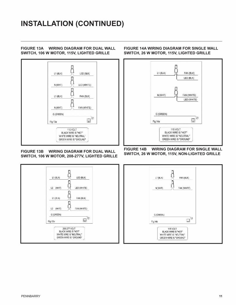
FIGURE 13A WIRING DIAGRAM FOR DUAL WALL SWITCH, 106 W MOTOR, 115V, LIGHTED GRILLE
FIGURE 13B WIRING DIAGRAM FOR DUAL WALL SWITCH, 106 W MOTOR, 208-277V, LIGHTED GRILLE
FIGURE 14A WIRING DIAGRAM FOR SINGLE WALL SWITCH, 26 W MOTOR, 115V, LIGHTED GRILLE
FIGURE 14B WIRING DIAGRAM FOR SINGLE WALL SWITCH, 26 W MOTOR, 115V, NON-LIGHTED GRILLE
PENNBARRY 12
INSTALLATION (CONTINUED)
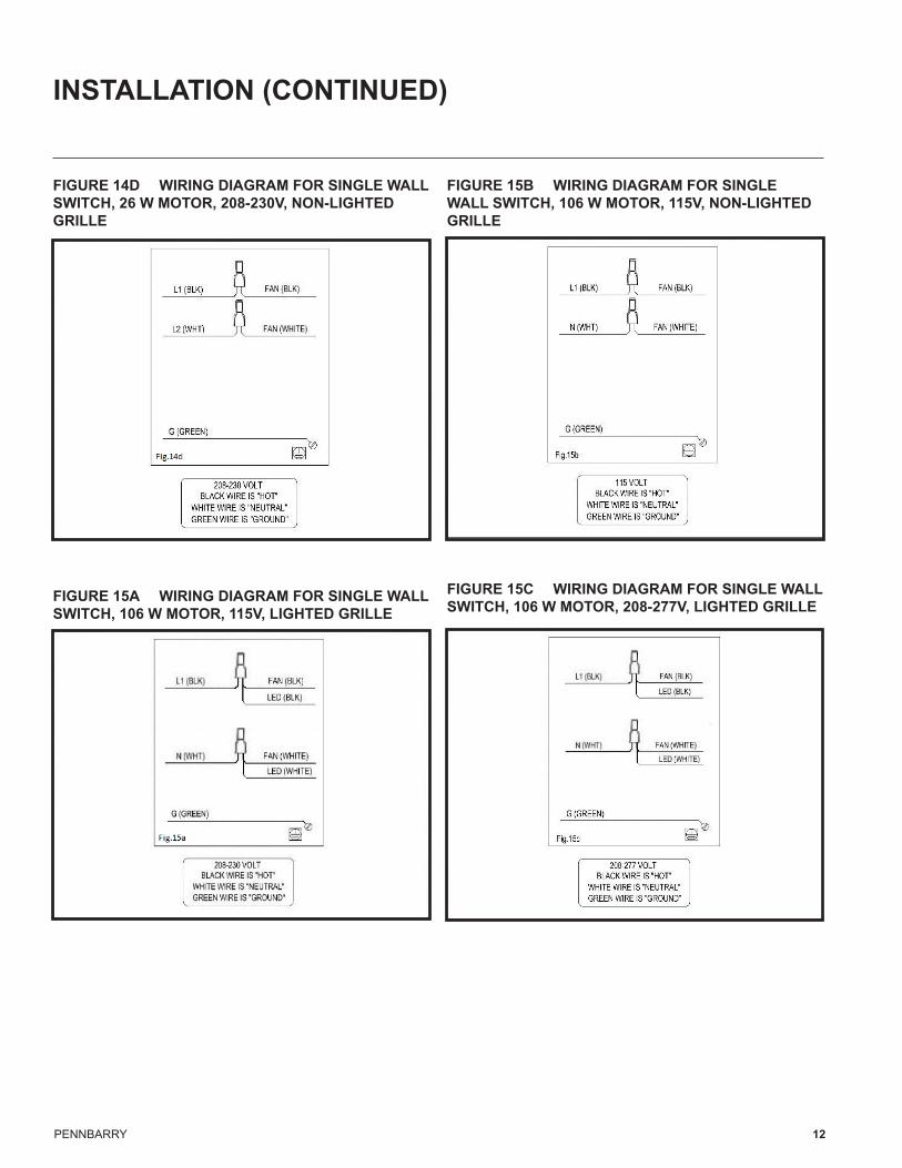
FIGURE 14D WIRING DIAGRAM FOR SINGLE WALL SWITCH, 26 W MOTOR, 208-230V, NON-LIGHTED GRILLE
FIGURE 15A WIRING DIAGRAM FOR SINGLE WALL SWITCH, 106 W MOTOR, 115V, LIGHTED GRILLE
FIGURE 15B WIRING DIAGRAM FOR SINGLE WALL SWITCH, 106 W MOTOR, 115V, NON-LIGHTED GRILLE
FIGURE 15C WIRING DIAGRAM FOR SINGLE WALL SWITCH, 106 W MOTOR, 208-277V, LIGHTED GRILLE
PENNBARRY 13
INSTALLATION (CONTINUED)
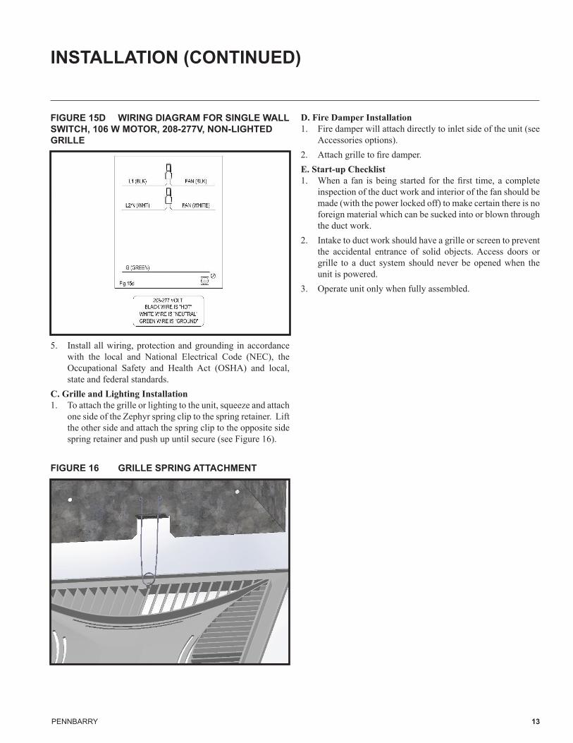
FIGURE 15D WIRING DIAGRAM FOR SINGLE WALL SWITCH, 106 W MOTOR, 208-277V, NON-LIGHTED GRILLE
5. Install all wiring, protection and grounding in accordance with the local and National Electrical Code (NEC), the Occupational Safety and Health Act (OSHA) and local, state and federal standards.
C. Grille and Lighting Installation1. To attach the grille or lighting to the unit, squeeze and attach
one side of the Zephyr spring clip to the spring retainer. Lift the other side and attach the spring clip to the opposite side spring retainer and push up until secure (see Figure 16).
FIGURE 16 GRILLE SPRING ATTACHMENT
D. Fire Damper Installation1. Fire damper will attach directly to inlet side of the unit (see
Accessories options). 2. Attach grille to fire damper.E. Start-up Checklist1. When a fan is being started for the first time, a complete
inspection of the duct work and interior of the fan should be made (with the power locked off) to make certain there is no foreign material which can be sucked into or blown through the duct work.
2. Intake to duct work should have a grille or screen to prevent the accidental entrance of solid objects. Access doors or grille to a duct system should never be opened when the unit is powered.
3. Operate unit only when fully assembled.
PENNBARRY 14
MAINTENANCE
RECOMMENDED MAINTENANCEZephyr fans require minimal maintenance. Motors have permanently sealed bearings and do not require oiling. Inspect the units as required based on application, to address any potential problems which may lead to a loss of performance or early failure.
1. When performing maintenance, ensure power is disconnected and secured.
2. Maintenance and cleaning tasks should be performed by an authorized technician to check for dirt, dust, loose wire connections and for replacing light fixtures or connections. Gently remove build up on the wheel and scroll as needed. Excessive build up may cause unbalanced operation.
3. If a filter is installed, check and gently clean the washable aluminum filter with water as needed.
PENNBARRY 15
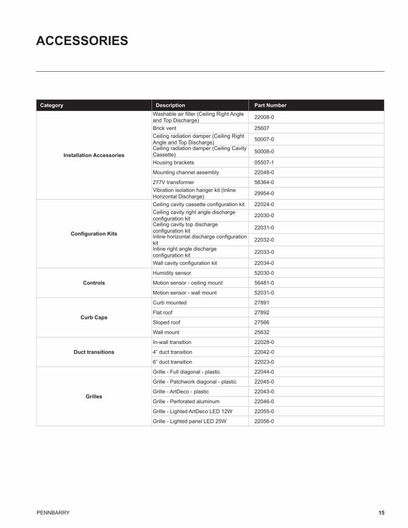
ACCESSORIES
Category Description Part Number
Installation Accessories
Washable air filter (Ceiling Right Angle and Top Discharge) 22008-0
Brick vent 25607Ceiling radiation damper (Ceiling Right Angle and Top Discharge) 50007-0
Ceiling radiation damper (Ceiling Cavity Cassette) 50008-0
Housing brackets 05507-1
Mounting channel assembly 22048-0
277V transformer 56364-0Vibration isolation hanger kit (Inline Horizontal Discharge) 29954-0
Configuration Kits
Ceiling cavity cassette configuration kit 22024-0Ceiling cavity right angle discharge configuration kit 22030-0
Ceiling cavity top discharge configuration kit 22031-0
Inline horizontal discharge configuration kit 22032-0
Inline right angle discharge configuration kit 22033-0
Wall cavity configuration kit 22034-0
Controls
Humidity sensor 52030-0
Motion sensor - ceiling mount 56481-0
Motion sensor - wall mount 52031-0
Curb Caps
Curb mounted 27891
Flat roof 27892
Sloped roof 27566
Wall mount 25632
Duct transitions
In-wall transition 22028-0
4” duct transition 22042-0
6” duct transition 22023-0
Grilles
Grille - Full diagonal - plastic 22044-0
Grille - Patchwork diagonal - plastic 22045-0
Grille - ArtDeco - plastic 22043-0
Grille - Perforated aluminum 22046-0
Grille - Lighted ArtDeco LED 12W 22055-0
Grille - Lighted panel LED 25W 22056-0
PENNBARRY 16
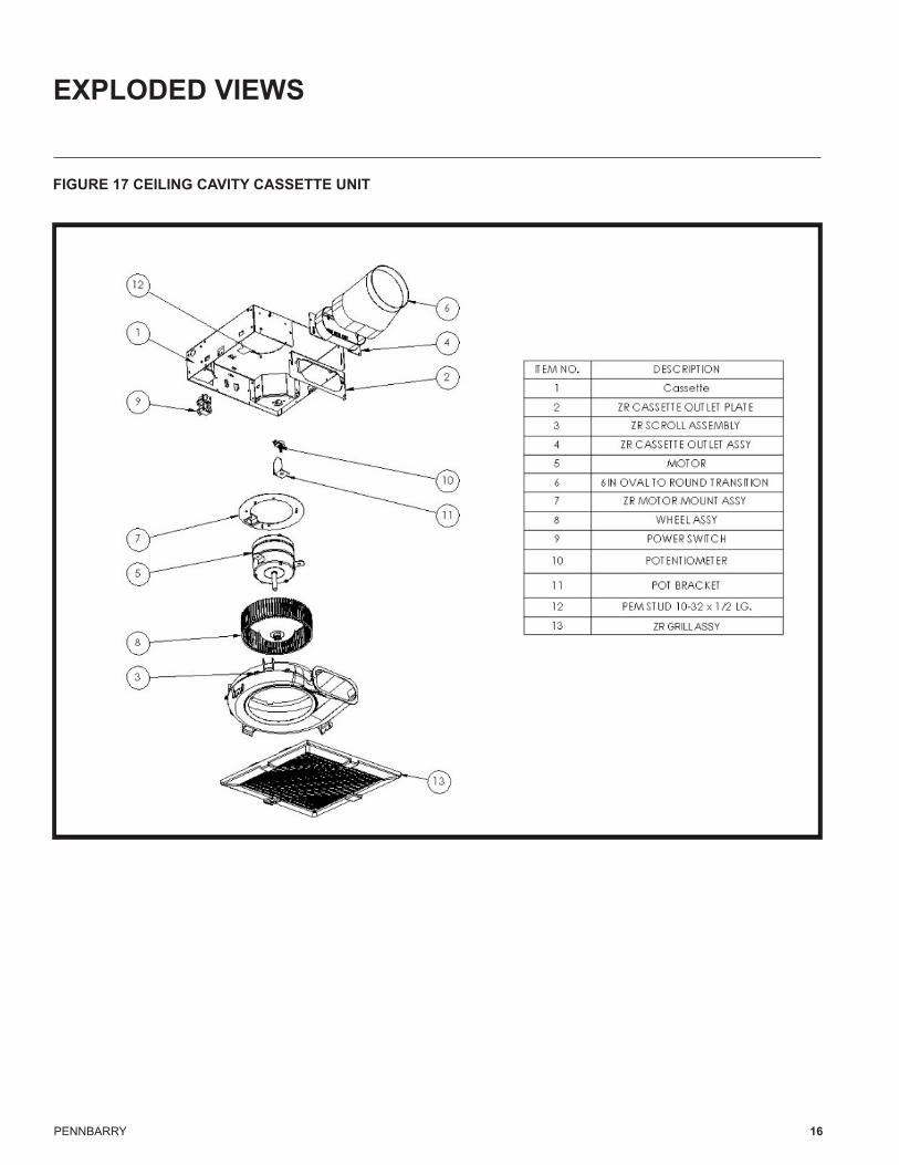
EXPLODED VIEWS
FIGURE 17 CEILING CAVITY CASSETTE UNIT
PENNBARRY 17
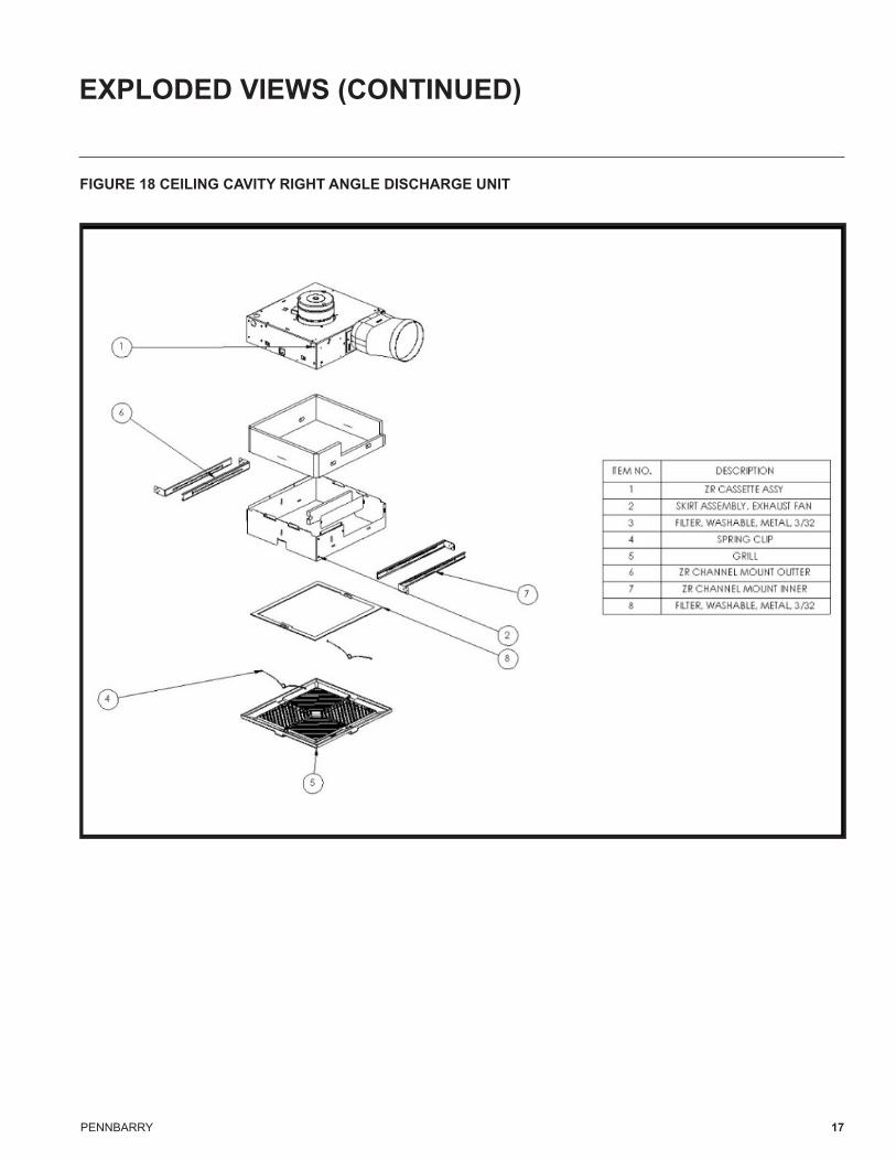
EXPLODED VIEWS (CONTINUED)
FIGURE 18 CEILING CAVITY RIGHT ANGLE DISCHARGE UNIT
PENNBARRY 18
EXPLODED VIEWS (CONTINUED)
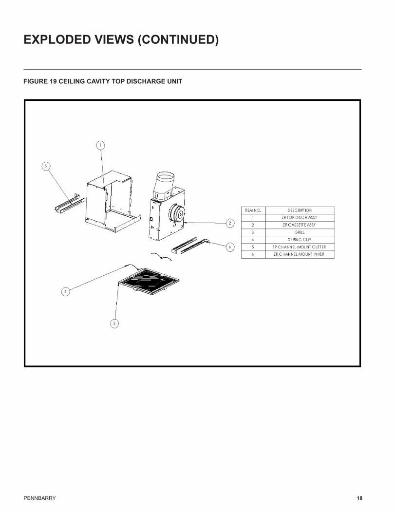
FIGURE 19 CEILING CAVITY TOP DISCHARGE UNIT
PENNBARRY 19
EXPLODED VIEWS (CONTINUED)
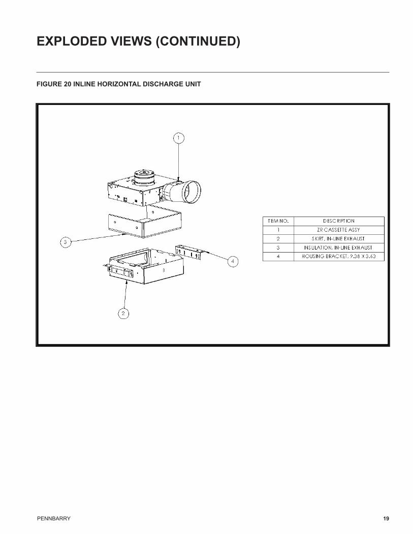
FIGURE 20 INLINE HORIZONTAL DISCHARGE UNIT
PENNBARRY 20
EXPLODED VIEWS (CONTINUED)
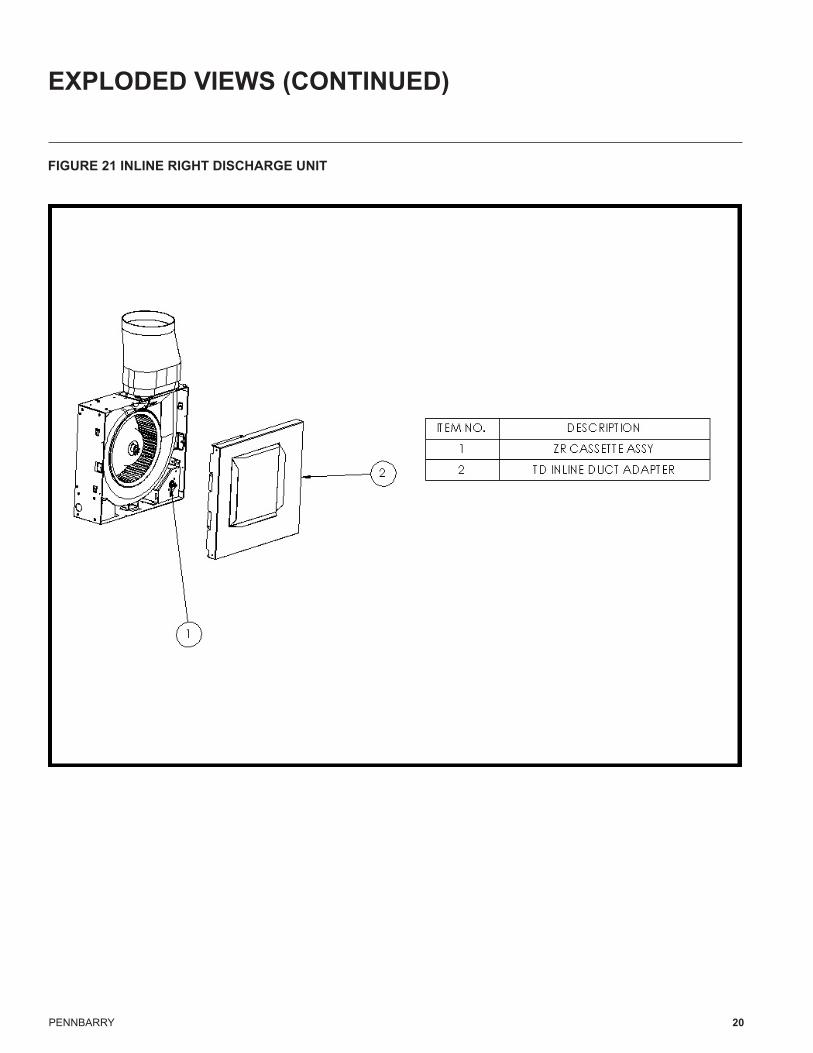
FIGURE 21 INLINE RIGHT DISCHARGE UNIT
PENNBARRY 21
EXPLODED VIEWS (CONTINUED)
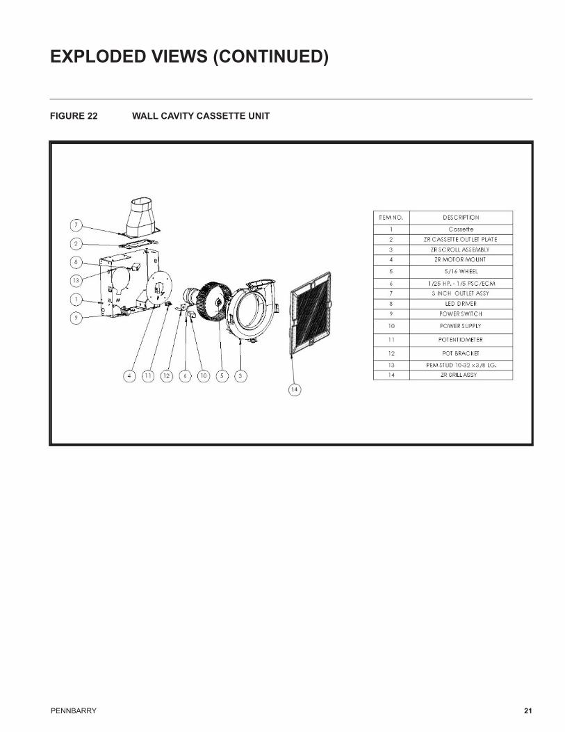
FIGURE 22 WALL CAVITY CASSETTE UNIT
PENNBARRY 22
DIMENSIONS
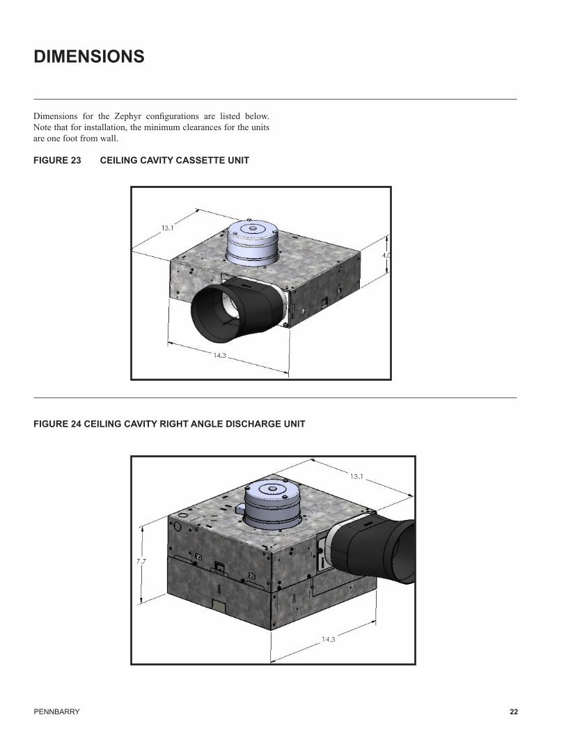
Dimensions for the Zephyr configurations are listed below. Note that for installation, the minimum clearances for the units are one foot from wall.
FIGURE 23 CEILING CAVITY CASSETTE UNIT
FIGURE 24 CEILING CAVITY RIGHT ANGLE DISCHARGE UNIT
PENNBARRY 23
DIMENSIONS (CONTINUED)
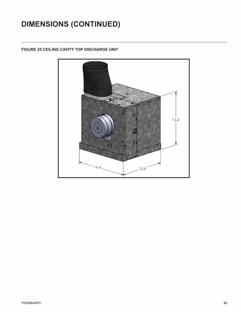
FIGURE 25 CEILING CAVITY TOP DISCHARGE UNIT
PENNBARRY 24
DIMENSIONS (CONTINUED)
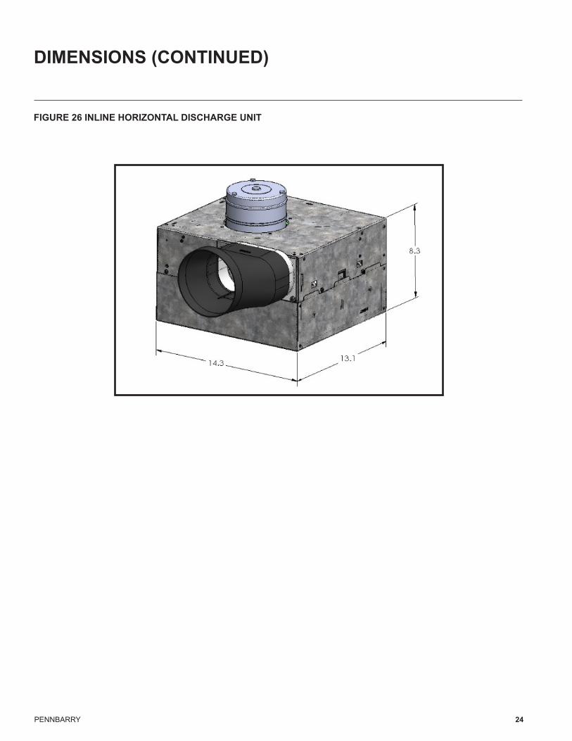
FIGURE 26 INLINE HORIZONTAL DISCHARGE UNIT

PENNBARRY 25
DIMENSIONS (CONTINUED)
FIGURE 27 INLINE RIGHT ANGLE DISCHARGE UNIT
PENNBARRY 26
DIMENSIONS (CONTINUED)
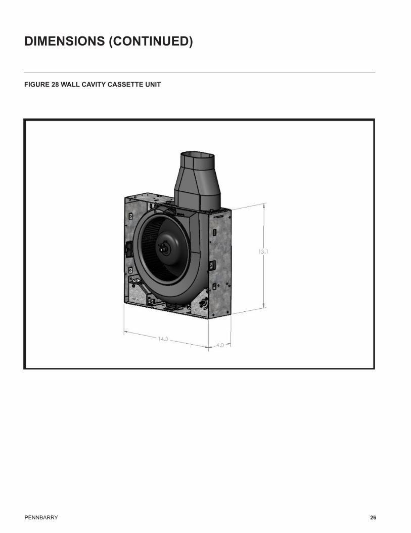
FIGURE 28 WALL CAVITY CASSETTE UNIT
PENNBARRY 27
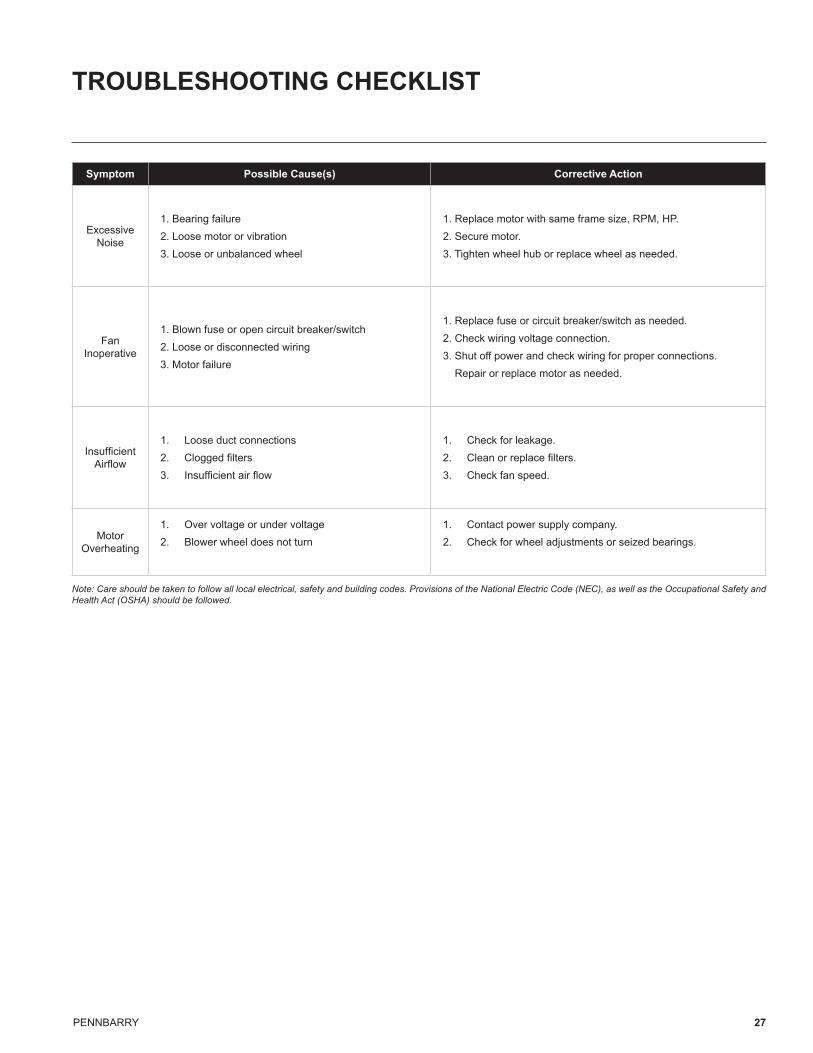
TROUBLESHOOTING CHECKLIST
Symptom Possible Cause(s) Corrective Action
Excessive Noise
1. Bearing failure2. Loose motor or vibration3. Loose or unbalanced wheel
1. Replace motor with same frame size, RPM, HP.2. Secure motor.3. Tighten wheel hub or replace wheel as needed.
Fan Inoperative
1. Blown fuse or open circuit breaker/switch2. Loose or disconnected wiring3. Motor failure
1. Replace fuse or circuit breaker/switch as needed.2. Check wiring voltage connection.3. Shut off power and check wiring for proper connections. Repair or replace motor as needed.
Insufficient Airflow
1. Loose duct connections2. Clogged filters3. Insufficient air flow
1. Check for leakage.2. Clean or replace filters.3. Check fan speed.
Motor Overheating
1. Over voltage or under voltage2. Blower wheel does not turn
1. Contact power supply company.2. Check for wheel adjustments or seized bearings.
Note: Care should be taken to follow all local electrical, safety and building codes. Provisions of the National Electric Code (NEC), as well as the Occupational Safety and Health Act (OSHA) should be followed.

PennBarry | www.pennbarry.com | [email protected] | tel: 972.212.4700 | fax: 972.212.4702 PennBarry reserves the right to make changes at any time, without notice, to models, construction, specifications, options, availability, etc. This manual illustrates the appearance of PennBarry products at the time of publication. View the latest updates on the PennBarry website.
© Copyright 2017 PennBarry. All Rights Reserved. Revised April 2017
PennBarry is proud to be your preferred manufacturer of commercial and industrial fans and blowers. Learn how PennBarry can assist you in your next application by contacting your PennBarry Representative or visiting us on the web at www.pennbarry.com.
TM


![Total No. of Questions : 3 ] [ Total No. of Printed Pages ... · 3 Total No. of Questions : 3 ] [ Total No. of Printed Pages : 2 Code No. : BFSD-10 ÃpO"@¡T"Zrb"p#–2016 {V".ï.1](https://img.pdfslide.us/doc/110x75/60d515d295c51d593c47cbef/total-no-of-questions-3-total-no-of-printed-pages-3-total-no-of-questions.jpg)
![10 Poster Program - Elsevier...6th Nano Today Conference – Poster Program [P1.30] Synthesis of one -dimensional ZrB 2 by an organic route R. Li, Beihang University, China [P2.1]](https://img.pdfslide.us/doc/110x75/5e56bc2f09a276068a4023c7/10-poster-program-elsevier-6th-nano-today-conference-a-poster-program-p130.jpg)