Embed Size (px)
Citation preview
ZENOTEC T1Operating Instructions Version 2.1
D E N T A L

ZENOTEC T1 Operating Instruction • Version 2.1 en2
Revision Historie Date Signature
1.0 en Initial version, SW: CAM 4.0 20.08.2009 DOG/Rud
2.0 en Translation of German Version 26.01.2011 DOG/Rud
2.1 en Modification mains voltage 29.04.2011 DOG/Rud
ZENOTEC T1 Operating Instruction, Version 2.1 en 3
T A B L E O F C O N T E N T S
Table of Contents
1 General information 7
1.1 Forward . . . . . . . . . . . . . . . . . . . . . . . . . . . . . . . . . . . . . . . . . . . . . . . . . . . . . . . . . . . 7
1.2 Product identification . . . . . . . . . . . . . . . . . . . . . . . . . . . . . . . . . . . . . . . . . . . . . . . . 8
1.2.1 Name of system . . . . . . . . . . . . . . . . . . . . . . . . . . . . . . . . . . . . . . . . . . . . . . . . . . . . . . 8
1.2.2 Manufacturer . . . . . . . . . . . . . . . . . . . . . . . . . . . . . . . . . . . . . . . . . . . . . . . . . . . . . . . 8
1.2.3 Proof of origin . . . . . . . . . . . . . . . . . . . . . . . . . . . . . . . . . . . . . . . . . . . . . . . . . . . . . . . 8
1.2.4 Document . . . . . . . . . . . . . . . . . . . . . . . . . . . . . . . . . . . . . . . . . . . . . . . . . . . . . . . . . . 8
1.2.5 Copyright . . . . . . . . . . . . . . . . . . . . . . . . . . . . . . . . . . . . . . . . . . . . . . . . . . . . . . . . . . 8
1.3 Type plate and CE mark . . . . . . . . . . . . . . . . . . . . . . . . . . . . . . . . . . . . . . . . . . . . . . 9
1.4 Warranty conditions . . . . . . . . . . . . . . . . . . . . . . . . . . . . . . . . . . . . . . . . . . . . . . . . 10
1.5 Composition of the operating instructions . . . . . . . . . . . . . . . . . . . . . . . . . . . . . 10
1.5.1 Basic principle . . . . . . . . . . . . . . . . . . . . . . . . . . . . . . . . . . . . . . . . . . . . . . . . . . . . . . 10
1.5.2 Definition of terms . . . . . . . . . . . . . . . . . . . . . . . . . . . . . . . . . . . . . . . . . . . . . . . . . . . 11
1.5.3 Symbols . . . . . . . . . . . . . . . . . . . . . . . . . . . . . . . . . . . . . . . . . . . . . . . . . . . . . . . . . . . 11
1.5.4 Target group . . . . . . . . . . . . . . . . . . . . . . . . . . . . . . . . . . . . . . . . . . . . . . . . . . . . . . . 12
1.5.5 Conventions used for representation . . . . . . . . . . . . . . . . . . . . . . . . . . . . . . . . . . . . . 12
1.5.6 Additional system documentation . . . . . . . . . . . . . . . . . . . . . . . . . . . . . . . . . . . . . . . 12
2 Safety instructions and warnings 13
2.1 Significance of the general safety instructions . . . . . . . . . . . . . . . . . . . . . . . . . . 13
2.1.1 Significance of the special safety instructions . . . . . . . . . . . . . . . . . . . . . . . . . . . . . . . 13
2.1.2 Legal safety instructions . . . . . . . . . . . . . . . . . . . . . . . . . . . . . . . . . . . . . . . . . . . . . . . 13
2.1.3 Consequences of nonobservance of the safety instructions . . . . . . . . . . . . . . . . . . . . 13
2.2 Designated use . . . . . . . . . . . . . . . . . . . . . . . . . . . . . . . . . . . . . . . . . . . . . . . . . . . . 14
2.2.1 Basic principle . . . . . . . . . . . . . . . . . . . . . . . . . . . . . . . . . . . . . . . . . . . . . . . . . . . . . . 14
2.2.2 Technical condition . . . . . . . . . . . . . . . . . . . . . . . . . . . . . . . . . . . . . . . . . . . . . . . . . . 14
ZENOTEC T1 Operating Instruction, Version 2.1 en 4
T A B L E O F C O N T E N T S
2.2.3 Correct use in accordance to the instructions . . . . . . . . . . . . . . . . . . . . . . . . . . . . . . . 14
2.2.4 Incorrect use not in accordance to the instructions . . . . . . . . . . . . . . . . . . . . . . . . . . . 14
2.3 General safety regulations . . . . . . . . . . . . . . . . . . . . . . . . . . . . . . . . . . . . . . . . . . . 15
2.3.1 Modification . . . . . . . . . . . . . . . . . . . . . . . . . . . . . . . . . . . . . . . . . . . . . . . . . . . . . . . 15
2.3.2 Protective equipment and safety equipment . . . . . . . . . . . . . . . . . . . . . . . . . . . . . . . 15
2.3.3 Power supply . . . . . . . . . . . . . . . . . . . . . . . . . . . . . . . . . . . . . . . . . . . . . . . . . . . . . . . 15
2.3.4 Spare parts . . . . . . . . . . . . . . . . . . . . . . . . . . . . . . . . . . . . . . . . . . . . . . . . . . . . . . . . 15
2.4 Responsibilities . . . . . . . . . . . . . . . . . . . . . . . . . . . . . . . . . . . . . . . . . . . . . . . . . . . . 16
2.4.1 Storage of system documentation . . . . . . . . . . . . . . . . . . . . . . . . . . . . . . . . . . . . . . . 16
2.4.2 Responsibilities of the operator . . . . . . . . . . . . . . . . . . . . . . . . . . . . . . . . . . . . . . . . . 16
2.4.3 Responsibilities of the operator . . . . . . . . . . . . . . . . . . . . . . . . . . . . . . . . . . . . . . . . . 16
2.4.4 Monitoring and information . . . . . . . . . . . . . . . . . . . . . . . . . . . . . . . . . . . . . . . . . . . 16
2.5 Personnel . . . . . . . . . . . . . . . . . . . . . . . . . . . . . . . . . . . . . . . . . . . . . . . . . . . . . . . . . 17
2.5.1 Regulations and work safety . . . . . . . . . . . . . . . . . . . . . . . . . . . . . . . . . . . . . . . . . . . 17
2.5.2 Requirements of the operating personnel . . . . . . . . . . . . . . . . . . . . . . . . . . . . . . . . . 17
2.5.3 Areas of responsibility . . . . . . . . . . . . . . . . . . . . . . . . . . . . . . . . . . . . . . . . . . . . . . . . 17
2.5.4 Working clothes . . . . . . . . . . . . . . . . . . . . . . . . . . . . . . . . . . . . . . . . . . . . . . . . . . . . 18
2.5.5 Personal protective equipment . . . . . . . . . . . . . . . . . . . . . . . . . . . . . . . . . . . . . . . . . . 18
2.5.6 Ergonomic work guidelines . . . . . . . . . . . . . . . . . . . . . . . . . . . . . . . . . . . . . . . . . . . . 18
2.5.7 Cleanliness at the workplace . . . . . . . . . . . . . . . . . . . . . . . . . . . . . . . . . . . . . . . . . . . 18
2.5.8 Behaviour in case of faults . . . . . . . . . . . . . . . . . . . . . . . . . . . . . . . . . . . . . . . . . . . . . 19
2.5.9 Special risks/dangers . . . . . . . . . . . . . . . . . . . . . . . . . . . . . . . . . . . . . . . . . . . . . . . . . 19
2.5.10 Dangers from electrical energy . . . . . . . . . . . . . . . . . . . . . . . . . . . . . . . . . . . . . . . . . . 19
2.5.11 Dangers from pneumatic energy . . . . . . . . . . . . . . . . . . . . . . . . . . . . . . . . . . . . . . . . 20
2.5.12 Safety system . . . . . . . . . . . . . . . . . . . . . . . . . . . . . . . . . . . . . . . . . . . . . . . . . . . . . . . 20
2.5.13 Hazard instructions specific to the product . . . . . . . . . . . . . . . . . . . . . . . . . . . . . . . . . 21
3 Description of product 23
3.1 Device models . . . . . . . . . . . . . . . . . . . . . . . . . . . . . . . . . . . . . . . . . . . . . . . . . . . . . 23
3.2 Scope of delivery . . . . . . . . . . . . . . . . . . . . . . . . . . . . . . . . . . . . . . . . . . . . . . . . . . 23
3.3 Device description . . . . . . . . . . . . . . . . . . . . . . . . . . . . . . . . . . . . . . . . . . . . . . . . . 24
ZENOTEC T1 Operating Instruction, Version 2.1 en 5
T A B L E O F C O N T E N T S
3.3.1 Functional principle . . . . . . . . . . . . . . . . . . . . . . . . . . . . . . . . . . . . . . . . . . . . . . . . . . 24
3.3.2 Spindle . . . . . . . . . . . . . . . . . . . . . . . . . . . . . . . . . . . . . . . . . . . . . . . . . . . . . . . . . . . 25
3.3.3 Suction unit . . . . . . . . . . . . . . . . . . . . . . . . . . . . . . . . . . . . . . . . . . . . . . . . . . . . . . . . 26
3.4 Technical data . . . . . . . . . . . . . . . . . . . . . . . . . . . . . . . . . . . . . . . . . . . . . . . . . . . . . 27
3.4.1 Dimensions and weight of T1 (without stack) . . . . . . . . . . . . . . . . . . . . . . . . . . . . . . . 27
3.4.2 Dimensions and weight of T1 with stack . . . . . . . . . . . . . . . . . . . . . . . . . . . . . . . . . . 27
3.4.3 Power supply . . . . . . . . . . . . . . . . . . . . . . . . . . . . . . . . . . . . . . . . . . . . . . . . . . . . . . . 28
3.4.4 Ambient conditions . . . . . . . . . . . . . . . . . . . . . . . . . . . . . . . . . . . . . . . . . . . . . . . . . . 28
4 Initial startup 29
4.1 Space requirements . . . . . . . . . . . . . . . . . . . . . . . . . . . . . . . . . . . . . . . . . . . . . . . . 29
4.2 Erection and connection of the system . . . . . . . . . . . . . . . . . . . . . . . . . . . . . . . . . 30
4.3 Erection . . . . . . . . . . . . . . . . . . . . . . . . . . . . . . . . . . . . . . . . . . . . . . . . . . . . . . . . . . 31
4.3.1 Requirements . . . . . . . . . . . . . . . . . . . . . . . . . . . . . . . . . . . . . . . . . . . . . . . . . . . . . . 31
4.4 Connecting the components . . . . . . . . . . . . . . . . . . . . . . . . . . . . . . . . . . . . . . . . . 33
4.5 Emergency-off switch . . . . . . . . . . . . . . . . . . . . . . . . . . . . . . . . . . . . . . . . . . . . . . . 34
5 Operation 35
5.1 Requirements . . . . . . . . . . . . . . . . . . . . . . . . . . . . . . . . . . . . . . . . . . . . . . . . . . . . . 35
5.2 Requirements of the operating personnel . . . . . . . . . . . . . . . . . . . . . . . . . . . . . . 35
5.3 Conventions . . . . . . . . . . . . . . . . . . . . . . . . . . . . . . . . . . . . . . . . . . . . . . . . . . . . . . 36
5.4 Overview . . . . . . . . . . . . . . . . . . . . . . . . . . . . . . . . . . . . . . . . . . . . . . . . . . . . . . . . . 36
5.5 Generating data with ZENOTEC CAM 4.0 Plus . . . . . . . . . . . . . . . . . . . . . . . . . . . 37
5.5.1 General information . . . . . . . . . . . . . . . . . . . . . . . . . . . . . . . . . . . . . . . . . . . . . . . . . 37
5.5.2 Requirements . . . . . . . . . . . . . . . . . . . . . . . . . . . . . . . . . . . . . . . . . . . . . . . . . . . . . . 37
5.6 Operation via web interface . . . . . . . . . . . . . . . . . . . . . . . . . . . . . . . . . . . . . . . . . 38
5.6.1 Overview . . . . . . . . . . . . . . . . . . . . . . . . . . . . . . . . . . . . . . . . . . . . . . . . . . . . . . . . . . 39
5.6.2 GUI . . . . . . . . . . . . . . . . . . . . . . . . . . . . . . . . . . . . . . . . . . . . . . . . . . . . . . . . . . . . . . 40
ZENOTEC T1 Operating Instruction, Version 2.1 en 6
T A B L E O F C O N T E N T S
5.7 Operation on touchpanel . . . . . . . . . . . . . . . . . . . . . . . . . . . . . . . . . . . . . . . . . . . . 52
5.7.1 Requirements . . . . . . . . . . . . . . . . . . . . . . . . . . . . . . . . . . . . . . . . . . . . . . . . . . . . . . 52
5.7.2 Conventions . . . . . . . . . . . . . . . . . . . . . . . . . . . . . . . . . . . . . . . . . . . . . . . . . . . . . . . 52
5.7.3 Overview . . . . . . . . . . . . . . . . . . . . . . . . . . . . . . . . . . . . . . . . . . . . . . . . . . . . . . . . . . 53
5.7.4 Light strip . . . . . . . . . . . . . . . . . . . . . . . . . . . . . . . . . . . . . . . . . . . . . . . . . . . . . . . . . 53
5.7.5 Safety instructions for start up . . . . . . . . . . . . . . . . . . . . . . . . . . . . . . . . . . . . . . . . . . 53
5.7.6 Switch on the machine . . . . . . . . . . . . . . . . . . . . . . . . . . . . . . . . . . . . . . . . . . . . . . . 54
5.7.7 Read-in blanks via RFI scanner . . . . . . . . . . . . . . . . . . . . . . . . . . . . . . . . . . . . . . . . . . 58
5.7.8 Tools and tool tray . . . . . . . . . . . . . . . . . . . . . . . . . . . . . . . . . . . . . . . . . . . . . . . . . . . 69
5.7.9 Job management . . . . . . . . . . . . . . . . . . . . . . . . . . . . . . . . . . . . . . . . . . . . . . . . . . . . 77
5.7.10 Service mode . . . . . . . . . . . . . . . . . . . . . . . . . . . . . . . . . . . . . . . . . . . . . . . . . . . . . . . 82
6 Faults 91
6.1 Remedying faults . . . . . . . . . . . . . . . . . . . . . . . . . . . . . . . . . . . . . . . . . . . . . . . . . . 92
6.2 Error messages on the touchpanel . . . . . . . . . . . . . . . . . . . . . . . . . . . . . . . . . . . . 95
6.3 FAQ / Frequently Asked Questions . . . . . . . . . . . . . . . . . . . . . . . . . . . . . . . . . . . 103
7 Cleaning 105
7.1 General information . . . . . . . . . . . . . . . . . . . . . . . . . . . . . . . . . . . . . . . . . . . . . . . 105
7.2 Using cleaning agents . . . . . . . . . . . . . . . . . . . . . . . . . . . . . . . . . . . . . . . . . . . . . 105
7.3 General cleanliness . . . . . . . . . . . . . . . . . . . . . . . . . . . . . . . . . . . . . . . . . . . . . . . . 106
8 Maintenance 109
8.1 Checklist . . . . . . . . . . . . . . . . . . . . . . . . . . . . . . . . . . . . . . . . . . . . . . . . . . . . . . . . 109
9 Repairs 111
ZENOTEC T1 Operating Instruction, Version 2.1 en 7
GENERAL INFORMATION
11 General information
1.1 Forward
Dear Customer
Many thanks for the trust you have placed in us by choosing the ZENOTEC T1 dental milling machine.
The concept and design of the ZENOTEC T1 are state-of-the-art.
Exhaustive training of the operating personnel by our experts is a requirement to be able to fully exploit the full range of functions of the milling machine and to ensure that it is constantly ready for operation. This also simultaneously ensures the system is available constantly.
These operating instructions are both training document and work of reference. They should always be accessible to the operating personnel. You should therefore keep the operating instruc-tions in an easily accessible location near to the system.
About us ...
We are grateful for any suggestions for improvement and all constructive ideas. We view your feedback as an important contribution to the optimal design of the ZENOTEC T1 and its concom-itant documentation. If you have any questions, please contact a consultant at WIELAND Dental + Technik GmbH & Co. KG directly:
WIELAND Dental + Technik GmbH & Co. KG
Schwenninger Straße 13
75179 Pforzheim
Germany
ZENOTEC Support
National call: 08 00 / 93 66 823
International call: +49 72 31 / 37 05 400
Fax: 0 72 31 / 35 79 59
E-mail: [email protected]
www.wieland-dental.de
ZENOTEC T1 Operating Instruction, Version 2.1 en 8
GENERAL INFORMATION
11.2 Product identification
1.2.1 Name of system
Dental milling system: ZENOTEC T1 System
1.2.2 Manufacturer
WIELAND Dental + Technik GmbH & Co. KG
Schwenninger Straße 13
75179 Pforzheim
Germany
1.2.3 Proof of origin
The ZENOTEC T1 system has been designed and produced in Germany.
1.2.4 Document
Operating instructions for the ZENOTEC T1 system.
Publication April 2011, Version 2.1
This manual has been written taking into consideration the EU Machine Directive 42/2006, Annex 1, Number 1,7.4 "Operating Instructions".
Documentation and design:
DOGREL AG, Widnau, Switzerland
1.2.5 Copyright
All rights reserved. This manual must not be copied in whole or part, photocopied, reproduced, translated or converted into an electronic or machine-readable format without the express written permission of WIELAND Dental + Technik GmbH & Co. KG.
ZENOTEC T1 Operating Instruction, Version 2.1 en 9
GENERAL INFORMATION
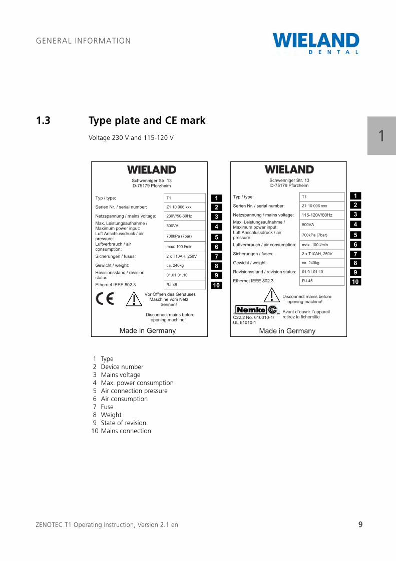
11.3 Type plate and CE mark
Voltage 230 V and 115-120 V
1 Type2 Device number3 Mains voltage4 Max. power consumption5 Air connection pressure6 Air consumption7 Fuse8 Weight9 State of revision10 Mains connection
Schwenniger Str. 13 D-75179 Pforzheim
Typ / type: T1
Serien Nr. / serial number: Z1 10 006 xxx
Netzspannung / mains voltage: Max. Leistungsaufnahme /
Maximum power input: 500VA
Luft Anschlussdruck / air pressure: 700kPa (7bar)
Luftverbrauch / air consumption: max. 100 l/min
Sicherungen / fuses: 2 x T10AH, 250V
Gewicht / weight: ca. 240kg
Revisionsstand / revision status: 01.01.01.10
Ethernet IEEE 802.3 RJ-45
C22.2 No. 610010-1/ UL 61010-1
Disconnect mains before opening machine!
Avant d`ouvrir I´appareil retirez la fichemâle
Made in Germany
115-120V/60Hz
12345678910
Schwenniger Str. 13 D-75179 Pforzheim
Typ / type: T1
Serien Nr. / serial number: Z1 10 006 xxx
Netzspannung / mains voltage: 230V/50-60Hz
Max. Leistungsaufnahme / Maximum power input: 500VA
Luft Anschlussdruck / air pressure: 700kPa (7bar)
Luftverbrauch / air consumption: max. 100 l/min
Sicherungen / fuses: 2 x T10AH, 250V
Gewicht / weight: ca. 240kg
Revisionsstand / revision status: 01.01.01.10
Ethernet IEEE 802.3 RJ-45
Vor Öffnen des Gehäuses Maschine vom Netz trennen!
Disconnect mains before opening machine!
Made in Germany
12345678910
ZENOTEC T1 Operating Instruction, Version 2.1 en 10
GENERAL INFORMATION
11.4 Warranty conditions
Warranty and liability
Warranty and guarantee are based on the conditions set in the contract. All warranties and condi-tions set in the contract must be kept together with these operating instructions. Changes to the system or its protective equipment are forbidden. If repairs or maintenance are required then WIELAND Dental + Technik GmbH & Co. KG must be informed and contracted accordingly. Any changes made to the system without the knowledge and approval of WIELAND Dental + Technik GmbH & Co. KG invalidate all warranty and liability claims.
Disposal
Disposal compliant to the electrical and electronic device law is based on the conditions set in the contract.
1.5 Composition of the operating instructions
1.5.1 Basic principle
We want to help you to be able to operate, maintain and repair the ZENOTEC T1 system as quickly, efficiently and professionally as possible. This also means you are able to find your way around the operating instructions!
Further developments for our customers require continuous reworking and adjustment of the operating instructions. These operating instructions are therefore not transferrable to other systems within this model series. To ensure that the operating instructions remain complete at all times and accord to the current state of technology, do not remove any single documents from it.
Current versions of the operating instructions are located at the internet page of WIELAND Dental + Technik GmbH & Co. KG as follows:
http://www.wieland-dental.de/service/download-center/
ZENOTEC T1 Operating Instruction, Version 2.1 en 11
GENERAL INFORMATION
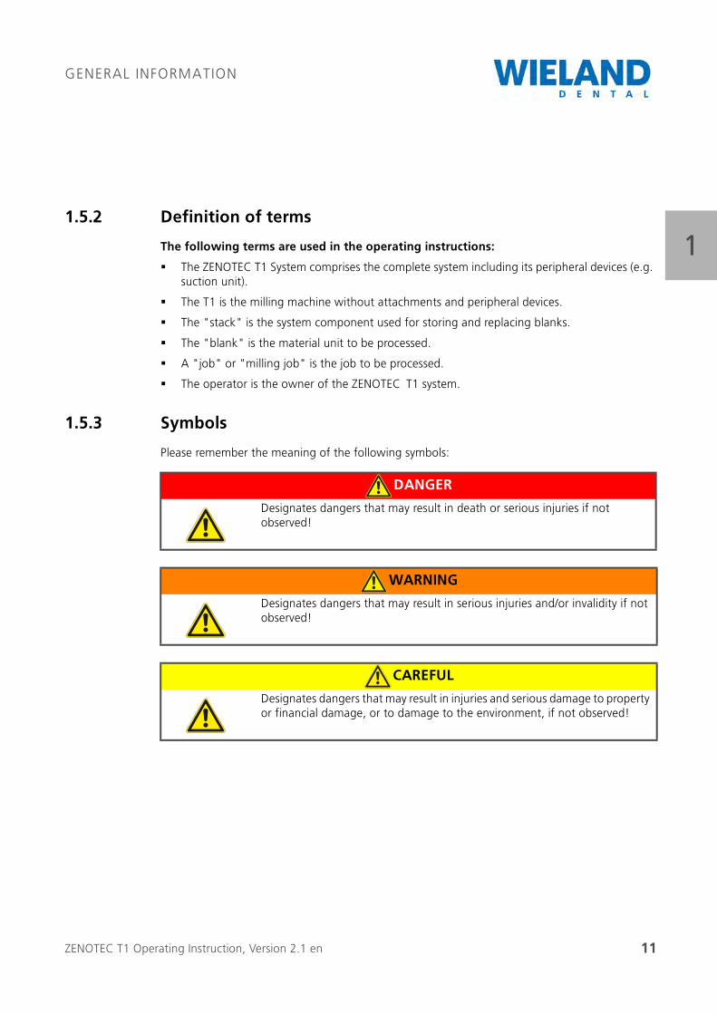
11.5.2 Definition of terms
The following terms are used in the operating instructions:
The ZENOTEC T1 System comprises the complete system including its peripheral devices (e.g. suction unit).
The T1 is the milling machine without attachments and peripheral devices.
The "stack" is the system component used for storing and replacing blanks.
The "blank" is the material unit to be processed.
A "job" or "milling job" is the job to be processed.
The operator is the owner of the ZENOTEC T1 system.
1.5.3 Symbols
Please remember the meaning of the following symbols:
DANGER
Designates dangers that may result in death or serious injuries if not observed!
WARNING
Designates dangers that may result in serious injuries and/or invalidity if not observed!
CAREFUL
Designates dangers that may result in injuries and serious damage to property or financial damage, or to damage to the environment, if not observed!
ZENOTEC T1 Operating Instruction, Version 2.1 en 12
GENERAL INFORMATION
11.5.4 Target group
All work with and at the ZENOTEC T1 may only be carried out by trained and instructed personnel. A recognised technical course of training and knowledge gained therein of normal technical processes is assumed. The personnel must read and understand the operating instructions.
The operator of the system is responsible for the selection, instruction and checking of the personnel.
1.5.5 Conventions used for representation
The following conventions are used for representation in these operating instructions:
Bold to stress a word/words or for paragraph headings
Letters in brackets after terms used as reference to positions in pictures.
For example: "...select from "submenu" (D)..."
1.5.6 Additional system documentation
The following documents also exist in addition to the operating instructions for the ZENOTEC T1 System:
Warranty conditions
Installation instructions
Repair instructions
ZENOTEC CAM 4.0 Plus operating instructions (when included in the delivery)
Original operating instructions of the spindle manufacturer (Jäger)

ZENOTEC T1 Operating Instruction, Version 2.1 en 13
SAFETY INSTRUCTIONS AND WARNINGS
22 Safety instructions and warnings
The ZENOTEC T1 System is subjected to a post-production quality check. The system is assembled and its functions are checked before being handed over. The function of the safety equipment is additionally checked. Nevertheless, residual dangers may still apply to the dental milling machine. The “Safety instructions” chapter must therefore be read. The following general safety instruc-tions are supplemented by special safety instructions in the respective chapters.
2.1 Significance of the general safety instructions
The general safety instructions contained in this chapter inform you of possible residual dangers that still exist or may unexpectedly arise from the ZENOTEC T1 System even when used correctly and in accordance to the instructions. To prevent injuries to persons as well as damage to property and the environment, the safety instructions must be observed by all persons working on or at the ZENOTEC T1 System. Reading and understanding this chapter is therefore compulsory for these persons.
2.1.1 Significance of the special safety instructions
Safety instructions that apply in certain situations are provided at the appropriate locations in the operating instructions. These instructions are compulsory and must be observed to protect persons, property and the environment.
2.1.2 Legal safety instructions
In addition to the safety instructions in these operating instructions, the valid legal regulations on accident-prevention and environmental protection applicable in the country and location at which the ZENOTEC T1 System is used must be observed. The recognised technical regulations regarding safety and correct work must also be observed
2.1.3 Consequences of nonobservance of the safety instructions
Nonobservance of the safety instructions may result in accidents with serious injuries to persons and damage to property and the environment.
The manufacturer is not liable for any damages caused by nonobservance of the safety instructions.
ZENOTEC T1 Operating Instruction, Version 2.1 en 14
SAFETY INSTRUCTIONS AND WARNINGS
22.2 Designated use
2.2.1 Basic principle
The ZENOTEC T1 System may only be operated in a technically perfect condition in full accordance to the instructions taking into consideration all safety and danger requirements and in full obser-vance of these operating instructions. Nevertheless, dangers may arise for persons, material and the environment when operating the machine.
2.2.2 Technical condition
Operational malfunctions as well as defects, especially those that may impair the safety of the ZENOTEC T1 System, must be remedied immediately. In case of faults and defects, WIELAND Dental + Technik GmbH & Co. KG must be informed immediately. Additionally, the ZENOTEC T1 System must be immediately put out of operation until the fault or defect has been completely removed/remedied.
2.2.3 Correct use in accordance to the instructions
The ZENOTEC T1 System is exclusively intended for the milling of dental prostheses. The tech-nical data in Chapter «3.4 Technical data» list the binding limits of use and the features of the machine. Correct use in accordance to the instructions also includes observance of the instructions in these operating instructions and observance of the inspection and maintenance work, as well as the required qualifications of the personnel working at the machine. Any and all other use is deemed as improper and not in accordance to the instructions. The manufacturer is not liable for any damages arising therefrom! This risk is borne fully by the operator!
2.2.4 Incorrect use not in accordance to the instructions
Milling other materials than those recommended by Wieland
Carrying out repairs without the written authorization of WIELAND Dental + Technik GmbH & Co. KG
Use of accessories or spare parts from other manufacturers
Starting up the ZENOTEC T1 System without authorization
Starting up the ZENOTEC T1 System without instruction

ZENOTEC T1 Operating Instruction, Version 2.1 en 15
SAFETY INSTRUCTIONS AND WARNINGS
2If the machine is used incorrectly and not observing the instructions, there is a risk/danger of:
Injury to persons
Damage to the machine
Damage to the product being processed as well as other damages
Malfunction of the ZENOTEC T1 System
2.3 General safety regulations
2.3.1 Modification
Modifications to the milling system are never permitted. Addition of attachments and retrofitting is always to be carried out by WIELAND Dental + Technik GmbH & Co. KG. The adjustments required in the operating instructions in such a case are made by the manufacturer.
2.3.2 Protective equipment and safety equipment
The protective and safety equipment attached to the ZENOTEC T1 milling system may neither be removed nor put out of operation during normal operation. In special operation, such as during startup, maintenance and repairs,WIELAND Dental + Technik GmbH & Co. KG must be informed. The removal of the protective and safety equipment that is necessary for this may only be done under full observance of all necessary safety measures.
Normal operation may only be switched back on after a complete check of the safety equipment for its correct functionality.
The safety equipment includes:
Cover of the T1 milling machine
The stack cover (optional)
The emergency-off switch
The cover and connections for energy and the pneumatics
2.3.3 Power supply
The power ratings on the type plate and in the "Product description" chapter are binding for the power connection. The power supply can be switched off on the unit by the emergency-off switch. The switch-off device is clearly marked.
ZENOTEC T1 Operating Instruction, Version 2.1 en 16
SAFETY INSTRUCTIONS AND WARNINGS
22.3.4 Spare parts
Only spare parts specified by the manufacturer may be used
2.4 Responsibilities
2.4.1 Storage of system documentation
The operating instructions must always be kept within reach of all persons working on the ZENOTEC T1 system. The location at which the operating instructions are stored must be clearly marked by the operator. Additional folders with the spare parts documentation and manufac-turer's documents must be accessible to the maintenance and service personnel of WIELAND Dental + Technik GmbH & Co. KG.
2.4.2 Responsibilities of the operator
WIELAND Dental + Technik GmbH & Co. KG is responsible for product safety. It thereby transfers important responsibilities to the operator.
2.4.3 Responsibilities of the operator
Training and responsibilities
The operator ensures that all activities at the ZENOTEC System are only carried out by authorised persons. He carries out a thorough course of training of all persons active at the milling system, even those who only work at it for a short time. This course pays special attention to the residual risks/dangers and the safety instructions based on these operating instructions. The operator thereby sets clearly defined responsibilities.
Instruction in case of dangers
The operator ensures that his personnel has been instructed regarding all existing residual dangers and that work is only carried out at the ZENOTEC T1 System in compliance to these operating instructions. He ensures that all relevant safety aids/extras are available for the course of instruc-tion.
Maintenance obligation and due diligence
The operator ensures that the ZENOTEC T1 system is kept and operated in a perfect technical condition. If repairs are necessary then the operator informs WIELAND Dental + Technik GmbH & Co. KG of this.
ZENOTEC T1 Operating Instruction, Version 2.1 en 17
SAFETY INSTRUCTIONS AND WARNINGS
22.4.4 Monitoring and information
The operator is obliged to immediately report all (residual) danger and risks noticed during oper-ation that are not described in these operating instructions to the manufacturer.
Any conditions and/or measures ordered by the manufacturer based on such a report must be complied with by the operator.
2.5 Personnel
2.5.1 Regulations and work safety
Without exception, the local safety and accident-prevention regulations always apply for opera-tion of the ZENOTECT1 System. The protective covers must be checked every time before startup.
The operator/user must refrain from any mode of work that may impair the safety of the milling system!
All maintenance and repair work must only be carried out by the staff of WIELAND Dental + Technik GmbH & Co. KG. The system must be switched off during such work.
Independent retrofitting, maintenance work and changes are not permitted!
2.5.2 Requirements of the operating personnel
Each and every person concerned with the startup and operation of the milling system must
be appropriately trained and instructed for the activity at hand
and must have read and understood the operating instructions, especially the “Safety instruc-tions” and "Operating the system" chapters.
Personnel to be trained may only work at the milling system under supervision from an experi-enced person.
2.5.3 Areas of responsibility
WIELAND Dental + Technik GmbH & Co. KG is responsible for the perfect condition of the deliv-ered ZENOTEC T1 System with regard to its safety, including the operating instructions and the delivered accessories and spare parts. The operator is responsible for the
correct use in accordance to the instructions of the system,
training of the personnel,
provision of required protective equipment,
check that only authorised persons work at the system.
ZENOTEC T1 Operating Instruction, Version 2.1 en 18
SAFETY INSTRUCTIONS AND WARNINGS
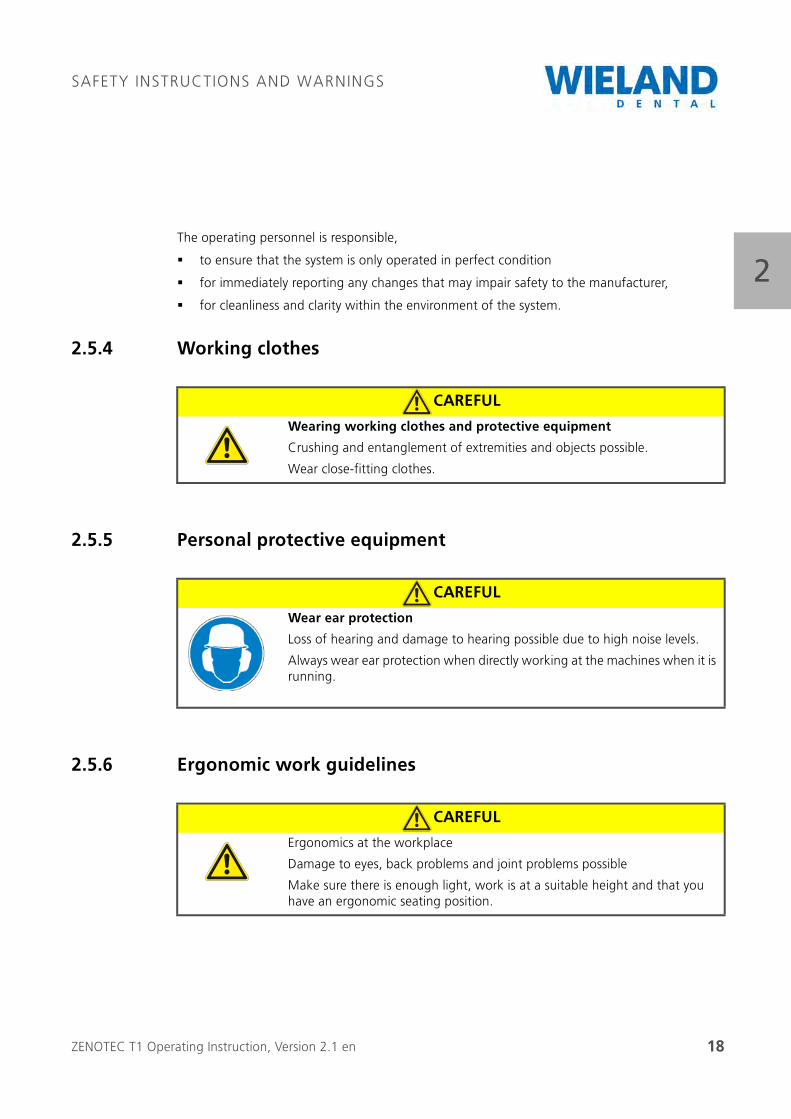
2The operating personnel is responsible,
to ensure that the system is only operated in perfect condition
for immediately reporting any changes that may impair safety to the manufacturer,
for cleanliness and clarity within the environment of the system.
2.5.4 Working clothes
2.5.5 Personal protective equipment
2.5.6 Ergonomic work guidelines
CAREFUL
Wearing working clothes and protective equipment
Crushing and entanglement of extremities and objects possible.
Wear close-fitting clothes.
CAREFUL
Wear ear protection
Loss of hearing and damage to hearing possible due to high noise levels.
Always wear ear protection when directly working at the machines when it is running.
CAREFUL
Ergonomics at the workplace
Damage to eyes, back problems and joint problems possible
Make sure there is enough light, work is at a suitable height and that you have an ergonomic seating position.
ZENOTEC T1 Operating Instruction, Version 2.1 en 19
SAFETY INSTRUCTIONS AND WARNINGS
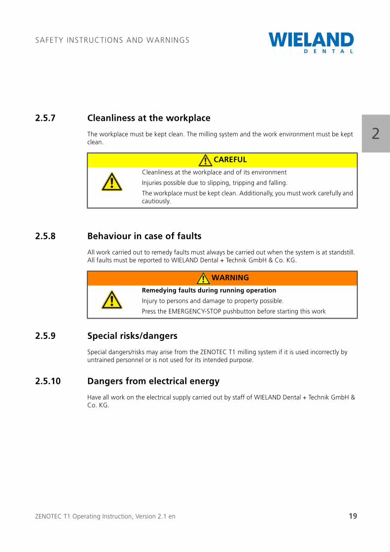
22.5.7 Cleanliness at the workplace
The workplace must be kept clean. The milling system and the work environment must be kept clean.
2.5.8 Behaviour in case of faults
All work carried out to remedy faults must always be carried out when the system is at standstill. All faults must be reported to WIELAND Dental + Technik GmbH & Co. KG.
2.5.9 Special risks/dangers
Special dangers/risks may arise from the ZENOTEC T1 milling system if it is used incorrectly by untrained personnel or is not used for its intended purpose.
2.5.10 Dangers from electrical energy
Have all work on the electrical supply carried out by staff of WIELAND Dental + Technik GmbH & Co. KG.
CAREFUL
Cleanliness at the workplace and of its environment
Injuries possible due to slipping, tripping and falling.
The workplace must be kept clean. Additionally, you must work carefully and cautiously.
WARNING
Remedying faults during running operation
Injury to persons and damage to property possible.
Press the EMERGENCY-STOP pushbutton before starting this work
ZENOTEC T1 Operating Instruction, Version 2.1 en 20
SAFETY INSTRUCTIONS AND WARNINGS
2
2.5.11 Dangers from pneumatic energy
Have all work on the pneumatic supply carried out by staff of WIELAND Dental + Technik GmbH & Co. KG.
WARNING
Open electrical connections
Lethal or severe injuries possible
If
plug connections become loose,
there are damages
or mechanical and thermal loads
then switch off the system and inform the manufacturer immediately.
WARNING
Open pneumatic connections
Serious injury to persons possible
If pneumatic connections become loose then switch off the system and immediately inform the manufacturer.
ZENOTEC T1 Operating Instruction, Version 2.1 en 21
SAFETY INSTRUCTIONS AND WARNINGS
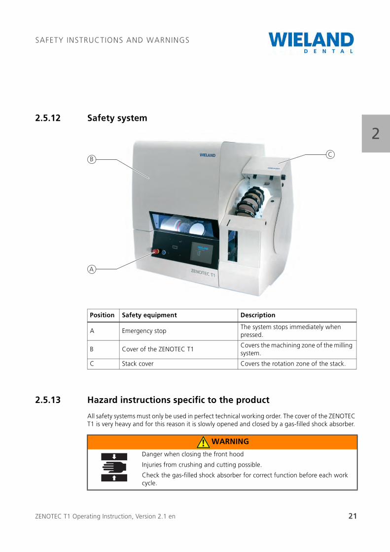
22.5.12 Safety system
2.5.13 Hazard instructions specific to the product
All safety systems must only be used in perfect technical working order. The cover of the ZENOTEC T1 is very heavy and for this reason it is slowly opened and closed by a gas-filled shock absorber.
Position Safety equipment Description
A Emergency stopThe system stops immediately when pressed.
B Cover of the ZENOTEC T1Covers the machining zone of the milling system.
C Stack cover Covers the rotation zone of the stack.
B
A
C
WARNING
Danger when closing the front hood
Injuries from crushing and cutting possible.
Check the gas-filled shock absorber for correct function before each work cycle.
ZENOTEC T1 Operating Instruction, Version 2.1 en 22
SAFETY INSTRUCTIONS AND WARNINGS
2The stack cover covers the rotation zone and protects from injuries caused by crushing and cutting.
Uncontrolled restarting of machine
WARNING
Danger when closing the stack cover
Injuries caused by crushing and cutting possible when closed incorrectly.
Do not use the cover incorrectly.
Uncontrolled restarting after interruption of the power supply.
If the power supply to the machine is interrupted then the machine must be restarted.
ZENOTEC T1 Operating Instruction, Version 2.1 en 23
DESCRIPTION OF PRODUCT
33 Description of product
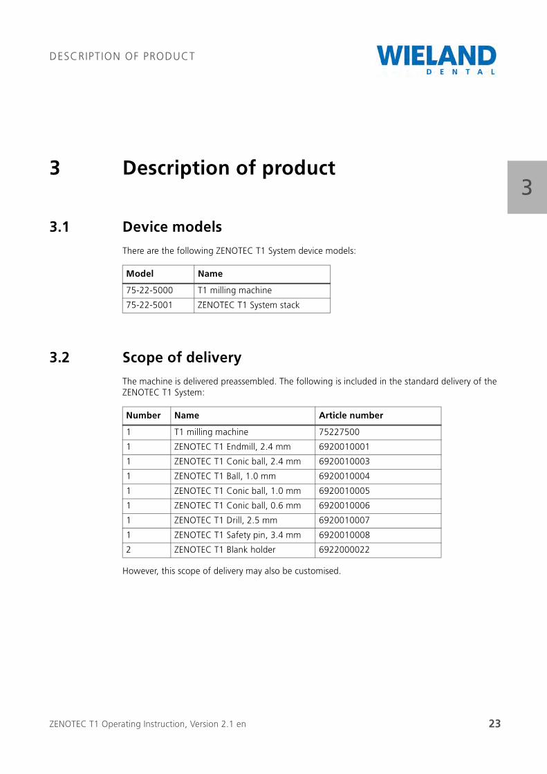
3.1 Device models
There are the following ZENOTEC T1 System device models:
3.2 Scope of delivery
The machine is delivered preassembled. The following is included in the standard delivery of the ZENOTEC T1 System:
However, this scope of delivery may also be customised.
Model Name
75-22-5000 T1 milling machine
75-22-5001 ZENOTEC T1 System stack
Number Name Article number
1 T1 milling machine 75227500
1 ZENOTEC T1 Endmill, 2.4 mm 6920010001
1 ZENOTEC T1 Conic ball, 2.4 mm 6920010003
1 ZENOTEC T1 Ball, 1.0 mm 6920010004
1 ZENOTEC T1 Conic ball, 1.0 mm 6920010005
1 ZENOTEC T1 Conic ball, 0.6 mm 6920010006
1 ZENOTEC T1 Drill, 2.5 mm 6920010007
1 ZENOTEC T1 Safety pin, 3.4 mm 6920010008
2 ZENOTEC T1 Blank holder 6922000022
ZENOTEC T1 Operating Instruction, Version 2.1 en 24
DESCRIPTION OF PRODUCT
33.3 Device description
3.3.1 Functional principle
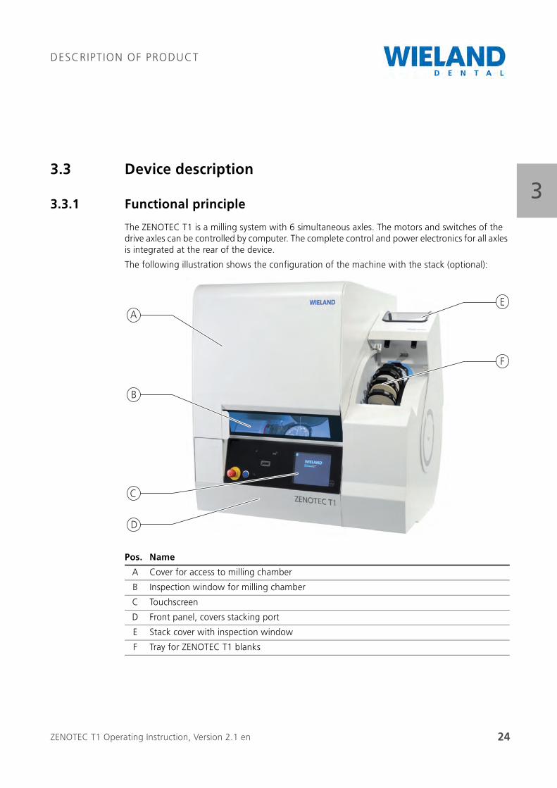
The ZENOTEC T1 is a milling system with 6 simultaneous axles. The motors and switches of the drive axles can be controlled by computer. The complete control and power electronics for all axles is integrated at the rear of the device.
The following illustration shows the configuration of the machine with the stack (optional):
Pos. Name
A Cover for access to milling chamber
B Inspection window for milling chamber
C Touchscreen
D Front panel, covers stacking port
E Stack cover with inspection window
F Tray for ZENOTEC T1 blanks
A
B
C
D
E
F
ZENOTEC T1 Operating Instruction, Version 2.1 en 25
DESCRIPTION OF PRODUCT
33.3.2 Spindle
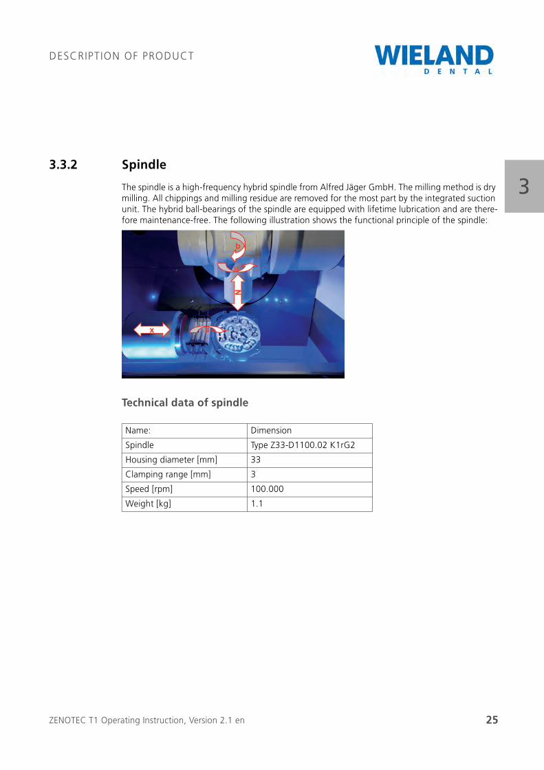
The spindle is a high-frequency hybrid spindle from Alfred Jäger GmbH. The milling method is dry milling. All chippings and milling residue are removed for the most part by the integrated suction unit. The hybrid ball-bearings of the spindle are equipped with lifetime lubrication and are there-fore maintenance-free. The following illustration shows the functional principle of the spindle:
Technical data of spindle
Name: Dimension
Spindle Type Z33-D1100.02 K1rG2
Housing diameter [mm] 33
Clamping range [mm] 3
Speed [rpm] 100.000
Weight [kg] 1.1
ZENOTEC T1 Operating Instruction, Version 2.1 en 26
DESCRIPTION OF PRODUCT
33.3.3 Suction unit
The ZENOTEC Air+ single-user suction unit is equipped with a high-pressure blower and a poten-tiometer for suction-air volume regulation. The air volume therefore remains constant by means of electronic control until the automatic switch-off device triggers. The suction unit is also equipped with a filter replacement and service indicator.
Function
The dust is collected in a two-layer disposable filter dust bag. Depending on the type of dust, it has a capacity of up to 10 kg. The large fine filter connected downstream from the disposable filter bag has a maximum transmittance of less than 0.1 %.
When using the central suction unit in place of the ZENOTEC Air+, always make sure that the suction unit has a minimum suction power of 60 l/min.
ZENOTEC T1 Operating Instruction, Version 2.1 en 27
DESCRIPTION OF PRODUCT
33.4 Technical data
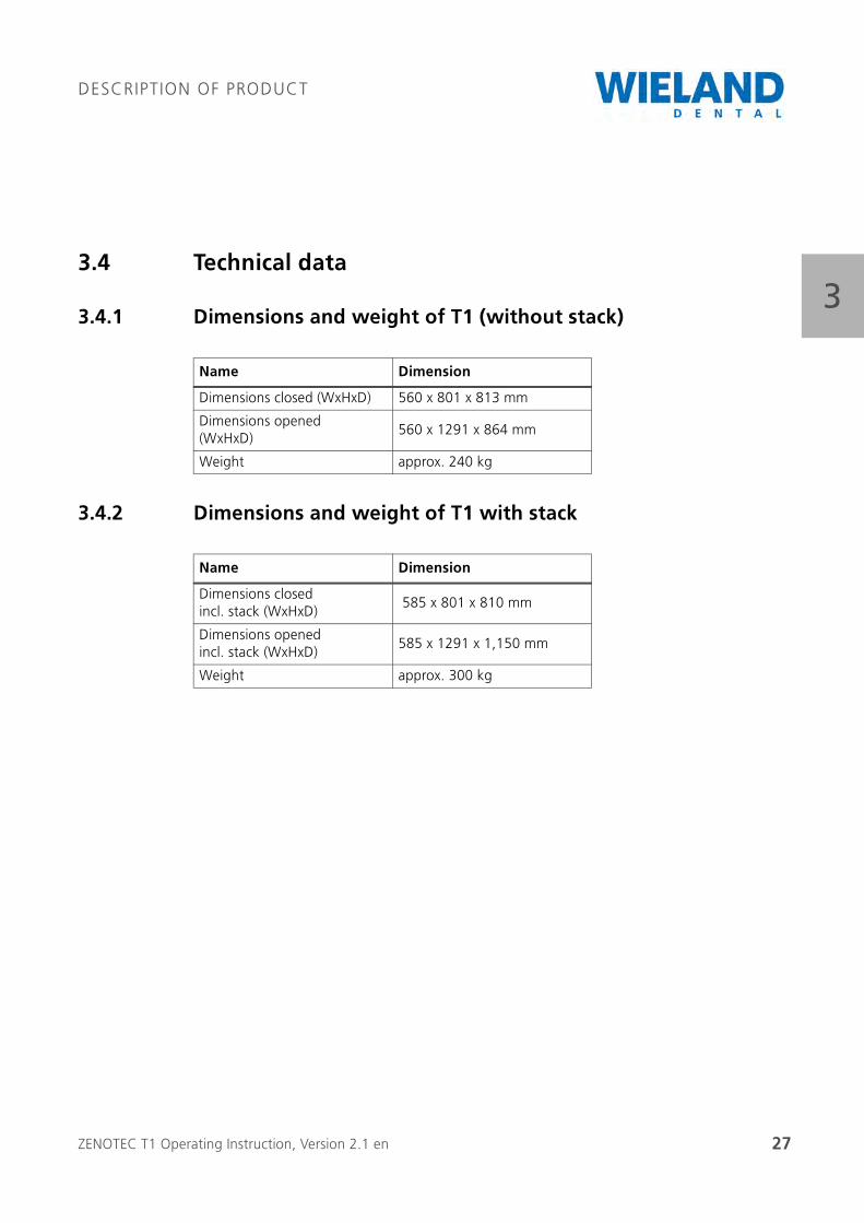
3.4.1 Dimensions and weight of T1 (without stack)
3.4.2 Dimensions and weight of T1 with stack
Name Dimension
Dimensions closed (WxHxD) 560 x 801 x 813 mm
Dimensions opened (WxHxD)
560 x 1291 x 864 mm
Weight approx. 240 kg
Name Dimension
Dimensions closed incl. stack (WxHxD)
585 x 801 x 810 mm
Dimensions opened incl. stack (WxHxD)
585 x 1291 x 1,150 mm
Weight approx. 300 kg
ZENOTEC T1 Operating Instruction, Version 2.1 en 28
DESCRIPTION OF PRODUCT
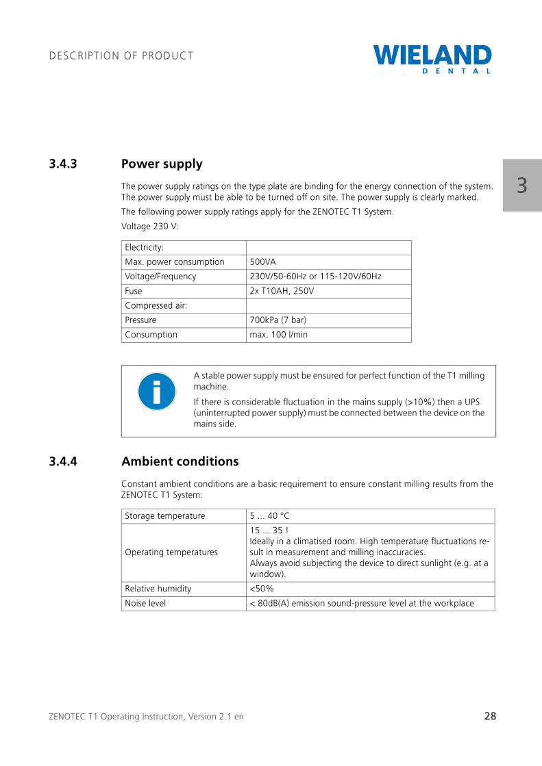
33.4.3 Power supply
The power supply ratings on the type plate are binding for the energy connection of the system. The power supply must be able to be turned off on site. The power supply is clearly marked.
The following power supply ratings apply for the ZENOTEC T1 System.
Voltage 230 V:
3.4.4 Ambient conditions
Constant ambient conditions are a basic requirement to ensure constant milling results from the ZENOTEC T1 System:
Electricity:
Max. power consumption 500VA
Voltage/Frequency 230V/50-60Hz or 115-120V/60Hz
Fuse 2x T10AH, 250V
Compressed air:
Pressure 700kPa (7 bar)
Consumption max. 100 l/min
A stable power supply must be ensured for perfect function of the T1 milling machine.
If there is considerable fluctuation in the mains supply (>10%) then a UPS (uninterrupted power supply) must be connected between the device on the mains side.
Storage temperature 5 ... 40 °C
Operating temperatures
15 ... 35 !Ideally in a climatised room. High temperature fluctuations re-sult in measurement and milling inaccuracies.Always avoid subjecting the device to direct sunlight (e.g. at a window).
Relative humidity <50%
Noise level < 80dB(A) emission sound-pressure level at the workplace
ZENOTEC T1 Operating Instruction, Version 2.1 en 29
INITIAL STARTUP
44 Initial startup
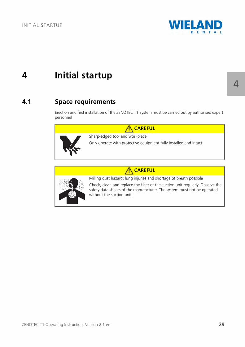
4.1 Space requirements
Erection and first installation of the ZENOTEC T1 System must be carried out by authorised expert personnel
CAREFUL
Sharp-edged tool and workpiece
Only operate with protective equipment fully installed and intact
CAREFUL
Milling dust hazard: lung injuries and shortage of breath possible
Check, clean and replace the filter of the suction unit regularly. Observe the safety data sheets of the manufacturer. The system must not be operated without the suction unit.
ZENOTEC T1 Operating Instruction, Version 2.1 en 30
INITIAL STARTUP
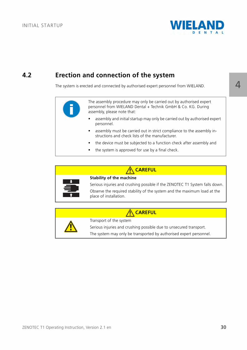
44.2 Erection and connection of the system
The system is erected and connected by authorised expert personnel from WIELAND.
The assembly procedure may only be carried out by authorised expert personnel from WIELAND Dental + Technik GmbH & Co. KG. During assembly, please note that:
assembly and initial startup may only be carried out by authorised expert personnel.
assembly must be carried out in strict compliance to the assembly in-structions and check lists of the manufacturer.
the device must be subjected to a function check after assembly and
the system is approved for use by a final check.
CAREFUL
Stability of the machine
Serious injuries and crushing possible if the ZENOTEC T1 System falls down.
Observe the required stability of the system and the maximum load at the place of installation.
CAREFUL
Transport of the system
Serious injuries and crushing possible due to unsecured transport.
The system may only be transported by authorised expert personnel.
ZENOTEC T1 Operating Instruction, Version 2.1 en 31
INITIAL STARTUP
44.3 Erection
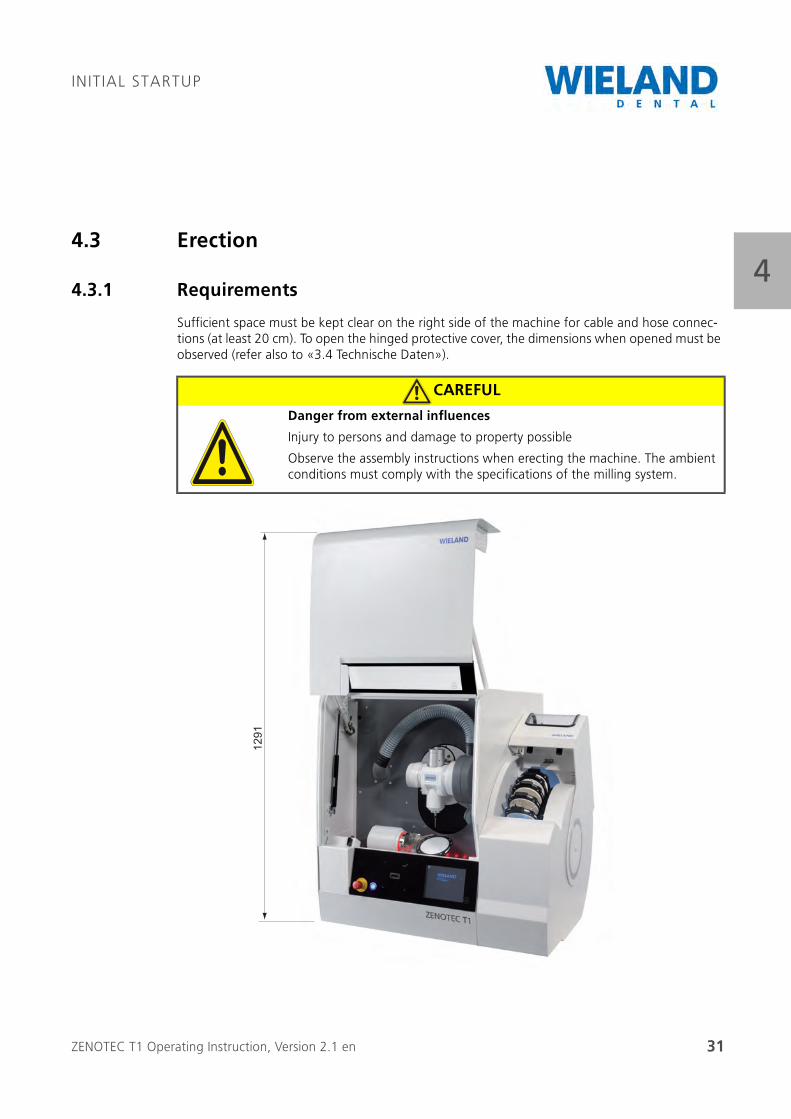
4.3.1 Requirements
Sufficient space must be kept clear on the right side of the machine for cable and hose connec-tions (at least 20 cm). To open the hinged protective cover, the dimensions when opened must be observed (refer also to «3.4 Technische Daten»).
CAREFUL
Danger from external influences
Injury to persons and damage to property possible
Observe the assembly instructions when erecting the machine. The ambient conditions must comply with the specifications of the milling system.
1291
ZENOTEC T1 Operating Instruction, Version 2.1 en 32
INITIAL STARTUP
4Generally, the location of assembly should not be in the vicinity of disturbing influences and should be as vibration-free as possible.
The machine must be placed horizontally on a solid, level surface with sufficient bearing capacity The machine is erected and aligned by trained expert personnel.
There must be enough space behind the machine for ventilation (> 150 mm).
Room for cable and the hose connections must be kept free on the left side (approx. 150 mm).
To be able to fully open the hinged protective cover, enough space should be kept free compliant to the figure above.
Enough space must be kept free in front of the machine for setup and operation. Ideally, the space on which the machine is deposited should have a free working and service area of 150x100 cm.
Bearing capacity: Take into account the weight of the machine (optional: including accessories) and its charge (refer to «3.4 Technische Daten»)..
ZENOTEC T1 Operating Instruction, Version 2.1 en 33
INITIAL STARTUP
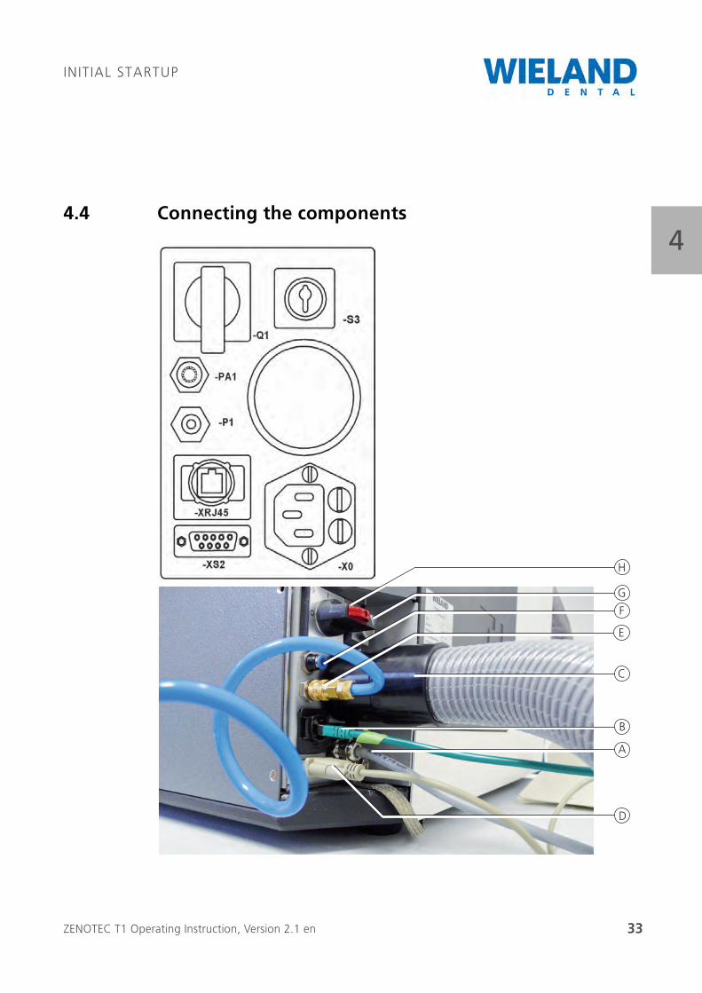
44.4 Connecting the components
A
B
C
E
D
F
G
H
ZENOTEC T1 Operating Instruction, Version 2.1 en 34
INITIAL STARTUP
4
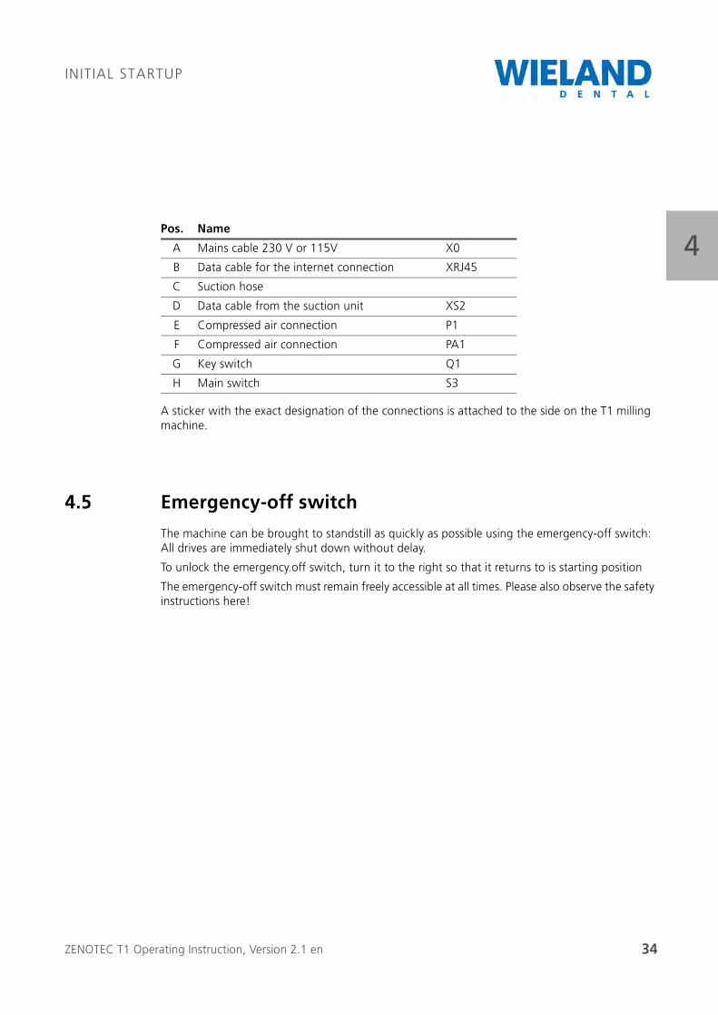
A sticker with the exact designation of the connections is attached to the side on the T1 milling machine.
4.5 Emergency-off switch
The machine can be brought to standstill as quickly as possible using the emergency-off switch: All drives are immediately shut down without delay.
To unlock the emergency.off switch, turn it to the right so that it returns to is starting position
The emergency-off switch must remain freely accessible at all times. Please also observe the safety instructions here!
Pos. Name
A Mains cable 230 V or 115V X0
B Data cable for the internet connection XRJ45
C Suction hose
D Data cable from the suction unit XS2
E Compressed air connection P1
F Compressed air connection PA1
G Key switch Q1
H Main switch S3
ZENOTEC T1 Operating Instruction, Version 2.1 en 35
OPERATION
55 Operation
5.1 Requirements
Exhaustive training from the staff of WIELAND Dental + Technik GmbH & Co. KG is a require-ment for the expert operation of the ZENOTEC T1 System.
5.2 Requirements of the operating personnel
Each and every person concerned with the startup and operation of the ZENOTEC T1 System must
be appropriately trained and instructed for the activity at hand
and must have read and understood the operating instructions, especially the “Safety instruc-tions” and "Operating the system" chapters.
Personnel to be trained may only work at the milling system under supervision from an experi-enced person.
The machine name T1 must never be changed when making the settings (e.g. in service mode). If the machine name is changes then remote mainte-nance via Netview is no longer possible because your support partner can no longer find the machine.
All safety instructions contained in the operating instructions must be read and understood. Maintenance work on the milling system may only be carried out by authorised expert personnel.
CAREFUL
Weargoggles/ear protection
When working at the machine for longer periods of time, we recommend you wear ear protection and goggles.
ZENOTEC T1 Operating Instruction, Version 2.1 en 36
OPERATION
55.3 Conventions
The following conventions are used to explain the software in these operating instructions:
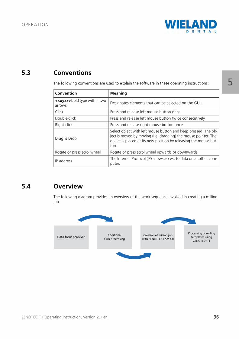
5.4 Overview
The following diagram provides an overview of the work sequence involved in creating a milling job.
Convention Meaning
<<xyz>>bold type within two arrows
Designates elements that can be selected on the GUI.
Click Press and release left mouse button once.
Double-click Press and release left mouse button twice consecutively.
Right-click Press and release right mouse button once.
Drag & Drop
Select object with left mouse button and keep pressed. The ob-ject is moved by moving (i.e. dragging) the mouse pointer. The object is placed at its new position by releasing the mouse but-ton.
Rotate or press scrollwheel Rotate or press scrollwheel upwards or downwards.
IP addressThe Internet Protocol (IP) allows access to data on another com-puter.
Data from scannerAdditional
CAD processing
Creation of milling job
with ZENOTEC® CAM 4.0
Processing of milling
templates using
ZENOTEC® T1
ZENOTEC T1 Operating Instruction, Version 2.1 en 37
OPERATION
55.5 Generating data with ZENOTEC CAM 4.0 Plus
5.5.1 General information
The software, including its corresponding documentation, is protected by copyright. It is generally forbidden to copy protected material This software must not be reproduced in part or as a whole nor copied to other media. Whoever copies or reproduces the software without the express written permission of WIELAND Dental + Technik GmbH & Co. KG die Software is liable to prose-cution.
The software description of the ZENOTEC CAM 4.0 Plus is in a separate document delivered with the ZENOTEC T1 System.
Instead of the ZENOTEC CAM 4.0 Plus, another CAM software can be installed by the customer. Interfaces to various manufacturers with compatible CAM software packages are provided by WIELAND on request.
The minimum requirements of the CAM PC are: DualCore Processor, 2 GB RAM, Open GL graphics board for 3D applications and WINDOWS XP.
5.5.2 Requirements
The requirement to operate the software is a successful initial installation of ZENOTEC CAM 4.0 Plus and its corresponding programs. Detailed information on initial installation is contained in separate operating instructions.
The software is comprised of several parts. The database to store the jobs is inside the T1 milling machine and is already preinstalled.
The GUI is on one or more separate computers which must be connected to the ZENOTEC T1 System by a network. You can access the data base from these computers.
A maximum of 5 computers can access the database of the milling machine.
Additional installations are possible on request
To work with the ZENOTEC CAM 4.0 Plus software you require a license dongle. This is already preinstalled in the milling machine.
Each additional license requires its own dongle.
ZENOTEC T1 Operating Instruction, Version 2.1 en 38
OPERATION
55.6 Operation via web interface
The web interface is used for managing milling jobs, blanks and tools. Operation of the ZENOTEC T1 via the web interface is described in the following. Using a common browser:
Milling jobs can be started and managed.
Blanks can be managed and checked.
Tools can be registered and managed.
You can access the web interface using Microsoft Internet Explorer 5.0 and higher, or any other standard browser.
Requirements
Exhaustive training from the staff of WIELAND Dental + Technik GmbH & Co. KG is a requirement for the expert operation of the milling system.
The T1 milling machine can be installed with or without a stack. The contents on the screen vary depending on the version delivered.
When useful, both versions are always taken into account or shown in the operating instructions
ZENOTEC T1 Operating Instruction, Version 2.1 en 39
OPERATION
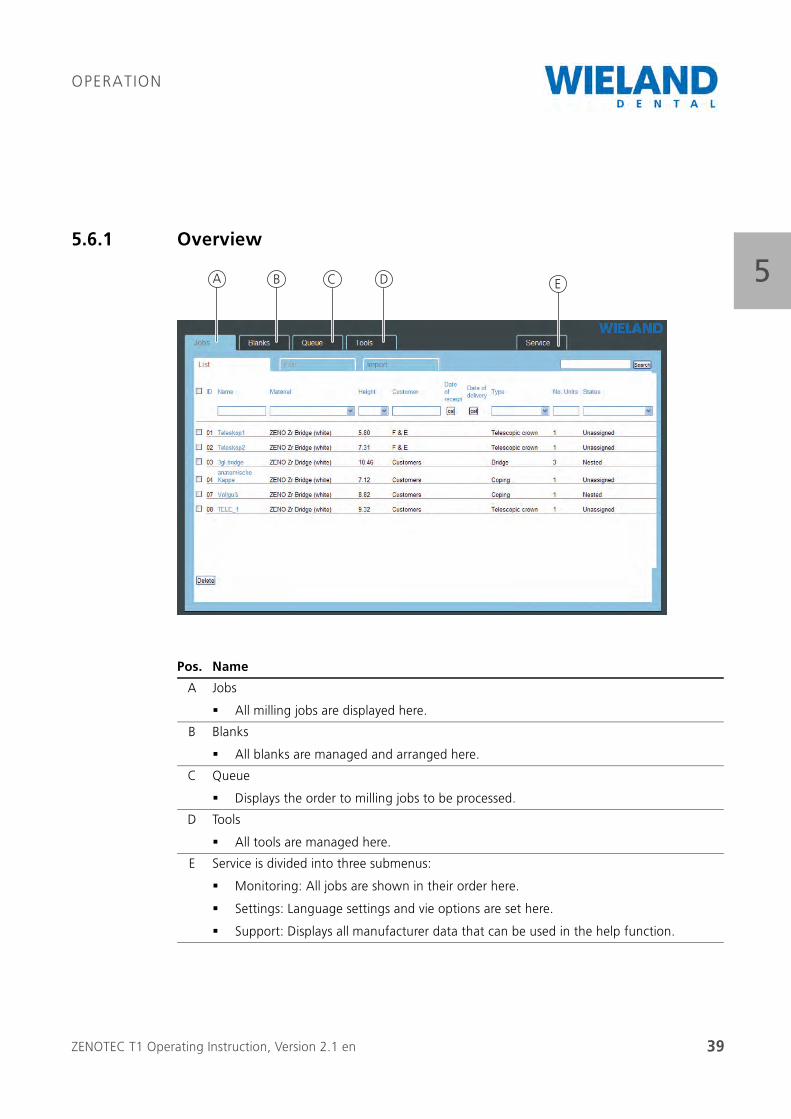
55.6.1 Overview
Pos. Name
A Jobs
All milling jobs are displayed here.
B Blanks
All blanks are managed and arranged here.
C Queue
Displays the order to milling jobs to be processed.
D Tools
All tools are managed here.
E Service is divided into three submenus:
Monitoring: All jobs are shown in their order here.
Settings: Language settings and vie options are set here.
Support: Displays all manufacturer data that can be used in the help function.
A B C D E
ZENOTEC T1 Operating Instruction, Version 2.1 en 40
OPERATION
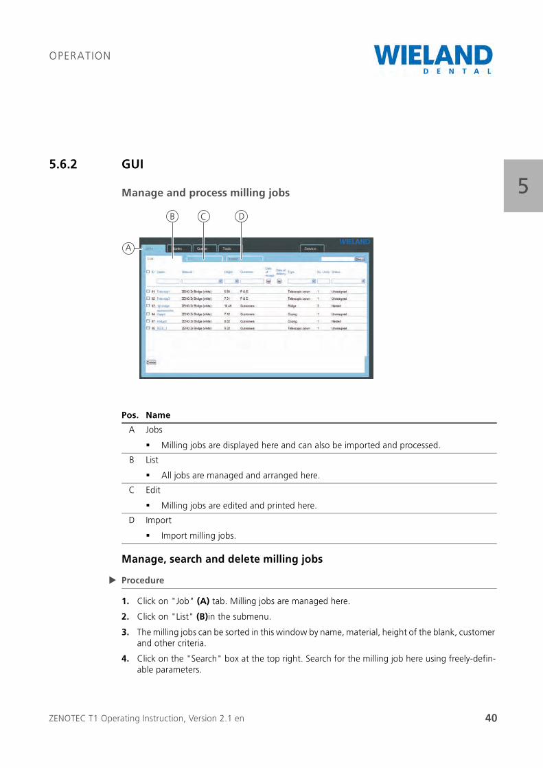
55.6.2 GUI
Manage and process milling jobs
Manage, search and delete milling jobs
Procedure
1. Click on "Job" (A) tab. Milling jobs are managed here.
2. Click on "List" (B)in the submenu.
3. The milling jobs can be sorted in this window by name, material, height of the blank, customer and other criteria.
4. Click on the "Search" box at the top right. Search for the milling job here using freely-defin-able parameters.
Pos. Name
A Jobs
Milling jobs are displayed here and can also be imported and processed.
B List
All jobs are managed and arranged here.
C Edit
Milling jobs are edited and printed here.
D Import
Import milling jobs.
A
B C D
ZENOTEC T1 Operating Instruction, Version 2.1 en 41
OPERATION
55. Click on "Date of Receipt"or "Date of Delivery" check box. The date of delivery or date of
receipt is displayed
6. Select the milling job by setting a mark in the respective check box. Delete the job with the "Delete" button.
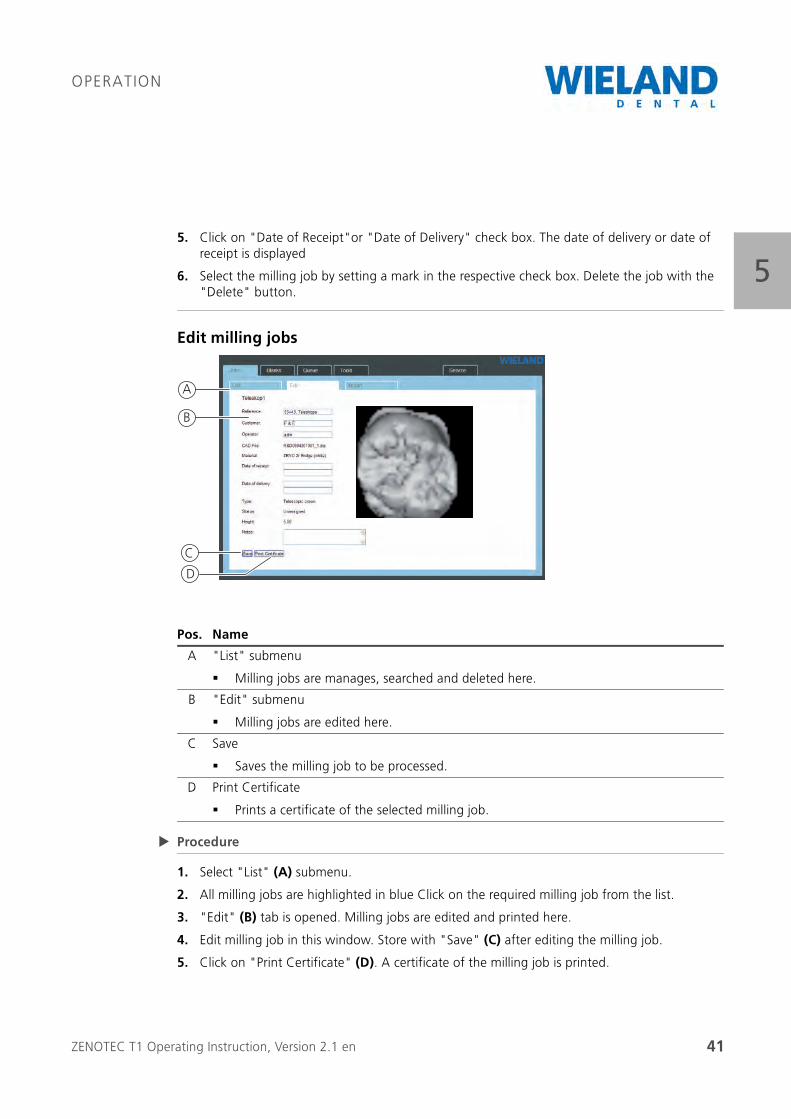
Edit milling jobs
Procedure
1. Select "List" (A) submenu.
2. All milling jobs are highlighted in blue Click on the required milling job from the list.
3. "Edit" (B) tab is opened. Milling jobs are edited and printed here.
4. Edit milling job in this window. Store with "Save" (C) after editing the milling job.
5. Click on "Print Certificate" (D). A certificate of the milling job is printed.
Pos. Name
A "List" submenu
Milling jobs are manages, searched and deleted here.
B "Edit" submenu
Milling jobs are edited here.
C Save
Saves the milling job to be processed.
D Print Certificate
Prints a certificate of the selected milling job.
B
A
C
D
ZENOTEC T1 Operating Instruction, Version 2.1 en 42
OPERATION
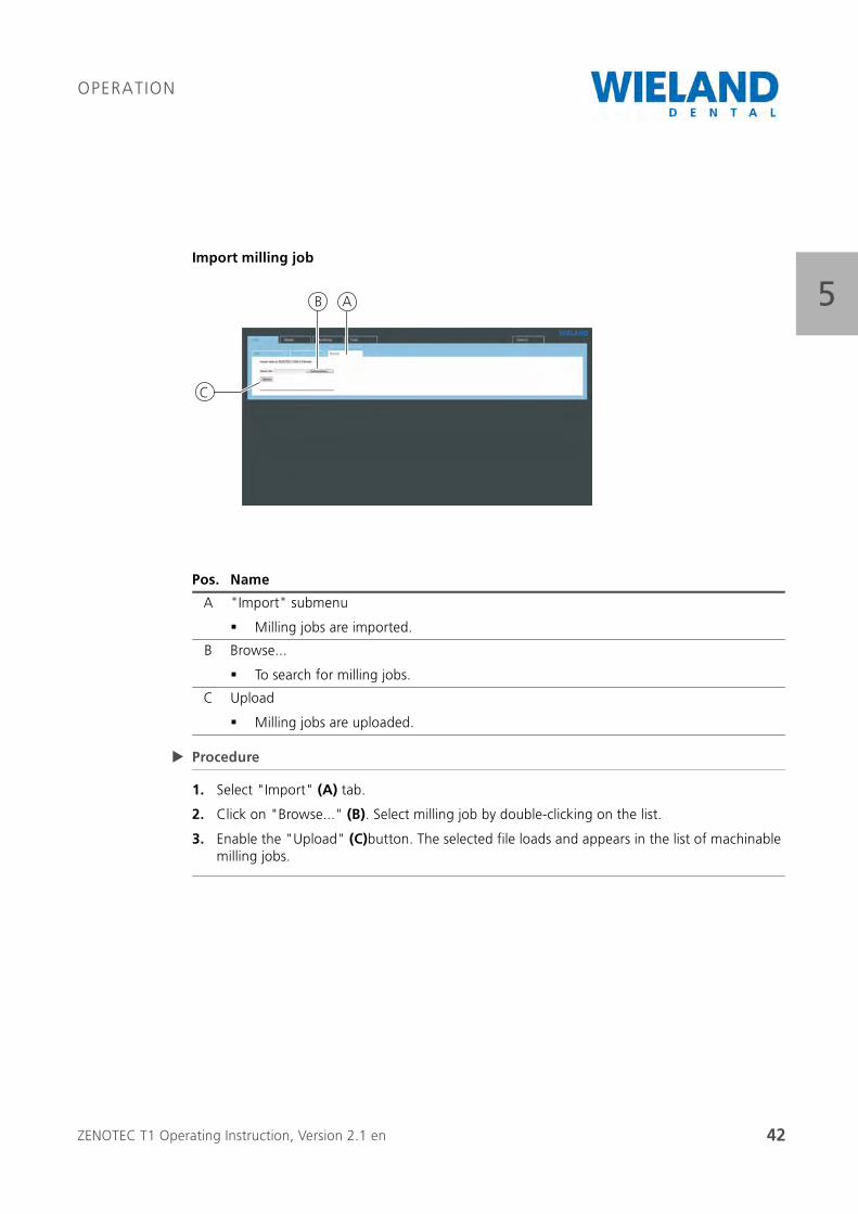
5Import milling job
Procedure
1. Select "Import" (A) tab.
2. Click on "Browse..." (B). Select milling job by double-clicking on the list.
3. Enable the "Upload" (C)button. The selected file loads and appears in the list of machinable milling jobs.
Pos. Name
A "Import" submenu
Milling jobs are imported.
B Browse...
To search for milling jobs.
C Upload
Milling jobs are uploaded.
A
C
B
ZENOTEC T1 Operating Instruction, Version 2.1 en 43
OPERATION
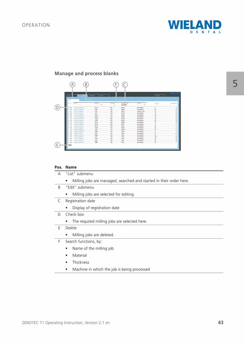
5Manage and process blanks
Pos. Name
A "List" submenu
Milling jobs are managed, searched and started in their order here.
B "Edit" submenu
Milling jobs are selected for editing.
C Registration date
Display of registration date
D Check box
The required milling jobs are selected here.
E Delete
Milling jobs are deleted.
F Search functions, by:
Name of the milling job
Material
Thickness
Machine in which the job is being processed
A B C
D
E
F
ZENOTEC T1 Operating Instruction, Version 2.1 en 44
OPERATION
5Manage, search and delete blanks
Procedure
1. Click on "Blank" (A) tab.
2. Click on "List" (B)in the submenu.
3. The blanks can be sorted in this window by name, material, thickness, place of manufacture and other criteria (F).
4. The sorting function is run immediately after selecting it.
5. Click on the "Registration Date" (C) check box. The registration date is displayed.
6. Select the blank by setting a mark in the respective check box. Delete the blank with the "Delete" button.
ZENOTEC T1 Operating Instruction, Version 2.1 en 45
OPERATION
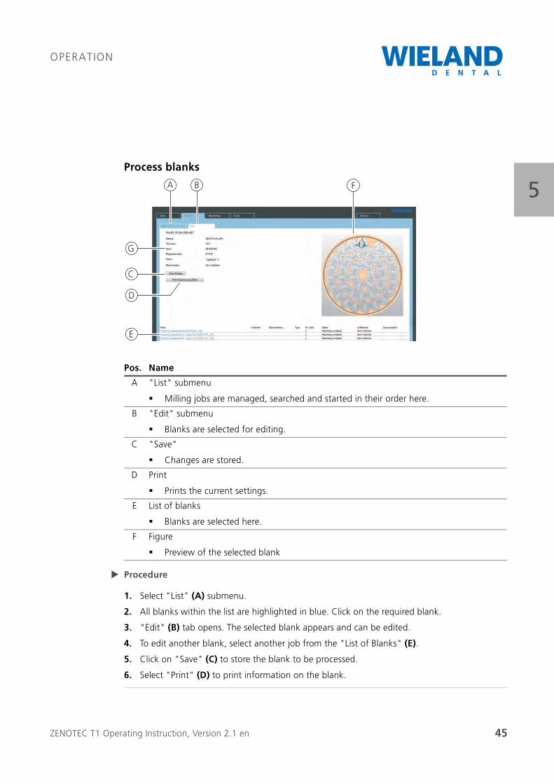
5Process blanks
Procedure
1. Select "List" (A) submenu.
2. All blanks within the list are highlighted in blue. Click on the required blank.
3. "Edit" (B) tab opens. The selected blank appears and can be edited.
4. To edit another blank, select another job from the "List of Blanks" (E).
5. Click on "Save" (C) to store the blank to be processed.
6. Select "Print" (D) to print information on the blank.
Pos. Name
A "List" submenu
Milling jobs are managed, searched and started in their order here.
B "Edit" submenu
Blanks are selected for editing.
C "Save"
Changes are stored.
D Print
Prints the current settings.
E List of blanks
Blanks are selected here.
F Figure
Preview of the selected blank
A B
D
E
F
C
G
ZENOTEC T1 Operating Instruction, Version 2.1 en 46
OPERATION
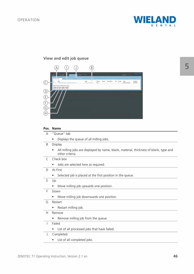
5View and edit job queue
Pos. Name
A "Queue" tab
Displays the queue of all milling jobs.
B Display
All milling jobs are displayed by name, blank, material, thickness of blank, type and other criteria.
C Check box
Jobs are selected here as required.
D At First
Selected job is placed at the first position in the queue.
E Up
Move milling job upwards one position.
F Down
Move milling job downwards one position.
G Restart
Restart milling job.
H Remove
Remove milling job from the queue.
I Failed
List of all processed jobs that have failed.
J Completed
List of all completed jobs.
C
A B
D
E
F
H
G
I J
ZENOTEC T1 Operating Instruction, Version 2.1 en 47
OPERATION
5Manage queue
Procedure
1. Click on "Queue" (A) tab. All jobs are managed here.
2. The jobs can be moved up and down by one position in this window.
3. Click on the job check box. Move the job up or down by one position by clicking on "Up" (E)or "Down"(F).
4. Select milling job check box. Set job to the first position by clicking on "At First" (C).
Delete milling job from queue
Procedure
1. Click on "Queue" (A) tab.
2. Search for job in queue. Click on the milling job check box.
3. Select "Remove" (H)button. The job is deleted.
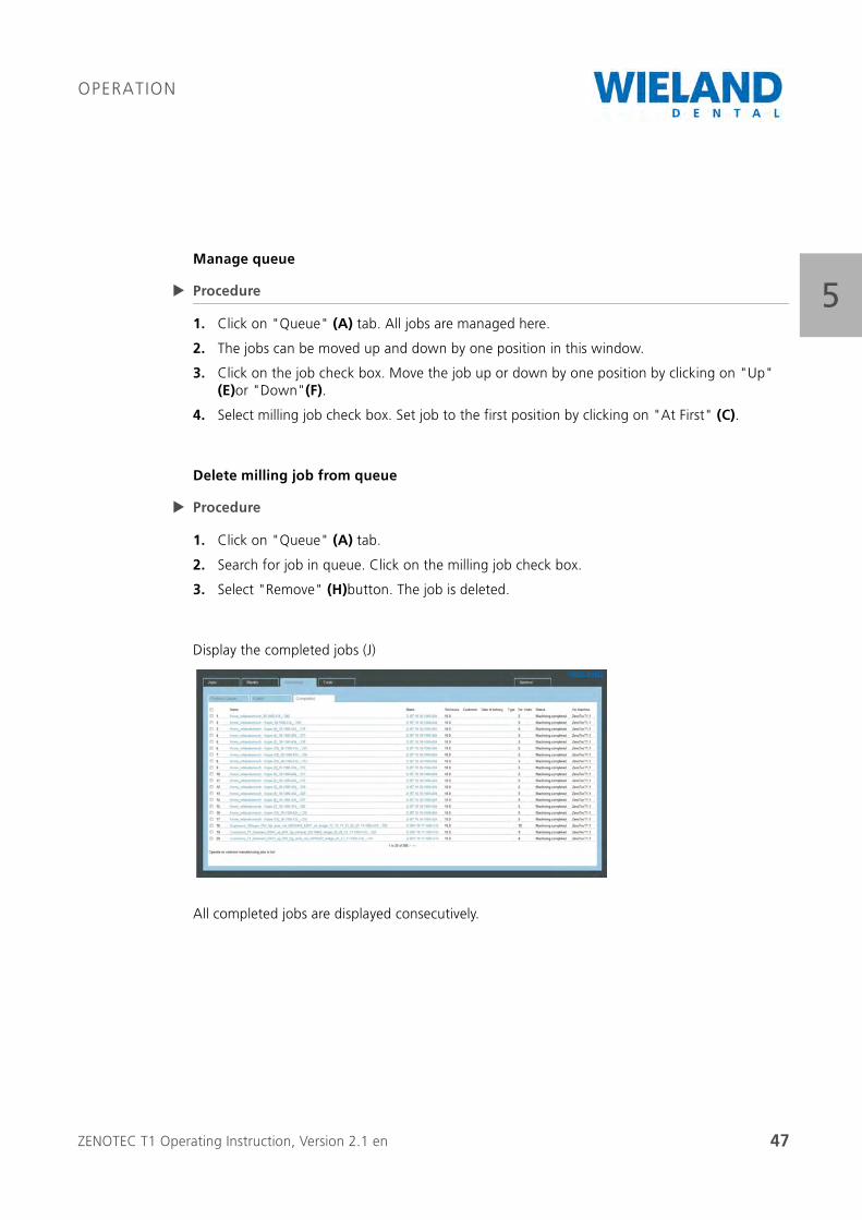
Display the completed jobs (J)
All completed jobs are displayed consecutively.
ZENOTEC T1 Operating Instruction, Version 2.1 en 48
OPERATION
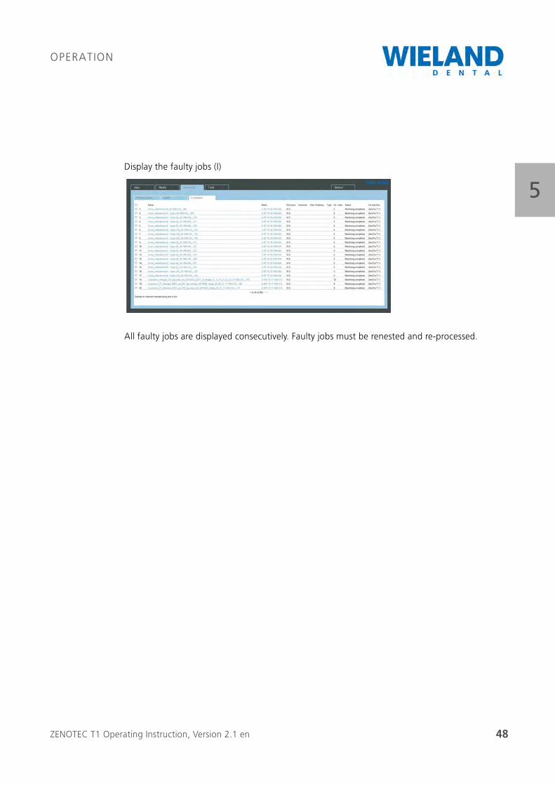
5Display the faulty jobs (I)
All faulty jobs are displayed consecutively. Faulty jobs must be renested and re-processed.
ZENOTEC T1 Operating Instruction, Version 2.1 en 49
OPERATION
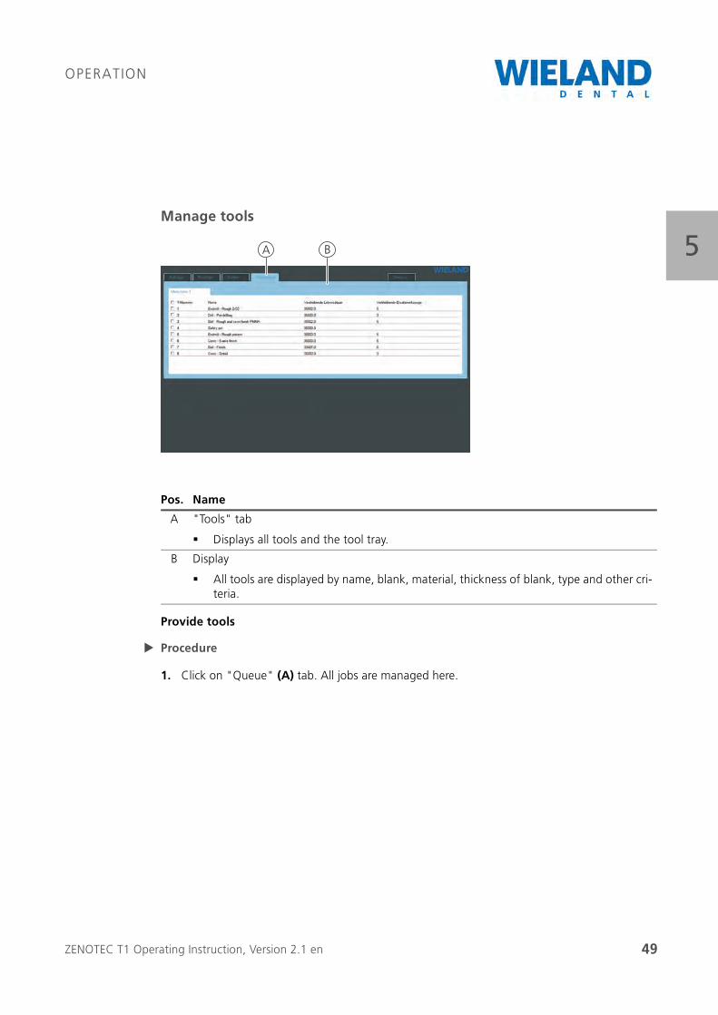
5Manage tools
Provide tools
Procedure
1. Click on "Queue" (A) tab. All jobs are managed here.
Pos. Name
A "Tools" tab
Displays all tools and the tool tray.
B Display
All tools are displayed by name, blank, material, thickness of blank, type and other cri-teria.
A B
ZENOTEC T1 Operating Instruction, Version 2.1 en 50
OPERATION
5Service
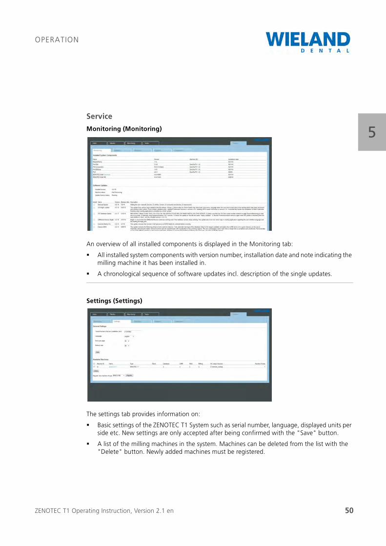
Monitoring (Monitoring)
An overview of all installed components is displayed in the Monitoring tab:
All installed system components with version number, installation date and note indicating the milling machine it has been installed in.
A chronological sequence of software updates incl. description of the single updates.
Settings (Settings)
The settings tab provides information on:
Basic settings of the ZENOTEC T1 System such as serial number, language, displayed units per side etc. New settings are only accepted after being confirmed with the "Save" button.
A list of the milling machines in the system. Machines can be deleted from the list with the "Delete" button. Newly added machines must be registered.
ZENOTEC T1 Operating Instruction, Version 2.1 en 51
OPERATION
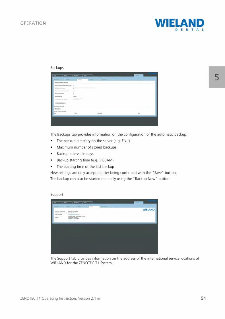
5Backups
The Backups tab provides information on the configuration of the automatic backup:
The backup directory on the server (e.g. E:\...)
Maximum number of stored backups
Backup interval in days
Backup starting time (e.g. 3:00AM)
The starting time of the last backup
New settings are only accepted after being confirmed with the "Save" button.
The backup can also be started manually using the "Backup Now" button.
Support
The Support tab provides information on the address of the international service locations of WIELAND for the ZENOTEC T1 System.
ZENOTEC T1 Operating Instruction, Version 2.1 en 52
OPERATION
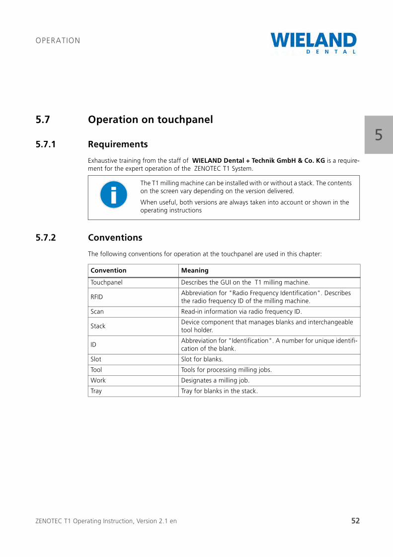
55.7 Operation on touchpanel
5.7.1 Requirements
Exhaustive training from the staff of WIELAND Dental + Technik GmbH & Co. KG is a require-ment for the expert operation of the ZENOTEC T1 System.
5.7.2 Conventions
The following conventions for operation at the touchpanel are used in this chapter:
The T1 milling machine can be installed with or without a stack. The contents on the screen vary depending on the version delivered.
When useful, both versions are always taken into account or shown in the operating instructions
Convention Meaning
Touchpanel Describes the GUI on the T1 milling machine.
RFIDAbbreviation for "Radio Frequency Identification". Describes the radio frequency ID of the milling machine.
Scan Read-in information via radio frequency ID.
StackDevice component that manages blanks and interchangeable tool holder.
IDAbbreviation for "Identification". A number for unique identifi-cation of the blank.
Slot Slot for blanks.
Tool Tools for processing milling jobs.
Work Designates a milling job.
Tray Tray for blanks in the stack.
ZENOTEC T1 Operating Instruction, Version 2.1 en 53
OPERATION
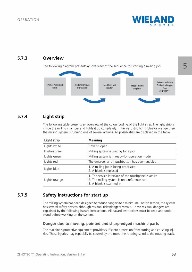
55.7.3 Overview
The following diagram presents an overview of the sequence for starting a milling job.
5.7.4 Light strip
The following table presents an overview of the colour coding of the light strip. The light strip is inside the milling chamber and lights it up completely. If the light strip lights blue or orange then the milling system is running one of several actions. All possibilities are displayed in the table.
5.7.5 Safety instructions for start up
The milling system has been designed to reduce dangers to a minimum. For this reason, the system has several safety devices although residual risks/dangers remain. These residual dangers are explained by the following hazard instructions. All hazard instructions must be read and under-stood before working on the system.
Danger due to moving, pointed and sharp-edged machine parts
The machine's protective equipment provides sufficient protection from cutting and crushing inju-ries. These injuries may especially be caused by the tools, the rotating spindle, the rotating stack,
Read-in blanks via
RFID scanner
Finished milling job
existsInsert tools and
register
Take out and clean
finished milling job
from
ZENOTEC® T1
Process milling
templates
Light strip Meaning
Lights white Cover is open
Flashes green Milling system is waiting for a job
Lights green Milling system is in ready-for-operation mode
Lights red The emergency-off pushbutton has been enabled
Lights blue1. A milling job is being processed2. A blank is replaced
Lights orange1. The service interface of the touchpanel is active2. The milling system is on a reference run3. A blank is scanned in
ZENOTEC T1 Operating Instruction, Version 2.1 en 54
OPERATION
5the pneumatically moved parts and by milling motion. For this reason, the system may only be operated when the protective equipment has been installed and is fully intact.
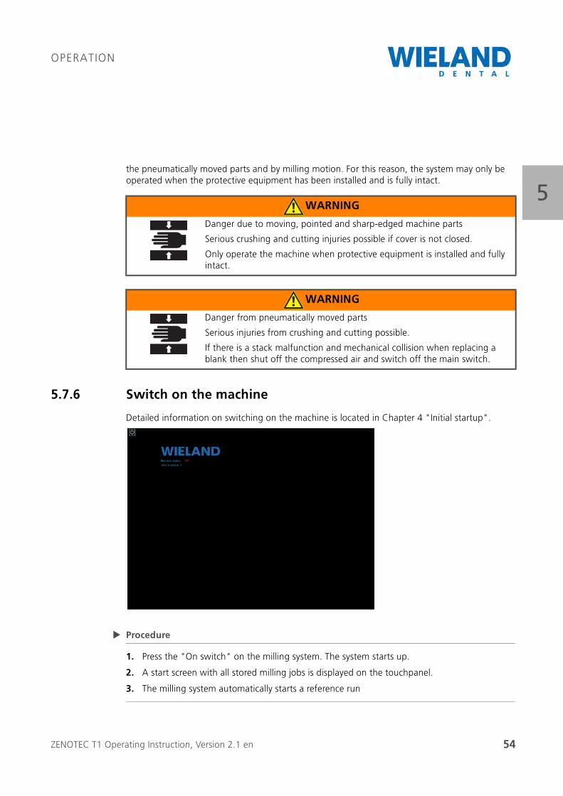
5.7.6 Switch on the machine
Detailed information on switching on the machine is located in Chapter 4 "Initial startup".
Procedure
1. Press the "On switch" on the milling system. The system starts up.
2. A start screen with all stored milling jobs is displayed on the touchpanel.
3. The milling system automatically starts a reference run
WARNING
Danger due to moving, pointed and sharp-edged machine parts
Serious crushing and cutting injuries possible if cover is not closed.
Only operate the machine when protective equipment is installed and fully intact.
WARNING
Danger from pneumatically moved parts
Serious injuries from crushing and cutting possible.
If there is a stack malfunction and mechanical collision when replacing a blank then shut off the compressed air and switch off the main switch.
ZENOTEC T1 Operating Instruction, Version 2.1 en 55
OPERATION
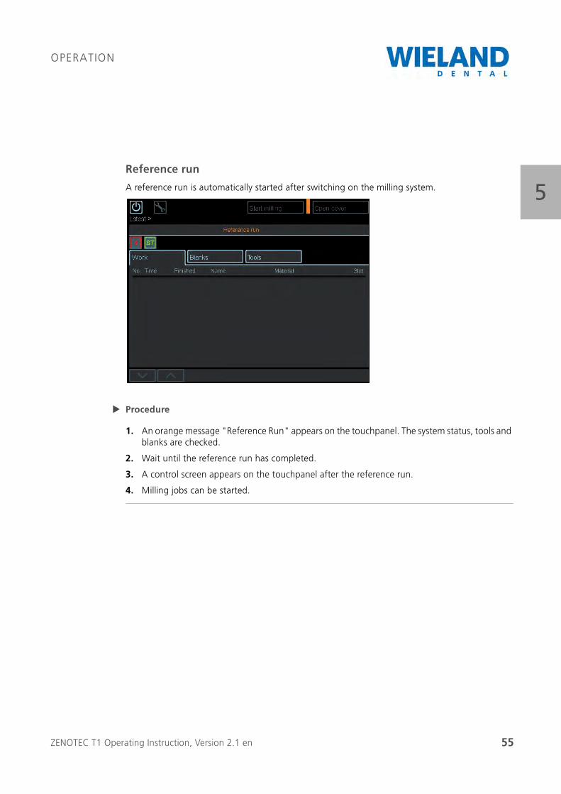
5Reference run
A reference run is automatically started after switching on the milling system.
Procedure
1. An orange message "Reference Run" appears on the touchpanel. The system status, tools and blanks are checked.
2. Wait until the reference run has completed.
3. A control screen appears on the touchpanel after the reference run.
4. Milling jobs can be started.

ZENOTEC T1 Operating Instruction, Version 2.1 en 56
OPERATION
5Open and close cover
Procedure
1. The "Open cover" option is in every menu time independent of the tabs.
2. Click on "Open cover" (A) on the touchpanel. The cover is opened.
3. The message "Cover open" appears.
Pos. Name
A Open cover
The cover is opened.
A

ZENOTEC T1 Operating Instruction, Version 2.1 en 57
OPERATION
5Open cover, continued
Procedure
1. A message appears:
"The cover must be closed to start the machine. If necessary, deactivate the emergency-offand close the cover to be able to switch on the machine.
2. Press "Ok" (B) on the touchpanel.
3. Confirm the new message Machine ON" with "OK" (B). The cover is closed automatically.
Pos. Name
A Open gripper
The gripper can be manually opened.
B OK
Confirms opening of the cover.
C Suction unit on
Pressing this switches on the suction unit manually.
A
B
C
ZENOTEC T1 Operating Instruction, Version 2.1 en 58
OPERATION
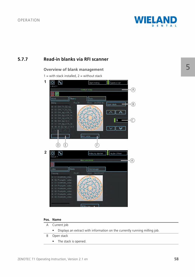
55.7.7 Read-in blanks via RFI scanner
Overview of blank management
1 = with stack installed, 2 = without stack
Pos. Name
A Current job
Displays an extract with information on the currently running milling job.
B Open stack
The stack is opened.
ED F
B
C
A
A
1
2
ZENOTEC T1 Operating Instruction, Version 2.1 en 59
OPERATION
5
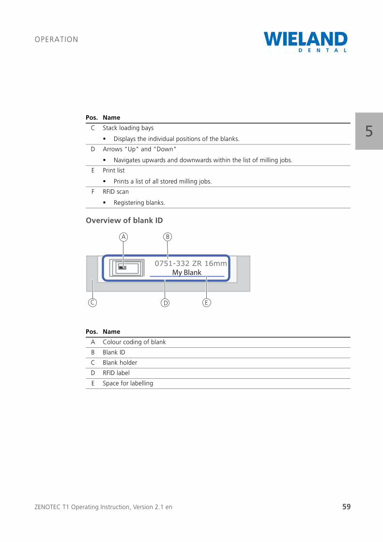
Overview of blank ID
C Stack loading bays
Displays the individual positions of the blanks.
D Arrows "Up" and "Down"
Navigates upwards and downwards within the list of milling jobs.
E Print list
Prints a list of all stored milling jobs.
F RFID scan
Registering blanks.
Pos. Name
A Colour coding of blank
B Blank ID
C Blank holder
D RFID label
E Space for labelling
Pos. Name
0751-332 ZR 16mmMein Blank
A
DC
B
E
My Blank
ZENOTEC T1 Operating Instruction, Version 2.1 en 60
OPERATION
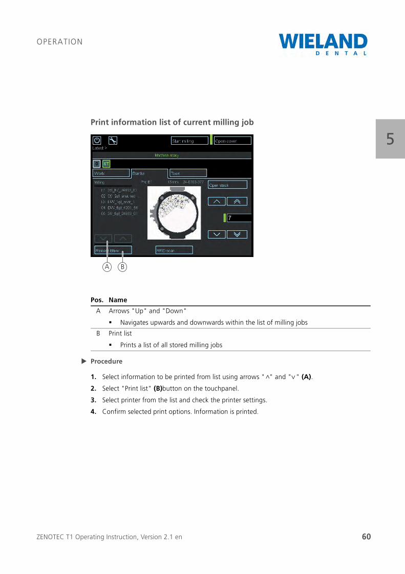
5Print information list of current milling job
Procedure
1. Select information to be printed from list using arrows " " and " " (A).
2. Select "Print list" (B)button on the touchpanel.
3. Select printer from the list and check the printer settings.
4. Confirm selected print options. Information is printed.
Pos. Name
A Arrows "Up" and "Down"
Navigates upwards and downwards within the list of milling jobs
B Print list
Prints a list of all stored milling jobs
BA
<
<
ZENOTEC T1 Operating Instruction, Version 2.1 en 61
OPERATION
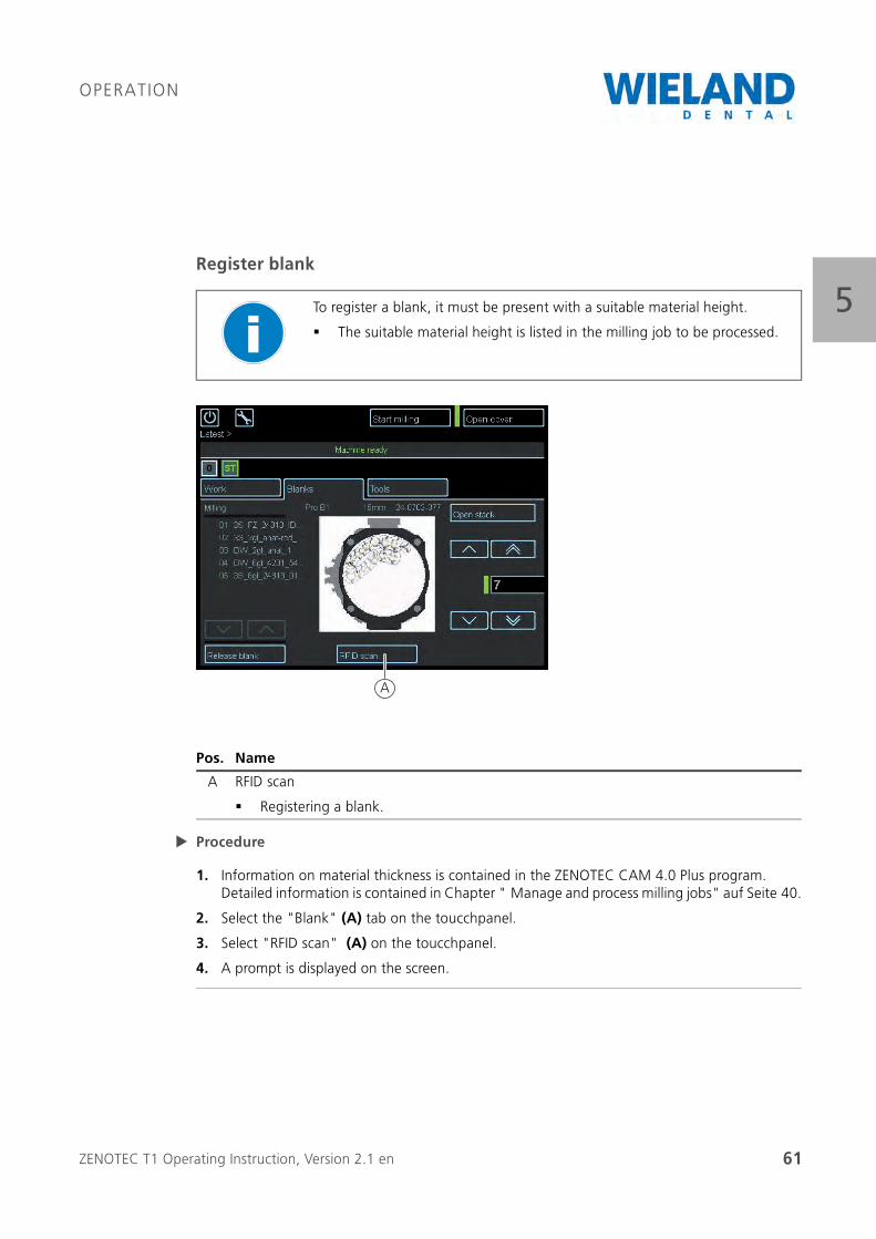
5Register blank
Procedure
1. Information on material thickness is contained in the ZENOTEC CAM 4.0 Plus program. Detailed information is contained in Chapter " Manage and process milling jobs" auf Seite 40.
2. Select the "Blank" (A) tab on the toucchpanel.
3. Select "RFID scan" (A) on the toucchpanel.
4. A prompt is displayed on the screen.
To register a blank, it must be present with a suitable material height.
The suitable material height is listed in the milling job to be processed.
Pos. Name
A RFID scan
Registering a blank.
A
ZENOTEC T1 Operating Instruction, Version 2.1 en 62
OPERATION
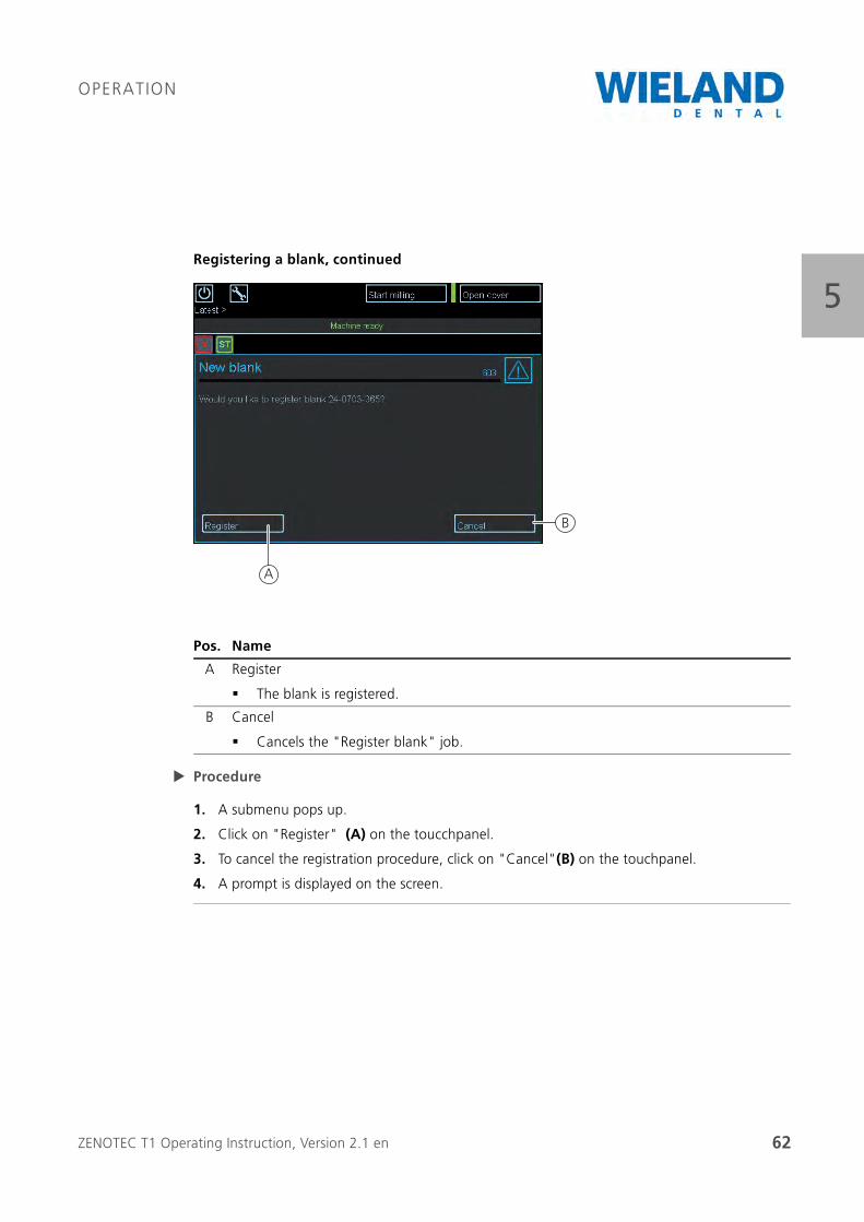
5Registering a blank, continued
Procedure
1. A submenu pops up.
2. Click on "Register" (A) on the toucchpanel.
3. To cancel the registration procedure, click on "Cancel"(B) on the touchpanel.
4. A prompt is displayed on the screen.
Pos. Name
A Register
The blank is registered.
B Cancel
Cancels the "Register blank" job.
A
B
ZENOTEC T1 Operating Instruction, Version 2.1 en 63
OPERATION
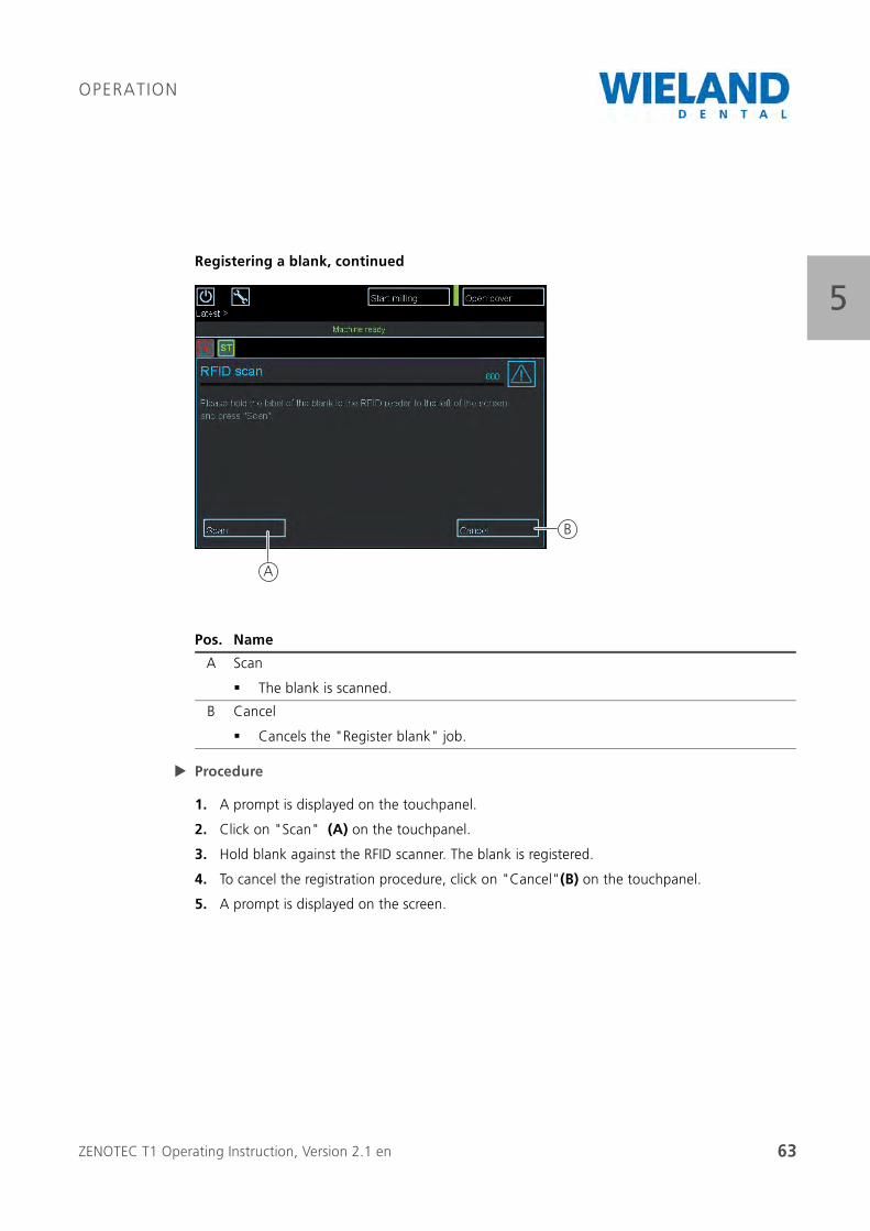
5Registering a blank, continued
Procedure
1. A prompt is displayed on the touchpanel.
2. Click on "Scan" (A) on the touchpanel.
3. Hold blank against the RFID scanner. The blank is registered.
4. To cancel the registration procedure, click on "Cancel"(B) on the touchpanel.
5. A prompt is displayed on the screen.
Pos. Name
A Scan
The blank is scanned.
B Cancel
Cancels the "Register blank" job.
A
B

ZENOTEC T1 Operating Instruction, Version 2.1 en 64
OPERATION
5Registering a blank, continued
Procedure
1. Do not remove the blank from the RFID scanner during the registration procedure.
2. Information appears: "Scanning blank. Please keep blank held against the RFID scanner".
3. A prompt is displayed on the screen.
ZENOTEC T1 Operating Instruction, Version 2.1 en 65
OPERATION
5
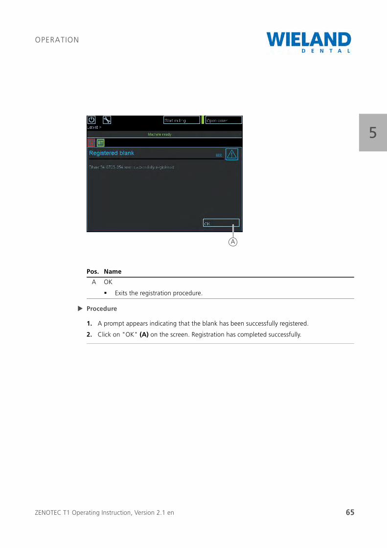
Procedure
1. A prompt appears indicating that the blank has been successfully registered.
2. Click on "OK" (A) on the screen. Registration has completed successfully.
Pos. Name
A OK
Exits the registration procedure.
A
ZENOTEC T1 Operating Instruction, Version 2.1 en 66
OPERATION
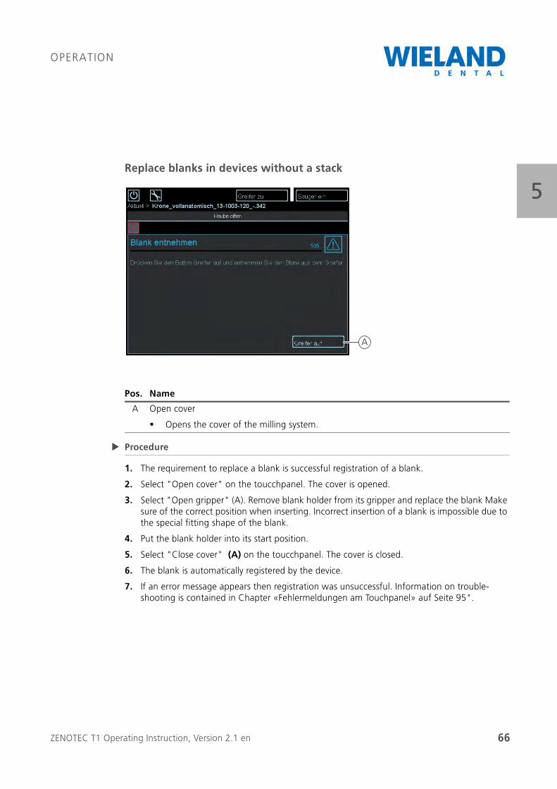
5Replace blanks in devices without a stack
Procedure
1. The requirement to replace a blank is successful registration of a blank.
2. Select "Open cover" on the toucchpanel. The cover is opened.
3. Select "Open gripper" (A). Remove blank holder from its gripper and replace the blank Make sure of the correct position when inserting. Incorrect insertion of a blank is impossible due to the special fitting shape of the blank.
4. Put the blank holder into its start position.
5. Select "Close cover" (A) on the toucchpanel. The cover is closed.
6. The blank is automatically registered by the device.
7. If an error message appears then registration was unsuccessful. Information on trouble-shooting is contained in Chapter «Fehlermeldungen am Touchpanel» auf Seite 95".
Pos. Name
A Open cover
Opens the cover of the milling system.
A
ZENOTEC T1 Operating Instruction, Version 2.1 en 67
OPERATION
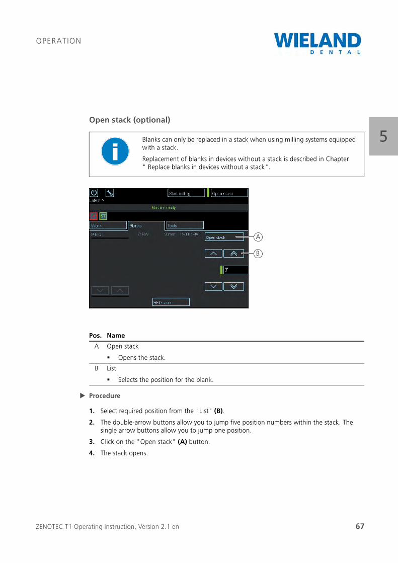
5Open stack (optional)
Procedure
1. Select required position from the "List" (B).
2. The double-arrow buttons allow you to jump five position numbers within the stack. The single arrow buttons allow you to jump one position.
3. Click on the "Open stack" (A) button.
4. The stack opens.
Blanks can only be replaced in a stack when using milling systems equipped with a stack.
Replacement of blanks in devices without a stack is described in Chapter " Replace blanks in devices without a stack".
Pos. Name
A Open stack
Opens the stack.
B List
Selects the position for the blank.
B
A
ZENOTEC T1 Operating Instruction, Version 2.1 en 68
OPERATION
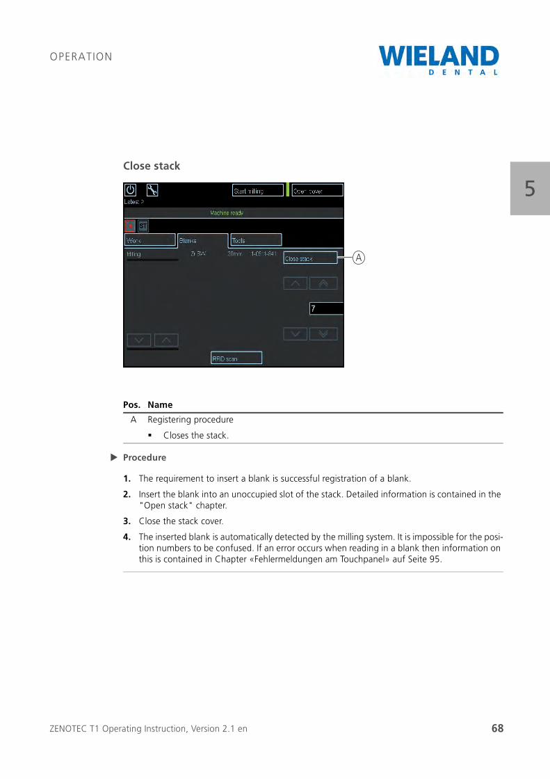
5Close stack
Procedure
1. The requirement to insert a blank is successful registration of a blank.
2. Insert the blank into an unoccupied slot of the stack. Detailed information is contained in the "Open stack" chapter.
3. Close the stack cover.
4. The inserted blank is automatically detected by the milling system. It is impossible for the posi-tion numbers to be confused. If an error occurs when reading in a blank then information on this is contained in Chapter «Fehlermeldungen am Touchpanel» auf Seite 95.
Pos. Name
A Registering procedure
Closes the stack.
A
ZENOTEC T1 Operating Instruction, Version 2.1 en 69
OPERATION
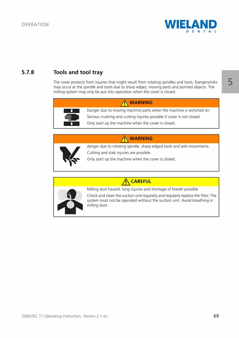
55.7.8 Tools and tool tray
The cover protects from injuries that might result from rotating spindles and tools. Dangers/risks may occur at the spindle and tools due to sharp edges, moving parts and pointed objects. The milling system may only be put into operation when the cover is closed.
WARNING
Danger due to moving machine parts when the machine is switched on
Serious crushing and cutting injuries possible if cover is not closed.
Only start up the machine when the cover is closed.
WARNING
danger due to rotating spindle, sharp-edged tools and axle movements
Cutting and stab injuries are possible.
Only start up the machine when the cover is closed.
CAREFUL
Milling dust hazard: lung injuries and shortage of breath possible
Check and clean the suction unit regularly and regularly replace the filter. The system must not be operated without the suction unit. Avoid breathing in milling dust.
ZENOTEC T1 Operating Instruction, Version 2.1 en 70
OPERATION
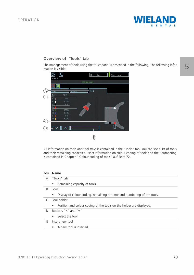
5Overview of "Tools" tab
The management of tools using the touchpanel is described in the following. The following infor-mation is visible:
All information on tools and tool trays is contained in the "Tools" tab. You can see a list of tools and their remaining capacities. Exact information on colour coding of tools and their numbering is contained in Chapter " Colour coding of tools" auf Seite 72.
Pos. Name
A "Tools" tab
Remaining capacity of tools.
B Tool
Display of colour coding, remaining runtime and numbering of the tools.
C Tool holder
Position and colour coding of the tools on the holder are displayed.
D Buttons " " and " "
Select the tool
E Insert new tool
A new tool is inserted.
C
D
E
B
A
<
<
ZENOTEC T1 Operating Instruction, Version 2.1 en 71
OPERATION
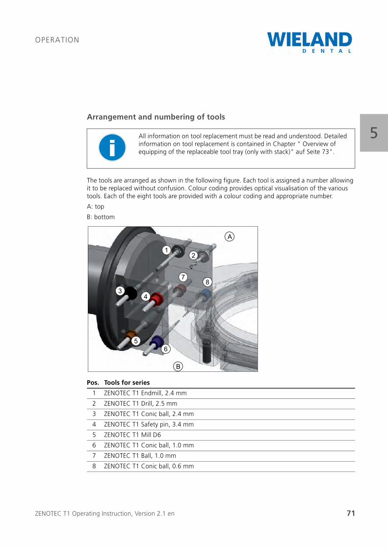
5Arrangement and numbering of tools
The tools are arranged as shown in the following figure. Each tool is assigned a number allowing it to be replaced without confusion. Colour coding provides optical visualisation of the various tools. Each of the eight tools are provided with a colour coding and appropriate number.
A: top
B: bottom
All information on tool replacement must be read and understood. Detailed information on tool replacement is contained in Chapter " Overview of equipping of the replaceable tool tray (only with stack)" auf Seite 73".
Pos. Tools for series
1 ZENOTEC T1 Endmill, 2.4 mm
2 ZENOTEC T1 Drill, 2.5 mm
3 ZENOTEC T1 Conic ball, 2.4 mm
4 ZENOTEC T1 Safety pin, 3.4 mm
5 ZENOTEC T1 Mill D6
6 ZENOTEC T1 Conic ball, 1.0 mm
7 ZENOTEC T1 Ball, 1.0 mm
8 ZENOTEC T1 Conic ball, 0.6 mm
12
34
56
78
A
B
ZENOTEC T1 Operating Instruction, Version 2.1 en 72
OPERATION
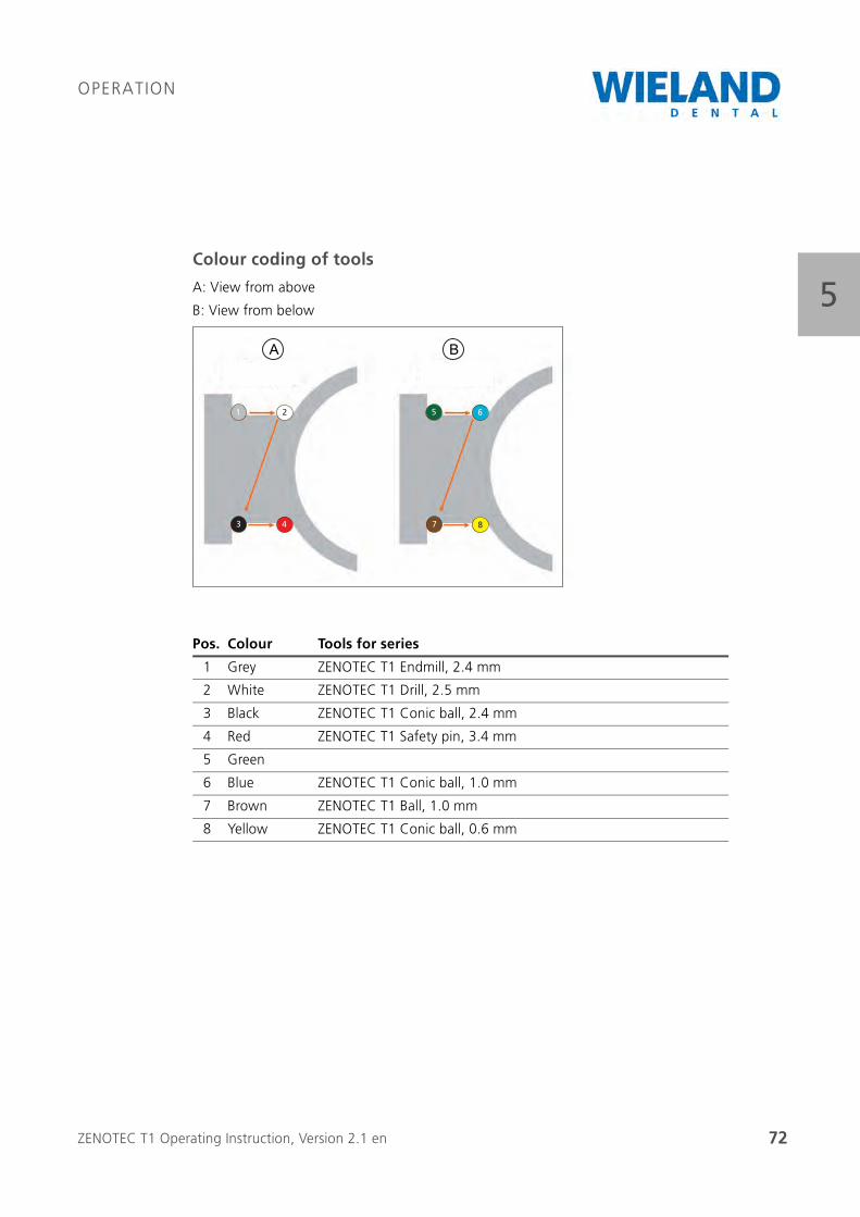
5Colour coding of tools
A: View from above
B: View from below
Pos. Colour Tools for series
1 Grey ZENOTEC T1 Endmill, 2.4 mm
2 White ZENOTEC T1 Drill, 2.5 mm
3 Black ZENOTEC T1 Conic ball, 2.4 mm
4 Red ZENOTEC T1 Safety pin, 3.4 mm
5 Green
6 Blue ZENOTEC T1 Conic ball, 1.0 mm
7 Brown ZENOTEC T1 Ball, 1.0 mm
8 Yellow ZENOTEC T1 Conic ball, 0.6 mm
1 2
3 4
5 6
7 8
A B
ZENOTEC T1 Operating Instruction, Version 2.1 en 73
OPERATION
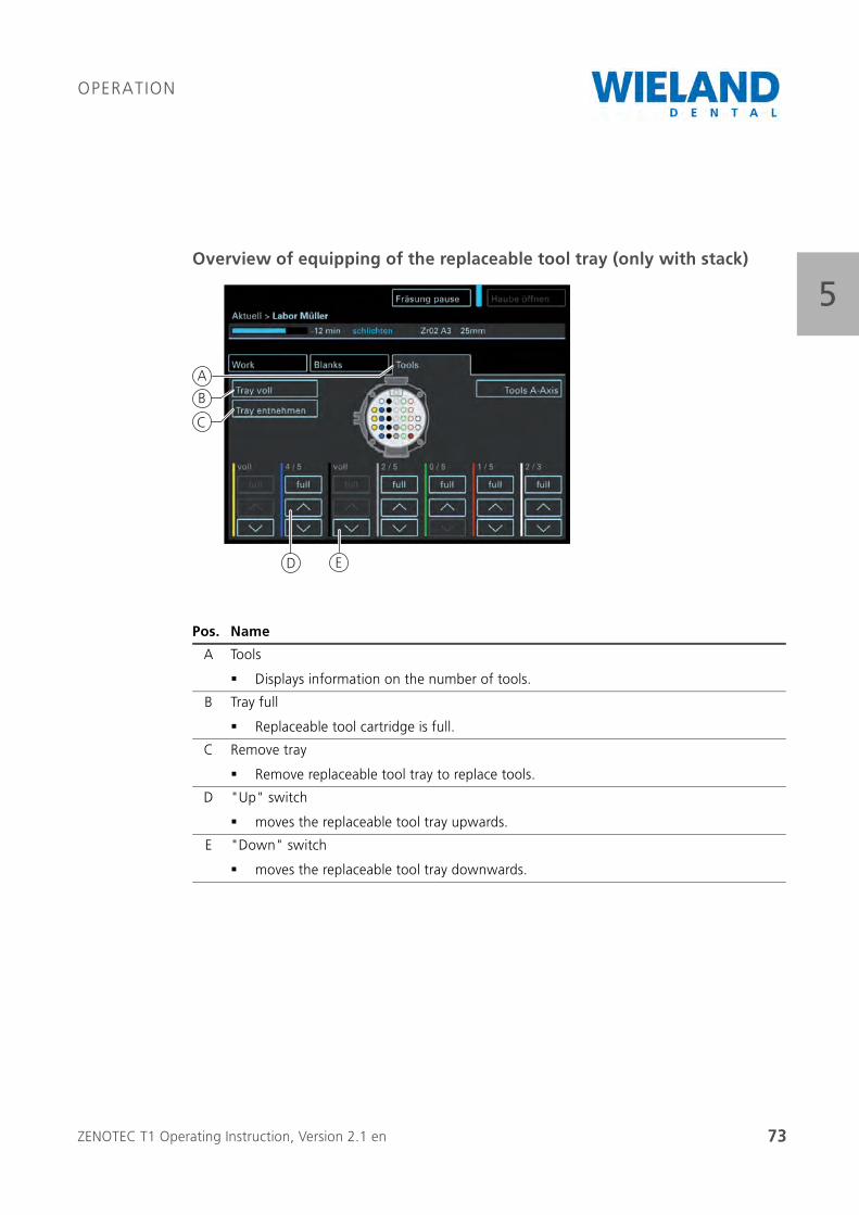
5Overview of equipping of the replaceable tool tray (only with stack)
Pos. Name
A Tools
Displays information on the number of tools.
B Tray full
Replaceable tool cartridge is full.
C Remove tray
Remove replaceable tool tray to replace tools.
D "Up" switch
moves the replaceable tool tray upwards.
E "Down" switch
moves the replaceable tool tray downwards.
ED
A
B
C

ZENOTEC T1 Operating Instruction, Version 2.1 en 74
OPERATION
5Replacing tools using the tool tray
Replacing the tools with the replaceable tool tray is only possible for milling systems with a stack.
If there is no replaceable tool tray then the tools are replaced directly at the blank holder.
WARNING
Danger due to sharp-edged tools
Cutting and stab injuries are possible.
Only handle the tool at the shaft and transport it in its original packaging.
Pos. Name
A Tray full
Replaceable tool cartridge is full.
B Remove tray
Remove replaceable tool tray to refill tools.
A
B
ZENOTEC T1 Operating Instruction, Version 2.1 en 75
OPERATION
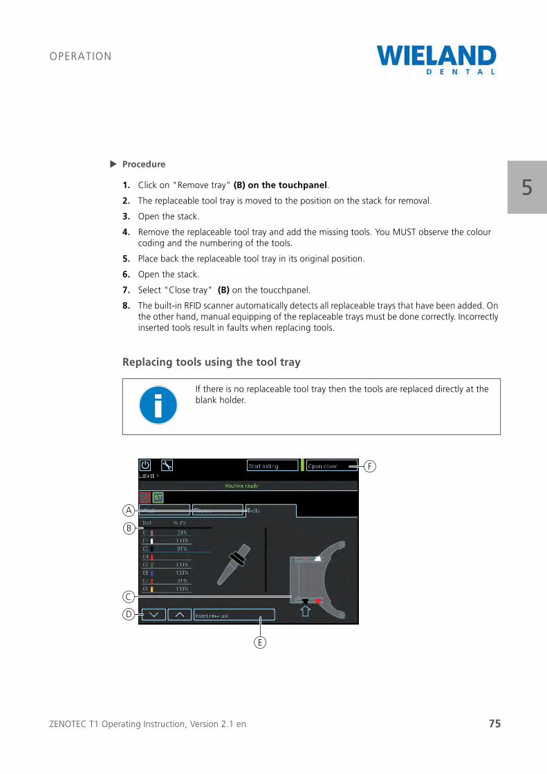
5Procedure
1. Click on "Remove tray" (B) on the touchpanel.
2. The replaceable tool tray is moved to the position on the stack for removal.
3. Open the stack.
4. Remove the replaceable tool tray and add the missing tools. You MUST observe the colour coding and the numbering of the tools.
5. Place back the replaceable tool tray in its original position.
6. Open the stack.
7. Select "Close tray" (B) on the toucchpanel.
8. The built-in RFID scanner automatically detects all replaceable trays that have been added. On the other hand, manual equipping of the replaceable trays must be done correctly. Incorrectly inserted tools result in faults when replacing tools.
Replacing tools using the tool tray
If there is no replaceable tool tray then the tools are replaced directly at the blank holder.
C
B
D
E
F
A
ZENOTEC T1 Operating Instruction, Version 2.1 en 76
OPERATION
5
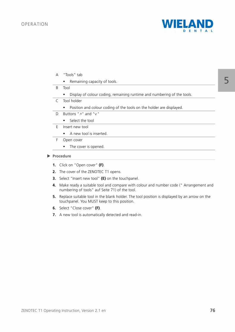
Procedure
1. Click on "Open cover" (F).
2. The cover of the ZENOTEC T1 opens.
3. Select "Insert new tool" (E) on the touchpanel.
4. Make ready a suitable tool and compare with colour and number code (" Arrangement and numbering of tools" auf Seite 71) of the tool.
5. Replace suitable tool in the blank holder. The tool position is displayed by an arrow on the touchpanel. You MUST keep to this position.
6. Select "Close cover" (F).
7. A new tool is automatically detected and read-in.
A "Tools" tab
Remaining capacity of tools.
B Tool
Display of colour coding, remaining runtime and numbering of the tools.
C Tool holder
Position and colour coding of the tools on the holder are displayed.
D Buttons " " and " "
Select the tool
E Insert new tool
A new tool is inserted.
F Open cover
The cover is opened.
<
<
ZENOTEC T1 Operating Instruction, Version 2.1 en 77
OPERATION
55.7.9 Job management
Overview of job management
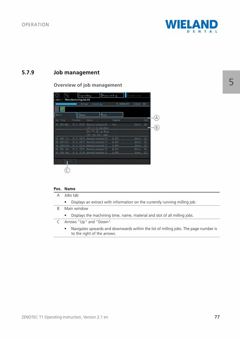
Pos. Name
A Jobs tab
Displays an extract with information on the currently running milling job.
B Main window
Displays the machining time, name, material and slot of all milling jobs.
C Arrows "Up" and "Down"
Navigates upwards and downwards within the list of milling jobs. The page number is to the right of the arrows.
C
B
A
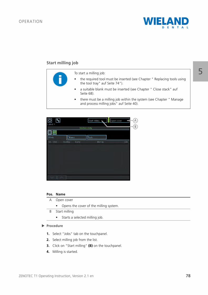
ZENOTEC T1 Operating Instruction, Version 2.1 en 78
OPERATION
5Start milling job
Procedure
1. Select "Jobs" tab on the touchpanel.
2. Select milling job from the list.
3. Click on "Start milling" (B) on the touchpanel.
4. Milling is started.
To start a milling job:
the required tool must be inserted (see Chapter " Replacing tools using the tool tray" auf Seite 74").
a suitable blank must be inserted (see Chapter " Close stack" auf Seite 68).
there must be a milling job within the system (see Chapter " Manage and process milling jobs" auf Seite 40).
Pos. Name
A Open cover
Opens the cover of the milling system.
B Start milling
Starts a selected milling job.
A
B
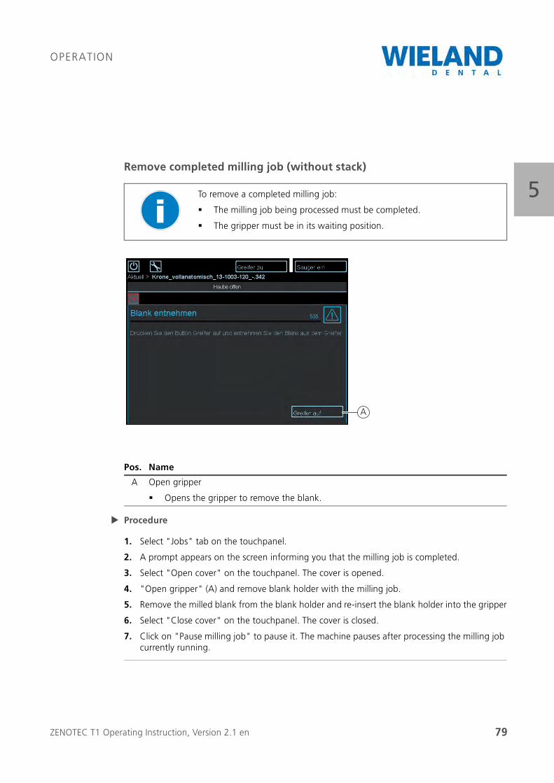
ZENOTEC T1 Operating Instruction, Version 2.1 en 79
OPERATION
5Remove completed milling job (without stack)
Procedure
1. Select "Jobs" tab on the touchpanel.
2. A prompt appears on the screen informing you that the milling job is completed.
3. Select "Open cover" on the touchpanel. The cover is opened.
4. "Open gripper" (A) and remove blank holder with the milling job.
5. Remove the milled blank from the blank holder and re-insert the blank holder into the gripper
6. Select "Close cover" on the touchpanel. The cover is closed.
7. Click on "Pause milling job" to pause it. The machine pauses after processing the milling job currently running.
To remove a completed milling job:
The milling job being processed must be completed.
The gripper must be in its waiting position.
Pos. Name
A Open gripper
Opens the gripper to remove the blank.
A
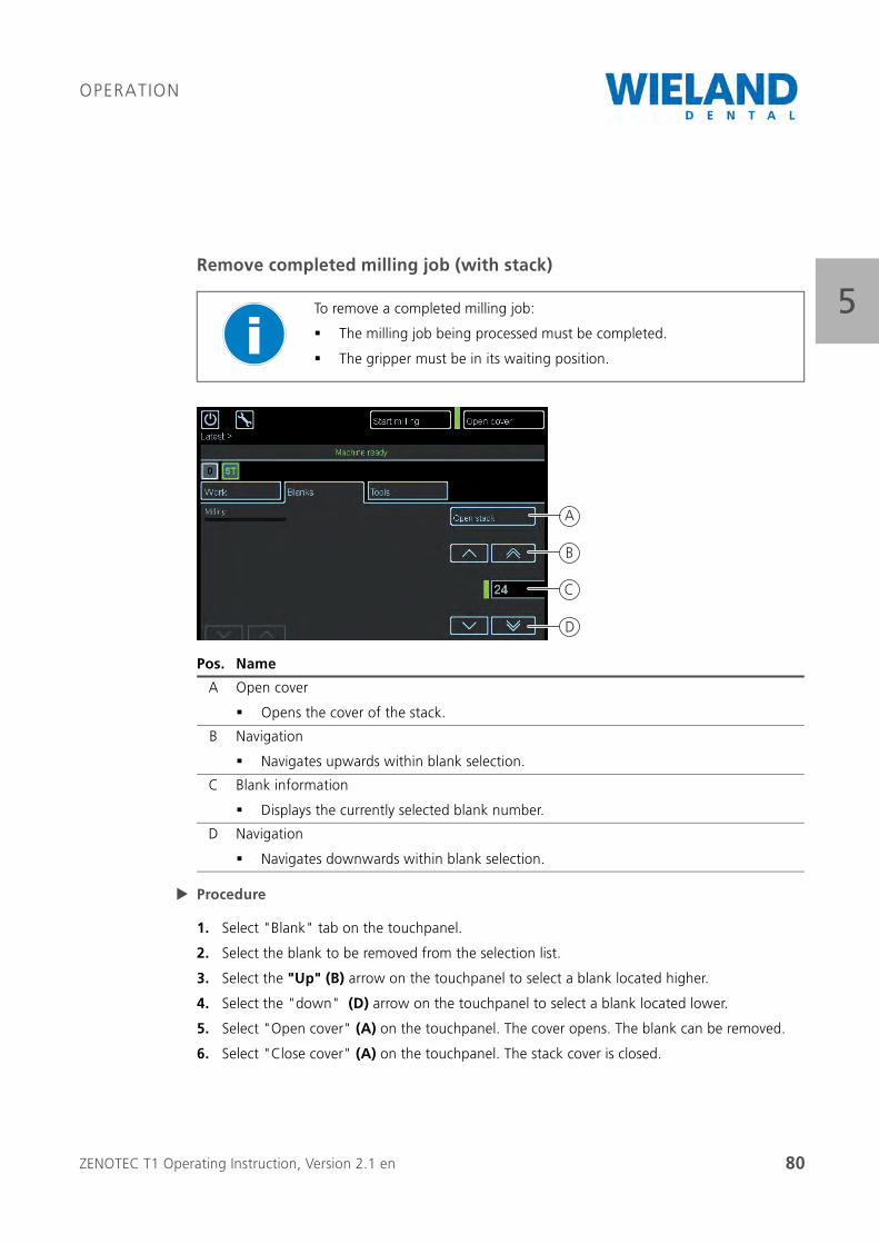
ZENOTEC T1 Operating Instruction, Version 2.1 en 80
OPERATION
5Remove completed milling job (with stack)
Procedure
1. Select "Blank" tab on the touchpanel.
2. Select the blank to be removed from the selection list.
3. Select the "Up" (B) arrow on the touchpanel to select a blank located higher.
4. Select the "down" (D) arrow on the touchpanel to select a blank located lower.
5. Select "Open cover" (A) on the touchpanel. The cover opens. The blank can be removed.
6. Select "Close cover" (A) on the touchpanel. The stack cover is closed.
To remove a completed milling job:
The milling job being processed must be completed.
The gripper must be in its waiting position.
Pos. Name
A Open cover
Opens the cover of the stack.
B Navigation
Navigates upwards within blank selection.
C Blank information
Displays the currently selected blank number.
D Navigation
Navigates downwards within blank selection.
B
C
D
A
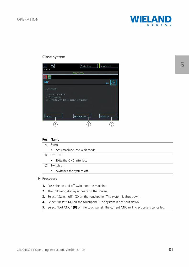
ZENOTEC T1 Operating Instruction, Version 2.1 en 81
OPERATION
5Close system
Procedure
1. Press the on and off switch on the machine.
2. The following display appears on the screen.
3. Select "Switch off" (C) on the touchpanel. The system is shut down.
4. Select "Reset" (A) on the touchpanel. The system is not shut down.
5. Select "Exit CNC" (B) on the touchpanel. The current CNC milling process is cancelled.
Pos. Name
A Reset
Sets machine into wait mode.
B Exit CNC
Exits the CNC interface
C Switch off
Switches the system off.
CBA
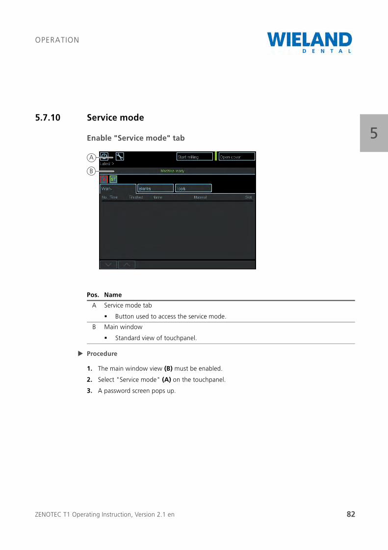
ZENOTEC T1 Operating Instruction, Version 2.1 en 82
OPERATION
55.7.10 Service mode
Enable "Service mode" tab
Procedure
1. The main window view (B) must be enabled.
2. Select "Service mode" (A) on the touchpanel.
3. A password screen pops up.
Pos. Name
A Service mode tab
Button used to access the service mode.
B Main window
Standard view of touchpanel.
B
A
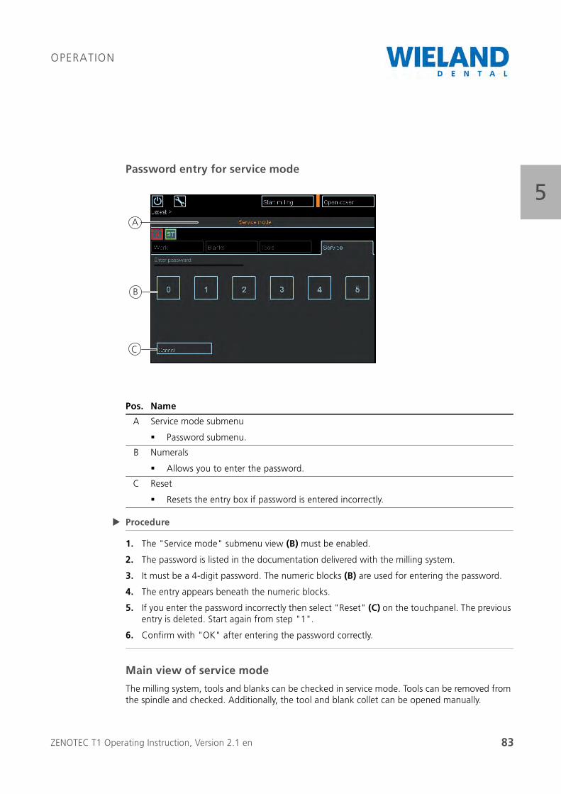
ZENOTEC T1 Operating Instruction, Version 2.1 en 83
OPERATION
5Password entry for service mode
Procedure
1. The "Service mode" submenu view (B) must be enabled.
2. The password is listed in the documentation delivered with the milling system.
3. It must be a 4-digit password. The numeric blocks (B) are used for entering the password.
4. The entry appears beneath the numeric blocks.
5. If you enter the password incorrectly then select "Reset" (C) on the touchpanel. The previous entry is deleted. Start again from step "1".
6. Confirm with "OK" after entering the password correctly.
Main view of service mode
The milling system, tools and blanks can be checked in service mode. Tools can be removed from the spindle and checked. Additionally, the tool and blank collet can be opened manually.
Pos. Name
A Service mode submenu
Password submenu.
B Numerals
Allows you to enter the password.
C Reset
Resets the entry box if password is entered incorrectly.
A
B
C
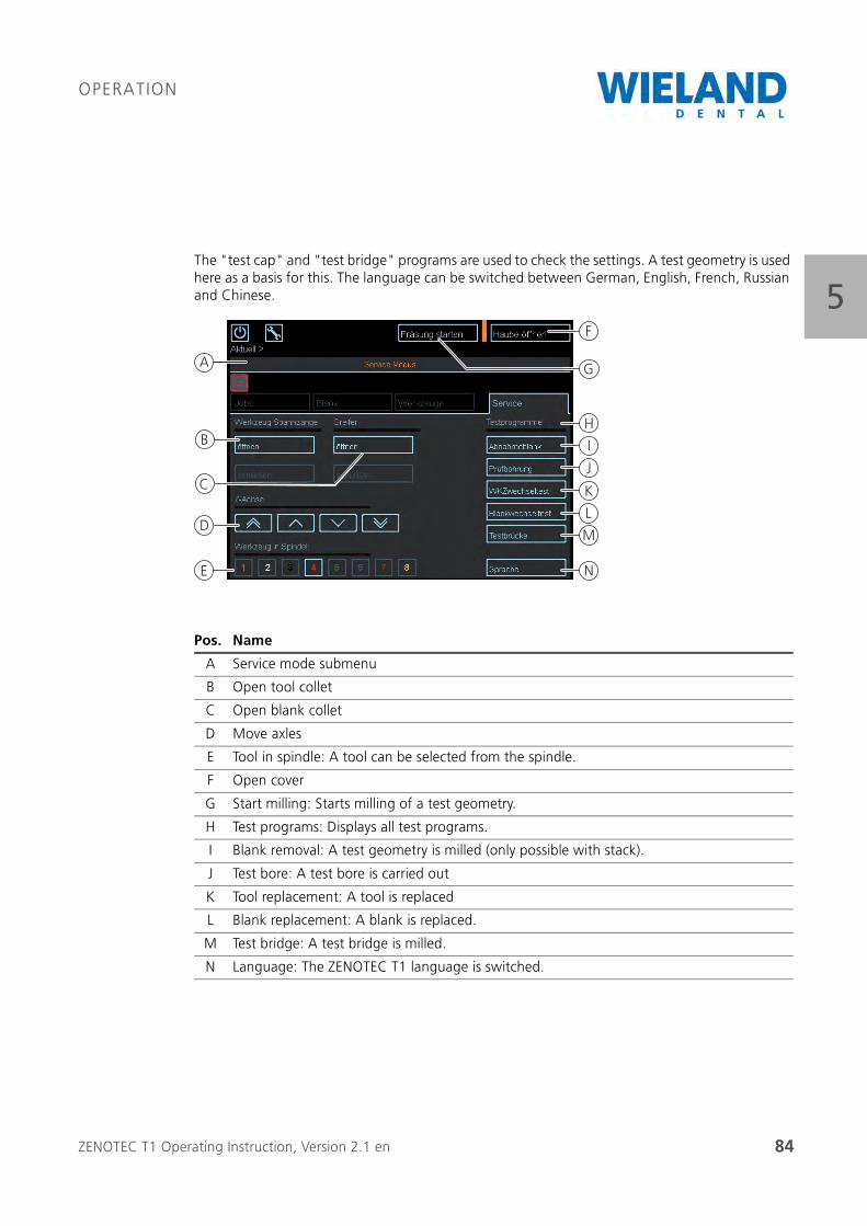
ZENOTEC T1 Operating Instruction, Version 2.1 en 84
OPERATION
5The "test cap" and "test bridge" programs are used to check the settings. A test geometry is used here as a basis for this. The language can be switched between German, English, French, Russian and Chinese.
Pos. Name
A Service mode submenu
B Open tool collet
C Open blank collet
D Move axles
E Tool in spindle: A tool can be selected from the spindle.
F Open cover
G Start milling: Starts milling of a test geometry.
H Test programs: Displays all test programs.
I Blank removal: A test geometry is milled (only possible with stack).
J Test bore: A test bore is carried out
K Tool replacement: A tool is replaced
L Blank replacement: A blank is replaced.
M Test bridge: A test bridge is milled.
N Language: The ZENOTEC T1 language is switched.
A
F
H
I
J
K
L
M
N
G
B
D
E
C
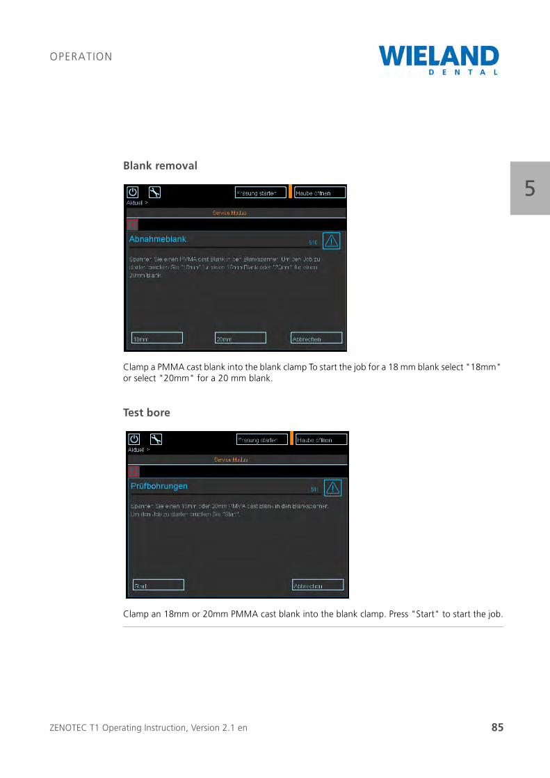
ZENOTEC T1 Operating Instruction, Version 2.1 en 85
OPERATION
5Blank removal
Clamp a PMMA cast blank into the blank clamp To start the job for a 18 mm blank select "18mm" or select "20mm" for a 20 mm blank.
Test bore
Clamp an 18mm or 20mm PMMA cast blank into the blank clamp. Press "Start" to start the job.
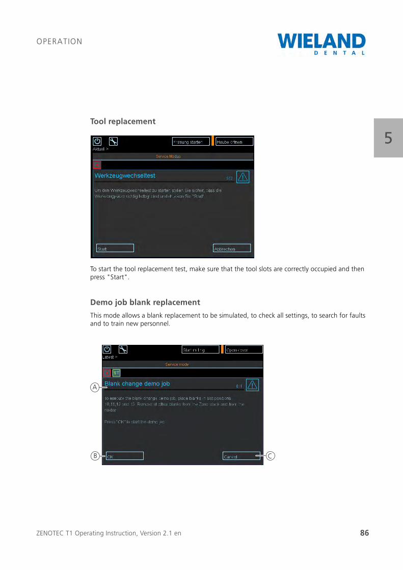
ZENOTEC T1 Operating Instruction, Version 2.1 en 86
OPERATION
5Tool replacement
To start the tool replacement test, make sure that the tool slots are correctly occupied and then press "Start".
Demo job blank replacement
This mode allows a blank replacement to be simulated, to check all settings, to search for faults and to train new personnel.
A
B C
ZENOTEC T1 Operating Instruction, Version 2.1 en 87
OPERATION
5
Procedure
1. Select "Blank replacement" (K) on the touchpanel.
2. A submenu for the demo mode opens.
3. Remove all blanks from stack.
4. Insert a blank in slots 10, 11, 12 and 13.
5. Press "Ok" (B) on the touchpanel. The demo job starts.
6. To cancel the demo job before it is completed, press "Cancel" (C) on the touchpanel.
Pos. Name
A Blank replacement tab
A demo job is started.
B OK
The demo job is confirmed.
C Cancel
The demo job is cancelled.
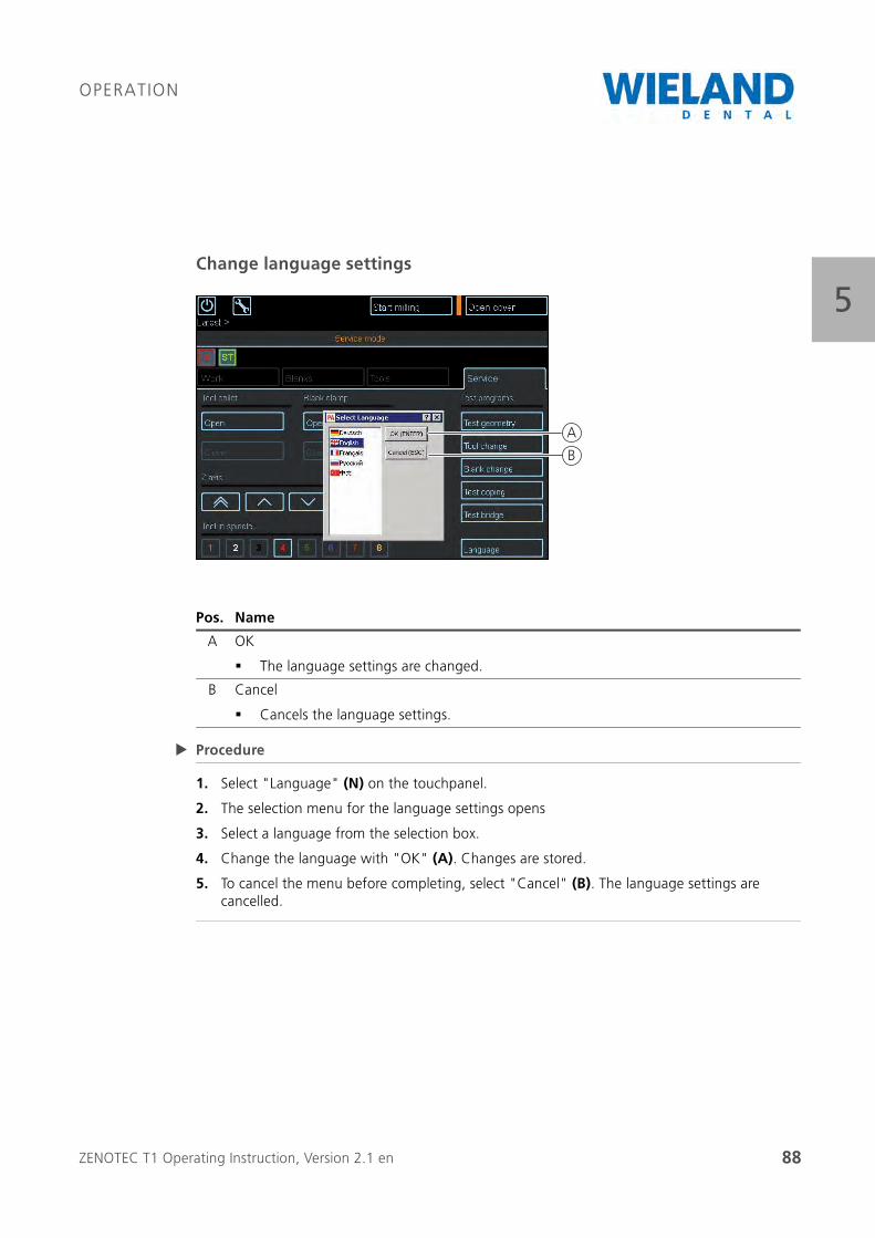
ZENOTEC T1 Operating Instruction, Version 2.1 en 88
OPERATION
5Change language settings
Procedure
1. Select "Language" (N) on the touchpanel.
2. The selection menu for the language settings opens
3. Select a language from the selection box.
4. Change the language with "OK" (A). Changes are stored.
5. To cancel the menu before completing, select "Cancel" (B). The language settings are cancelled.
Pos. Name
A OK
The language settings are changed.
B Cancel
Cancels the language settings.
B
A
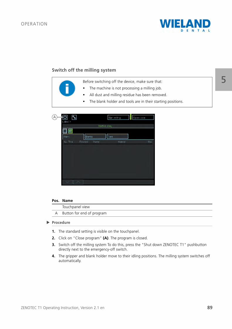
ZENOTEC T1 Operating Instruction, Version 2.1 en 89
OPERATION
5Switch off the milling system
Procedure
1. The standard setting is visible on the touchpanel.
2. Click on "Close program" (A). The program is closed.
3. Switch off the milling system To do this, press the "Shut down ZENOTEC T1" pushbutton directly next to the emergency-off switch.
4. The gripper and blank holder move to their idling positions. The milling system switches off automatically.
Before switching off the device, make sure that:
The machine is not processing a milling job.
All dust and milling residue has been removed.
The blank holder and tools are in their starting positions.
Pos. Name
Touchpanel view
A Button for end of program
A

ZENOTEC T1 Operating Instruction, Version 2.1 en 90
OPERATION
5
ZENOTEC T1 Operating Instruction, Version 2.1 en 91
FAULTS
66 Faults
The manufacturer must be informed of all faults, irrespective of their type. All forms of mainte-nance work may only be carried out by authorised and trained personnel. The system must be disconnected from the power supply during troubleshooting and when remedying faults. Hazard zones are possible, especially from moving tools, movements during automatic replacement of tools and axle movements of the spindle.
If faults occur during operation then you must:
inform WIELAND Dental + Technik GmbH & Co. KG of this.
disconnect the machine from the power supply and
make sure that only authorised expert personnel carry out troubleshoot-ing and remedy the fault.
CAREFUL
Troubleshooting and fault remedy only by authorised expert personnel.
DANGER
Disconnect the system from the power supply before opening the machine housing:
Pull the mains plug
DANGER
Disconnect the system from the power supply and the compressed-air feed before opening the stack:
Pull the mains plug.
Disconnect the compressed air (pneumatic) feed.
ZENOTEC T1 Operating Instruction, Version 2.1 en 92
FAULTS
6
Contact information for service and enquiries
For all of your questions regarding the ZENOTEC T1 milling system please contact:
6.1 Remedying faults
The following table provides a list of faults, especially those that may occur when starting the ZENOTEC T1 system. If the milling system can not be started by the measures described then you must contact a member of the service staff of WIELAND Dental + Technik GmbH & Co. KG.
WARNING
Danger due to moving machine parts when the machine is switched on
Serious crushing and cutting injuries possible if cover is not closed.
Only have maintenance work carried out by authorised and trained personnel.
WARNING
Open electrical connections
Lethal or severe injuries possible
Only have troubleshooting and repair work carried out by authorised expert personnel. Disconnect from mains during this work.
WIELAND Dental + Technik GmbH & Co. KG
Schwenninger Straße 13
75179 Pforzheim
Germany
ZENOTEC Support
National call: 08 00 / 93 66 823
International call: +49 72 31 / 37 05 400
Fax: 0 72 31 / 35 79 59
E-mail: [email protected]
www.wieland-dental.de
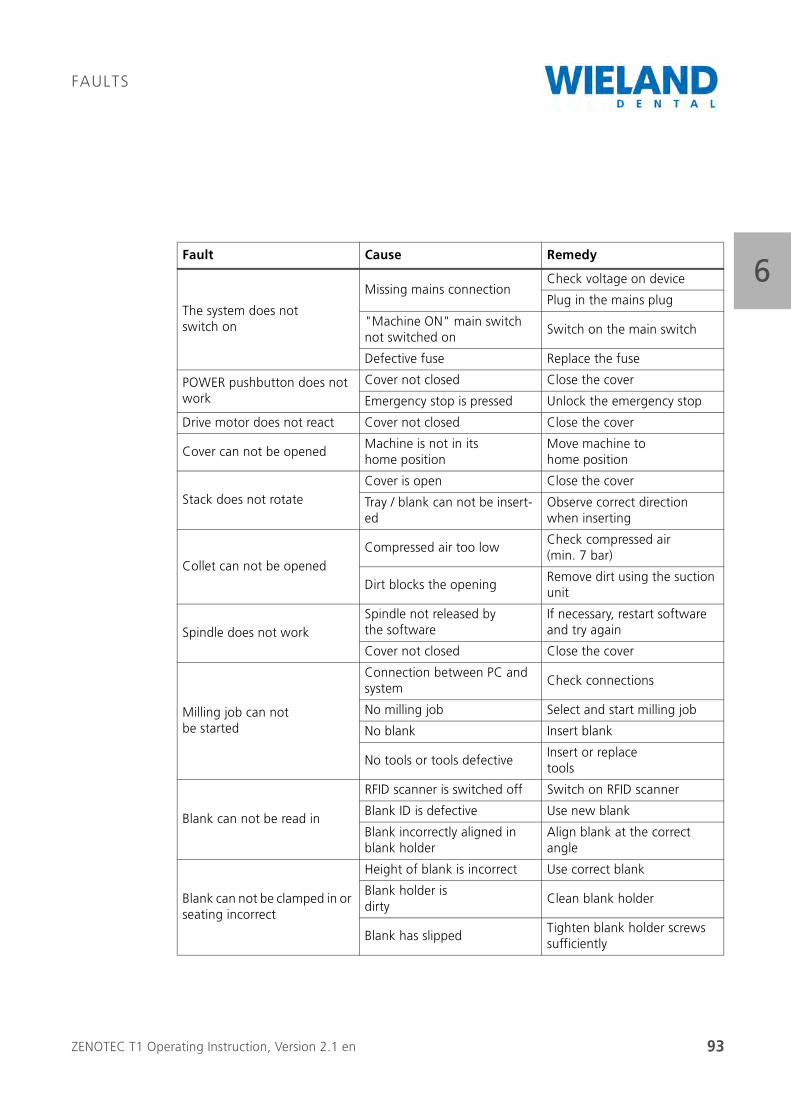
ZENOTEC T1 Operating Instruction, Version 2.1 en 93
FAULTS
6Fault Cause Remedy
The system does notswitch on
Missing mains connectionCheck voltage on device
Plug in the mains plug
"Machine ON" main switch not switched on
Switch on the main switch
Defective fuse Replace the fuse
POWER pushbutton does not work
Cover not closed Close the cover
Emergency stop is pressed Unlock the emergency stop
Drive motor does not react Cover not closed Close the cover
Cover can not be openedMachine is not in its home position
Move machine to home position
Stack does not rotateCover is open Close the cover
Tray / blank can not be insert-ed
Observe correct direction when inserting
Collet can not be openedCompressed air too low
Check compressed air(min. 7 bar)
Dirt blocks the openingRemove dirt using the suction unit
Spindle does not workSpindle not released by the software
If necessary, restart software and try again
Cover not closed Close the cover
Milling job can not be started
Connection between PC and system
Check connections
No milling job Select and start milling job
No blank Insert blank
No tools or tools defectiveInsert or replace tools
Blank can not be read in
RFID scanner is switched off Switch on RFID scanner
Blank ID is defective Use new blank
Blank incorrectly aligned in blank holder
Align blank at the correct angle
Blank can not be clamped in or seating incorrect
Height of blank is incorrect Use correct blank
Blank holder is dirty
Clean blank holder
Blank has slippedTighten blank holder screws sufficiently
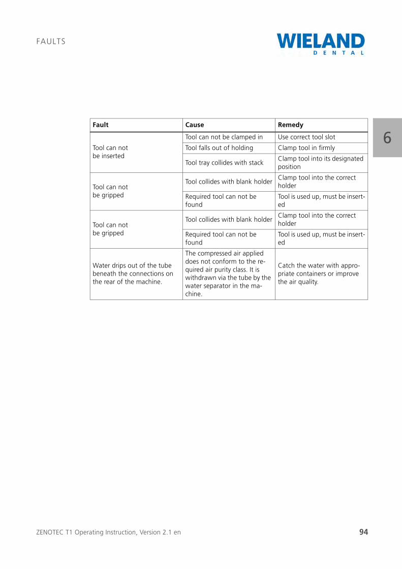
ZENOTEC T1 Operating Instruction, Version 2.1 en 94
FAULTS
6Tool can not be inserted
Tool can not be clamped in Use correct tool slot
Tool falls out of holding Clamp tool in firmly
Tool tray collides with stackClamp tool into its designated position
Tool can not be gripped
Tool collides with blank holderClamp tool into the correct holder
Required tool can not be found
Tool is used up, must be insert-ed
Tool can not be gripped
Tool collides with blank holderClamp tool into the correct holder
Required tool can not be found
Tool is used up, must be insert-ed
Water drips out of the tube beneath the connections on the rear of the machine.
The compressed air applied does not conform to the re-quired air purity class. It is withdrawn via the tube by the water separator in the ma-chine.
Catch the water with appro-priate containers or improve the air quality.
Fault Cause Remedy
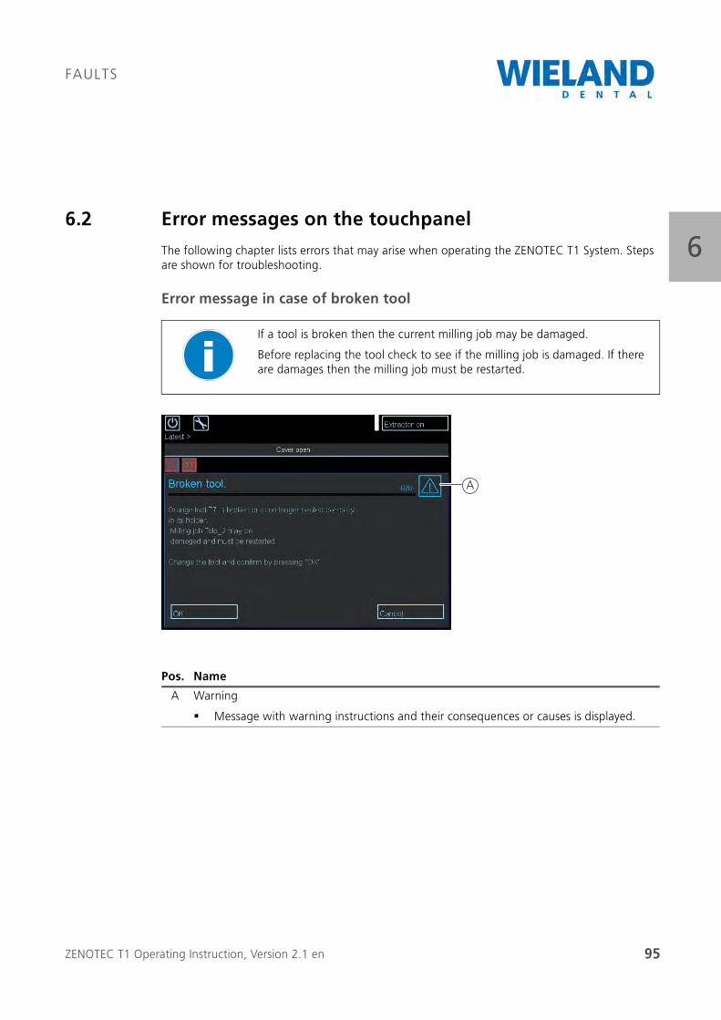
ZENOTEC T1 Operating Instruction, Version 2.1 en 95
FAULTS
66.2 Error messages on the touchpanel
The following chapter lists errors that may arise when operating the ZENOTEC T1 System. Steps are shown for troubleshooting.
Error message in case of broken tool
If a tool is broken then the current milling job may be damaged.
Before replacing the tool check to see if the milling job is damaged. If there are damages then the milling job must be restarted.
Pos. Name
A Warning
Message with warning instructions and their consequences or causes is displayed.
A
ZENOTEC T1 Operating Instruction, Version 2.1 en 96
FAULTS
6Procedure
1. Error message in case of broken tool appears
2. A message appears under the warning displaying the colour coding of the tool
3. If the milled object is damaged then select "Reject milled object" (C) on the touchpanel.
4. The correct tool must be in readiness.
5. Press "Open cover" (B) on the touchpanel. The cover opens.
6. Replace the tool with suitable colour coding
7. Press "Close cover" (B) on the touchpanel. The cover closes.
8. A new milling job can be started.
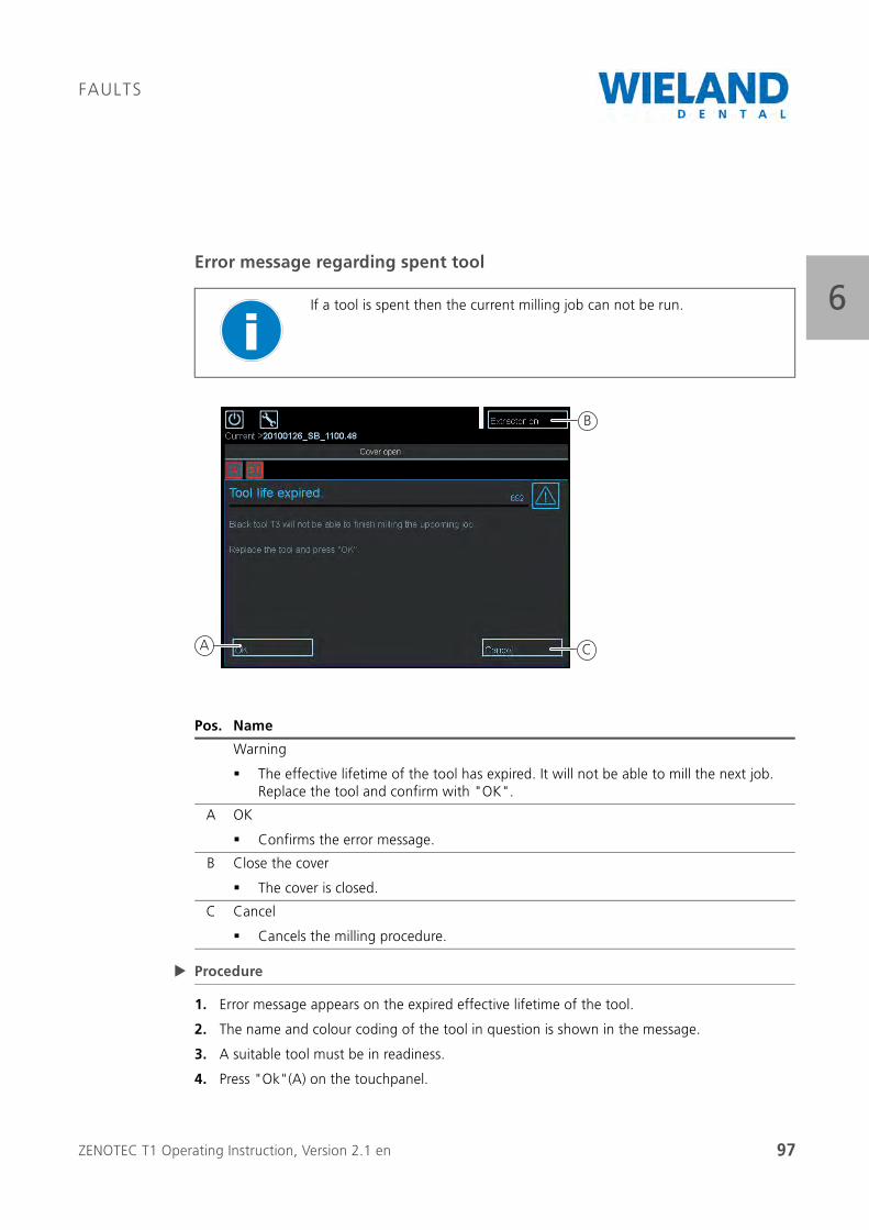
ZENOTEC T1 Operating Instruction, Version 2.1 en 97
FAULTS
6Error message regarding spent tool
Procedure
1. Error message appears on the expired effective lifetime of the tool.
2. The name and colour coding of the tool in question is shown in the message.
3. A suitable tool must be in readiness.
4. Press "Ok"(A) on the touchpanel.
If a tool is spent then the current milling job can not be run.
Pos. Name
Warning
The effective lifetime of the tool has expired. It will not be able to mill the next job. Replace the tool and confirm with "OK".
A OK
Confirms the error message.
B Close the cover
The cover is closed.
C Cancel
Cancels the milling procedure.
A C
B
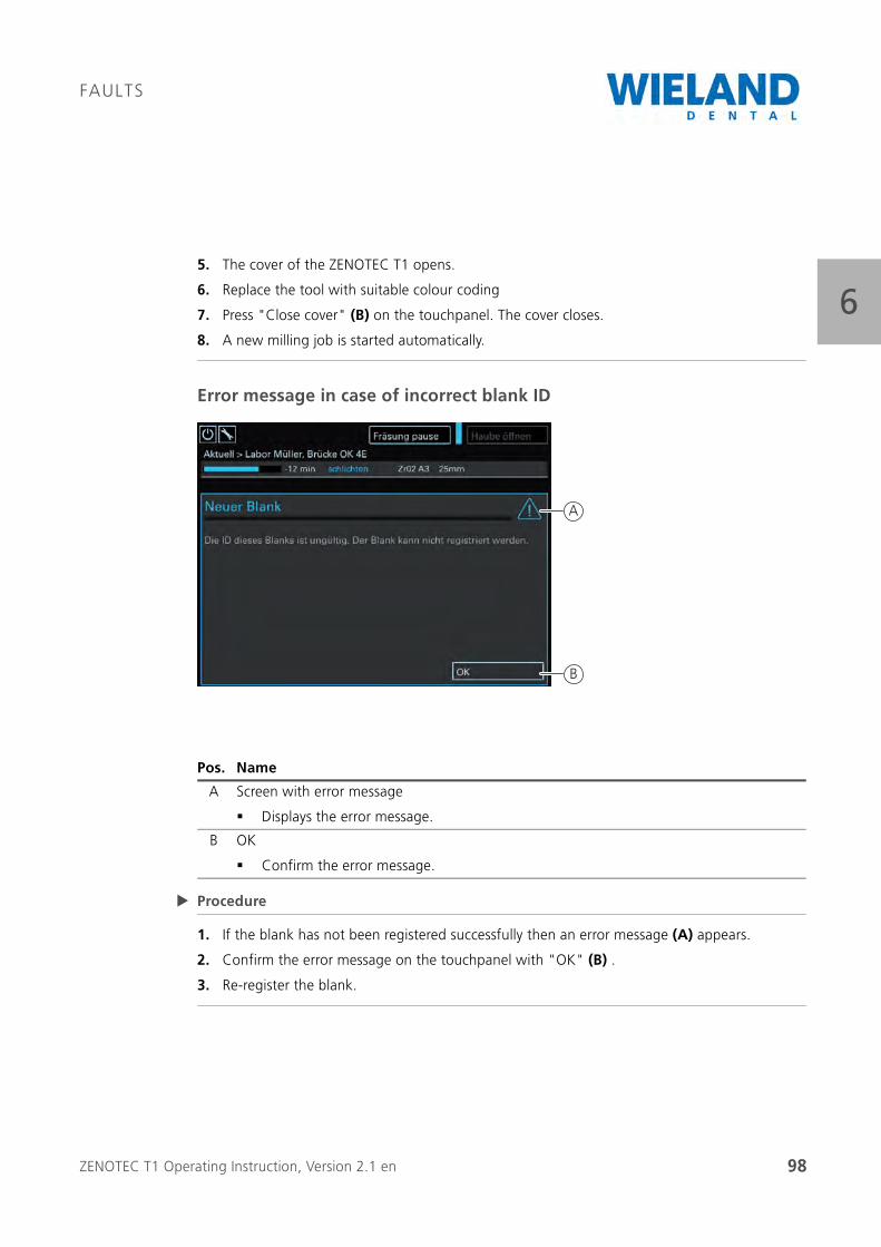
ZENOTEC T1 Operating Instruction, Version 2.1 en 98
FAULTS
65. The cover of the ZENOTEC T1 opens.
6. Replace the tool with suitable colour coding
7. Press "Close cover" (B) on the touchpanel. The cover closes.
8. A new milling job is started automatically.
Error message in case of incorrect blank ID
Procedure
1. If the blank has not been registered successfully then an error message (A) appears.
2. Confirm the error message on the touchpanel with "OK" (B) .
3. Re-register the blank.
Pos. Name
A Screen with error message
Displays the error message.
B OK
Confirm the error message.
B
A
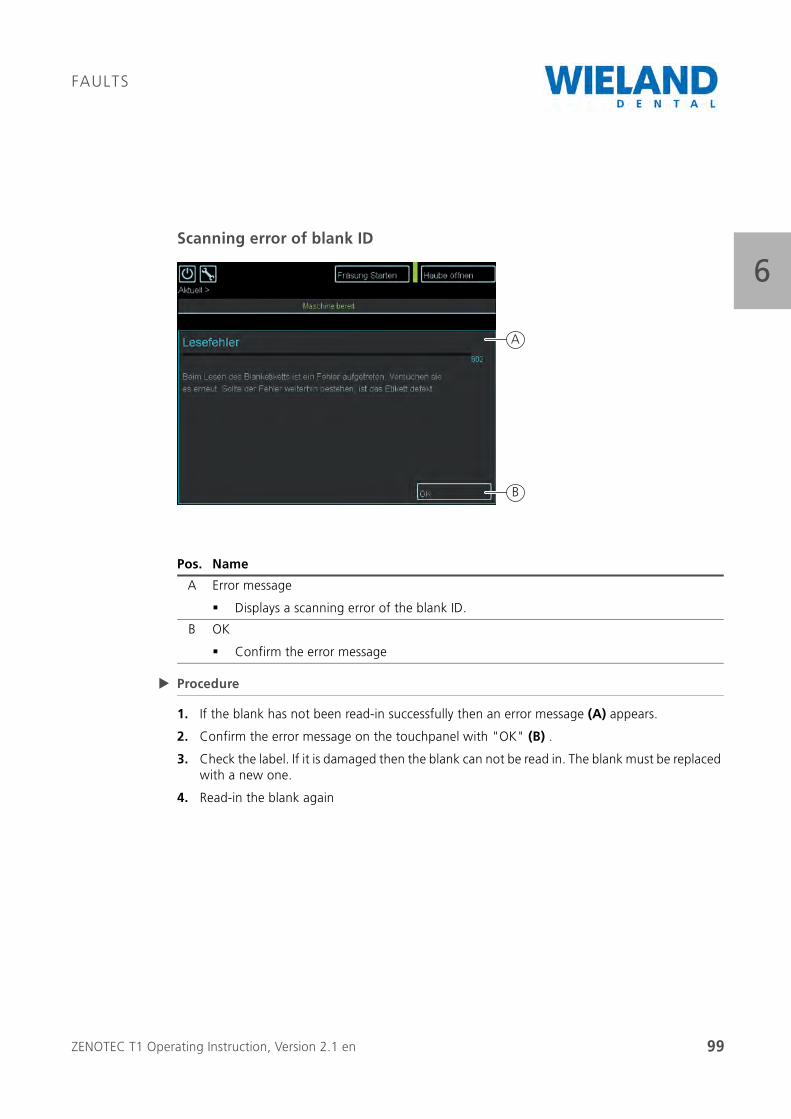
ZENOTEC T1 Operating Instruction, Version 2.1 en 99
FAULTS
6Scanning error of blank ID
Procedure
1. If the blank has not been read-in successfully then an error message (A) appears.
2. Confirm the error message on the touchpanel with "OK" (B) .
3. Check the label. If it is damaged then the blank can not be read in. The blank must be replaced with a new one.
4. Read-in the blank again
Pos. Name
A Error message
Displays a scanning error of the blank ID.
B OK
Confirm the error message
B
A
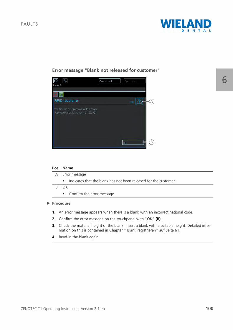
ZENOTEC T1 Operating Instruction, Version 2.1 en 100
FAULTS
6Error message "Blank not released for customer"
Procedure
1. An error message appears when there is a blank with an incorrect national code.
2. Confirm the error message on the touchpanel with "OK" (B) .
3. Check the material height of the blank. Insert a blank with a suitable height. Detailed infor-mation on this is contained in Chapter " Blank registrieren" auf Seite 61.
4. Read-in the blank again
Pos. Name
A Error message
Indicates that the blank has not been released for the customer.
B OK
Confirm the error message.
B
A
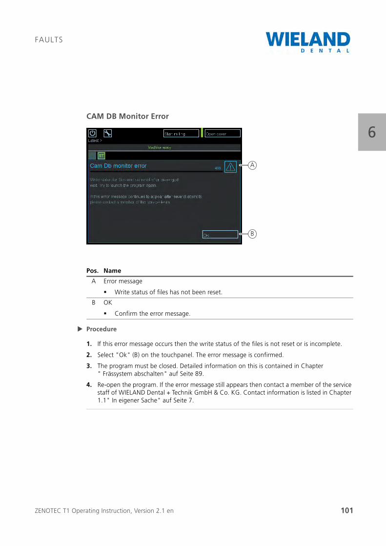
ZENOTEC T1 Operating Instruction, Version 2.1 en 101
FAULTS
6CAM DB Monitor Error
Procedure
1. If this error message occurs then the write status of the files is not reset or is incomplete.
2. Select "Ok" (B) on the touchpanel. The error message is confirmed.
3. The program must be closed. Detailed information on this is contained in Chapter " Frässystem abschalten" auf Seite 89.
4. Re-open the program. If the error message still appears then contact a member of the service staff of WIELAND Dental + Technik GmbH & Co. KG. Contact information is listed in Chapter 1.1" In eigener Sache" auf Seite 7.
Pos. Name
A Error message
Write status of files has not been reset.
B OK
Confirm the error message.
B
A
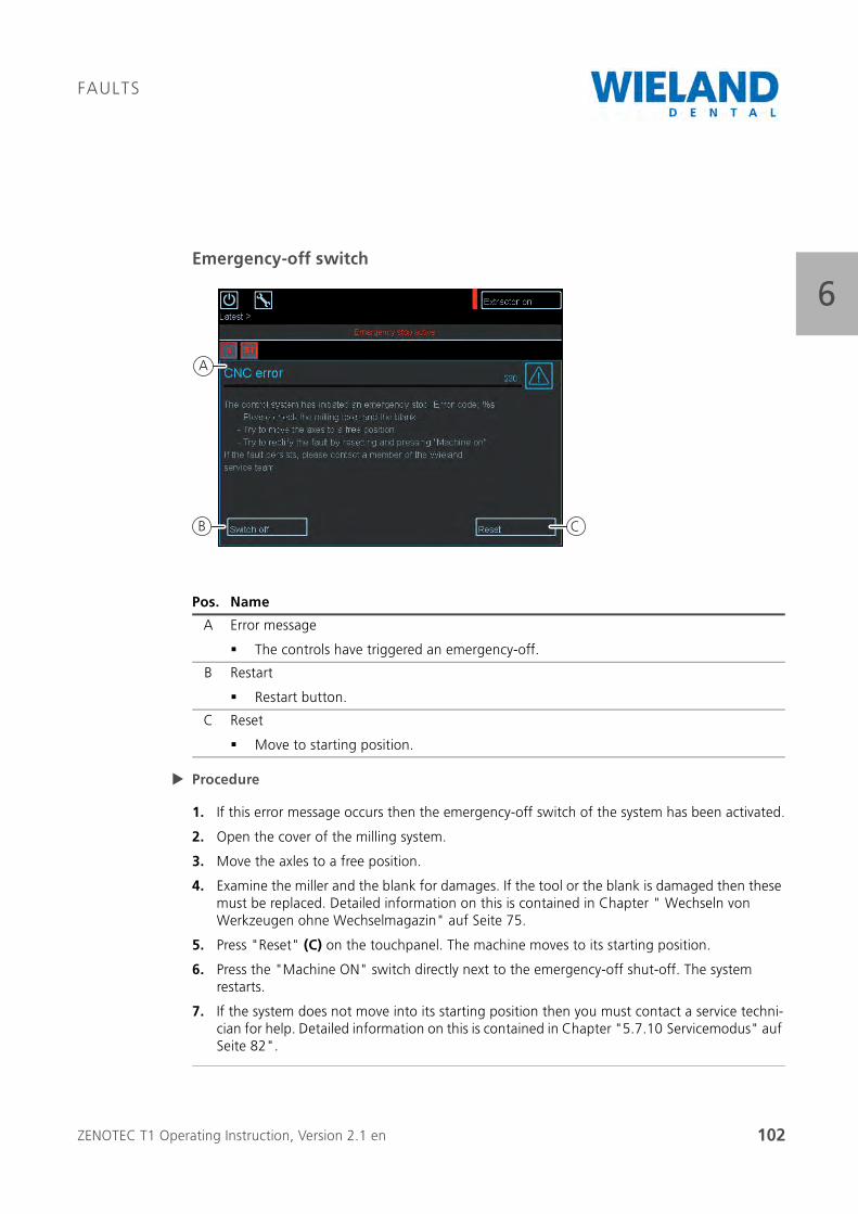
ZENOTEC T1 Operating Instruction, Version 2.1 en 102
FAULTS
6Emergency-off switch
Procedure
1. If this error message occurs then the emergency-off switch of the system has been activated.
2. Open the cover of the milling system.
3. Move the axles to a free position.
4. Examine the miller and the blank for damages. If the tool or the blank is damaged then these must be replaced. Detailed information on this is contained in Chapter " Wechseln von Werkzeugen ohne Wechselmagazin" auf Seite 75.
5. Press "Reset" (C) on the touchpanel. The machine moves to its starting position.
6. Press the "Machine ON" switch directly next to the emergency-off shut-off. The system restarts.
7. If the system does not move into its starting position then you must contact a service techni-cian for help. Detailed information on this is contained in Chapter "5.7.10 Servicemodus" auf Seite 82".
Pos. Name
A Error message
The controls have triggered an emergency-off.
B Restart
Restart button.
C Reset
Move to starting position.
A
B C
ZENOTEC T1 Operating Instruction, Version 2.1 en 103
FAULTS
66.3 FAQ / Frequently Asked Questions
Stack can not be opened
The stack can only be opened when the milling system is in ready-for-operation mode. To open the stack, read through « Blank registrieren» auf Seite 61 in the "Operation" chapter.

ZENOTEC T1 Operating Instruction, Version 2.1 en 104
FAULTS
6
ZENOTEC T1 Operating Instruction, Version 2.1 en 105
CLEANING
77 Cleaning
7.1 General information
Regular cleaning and maintenance increases the operational safety of the machine as well as its lifetime.
Before cleaning and maintenance work, switch off the main switch of the machine and pull the mains plug to prevent accidental switch on.
Even if the main switch is switched off, pats of the electrical system still remain live. Please wait a few minutes before commencing with maintenance.
Please observe the safety instructions!
7.2 Using cleaning agents
Cleaning agent
Cleaning agent that attacks plastics, rubber or paints must not be used. They could damage hoses (pneumatics), cable and seals.
Cleaning agent may contain substances harmful to health. Observe the instructions of the manu-facturer.
WARNING
Observe the safety instructions in the maintenance instructions
Only carry out maintenance and cleaning work when the machine is switched off
WARNING
Periodic checking of electrical installation
Maintenance interval: Annual
Have defective cable replaced immediately by maintenance personnel
ZENOTEC T1 Operating Instruction, Version 2.1 en 106
CLEANING
77.3 General cleanliness
As with all high-quality technical devices, value should be placed on cleanliness because this increases the lifetime of the single components and prevents malfunctions. You should therefore regularly clean the machine with a vacuum cleaner. Make sure that no dirt penetrates into the mechanical components of the machine. The glass plates and synthetic surface can be cleaned using a non-abrasive liquid cleanser.
The following components must therefore be tested and cleaned at least once per day and if used additionally at night must be checked at least twice per day (mornings and evenings):
Milling chamber with blank holder fixture
Tools and their holding fixtures
Spindle with blank collet
If installed, the stack with blank holder fixtures
The cleaning recommendation for the single components is as follows.
Blank holder:
The blank holder and its clamping ring must be free of all chippings and dust before inserting the blank to ensure optimum clamping. We recommend you use a suitable brush for this. The screws and thread must also be kept clean. The blank holders must always be kept dry. The interface to the blank gripper should be checked for soiling each time before it is used in the machine and should be cleaned when required.
Blank holder and tool holder
To ensure perfect replacement of the tool and the blank, both the blank holder fixture and the tool holder as well as the blank clamp (gripper) must be kept free of dust, wear and chippings. Defective or spent tool holders must be replaced. In this case, please contact the service depart-ment
Tools:
The tool shafts must be checked for soiling and cleaned as required. Only then can trouble-free tool replacement be guaranteed.
CAREFUL
Keep the working area and its environment clean.
Periodic function check of the gas-filled shock absorber; maintenance interval: Monthly
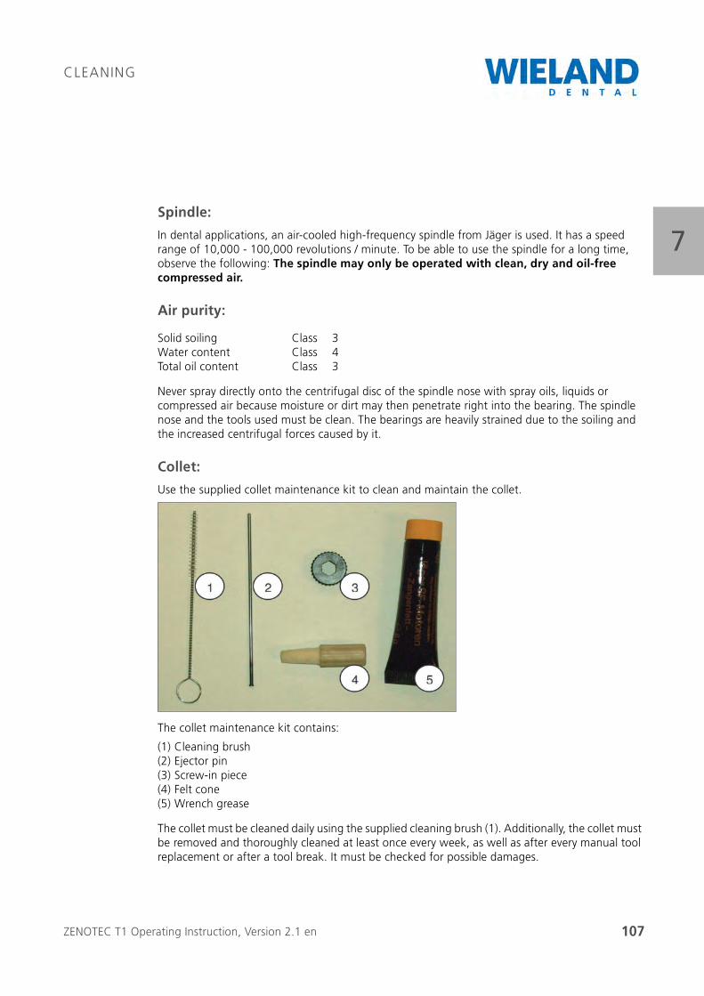
ZENOTEC T1 Operating Instruction, Version 2.1 en 107
CLEANING
7Spindle:
In dental applications, an air-cooled high-frequency spindle from Jäger is used. It has a speed range of 10,000 - 100,000 revolutions / minute. To be able to use the spindle for a long time, observe the following: The spindle may only be operated with clean, dry and oil-free compressed air.
Air purity:
Never spray directly onto the centrifugal disc of the spindle nose with spray oils, liquids or compressed air because moisture or dirt may then penetrate right into the bearing. The spindle nose and the tools used must be clean. The bearings are heavily strained due to the soiling and the increased centrifugal forces caused by it.
Collet:
Use the supplied collet maintenance kit to clean and maintain the collet.
The collet maintenance kit contains:
The collet must be cleaned daily using the supplied cleaning brush (1). Additionally, the collet must be removed and thoroughly cleaned at least once every week, as well as after every manual tool replacement or after a tool break. It must be checked for possible damages.
Solid soiling Class 3Water content Class 4Total oil content Class 3
(1) Cleaning brush(2) Ejector pin(3) Screw-in piece(4) Felt cone(5) Wrench grease
ZENOTEC T1 Operating Instruction, Version 2.1 en 108
CLEANING
7Important: The collet must never be closed when a tool is not inserted! If the spindle rotates without a tool then it may be destroyed!
Cleaning the collet:
Procedure
1. Make sure that the spindle does not rotate. Open the collet with the "Open/Close collet" button and make sure that the tool in the spindle does not fall out.
2. Now remove the tool from the collet. Unscrew the collet from the spindle using the screw-in piece (3) .
3. Clean the collet fixture in the spindle using the felt cone designed for this (4). Clean the collet using the brush intended for this (1). Make sure that there is no dirt in the collet and that it is not soiled during the procedure. If a tool breaks and part of it remains in the collet then you can remove this using the ejector pin (2).
4. Coat the cone of the collet with a light film of grease (wrench grease) (5). Screw the collet manually back into the spindle.
5. The collet must be screwed in right up to the stop but may only be tightened hand-tight. If the collet can not be turned manually up to the stop then please use the screw-in piece. Place the previously removed tool back into the spindle.
6. Now press the "Open / Close collet" button to fix the inserted tool into the collet.
7. The newly inserted tool must then be aligned. For this procedure, click on the "Align tool" button. The spindle is now ready for operation.
ZENOTEC Zr Disc: The ZENOTEC Zr Disc may only be milled when milling dust is simultaneously sucked off by a suitable suction unit. Only specially approved tools may be used for the ZENOTEC Zr Disc.
Water separator: The water separator is behind the rear machine cover and is maintenance free.
For cleaning and maintaining the spindle, the manual supplied by the spindle manufacturer (Jäger) must be read and observed. It contains additional useful tips for trouble-free, longlife operation of the spindle.
ZENOTEC T1 Operating Instruction, Version 2.1 en 109
MAINTENANCE
88 Maintenance
8.1 Checklist
Carry out before each machine start:
Clean machine chamber, tool holders, tool shafts of all tools; check compressed air according to the instructions
Daily maintenance
Clean collet with the supplied cleaning brush (spindle maintenance kit)
Weekly maintenance (also to be carried out after a tool break)
Remove collet, clean, check for damages and slightly grease the cone
Clean collet fixture on the spindle using the supplied felt cone
ZENOTEC T1 Operating Instruction, Version 2.1 en 110
MAINTENANCE
8
ZENOTEC T1 Operating Instruction, Version 2.1 en 111
REPAIRS
99 Repairs
Have repair work carried out by authorised expert personnel from
WIELAND Dental + Technik GmbH & Co. KG.
WARNING
Danger when opening the machine housing
Death or gravest injury possible due to electrical shock.
Do not open the machine housing. Only have repairs carried out by autho-rised expert personnel.

ZENOTEC T1 Operating Instruction, Version 2.1 en 112
REPAIRS
9

ZENOTEC® T1 Operating Instructions, Version 2.1 en 113
10
5450
14e.
01.0
1/12
EXPECT THE DIFFERENCE! BY WIELAND.
As a major supplier of dental system solutions, WIELAND embodies both tradition and progress
in matters of dental products and technology. Since our company was founded in 1871, we have
stayed true to our corporate philosophy of combining tradition, innovation and quality with the
best in customer care. Today, our core competencies and key strengths lie in the forward-looking
integration of technologies and materials for dental prosthetics. This ensures that patients can
trust in the quality of their restorations, and our partners in dental practices and laboratories
can continue with confidence on the path to digitalisation and greater competitiveness.
WIELAND offers a wide range of products and services from CAD/CAM technologies and
dental alloys to veneering ceramics and electroforming. Thanks to our worldwide presence and
international network, WIELAND is never far away, and your contact person can always be located
via the Internet.
WIELAND Dental +Technik GmbH & Co. KG
Schwenninger Straße 13, 75179 Pforzheim, Germany
Fon +49 72 31/37 05-0, Fax +49 72 31/35 79 59
D E N T A L
www.wieland-dental.de