Embed Size (px)
Citation preview

ZEN-RTU-MINI-MAN-17V01 (0202) Copyright © 2017 Define Instruments
1
Zen RTU MiniRemote Terminal Unit
› 4, 12, or 16 Universal Isolated InputsT/C, RTD, mA, mV, V, Potentiometer and more
› Compact design, optimizing DIN rail space › Modbus RTU or TCP connection options, for simple
connection to SCADAs and PLCs › Optional WiFi connectivity, cutting the cost of cabling › Compact DIN rail mount design › 4 Digital inputs › Easy USB programming via your PC:
defineinstruments.com/workbench
General Description
The Zen RTU Mini is a Remote Terminal Unit made for harsh industrial environments. Each channel is isolated and EMC hardened. The universal input is one of the most flexible on the market, making it a breeze to interface to a wide range of sensors.
The basic Zen RTU Mini unit has four isolated universal input channels, and comes in a compact 1.38" (35mm) case. This can be ex-panded to 12 inputs (2.36" [60mm] case) or 16 inputs (3.35" [85mm] case).
This expanding design enables you to collate a large number of signals and simply and ef-ficiently route them to your PLC or SCADA system, while optimizing your DIN rail space.
Our free WorkBench configuration software is designed to assist and even teach you how to configure the unit, and provides a range of easy-to-use presets and flexible controls. The intuitive help panel follows you during setup and updates automatically with relevant tips, wiring diagrams, and application examples.
Symbol Definitions
CAUTIONRisk of electric shockPlease refer to user manual.
Direct current.
CAUTIONRisk of dangerPlease refer to user manual.
Equipment protected throughout by DOUBLE INSULATION or REINFORCED INSULATION.
ZEN-RTU-MINI-MAN-17V01 (0202) Copyright © 2017 Define Instruments
2
Contents ................................................. 2
Order Codes ............................................ 3
Safety Notices ......................................... 3
1 - Specifications ................................... 4
2 - WiFi Operating Modes .................... 5
2.1 - Station Mode .......................... 5
2.2 - Access Point Mode .................. 5
3 - Dimensions & Installation .............. 6
3.1 - Case Dimensions ..................... 6
3.2 - Installation Environment ........ 6
3.3 - Installation Instructions .......... 7
3.4 - EMC Installation Guidelines .... 8
4 - Installing Define WorkBench .......... 9
5 - Software Configuration ................ 11
5.1 - Connecting ............................ 11
5.2 - WorkBench Interface Overview ............................... 12
5.3 - Main Navigation ................... 13
6 - Wiring & LED's ............................... 14
6.1 - Zen RTU Mini Terminals ........ 14
6.2 - Analog Input ......................... 15
6.3 - Serial Port (RS232 / RS485) .. 15
6.4 - Digital Input .......................... 15
6.5 - Power Supply ........................ 17
6.6 - Front Panel & LED's ............... 17
7 - Input Wiring & Specifications ....... 18
7.1 - Current Input ........................ 18
7.2 - Voltage Input ........................ 20
7.3 - RTD Input .............................. 22
7.4 - Thermocouple Input ............. 23
7.5 - Digital Pulse .......................... 24
7.6 - Potentiometer Input ............. 25
7.7 - AC Current Sensor ................ 26
7.8 - Attenuator ............................ 26
8 - Connecting To A PLC ..................... 27
8.1 - Zen RTU Mini Registers ......... 27
9 - Maintenance .................................. 29
9.1 - Calibration ............................ 29
9.2 - Troubleshooting ................... 29
A - Appendix A - EMC Test Results .... 30
CONTENTS
ZEN-RTU-MINI-MAN-17V01 (0202) Copyright © 2017 Define Instruments
3
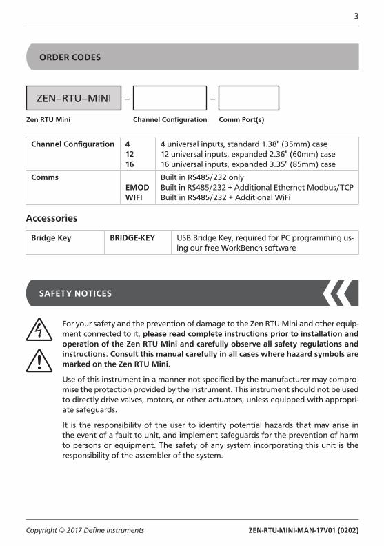
ORDER CODES
Channel Configuration 41216
4 universal inputs, standard 1.38" (35mm) case12 universal inputs, expanded 2.36" (60mm) case16 universal inputs, expanded 3.35" (85mm) case
CommsEMODWIFI
Built in RS485/232 onlyBuilt in RS485/232 + Additional Ethernet Modbus/TCPBuilt in RS485/232 + Additional WiFi
Accessories
Bridge Key BRIDGE-KEY USB Bridge Key, required for PC programming us-ing our free WorkBench software
Zen RTU Mini Channel Configuration
ZEN–RTU–MINI – –
Comm Port(s)
SAFETY NOTICES
For your safety and the prevention of damage to the Zen RTU Mini and other equip-ment connected to it, please read complete instructions prior to installation and operation of the Zen RTU Mini and carefully observe all safety regulations and instructions. Consult this manual carefully in all cases where hazard symbols are marked on the Zen RTU Mini.
Use of this instrument in a manner not specified by the manufacturer may compro-mise the protection provided by the instrument. This instrument should not be used to directly drive valves, motors, or other actuators, unless equipped with appropri-ate safeguards.
It is the responsibility of the user to identify potential hazards that may arise in the event of a fault to unit, and implement safeguards for the prevention of harm to persons or equipment. The safety of any system incorporating this unit is the responsibility of the assembler of the system.
ZEN-RTU-MINI-MAN-17V01 (0202) Copyright © 2017 Define Instruments
4
1 SPECIFICATIONS
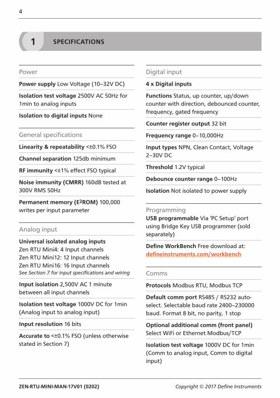
Power
Power supply Low Voltage (10–32V DC)
Isolation test voltage 2500V AC 50Hz for 1min to analog inputs
Isolation to digital inputs None
General specifications
Linearity & repeatability <±0.1% FSO
Channel separation 125db minimum
RF immunity <±1% effect FSO typical
Noise immunity (CMRR) 160dB tested at 300V RMS 50Hz
Permanent memory (E2ROM) 100,000 writes per input parameter
Analog input
Universal isolated analog inputsZen RTU Mini4: 4 Input channelsZen RTU Mini12: 12 Input channelsZen RTU Mini16: 16 Input channelsSee Section 7 for input specifications and wiring
Input isolation 2,500V AC 1 minute between all input channels
Isolation test voltage 1000V DC for 1min(Analog input to analog input)
Input resolution 16 bits
Accurate to <±0.1% FSO (unless otherwise stated in Section 7)
Digital input
4 x Digital inputs
Functions Status, up counter, up/down counter with direction, debounced counter, frequency, gated frequency
Counter register output 32 bit
Frequency range 0–10,000Hz
Input types NPN, Clean Contact, Voltage 2–30V DC
Threshold 1.2V typical
Debounce counter range 0–100Hz
Isolation Not isolated to power supply
ProgrammingUSB programmable Via 'PC Setup' port using Bridge Key USB programmer (sold separately)
Define WorkBench Free download at: defineinstruments.com/workbench
Comms
Protocols Modbus RTU, Modbus TCP
Default comm port RS485 / RS232 auto-select. Selectable baud rate 2400–230000 baud. Format 8 bit, no parity, 1 stop
Optional additional comm (front panel) Select WiFi or Ethernet Modbus/TCP
Isolation test voltage 1000V DC for 1min(Comm to analog input, Comm to digital input)
ZEN-RTU-MINI-MAN-17V01 (0202) Copyright © 2017 Define Instruments
5
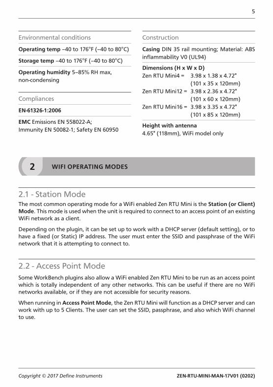
Environmental conditions
Operating temp –40 to 176°F (–40 to 80°C)
Storage temp –40 to 176°F (–40 to 80°C)
Operating humidity 5–85% RH max, non-condensing
Compliances
EN-61326-1:2006
EMC Emissions EN 558022-A;Immunity EN 50082-1; Safety EN 60950
Construction
Casing DIN 35 rail mounting; Material: ABS inflammability V0 (UL94)
Dimensions (H x W x D)Zen RTU Mini4 = 3.98 x 1.38 x 4.72" (101 x 35 x 120mm)Zen RTU Mini12 = 3.98 x 2.36 x 4.72" (101 x 60 x 120mm)Zen RTU Mini16 = 3.98 x 3.35 x 4.72" (101 x 85 x 120mm)
Height with antenna4.65" (118mm), WiFi model only
2 WIFI OPERATING MODES
2.1 - Station ModeThe most common operating mode for a WiFi enabled Zen RTU Mini is the Station (or Client) Mode. This mode is used when the unit is required to connect to an access point of an existing WiFi network as a client.
Depending on the plugin, it can be set up to work with a DHCP server (default setting), or to have a fixed (or Static) IP address. The user must enter the SSID and passphrase of the WiFi network that it is attempting to connect to.
2.2 - Access Point ModeSome WorkBench plugins also allow a WiFi enabled Zen RTU Mini to be run as an access point which is totally independent of any other networks. This can be useful if there are no WiFi networks available, or if they are not accessible for security reasons.
When running in Access Point Mode, the Zen RTU Mini will function as a DHCP server and can work with up to 5 Clients. The user can set the SSID, passphrase, and also which WiFi channel to use.
ZEN-RTU-MINI-MAN-17V01 (0202) Copyright © 2017 Define Instruments
6
3 DIMENSIONS & INSTALLATION
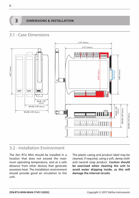
3.1 - Case Dimensions
4.72" (120mm)
5.75" (146mm)
4.65
" (1
18m
m)
3.98
" (10
1mm
)
DIN
35
Rai
l
4.45
" (11
3mm
)
Min
i4: 1
.38"
(35m
m)
Min
i12:
2.3
6" (
60m
m)
Min
i16:
3.3
5" (
85m
m)
Mini4: 1.38"(35mm)
Mini12: 2.36" (60mm)
Mini16: 3.35" (85mm)
3.2 - Installation Environment
The Zen RTU Mini should be installed in a location that does not exceed the maxi-mum operating temperature, and at a safe distance from other devices that generate excessive heat. The installation environment should provide good air circulation to the unit.
The plastic casing and product label may be cleaned, if required, using a soft, damp cloth and neutral soap product. Caution should be exercised when cleaning the unit to avoid water dripping inside, as this will damage the internal circuits.
ZEN-RTU-MINI-MAN-17V01 (0202) Copyright © 2017 Define Instruments
7
3.3 - Installation Instructions
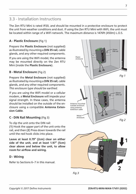
The Zen RTU Mini is rated IP20, and should be mounted in a protective enclosure to protect the unit from weather conditions and dust. If using the Zen RTU Mini with WiFi, the unit must be located within range of a WiFi network. The maximum distance is 1476ft (450m) L.O.S.
A - Plastic Enclosure (Fig 1)
Prepare the Plastic Enclosure (not supplied) as illustrated by mounting a DIN 35 rail, cable glands, and any other required components.
If you are using the WiFi model, the antenna may be mounted directly on the Zen RTU Mini (inside the Plastic Enclosure).
B - Metal Enclosure (Fig 2)
Prepare the Metal Enclosure (not supplied) as illustrated by mounting a DIN 35 rail, cable glands, and any other required components. This enclosure type should be earthed.
If you are using the WiFi model or a cellular modem, a Metal Enclosure will impede your signal strength. In these cases, the antenna should be installed on the outside of the en-closure using a compatible Antenna Exten-sion Cable.
C - DIN Rail Mounting (Fig 3)
To clip the unit onto the DIN rail:(1) Hook the upper part of the unit onto the rail, and then (2) Press down towards the rail until the red hook clicks into place.
Leave at least 0.79" (2cm) clear on either side of the unit, and at least 1.97" (5cm) clear above and below the unit, to allow room for airflow and wiring.
D - Wiring
Refer to Sections 6–7 in this manual.
Fig 1
35mmDIN rail
Plasticenclosure
35mmDIN rail
Metalenclosure
Antenna mountedoutside enclosureusing antennaextension cable
Fig 2
Fig 3

ZEN-RTU-MINI-MAN-17V01 (0202) Copyright © 2017 Define Instruments
8
3.4 - EMC Installation Guidelines
The Zen RTU Mini has been designed to cope with large EMC disturbances. This has been achieved by continual testing and improvement of filtering and layout techniques.
The Zen RTU Mini meets CE noise require-ments, and even surpasses them in many tests. (For full details and test results, see Appendix A.) However in some applications with less than optimum installations and large power switching, the EMC perfor-mance of the unit can be further improved by:
A Installing the unit in an earthed Metal Enclosure (as in Fig 2). This is particular-ly useful if the control box is mounted close to large power switching devices like contactors. Every switching cycle there is a possibility of generating a large amount of near field radiated noise. The Metal Enclosure, acting as a faraday cage, will shunt this radiation to ground and away from the unit.
B Increasing the physical distance from the power devices. For example, in-creasing the control box distance from 6" to 12" from the noise source will re-duce the noise seen by the control box by a factor of 4. (Probably the cheapest and best results in this situation could
be obtained by adding RC snubbers to the contactors or power switches.)
C Using shielded cable on sensitive input and control signal lines. Good results can be obtained by grounding the shields to the metal enclosure close to the entry point. All cables act as aeri-als and pick up unwanted R.F. radiated signals and noise; the earthed shield acts as a faraday cage around the ca-bles, shunting the unwanted energy to ground.
Shields can also help with capacitively coupled noise typically found in circum-stances when signal cable is laid on top of noisy switching power cables. Of course in this case you are better off to keep separate signal and power lines.
D Laying cable on earthed cable trays can also help reduce noise seen by the Zen RTU Mini. This is particularly useful if there are long cable runs, or the unit is close to radiating sources such as two way radios.
E - Removal from DIN Rail (Fig 4)
To unclip the unit from the DIN rail, power the unit down and remove the power connector.
Then insert a small screwdriver into the slot on the red hook (just visible when the power connector is removed), and lever it down. This will release the hook, allowing the unit to be detached from the DIN rail.
Fig 4
ZEN-RTU-MINI-MAN-17V01 (0202) Copyright © 2017 Define Instruments
9
4 INSTALLING DEFINE WORKBENCH
Define WorkBench offers a comprehensive and yet simple-to-use setup tool for your Zen RTU Mini, complete with data log extraction and visualization.
You must install WorkBench before connecting the Zen RTU Mini to your computer. If you have already connected using the Bridge Key, please disconnect before continuing.
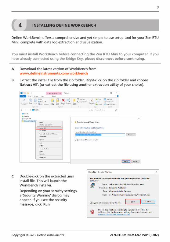
A Download the latest version of WorkBench fromwww.defineinstruments.com/workbench
B Extract the install file from the zip folder. Right-click on the zip folder and choose 'Extract All', (or extract the file using another extraction utility of your choice).
C Double-click on the extracted .msi install file. This will launch the WorkBench installer.
Depending on your security settings, a 'Security Warning' dialog may appear. If you see the security message, click 'Run'.
ZEN-RTU-MINI-MAN-17V01 (0202) Copyright © 2017 Define Instruments
10
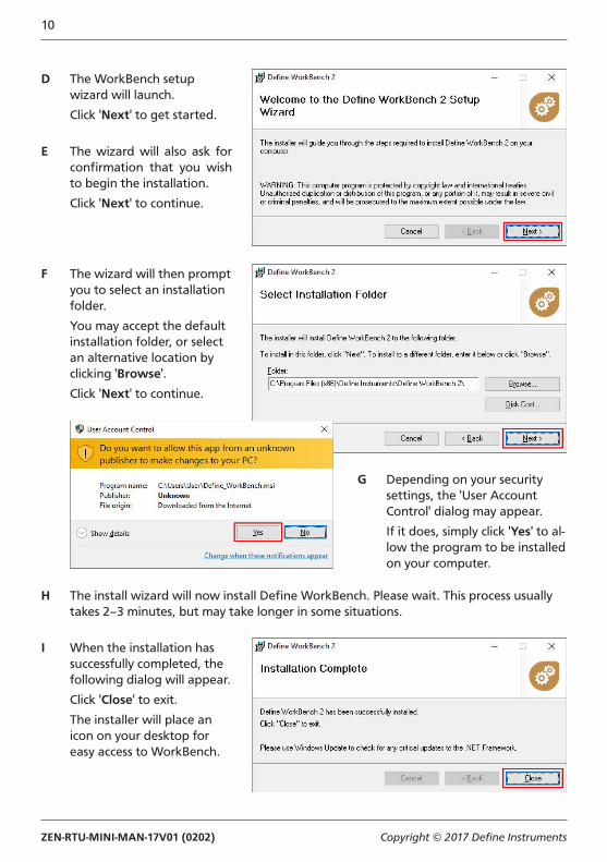
D The WorkBench setup wizard will launch.
Click 'Next' to get started.
E The wizard will also ask for confirmation that you wish to begin the installation.
Click 'Next' to continue.
F The wizard will then prompt you to select an installation folder.
You may accept the default installation folder, or select an alternative location by clicking 'Browse'.
Click 'Next' to continue.
G Depending on your security settings, the 'User Account Control' dialog may appear.
If it does, simply click 'Yes' to al-low the program to be installed on your computer.
H The install wizard will now install Define WorkBench. Please wait. This process usually takes 2–3 minutes, but may take longer in some situations.
I When the installation has successfully completed, the following dialog will appear.
Click 'Close' to exit.
The installer will place an icon on your desktop for easy access to WorkBench.

ZEN-RTU-MINI-MAN-17V01 (0202) Copyright © 2017 Define Instruments
11
5 SOFTWARE CONFIGURATION
5.1 - Connecting
Connect the Bridge Key
To program your Zen RTU Mini, connect one end of the Interface Cable to the 'PC Setup' port on the unit's front panel, and the other end to your Bridge Key.
Then plug the Bridge Key into your com-puter's USB port (see Fig 5).
Supply Power
Supply power to the Zen RTU Mini, referring to 6.1 for wiring.
Connect to your Zen RTU Mini in Define WorkBench
Launch Define WorkBench (see Section 4 for installation instructions), and select the 'Prog Port' tab.
If your Zen RTU Mini is powered up and con-nected via the Bridge Key, then the COM Port will be detected automatically. Click 'Connect'.
Fig 5
ZEN-RTU-MINI-MAN-17V01 (0202) Copyright © 2017 Define Instruments
12
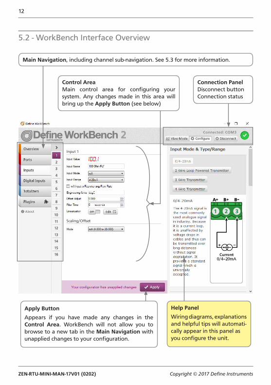
Main Navigation, including channel sub-navigation. See 5.3 for more information.
Control AreaMain control area for configuring your system. Any changes made in this area will bring up the Apply Button (see below)
Connection PanelDisconnect buttonConnection status
Apply Button
Appears if you have made any changes in the Control Area. WorkBench will not allow you to browse to a new tab in the Main Navigation with unapplied changes to your configuration.
Help Panel
Wiring diagrams, explanationsand helpful tips will automati-cally appear in this panel as you configure the unit.
5.2 - WorkBench Interface Overview
ZEN-RTU-MINI-MAN-17V01 (0202) Copyright © 2017 Define Instruments
13
5.3 - Main Navigation
OverviewView basic device information including Se-rial Number and firmware version. Password protect, export a configuration certificate, and save/upload configuration settings.
PortsThis tab is only visible if you are connected to your Zen RTU Mini via the USB Programming Port. It enables you to configure a range of settings for the default RS232 / RS485 port.
InputsSet up and scale the universal isolated input channels. Includes integrated wiring dia-grams and examples.
Digital InputsSet up the four digital inputs and view their live status.
TotalizersConfigure up to 10 totalizers using either an input channel or a digital input as the source.
PluginsPlugins are small programs which are loaded into the Zen RTU Mini to expand its func-tionality or simplify its use. Available plugins include:
Ĝ WiFi (requires WiFi hardware)Enables your Zen RTU Mini to wirelessly connect to a LAN or the internet via a local WiFi network, allowing it to become a Modbus TCP server for configuration or data viewing applications.
Ĝ Ethernet (requires Ethernet hardware)This plugin enables your Zen RTU Mini to connect to a LAN or the internet via wired Ethernet connection, allowing it to become a Modbus TCP server for configuration or data viewing applications.
ZEN-RTU-MINI-MAN-17V01 (0202) Copyright © 2017 Define Instruments
14
6 WIRING & LED'S
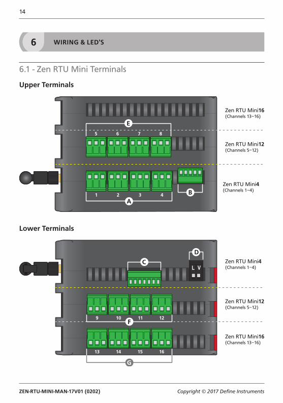
6.1 - Zen RTU Mini Terminals
Upper Terminals
Zen RTU Mini4(Channels 1−4)
Zen RTU Mini12(Channels 5−12)
Zen RTU Mini16(Channels 13−16)
Lower Terminals
Zen RTU Mini4(Channels 1−4)
Zen RTU Mini12(Channels 5−12)
Zen RTU Mini16(Channels 13−16)
ZEN-RTU-MINI-MAN-17V01 (0202) Copyright © 2017 Define Instruments
15
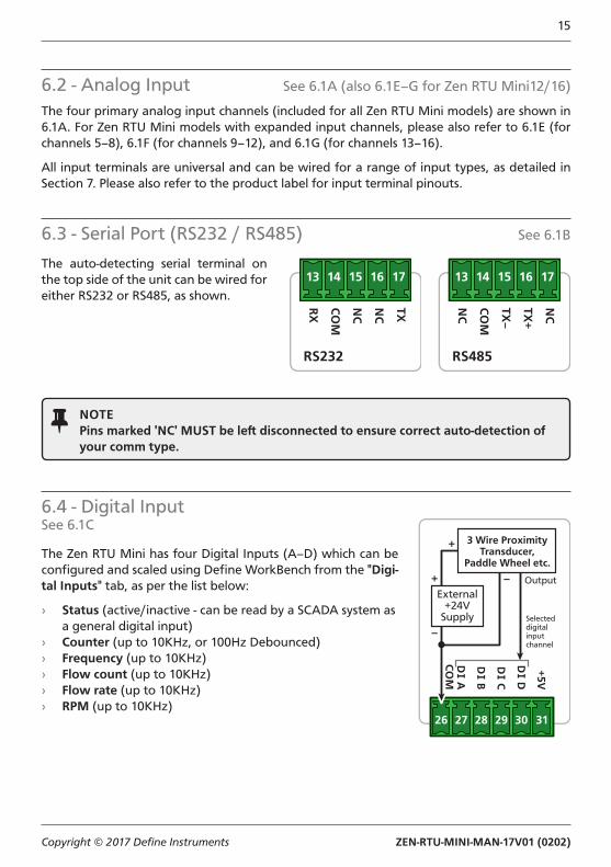
6.2 - Analog Input See 6.1A (also 6.1E–G for Zen RTU Mini12/16)
The four primary analog input channels (included for all Zen RTU Mini models) are shown in 6.1A. For Zen RTU Mini models with expanded input channels, please also refer to 6.1E (for channels 5–8), 6.1F (for channels 9–12), and 6.1G (for channels 13–16).
All input terminals are universal and can be wired for a range of input types, as detailed in Section 7. Please also refer to the product label for input terminal pinouts.
6.3 - Serial Port (RS232 / RS485) See 6.1B
The auto-detecting serial terminal on the top side of the unit can be wired for either RS232 or RS485, as shown.
TXNC
NC
CO
M
RX
RS232
NC
TX+
TX–
CO
M
NC
RS485
NOTEPins marked 'NC' MUST be left disconnected to ensure correct auto-detection of your comm type.
6.4 - Digital InputSee 6.1C
The Zen RTU Mini has four Digital Inputs (A–D) which can be configured and scaled using Define WorkBench from the "Digi-tal Inputs" tab, as per the list below:
› Status (active/inactive - can be read by a SCADA system as a general digital input)
› Counter (up to 10KHz, or 100Hz Debounced) › Frequency (up to 10KHz) › Flow count (up to 10KHz) › Flow rate (up to 10KHz) › RPM (up to 10KHz)
External+24V
Supply
3 Wire ProximityTransducer,
Paddle Wheel etc.
Output
Selecteddigitalinputchannel
+5V
D D
D C
D B
D A
CO
M
ZEN-RTU-MINI-MAN-17V01 (0202) Copyright © 2017 Define Instruments
16
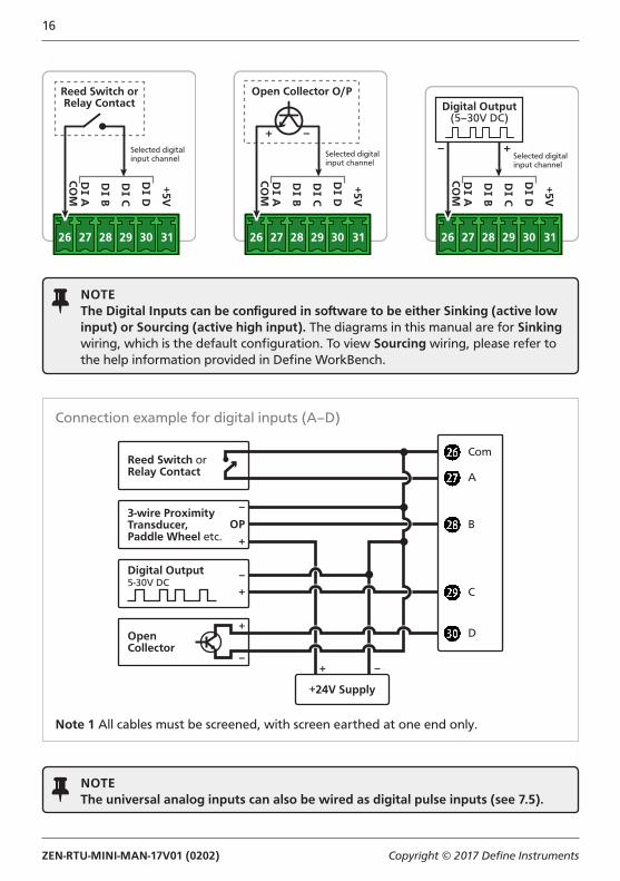
NOTEThe Digital Inputs can be configured in software to be either Sinking (active low input) or Sourcing (active high input). The diagrams in this manual are for Sinking wiring, which is the default configuration. To view Sourcing wiring, please refer to the help information provided in Define WorkBench.
Connection example for digital inputs (A–D)
Reed Switch orRelay Contact
3-wire ProximityTransducer,Paddle Wheel etc.
+24V Supply
Com
A
B
D
C
–
OP
+
–
+
Digital Output5-30V DC
OpenCollector
+
–+ –
Note 1 All cables must be screened, with screen earthed at one end only.
NOTEThe universal analog inputs can also be wired as digital pulse inputs (see 7.5).
Reed Switch orRelay Contact
Selected digitalinput channel
+5V
D D
D C
D B
D A
CO
M
Open Collector O/P
Selected digitalinput channel
+5V
D D
D C
D B
D A
CO
M
Digital Output(5–30V DC)
Selected digitalinput channel
+5V
D D
D C
D B
D A
CO
M

ZEN-RTU-MINI-MAN-17V01 (0202) Copyright © 2017 Define Instruments
17
6.5 - Power SupplySee 6.1D
Wire your power supply for 10–32V DC supply, as shown.
(If the supply voltage is less than 10V at power up, the power LED (see 6.6B) will flash very quickly every 2–3 seconds until the supply voltage reaches an acceptable level.)
CAUTIONLow voltage (10–32V DC) only. Higher voltages will damage the Zen RTU Mini.
10–32V DC
6.6 - Front Panel & LED's
B - Additional comm port and LED status area
EMOD WIFI
LED Description
Flashing between Green & Red= Normal operation.Red for 2–3 seconds following power up= Unit is booting up and checking for errors.Intermittent rapid flashing Red= Supply voltage is too low.Red continually= Error (contact your distributor).
Flashing= Data is being transmitted, or a connection is being established.
Link LED's indicate the status of the wireless link.
Green Off, Red On= Not connected (idle).Green/Red Toggling= Trying to connect in Station Mode.Green/Red Flashing= Trying to connect in Access Point Mode.Green On, Red Off= Station Connected.Green On, Red On= Access Point Connected.Note: See Section 2 for more information on WiFi operating modes.
A - Programming portSee 5.1
ZEN-RTU-MINI-MAN-17V01 (0202) Copyright © 2017 Define Instruments
18
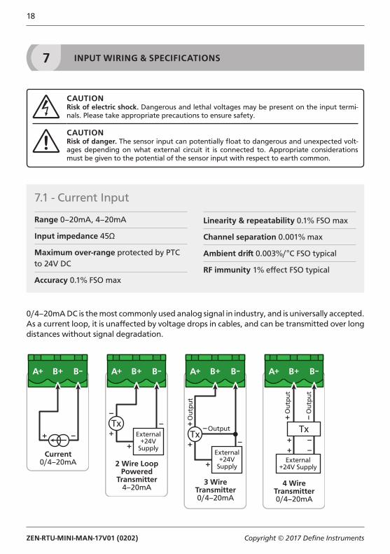
7 INPUT WIRING & SPECIFICATIONS
CAUTIONRisk of electric shock. Dangerous and lethal voltages may be present on the input termi-nals. Please take appropriate precautions to ensure safety.
CAUTIONRisk of danger. The sensor input can potentially float to dangerous and unexpected volt-ages depending on what external circuit it is connected to. Appropriate considerations must be given to the potential of the sensor input with respect to earth common.
7.1 - Current Input
Range 0–20mA, 4–20mA
Input impedance 45Ω
Maximum over-range protected by PTC to 24V DC
Accuracy 0.1% FSO max
Linearity & repeatability 0.1% FSO max
Channel separation 0.001% max
Ambient drift 0.003%/°C FSO typical
RF immunity 1% effect FSO typical
0/4–20mA DC is the most commonly used analog signal in industry, and is universally accepted. As a current loop, it is unaffected by voltage drops in cables, and can be transmitted over long distances without signal degradation.
Current0/4–20mA 2 Wire Loop
PoweredTransmitter
4–20mA
External+24V
Supply
3 WireTransmitter0/4–20mA
Out
put
Output
External+24V
Supply
4 WireTransmitter0/4–20mA
Out
put
Out
put
External+24V Supply
ZEN-RTU-MINI-MAN-17V01 (0202) Copyright © 2017 Define Instruments
19
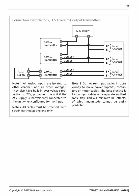
Connection example for 2, 3 & 4 wire mA output transmitters
PowerSupply
2-WireTransmitter
3-WireTransmitter
4-WireTransmitter
+24V Supply
InputChannel
InputChannel
InputChannel
Output +
Output −
Output +
Output −
B+B–
B+B–
B+B–
Note 1 All analog inputs are isolated to other channels and all other voltages. They also have built in over voltage pro-tection to 24V, protecting the unit if the 24V supply is inadvertently connected to the unit when configured for mA input.
Note 2 All cables must be screened, with screen earthed at one end only.
Note 3 Do not run input cables in close vicinity to noisy power supplies, contac-tors or motor cables. The best practice is to run input cables on a separate earthed cable tray. This will minimize RFI effects, of which magnitude cannot be easily predicted.
ZEN-RTU-MINI-MAN-17V01 (0202) Copyright © 2017 Define Instruments
20
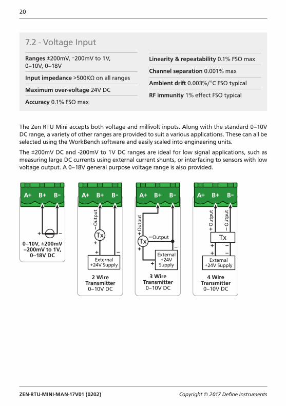
The Zen RTU Mini accepts both voltage and millivolt inputs. Along with the standard 0–10V DC range, a variety of other ranges are provided to suit a various applications. These can all be selected using the WorkBench software and easily scaled into engineering units.
The ±200mV DC and -200mV to 1V DC ranges are ideal for low signal applications, such as measuring large DC currents using external current shunts, or interfacing to sensors with low voltage output. A 0–18V general purpose voltage range is also provided.
0–10V, ±200mV–200mV to 1V,
0–18V DC
3 WireTransmitter0–10V DC
Out
put
Output
External+24V
Supply
4 WireTransmitter0–10V DC
Out
put
Out
put
External+24V Supply
2 WireTransmitter0–10V DC
Out
put
External+24V Supply
7.2 - Voltage Input
Ranges ±200mV, –200mV to 1V,0–10V, 0–18V
Input impedance >500KΩ on all ranges
Maximum over-voltage 24V DC
Accuracy 0.1% FSO max
Linearity & repeatability 0.1% FSO max
Channel separation 0.001% max
Ambient drift 0.003%/°C FSO typical
RF immunity 1% effect FSO typical
ZEN-RTU-MINI-MAN-17V01 (0202) Copyright © 2017 Define Instruments
21
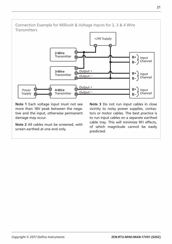
Connection Example for Millivolt & Voltage Inputs for 2, 3 & 4 Wire Transmitters
PowerSupply
2-WireTransmitter
3-WireTransmitter
4-WireTransmitter
+24V Supply
InputChannel
InputChannel
InputChannel
Output +
Output −
Output +
Output −
B+B–
B+B–
B+B–
Note 1 Each voltage input must not see more than 18V peak between the nega-tive and the input, otherwise permanent damage may occur.
Note 2 All cables must be screened, with screen earthed at one end only.
Note 3 Do not run input cables in close vicinity to noisy power supplies, contac-tors or motor cables. The best practice is to run input cables on a separate earthed cable tray. This will minimize RFI effects, of which magnitude cannot be easily predicted.
ZEN-RTU-MINI-MAN-17V01 (0202) Copyright © 2017 Define Instruments
22
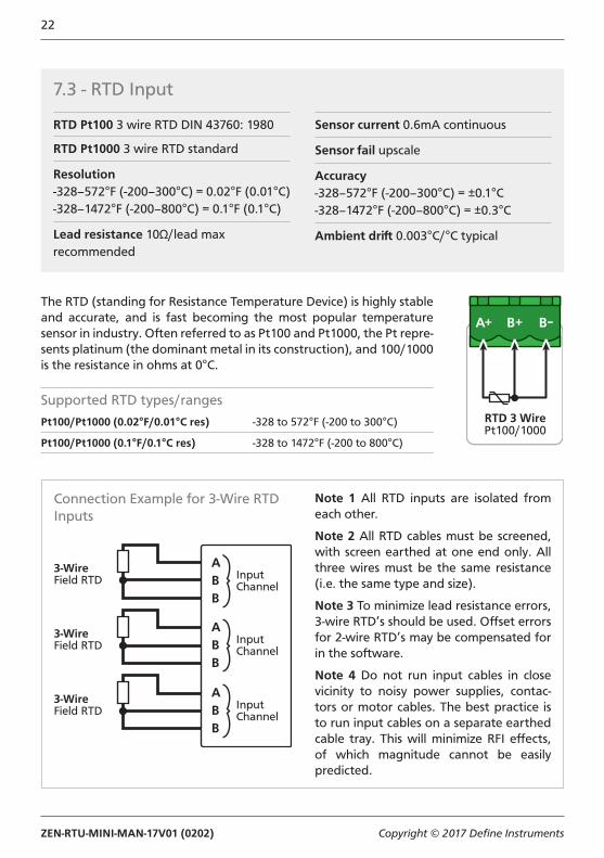
The RTD (standing for Resistance Temperature Device) is highly stable and accurate, and is fast becoming the most popular temperature sensor in industry. Often referred to as Pt100 and Pt1000, the Pt repre-sents platinum (the dominant metal in its construction), and 100/1000 is the resistance in ohms at 0°C.
Supported RTD types/ranges
Pt100/Pt1000 (0.02°F/0.01°C res) -328 to 572°F (-200 to 300°C)
Pt100/Pt1000 (0.1°F/0.1°C res) -328 to 1472°F (-200 to 800°C)
RTD 3 WirePt100/1000
Connection Example for 3-Wire RTD Inputs
3-WireField RTD Input
Channel
ABB
3-WireField RTD Input
Channel
ABB
3-WireField RTD Input
Channel
ABB
Note 1 All RTD inputs are isolated from each other.
Note 2 All RTD cables must be screened, with screen earthed at one end only. All three wires must be the same resistance (i.e. the same type and size).
Note 3 To minimize lead resistance errors, 3-wire RTD’s should be used. Offset errors for 2-wire RTD’s may be compensated for in the software.
Note 4 Do not run input cables in close vicinity to noisy power supplies, contac-tors or motor cables. The best practice is to run input cables on a separate earthed cable tray. This will minimize RFI effects, of which magnitude cannot be easily predicted.
7.3 - RTD Input
RTD Pt100 3 wire RTD DIN 43760: 1980
RTD Pt1000 3 wire RTD standard
Resolution-328–572°F (-200–300°C) = 0.02°F (0.01°C)-328–1472°F (-200–800°C) = 0.1°F (0.1°C)
Lead resistance 10Ω/lead max recommended
Sensor current 0.6mA continuous
Sensor fail upscale
Accuracy-328–572°F (-200–300°C) = ±0.1°C-328–1472°F (-200–800°C) = ±0.3°C
Ambient drift 0.003°C/°C typical
ZEN-RTU-MINI-MAN-17V01 (0202) Copyright © 2017 Define Instruments
23
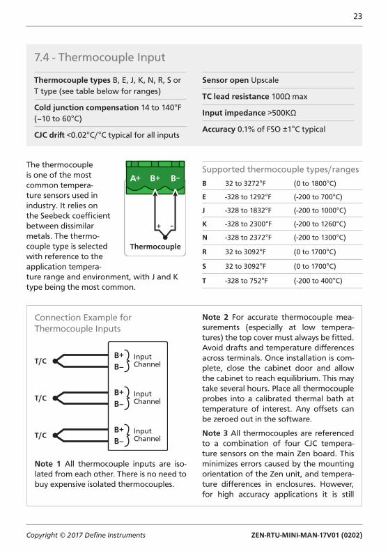
7.4 - Thermocouple Input
Thermocouple types B, E, J, K, N, R, S or T type (see table below for ranges)
Cold junction compensation 14 to 140°F (–10 to 60°C)
CJC drift <0.02°C/°C typical for all inputs
Sensor open Upscale
TC lead resistance 100Ω max
Input impedance >500KΩ
Accuracy 0.1% of FSO ±1°C typical
The thermocouple is one of the most common tempera-ture sensors used in industry. It relies on the Seebeck coefficient between dissimilar metals. The thermo-couple type is selected with reference to the application tempera-ture range and environment, with J and K type being the most common.
Supported thermocouple types/ranges
B 32 to 3272°F (0 to 1800°C)
E -328 to 1292°F (-200 to 700°C)
J -328 to 1832°F (-200 to 1000°C)
K -328 to 2300°F (-200 to 1260°C)
N -328 to 2372°F (-200 to 1300°C)
R 32 to 3092°F (0 to 1700°C)
S 32 to 3092°F (0 to 1700°C)
T -328 to 752°F (-200 to 400°C)
Thermocouple
Connection Example for Thermocouple Inputs
T/C
T/C
T/C
InputChannel
B+B–
InputChannel
B+B–
InputChannel
B+B–
Note 1 All thermocouple inputs are iso-lated from each other. There is no need to buy expensive isolated thermocouples.
Note 2 For accurate thermocouple mea-surements (especially at low tempera-tures) the top cover must always be fitted. Avoid drafts and temperature differences across terminals. Once installation is com-plete, close the cabinet door and allow the cabinet to reach equilibrium. This may take several hours. Place all thermocouple probes into a calibrated thermal bath at temperature of interest. Any offsets can be zeroed out in the software.
Note 3 All thermocouples are referenced to a combination of four CJC tempera-ture sensors on the main Zen board. This minimizes errors caused by the mounting orientation of the Zen unit, and tempera-ture differences in enclosures. However, for high accuracy applications it is still
ZEN-RTU-MINI-MAN-17V01 (0202) Copyright © 2017 Define Instruments
24
recommended to zero errors (see Note 2).
Note 4 All cables must be screened, with screen earthed at one end only.
Note 5 When thermocouple inputs are se-lected, an upscale resistor is automatically connected to the T/C + input, resulting in an overflow condition for open or broken sensors.
Note 4 Do not run input cables in close vicinity to noisy power supplies, contac-tors or motor cables. The best practice is to run input cables on a separate earthed cable tray. This will minimize RFI effects, of which magnitude cannot be easily predicted.
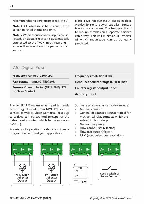
The Zen RTU Mini's universal input terminals accept digital inputs from NPN, PNP or TTL sensors as well as Clean Contacts. Pulses up to 2.5kHz can be counted (except for the debounced counter, which has a range of 0–50Hz).
A variety of operating modes are software programmable to suit your application.
Software programmable modes include: › General counter › General debounced counter (ideal for
mechanical relay contacts which are subject to bouncing)
› General frequency › Flow count (uses K-factor) › Flow rate (uses K-factor) › RPM (uses pulses per revolution)
7.5 - Digital Pulse
Frequency range 0–2500.0Hz
Fast counter range 0–2500.0Hz
Sensors Open collector (NPN, PNP), TTL or Clean Contact
Frequency resolution 0.1Hz
Debounce counter range 0–50Hz max
Counter register output 32 bit
Accuracy ±0.5%
NPN OpenCollectorOutput
PNP OpenCollectorOutput TTL Input
Reed Switch orRelay Contact
ZEN-RTU-MINI-MAN-17V01 (0202) Copyright © 2017 Define Instruments
25
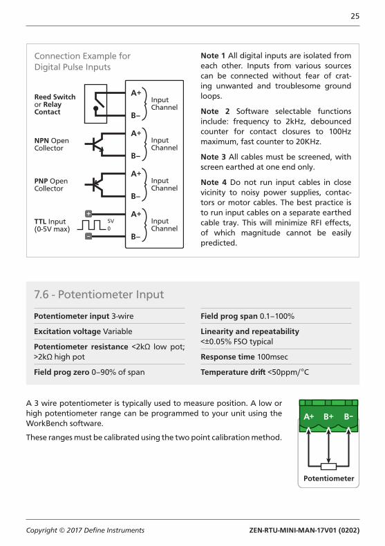
Connection Example for Digital Pulse Inputs
NPN OpenCollector
Reed Switchor RelayContact
PNP OpenCollector
TTL Input(0-5V max)
5V0
InputChannel
A+
B–
InputChannel
A+
B–
InputChannel
A+
B–
InputChannel
A+
B–
Note 1 All digital inputs are isolated from each other. Inputs from various sources can be connected without fear of crat-ing unwanted and troublesome ground loops.
Note 2 Software selectable functions include: frequency to 2kHz, debounced counter for contact closures to 100Hz maximum, fast counter to 20KHz.
Note 3 All cables must be screened, with screen earthed at one end only.
Note 4 Do not run input cables in close vicinity to noisy power supplies, contac-tors or motor cables. The best practice is to run input cables on a separate earthed cable tray. This will minimize RFI effects, of which magnitude cannot be easily predicted.
7.6 - Potentiometer Input
Potentiometer input 3-wire
Excitation voltage Variable
Potentiometer resistance <2kΩ low pot; >2kΩ high pot
Field prog zero 0–90% of span
Field prog span 0.1–100%
Linearity and repeatability<±0.05% FSO typical
Response time 100msec
Temperature drift <50ppm/°C
A 3 wire potentiometer is typically used to measure position. A low or high potentiometer range can be programmed to your unit using the WorkBench software.
These ranges must be calibrated using the two point calibration method.
Potentiometer
ZEN-RTU-MINI-MAN-17V01 (0202) Copyright © 2017 Define Instruments
26
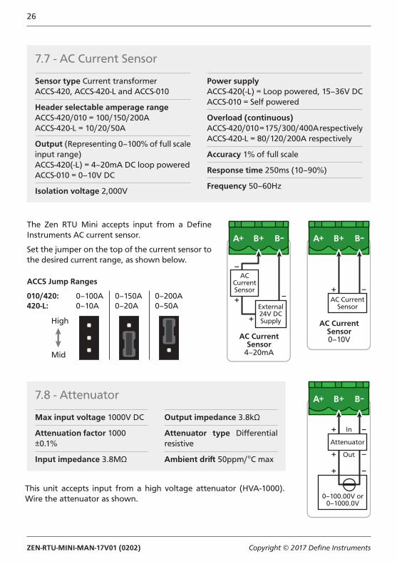
7.7 - AC Current Sensor
Sensor type Current transformerACCS-420, ACCS-420-L and ACCS-010
Header selectable amperage rangeACCS-420/010 = 100/150/200AACCS-420-L = 10/20/50A
Output (Representing 0–100% of full scale input range)ACCS-420(-L) = 4–20mA DC loop poweredACCS-010 = 0–10V DC
Isolation voltage 2,000V
Power supplyACCS-420(-L) = Loop powered, 15–36V DCACCS-010 = Self powered
Overload (continuous)ACCS-420/010 = 175/300/400A respectivelyACCS-420-L = 80/120/200A respectively
Accuracy 1% of full scale
Response time 250ms (10–90%)
Frequency 50–60Hz
The Zen RTU Mini accepts input from a Define Instruments AC current sensor.
Set the jumper on the top of the current sensor to the desired current range, as shown below.
ACCS Jump Ranges
0–100A0–10A
0–150A0–20A
0–200A0–50A
010/420:420-L:
AC CurrentSensor
4–20mA
External24V DCSupply
ACCurrentSensor
AC CurrentSensor0–10V
AC CurrentSensor
This unit accepts input from a high voltage attenuator (HVA-1000). Wire the attenuator as shown.
7.8 - Attenuator
Max input voltage 1000V DC
Attenuation factor 1000 ±0.1%
Input impedance 3.8MΩ
Output impedance 3.8kΩ
Attenuator type Differential resistive
Ambient drift 50ppm/°C max
Attenuator
0–100.00V or0–1000.0V
In
Out
ZEN-RTU-MINI-MAN-17V01 (0202) Copyright © 2017 Define Instruments
27
8 CONNECTING TO A PLC
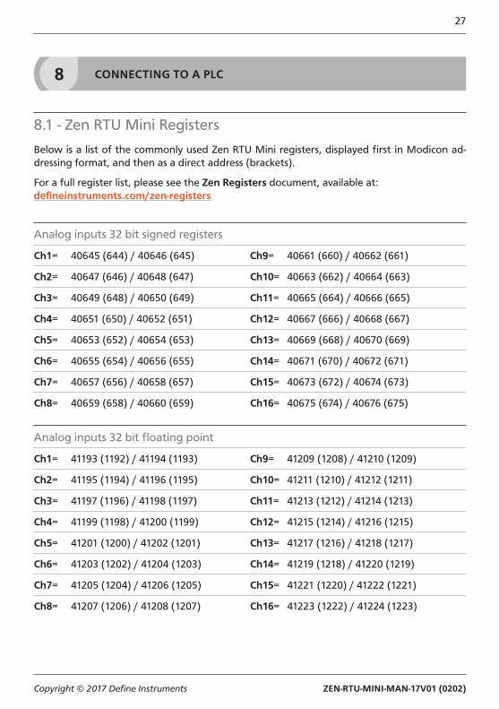
8.1 - Zen RTU Mini Registers
Below is a list of the commonly used Zen RTU Mini registers, displayed first in Modicon ad-dressing format, and then as a direct address (brackets).
For a full register list, please see the Zen Registers document, available at:defineinstruments.com/zen-registers
Analog inputs 32 bit signed registers
Ch1= 40645 (644) / 40646 (645) Ch9= 40661 (660) / 40662 (661)
Ch2= 40647 (646) / 40648 (647) Ch10= 40663 (662) / 40664 (663)
Ch3= 40649 (648) / 40650 (649) Ch11= 40665 (664) / 40666 (665)
Ch4= 40651 (650) / 40652 (651) Ch12= 40667 (666) / 40668 (667)
Ch5= 40653 (652) / 40654 (653) Ch13= 40669 (668) / 40670 (669)
Ch6= 40655 (654) / 40656 (655) Ch14= 40671 (670) / 40672 (671)
Ch7= 40657 (656) / 40658 (657) Ch15= 40673 (672) / 40674 (673)
Ch8= 40659 (658) / 40660 (659) Ch16= 40675 (674) / 40676 (675)
Analog inputs 32 bit floating point
Ch1= 41193 (1192) / 41194 (1193) Ch9= 41209 (1208) / 41210 (1209)
Ch2= 41195 (1194) / 41196 (1195) Ch10= 41211 (1210) / 41212 (1211)
Ch3= 41197 (1196) / 41198 (1197) Ch11= 41213 (1212) / 41214 (1213)
Ch4= 41199 (1198) / 41200 (1199) Ch12= 41215 (1214) / 41216 (1215)
Ch5= 41201 (1200) / 41202 (1201) Ch13= 41217 (1216) / 41218 (1217)
Ch6= 41203 (1202) / 41204 (1203) Ch14= 41219 (1218) / 41220 (1219)
Ch7= 41205 (1204) / 41206 (1205) Ch15= 41221 (1220) / 41222 (1221)
Ch8= 41207 (1206) / 41208 (1207) Ch16= 41223 (1222) / 41224 (1223)
ZEN-RTU-MINI-MAN-17V01 (0202) Copyright © 2017 Define Instruments
28
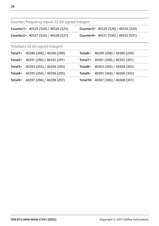
Counter/frequency inputs 32 bit signed integers
Counter1= 40525 (524) / 40526 (525) Counter3= 40529 (528) / 40530 (529)
Counter2= 40527 (526) / 40528 (527) Counter4= 40531 (530) / 40532 (531)
Totalizers 32 bit signed integers
Total1= 40289 (288) / 40290 (289) Total6= 40299 (298) / 40300 (299)
Total2= 40291 (290) / 40292 (291) Total7= 40301 (300) / 40302 (301)
Total3= 40293 (292) / 40294 (293) Total8= 40303 (302) / 40304 (303)
Total4= 40295 (294) / 40296 (295) Total9= 40305 (304) / 40306 (305)
Total5= 40297 (296) / 40298 (297) Total10= 40307 (306) / 40308 (307)
ZEN-RTU-MINI-MAN-17V01 (0202) Copyright © 2017 Define Instruments
29
9 MAINTENANCE
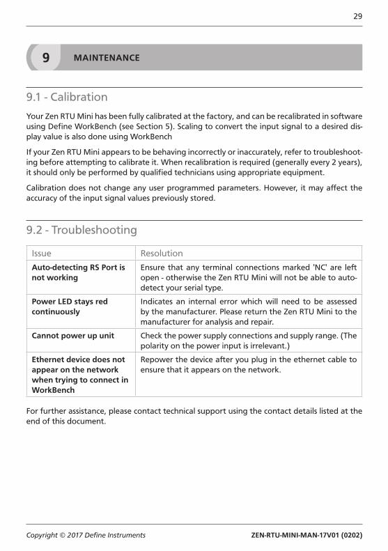
9.1 - Calibration
Your Zen RTU Mini has been fully calibrated at the factory, and can be recalibrated in software using Define WorkBench (see Section 5). Scaling to convert the input signal to a desired dis-play value is also done using WorkBench
If your Zen RTU Mini appears to be behaving incorrectly or inaccurately, refer to troubleshoot-ing before attempting to calibrate it. When recalibration is required (generally every 2 years), it should only be performed by qualified technicians using appropriate equipment.
Calibration does not change any user programmed parameters. However, it may affect the accuracy of the input signal values previously stored.
9.2 - Troubleshooting
Issue Resolution
Auto-detecting RS Port is not working
Ensure that any terminal connections marked 'NC' are left open - otherwise the Zen RTU Mini will not be able to auto-detect your serial type.
Power LED stays red continuously
Indicates an internal error which will need to be assessed by the manufacturer. Please return the Zen RTU Mini to the manufacturer for analysis and repair.
Cannot power up unit Check the power supply connections and supply range. (The polarity on the power input is irrelevant.)
Ethernet device does not appear on the network when trying to connect in WorkBench
Repower the device after you plug in the ethernet cable to ensure that it appears on the network.
For further assistance, please contact technical support using the contact details listed at the end of this document.
ZEN-RTU-MINI-MAN-17V01 (0202) Copyright © 2017 Define Instruments
30
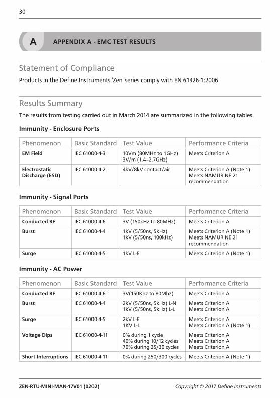
A APPENDIX A - EMC TEST RESULTS
Statement of ComplianceProducts in the Define Instruments 'Zen' series comply with EN 61326-1:2006.
Results SummaryThe results from testing carried out in March 2014 are summarized in the following tables.
Immunity - Enclosure Ports
Phenomenon Basic Standard Test Value Performance Criteria
EM Field IEC 61000-4-3 10Vm (80MHz to 1GHz)3V/m (1.4–2.7GHz)
Meets Criterion A
Electrostatic Discharge (ESD)
IEC 61000-4-2 4kV/8kV contact/air Meets Criterion A (Note 1)Meets NAMUR NE 21 recommendation
Immunity - Signal Ports
Phenomenon Basic Standard Test Value Performance Criteria
Conducted RF IEC 61000-4-6 3V (150kHz to 80MHz) Meets Criterion A
Burst IEC 61000-4-4 1kV (5/50ns, 5kHz) 1kV (5/50ns, 100kHz)
Meets Criterion A (Note 1) Meets NAMUR NE 21 recommendation
Surge IEC 61000-4-5 1kV L-E Meets Criterion A (Note 1)
Immunity - AC Power
Phenomenon Basic Standard Test Value Performance Criteria
Conducted RF IEC 61000-4-6 3V(150Khz to 80Mhz) Meets Criterion A
Burst IEC 61000-4-4 2kV (5/50ns, 5kHz) L-N 1kV (5/50ns, 5kHz) L-L
Meets Criterion A Meets Criterion A
Surge IEC 61000-4-5 2kV L-E1KV L-L
Meets Criterion A Meets Criterion A (Note 1)
Voltage Dips IEC 61000-4-11 0% during 1 cycle 40% during 10/12 cycles 70% during 25/30 cycles
Meets Criterion A Meets Criterion A Meets Criterion A
Short Interruptions IEC 61000-4-11 0% during 250/300 cycles Meets Criterion A (Note 1)
ZEN-RTU-MINI-MAN-17V01 (0202) Copyright © 2017 Define Instruments
31
Performance Criteria
Performance Criterion ADuring the test, normal performance within the specification limits.
Performance Criterion BDuring testing, temporary degradation, or loss of performance or function which is self-recovering.
Performance Criterion CDuring testing, temporary degradation, or loss of function or performance which requires operator intervention or system reset occurs.
*Note 1: EN61326-1 calls for a Criterion B pass; unit exceeds this by meeting Criterion A.

Defi ne Instruments
New Zealand (Head Offi ce)
10B Vega Place, Rosedale, Auckland 0632, New Zealand
PO Box 245 Westpark Village, Auckland 0661, New Zealand
Ph: +64 (9) 835 1550Fax: +64 (9) 835 1250
sales@defi neinstruments.co.nz
www.defi neinstruments.co.nz
United States (Dallas, TX)
Ph: (214) 926 4950
sales@defi neinstruments.com
www.defi neinstruments.com
South Africa (Pretoria)
sales@defi neinstruments.co.za
www.defi neinstruments.co.za
Zen RTU Mini Document Revision Code: ZEN-RTU-MINI-MAN-17V01 Date Code: 170202