Embed Size (px)
Citation preview

ZED-F9Pu-blox F9 high precision GNSS module
Integration manual
AbstractThis document describes the features and application of the ZED-F9P, amulti-band GNSS module with integrated RTK offering centimeter levelaccuracy.
www.u-blox.com
UBX-18010802 - R07

ZED-F9P - Integration manual
Document informationTitle ZED-F9P
Subtitle u-blox F9 high precision GNSS module
Document type Integration manual
Document number UBX-18010802
Revision and date R07 25-Feb-2020
Document status Early production information
This document applies to the following products:
Product name Type number Firmware version PCN reference
ZED-F9P ZED-F9P-01B-01 HPG 1.12 UBX-19057484
u-blox reserves all rights to this document and the information contained herein. Products, names, logos and designsdescribed herein may in whole or in part be subject to intellectual property rights. Reproduction, use, modification ordisclosure to third parties of this document or any part thereof without the express permission of u-blox is strictly prohibited.
The information contained herein is provided "as is" and u-blox assumes no liability for the use of the information. No warranty,either express or implied, is given with respect to, including but not limited to, the accuracy, correctness, reliability and fitnessfor a particular purpose of the information. This document may be revised by u-blox at any time. For most recent documents,please visit www.u blox.com.
Copyright © 2020, u-blox AG.
u-blox is a registered trademark of u-blox Holding AG in the EU and other countries.
UBX-18010802 - R07
Page 2 of 102Early production information
ZED-F9P - Integration manual
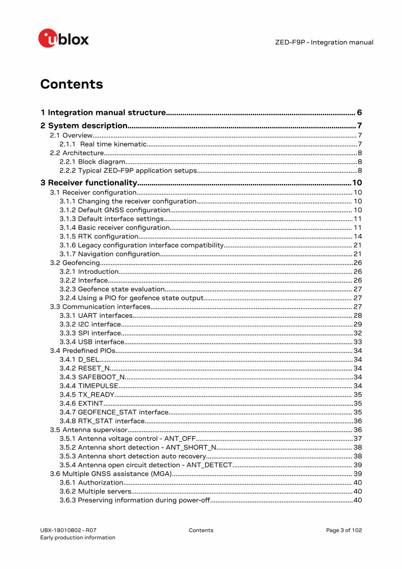
Contents
1 Integration manual structure............................................................................................ 6
2 System description...............................................................................................................72.1 Overview.................................................................................................................................................... 7
2.1.1 Real time kinematic......................................................................................................................72.2 Architecture..............................................................................................................................................8
2.2.1 Block diagram..................................................................................................................................82.2.2 Typical ZED-F9P application setups..........................................................................................8
3 Receiver functionality........................................................................................................103.1 Receiver configuration......................................................................................................................... 10
3.1.1 Changing the receiver configuration....................................................................................... 103.1.2 Default GNSS configuration...................................................................................................... 103.1.3 Default interface settings..........................................................................................................113.1.4 Basic receiver configuration...................................................................................................... 113.1.5 RTK configuration........................................................................................................................ 143.1.6 Legacy configuration interface compatibility........................................................................ 213.1.7 Navigation configuration............................................................................................................ 21
3.2 Geofencing..............................................................................................................................................263.2.1 Introduction................................................................................................................................... 263.2.2 Interface......................................................................................................................................... 263.2.3 Geofence state evaluation......................................................................................................... 273.2.4 Using a PIO for geofence state output................................................................................... 27
3.3 Communication interfaces................................................................................................................. 273.3.1 UART interfaces........................................................................................................................... 283.3.2 I2C interface..................................................................................................................................293.3.3 SPI interface..................................................................................................................................323.3.4 USB interface................................................................................................................................ 33
3.4 Predefined PIOs.....................................................................................................................................343.4.1 D_SEL..............................................................................................................................................343.4.2 RESET_N........................................................................................................................................ 343.4.3 SAFEBOOT_N................................................................................................................................343.4.4 TIMEPULSE................................................................................................................................... 343.4.5 TX_READY..................................................................................................................................... 353.4.6 EXTINT............................................................................................................................................353.4.7 GEOFENCE_STAT interface....................................................................................................... 353.4.8 RTK_STAT interface.....................................................................................................................36
3.5 Antenna supervisor.............................................................................................................................. 363.5.1 Antenna voltage control - ANT_OFF........................................................................................373.5.2 Antenna short detection - ANT_SHORT_N............................................................................ 383.5.3 Antenna short detection auto recovery.................................................................................. 383.5.4 Antenna open circuit detection - ANT_DETECT................................................................... 39
3.6 Multiple GNSS assistance (MGA)..................................................................................................... 393.6.1 Authorization................................................................................................................................ 403.6.2 Multiple servers............................................................................................................................ 403.6.3 Preserving information during power-off................................................................................40
UBX-18010802 - R07
Contents Page 3 of 102Early production information

ZED-F9P - Integration manual
3.6.4 AssistNow Online......................................................................................................................... 403.7 Clocks and time.....................................................................................................................................44
3.7.1 Receiver local time.......................................................................................................................443.7.2 Navigation epochs....................................................................................................................... 443.7.3 iTOW timestamps........................................................................................................................453.7.4 GNSS times................................................................................................................................... 453.7.5 Time validity.................................................................................................................................. 463.7.6 UTC representation..................................................................................................................... 463.7.7 Leap seconds................................................................................................................................ 473.7.8 Real time clock............................................................................................................................. 473.7.9 Date.................................................................................................................................................47
3.8 Timing functionality............................................................................................................................. 483.8.1 Time pulse..................................................................................................................................... 483.8.2 Timemark.......................................................................................................................................52
3.9 Security................................................................................................................................................... 533.9.1 Spoofing detection / monitoring...............................................................................................533.9.2 Jamming/interference indicator...............................................................................................543.9.3 GNSS receiver integrity.............................................................................................................. 55
3.10 u-blox protocol feature descriptions.............................................................................................. 553.10.1 Broadcast navigation data...................................................................................................... 55
3.11 Forcing a receiver reset.....................................................................................................................61
4 Design..................................................................................................................................... 634.1 Pin assignment......................................................................................................................................634.2 Power supply..........................................................................................................................................65
4.2.1 VCC: Main supply voltage.......................................................................................................... 654.2.2 V_BCKP: Backup supply voltage............................................................................................... 654.2.3 ZED-F9P power supply............................................................................................................... 66
4.3 ZED-F9P minimal design.................................................................................................................... 664.4 Antenna...................................................................................................................................................67
4.4.1 Antenna bias................................................................................................................................. 694.5 EOS/ESD precautions.......................................................................................................................... 71
4.5.1 ESD protection measures.......................................................................................................... 714.5.2 EOS precautions...........................................................................................................................724.5.3 Safety precautions...................................................................................................................... 72
4.6 Electromagnetic interference on I/O lines.......................................................................................724.6.1 General notes on interference issues...................................................................................... 734.6.2 In-band interference mitigation................................................................................................734.6.3 Out-of-band interference........................................................................................................... 74
4.7 Layout...................................................................................................................................................... 744.7.1 Placement...................................................................................................................................... 744.7.2 Package footprint, copper and paste mask........................................................................... 744.7.3 Layout guidance........................................................................................................................... 76
4.8 Design guidance....................................................................................................................................784.8.1 General considerations............................................................................................................... 784.8.2 Backup battery............................................................................................................................. 784.8.3 RF front-end circuit options...................................................................................................... 784.8.4 Antenna/RF input........................................................................................................................ 794.8.5 Ground pads.................................................................................................................................. 804.8.6 Schematic design........................................................................................................................ 804.8.7 Layout design-in guideline......................................................................................................... 80
UBX-18010802 - R07
Contents Page 4 of 102Early production information
ZED-F9P - Integration manual
5 Product handling................................................................................................................. 815.1 ESD handling precautions.................................................................................................................. 815.2 Soldering................................................................................................................................................. 815.3 Tapes....................................................................................................................................................... 845.4 Reels........................................................................................................................................................ 855.5 Moisture sensitivity levels.................................................................................................................. 85
Appendix.................................................................................................................................... 86A Glossary......................................................................................................................................................86B RTCM ITRF geodetic models.................................................................................................................86C RTK configuration procedures with u-center.....................................................................................88
C.1 Base configuration with u-center................................................................................................ 88C.2 Rover configuration with u-center...............................................................................................92
D Stacked patch antenna..........................................................................................................................96
Related documents..............................................................................................................100
Revision history.................................................................................................................... 101
UBX-18010802 - R07
Contents Page 5 of 102Early production information
ZED-F9P - Integration manual
1 Integration manual structureThis document provides a wealth of information to enable a successful design with the ZED-F9Pmodule. The manual is structured according to system, software and hardware aspects.
The first section, "System description" outlines the basics of enabling RTK operation with the ZED-F9P. This is essential reading for anyone new to the device to enable them to understand a workingRTK implementation.
The following section "Receiver functionality" provides an exhaustive description of the receiver'sfunctionality. Beginning with the new configuration messages, both existing and new users shouldread this section to understand the new message types employed. Most of the following sub-sections should be familiar to existing users of u-blox positioning products, however some changesare introduced owing to the new configuration messages.
The sections from "Design" onwards address hardware options when designing the ZED-F9Pinto a new product. This part gives power supply recommendations and provides guidance forcircuit design and PCB lay-out assistance. The "Antenna" section provides design informationand recommendation for this important component. A final "Design guidance" section helps thedesigner to check that crucial aspects of the design-in process have been carried out.
The final section addresses the general product handling concerns giving guidance on ESDprecautions, production soldering considerations and module delivery tape and reel information.
UBX-18010802 - R07
1 Integrationmanual structure
Page 6 of 102Early production information

ZED-F9P - Integration manual
2 System description
2.1 OverviewThe ZED-F9P positioning module features the new u-blox F9 receiver platform, which providesmulti-band GNSS to high volume industrial applications in a compact form factor. The module withintegrated RTK enables precise navigation and automation of moving machinery in industrial andconsumer grade products in a small surface mounted form factor of only 17.0 x 22.0 x 2.4 mm.
2.1.1 Real time kinematicu-blox ZED-F9P high precision receiver takes GNSS precision to the next level:
• Delivers accuracy down to the centimeter level: 0.01m + 1 ppm CEP• Fast time to first fix and robust performance with multi-band, multi-constellation reception• Compatible with leading correction services for global coverage and versatility
Some typical applications for the ZED-F9P are shown below:
Figure 1: Typical applications for the ZED-F9P
2.1.1.1 Modes of operation
The ZED-F9P supports two modes of operation:
1. ZED-F9P operating as a base: It provides RTCM correction data to a ZED-F9P rover, or to anetwork of ZED-F9P rovers.
2. ZED-F9P operating as a rover: It receives RTCM correction data from a ZED-F9P operating asa base, or from a virtual reference service provider operating a network of base receivers.
2.1.1.2 NTRIP - networked transport of RTCM via internet protocol
Networked Transport of RTCM via internet protocol, or NTRIP, is a open standard protocol forstreaming differential data over the internet in accordance with specifications published by RTCM.
There are three major parts to the NTRIP system: The NTRIP client, the NTRIP server, and the NTRIPcaster:
1. The NTRIP server is a PC or on-board computer running NTRIP server softwarecommunicating directly with a GNSS reference station. The NTRIP server serves as the
UBX-18010802 - R07
2 System description Page 7 of 102Early production information

ZED-F9P - Integration manual
intermediary between the GNSS receiver (NTRIP Source) streaming RTCM data and theNTRIP caster.
2. The NTRIP caster is an HTTP server which receives streaming RTCM data from one or moreNTRIP servers and in turn streams the RTCM data to one or more NTRIP clients via theinternet.
3. The NTRIP client receives streaming RTCM data from the NTRIP caster to apply as real-timecorrections to a GNSS rover.
u-center GNSS evaluation software provides an NTRIP client and server application that can beused to easily evaluate a ZED-F9P base or rover. Typically a u-center NTRIP client connects overthe internet to an NTRIP service provider. The u-center NTRIP client then provides the RTCM 3.3corrections to a ZED-F9P rover connected to the local u-center application. Virtual reference serviceis also supported by the u-center NTRIP client.
2.2 ArchitectureThe ZED-F9P receiver provides all the necessary RF and baseband processing to enable multi-band,multi-constellation operation. The block diagram below shows the key functionality.
2.2.1 Block diagram
Figure 2: ZED-F9P block diagram
An active antenna is mandatory with the ZED-F9P.
2.2.2 Typical ZED-F9P application setupsTwo application examples are illustrated below as typical system implementations. Both arerepresentative of a simple "short baseline" set-up in which the base and rover receivers are within a
UBX-18010802 - R07
2 System description Page 8 of 102Early production information
ZED-F9P - Integration manual
few hundred meters of each other. Here a ZED-F9P is used as a base station providing correctionsto a ZED-F9P rover receiver.
Alternatively, the rover can use corrections provided over longer baselines from a correction streamdistributed as a subscription service. This method can use a single fixed reference source which islocal (within 50 km) to the rover receiver or via a virtual reference service in which corrections aresynthesized for the rovers location.
2.2.2.1 ZED-F9P in a drone application
Figure 3: ZED-F9P base and rover in a short baseline drone application
2.2.2.2 ZED-F9P in a robotic mower application
Figure 4: ZED-F9P base and rover in a short baseline robotic mower application
UBX-18010802 - R07
2 System description Page 9 of 102Early production information

ZED-F9P - Integration manual
3 Receiver functionalityThis section describes the ZED-F9P operational features and their configuration.
3.1 Receiver configurationThe ZED-F9P is fully configurable with UBX configuration interface keys. The configurationdatabase in the receiver's RAM holds the current configuration, which is used by the receiverat run-time. It is constructed on start-up of the receiver from several sources of configuration.The configuration interface and the available keys are described fully in the ZED-F9P Interfacedescription [2].
A configuration setting stored in RAM remains effective until power-down or reset. If stored inBBR (battery backed RAM), the setting will be used as long as the backup battery supply remains.Configuration settings can be saved permanently in flash memory.
The configuration interface has changed from earlier u-blox positioning receivers. Thereis some backwards compatibility, however, users are strongly advised to adopt theconfiguration interface described in this document. See legacy UBX-CFG message fieldsreference section in the ZED-F9P Interface description [2].
Configuration interface settings are held in a database consisting of separate configuration items.An item is made up of a pair consisting of a key ID and a value. Related items are grouped togetherand identified under a common group name: CFG-GROUP-*; a convention used in u-center andwithin this document. Within u-center, a configuration group is identified as "Group name" and theconfiguration item is identified as the "item name" under the "Generation 9 Configuration View" -"Advanced Configuration" view.
The UBX messages available to change or poll the configurations are the UBX-CFG-VALSET, UBX-CFG-VALGET, and UBX-CFG-VALDEL messages. For more information about these messages andthe configuration keys see the configuration interface section in the ZED-F9P Interface description[2].
3.1.1 Changing the receiver configurationAll configuration messages, including legacy UBX-CFG messages, will result in a UBX-ACK-ACKor UBX-ACK-NAK response. If several configuration messages are sent without waiting for thisresponse then the receiver may pause processing of input messages until processing of a previousconfiguration message has been completed. When this happens a warning message "wait for cfgACK" will be sent to the host.
3.1.2 Default GNSS configurationThe ZED-F9P default GNSS configuration is set as follows:
• GPS: L1C/A, L2C• GLONASS: L1OF, L2OF• Galileo: E1B/C, E5b• BeiDou: B1I, B2I• QZSS: L1C/A, L2C
UBX-18010802 - R07
3 Receiver functionality Page 10 of 102Early production information

ZED-F9P - Integration manual
For more information about default configuration, see the ZED-F9P Interface description [2].
3.1.3 Default interface settingsInterface Settings
UART1 output 38400 baud, 8 bits, no parity bit, 1 stop bit.
NMEA protocol enabled and GGA, GLL, GSA, GSV, RMC, VTG, TXT messages are output by default.
UBX and RTCM 3.3 protocols are enabled but no output messages are enabled.
UART1 input 38400 baud, 8 bits, no parity bit, 1 stop bit.
UBX, NMEA and RTCM 3.3 input protocols are enabled by default.
UART2 output 38400 baud, 8 bits, no parity bit, 1 stop bit.
UBX protocol cannot be enabled on UART2.
RTCM 3.3 protocol is enabled by default but no output messages are enabled.
NMEA protocol is not enabled by default, it can be enabled and output messages can be enabled.
UART2 input 38400 baud, 8 bits, no parity bit, 1 stop bit.
UBX protocol cannot be enabled on UART2, will not receive UBX input messages.
RTCM 3.3 protocol enabled by default.
NMEA protocol disabled by default but can be enabled.
USB output NMEA protocol enabled and GGA, GLL, GSA, GSV, RMC, VTG, TXT messages are output by default.
UBX protocol is enabled but no messages are output by default.
RTCM 3.3 protocol enabled but no messages are output by default.
USB input UBX, NMEA, RTCM 3.3 protocols enabled by default.
I2C Fully compatible with the I2C1 industry standard, available for communication with an externalhost CPU or u-blox cellular modules, operated in slave mode only. Default messages activated asin UART1. Input/output protocols available as in UART1. Maximum bit rate 400 kb/s.
SPI Allow communication to a host CPU, operated in slave mode only. Default messages activated asin UART1. Input/output protocols available as in UART1. SPI is not available unless D_SEL pin isset to low (see the D_SEL section).
Table 1: Default interface settings
With firmware versions HPG 1.00 or later UART2 can function as the main correction interface;RTCM 3.3 is the default input and output protocol. UART2 can also optionally be configured forNMEA input or output protocol.
Refer to the u-blox ZED-F9P Interface description [2] for information about furthersettings.
If the base receiver is configured to output RTCM messages on several ports, they must all havethe same RTCM message and message rate configuration otherwise the MSM multiple messagebit might not be set properly.
By default the ZED-F9P outputs NMEA 4.10 messages that include satellite data for all GNSS bandsbeing received. This results in a high NMEA load output for each navigation period. Make sure theUART1 baud rate being used is sufficient for the selected navigation rate and the number of GNSSsignals being received.
3.1.4 Basic receiver configurationThis section summarizes the basic receiver configuration most commonly used.
1 I2C is a registered trademark of Philips/NXP
UBX-18010802 - R07
3 Receiver functionality Page 11 of 102Early production information

ZED-F9P - Integration manual
3.1.4.1 Communication interface configuration
Several configuration groups allow operation mode configuration of the various communicationinterfaces. These include parameters for the data framing, transfer rate and enabled input/outputprotocols. See Communication interfaces section for details. The configuration groups available foreach interface are:
Interface Configuration groups
UART1 CFG-UART1-*, CFG-UART1INPROT-*, CFG-UART1OUTPROT-*
UART2 CFG-UART2-*, CFG-UART2INPROT-*, CFG-UART2OUTPROT-*
USB CFG-USB-*, CFG-USBINPROT-*, CFG-USBOUTPROT-*
I2C CFG-I2C-*, CFG-I2CINPROT-*, CFG-I2COUTPROT-*
SPI CFG-SPI-*, CFG-SPIINPROT-*, CFG-SPIOUTPROT-*
Table 2: Interface configurations
3.1.4.2 Message output configuration
The rate of NMEA, UBX and RTCM protocol output messages are configurable.
If the rate configuration value is zero, then the corresponding message will not be output. Valuesgreater than zero indicate how often the message is output.
For periodic output messages the rate relates to the event the message is related to. For example,the UBX-NAV-PVT (navigation position velocity and time solution) is related to the navigation epoch.If the rate of this message is set to one (1), it will be output for every navigation epoch. If the rateis set to two (2), it will be output every other navigation epoch. The rates of the output messagesare individually configurable per communication interface. See the CFG-MSGOUT-* configurationgroup.
Some messages, such as UBX-MON-VER, are not periodic and will only be output as an answer toa poll request.
The UBX-INF-* and NMEA-Standard-TXT information messages are non-periodic output messagesthat do not have a message rate configuration. Instead they can be enabled for each communicationinterface via the CFG-INFMSG-* configuration group.
All message output is additionally subject to the protocol configuration of thecommunication interfaces. Messages of a given protocol will not be output until the protocolis enabled for output on the interface (see the previous section).
3.1.4.3 GNSS signal configuration
The GNSS constellations and bands are configurable with configuration keys from configurationgroup CFG-SIGNAL-*. Each GNSS constellation can be enabled or disabled independently. A GNSSconstellation is considered to be enabled when the constellation enable key is set and at least oneof the constellation's band keys is enabled.
ZED-F9P only supports certain combinations of constellations and bands. For all constellations,both L1 and L2 bands must either be enabled or disabled. BeiDou B2 is the exception (can eitherhave BeiDou B1+B2 or B1-only). Unsupported combinations will be rejected with a UBX-ACK-NAKand the warning: "invalid sig cfg" will be sent via UBX-INF and NMEA-TXT messages (if enabled).
The following table shows possible configuration key combinations for the GPS constellation.
Constellation key
CFG-SIGNAL-GPS_ENA
Band key
CFG-SIGNAL-GPS_L1CA_ENA
Band key
CFG-SIGNAL-GPS_L2C_ENA
Constellationenabled?
false (0) false (0) false (0) no
UBX-18010802 - R07
3 Receiver functionality Page 12 of 102Early production information

ZED-F9P - Integration manual
Constellation key
CFG-SIGNAL-GPS_ENA
Band key
CFG-SIGNAL-GPS_L1CA_ENA
Band key
CFG-SIGNAL-GPS_L2C_ENA
Constellationenabled?
false (0) false (0) true (1) no
false (0) true (1) false (0) no
false (0) true (1) true (1) no
true (1) false (0) false (0) no
true (1) false (0) true (1) Unsupportedcombination
true (1) true (1) false (0) Unsupportedcombination
true (1) true (1) true (1) yes
Table 3: Example of possible values of configuration items for the GPS constellation
3.1.4.4 Antenna supervisor configuration
This section describes the antenna supervisor configuration, its use and restrictions.
The antenna supervisor is used to control an active antenna. The configuration of the antennasupervisor allows the following:
• Control voltage supply to the antenna, which allows the antenna supervisor to cut power to theantenna in the event of a short circuit or optimize power to the antenna in power save mode
• Detect a short circuit in the antenna and auto recover the antenna supply in such event• Detect an open antenna, which can be used to tell if the antenna has been disconnected
See the table below for a description of the configuration items related to the antenna supervisoroperation.
Configuration item Description Comments
CFG-HW-ANT_CFG_VOLTCTRL Enable active antenna voltage control
CFG-HW-ANT_CFG_SHORTDET Enable short circuit detection
CFG-HW-ANT_CFG_SHORTDET_POL Short antenna detection polarity Set to 1 if the required logic polarity isactive-low (default)
CFG-HW-ANT_CFG_OPENDET Enable open circuit detection
CFG-HW-ANT_CFG_OPENDET_POL Open antenna detection polarity Set to 1 if the required logic polarity isactive-low (default)
CFG-HW-ANT_CFG_PWRDOWN Power down antenna supply if shortcircuit is detected
CFG-HW-ANT_CFG_PWRDOWN_POL Power down antenna logic polarity Set to 1 if the required logic polarity isactive-high (default)
CFG-HW-ANT_CFG_RECOVER Enable auto recovery in the event of ashort circuit
To use this feature, short circuitdetection should be enabled. See CFG-HW-ANT_CFG_SHORTDET
CFG-HW-ANT_SUP_SWITCH_PIN PIO-Pin (PIO number) used for switchingantenna supply
It is recommended that you use thedefault PIO and assigned pin
CFG-HW-ANT_SUP_SHORT_PIN PIO-Pin (PIO number) used for detectinga short-circuit in the antenna supply
It is recommended that you use thedefault PIO and assigned pin
CFG-HW-ANT_SHORT_THR Defines the threshold for the antennasupervisor when a short status isdetected.
Only applicable for the discreteantenna supervisor (based on MADC).
CFG-HW-ANT_OPEN_THR Defines the threshold for the antennasupervisor when a open status isdetected.
Only applicable for the discreteantenna supervisor (based on MADC).
UBX-18010802 - R07
3 Receiver functionality Page 13 of 102Early production information

ZED-F9P - Integration manual
Configuration item Description Comments
CFG-HW-ANT_ENGINE With this configuration key, the antennasupervisor engine can be selected.
Default value is "EXT".
Table 4: Antenna supervisor configuration
It is possible to obtain the status of the antenna supervisor through the UBX-MON-RF message.Moreover, any changes in the status of the antenna supervisor are reported to the host interface inthe form of notice messages. See the ZED-F9P Interface description [2] for antStatus and antPowerfield description.
Status Description
OFF Antenna is off
ON Antenna is on
DONTKNOW Antenna power status is not known
Table 5: Antenna power status
3.1.5 RTK configurationRTK technology introduces the concept of a base and a rover. In such a setup, the base sendscorrections (complying with the RTCM 3.3 protocol) to the rover via a communication link. Thisenables the rover to compute its position relative to the base with high accuracy.
While in the standard RTK mode, the base remains static in a known position, in the moving base(MB) RTK mode, both base and rover receivers can move. The latter is ideal for applications wherethe relative position offset between two moving vehicles is required such as, for example, the follow-me feature on a UAV.
In the MB RTK context, the base and rover receivers are referred to as MB base and MB roverrespectively.
When operating as a rover, the ZED-F9P can receive RTCM 3.3 corrections from another ZED-F9Poperating as a base, or via NTRIP from a virtual reference service provider operating a networkof base receivers. In this mode, the receiver coordinates will be expressed in the datum used bythe RTCM correction provider. For more information on this topic please refer to the RTCM ITRFGeodetic models section in the Appendix.
After describing the RTCM protocol and corresponding supported message types, this sectiondescribes how to configure the ZED-F9P high precision receiver as a base or rover receiver. Thisincludes both the static base use case and the moving base use case.
See the ZED-F9P Moving Base application note [4] for more information on designing in and usingmoving base.
3.1.5.1 RTCM corrections
RTCM is a binary data protocol for communication of GNSS correction information. The ZED-F9Phigh precision receiver supports RTCM as specified by RTCM 10403.3, Differential GNSS (GlobalNavigation Satellite Systems) Services – Version 3 (October 7, 2016).
The RTCM specification is currently at version 3.3 and RTCM version 2 messages are not supportedby this standard.
To modify the RTCM input/output settings, see the configuration section in the u-blox ZED-F9PInterface description [2].
2 The terms base, base station, reference and reference station can be used interchangeably
UBX-18010802 - R07
3 Receiver functionality Page 14 of 102Early production information
ZED-F9P - Integration manual
Users should be aware of the datum used by the correction source. The rover position will providecoordinates in the correction source reference frame. This may need to be taken into account whenusing the RTK rover position. See the RTCM ITRF Geodetic models section in the Appendix for moreinformation.
3.1.5.2 List of supported RTCM input messages
Message Type Description
RTCM 1001 L1-only GPS RTK observables
RTCM 1002 Extended L1-only GPS RTK observables
RTCM 1003 L1/L2 GPS RTK observables
RTCM 1004 Extended L1/L2 GPS RTK observables
RTCM 1005 Stationary RTK reference station ARP
RTCM 1006 Stationary RTK reference station ARP with antenna height
RTCM 1007 Antenna descriptor
RTCM 1009 L1-only GLONASS RTK observables
RTCM 1010 Extended L1-only GLONASS RTK observables
RTCM 1011 L1/L2 GLONASS RTK observables
RTCM 1012 Extended L1/L2 GLONASS RTK observables
RTCM 1033 Receiver and Antenna Description
RTCM 1074 GPS MSM4
RTCM 1075 GPS MSM5
RTCM 1077 GPS MSM7
RTCM 1084 GLONASS MSM4
RTCM 1085 GLONASS MSM5
RTCM 1087 GLONASS MSM7
RTCM 1094 Galileo MSM4
RTCM 1095 Galileo MSM5
RTCM 1097 Galileo MSM7
RTCM 1124 BeiDou MSM4
RTCM 1125 BeiDou MSM5
RTCM 1127 BeiDou MSM7
RTCM 1230 GLONASS code-phase biases
RTCM 4072.0 Reference station PVT (u-blox proprietary RTCM Message)
RTCM 4072.1 Additional reference station information (u-blox proprietary RTCM Message)
Table 6: ZED-F9P supported input RTCM version 3.3 messages
3.1.5.3 List of supported RTCM output messages
Message Description
RTCM 1005 Stationary RTK reference station ARP
RTCM 1074 GPS MSM4
RTCM 1077 GPS MSM7
RTCM 1084 GLONASS MSM4
RTCM 1087 GLONASS MSM7
RTCM 1094 Galileo MSM4
RTCM 1097 Galileo MSM7
RTCM 1124 BeiDou MSM4
UBX-18010802 - R07
3 Receiver functionality Page 15 of 102Early production information

ZED-F9P - Integration manual
Message Description
RTCM 1127 BeiDou MSM7
RTCM 1230 GLONASS code-phase biases
RTCM 4072.0, subtype 0 Reference station PVT (u-blox proprietary RTCM Message)
RTCM 4072.1, subtype 1 Additional reference station information (u-blox proprietary RTCM Message)
Table 7: ZED-F9P supported output RTCM version 3.3 messages
3.1.5.4 Rover operation
In its default configuration, the ZED-F9P high precision receiver will attempt to provide the bestpositioning accuracy depending on the received correction data. It will enter RTK float mode as soonas it receives an input stream of RTCM correction messages. Once the rover has resolved the carrierphase ambiguities, it will enter RTK fixed mode. When in this mode, the relative position accuracybetween base and rover can be expected to be correct to the cm-level. The time period between RTKfloat and RTK fixed operation is referred to as the convergence time. Note that the convergence timeis affected by the baseline length as well as by multipath and satellite visibility at both rover andbase station.
The ZED-F9P high precision receiver should receive RTCM corrections matching its GNSS signalconfiguration to function optimally. The rover requires both base station observation (MSM 7messages) and position messages (RTCM 4072.0, RTCM 4072.1) in order to attempt ambiguityfixes. The rover will attempt to provide RTK fixed operation when five or more ambiguities can beestimated. If phase lock on the minimum amount of signals cannot be maintained, the rover willdrop back to RTK float mode. The rover will continue to attempt to resolve carrier ambiguities andrevert to RTK fixed mode once the minimum number of signals has been restored.
The RTK mode that an RTK rover operates in can be configured through the CFG-NAVHPG-DGNSSMODE configuration item. The two following RTK modes are available:
• RTK fixed: The rover will attempt to fix ambiguities whenever possible.• RTK float: The rover will estimate the ambiguities as float but will make no attempts at fixing
them.
The time after which RTCM data will be discarded can be configured through the CFG-NAVSPG-CONSTR_DGNSSTO configuration item.
The received correction messages stream should comply with the following:
• The reference station ID in the reference station message must match that used in theobservation messages. Otherwise, the rover cannot compute its position.
• In order to fix GLONASS ambiguities the correction stream must contain message 1230or 1033. Otherwise, the carrier ambiguities will be estimated as float even when set tooperate in RTK fixed mode. This will result in degraded performance, especially in challengingenvironments.
3.1.5.4.1 Message output in RTK modeWhen operating in MB RTK rover mode users should take note of the modified information withinthe following NMEA and UBX messages:
• NMEA-GGA: The quality field will be 4 for RTK fixed and 5 for RTK float (see NMEA position fixflags in interface description). The age of differential corrections and base station ID will be set.
• NMEA-GLL, NMEA-VTG: The posMode indicator will be D for RTK float and RTK fixed (seeNMEA position fix flags in interface description).
• NMEA-RMC, NMEA-GNS: The posMode indicator will be F for RTK float and R for RTK fixed (seeNMEA position fix flags in interface description).
• UBX-NAV-PVT: The carrSoln flag will be set to 1 for RTK float and 2 for RTK fixed.
UBX-18010802 - R07
3 Receiver functionality Page 16 of 102Early production information

ZED-F9P - Integration manual
• UBX-NAV-RELPOSNED• The diffSoln and refPosValid flags will be set. The carrSoln flag will be set to 1 for RTK float
and 2 for RTK fixed.• UBX-NAV-SAT
• The diffCorr flag will be set for satellites with valid RTCM data• The rtcmCorrUsed, prCorrUsed, and crCorrUsed flags will be set for satellites for which the
RTCM corrections have been applied• UBX-NAV-SIG
• For signals to which the RTCM corrections have been applied, the correction source will beset to RTCM3 OSR and the crUsed, prCorrUsed, and crCorrUsed flags will be set
• UBX-NAV-STATUS• The diffSoln flag and the diffCorr flag will be set
• If the baseline exceeds 50km, a UBX-INF-WARNING will be output, e.g. "WARNING: DGNSS longbaseline: 52.7 km"
An illustrated procedure for configuring a rover using u-center is shown in the Appendix.
3.1.5.5 Stationary base operation
The ZED-F9P high precision receiver default operation begins without producing any RTCMmessages. RTCM observation messages will be streamed as soon as they are configured for output.However, any stationary reference position messages are output only when the base station positionhas been initialized and is operating in time mode. Time mode sets the receiver to operate as astationary base station in fixed position and only time is estimated.
The following procedures can be used to initialize the base station position:
• Use the built-in survey-in procedure to estimate the position.• Enter coordinates independently generated or taken from an accurate position such as a survey
marker.• Use in rover mode and feed the receiver corrections then enter the resultant estimated position
coordinates as above.
3.1.5.5.1 Survey-inSurvey-in is a procedure that is carried out prior to entering time mode. It estimates the receiverposition by building a weighted mean of all valid 3D position solutions.
Two major parameters are required when configuring:
• A minimum observation time defines the minimum observation time independent of theactual number of fixes used for the position estimate. Values can range from one day for highaccuracy requirements to a few minutes for coarse position determination.
• A 3D position standard deviation defines a limit on the spread of positions that contribute tothe calculated mean.
Survey-in ends when both requirements are successfully met. The receiver begins operation in timemode and can output a base position message if configured. The survey-in status can be queriedusing the UBX-NAV-SVIN message.
The base station receiver should not be fed RTCM corrections while it is in survey-in mode.If a corrected position is desired, the base station coordinates should be pre-surveyed usingRTCM corrections; the resultant position can be used to set the base station in fixed mode.
To configure a base station into survey-in mode (CFG-TMODE-MODE=SURVEY_IN), the followingitems are required:
UBX-18010802 - R07
3 Receiver functionality Page 17 of 102Early production information
ZED-F9P - Integration manual
Configuration item Description
CFG-TMODE-MODE Receiver mode (disabled, survey-in or fixed)
CFG-TMODE-SVIN_MIN_DUR Survey-in minimum duration
CFG-TMODE-SVIN_ACC_LIMIT Survey-in position accuracy limit
Table 8: Configuration items used for setting a base station into survey-in mode
3.1.5.5.2 Fixed positionHere the receiver position coordinates are entered manually. Any error in the base station positionwill directly translate into rover position errors. The base station position accuracy should thereforematch or exceed the desired rover absolute position accuracy.
To configure Fixed mode (CFG-TMODE-MODE=FIXED), the following items are relevant:
Configuration item Description
CFG-TMODE-MODE Receiver mode (disabled or survey-in or fixed)
CFG-TMODE-POS_TYPE Determines whether the ARP position is given in ECEF or LAT/LON/HEIGHT
CFG-TMODE-ECEF_X ECEF X coordinate of the ARP position
CFG-TMODE-ECEF_Y ECEF Y coordinate of the ARP position
CFG-TMODE-ECEF_Z ECEF Z coordinate of the ARP position
CFG-TMODE-LAT Latitude of the ARP position
CFG-TMODE-LON Longitude of the ARP position
CFG-TMODE-HEIGHT Height of the ARP position
CFG-TMODE-ECEF_X_HP High-precision ECEF X coordinate of the ARP position
CFG-TMODE-ECEF_Y_HP High-precision ECEF Y coordinate of the ARP position
CFG-TMODE-ECEF_Z_HP High-precision ECEF Z coordinate of the ARP position
CFG-TMODE-LAT_HP High-precision latitude of the ARP position
CFG-TMODE-LON_HP High-precision longitude of the ARP position
CFG-TMODE-HEIGHT_HP High-precision height of the ARP position
CFG-TMODE-FIXED_POS_ACC Fixed position 3D accuracy estimate
Table 9: Configuration items used for setting a base station into fixed mode
Once the receiver is set in fixed mode, select the position format to use: either LLH or ECEF withoptional high precision (mm) coordinates compared to the standard cm value.
For example, with CFG-TMODE-POS_TYPE=ECEF the base antenna position can be enteredto cm precision using CFG-TMODE-ECEF_X, CFG-TMODE-ECEF_Y, CFGTMODE-ECEF_Z. Forhigh precision (mm) coordinates use CFG-TMODEECEF_X_HP, CFG-TMODE-ECEF_Y_HP, CFG-TMODE-ECEF_Z_HP. The same applies with corresponding coordinates used with CFG-TMODE-POS_TYPE=LLH.
The "3D accuracy" estimate in "Fixed Position" and the "Position accuracy limit" in "Survey-in" willaffect the rover absolute position accuracy. Note that the availability of the position accuracy doesnot mitigate the error in the rover position, but only accounts for it when calculating the resultingpositioning accuracy.
In stationary base station mode a current position check is made with respect to the fixedcoordinates. If the result indicates the fixed position coordinates are incorrect, a UBX-INF-WARNING message "Base station position seems incorrect" is issued. The message isoutput when the coordinates are incorrect by more than ~50 m up to 25 km.
If the base station is moved during operation then new position coordinates must beconfigured.
UBX-18010802 - R07
3 Receiver functionality Page 18 of 102Early production information

ZED-F9P - Integration manual
An illustrated procedure for configuring a base receiver using u-center is shown in the Appendix.
3.1.5.5.3 Base station: RTCM output configurationThe desired RTCM messages must be selected and configured for the corresponding GNSSconstellations received. The recommended list of RTCM output messages for a base operating indefault GNSS configuration are:
• RTCM 1005 Stationary RTK reference station ARP• RTCM 1074 GPS MSM4• RTCM 1084 GLONASS MSM4• RTCM 1094 Galileo MSM4• RTCM 1124 BeiDou MSM4• RTCM 1230 GLONASS code-phase biases
The configuration messages for these are shown in the Table 10.
The following configuration items output the recommended messages for a default satelliteconstellation setting. Note that these are given for the UART1 interface:
Configuration item Description
CFG-MSGOUT-RTCM_3X_TYPE1005_UART1
Output rate of the RTCM-3X-TYPE1005 message on port UART1: RTCM basestation message
CFG-MSGOUT-RTCM_3X_TYPE1074_UART1
Output rate of the RTCM-3X-TYPE1074 message on port UART1: RTCM GPSMSMS4 message
CFG-MSGOUT-RTCM_3X_TYPE1084_UART1
Output rate of the RTCM-3X-TYPE1084 message on port UART1: RTCM GLONASSMSM4 message
CFG-MSGOUT-RTCM_3X_TYPE1094_UART1
Output rate of the RTCM-3X-TYPE1094 message on port UART1: RTCM GalileoMSM4 message
CFG-MSGOUT-RTCM_3X_TYPE1124_UART1
Output rate of the RTCM-3X-TYPE1124 message on port UART1: RTCM BeiDouMSM4 message
CFG-MSGOUT-RTCM_3X_TYPE1230_UART1
Output rate of the RTCM-3X-TYPE1230 message on port UART1: RTCM GLONASSbias message
Table 10: Configuration items used for typical RTCM output configuration on UART1
The configuration of the RTCM 3.3 correction stream must be made with the following guidance:
• All observation messages must be broadcast at the same rate.• The RTCM 3.3 correction stream must contain the GLONASS code-phase biases message
(type 1230) or the Receiver Antenna Description message (type 1033) otherwise the GLONASSambiguities can only be estimated as float, even in RTK fixed mode.
• The static reference station message (type 1005 or type 1006) does not need to be broadcastat the same rate as the observation messages however a rover will not be able to compute itsposition until it has received a valid reference station message.
• The correction stream should only contain one type of observation messages per constellation.When using a multi-constellation configuration, all constellations should use the same type ofobservation messages. Mixing RTK and MSM messages will result in undefined rover behavior.
• If the receiver is configured to output RTCM messages on several ports, they must all have thesame RTCM configuration otherwise the MSM multiple message bit might not be set properly.
3.1.5.6 Base and rover configuration for moving base RTK operation
The MB mode differs from the standard RTK operation in that the base station is no longerstationary at a pre-determined location. Both the reference station and rover receivers are allowedto move while computing an accurate vector between the receiver antennas. This mode enables thecalculation of heading on dynamic or static platforms, plus provides a centimeter level accurate 3Dvector for use in dynamic positioning applications, e.g. a UAV ”follow me” feature.
UBX-18010802 - R07
3 Receiver functionality Page 19 of 102Early production information

ZED-F9P - Integration manual
This section describes how to configure the ZED-F9P high precision receiver in a moving base setup.
3.1.5.6.1 Base operation in MB RTK modeIn addition to the rules described in RTCM output configuration section above, the following movingbase specific rules apply:
• The RTCM 3.3 stream must contain reference station message 4072 sub-type 0 (positioninformation) and MSM7 observation messages, otherwise the rover will be unable to operate inMB rover mode.
• It is recommended to include message 4072 sub-type 1 (timing information) as this willimprove RTK rover timing performance.
• Messages of type 4072 must be sent for each epoch the MB base observations are sent.• To ensure that the baseline is as accurate as possible, the MB base and rover must use the
same navigation update rate.
The desired RTCM messages must be selected and configured for the corresponding GNSSconstellations received. The recommended list of RTCM output messages for a base operating inMB configuration are:
• RTCM 4072.0 Reference station PVT information• RTCM 4072.1 Reference station timing information• RTCM 1077 GPS MSM7• RTCM 1087 GLONASS MSM7• RTCM 1097 Galileo MSM7• RTCM 1127 BeiDou MSM7• RTCM 1230 GLONASS code-phase biases
Additionally, while a MB receiver operates as a base, it is able to simultaneously:
• Apply RTCM 3.3 corrections and reach RTK fixed mode.• Generate a MB correction stream for accompanying MB rover(s).
3.1.5.6.2 Rover operation in MB RTK modeWhile the MB RTK solution aims at estimating the relative position with centimeter-level accuracy,the absolute position of each receiver is expected to be known with a standard GNSS accuracy of afew meters, unless the base is receiving RTCM 3.3 corrections.
In addition to the rules described in the rover operation section, the following moving base specificrules apply:
• A moving base receiver typically experiences worse GNSS tracking than a static base receiver inan open-sky environment and therefore the MB RTK performance may be degraded.
• The MB rover can only compute an optimal MB RTK solution if the time-matched RTCMobservation and position messages are received within a predefined time limit. The MB roverwill wait up to 700 ms for messages before falling back to an extrapolated MB RTK solution.The MB rover will extrapolate the MB reference observations and/or position for up to 3 s beforefalling back to standard GNSS operation.
• The achievable update rate of the MB RTK solution is limited by the communication linklatency. As a rule of thumb, the communication link latency should be about half the desirednavigation update period. If it exceeds 700 ms, the MB rover will not be able to compute an MBRTK solution, even at 1 Hz.
• Since the MB rover must wait for time-matched RTCM corrections from the MB RTK baseto compute its position, the overall latency of the MB RTK solution will be the sum of thecommunication link latency plus the MB RTK computation time.
In addition to the modified output described in the rover operation section, the following movingbase output message modifications will be observed:
UBX-18010802 - R07
3 Receiver functionality Page 20 of 102Early production information

ZED-F9P - Integration manual
UBX-NAV-RELPOSNED:
• The isMoving flag will be set• The refPosMiss and refObsMiss flags will be set for epochs during which extrapolated base
position or observations have been used• The baselineValid will be set, unless extrapolated observations have been used• The heading for the relative position vector and its accuracy will be output, the
relPosHeadingValid flag will be set, unless the length of the relative position vector and/or itsaccuracy are not sufficient to reliably derive the heading information
CFG-NAVSPG-CONSTR_DGNSSTO:
As discussed above, RTCM corrections can only be extrapolated over a few seconds when both baseand rover receivers are moving. Therefore, any value set using this configuration key will be ignoredby the MB rover.
3.1.6 Legacy configuration interface compatibilityThere is some backwards-compatibility for the legacy UBX-CFG configuration messages. It isstrongly recommended to adopt the new configuration interface, as the legacy configurationmessages support will be removed in the future.
See Legacy UBX-CFG message fields reference section in the ZED-F9P Interface description [2].
3.1.7 Navigation configurationThis section presents various configuration options related to the navigation engine. These optionscan be configured through various configuration groups, such as CFG-NAVSPG-*, CFG-ODO-*, andCFG-MOT-*.
3.1.7.1 Platform settings
u-blox receivers support different dynamic platform models (see in the table below) to adjustthe navigation engine to the expected application environment. These platform settings can bechanged dynamically without performing a power cycle or reset. The settings improve the receiver'sinterpretation of the measurements and thus provide a more accurate position output. Setting thereceiver to an unsuitable platform model for the given application environment is likely to result ina loss of receiver performance and position accuracy.
The dynamic platform model can be configured through the CFG-NAVSPG-DYNMODELconfiguration item. The supported dynamic platform models and their details can be seen in Table11 and Table 12 below.
Platform Description
Portable (default) Applications with low acceleration, e.g. portable devices. Suitable for most situations.
Stationary Used in timing applications (antenna must be stationary) or other stationary applications.Velocity restricted to 0 m/s. Zero dynamics assumed.
Pedestrian Applications with low acceleration and speed, e.g. how a pedestrian would move. Lowacceleration assumed.
Automotive Used for applications with equivalent dynamics to those of a passenger car. Low verticalacceleration assumed.
At sea Recommended for applications at sea, with zero vertical velocity. Zero vertical velocity assumed.Sea level assumed.
Airborne <1g Used for applications with a higher dynamic range and greater vertical acceleration than apassenger car. No 2D position fixes supported.
Airborne <2g Recommended for typical airborne environments. No 2D position fixes supported.
UBX-18010802 - R07
3 Receiver functionality Page 21 of 102Early production information

ZED-F9P - Integration manual
Platform Description
Airborne <4g Only recommended for extremely dynamic environments. No 2D position fixes supported.
Wrist Only recommended for wrist-worn applications. Receiver will filter out arm motion.
Table 11: Dynamic platform models
Platform Max altitude [m] Max horizontalvelocity [m/s]
Max vertical velocity[m/s]
Sanity check type Maxpositiondeviation
Portable 12000 310 50 Altitude and velocity Medium
Stationary 9000 10 6 Altitude and velocity Small
Pedestrian 9000 30 20 Altitude and velocity Small
Automotive 6000 100 15 Altitude and velocity Medium
At sea 500 25 5 Altitude and velocity Medium
Airborne <1g 50000 100 100 Altitude Large
Airborne <2g 50000 250 100 Altitude Large
Airborne <4g 50000 500 100 Altitude Large
Wrist 9000 30 20 Altitude and velocity Medium
Table 12: Dynamic platform model details
Dynamic platforms designed for high acceleration systems (e.g. airborne <2g) can result in a higherstandard deviation in the reported position.
If a sanity check against a limit of the dynamic platform model fails, then the position solutionis invalidated. Table 12 above shows the types of sanity checks which are applied for a particulardynamic platform model.
3.1.7.2 Navigation input filters
The navigation input filters in CFG-NAVSPG-* configuration group provide the input data of thenavigation engine.
Configuration item Description
CFG-NAVSPG-FIXMODE By default, the receiver calculates a 3D position fix if possible but reverts to 2Dposition if necessary (auto 2D/3D). The receiver can be forced to only calculate 2D(2D only) or 3D (3D only) positions.
CFG-NAVSPG-CONSTR_ALT, CFG-NAVSPG-CONSTR_ALTVAR
The fixed altitude is used if fixMode is set to 2D only. A variance greater than zeromust also be supplied.
CFG-NAVSPG-INFIL_MINELEV Minimum elevation of a satellite above the horizon in order to be used in thenavigation solution. Low elevation satellites may provide degraded accuracy, due tothe long signal path through the atmosphere.
CFG-NAVSPG-INFIL_NCNOTHRS,CFG-NAVSPG-INFIL_CNOTHRS
A navigation solution will only be attempted if there are at least the given number ofSVs with signals at least as strong as the given threshold.
Table 13: Navigation input filter parameters
If the receiver only has three SVs for calculating a position, the navigation algorithm uses a constantaltitude to compensate for the missing fourth SV. When a SV is lost after a successful 3D fix (min.four SVs available), the altitude is kept constant at the last known value. This is called a 2D fix.
u-blox receivers do not calculate any navigation solution with less than three SVs.
3.1.7.3 Navigation output filters
The result of a navigation solution is initially classified by the fix type (as detailed in the fixTypefield of UBX-NAV-PVT message). This distinguishes between failures to obtain a fix at all ("No Fix")
UBX-18010802 - R07
3 Receiver functionality Page 22 of 102Early production information

ZED-F9P - Integration manual
and cases where a fix has been achieved, which are further subdivided into specific types of fixes(e.g. 2D, 3D, dead reckoning).
The ZED-F9P firmware does not support the dead reckoning position fix type.
Where a fix has been achieved, a check is made to determine whether the fix should be classified asvalid or not. A fix is only valid if it passes the navigation output filters as defined in CFG-NAVSPG-OUTFIL. In particular, both PDOP and accuracy values must be below the respective limits.
Important: Users are recommended to check the gnssFixOK flag in the UBX-NAV-PVT orthe NMEA valid flag. Fixes not marked valid should not be used.
UBX-NAV-STATUS message also reports whether a fix is valid in the gpsFixOK flag. Thesemessages have only been retained for backwards compatibility and users are recommended to usethe UBX-NAV-PVT message.
The CFG-NAVSPG-OUTFIL_TDOP and CFG-NAVSPG-OUTFIL_TACC configuration items also defineTDOP and time accuracy values that are used in order to establish whether a fix is regarded as lockedto GNSS or not, and as a consequence of this, which time pulse setting has to be used. Fixes thatdo not meet both criteria will be regarded as unlocked to GNSS, and the corresponding time pulsesettings of CFG-TP-* configuration group will be used to generate a time pulse.
When in RTK float/fixed mode there are no navigation output filter settings for this mode.This is handled internally in the RTK core.
3.1.7.3.1 Speed (3D) low-pass filterThe CFG-ODO-OUTLPVEL configuration item offers the possibility to activate a speed (3D) low-pass
filter. The output of the speed low-pass filter is published in the UBX-NAV-VELNED message (speedfield). The filtering level can be set via the CFG-ODO-VELLPGAIN configuration item and must becomprised between 0 (heavy low-pass filtering) and 255 (weak low-pass filtering).
The internal filter gain is computed as a function of speed. Therefore, the level as defined inthe CFG-ODO-VELLPGAIN configuration item defines the nominal filtering level for speedsbelow 5 m/s.
3.1.7.3.2 Course over ground low-pass filterThe CFG-ODO-OUTLPCOG configuration item offers the possibility to activate a course over groundlow-pass filter when the speed is below 8 m/s. The output of the course over ground (also named
heading of motion 2D) low-pass filter is published in the UBX-NAV-PVT message (headMot field),
UBX-NAV-VELNED message (heading field), NMEA-RMC message (cog field) and NMEA-VTG
message (cogt field). The filtering level can be set via the CFG-ODO-COGLPGAIN configuration itemand must be comprised between 0 (heavy low-pass filtering) and 255 (weak low-pass filtering).
The filtering level as defined in the CFG-ODO-COGLPGAIN configuration item defines thefilter gain for speeds below 8 m/s. If the speed is higher than 8 m/s, no course over groundlow-pass filtering is performed.
3.1.7.3.3 Low-speed course over ground filterThe CFG-ODO-USE_COG activates this feature and the CFG-ODO-COGMAXSPEED, CFG-ODO-COGMAXPOSACC configuration items offer the possibility to configure a low-speed course overground filter (also named heading of motion 2D). This filter derives the course over ground fromposition at very low speed. The output of the low-speed course over ground filter is published in the
UBX-NAV-PVT message (headMot field), UBX-NAV-VELNED message (heading field), NMEA-RMC
message (cog field) and NMEA-VTG message (cogt field). If the low-speed course over ground filteris not configured, then the course over ground is computed as described in section Freezing thecourse over ground.
UBX-18010802 - R07
3 Receiver functionality Page 23 of 102Early production information
ZED-F9P - Integration manual
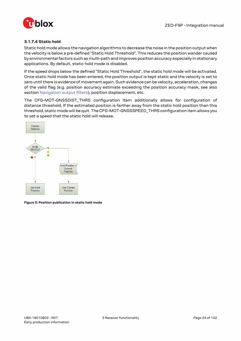
3.1.7.4 Static hold
Static hold mode allows the navigation algorithms to decrease the noise in the position output whenthe velocity is below a pre-defined "Static Hold Threshold". This reduces the position wander causedby environmental factors such as multi-path and improves position accuracy especially in stationaryapplications. By default, static hold mode is disabled.
If the speed drops below the defined "Static Hold Threshold", the static hold mode will be activated.Once static hold mode has been entered, the position output is kept static and the velocity is set tozero until there is evidence of movement again. Such evidence can be velocity, acceleration, changesof the valid flag (e.g. position accuracy estimate exceeding the position accuracy mask, see alsosection Navigation output filters), position displacement, etc.
The CFG-MOT-GNSSDIST_THRS configuration item additionally allows for configuration ofdistance threshold. If the estimated position is farther away from the static hold position than thisthreshold, static mode will be quit. The CFG-MOT-GNSSSPEED_THRS configuration item allows youto set a speed that the static hold will release.
Figure 5: Position publication in static hold mode
UBX-18010802 - R07
3 Receiver functionality Page 24 of 102Early production information

ZED-F9P - Integration manual
Figure 6: Flowchart of the static hold mode
3.1.7.5 Freezing the course over ground
If the low-speed course over ground filter is deactivated or inactive (see section Low-speed courseover ground filter), the receiver derives the course over ground from the GNSS velocity information.If the velocity cannot be calculated with sufficient accuracy (e.g., with bad signals) or if the absolutespeed value is very low (under 0.1 m/s) then the course over ground value becomes inaccurate too.In this case the course over ground value is frozen, i.e. the previous value is kept and its accuracyis degraded over time. These frozen values will not be output in the NMEA messages NMEA-RMCand NMEA-VTG unless the NMEA protocol is explicitly configured to do so (see NMEA protocolconfiguration in the ZED-F9P Interface description [2]).
UBX-18010802 - R07
3 Receiver functionality Page 25 of 102Early production information

ZED-F9P - Integration manual
Figure 7: Flowchart of the course over ground freezing
3.2 Geofencing
3.2.1 Introduction
Figure 8: Geofence
The geofencing feature allows for the configuration of up to four circular areas (geofences) on theEarth's surface. The receiver will then evaluate for each of these areas whether the current positionlies within the area or not and signal the state via UBX messaging and PIO toggling.
3.2.2 InterfaceGeofencing can be configured using the CFG-GEOFENCE-* configuration group. The geofenceevaluation is active whenever there is at least one geofence configured.
The current state of each geofence plus the combined state is output in UBX-NAV-GEOFENCE withevery navigation epoch.
UBX-18010802 - R07
3 Receiver functionality Page 26 of 102Early production information

ZED-F9P - Integration manual
Additionally the user can configure the receiver to output the combined geofence state on a physicalpin (assigned to a PIO being used for geofence state indication).
3.2.3 Geofence state evaluationWith every navigation epoch the receiver will evaluate the current solution's position versus theconfigured geofences. There are three possible outcomes for each geofence:
• Inside - The position is inside the geofence with the configured confidence level• Outside - The position lies outside of the geofence with the configured confidence level• Unknown - There is no valid position solution or the position uncertainty does not allow for
unambiguous state evaluation
The position solution uncertainty (standard deviation) is multiplied with the configured confidencesigma level number and taken into account when evaluating the geofence state (red circle in figurebelow).
Figure 9: Geofence states
The combined state for all geofences is evaluated as the combination (Union) of all geofences:
• Inside - The position lies inside of at least one geofence• Outside - The position lies outside of all geofences• Unknown - All remaining states
A pin is made available to indicate the status of the geofence. See the GEOFENCE_STAT interface.
3.2.4 Using a PIO for geofence state outputThis feature can be used for example for waking up a sleeping host when a defined geofencecondition is reached. The receiver will toggle the assigned pin according to the combined geofencestate. Due to hardware restrictions, the geofence unknown state is not configurable and is alwaysbe represented as HIGH. If the receiver is in software backup or in a reset, the pin will go to HIGHaccordingly. The meaning of the LOW state can be configured using the CFG-GEOFENCE-PINPOLconfiguration item.
The CFG-GEOFENCE-PIN configuration item refers to a PIO and not a physical device pin.The PIO number must be set so that it is mapped to the assigned geofence state device pin.The ZED-F9P is assigned PIO3 that is assigned to module pin 19.
3.3 Communication interfacesZED-F9P provides UART1, SPI, I2C and USB interfaces for communication with a host CPU.The interfaces are configured via the configuration interface which is described in the ZED-F9Pinterface description [2]. Each protocol can be enabled on several ports at the same time (multi-portcapability) with individual settings (e.g. baud rate, message rates, etc.) for each port. Furthermore,more than one protocol can be enabled on a single port at the same time (multi-protocol capability).
Port # Port # in MON-COMMS Electrical interface
0 0x0000 I2C
1 0x0001 UART1
UBX-18010802 - R07
3 Receiver functionality Page 27 of 102Early production information

ZED-F9P - Integration manual
Port # Port # in MON-COMMS Electrical interface
2 0x0102 UART2
3 0x0003 USB
4 0x0004 SPI
Table 14: Port number assignment
It is important to isolate interface pins when VCC is removed. They can be allowed to float orthey can be connected to a high impedance.
Some example isolation circuits are shown below.
Figure 10: ZED-F9P output isolation
Figure 11: ZED-F9P input isolation
3.3.1 UART interfacesZED-F9P includes 2 UART ports.
UART1 can be used as a host interface. It supports a configurable baud rate and protocol selection.
UART2 is available as an optional stand-alone RTCM input interface. It cannot not be used as a hostinterface.
The serial ports consist of an RX and a TX line. Neither handshaking signals nor hardware flowcontrol signals are available. These serial ports operate in asynchronous mode. The baud rates canbe configured individually for each serial port. However, there is no support for setting different baudrates for reception and transmission.
UBX-18010802 - R07
3 Receiver functionality Page 28 of 102Early production information

ZED-F9P - Integration manual
The UART RX interface will be disabled when more than 100 frame errors are detectedduring a one-second period. This can happen if the wrong baud rate is used or the UART RXpin is grounded. An error message appears when the UART RX interface is re-enabled at theend of the one-second period.
Baud rate Data bits Parity Stop bits
9600 8 none 1
19200 8 none 1
38400 8 none 1
57600 8 none 1
115200 8 none 1
230400 8 none 1
460800 8 none 1
921600 8 none 1
Table 15: Possible UART interface configurations
The default baud rate is 38400 baud. To prevent buffering problems it is recommended notto run at a lower baud rate than the default.
Note that for protocols such as NMEA or UBX, it does not make sense to change the default wordlength values (data bits) since these properties are defined by the protocol and not by the electricalinterface.
If the amount of data configured is too much for a certain port's bandwidth (e.g. all UBX messagesoutput on a UART port with a baud rate of 9600), the buffer will fill up. Once the buffer space isexceeded, new messages to be sent will be dropped. To prevent message loss, the baud rate andcommunication speed or the number of enabled messages should be carefully selected so that theexpected number of bytes can be transmitted in less than one second.
3.3.2 I2C interfaceAn I2C interface is available for communication with an external host CPU or u-blox cellular modules.The interface can be operated in slave mode only. The I2C protocol and electrical interface arefully compatible with the fast-mode of the I2C industry standard. Since the maximum SCL clockfrequency is 400 kHz, the maximum transfer rate is 400 kb/s. The SCL and SDA pins have internalpull-up resistors which should be sufficient for most applications. However, depending on the speedof the host and the load on the I2C lines additional external pull-up resistors may be necessary.
To use the I2C interface D_SEL pin must be left open.
3.3.2.1 I2C register layout
The I2C interface allows 256 registers to be addressed. As shown in Figure 12, only three of theseare currently implemented.
The data registers 0 to 252 at addresses 0x00 to 0xFC contain information reserved, the result fromtheir reading is currently undefined. The data registers 0 to 252 are 1 byte wide.
At addresses 0xFD and 0xFE it is possible to read the currently available number of bytes.
The register at address 0xFF allows the data stream to be read. If there is no data awaitingtransmission from the receiver, then this register delivers value 0xFF, which cannot be the first byteof a valid message. If the message data is ready for transmission, the successive reads of register0xFF will deliver the waiting message data.
UBX-18010802 - R07
3 Receiver functionality Page 29 of 102Early production information

ZED-F9P - Integration manual
Do not use registers 0x00 to 0xFC. They are reserved for future use and they do notcurrently provide any meaningful data.
Figure 12: I2C register layout
3.3.2.2 Read access types
There are two kinds of I2C read transfers. The first one, the "random access" form includes a slaveregister address and thus allows any register to be read. The second one, the "current address" formomits the register address.
Figure 13 shows the format of the first one, the "random access" form of the request. Followingthe start condition from the master, the 7-bit device address and the RW bit (which is a logic lowfor write access) are clocked onto the bus by the master transmitter. The receiver answers with anacknowledge (logic low) to indicate that it recognizes the address.
Next, the 8-bit address of the register to be read must be written to the bus. Following the receiver'sacknowledgment, the master again triggers a start condition and writes the device address, but thistime the RW bit is a logic high to initiate the read access. Now, the master can read 1 to N bytesfrom the receiver, generating a not-acknowledge and a stop condition after the last byte being read.
UBX-18010802 - R07
3 Receiver functionality Page 30 of 102Early production information

ZED-F9P - Integration manual
Figure 13: I2C random read access
If the second form, "current address" is used, an address pointer in the receiver is used to determinewhich register to read. This address pointer will increment after each read unless it is alreadypointing at register 0xFF, the highest addressable register, in which case it remains unaltered.
The initial value of this address pointer at start-up is 0xFF, so by default all current address readswill repeatedly read register 0xFF and receive the next byte of message data (or 0xFF if no messagedata is waiting).
Figure 14: I2C current address read access
3.3.2.3 Write access
The receiver does not provide any write access except for writing UBX and NMEA messages to thereceiver, such as configuration or aiding data. Therefore, the register set mentioned in section Readaccess is not writeable.
Following the start condition from the master, the 7-bit device address and the RW bit (which is alogic low for write access) are clocked onto the bus by the master transmitter. The receiver answerswith an acknowledge (logic low) to indicate that it is responsible for the given address.
The master can write 2 to N bytes to the receiver, generating a stop condition after the last bytebeing written. The number of data bytes must be at least 2 to properly distinguish from the writeaccess to set the address counter in random read accesses.
UBX-18010802 - R07
3 Receiver functionality Page 31 of 102Early production information
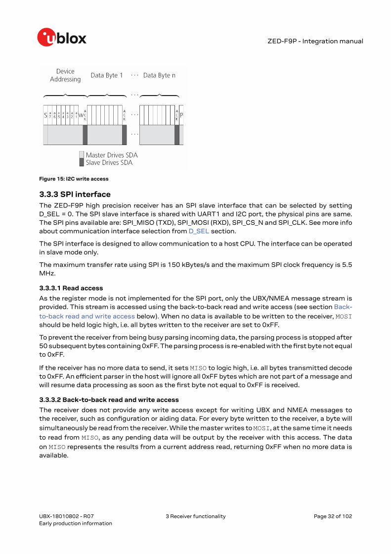
ZED-F9P - Integration manual
Figure 15: I2C write access
3.3.3 SPI interfaceThe ZED-F9P high precision receiver has an SPI slave interface that can be selected by settingD_SEL = 0. The SPI slave interface is shared with UART1 and I2C port, the physical pins are same.The SPI pins available are: SPI_MISO (TXD), SPI_MOSI (RXD), SPI_CS_N and SPI_CLK. See more infoabout communication interface selection from D_SEL section.
The SPI interface is designed to allow communication to a host CPU. The interface can be operatedin slave mode only.
The maximum transfer rate using SPI is 150 kBytes/s and the maximum SPI clock frequency is 5.5MHz.
3.3.3.1 Read access
As the register mode is not implemented for the SPI port, only the UBX/NMEA message stream isprovided. This stream is accessed using the back-to-back read and write access (see section Back-
to-back read and write access below). When no data is available to be written to the receiver, MOSIshould be held logic high, i.e. all bytes written to the receiver are set to 0xFF.
To prevent the receiver from being busy parsing incoming data, the parsing process is stopped after50 subsequent bytes containing 0xFF. The parsing process is re-enabled with the first byte not equalto 0xFF.
If the receiver has no more data to send, it sets MISO to logic high, i.e. all bytes transmitted decodeto 0xFF. An efficient parser in the host will ignore all 0xFF bytes which are not part of a message andwill resume data processing as soon as the first byte not equal to 0xFF is received.
3.3.3.2 Back-to-back read and write access
The receiver does not provide any write access except for writing UBX and NMEA messages tothe receiver, such as configuration or aiding data. For every byte written to the receiver, a byte will
simultaneously be read from the receiver. While the master writes to MOSI, at the same time it needs
to read from MISO, as any pending data will be output by the receiver with this access. The data
on MISO represents the results from a current address read, returning 0xFF when no more data isavailable.
UBX-18010802 - R07
3 Receiver functionality Page 32 of 102Early production information

ZED-F9P - Integration manual
Figure 16: SPI back-to-back read/write access
3.3.4 USB interfaceA single USB port is provided for host communication purposes.
The USB interface is compatible with a USB version 2.0 FS (full speed, 12 Mb/s) interface.
The ZED-F9P receiver supports only self-powered mode operation in which the receiver is suppliedfrom its own power supply. The V_USB pin is used to detect the availability of the USB port, i.e.whether the receiver is connected to a USB host.
USB suspend mode is not supported.
USB bus-powered mode is not supported.
It is important to connect V_USB to ground and leave data lines open when the USBinterface is not used in an application.
The voltage range for V_USB is specified from 3.0 V to 3.6 V, which differs slightly from thespecification for VCC.
The boot screen is retransmitted on the USB port after enumeration. However, messagesgenerated between boot-up of the receiver and USB enumeration are not visible on the USBport.
There are additional hardware requirements if USB is used:
• Pin 38, V_USB needs to be powered by a separate LDO enabled by module VCC and supplied bythe USB host.
• A pull down resistor is required on the output of this V_USB LDO• V_USB (pin 38) requires 1 uF capacitor mounted adjacent to the pin to ensure correct V_USB
voltage detection• Apply USB_DM and USB_DP series resistors; typically 27 Ω
Figure 17: ZED-F9P example circuit for USB interface
UBX-18010802 - R07
3 Receiver functionality Page 33 of 102Early production information
ZED-F9P - Integration manual
R11 = 100 k Ω is recommended
R4, R5 = 27 Ω is recommended
3.4 Predefined PIOsIn addition to the communication ports, there are some predefined PIOs provided by ZED-F9P tointeract with the receiver. These PIOs are described in this chapter.
3.4.1 D_SELThe D_SEL pin can be used to configure the functionality of pins 42 to 45 . It is possible to configurethe pins as UART1 + I2C, or as SPI. SPI is not available unless D_SEL pin is set to low. See Table 16below.
Pin No D_SEL == 0 D_SEL == 1
42 SPI_MISO UART1 TXD
43 SPI_MOSI UART1 RXD
44 SPI_CS_N I2C SDA
45 SPI_CLK I2C SCL
Table 16: D_SEL configuration
3.4.2 RESET_NThe ZED-F9P provides the ability to reset the receiver. The RESET_N pin is an input-only pin with aninternal pull-up resistor. Driving RESET_N low for at least 100 ms will trigger a cold start.
The RESET_N pin will delete all information and trigger a cold start. It should only be usedas a recovery option.
3.4.3 SAFEBOOT_NThe ZED-F9P provides a SAFEBOOT_N pin that is used to command the receiver safe boot mode.
If this pin is low at power up, the receiver starts in safe boot mode and GNSS operation is disabled.
The safe boot mode can be used to recover from situations where the flash content has becomecorrupted and needs to be restored.
In safe boot mode the receiver runs from a passive oscillator circuit with less accurate timing andhence the receiver is unable to communicate via USB.
In this mode only UART1 and I2C communication is possible. For communication via UART1 in safeboot mode, the host must send a training sequence (0 x 55 55 at 9600 baud) to the receiver in orderto begin communication. After this the host must wait at least 2 ms before sending any data.
It is recommended to have the possibility to pull the SAFEBOOT_N pin low in the application. Thiscan be provided using an externally connected test point or a host I/O port.
3.4.4 TIMEPULSEThe ZED-F9P high precision receiver provides a time pulse on the TIMEPULSE pin.
Shared TIMEPULSE2 and SAFEBOOT_N signals should be implemented maintaining thepossibility to pull the SAFEBOOT_N pin low in the application.
UBX-18010802 - R07
3 Receiver functionality Page 34 of 102Early production information

ZED-F9P - Integration manual
More information about the Timepulse feature, its possibility's and configuration can befound in the chapter Time pulse
3.4.5 TX_READYThis feature enables each port to define a corresponding pin, which indicates if bytes are ready to betransmitted. A listener can wait on the TX-READY signal instead of polling the I2C or SPI interfaces.The CFG-TXREADY message lets you configure the polarity and the number of bytes in the bufferbefore the TX-READY signal goes active. By default, this feature is disabled. For USB, this featureis configurable but might not behave as described below due to a different internal transmissionmechanism. If the number of pending bytes reaches the threshold configured for this port, thecorresponding pin will become active (configurable active-low or active-high), and stay active untilthe last bytes have been transferred from software to hardware.
This is not necessarily equal to all bytes transmitted, i.e. after the pin has become inactive,up to 16 bytes might still need to be transferred to the host.
The TX_READY pin can be selected from all PIOs which are not in use (see UBX-MON-HW3 in theZED-F9P Interface Description [2] for a list of the PIOs and their mapping). Each TX_READY pin isexclusively associated to one port and cannot be shared. If PIO is invalid or already in use, only theconfiguration for the specific TX_READY pin is ignored, the rest of the port configuration is appliedif valid. The acknowledge message does not indicate if the TX-READY configuration is successfullyset, it only indicates the successful configuration of the port. To validate successful configurationof the TX_READY pin, the port configuration should be read back and the settings of TX-READYfeature verified (will be set to disabled/all zero if the settings are invalid).
The threshold when TX_READY is asserted should not be set above 2 kB as it is possible that theinternal message buffer limit is reached before this. This results in the TX_READY pin never beingset as the messages are discarded before the threshold is reached.
3.4.5.1 Extended TX timeout
If the host does not communicate over SPI or I2C for more than approximately 2 seconds, the deviceassumes that the host is no longer using this interface and no more packets are scheduled forthis port. This mechanism can be changed by enabling "extended TX timeouts", in which case thereceiver delays idling the port until the allocated and undelivered bytes for this port reach 4 kB. Thisfeature is especially useful when using the TX-READY feature with a message output rate of lessthan once per second, and polling data only when data is available, determined by the TX_READYpin becoming active.
3.4.6 EXTINTEXTINT is an external interrupt pin with fixed input voltage thresholds with respect to VCC. It canbe used for functions such as accurate external frequency aiding and on/off control. Leave open ifunused, this function is disabled by default.
3.4.7 GEOFENCE_STAT interfaceThe ZED-F9P provides a GEOFENCE_STAT pin that indicates the current geofence status as towhether the receiver is inside any of the active areas.
This feature can be used for example to wake up a sleeping host when a defined geofence conditionis reached. It is possible to configure up to four circular areas as geofence locations. Once configured,the receiver continuously compares its current position with the preset geofenced areas.
For more information in this functionality, see Geofence state evaluation.
UBX-18010802 - R07
3 Receiver functionality Page 35 of 102Early production information

ZED-F9P - Integration manual
The receiver toggles the assigned pin according to the combined geofence state.
There are three possible outcomes for each geofence:
• Inside - The position is inside the geofence with the configured confidence level• Outside - The position lies outside of the geofence with the configured confidence level• Unknown - There is no valid position solution or the position uncertainty does not allow for
unambiguous state evaluation
The GEOFENCE_STAT pin is always set to high level when the combine geofence state is unknown.The low level can either represent the inside state or the outside state according to the value set inthe CFG-GEOFENCE-PINPOL configuration item. If the receiver is in software backup or in a reset,the pin will go to high accordingly.
The CFG-GEOFENCE-PIN configuration item refers to a PIO and not a physical device pin.The PIO number must be set so that it is mapped to the assigned geofence state device pin.The ZED-F9P high precision receiver is assigned PIO3 that is assigned to module pin 19.
3.4.8 RTK_STAT interfaceThe ZED-F9P provides an RTK_STAT pin that provides an indication of the RTK positioning status.It can be used to confirm if a valid stream of RTCM messages is being received. As valid RTCMmessages we only consider the RTCM messages that are supported and used by the receiver.
In general, the RTK_STAT level can be interpreted as follows: Alternating (blinking) pin level,indicates that a valid stream of RTCM messages is being received and utilized but no RTK fixedmode has been achieved. An active low pin level indicates that RTK fixed mode has been achieved.Otherwise, the pin level is high.
The RTK_STAT pin status can be mapped to the carrSoln field of the UBX-NAV-PVT andinterpreted as follows:
• An active low pin level indicates that RTK fixed mode has been achieved• Alternating (blinking) pin level, indicates that a valid stream of RTCM messages is being
received and utilized but no RTK fixed mode has been achieved• An active high pin level indicates that no carrier phase solution is available
3.5 Antenna supervisorAn active antenna supervisor provides the means to check the antenna for open and short circuitsand to shut off the antenna supply if a short circuit is detected. Once enabled, the active antennasupervisor produces status messages, reporting in NMEA and/or UBX protocol.
The antenna supervisor can be configured through the CFG-HW-ANT_* configuration items. Thecurrent configuration of the active antenna supervisor can also be checked by polling the relatedCFG-HW_ANT_* configuration items.
The current active antenna status can be determined by polling the UBX-MON-RF message. If anantenna is connected, the initial state after power-up is “Active Antenna OK" in the UBX-MON-RFmessage in the u-center "Message View".
An active antenna supervisor circuit is connected to the ANT_DET, ANT_OFF, ANT_SHORT_Npins. For an example the open circuit detection circuit using ANT_DET, "high" = Antenna detected(antenna consumes current); "low" = Antenna not detected (no current drawn).
The following schematic details the required circuit and the sections following it explain how toenable and monitor each feature:
UBX-18010802 - R07
3 Receiver functionality Page 36 of 102Early production information
ZED-F9P - Integration manual
Figure 18: ZED-F9P antenna supervisor
The bias-t inductor must be chosen for multi-band operation; a value of 120 nH 5% isrequired for our recommended Murata part if the current is limited below its 110 mA rating.See Antenna bias section for additional information.
Circuit shows buffer [U4]. Buffer is not strictly necessary when supplied from VCC. It is onlyrequired when supplying antenna voltage that is not obtained from or controlled by moduleVCC or VCC_RF .
Part Recommendation Comment
L1 300mA and >500 Ω at L-band frequencies
C2 MURATA GRM033R71C103KE14 CAP CER X7R 0402 10N 10% 16V
TYCO, 0.25PF, PESD0402-140 -55/+125C ESD protection diode on RF trace
Table 17: Recommended components for antenna supervisor
3.5.1 Antenna voltage control - ANT_OFFAntenna status (as reported in UBX-MON-RF and UBX-INF-NOTICE messages) is notreported unless the antenna voltage control has been enabled.
Enable the antenna voltage control by setting the configuration item CFG-HW-ANT_CFG_VOLTCTRL to true (1).
Result:
• UBX-MON-RF in u-center "Message View": Antenna status = OK. Antenna power status = ON• ANT_OFF pin = active high to turn antenna off therefore the pin is low to enable an external
antenna.
Start-up message at power up if configuration stored:
$GNTXT,01,01,02,ANTSUPERV=AC *00
$GNTXT,01,01,02,ANTSTATUS=INIT*3B
UBX-18010802 - R07
3 Receiver functionality Page 37 of 102Early production information
ZED-F9P - Integration manual
$GNTXT,01,01,02,ANTSTATUS=OK*25
ANTSUPERV=AC indicates antenna control is activated
3.5.2 Antenna short detection - ANT_SHORT_NEnable the antenna short detection by setting the configuration item CFG-HW-ANT_CFG_SHORTDET to true (1).
Result:
• UBX-MON-RF in u-center "Message View": Antenna status = OK. Antenna power status = ON• ANT_OFF = active high to disable an external antenna therefore the pin is low to enable an
external antenna.• ANT_SHORT_N = active low to detect a short therefore the pin is high (PIO pull up enabled to be
pulled low if shorted)
Start-up message at power up if configuration is stored:
$GNTXT,01,01,02,ANTSUPERV=AC SD *37
$GNTXT,01,01,02,ANTSTATUS=INIT*3B
$GNTXT,01,01,02,ANTSTATUS=OK*25
ANTSUPERV=AC SD (Antenna control and short detection activated)
Then if shorted (ANT_SHORT_N pulled low):
• UBX-MON-RF in u-center "Message View": Antenna status = SHORT. Antenna power status =ON (Antenna power control power down when short has not been enabled = off by default).
$GNTXT,01,01,02,ANTSTATUS=SHORT*73
• ANT_OFF = active high therefore still low (still enabled as auto power down is not enabled)
After a detected antenna short, the reported antenna status will keep on being reported asshorted. If the antenna short detection auto recovery is enabled, then the antenna statuscan recover after a timeout. To recover the antenna status immediately, a power cycle isrequired or configuring the antenna short detection functionality off and on.
3.5.3 Antenna short detection auto recoveryEnable the antenna short detection auto recovery by setting the configuration item CFG-HW-ANT_CFG_RECOVER to true (1).
Result:
• UBX-MON-RF in u-center "Message View": Antenna status = OK. Antenna power status = ON• ANT_OFF = active high there for the PIO is low to enable an external antenna• ANT_SHORT_N = high (PIO pull up enabled to be pulled low if shorted)
Start-up message at power up if configuration is stored:
$GNTXT,01,01,02,ANTSUPERV=AC SD PDoS SR*3E
$GNTXT,01,01,02,ANTSTATUS=INIT*3B
$GNTXT,01,01,02,ANTSTATUS=OK*25
ANTSUPERV=AC SD PDoS SR (indicates short circuit recovery added - SR)
UBX-18010802 - R07
3 Receiver functionality Page 38 of 102Early production information

ZED-F9P - Integration manual
Then if antenna is shorted (ANT_SHORT_N pulled low):
• $GNTXT,01,01,02,ANTSTATUS=SHORT*73
• UBX-MON-RF in u-center "Message View": Antenna status = SHORT. Antenna power status =OFF
• ANT_OFF = high (to disable - active high)
After a time out period receiver will re-test the short condition by enabling ANT_OFF = LOW
If a short is not present it will report antenna condition is OK:
$GNTXT,01,01,02,ANTSTATUS=OK*25
UBX-MON-RF in u-center "Message View": Antenna status = OK. Antenna power status = ON
3.5.4 Antenna open circuit detection - ANT_DETECTEnable the antenna open circuit detection by setting the configuration item CFG-HW-ANT_CFG_OPENDET to true (1).
Result:
• UBX-MON-RF in u-center "Message View": Antenna status = OK. Antenna power status = ON• ANT_OFF = active high therefore PIO is low to enable external antenna• ANT_SHORT_N = active low therefore PIO is high (PIO pull up enabled to be pulled low if
shorted)• ANT_DETECT = active high therefore PIO is high (PIO pull up enabled to be pulled low if antenna
not detected)
Start-up message at power up if configuration is stored:
$GNTXT,01,01,02,ANTSUPERV=AC SD OD PDoS SR*15
$GNTXT,01,01,02,ANTSTATUS=INIT*3B
$GNTXT,01,01,02,ANTSTATUS=OK*25
ANTSUPERV=AC SD OD PDoS SR (indicates open circuit detection added - OD)
Then if ANT_DETECT is pulled low to indicate no antenna:
$GNTXT,01,01,02,ANTSTATUS=OPEN*35
Then if ANT_DETECT is left floating or it is pulled high to indicate antenna connected:
$GNTXT,01,01,02,ANTSTATUS=OK*25
3.6 Multiple GNSS assistance (MGA)The u-blox MGA services provide a proprietary implementation of an A-GNSS protocol compatiblewith u-blox GNSS receivers. When a client device makes an MGA request, the service respondswith the requested data using UBX protocol messages. These messages are ready for directtransmission to the receiver communication port without requiring any modification by the MGAclient.
Currently, these MGA services consist of AssistNow Online and Offline, each delivered by the HTTPor HTTPS protocols.
AssistNow Online optionally provides satellite ephemerides, health information and time aiding datasuitable for GNSS receiver systems with direct internet access.
UBX-18010802 - R07
3 Receiver functionality Page 39 of 102Early production information
ZED-F9P - Integration manual
The AssistNow Offline service benefits u-blox GNSS receivers that only have occasional internetaccess. Users request data from the service by specifying the time period for which they wantcoverage (1 to 5 weeks).
The data downloaded from the service is organized by date and encoded into a sequence of UBXMGA messages.
The ZED-F9P supports AssistNow Online only.
3.6.1 AuthorizationThe AssistNow Online Service is only available for use by u-blox customers. In order to use theservices, customers will need to obtain an authorization token from u-blox. This token must besupplied as a parameter whenever a request is made to either service. Please contact your localtechnical support or go to https://www.u-blox.com/en/solution/services/assistnow to get moreinformation and request an authorization token.
3.6.2 Multiple serversThe implementation of the AssistNow Online Service is designed to be highly available and reliable.Nonetheless, there will be rare occasions when a server is not available (e.g. due to failure or someform of maintenance activity). In order to protect customers against the impact of such outages,u-blox runs at least two instances of the AssistNow Online Service on independent machines.Customers have a choice of requesting assistance data from any of these servers, as all will providethe same information. However, should one fail for whatever reason, it is highly unlikely that theother server(s) will also be unavailable. Therefore customers requiring the best possible availabilityare recommended to implement a scheme where they direct their requests to a chosen server, but,if that server fails to respond, have a fallback mechanism to use another server instead.
3.6.3 Preserving information during power-offThe performance of u-blox receivers immediately after they are turned on is enhanced by providingthem with as much useful information as possible. AssistNow services are one way to achieve this,but retaining information from previous use of the receiver can be just as valuable. All the types ofdata delivered by assistance can be retained while the receiver is powered down for use when poweris restored. Obviously the value of this data will diminish as time passes, but in many cases it remainsvery useful and can significantly improve time to first fix.
There are several ways in which a u-blox receiver can retain useful data while it is powered down,including:
• Battery-backed RAM: The receiver can be supplied with sufficient power to maintain a smallportion of internal storage, while it is otherwise turned off. This is the best mechanism,provided that the small amount of electrical power required can be supplied continuously.V_BCKP is the pin to sustain battery-backed RAM.
• Save-on-Shutdown: The receiver can be instructed to dump its current state to flash memoryas part of the shutdown procedure; this data is then automatically retrieved when the receiveris restarted. For more information, see the description of the UBX-UPD-SOS messages in theZED-F9P Interface description [2].
3.6.4 AssistNow OnlineAssistNow Online is u-blox's end-to-end Assisted GNSS (A-GNSS) solution for receivers that haveaccess to the internet. Data supplied by the AssistNow Online Service can be directly uploaded toa u-blox receiver in order to substantially reduce time to first fix (TTFF), even under poor signalconditions (typically around 2 seconds; see ZED-F9P Data sheet [1] "Aided start"). The system
UBX-18010802 - R07
3 Receiver functionality Page 40 of 102Early production information

ZED-F9P - Integration manual
works by collecting data such as ephemeris and almanac from the satellites through u-blox's "GlobalReference Network" of receivers and providing this data to customers in a convenient form that canbe forwarded directly to u-blox receivers.
The AssistNow Online Service uses a simple, stateless, HTTP interface. Therefore, it works on allstandard mobile communication networks that support internet access, including GPRS, UMTS andWireless LAN. No special arrangements need to be made with mobile network operators to enableAssistNow Online.
Figure 19: MGA architecture
The data returned by the AssistNow Online Service is a sequence of UBX-MGA messages, startingwith an estimate of the current time in the form of a UBX-MGA-INI-TIME_UTC message.
AssistNow Online currently supports GPS, GLONASS, BeiDou, Galileo, and QZSS.
Customers may choose to use third party sources of assistance data instead of usingthe AssistNow Online Service. Customers choosing this option will need to ensure thatthe data is converted from the format used by the third party source to the appropriateMGA messages. However, it is important to ensure that the receiver has an estimate of thecurrent time before it processes any other assistance data. For this reason, it is stronglyrecommended to send a UBX-MGA-INITIME_UTC or UBX-MGA-INI-TIME_GNSS as the firstmessage of any assistance.
3.6.4.1 Host software
As u-blox receivers have no means to connect directly with the internet, the AssistNow Onlinesystem can only work if the host system that contains the receiver can connect to the internet,download the data from the AssistNow Online Service and forward it on to the receiver. In thesimplest case that may involve fetching the data from the AssistNow Online Service (by means of asingle HTTP or HTTPS GET request), and sending the resulting data to the receiver.
Depending on the circumstances, it may be beneficial for the host software to include:
• Creating an appropriate UBX-MGA-INI-TIME_UTC message to deliver a better estimation ofthe current time to the receiver, especially if the host system has a very good estimation of thecurrent time and can deliver a time pulse to one of the receiver's EXTINT pins.
• Enabling and using flow control to prevent loss of data due to buffer overflow in the receiver.
UBX-18010802 - R07
3 Receiver functionality Page 41 of 102Early production information
ZED-F9P - Integration manual
u-blox provides the source code for an example library, called libMGA, that provides all of thefunctionality we expect in most host software.
3.6.4.2 AssistNow Online sequence
A typical sequence of use of the AssistNow Online Service comprises the following steps:
• Power up the u-blox receiver.• Request data from the AssistNow Online Service.• Optionally send UBX-MGA-INI-TIME_UTC followed by hardware time synchronization pulse.• Send the UBX messages obtained from the AssistNow Online Service to the receiver.
3.6.4.3 Flow control
u-blox receivers aim to process incoming messages as quickly as possible, but there will always bea small delay in processing each message. Uploading assistance data to the receiver can involvesending as many as one hundred individual messages to the receiver, one after the other. If thecommunication link is fast, and/or the receiver is busy (trying to acquire new signals), it is possiblethat the internal buffers will overflow and some messages will be lost. In order to combat this, u-bloxreceivers support an optional flow control mechanism for assistance.
Flow control is activated by setting the CFG-NAVSPG-ACKAIDING configuration item. As a resultthe receiver will issue an acknowledgment message (UBX-ACK-ACK) for each assistance messageit successfully receives. The host software can examine these acknowledgments to establishwhether there were any problems with the data sent to the receiver and deduce (by the lack ofacknowledgment) if any messages have been lost. It may then be appropriate to resend some of theassistance messages.
The simplest way to implement flow control would be to send one UBX-MGA message at a time,waiting for the acknowledgment, before sending the next. However, such a strategy is likely tointroduce significant delays into the whole assistance process. The best strategy will depend on theamount of assistance data being sent and the nature of the communications link (e.g. baud rate ofserial link). u-blox recommends that when customers are developing their host software they startby sending all assistance messages and then analyze the resulting acknowledgments to see if anymessages have been lost. Adding small delays during the transmission may be a simple but effectiveway to avoid loss of data.
3.6.4.4 Service parameters
The information exchange with the AssistNow Online Service is based on the HTTP protocol. Theu-blox MGA service supports encrypted HTTPS communication. Upon reception of an HTTP GETrequest, the server will respond with the required messages in binary format or with an error stringin text format. After delivery of all data, the server will terminate the connection.
The HTTP GET request from the client to the server should contain a standard HTTP query string inthe request URL. The query string consists of a set of "key=value" parameters in the following form:
key=value;key=value;key=value;
The following rules apply:
• The order of keys is important.• Keys and values are case-sensitive.• Keys and values must be separated by an "equal" character ("=").• Key/value pairs must be separated by semicolons (";").• If a value contains a list, each item in the list must be separated by a comma (",").
The following table describes the keys that are supported:
UBX-18010802 - R07
3 Receiver functionality Page 42 of 102Early production information

ZED-F9P - Integration manual
Key name Unit/range Optional Description
token String Mandatory The authorization token supplied by u-blox when a client registers to use theservice.
gnss String Mandatory A comma-separated list of the GNSS for which data should be returned. Valid GNSSare: gps, gal, glo, bds and qzss (case-sensitive).
datatype String Mandatory A comma-separated list of the data types required by the client. Valid data typesare: eph, alm, aux and pos. Time data is always returned for each request. If thevalue of this parameter is an empty string, only time data will be returned.
lat Numeric[degrees]
Optional Approximate user latitude in WGS 84 expressed in degrees and fractional degrees.Must be in range -90 to 90. Example: lat=47.2.
lon Numeric[degrees]
Optional Approximate user longitude in WGS 84 expressed in degrees and fractionaldegrees. Must be in range -180 to 180. Example: lon=8.55.
alt Numeric[meters]
Optional Approximate user altitude above WGS 84 Ellipsoid. If this value is not provided, theserver assumes an altitude of 0 meters. Must be in range -1000 to 50000.
pacc Numeric[meters]
Optional Approximate accuracy of submitted position (see the Position parameters (lat, lon,alt and pacc) section below). If this value is not provided, the server assumes anaccuracy of 300 km. Must be in range 0 to 6000000.
tacc Numeric[seconds]
Optional The timing accuracy (see the Time parameters (tacc and latency) section below). Ifthis value is not provided, the server assumes an accuracy of 10 seconds. Must bein range 0 to 3600.
latency Numeric[seconds]
Optional Typical latency between the time the server receives the request, and the timewhen the assistance data arrives at the u-blox receiver. The server can use thisvalue to correct the time being transmitted to the client. If this value is notprovided, the server assumes a latency of 0. Must be in range 0 to 3600.
filteronpos (no valuerequired)
Optional If present, the ephemeris data returned to the client will only contain data for thesatellites which are likely to be visible from the approximate position provided bythe lat, lon, alt and pacc parameters. If the lat and lon parameters are not providedthe service will return an error.
filteronsv String Optional A comma-separated list of u-blox gnssId:svId pairs. The ephemeris data returned tothe client will only contain data for the listed satellites.
Table 18: AssistNow Online parameter keys
Thus, as an example, a valid parameter string would be:
token=XXXXXXXXXXXXXXXXXXXXXX;gnss=gps,qzss;datatype=eph,pos,aux;lat=47.28;lon=8.56;pacc=1000
3.6.4.4.1 Position parameters (lat, lon, alt and pacc)The position parameters (lat, lon, alt and pacc) are used by the server for two purposes:
• If the filteronpos parameter is provided, the server determines the currently visible satellites atthe user position, and only sends the ephemeris data of those satellites which should be in viewat the location of the user. This reduces bandwidth requirements. In this case the "pacc" valueis taken into account, meaning that the server will return all SVs visible in the given uncertaintyregion.
• If the datatype "pos" is requested, the server will return the position and accuracy in theresponse data. When this data is supplied to the u-blox receiver, depending on the accuracyof the provided data, the receiver can then choose to select a better startup strategy. Forexample, if the position is accurate to 100 km or better, the u-blox receiver will choose to gofor a more optimistic startup strategy. This will result in quicker startup time. The receiver willdecide which strategy to choose, depending on the "pacc" parameter. If the submitted userposition is less accurate than what is being specified with the "pacc" parameter, then the userwill experience prolonged or even failed startups.
3.6.4.4.2 Time parameters (tacc and latency)Time data is always returned with each request. The time data refers to the time at which theresponse leaves the server, corrected by an optional latency value. This time data provided by theservice is accurate to approximately 10 ms but by default the time accuracy is indicated to be +/-10
UBX-18010802 - R07
3 Receiver functionality Page 43 of 102Early production information

ZED-F9P - Integration manual
seconds in order to account for network latency and any time between the client receiving the dataand it being provided to the receiver.
If both the network latency and the client latency can safely be assumed to be very low (or areknown), the client can choose to set the accuracy of the time message (tacc) to a much smaller value(e.g. 0.5 s). This will result in a faster TTFF. The latency can also be adjusted as needed. However,these fields should be used with caution: if the time accuracy is not correct when the time datareaches the receiver, the receiver may experience prolonged or even failed startups.
For optimal results, the client should establish an accurate sense of time itself (e.g. by calibratingits system clock using a local NTP service) and then modify the time data received from the serviceas appropriate.
3.7 Clocks and timeThis section introduces and explains the concepts of receiver clocks and time bases.
3.7.1 Receiver local timeThe receiver is dependent on a local oscillator for both the operation of its radio parts and also fortiming within its signal processing. No matter what nominal frequency the local oscillator has, u-bloxreceivers subdivide the oscillator signal to provide a 1 kHz reference clock signal, which is used todrive many of the receiver's processes. In particular, the measurement of satellite signals is arrangedto be synchronized with the "ticking" of this 1 kHz clock signal.
When the receiver first starts, it has no information about how these clock ticks relate to other timesystems; it can only count time in 1 millisecond steps. However, as the receiver derives informationfrom the satellites it is tracking or from aiding messages, it estimates the time that each 1 kHzclock tick takes in the time-base of one of the GNSS systems in a multi-GNSS receiver. In previousgenerations of u-blox receivers this was always the GPS time-base, but for the current generationit could be GPS, GLONASS, Galileo, or BeiDou. This estimate of GNSS time based on the local 1 kHzclock is called receiver local time.
As receiver local time is a mapping of the local 1 kHz reference onto a GNSS time-base, itmay experience occasional discontinuities, especially when the receiver first starts up and theinformation it has about the time-base is changing. Indeed, after a cold start, the receiver localtime will initially indicate the length of time that the receiver has been running. However, when thereceiver obtains some credible timing information from a satellite or an aiding message, it will jumpto an estimate of GNSS time.
3.7.2 Navigation epochsEach navigation solution is triggered by the tick of the 1 kHz clock nearest to the desired navigationsolution time. This tick is referred to as a navigation epoch. If the navigation solution attempt issuccessful, one of the results is an accurate measurement of time in the time-base of the chosenGNSS system, called GNSS system time. The difference between the calculated GNSS system timeand receiver local time is called the clock bias (and the clock drift is the rate at which this bias ischanging).
In practice the receiver's local oscillator will not be as stable as the atomic clocks to which GNSSsystems are referenced and consequently clock bias will tend to accumulate. However, whenselecting the next navigation epoch, the receiver will always try to use the 1 kHz clock tick which itestimates to be closest to the desired fix period as measured in GNSS system time. Consequentlythe number of 1 kHz clock ticks between fixes will occasionally vary. This means that when producing
UBX-18010802 - R07
3 Receiver functionality Page 44 of 102Early production information
ZED-F9P - Integration manual
one fix per second, there will normally be 1000 clock ticks between fixes, but sometimes, to correctdrift away from GNSS system time, there will be 999 or 1001.
The GNSS system time calculated in the navigation solution is always converted to a time in boththe GPS and UTC time-bases for output.
Clearly when the receiver has chosen to use the GPS time-base for its GNSS system time, conversionto GPS time requires no work at all, but conversion to UTC requires knowledge of the number ofleap seconds since GPS time started (and other minor correction terms). The relevant GPS-to-UTCconversion parameters are transmitted periodically (every 12.5 minutes) by GPS satellites, but canalso be supplied to the receiver via the UBX-MGA-GPS-UTC aiding message. By contrast when thereceiver has chosen to use the GLONASS time-base as its GNSS system time, conversion to GPStime is more difficult as it requires knowledge of the difference between the two time-bases, but asGLONASS time is closely linked to UTC, conversion to UTC is easier.
When insufficient information is available for the receiver to perform any of these time-baseconversions precisely, pre-defined default offsets are used. Consequently plausible times are nearlyalways generated, but they may be wrong by a few seconds (especially shortly after receiver start).Depending on the configuration of the receiver, such "invalid" times may well be output, but withflags indicating their state (e.g. the "valid" flags in UBX-NAV-PVT).
u-blox receivers employ multiple GNSS system times and/or receiver local times (in orderto support multiple GNSS systems concurrently), so users should not use UBX messagesreporting GNSS system time or receiver local time. It is recommended to use messages thatreport UTC time and other messages are retained only for backwards compatibility reasons.
3.7.3 iTOW timestampsAll the main UBX-NAV messages (and some other messages) contain an iTOW field which indicatesthe GPS time at which the navigation epoch occurred. Messages with the same iTOW value can beassumed to have come from the same navigation solution.
Note that iTOW values may not be valid (i.e. they may have been generated with insufficientconversion data) and therefore it is not recommended to use the iTOW field for any other purpose.
The original designers of GPS chose to express time/date as an integer week number(starting with the first full week in January 1980) and a time of week (often abbreviatedto TOW) expressed in seconds. Manipulating time/date in this form is far easier for digitalsystems than the more conventional year/month/day, hour/minute/second representation.Consequently, most GNSS receivers use this representation internally, only converting to amore conventional form at external interfaces. The iTOW field is the most obvious externallyvisible consequence of this internal representation.
If reliable absolute time information is required, users are recommended to use the UBX-NAV-PVTnavigation solution message which also contains additional fields that indicate the validity (andaccuracy in UBX-NAV-PVT) of the calculated times (see also the GNSS times section below forfurther messages containing time information).
3.7.4 GNSS timesEach GNSS has its own time reference for which detailed and reliable information is provided in themessages listed in the table below.
Time reference Message
GPS time UBX-NAV-TIMEGPS
BeiDou time UBX-NAV-TIMEBDS
UBX-18010802 - R07
3 Receiver functionality Page 45 of 102Early production information

ZED-F9P - Integration manual
Time reference Message
GLONASS time UBX-NAV-TIMEGLO
Galileo time UBX-NAV-TIMEGAL
UTC time UBX-NAV-TIMEUTC
Table 19: GNSS times
3.7.5 Time validityInformation about the validity of the time solution is given in the following form:
• Time validity: Information about time validity is provided in the valid flags (e.g. validDateand validTime flags in the UBX-NAV-PVT message). If these flags are set, the time is knownand considered valid for use. These flags are shown in table GNSS times in section GNSS timesabove as well as in the UBX-NAV-PVT message.
• Time validity confirmation: Information about confirmed validity is provided in theconfirmedDate and confirmedTime flags in the UBX-NAV-PVT message. If these flags areset, the time validity can be confirmed by using an additional independent source, meaningthat the probability of the time to be correct is very high. Note that information about timevalidity confirmation is only available if the confirmedAvai bit in the UBX-NAV-PVT messageis set.
validDate means that the receiver has knowledge of the current date. However, it mustbe noted that this date might be wrong for various reasons. Only when the confirmedDateflag is set, the probability of the incorrect date information drops significantly.
validTime means that the receiver has knowledge of the current time. However, it mustbe noted that this time might be wrong for various reasons. Only when the confirmedTimeflag is set, the probability of incorrect time information drops significantly.
fullyResolved means that the UTC time is known without full seconds ambiguity. Whenderiving UTC time from GNSS time the number of leap seconds must be known, with theexception of GLONASS. It might take several minutes to obtain such information from theGNSS payload. When the one second ambiguity has not been resolved, the time accuracy isusually in the range of ~20s.
3.7.6 UTC representationUTC time is used in many NMEA and UBX messages. In NMEA messages it is always reportedrounded to the nearest hundredth of a second. Consequently, it is normally reported withtwo decimal places (e.g. 124923.52). Although compatibility mode (selected using CFG-NMEA-COMPAT) requires three decimal places, rounding to the nearest hundredth of a second remains, sothe extra digit is always 0.
UTC time is also reported within some UBX messages, such as UBX-NAV-TIMEUTC and UBX-NAV-PVT. In these messages date and time are separated into seven distinct integer fields. Six ofthese (year, month, day, hour, min and sec) have fairly obvious meanings and are all guaranteed tomatch the corresponding values in NMEA messages generated by the same navigation epoch. Thisfacilitates simple synchronization between associated UBX and NMEA messages.
The seventh field is called nano and it contains the number of nanoseconds by which the rest ofthe time and date fields need to be corrected to get the precise time. So, for example, the UTC time12:49:23.521 would be reported as: hour: 12, min: 49, sec: 23, nano: 521000000.
It is however important to note that the first six fields are the result of rounding to the nearesthundredth of a second. Consequently the nano value can range from -5000000 (i.e. -5 ms) to+994999999 (i.e. nearly 995 ms).
UBX-18010802 - R07
3 Receiver functionality Page 46 of 102Early production information
ZED-F9P - Integration manual
When the nano field is negative, the number of seconds (and maybe minutes, hours, days, monthsor even years) will have been rounded up. Therefore, some or all of them must be adjusted in orderto get the correct time and date. Thus in an extreme example, the UTC time 23:59:59.9993 on 31stDecember 2011 would be reported as: year: 2012, month: 1, day: 1, hour: 0, min: 0, sec: 0, nano:-700000.
Of course, if a resolution of one hundredth of a second is adequate, negative nano values can simplybe rounded up to 0 and effectively ignored.
Which master clock the UTC time is referenced to is output in the message UBX-NAV-TIMEUTC.
The preferred variant of UTC time can be specified using CFG-NAVSPG-UTCSTANDARDconfiguration item.
3.7.7 Leap secondsOccasionally it is decided (by one of the international time keeping bodies) that, due to the slightlyuneven spin rate of the Earth, UTC has moved sufficiently out of alignment with mean solar time (i.e.the Sun no longer appears directly overhead at 0 longitude at midday). A "leap second" is thereforeannounced to bring UTC back into close alignment. This normally involves adding an extra secondto the last minute of the year, but it can also happen on 30th June. When this happens UTC clocksare expected to go from 23:59:59 to 23:59:60 and only then on to 00:00:00.
It is also theoretically possible to have a negative leap second, in which case there will only be 59seconds in a minute and 23:59:58 will be followed by 00:00:00.
u-blox receivers are designed to handle leap seconds in their UTC output and consequently usersprocessing UTC times from either NMEA or UBX messages should be prepared to handle minutesthat are either 59 or 61 seconds long.
Leap second information can be polled from the u-blox receiver with the message UBX-NAV-TIMELS.
3.7.8 Real time clocku-blox receivers contain circuitry to support a real time clock, which (if correctly fitted and powered)keeps time while the receiver is otherwise powered off. When the receiver powers up, it attempts touse the real time clock to initialize receiver local time and in most cases this leads to appreciablyfaster first fixes.
3.7.9 DateAll GNSS frequently transmit information about the current time within their data message. In mostcases, this is a time of week (often abbreviated to TOW), which indicates the elapsed number ofseconds since the start of the week (midnight Saturday/Sunday). In order to map this to a full date,it is necessary to know the week and so the GNSS also transmit a week number, typically every 30seconds. Unfortunately the GPS L1C/A data message was designed in a way that only allows thebottom 10 bits of the week number to be transmitted. This is not sufficient to yield a completelyunambiguous date as every 1024 weeks (a bit less than 20 years), the transmitted week numbervalue "rolls over" back to zero. Consequently, GPS L1 receivers cannot tell the difference between,for example, 1980, 1999 or 2019 etc.
Fortunately, although BeiDou and Galileo have similar representations of time, they transmitsufficient bits for the week number to be unambiguous for the foreseeable future (the firstambiguity will be in 2078 for Galileo and not until 2163 for BeiDou). GLONASS has a differentstructure, based on a time of day, but again transmits sufficient information to avoid any ambiguityduring the expected lifetime of the system (the first ambiguous date will be in 2124). Therefore, u-
UBX-18010802 - R07
3 Receiver functionality Page 47 of 102Early production information
ZED-F9P - Integration manual
blox 9 receivers using Protocol Version 24 and above regard the date information transmitted byGLONASS, BeiDou and Galileo to be unambiguous and, where necessary, use this to resolve anyambiguity in the GPS date.
Customers attaching u-blox receivers to simulators should be aware that GPS time isreferenced to 6th January 1980, GLONASS to 1st January 1996, Galileo to 22nd August1999 and BeiDou to 1st January 2006; the receiver cannot be expected to work reliably withsignals simulated before these dates.
3.7.9.1 GPS-only date resolution
In circumstances where only GPS L1C/A signals are available and for receivers with earlier firmwareversions, the receiver establishes the date by assuming that all week numbers must be at leastas large as a reference rollover week number. This reference rollover week number is hard-codedat compile time and is normally set a few weeks before the software is completed, but it can beoverridden by CFG-NAVSPG-WKNROLLOVER configuration item to any value the user wishes.
The following example illustrates how this works: Assume that the reference rollover week numberset in the firmware at compile time is 1524 (which corresponds to a week in calendar year 2009,but would be transmitted by the satellites as 500). In this case, if the receiver sees transmissionscontaining week numbers in the range of 500 ... 1023, these will be interpreted as week numbers1524 ... 2047 (calendar year 2009 ... 2019), whereas transmissions with week numbers from 0 to499 are interpreted as week numbers 2048 ... 2547 (calendar year 2019 ... 2028).
It is important to set the reference rollover week number appropriately when supplying u-blox receivers with simulated signals, especially when the scenarios are in the past.
3.8 Timing functionalityIn addition to positioning and navigation applications, GNSS signals are widely used as low-costprecision time or frequency references used by remote or distributed wireless communication,industrial, financial, and power distribution equipment. By capitalizing on atomic clocks which areon-board positioning satellites, GNSS signals which contain embedded timing information canbe used to synchronize equipment, as well as to provide UTC time. For wireless communicationstandards that utilize Time Division Multiplex (TDM) and applications such as femtocell basestations, a precision time reference is mandatory.
3.8.1 Time pulse
3.8.1.1 Introduction
u-blox receivers include a time pulse function providing clock pulses with configurable duration andfrequency. The time pulse function can be configured using the CFG-TP-* configuration group. TheUBX-TIM-TP message provides time information for the next pulse and the time source.
UBX-18010802 - R07
3 Receiver functionality Page 48 of 102Early production information

ZED-F9P - Integration manual
Figure 20: Time pulse
3.8.1.2 Recommendations
• The time pulse can be aligned to a wide variety of GNSS times or to variants of UTC derivedfrom them (see the chapter on time bases). However, it is strongly recommended that thechoice of time base is aligned with the available GNSS signals (so to produce GPS time orUTC(USNO), ensure GPS signals are available, and for GLONASS time or UTC(SU) ensurethe presence GLONASS signals). This will involve coordinating the setting of CFG-SIGNAL-*configuration group with the choice of time pulse time base.
• When using time pulse for precision timing applications it is recommended to calibrate theantenna cable delay against a reference timing source.
• In order to get the best timing accuracy with the antenna, a fixed and accurate position isneeded.
• If relative time accuracy between multiple receivers is required, do not mix receivers of differentproduct families. If this is required, the receivers must be calibrated accordingly, by settingcable delay and user delay.
• The recommended configuration when using the UBX-TIM-TP message is to set both themeasurement rate (CFG-RATE-MEAS) and the time pulse frequency (CFG-TP-*) to 1 Hz.
Since the rate of UBX-TIM-TP is bound to 1 Hz, more than one UBX-TIM-TP message canappear between two pulses if the time pulse frequency is set larger than 1 Hz. In this caseall UBX-TIM-TP messages in between a time pulse T1 and T2 belong to T2 and the last UBX-TIM-TP before T2 reports the most accurate quantization error. In general, if the time pulserate is not configured to 1 Hz, there will not be a single UBX-TIM-TP message for each timepulse.
The sequential order of the signal present at the TIMEPULSE pin and the respective output messagefor the simple case of 1 pulse per second (1PPS) is shown in the following figure.
UBX-18010802 - R07
3 Receiver functionality Page 49 of 102Early production information

ZED-F9P - Integration manual
Figure 21: Time pulse and TIM-TP
3.8.1.3 GNSS time bases
GNSS receivers must handle a variety of different time bases as each GNSS has its own referencesystem time. What is more, although each GNSS provides a model for converting their system timeinto UTC, they all support a slightly different variant of UTC. So, for example, GPS supports a variantof UTC as defined by the US National Observatory, while BeiDou uses UTC from the National TimeService Center, China (NTSC). While the different UTC variants are normally closely aligned, theycan differ by as much as a few hundreds of nanoseconds.
Although u-blox receivers can combine a variety of different GNSS times internally, the user mustchoose a single type of GNSS time and, separately, a single type of UTC for input (on EXTINTs) andoutput (via the time pulse) and the parameters reported in corresponding messages.
The CFG-TP-* configuration group allows the user to choose between any of the supported GNSS(GPS, GLONASS, BeiDou, etc) times and UTC. Also, the CFG-NAVSPG-* configuration group allowsthe user to select which variant of UTC the receiver should use. This includes an "automatic"option which causes the receiver to select an appropriate UTC version itself, based on the GNSSconfiguration, using, in order of preference, USNO if GPS is enabled, SU if GLONASS is enabled, NTSCif BeiDou is enabled and, finally, European if Galileo is enabled.
The receiver will assume that the input time pulse uses the same GNSS time base as specified forthe output using CFG-TP-*. So if the user selects GLONASS time for time pulse output, any timepulse input must also be aligned to GLONASS time (or to the separately chosen variant of UTC).Where UTC is selected for time pulse output, any GNSS time pulse input will be assumed to bealigned to GPS time.
u-blox receivers allow users to independently choose GNSS signals used in the receiver(using CFG-SIGNAL-*) and the input/output time base (using CFG-TP-*). For example itis possible to instruct the receiver to use GPS and GLONASS satellite signals to generateBeiDou time. This practice will compromise time-pulse accuracy if the receiver cannotmeasure the timing difference between the constellations directly and is therefore notrecommended.
The information that allows GNSS times to be converted to the associated UTC times isonly transmitted by the GNSS at relatively infrequent periods. For example GPS transmitsUTC(USNO) information only once every 12.5 minutes. Therefore, if a time pulse isconfigured to use a variant of UTC time, after a cold start, substantial delays before thereceiver has sufficient information to start outputting the time pulse can be expected.
3.8.1.4 Time pulse configuration
u-blox ZED-F9P receivers provide a time pulse (TIMEPULSE) signal with a configurable pulse period,pulse length and polarity (rising or falling edge).
UBX-18010802 - R07
3 Receiver functionality Page 50 of 102Early production information

ZED-F9P - Integration manual
It is possible to define different signal behavior (i.e. output frequency and pulse length) dependingon whether or not the receiver is locked to a reliable time source. Time pulse signal can be configuredusing the configuration group CFG-TP-*.
3.8.1.5 Configuring time pulse with CFG-TP-*
The configuration group CFG-TP-* can be used to change the time pulse settings, and includes thefollowing parameters defining the pulse:
• timepulse enable - Time pulse is active if this item is set.• frequency/period type - Determines whether the time pulse is interpreted as frequency or
period.• length/ratio type - Determines whether the time pulse length is interpreted as length[us] or
pulse ratio[%].• antenna cable delay - Signal delay due to the cable between antenna and receiver.• pulse frequency/period - Frequency or period time of the pulse when locked mode is not
configured or active.• pulse frequency/period lock - Frequency or period time of the pulse, as soon as receiver has
calculated a valid time from a received signal. Only used if the corresponding item is set to useanother setting in locked mode.
• pulse length/ratio - Length or duty cycle of the generated pulse, either specifies a time or ratiofor the pulse to be on/off.
• pulse length/ratio lock - Length or duty cycle of the generated pulse, as soon as receiver hascalculated a valid time from a received signal. Only used if the corresponding item is set to useanother setting in locked mode.
• user delay - The cable delay from the receiver to the user device plus signal delay of any userapplication.
• lock to GNSS freq - Use frequency gained from GNSS signal information rather than localoscillator's frequency if item is set.
• locked other setting - If this item is set, as soon as the receiver can calculate a valid time, thealternative setting is used. This mode can be used for example to disable time pulse if time isnot locked, or indicate lock with different duty cycles.
• align to TOW - If this item is set, pulses are aligned to the top of a second.• polarity - If set, the first edge of the pulse is a rising edge (pulse polarity: rising).• grid UTC/GNSS - Selection between UTC (0), GPS (1), GLONASS (2) and BeiDou (3) timegrid.
Also affects the time output by UBX-TIM-TP message.
The maximum pulse length cannot exceed the pulse period.
Time pulse settings shall be chosen in such a way, that neither the high nor the low periodof the output is less than 50 ns (except when disabling it completely), otherwise pulses canbe lost.
3.8.1.5.1 ExampleThe example below shows the 1PPS TIMEPULSE signal generated on the time pulse outputaccording to the specific parameters of the CFG-TP-* configuration group:
• CFG-TP-TP1_ENA = 1• CFG-TP-PERIOD_TP1 = 100 000 µs• CFG-TP-LEN_TP1 = 100 000 µs• CFG-TP-TIMEGRID_TP1 = 1 (GPS)• CFG-TP-PULSE_LENGTH_DEF = 0 (Period)• CFG-TP-ALIGN_TO_TOW_TP1 = 1• CFG-TP-USE_LOCKED_TP1 = 1
UBX-18010802 - R07
3 Receiver functionality Page 51 of 102Early production information

ZED-F9P - Integration manual
• CFG-TP-POL_TP1 = 1• CFG-TP-PERIOD_LOCK_TP1 = 100 000 µs• CFG-TP-LEN_LOCK_TP1 = 100 000 µs
The 1 Hz output is maintained whether or not the receiver is locked to GPS time. The alignment toTOW can only be maintained when GPS time is locked.
Figure 22: Time pulse signal with the example parameters
3.8.2 TimemarkThe receiver can be used to provide an accurate measurement of the time at which a pulse wasdetected on the external interrupt pin. The reference time can be chosen by setting the time sourceparameter to UTC, GPS, GLONASS, BeiDou, Galileo or local time in the CFG-TP-* configuration group.The UTC standard can be set in the CFG-NAVSPG-* configuration group. The delay figures definedwith CFG-TP-* are also applied to the results output in the UBX-TIM-TM2 message.
A UBX-TIM-TM2 message is output at the next epoch if
• The UBX-TIM-TM2 message is enabled, or• A rising or falling edge was triggered since last epoch on one of the EXTINT channels.
The UBX-TIM-TM2 messages includes the time of the last timemark, new rising/falling edgeindicator, time source, validity, number of marks and a quantization error. The timemark is triggeredcontinuously.
Only the last rising and falling edge detected between two epochs is reported since theoutput rate of the UBX-TIM-TM2 message corresponds to the measurement rate configuredwith CFG-RATE-MEAS (see Figure 23 below).
UBX-18010802 - R07
3 Receiver functionality Page 52 of 102Early production information

ZED-F9P - Integration manual
Figure 23: Timemark
3.9 SecurityThe security concept of ZED-F9P covers the air interface between the receiver and the GNSSsatellites and the integrity of the receiver itself.
There are functions to monitor/detect certain security threads and report it to the host system.Other functions try to mitigate the thread and allow the receiver to operate normally.
The table below gives an overview about possible threads and which functionality is available todetect and/or mitigate it.
Threat u-blox solution
Over air signal integrity Spoofing detection/mitigation
Jamming detection/mitigation
GNSS receiver integrity Secure boot
Secure firmware update
Table 20: u-blox security options
3.9.1 Spoofing detection / monitoringSpoofing is the process whereby someone tries to forge a GNSS signal with the intention of foolingthe receiver into calculating a different user position than the true one.
UBX-18010802 - R07
3 Receiver functionality Page 53 of 102Early production information
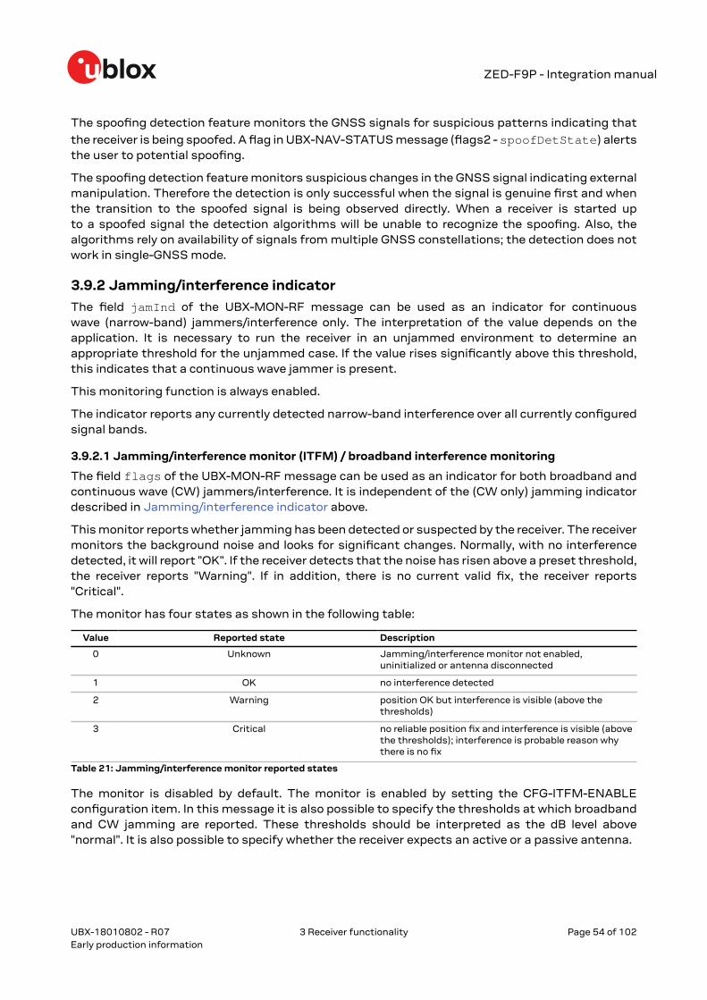
ZED-F9P - Integration manual
The spoofing detection feature monitors the GNSS signals for suspicious patterns indicating that
the receiver is being spoofed. A flag in UBX-NAV-STATUS message (flags2 - spoofDetState) alertsthe user to potential spoofing.
The spoofing detection feature monitors suspicious changes in the GNSS signal indicating externalmanipulation. Therefore the detection is only successful when the signal is genuine first and whenthe transition to the spoofed signal is being observed directly. When a receiver is started upto a spoofed signal the detection algorithms will be unable to recognize the spoofing. Also, thealgorithms rely on availability of signals from multiple GNSS constellations; the detection does notwork in single-GNSS mode.
3.9.2 Jamming/interference indicatorThe field jamInd of the UBX-MON-RF message can be used as an indicator for continuouswave (narrow-band) jammers/interference only. The interpretation of the value depends on theapplication. It is necessary to run the receiver in an unjammed environment to determine anappropriate threshold for the unjammed case. If the value rises significantly above this threshold,this indicates that a continuous wave jammer is present.
This monitoring function is always enabled.
The indicator reports any currently detected narrow-band interference over all currently configuredsignal bands.
3.9.2.1 Jamming/interference monitor (ITFM) / broadband interference monitoring
The field flags of the UBX-MON-RF message can be used as an indicator for both broadband andcontinuous wave (CW) jammers/interference. It is independent of the (CW only) jamming indicatordescribed in Jamming/interference indicator above.
This monitor reports whether jamming has been detected or suspected by the receiver. The receivermonitors the background noise and looks for significant changes. Normally, with no interferencedetected, it will report "OK". If the receiver detects that the noise has risen above a preset threshold,the receiver reports "Warning". If in addition, there is no current valid fix, the receiver reports"Critical".
The monitor has four states as shown in the following table:
Value Reported state Description
0 Unknown Jamming/interference monitor not enabled,uninitialized or antenna disconnected
1 OK no interference detected
2 Warning position OK but interference is visible (above thethresholds)
3 Critical no reliable position fix and interference is visible (abovethe thresholds); interference is probable reason whythere is no fix
Table 21: Jamming/interference monitor reported states
The monitor is disabled by default. The monitor is enabled by setting the CFG-ITFM-ENABLEconfiguration item. In this message it is also possible to specify the thresholds at which broadbandand CW jamming are reported. These thresholds should be interpreted as the dB level above"normal". It is also possible to specify whether the receiver expects an active or a passive antenna.
UBX-18010802 - R07
3 Receiver functionality Page 54 of 102Early production information

ZED-F9P - Integration manual
The monitoring algorithm relies on comparing the currently measured spectrum with areference from when a good fix was obtained. Thus the monitor will only function when thereceiver has had at least one (good) first fix, and will report "Unknown" before this time.
The monitor is reporting any currently detected interference over all currently configured signalbands.
3.9.3 GNSS receiver integrity
3.9.3.1 Secure boot
The ZED-F9P boots only with firmware images that are signed by u-blox. This prevents the executionof non-genuine firmware images run on the receiver.
3.9.3.2 Secure firmware update
The firmware image itself is encrypted and signed by u-blox. The ZED-F9P verify the signature ateach start.
3.10 u-blox protocol feature descriptions
3.10.1 Broadcast navigation dataThis section describes the data reported via UBX-RXM-SFRBX.
The UBX-RXM-SFRBX reports the broadcast navigation data message collected by the receiverfrom each tracked signal. When enabled, a separate message is generated every time the receiverdecodes a complete subframe of data from a tracked signal. The data bits are reported, as received,including preambles and error checking bits as appropriate. However because there is considerablevariation in the data structure of the different GNSS signals, the form of the reported data alsovaries. Indeed, although this document uses the term "subframe" generically, it is not strictly thecorrect term for all GNSS (e.g. GLONASS has "strings" and Galileo has "pages").
3.10.1.1 Parsing navigation data subframes
Each UBX-RXM-SFRBX message contains a subframe of data bits appropriate for the relevantGNSS, delivered in a number of 32-bit words, as indicated by numWords field.
Due to the variation in data structure between different GNSS, the most important step in parsinga UBX-RXMSFRBX message is to identify the form of the data. This should be done by readingthe gnssId field, which indicates which GNSS the data was decoded from. In almost all cases, thisis sufficient to indicate the structure and the following sections are organized by GNSS for thatreason. However, in some cases the identity of the GNSS is not sufficient, and this is described,where appropriate, in the following sections.
In most cases, the data does not map perfectly into a number of 32-bit words and, consequently,some of the words reported in UBX-RXM-SFRBX messages contain fields marked as "Pad". Thesefields should be ignored and no assumption should be made about their contents.
UBX-RXM-SFRBX messages are only generated when complete subframes are detected by thereceiver and all appropriate parity checks have passed.
Where the parity checking algorithm requires data to be inverted before it is decoded (e.g. GPSL1C/A), the receiver carries this out before the message output. Therefore, users can process datadirectly and do not need to worry about repeating any parity processing.
UBX-18010802 - R07
3 Receiver functionality Page 55 of 102Early production information

ZED-F9P - Integration manual
The meaning of the content of each subframe depends on the sending GNSS and is described in therelevant Interface Control Documents (ICD).
3.10.1.2 GPS
The data structure in the GPS L1C/A and L2C signals is dissimilar and thus the UBX-RXM-SFRBXmessage structure differs as well. For the GPS L1C/A and L2C signals it is as follows:
3.10.1.2.1 GPS L1C/AFor GPS L1C/A signals, there is a fairly straightforward mapping between the reported subframeand the structure of subframe and words described in the GPS ICD. Each subframe comprises tendata words, which are reported in the same order they are received.
Each word is arranged as follows:
Figure 24: GPS L1C/A subframe word
3.10.1.2.2 GPS L2CFor GPS L2C signals each reported subframe contains the CNAV message as described in the GPSICD. The ten words are arranged as follows:
Figure 25: GPS L2C subframe words
UBX-18010802 - R07
3 Receiver functionality Page 56 of 102Early production information
ZED-F9P - Integration manual
3.10.1.3 GLONASS
For GLONASS L1OF and L2OF signals, each reported subframe contains a string as described in theGLONASS ICD. This string comprises 85 data bits which are reported over three 32-bit words in theUBX-RXM-SFRBX message. Data bits 1 to 8 are always a hamming code, whilst bits 81 to 84 are astring number and bit 85 is the idle chip, which should always have a value of zero. The meaning ofother bits vary with string and frame number.
The fourth and final 32-bit word in the UBX-RXM-SFRBX message contains frame and superframenumbers (where available). These values are not actually transmitted by the SVs, but are deducedby the receiver and are included to aid decoding of the transmitted data. However, the receiver doesnot always know these values, in which case a value of zero is reported.
The four words are arranged as follows:
Figure 26: GLONASS subframe words
In some circumstances, (especially on startup) the receiver may be able to decode data from aGLONASS SV before it can identify the SV. When this occurs UBX-RXM-SFRBX messages will beissued with an svId of 255 to indicate "unknown".
3.10.1.4 BeiDou
For BeiDou B1I D1, B1I D2, B2I D1, B2I D2 signals, there is a fairly straightforward mapping betweenthe reported subframe and the structure of subframe and words described in the BeiDou ICD. Eachsubframe comprises ten data words, which are reported in the same order they are received.
Each word is arranged as follows:
UBX-18010802 - R07
3 Receiver functionality Page 57 of 102Early production information

ZED-F9P - Integration manual
Figure 27: BeiDou subframe word
Note that as the BeiDou data words only comprise 30 bits, the 2 most significant bits in each wordreported by UBX-RXM-SFRBX are padding and should be ignored.
3.10.1.5 Galileo
The Galileo E1 C/B and E5 bl/bQ signals both transmit the I/NAV message but in differentconfigurations. The UBX-RXM-SFRBX structures for them are as follows.
3.10.1.5.1 Galileo E1 C/BFor Galileo E1 C/B signals, each reported subframe contains a pair of I/NAV pages as described inthe Galileo ICD.
For Galileo "Nominal" pages the eight words are arranged as follows:
UBX-18010802 - R07
3 Receiver functionality Page 58 of 102Early production information

ZED-F9P - Integration manual
Figure 28: Galileo E1 C/B subframe words
3.10.1.5.2 Galileo E5 bI/bQFor Galileo E5 bI/bQ signals, each reported subframe contains a pair of I/NAV pages as described inthe Galileo ICD. Galileo pages can either be "Nominal" or "Alert" pages. For Nominal pages the eightwords are arranged as follows:
UBX-18010802 - R07
3 Receiver functionality Page 59 of 102Early production information

ZED-F9P - Integration manual
Figure 29: Galileo E5 bI/bQ subframe words
Alert pages are reported in very similar manner, but the page type bits will have value 1 and thestructure of the eight words will be slightly different (as indicated by the Galileo ICD).
3.10.1.6 QZSS
The structure of the data delivered by QZSS L1C/A signals is effectively identical to that for GPS(L1C/A).
Similarly the QZSS L2C signal is effectively identical to the GPS (L2C).
3.10.1.7 Summary
The following table gives a summary of the different data message formats reported by the UBX-RXM-SFRBX message:
UBX-18010802 - R07
3 Receiver functionality Page 60 of 102Early production information

ZED-F9P - Integration manual
GNSS Signal gnssId sigId numWords period
GPS L1C/A 0 0 10 6s
SBAS L1C/A 1 0 8 1s
GPS L2CL 0 3 10 12s
GPS L2CM 0 4 10 12s
Galileo E1 C 2 0 8 2s
Galileo E1 B 2 1 8 2s
Galileo E5 bl 2 5 8 2s
Galileo E5 bQ 2 6 8 2s
BeiDou B1I D1 3 0 10 6s
BeiDou B1I D2 3 1 10 0.6s
BeiDou B2I D1 3 2 10 0.6s
BeiDou B2I D2 3 3 10 0.6s
QZSS L1C/A 5 0 10 6s
QZSS L2CM 5 4 10 12s
QZSS L2CL 5 5 10 12s
GLONASS L1OF 6 0 4 2s
GLONASS L2OF 6 2 4 2s
Table 22: Data message formats reported by UBX-RXM-SFRBX
3.11 Forcing a receiver resetTypically, in GNSS receivers, a distinction is made between cold, warm, and hot start, depending onthe type of valid information the receiver has at the time of the restart.
• Cold start: In cold start mode, the receiver has no information from the last position (e.g.time, velocity, frequency etc.) at startup. Therefore, the receiver must search the full time andfrequency space, and all possible satellite numbers. If a satellite signal is found, it is trackedto decode the ephemeris (18-36 seconds under strong signal conditions), whereas the otherchannels continue to search satellites. Once there is a sufficient number of satellites withvalid ephemeris, the receiver can calculate position and velocity data. Other GNSS receivermanufacturers call this startup mode Factory startup.
• Warm start: In warm start mode, the receiver has approximate information for time, position,and coarse satellite position data (Almanac). In this mode, after power-up, the receivernormally needs to download ephemeris before it can calculate position and velocity data.As the ephemeris data usually is outdated after 4 hours, the receiver will typically start witha warm start if it has been powered down for more than 4 hours. In this scenario, severalaugmentations are possible. See Multiple GNSS assistance.
• Hot start: In hot start mode, the receiver was powered down only for a short time (4 hoursor less), so that its ephemeris is still valid. Since the receiver does not need to downloadephemeris again, this is the fastest startup method.
Using the UBX-CFG-RST message, you can force the receiver to reset and clear data, in order to seethe effects of maintaining/losing such data between restarts. For this, the UBX-CFG-RST message
offers the navBbrMask field, where hot, warm and cold starts can be initiated, and also othercombinations thereof.
The reset type can also be specified. This is not related to GNSS, but to the way the software restartsthe system.
• Hardware reset uses the on-chip watchdog, in order to electrically reset the chip. This is animmediate, asynchronous reset. No Stop events are generated.
UBX-18010802 - R07
3 Receiver functionality Page 61 of 102Early production information

ZED-F9P - Integration manual
• Controlled software reset terminates all running processes in an orderly manner and, oncethe system is idle, restarts operation, reloads its configuration and starts to acquire and trackGNSS satellites.
• Controlled software reset (GNSS only) only restarts the GNSS tasks, without reinitializing thefull system or reloading any stored configuration.
• Hardware reset uses the on-chip watchdog. This is a reset after shutdown.• Controlled GNSS stop stops all GNSS tasks. The receiver will not be restarted, but will stop any
GNSS-related processing.• Controlled GNSS start starts all GNSS tasks.
UBX-18010802 - R07
3 Receiver functionality Page 62 of 102Early production information

ZED-F9P - Integration manual
4 DesignThis section provides information to help carry out a successful schematic and PCB designintegrating the ZED-F9P.
Do not load Pin 4 (ANT_DETECT) with a capacitance more than 1 nF.
4.1 Pin assignmentThe pin assignment of the ZED-F9P module is shown in Figure 30. The defined configuration of thePIOs is listed in Table 23.
The ZED-F9P is an LGA package with the I/O on the outside edge and central ground pads.
Figure 30: ZED-F9P pin assignment
Pin No Name I/O Description
1 GND - Ground
2 RF_IN I RF input
3 GND - Ground
4 ANT_DETECT I Active antenna detect - default active high
5 ANT_OFF O External LNA disable - default active high
6 ANT_SHORT_N I Active antenna short detect - default active low
7 VCC_RF O Voltage for external LNA
UBX-18010802 - R07
4 Design Page 63 of 102Early production information

ZED-F9P - Integration manual
Pin No Name I/O Description
8 Reserved - Reserved
9 Reserved - Reserved
10 Reserved - Reserved
11 Reserved - Reserved
12 GND - Ground
13 Reserved - Reserved
14 GND - Ground
15 Reserved - Reserved
16 Reserved - Reserved
17 Reserved - Reserved
18 Reserved - Reserved
19 GEOFENCE_STAT O Geofence status, user defined
20 RTK_STAT O RTK status: 0 (RTK fixed), Blinking (receiving and using RTCM corrections), 1(otherwise)
21 Reserved - Reserved
22 Reserved - Reserved
23 Reserved - Reserved
24 Reserved - Reserved
25 Reserved - Reserved
26 RXD2 I Correction UART input
27 TXD2 O Correction UART output
28 Reserved - Reserved
29 Reserved - Reserved
30 Reserved - Reserved
31 Reserved - Reserved
32 GND - Ground
33 VCC I Voltage supply
34 VCC I Voltage supply
35 Reserved - Reserved
36 V_BCKP I Backup supply voltage
37 GND - Ground
38 V_USB I USB supply
39 USB_DM I/O USB data
40 USB_DP I/O USB data
41 GND - Ground
42 TXD / SPI_MISO O Host UART output if D_SEL = 1(or open). SPI_MISO if D_SEL = 0
43 RXD / SPI_MOSI I Host UART input if D_SEL = 1(or open). SPI_MOSI if D_SEL = 0
44 SDA / SPI_CS_N I/O I2C Data if D_SEL = 1 (or open). SPI Chip Select if D_SEL = 0
45 SCL / SPI_CLK I/O I2C Clock if D_SEL = 1(or open). SPI Clock if D_SEL = 0
46 TX_READY O TX_Buffer full and ready for TX of data
47 D_SEL I Interface select for pins 42-45
48 GND - Ground
49 RESET_N I RESET_N
50 SAFEBOOT_N I SAFEBOOT_N (for future service, updates and reconfiguration, leave OPEN)
UBX-18010802 - R07
4 Design Page 64 of 102Early production information

ZED-F9P - Integration manual
Pin No Name I/O Description
51 EXTINT I External Interrupt Pin
52 Reserved - Reserved
53 TIMEPULSE O Time pulse
54 Reserved - Reserved
Table 23: ZED-F9P pin assignment
4.2 Power supplyThe u-blox ZED-F9P module has three power supply pins: VCC, V_BCKP and V_USB.
4.2.1 VCC: Main supply voltageThe VCC pin is connected to the main supply voltage. During operation, the current drawn by themodule can vary by some orders of magnitude. For this reason, it is important that the supplycircuitry be able to support the peak power for a short time (see the ZED-F9P Data sheet [1] forspecification).
The module integrates a DC/DC converter, which allows reduced power consumption.
When switching from backup mode to normal operation or at start-up, u-blox ZED-F9Pmodules must charge the internal capacitors in the core domain. In certain situations, thiscan result in a significant current draw. For low-power applications using backup mode, it isimportant that the power supply or low ESR capacitors at the module input can deliver thiscurrent/charge.
To reduce peak current during power on, users can employ an LDO that has an in-builtcurrent limiter
Do not add any series resistance greater than 0.2 Ω to the VCC supply as it will generateinput voltage noise due to dynamic current conditions.
For the ZED-F9P module the equipment must be supplied by an external limited powersource in compliance with the clause 2.5 of the standard IEC 60950-1.
4.2.2 V_BCKP: Backup supply voltageIf the module supply has a power failure, the V_BCKP pin supplies the real-time clock (RTC) andbattery backed RAM (BBR). Use of valid time and the GNSS orbit data at start up will improve theGNSS performance, as with hot starts and warm starts.
If V_BCKP is not provided, the module performs a cold start at power up.
If a host is connected to ZED-F9P, V_BCKP can be partially emulated by using UBX-UPD-SOSfunctionality. BBR data can saved to the host and restored at startup. See Interface description formore information.
Avoid high resistance on the V_BCKP line: During the switch from main supply to backupsupply, a short current adjustment peak can cause a high voltage drop on the pin withpossible malfunctions.
Add a 2 uF capacitor on the V_BCKP pin to absorb the current adjustment peak whenswitching from VCC to V_BCKP supply.
If no backup supply voltage is available, connect the V_BCKP pin to VCC.
Allow all I/O including UART and other interfaces to float or connect to a high impedance inHW backup mode (V_BCKP supplied when VCC is removed). See the Interfaces section.
UBX-18010802 - R07
4 Design Page 65 of 102Early production information

ZED-F9P - Integration manual
Real time clock (RTC)
The real-time clock (RTC) is driven by a 32-kHz oscillator using an RTC crystal. If VCC is removedwhilst a battery is connected to V_BCKP, most of the receiver is switched off leaving the RTC andBBR powered. This operating mode is called Hardware Backup Mode which enables time keeping andall relevant data to be saved to allow a hot or warm start.
4.2.3 ZED-F9P power supplyThe ZED-F9P high precision receiver requires a low-noise, low-dropout voltage, very low sourceimpedance power supply of 3.3 V typically. No inductors or ferrite beads should be used from LDOto the module VCC pin. The peak currents need to be taken into account for the source supplyingthe LDO for the module.
A power supply fed by 5 V is shown in the figure below. This example circuit is intended only for themodule supply.
Figure 31: ZED-F9P power supply
4.3 ZED-F9P minimal designThe minimal electrical circuit for ZED-F9P operation using the UART1 interface is shown in Figure32 below.
UBX-18010802 - R07
4 Design Page 66 of 102Early production information

ZED-F9P - Integration manual
Figure 32: Minimal ZED-F9P design
For a minimal design with the ZED-F9P GNSS modules, the following functions and pins should beconsidered:
• Connect the power supply to VCC and V_BCKP.• If hot or warm start operations are needed, connect a backup battery to V_BCKP.• If USB is not used connect V_USB to ground.• Ensure an optimal ground connection to all ground pins of the ZED-F9P GNSS module.• If antenna bias is required, see ZED-F9P antenna bias section.
The host interface typically supplies the RTCM messages required for RTK operation.
4.4 Antennau-blox recommends using an active antenna with ZED-F9P.
If an active antenna needs to be implemented in an application case, it is recommended that anOEM active antenna module be used that meets our specification. To implement the required RFcircuitry and source the required components to meet group delay specification is not a simpleprocess compared to previous L1-only implementation.
UBX-18010802 - R07
4 Design Page 67 of 102Early production information
ZED-F9P - Integration manual
Figure 33: u-blox low cost dual-band antenna internal structure
A suitable ground plane is required for the antenna to achieve good performance.
Location of the antenna is critical to reach the stated performance. Unsuitable locationscould include, under vehicle dash, rear-view mirror location, etc.
L1 + L2/E5b active antenna required specifications
Parameter Specification
Antenna type Active antenna
Minimum active antenna gain3 17 dB
Maximum active antenna gain3 50 dBActive antenna recommendations
Noise figure <4 dB
L1 band antenna gain4 1559 - 1606 MHz: 3 dBic typ.
L2/E5b band antenna gain5 1197 - 1249 MHz: 2 dBic typ.
Polarization RHCP
Axial ratio 2 dB max at Zenith
Phase center variation <10 mm over elevation/azimuth
Group delay variation in-band6 10 ns max at each GNSS system bandwidth. Note:Inter-signal requirement 50 ns max.
EMI immunity out-of-band7 30 V/m
Out-of-band 8 rejection 40 dB typ
ESD circuit protection 15 kV human body model air discharge
Table 24: Antenna specifications for ZED-F9P modules
3 Including passive losses (filters, cables, connectors etc.)4 Measured with a ground plane d=150 mm5 Measured with a ground plane d=150 mm6 GNSS system bandwidths: 1559… 1563 MHz; 1573… 1578 MHz; 1598… 1606 MHz; 1192… 1212 MHz; 1197… 1217
MHz; 1223… 1231 MHz; 1242… 1249 MHz7 Exception L1 and L2 bands +/- 200 MHz, emphasis on cellular bands8 GNSS system bandwidths: 1559… 1563 MHz; 1573… 1578 MHz; 1598… 1606 MHz; 1192… 1212 MHz; 1197… 1217
MHz; 1223… 1231 MHz; 1242… 1249 MHz
UBX-18010802 - R07
4 Design Page 68 of 102Early production information

ZED-F9P - Integration manual
The antenna system should include filtering to ensure adequate protection from nearbytransmitters. Take care in the selection of antennas placed close to cellular or Wi-Fi transmittingantennas.
4.4.1 Antenna biasActive antennas have an integrated low-noise amplifier that contributes an additional current oftypically 5 to 20 mA to the system's power consumption budget. If customers do not want to makeuse of the antenna supervisor function the filtered VCC_RF supply voltage output can supply theantenna if the supply voltage of the ZED-F9P module matches the antenna working voltage (e.g.3.0 V).
A series current limiting resistor is required to prevent short circuits destroying the bias-tinductor.
The bias-t inductor must be chosen for multi-band operation, a value of 120 nH 5% isrecommended for the recommended Murata L part. It has a self-resonance frequency of 1GHz and a high impedance (> 500 Ω) at L-band frequencies.
The recommended bias-t inductor (Murata LQW15ANR12J00) has a maximum current capacity of110 mA. Hence the current is limited to 70 mA at 3.3V using an active limiter in the recommendedcircuit shown in Figure 35 below. A 10 Ω resistor (R2) is provided to measure the current. This resistorpower rating must be chosen to ensure reliability in the chosen circuit design.
Figure 34: ZED-F9P antenna bias inductor impedance
A recommended circuit design for an active antenna bias is shown below. This example shows anexternal voltage of 3.3V with current limiting as described above. An ESD protection diode shouldalso be connected to the input as shown.
UBX-18010802 - R07
4 Design Page 69 of 102Early production information

ZED-F9P - Integration manual
Figure 35: ZED-F9P reference design for antenna bias
L1: MURATA LQW15A LQW15ANR12J00 0402 120N 5% 0.11A -55/+125C
D1: TYCO, 0.25PF, PESD0402-140 -55/+125C
C3: MURATA GRM033R61E104KE14 CER X5R 0201 100N 10% 25V
R2: RES THICK FILM CHIP 1206 10R 5% 0.25W
It is recommended to use active current limiting. If active current limiting is not used, the followingimportant points covered below need to be taken into account:
Figure 36: ZED-F9P VCC_RF antenna bias
The bias-t inductor and current limiting resistor must be selected to be reliable with a short-cirquit on the antenna feed if no active current limiter is used. Our recommended part hasa limit of 110 mA. A part with a higher current capability will be needed if the short circuitcurrent is as described here. This will also be affected by the voltage level of the antenna
UBX-18010802 - R07
4 Design Page 70 of 102Early production information
ZED-F9P - Integration manual
bias supply due to power dissipation. Take the current limit capability of the antenna biassupply into consideration. In the case where the module supplies the voltage via VCC_RF, ahigher value resistor will be needed to ensure the module supply inductor is protected. Thecurrent should be limited to below 150 mA at the module supply voltage under short-cirquitconditions. In this case a value of 17 Ω or more is required at a module supply of 3 V to limitshort circuit current to 150 mA. The DC resistance of the bias-t inductor is assumed to be1-2 Ω and the module internal feed inductor is assumed to be 1.2 Ω.
If the VCC_RF voltage does not match with the supply voltage of the active antenna, use a filteredexternal supply.
The power dissipation in the resistor and inductor needs to be taken into account based onthe supply voltage and short circuit current. The bias-t inductor current capability and thebias resistor value need to be calculated as shown above. The supply voltage for the bias-tand its current capability is part of the calculation.
Figure 37: ZED-F9P external voltage antenna bias
4.5 EOS/ESD precautionsWhen integrating GNSS receivers into wireless systems, careful consideration must be given toelectromagnetic and voltage susceptibility issues. Wireless systems include components whichcan produce Electrostatic Discharge (ESD), Electrical Overstress (EOS) and Electro-MagneticInterference (EMI). CMOS devices are more sensitive to such influences because their failuremechanism is defined by the applied voltage, whereas bipolar semiconductors are more susceptibleto thermal overstress. The following design guidelines are provided to help in designing robust yetcost-effective solutions.
To avoid overstress damage during production or in the field it is essential to observe strictEOS/ESD/EMI handling and protection measures.
To prevent overstress damage at the RF_IN of your receiver, never exceed the maximuminput power as specified in the u-blox ZED-F9P Data sheet [1].
4.5.1 ESD protection measuresGNSS receivers are sensitive to Electrostatic Discharge (ESD). Special precautions arerequired when handling. Most defects caused by ESD can be prevented by following strictESD protection rules for production and handling. When implementing passive antennapatches or external antenna connection points, then additional ESD measures as shown inthe figure below can also avoid failures in the field.
UBX-18010802 - R07
4 Design Page 71 of 102Early production information

ZED-F9P - Integration manual
Figure 38: RF ESD precautions
4.5.2 EOS precautionsElectrical overstress (EOS) usually describes situations when the maximum input power exceedsthe maximum specified ratings. EOS failure can happen if RF emitters are close to a GNSS receiveror its antenna. EOS causes damage to the chip structures. If the RF_IN is damaged by EOS, it is hardto determine whether the chip structures have been damaged by ESD or EOS.
EOS protection measures as shown in the figure below are recommended for any designs combiningwireless communication transceivers (e.g. GSM, GPRS) and GNSS in the same design or in closeproximity.
Figure 39: Active antenna EOS protection
4.5.3 Safety precautionsThe ZED-F9P must be supplied by an external limited power source in compliance with the clause2.5 of the standard IEC 60950-1. In addition to external limited power source, only Separated orSafety Extra-Low Voltage (SELV) circuits are to be connected to the module including interfaces andantennas.
For more information about SELV circuits see section 2.2 in Safety standard IEC 60950-1.
4.6 Electromagnetic interference on I/O linesAny I/O signal line with a length greater than approximately 3 mm can act as an antenna and maypick up arbitrary RF signals transferring them as noise into the GNSS receiver. This specificallyapplies to unshielded lines, in which the corresponding GND layer is remote or missing entirely, andlines close to the edges of the printed circuit board.
If, for example, a cellular signal radiates into an unshielded high-impedance line, it is possible togenerate noise in the order of volts and not only distort receiver operation but also damage itpermanently. Another type of interference can be caused by noise generated at the PIO pins that
UBX-18010802 - R07
4 Design Page 72 of 102Early production information
ZED-F9P - Integration manual
emits from unshielded I/O lines. Receiver performance may be degraded when this noise is coupledinto the GNSS antenna.
EMI protection measures are particularly useful when RF emitting devices are placed next to theGNSS receiver and/or to minimize the risk of EMI degradation due to self-jamming. An adequatelayout with a robust grounding concept is essential in order to protect against EMI.
Intended Use: In order to mitigate any performance degradation of a radio equipment underEMC disturbance, system integration shall adopt appropriate EMC design practice and notcontain cables over three meters on signal and supply ports.
4.6.1 General notes on interference issuesReceived GNSS signal power at the antenna is very low. At the nominal received signal strength (-128dBm) it is below the thermal noise floor of -111 dBm. Due to this fact, a GNSS receiver is susceptibleto interference from nearby RF sources of any kind. Two cases can be distinguished:
• Out-of-band interference: Typically any kind of wireless communications system (e.g. LTE,GSM, CDMA, 3G, WLAN, Bluetooth, etc.) may emit its specified maximum transmit power inclose proximity to the GNSS receiving antenna, especially if such a system is integrated withthe GNSS receiver. Even at reasonable antenna selectivity, destructive power levels may reachthe RF input of the GNSS receiver. Also, larger signal interferers may generate intermodulationproducts inside the GNSS receiver front-end that fall into the GNSS band and contribute to in-band interference
• In-band interference: Although the GNSS band is kept free from intentional RF signal sourcesby radio-communications standards, many devices emit RF power into the GNSS band at levelsmuch higher than the GNSS signal itself. One reason is that the frequency band above 1 GHzis not well regulated with regards to EMI, and even if permitted, signal levels are much higherthan GNSS signal power. Notably, all types of digital equipment, such as PCs, digital cameras,LCD screens, etc. tend to emit a broad frequency spectrum up to several GHz of frequency. Alsowireless transmitters may generate spurious emissions that fall into GNSS band
As an example, GSM uses power levels of up to 2 W (+33 dBm). The absolute maximum powerinput at the RF input of the GNSS receiver can be +15 dBm. The GSM specification allows spuriousemissions for GSM transmitters of up to +36 dBm, while the GNSS signal is less than -128dBm. By simply comparing these numbers it is obvious that interference issues must be seriouslyconsidered in any design of a GNSS receiver. Different design goals may be achieved throughdifferent implementations:
• The primary focus is preventing the destruction of the receiver from large input signals. Herethe GNSS performance under interference conditions is not important and suppression of theGNSS signal is permitted. It is sufficient to just observe the maximum RF power ratings of allthe components in the RF input path.
• GNSS performance must be guaranteed even under interference conditions. In that case, notonly the maximum power ratings of the components in the receive patch must be observed.Further, non-linear effects like gain compression, NF degradation (desensitization) andintermodulation must be analyzed.
Pulsed interference with a low duty cycle such as GSM may be destructive due to the highpeak power levels.
4.6.2 In-band interference mitigationWith in-band interference, the signal frequency is very close to the GNSS frequency. Suchinterference signals are typically caused by harmonics from displays, micro-controller operation, bussystems, etc. Measures against in-band interference include:
UBX-18010802 - R07
4 Design Page 73 of 102Early production information

ZED-F9P - Integration manual
• Maintaining a good grounding concept in the design• Shielding• Layout optimization• Low-pass filtering of noise sources, e.g. digital signal lines• Remote placement of the GNSS antenna, far away from noise sources• Adding an LTE, CDMA, GSM, WCDMA, BT band-pass filter before antenna
4.6.3 Out-of-band interferenceOut-of-band interference is caused by signal frequencies that are different from the GNSS carrierfrequency. The main sources are wireless communication systems such as LTE, GSM, CDMA,WCDMA, Wi-Fi, BT, etc.
Measures against out-of-band interference include maintaining a good grounding concept in thedesign and adding a GNSS band-pass filter into the antenna input line to the receiver.
For GSM applications, such as typical handset design, an isolation of approximately 20 dB can bereached with careful placement of the antennas. If this is insufficient, an additional SAW filter isrequired on the GNSS receiver input to block the remaining GSM transmitter energy.
4.7 LayoutThis section details layout and placement requirements of the ZED-F9P high precision receiver.
4.7.1 PlacementGNSS signals at the surface of the Earth are below the thermal noise floor. A very important factor inachieving maximum GNSS performance is the placement of the receiver on the PCB. The placementused may affect RF signal loss from antenna to receiver input and enable interference into thesensitive parts of the receiver chain, including the antenna itself. When defining a GNSS receiverlayout, the placement of the antenna with respect to the receiver, as well as grounding, shielding andinterference from other digital devices are crucial issues and need to be considered very carefully.
Signal loss on the RF connection from antenna to receiver input must be minimized as much aspossible. Hence, the connection to the antenna must be kept as short as possible.
Ensure that RF critical circuits are clearly separated from any other digital circuits on the systemboard. To achieve this, position the receiver digital part closer to the digital section of the systemPCB and have the RF section and antenna placed as far as possible away from the other digitalcircuits on the board.
A proper GND concept shall be followed: The RF section shall not be subject to noisy digital supplycurrents running through its GND plane.
Care must also be exercised with placing the receiver in proximity to circuitry that can emit heat. TheRF part of the receiver is very sensitive to temperature and sudden changes can have an adverseimpact on performance.
The TCXO of a GNSS receiver is a temperature-sensitive device. Avoid high temperaturedrift and air convection.
4.7.2 Package footprint, copper and paste maskCopper and solder mask dimensioning recommendations for the ZED-F9P module packages areprovided in this section.
UBX-18010802 - R07
4 Design Page 74 of 102Early production information

ZED-F9P - Integration manual
These are recommendations only and not specifications. The exact copper, solder and pastemask geometries, distances, stencil thicknesses and solder paste volumes must be adaptedto the specific production processes (e.g. soldering etc.) of the customer.
Refer to the ZED-F9P Data sheet [1] for the mechanical dimensions.
4.7.2.1 Footprint
Figure 40: ZED-F9P suggested footprint (i.e. copper mask)
UBX-18010802 - R07
4 Design Page 75 of 102Early production information

ZED-F9P - Integration manual
4.7.2.2 Paste mask
Figure 41: ZED-F9P suggested paste mask
4.7.3 Layout guidanceThe presented layout guidance reduces the risk of performance issues at design level.
4.7.3.1 RF In trace
The RF in trace has to work in the combined GNSS L1 + L2 signal band.
A grounded co-planar RF trace is recommended as it provides the maximum shielding from noisewith adequate vias to the ground layer.
The RF trace must be shielded by vias to ground along the entire length of the trace and the ZED-F9P RF_IN pad should be surrounded by vias as shown in the figure below.
UBX-18010802 - R07
4 Design Page 76 of 102Early production information

ZED-F9P - Integration manual
Figure 42: RF input trace
The RF_IN trace on the top layer should be referenced to a suitable ground layer.
4.7.3.2 Vias for the ground pads
The ground pads under the ZED-F9P high precision receiver need to be grounded with vias to thelower ground layer of the PCB. A solid ground layer fill on the top layer of the PCB is recommended.This is shown in the figure below.
Figure 43: Top layer fill and vias
4.7.3.3 VCC pads
The VCC pads for the ZED-F9P high precision receiver must have as low impedance as possible withlarge vias to the lower power layer of the PCB. The VCC pads need a large combined pad and the de-coupling capacitors must be placed as close as possible. This is shown in the figure below.
UBX-18010802 - R07
4 Design Page 77 of 102Early production information

ZED-F9P - Integration manual
Figure 44: VCC pads
4.8 Design guidance
4.8.1 General considerationsDo not load Pin 4 (ANT_DETECT) with a capacitance more than 1 nF.
Check power supply requirements and schematic:
• Is the power supply voltage within the specified range and noise-free?• If USB is not used, connect the V_USB pin to ground.• For USB devices: Is the V_USB voltage within the specified range?• It is recommended to have a separate LDO for V_USB that is enabled by the module VCC. This is
to comply with the USB self-powered specification.• If USB is used, is there a 1 uF capacitor right near the V_USB pin? This is just for the V_USB pin.• Is there a 1 uF cap right next to the module VCC pin?• Compare the peak current consumption of the ZED-F9P GNSS module with the specification of
your power supply.• GNSS receivers require a stable power supply. Avoid series resistance (less than 0.2 Ω) in
your power supply line (the line to VCC) to minimize the voltage ripple on VCC. See the ZED-F9P Power supply section in the Design chapter for more information on the power supplyrequirements.
• Allow all I/O to Float/High impedance (High-Z) when VCC is not applied.
4.8.2 Backup batteryCheck backup supply requirements and schematic:
• For achieving a minimal Time To First Fix (TTFF) after a power down (warm starts, hot starts),make sure to connect a backup battery to V_BCKP.
• Verify your battery backup supply can provide the battery backup current specified in the ZED-F9P datasheet.
• Allow all I/O including UART and other interfaces to Float/High impedance in HW backup mode(battery back-up connected with VCC removed).
4.8.3 RF front-end circuit optionsIt is important that the RF input is fed by an active antenna meeting the requirements forthe ZED-F9P.
The first stages of the signal processing chain are crucial to the overall receiver performance.
UBX-18010802 - R07
4 Design Page 78 of 102Early production information
ZED-F9P - Integration manual
When an RF input connector is employed this can provide a conduction path for harmful ordestructive electrical signals. If this is a likely factor the RF input should be protected accordingly.
Additional points on the RF input
• What is the expected quality of the signal source (antenna)?• What is the external active antenna signal power?• What is the bandwidth and filtering of the external active antenna?• Does the external antenna and filtering components meet the group delay variation
requirements? This is critical for RTK.
Are destructive RF power levels expected to reach the RF input? Is interference from wirelesstransmitters expected?
• What are the characteristics of these signals (duty cycle, frequency range, power range,spectral purity)?
• What is the expected GNSS performance under interference conditions?
Is there a risk of RF input exposure to excessive ESD stress?
• In the field: Can the user access the connector?• PCB / system assembly: Is there risk that statically charged parts (e.g. patch antennas) may be
discharged through the RF input?
The following subsections provide several options addressing the various questions above:
In some applications, such as cellular transceivers, interference signals may exceed themaximum power rating of the RF_IN input. To avoid device destruction use of external inputprotection is mandatory.
During assembly of end-user devices which contain passive patch antennas, an ESDdischarge may occur during production when pre-charged antennas are soldered to theGNSS receiver board. In such cases, use of external protection in front of RF_IN is mandatoryto avoid device destruction.
ESD discharge cannot be avoided during assembly and / or field use. Note that SAW filters aresusceptible to ESD damage. To provide additional robustness an ESD protection diode may beplaced at the antenna RF connector to GND.
4.8.4 Antenna/RF inputCheck RF input requirements and schematic:
• An OEM active antenna module that meets our requirements should be used if there is a needto integrate the antenna.
• The total maximum noise figure including external LNA (or the LNA in the active antenna)should be around 3 dB.
• Ensure active antenna gain is ideally between 30 - 40 dB gain.• Make sure the antenna is not placed close to noisy parts of the circuitry and does not face any
other noisy elements (for example micro-controller, display).• Signal levels above 40 C/N0 average are required for optimal RTK performance.• Ensure antenna supports both L1 and L2 bands.• Ensure antenna element gain is between 2 and 3 dBic typical for L1 and L2 bands.• Ensure the group delay variation including active antenna is 10 ns max at each GNSS system
bandwidth. Note: Inter-signal requirement 50 ns max.• ESD protection on the RF input is mandatory.• Bias-t inductor must be L1 and L2 band frequency selected with high impedance in the GNSS
band.
UBX-18010802 - R07
4 Design Page 79 of 102Early production information

ZED-F9P - Integration manual
• Ensure RF trace is tuned for 50 Ω to ensure L1 and L2 bandwidth.
4.8.5 Ground padsEnsure the ground pads of the module are connected to ground.
If a patch type antenna is used, a an antenna ground plane with minimum 100 - 150 mm diameteris required.
4.8.6 Schematic designFor a minimal design with the ZED-F9P GNSS modules, consider the following functions and pins:
• Connect the power supply to VCC and V_BCKP.• V_USB: If USB is used it is recommended V_USB is to be powered as per USB self-powered mode
specification.• If USB is not used connect V_USB to ground.• Ensure an optimal ground connection to all ground pins of the ZED-F9P GNSS module.• Choose the required serial communication interfaces (UART, USB, SPI or I2C) and connect the
appropriate pins to your application.• If you need hot or warm start in your application, connect a back-up battery to V_BCKP.• Antenna bias is required, see ZED-F9P antenna bias section.
4.8.7 Layout design-in guideline• Is the receiver placed away from heat sources?• Is the receiver placed away from air-cooling sources?• Is the receiver shielded by a cover/case to prevent the effects of air currents and rapid
environmental temperature changes?• Is the receiver placed as recommended in the Layout and Layout guidance?• Assure a low serial resistance on the VCC power supply line (choose a line width > 400 um).• Keep the power supply line as short as possible.• Add a ground plane underneath the module to reduce interference. This is especially important
for the RF input line.• For improved shielding, add as many vias as possible around the micro strip/co-planar
waveguide, around the serial communication lines, underneath the module, etc.
UBX-18010802 - R07
4 Design Page 80 of 102Early production information
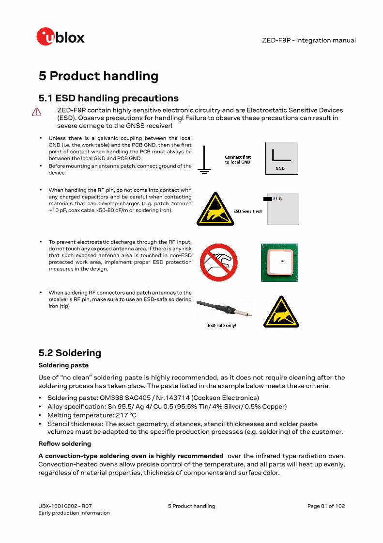
ZED-F9P - Integration manual
5 Product handling
5.1 ESD handling precautionsZED-F9P contain highly sensitive electronic circuitry and are Electrostatic Sensitive Devices(ESD). Observe precautions for handling! Failure to observe these precautions can result insevere damage to the GNSS receiver!
• Unless there is a galvanic coupling between the localGND (i.e. the work table) and the PCB GND, then the firstpoint of contact when handling the PCB must always bebetween the local GND and PCB GND.
• Before mounting an antenna patch, connect ground of thedevice.
• When handling the RF pin, do not come into contact withany charged capacitors and be careful when contactingmaterials that can develop charges (e.g. patch antenna~10 pF, coax cable ~50-80 pF/m or soldering iron).
• To prevent electrostatic discharge through the RF input,do not touch any exposed antenna area. If there is any riskthat such exposed antenna area is touched in non-ESDprotected work area, implement proper ESD protectionmeasures in the design.
• When soldering RF connectors and patch antennas to thereceiver’s RF pin, make sure to use an ESD-safe solderingiron (tip)
5.2 SolderingSoldering paste
Use of “no clean” soldering paste is highly recommended, as it does not require cleaning after thesoldering process has taken place. The paste listed in the example below meets these criteria.
• Soldering paste: OM338 SAC405 / Nr.143714 (Cookson Electronics)• Alloy specification: Sn 95.5/ Ag 4/ Cu 0.5 (95.5% Tin/ 4% Silver/ 0.5% Copper)• Melting temperature: 217 °C• Stencil thickness: The exact geometry, distances, stencil thicknesses and solder paste
volumes must be adapted to the specific production processes (e.g. soldering) of the customer.
Reflow soldering
A convection-type soldering oven is highly recommended over the infrared type radiation oven.Convection-heated ovens allow precise control of the temperature, and all parts will heat up evenly,regardless of material properties, thickness of components and surface color.
UBX-18010802 - R07
5 Product handling Page 81 of 102Early production information
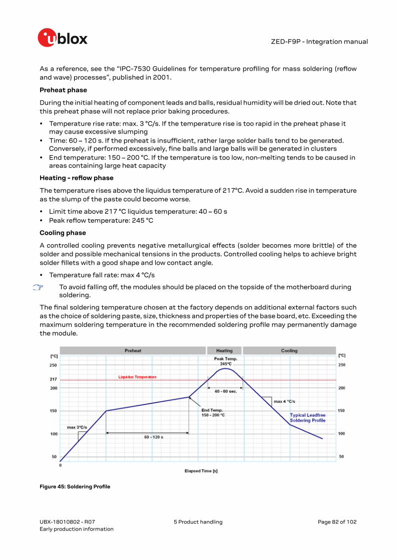
ZED-F9P - Integration manual
As a reference, see the “IPC-7530 Guidelines for temperature profiling for mass soldering (reflowand wave) processes”, published in 2001.
Preheat phase
During the initial heating of component leads and balls, residual humidity will be dried out. Note thatthis preheat phase will not replace prior baking procedures.
• Temperature rise rate: max. 3 °C/s. If the temperature rise is too rapid in the preheat phase itmay cause excessive slumping
• Time: 60 – 120 s. If the preheat is insufficient, rather large solder balls tend to be generated.Conversely, if performed excessively, fine balls and large balls will be generated in clusters
• End temperature: 150 – 200 °C. If the temperature is too low, non-melting tends to be caused inareas containing large heat capacity
Heating - reflow phase
The temperature rises above the liquidus temperature of 217°C. Avoid a sudden rise in temperatureas the slump of the paste could become worse.
• Limit time above 217 °C liquidus temperature: 40 – 60 s• Peak reflow temperature: 245 °C
Cooling phase
A controlled cooling prevents negative metallurgical effects (solder becomes more brittle) of thesolder and possible mechanical tensions in the products. Controlled cooling helps to achieve brightsolder fillets with a good shape and low contact angle.
• Temperature fall rate: max 4 °C/s
To avoid falling off, the modules should be placed on the topside of the motherboard duringsoldering.
The final soldering temperature chosen at the factory depends on additional external factors suchas the choice of soldering paste, size, thickness and properties of the base board, etc. Exceeding themaximum soldering temperature in the recommended soldering profile may permanently damagethe module.
Figure 45: Soldering Profile
UBX-18010802 - R07
5 Product handling Page 82 of 102Early production information

ZED-F9P - Integration manual
Modules must not be soldered with a damp heat process.
Optical inspection
After soldering the module, consider an optical inspection step.
Cleaning
No cleaning with water, solvent, ultrasonic cleaner should be carried out:
• Cleaning with water will lead to capillary effects where water is absorbed in the gap betweenthe baseboard and the module. The combination of residues of soldering flux and encapsulatedwater leads to short circuits or resistor-like interconnections between neighboring pads.
• Cleaning with alcohol or other organic solvents can result in soldering flux residues flooding intothe two housings, areas that are not accessible for post-wash inspections. The solvent will alsodamage the sticker and the ink-jet printed text.
• Ultrasonic cleaning will permanently damage the module, in particular the quartz oscillators.
The best approach is to use a "no clean" soldering paste and eliminate the cleaning step after thesoldering.
Repeated reflow soldering
Only single reflow soldering processes are recommended for boards populated with modules.Modules should not be submitted to two reflow cycles on a board populated with components onboth sides in order to avoid upside down orientation during the second reflow cycle. In this case, themodule should always be placed on that side of the board, which is submitted into the last reflowcycle. The reason for this (besides others) is the risk of the module falling off due to the significantlyhigher weight in relation to other components.
Two reflow cycles can be considered by excluding the above described upside down scenario andtaking into account the rework conditions described in this section.
Repeated reflow soldering processes and soldering the module upside down are notrecommended.
Wave soldering
Base boards with combined through-hole technology (THT) components and surface-mounttechnology (SMT) devices require wave soldering to solder the THT components. Only a single wavesoldering process is encouraged for boards populated with modules.
Rework
We do not recommend using a hot air gun because this is an uncontrolled process and might damagethe module.
Use of a hot air gun can lead to overheating and severely damage the module. Always avoidoverheating the module.
After the module is removed, clean the pads before re-applying solder paste, placing and reflowsoldering a new module.
Never attempt a rework on the module itself, e.g. replacing individual components. Suchactions immediately terminate the warranty.
Conformal coating
Certain applications employ a conformal coating of the PCB using HumiSeal® or other relatedcoating products. These materials affect the RF properties of the GNSS module and it is important
UBX-18010802 - R07
5 Product handling Page 83 of 102Early production information
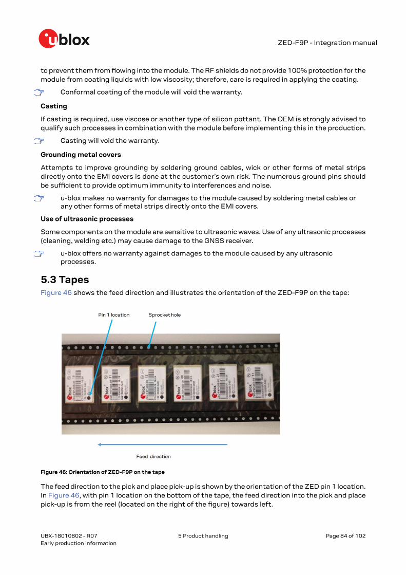
ZED-F9P - Integration manual
to prevent them from flowing into the module. The RF shields do not provide 100% protection for themodule from coating liquids with low viscosity; therefore, care is required in applying the coating.
Conformal coating of the module will void the warranty.
Casting
If casting is required, use viscose or another type of silicon pottant. The OEM is strongly advised toqualify such processes in combination with the module before implementing this in the production.
Casting will void the warranty.
Grounding metal covers
Attempts to improve grounding by soldering ground cables, wick or other forms of metal stripsdirectly onto the EMI covers is done at the customer’s own risk. The numerous ground pins shouldbe sufficient to provide optimum immunity to interferences and noise.
u-blox makes no warranty for damages to the module caused by soldering metal cables orany other forms of metal strips directly onto the EMI covers.
Use of ultrasonic processes
Some components on the module are sensitive to ultrasonic waves. Use of any ultrasonic processes(cleaning, welding etc.) may cause damage to the GNSS receiver.
u-blox offers no warranty against damages to the module caused by any ultrasonicprocesses.
5.3 TapesFigure 46 shows the feed direction and illustrates the orientation of the ZED-F9P on the tape:
Figure 46: Orientation of ZED-F9P on the tape
The feed direction to the pick and place pick-up is shown by the orientation of the ZED pin 1 location.In Figure 46, with pin 1 location on the bottom of the tape, the feed direction into the pick and placepick-up is from the reel (located on the right of the figure) towards left.
UBX-18010802 - R07
5 Product handling Page 84 of 102Early production information

ZED-F9P - Integration manual
The dimensions of the tapes for ZED-F9P are specified in Figure 47 (measurements in mm).
Figure 47: ZED-F9P tape dimensions (mm)
5.4 ReelsThe ZED-F9P high precision receiver GNSS modules are deliverable in quantities of 250 pieces on areel. The ZED-F9P high precision receiver receivers are shipped on Reel Type B, as specified in theu-blox Package Information Guide. See the u-blox Package Information Guide [3].
5.5 Moisture sensitivity levelsThe moisture sensitivity level (MSL) for ZED-F9P is specified in the table below.
Package MSL level
LGA 4
Table 25: MSL level
For MSL standard see IPC/JEDEC J-STD-020, which can be downloaded fromwww.jedec.org.
For more information regarding moisture sensitivity levels, labeling, storage and drying, seethe u-blox Package Information Guide [3].
UBX-18010802 - R07
5 Product handling Page 85 of 102Early production information

ZED-F9P - Integration manual
Appendix
A GlossaryAbbreviation Definition
ANSI American National Standards Institute
ARP Antenna Reference Point
BeiDou Chinese navigation satellite system
BBR Battery-backed RAM
CDMA Code Division Multiple Access
EMC Electromagnetic Compatibility
EMI Electromagnetic Interference
EOS Electrical Overstress
EPA Electrostatic Protective Area
ESD Electrostatic Discharge
Galileo European navigation satellite system
GLONASS Russian navigation satellite system
GND Ground
GNSS Global navigation satellite system
GPS Global Positioning System
GSM Global system for mobile communications
I2C Inter-integrated circuit bus
IEC International Electrotechnical Commission
ITRF International Terrestrial Reference Frame
MB Moving base
MSM Multiple Signal Messages
NTRIP Networked transport of RTCM via internet protocol
PCB Printed Circuit Board
QZSS Quasi-Zenith Satellite System
RF Radio frequency
RTCM Radio Technical Commission for Maritime
RTK Real Time Kinematic
SV Space Vehicle, a satellite
TDOP Time Dilution Of Precision
UBX u-blox
QZSS Quasi-Zenith Satellite System
B RTCM ITRF geodetic modelsReal time kinematic (RTK) is a differential system where the rover uses the reference datum ofthe reference station. The International Terrestrial Reference Frame (ITRF) must be obtained fromthe reference network and then used to transform the rover position output to match the requiredreference frame. The rover does not output the position in the local receiver WGS84 (based onITRF2008) datum, it matches the reference receiver (or base) reference frame. The user application
UBX-18010802 - R07
Appendix Page 86 of 102Early production information

ZED-F9P - Integration manual
needs to do the transformation for use in a mapping application if it does not use the same referenceframe. An offset can occur if this is not done.
The ITRF reference frame years are listed below:
• ITRF94• ITRF96• ITRF97• ITRF2000• ITRF2005• ITRF2008• ITRF2014
There are other similar reference systems used by GNSS correction services, such as the ETRS89.
For example, the EUREF network uses the ETRS89 reference frame. For information, see theirhomepage: EUREF.
See the ITRF website for more information and an online transform calculator: ITRF.
Another online tool is available on the EUREF network page: Transformation.
Figure 48: Transforming between two datums
The user needs to transform the frame of the reference receiver (or base) into the required systembeing used by their application and mapping system. If comparing the rover position with a referencesystem, the same RTCM stream should be used to ensure that the reference and the rover outputthe same position. If the reference system is post-processed, its output must be transformed to thesame ITRF and datum being used by the rover.
For example, when viewing RTK-accurate positions that could be in any ITRF transform referenceframe (based on reference receiver (or base) reference frame) on Google Earth: The heights onGoogle Earth refer to EGM96 and are, therefore, Geoidal heights.
The lat/long are referred to the WGS 84 (ITRF2008) ellipsoid. The result is a visible inaccuracy, andthe RTK receivers' position output must be transformed to the Google Earth transform systembefore it can be used. This ignores any local map tile inaccuracies.
Geodetic coordinate systems and ellipsoids
UBX-18010802 - R07
Appendix Page 87 of 102Early production information

ZED-F9P - Integration manual
In practice, the relevant organizations choose to keep their respective frames very close to theInternational Terrestrial Reference Frame (ITRF), defined and managed by the International EarthRotation and Reference Systems Service (IERS).
However, because the Earth's tectonic plates and even parts of the Earth's core move, new versionsof ITRF are defined every few years, generally with changes of the order of a few millimeters.Consequently, the major GNSS occasionally decide that they need to update their reference framesto be better aligned with the latest ITRF.
So, for example, GPS switched to WGS84 (G1150) in GPS week 1150 (early 2002) based onITRF2000, while GLONASS switched from PZ90.02 to PZ90.11 at the end of 2013, based onITRF2008. The net effect of this is that all the major GNSS use almost the same referenceframes, but there are some small (generally sub-centimeter) differences between them, and thesedifferences occasionally change.
In order to produce positions that can be shown on a map, it is necessary to translate between rawcoordinates (for example, x, y, z) and a position relative to the Earth's surface (for example, latitude,longitude and altitude), and that requires defining the form of ellipsoid that best matches the shapeof the Earth.
Historically, many different ellipsoid definitions have been used for maps, many of which predate theexistence of GNSS and show quite significant differences, leading to discrepancies of as much as100 meters in places. Fortunately, most digital maps now use the WGS84 ellipsoid, which is distinctfrom the WGS84 coordinate system, but defined by the same body.
However, for RTK position accuracies now in the centimeter-level, the ITRF year for the WGS84datum used by the mapping system must be known in order to transform the RTK rover positioninto the correct reference frame.
C RTK configuration procedures with u-centerThis section provides some guidance when using u-center to configure base and rover operation.
C.1 Base configuration with u-centerThis section describes setting a static base configuration in the u-center "Messages View" window.
Start u-center and connect to the ZED-F9P device. Under the UBX-CFG message tree, threeconfiguration messages are listed:
• CFG-VALDEL: Allows configuration deletion• CFG-VALGET: Allows configuration reading• CFG-VALSET: Allows configuration setting
All configuration item setting is done using the UBX-CFG-VALSET dialog. The general operation isas follows:
1. To open a configuration setting dialog, select UBX-CFG-VALSET in the message tree list.2. Select the required Group in the "Compose list entry" section.3. Select the associated key in the "Key name" pull-down menu.4. Once you have selected the configuration key, move it to the configuration changes list by
clicking Add to List.
You can edit or read key values from the receiver after selecting items in the "Configuration changesto send" list. See Figure 49 below.
UBX-18010802 - R07
Appendix Page 88 of 102Early production information

ZED-F9P - Integration manual
Figure 49: u-center UBX-CFG-VALSET message view
Use the following procedure to configure the module for base station operation:
Setting the required RTCM message output can be done in one session.
1. Select Group: CFG-MSGOUT, Key name: CFG-MSGOUT-RTCM3X, and select the UART1required messages.
2. Add each message to the list and set the value of each to 1.3. Click Send
See Figure 50 below.
UBX-18010802 - R07
Appendix Page 89 of 102Early production information

ZED-F9P - Integration manual
Figure 50: Base station: u-center UBX-CFG-VALSET message view for setting the CFG-MSGOUT-* configuration groupfor enabling the output of the required RTCM messages
The configuration illustration shows the use of RTCM MSM7 messages. MSM4 messagesare equally applicable as recommended in the receiver configuration section.
Set the receiver into base mode by enabling a survey-in procedure or specify fixed coordinates viaitems within the CFG-TMODE configuration group. An example of survey-in configuration is shownbelow.
UBX-18010802 - R07
Appendix Page 90 of 102Early production information

ZED-F9P - Integration manual
Figure 51: Base station: u-center UBX-CFG-VALSET message view for setting the CFG-TMODE-* configuration grouprequired for performing a survey-in
When using the survey-in mode, you must select reasonable settings based on the environment andachievable accuracy in the base location. A figure of 50000 (0.1 mm x 50000 = 5 m) for estimatedaccuracy and survey-in time of 60 seconds is a sensible starting point. In good satellite visibility, thebase is unlikely to achieve an accuracy better than 1 m.
In multi-path conditions, the time to achieve a specified accuracy can take longer than expected.You may need to relocate the base antenna or extend the required accuracy and/or survey-in time.You can monitor the status of the survey-in status using the NAV-SVIN message.
The receiver will output messages upon configuration setting, however RTCM 1005 will only beoutput once the survey-in is completed, or the fixed coordinates are entered for the base antenna.Use the u-center "Packet Console View" to verify message output. Once surveyed in correctly, it willindicate a TIME solution mode in the u-center Data view. See below in Figure 52.
UBX-18010802 - R07
Appendix Page 91 of 102Early production information
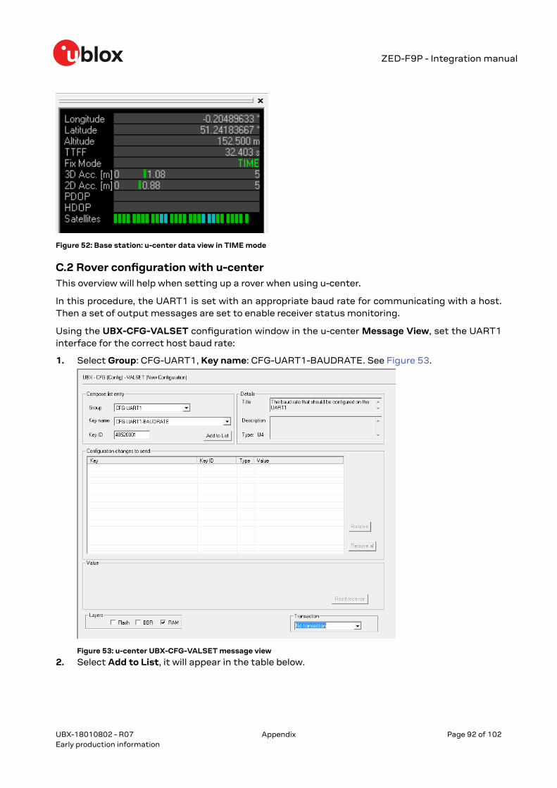
ZED-F9P - Integration manual
Figure 52: Base station: u-center data view in TIME mode
C.2 Rover configuration with u-centerThis overview will help when setting up a rover when using u-center.
In this procedure, the UART1 is set with an appropriate baud rate for communicating with a host.Then a set of output messages are set to enable receiver status monitoring.
Using the UBX-CFG-VALSET configuration window in the u-center Message View, set the UART1interface for the correct host baud rate:
1. Select Group: CFG-UART1, Key name: CFG-UART1-BAUDRATE. See Figure 53.
Figure 53: u-center UBX-CFG-VALSET message view
2. Select Add to List, it will appear in the table below.
UBX-18010802 - R07
Appendix Page 92 of 102Early production information
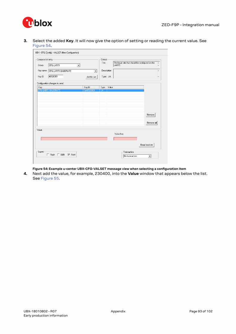
ZED-F9P - Integration manual
3. Select the added Key. It will now give the option of setting or reading the current value. SeeFigure 54.
Figure 54: Example u-center UBX-CFG-VALSET message view when selecting a configuration item
4. Next add the value, for example, 230400, into the Value window that appears below the list.See Figure 55.
UBX-18010802 - R07
Appendix Page 93 of 102Early production information

ZED-F9P - Integration manual
5. Then set the configuration by clicking the Send button at the bottom of the message treeview. Remember to set the u-center baud rate to match the value set in the receiver.
Figure 55: Rover: u-center UBX-CFG-VALSET message view for setting the CFG-UART1-BAUDRATE configurationitem that controls the baudrate of UART1
Next, some UBX example messages are configured to enable viewing the rover status.
1. Select Group CFG-MSGOUT, Key name: CFG-MSGOUT-UBX and select the UART1 requiredmessages.
2. Add each message to the list, setting the value of each to 1.
UBX-18010802 - R07
Appendix Page 94 of 102Early production information

ZED-F9P - Integration manual
3. Click Send. See Figure 56.
Figure 56: Rover: u-center UBX-CFG-VALSET message view for setting the CFG-MSGOUT-* configuration items forenabling the output of some recommended UBX messages
To ensure all the required RTCM messages, including most importantly RTCM 1005, are beingreceived regularly, examine the UBX-RXM-RTCM output in u-center. See Figure 57.
UBX-18010802 - R07
Appendix Page 95 of 102Early production information

ZED-F9P - Integration manual
Figure 57: Rover: u-center UBX-RXM-RTCM view
Once the rover has started to receive valid RTCM messages, it will transition through 3D Fix to 3D/DGNSS to Float, and, ultimately, into Fixed mode. This will occur when it is receiving all requiredRTCM messages, including RTCM 1005, under sufficient signal conditions. See Figure 58.
Figure 58: Rover: u-center data view with RTK Fixed
If using a virtual reference service, the rover must output the NMEA GGA message to returnto the NTRIP caster. Without this, the NTRIP caster will not provide correction information.NMEA messages are enabled by default on the UART1, I2C, SPI and USB interface.
D Stacked patch antennaA typical low-cost L1 + L2 antenna is based on a stacked patch antenna design. This consists of twodiscrete ceramic patch elements with an L1 patch above an L2 patch.
UBX-18010802 - R07
Appendix Page 96 of 102Early production information
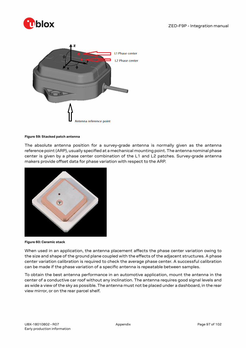
ZED-F9P - Integration manual
Figure 59: Stacked patch antenna
The absolute antenna position for a survey-grade antenna is normally given as the antennareference point (ARP), usually specified at a mechanical mounting point. The antenna nominal phasecenter is given by a phase center combination of the L1 and L2 patches. Survey-grade antennamakers provide offset data for phase variation with respect to the ARP.
Figure 60: Ceramic stack
When used in an application, the antenna placement affects the phase center variation owing tothe size and shape of the ground plane coupled with the effects of the adjacent structures. A phasecenter variation calibration is required to check the average phase center. A successful calibrationcan be made if the phase variation of a specific antenna is repeatable between samples.
To obtain the best antenna performance in an automotive application, mount the antenna in thecenter of a conductive car roof without any inclination. The antenna requires good signal levels andas wide a view of the sky as possible. The antenna must not be placed under a dashboard, in the rearview mirror, or on the rear parcel shelf.
UBX-18010802 - R07
Appendix Page 97 of 102Early production information
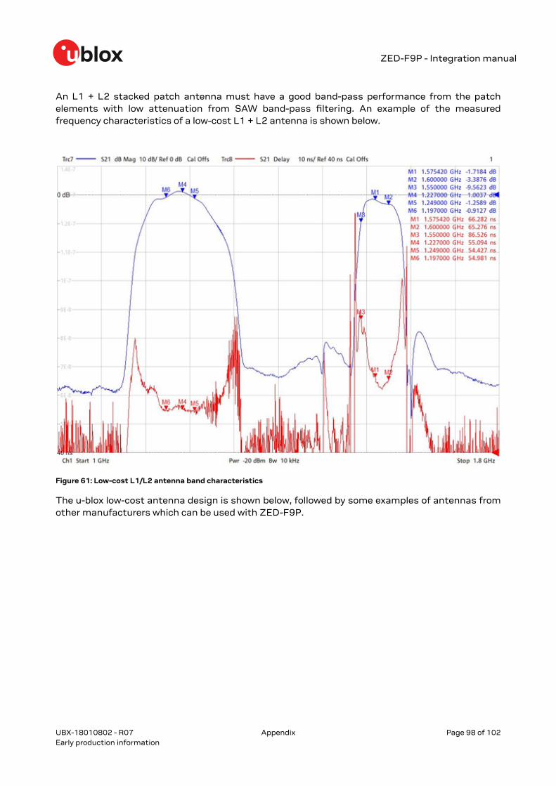
ZED-F9P - Integration manual
An L1 + L2 stacked patch antenna must have a good band-pass performance from the patchelements with low attenuation from SAW band-pass filtering. An example of the measuredfrequency characteristics of a low-cost L1 + L2 antenna is shown below.
Figure 61: Low-cost L1/L2 antenna band characteristics
The u-blox low-cost antenna design is shown below, followed by some examples of antennas fromother manufacturers which can be used with ZED-F9P.
UBX-18010802 - R07
Appendix Page 98 of 102Early production information
ZED-F9P - Integration manual
Figure 62: u-blox low-cost L1/L2 RTK antenna
There are antenna types that can be used without a substantial ground plane, such as a helicalantenna type. This is a useful solution where space is limited, for example, for drone or small formfactor applications.
UBX-18010802 - R07
Appendix Page 99 of 102Early production information

ZED-F9P - Integration manual
Related documents[1] ZED-F9P Data sheet, doc. no. UBX-17051259[2] ZED-F9P Interface description, doc. no. UBX-18010854[3] u-blox Package Information Guide, doc. no. UBX-14001652[4] ZED-F9P Moving Base application note, doc. no. UBX-19009093
For regular updates to u-blox documentation and to receive product change notificationsplease register on our homepage (http://www.u-blox.com).
UBX-18010802 - R07
Related documents Page 100 of 102Early production information

ZED-F9P - Integration manual
Revision historyRevision Date Name Status / comments
R01 22-May-2018 ghun Objective specification
R02 03-Oct-2018 ghun Advance information
R03 20-Dec-2018 byou HPG 1.10 advance information
R04 1-Mar-2019 byou HPG 1.11 early production information.Added a design-in restriction for ANT_DETECT pin in section Design.
R05 22-Aug-2019 ghun HPG 1.12 Early Production Information.
R06 15-Jan-2020 dama Tape feed and dimension pictures updated. PCN UBX-19057484 added andmodule type number updated.
R07 25-Feb-2020 jhak Updated minimum and maximum gains in Antenna specifications table.
UBX-18010802 - R07
Revision history Page 101 of 102Early production information
ZED-F9P - Integration manual
ContactFor complete contact information visit us at www.u-blox.com.
u-blox Offices
North, Central and South America Headquarters Asia, Australia, Pacific
Europe, Middle East, Africa
u-blox America, Inc. u-blox AG u-blox Singapore Pte. Ltd.Phone: +1 703 483 3180 Phone: +41 44 722 74 44 Phone: +65 6734 3811E-mail: [email protected] E-mail: [email protected] E-mail: [email protected] Support: [email protected] Support: [email protected]
Regional Office West Coast Regional Office AustraliaPhone: +1 408 573 3640 Phone: +61 2 8448 2016E-mail: [email protected] E-mail: [email protected] Support: [email protected]
Technical Support Regional Office China (Beijing)Phone: +1 703 483 3185 Phone: +86 10 68 133 545E-mail: [email protected] E-mail: [email protected] Support: [email protected]
Regional Office China (Chongqing) Phone: +86 23 6815 1588 E-mail: [email protected] Support: [email protected]
Regional Office China (Shanghai) Phone: +86 21 6090 4832 E-mail: [email protected] Support: [email protected]
Regional Office China (Shenzhen) Phone: +86 755 8627 1083 E-mail: [email protected] Support: [email protected]
Regional Office India Phone: +91 80 4050 9200 E-mail: [email protected] Support: [email protected]
Regional Office Japan (Osaka) Phone: +81 6 6941 3660 E-mail: [email protected] Support: [email protected]
Regional Office Japan (Tokyo) Phone: +81 3 5775 3850 E-mail: [email protected] Support: [email protected]
Regional Office Korea Phone: +82 2 542 0861 E-mail: [email protected] Support: [email protected]
Regional Office Taiwan Phone: +886 2 2657 1090 E-mail: [email protected] Support: [email protected]
UBX-18010802 - R07
Page 102 of 102Early production information